KR20160136408A - Method and apparatus for fabricating a composite object - Google Patents
Method and apparatus for fabricating a composite objectDownload PDFInfo
- Publication number
- KR20160136408A KR20160136408AKR1020167029468AKR20167029468AKR20160136408AKR 20160136408 AKR20160136408 AKR 20160136408AKR 1020167029468 AKR1020167029468 AKR 1020167029468AKR 20167029468 AKR20167029468 AKR 20167029468AKR 20160136408 AKR20160136408 AKR 20160136408A
- Authority
- KR
- South Korea
- Prior art keywords
- head
- platform
- moving
- selectively
- portions
- Prior art date
- Legal status (The legal status is an assumption and is not a legal conclusion. Google has not performed a legal analysis and makes no representation as to the accuracy of the status listed.)
- Abandoned
Links
- 239000002131composite materialSubstances0.000titleclaimsabstractdescription66
- 238000000034methodMethods0.000titleclaimsabstractdescription37
- 239000000463materialSubstances0.000claimsabstractdescription136
- 238000004519manufacturing processMethods0.000claimsabstractdescription30
- 239000007788liquidSubstances0.000claimsabstractdescription17
- 238000010030laminatingMethods0.000claimsabstractdescription10
- 230000001112coagulating effectEffects0.000claimsabstractdescription8
- 230000004913activationEffects0.000claimsdescription51
- 238000003475laminationMethods0.000claimsdescription31
- 239000000835fiberSubstances0.000claimsdescription20
- 238000004891communicationMethods0.000claimsdescription12
- 230000003213activating effectEffects0.000claimsdescription8
- 230000004044responseEffects0.000claimsdescription4
- 239000007921spraySubstances0.000claimsdescription3
- 239000011324beadSubstances0.000description20
- 230000000704physical effectEffects0.000description8
- 239000000047productSubstances0.000description8
- 230000008569processEffects0.000description7
- 239000011347resinSubstances0.000description5
- 229920005989resinPolymers0.000description5
- 230000004048modificationEffects0.000description4
- 238000012986modificationMethods0.000description4
- 239000000654additiveSubstances0.000description3
- 230000000996additive effectEffects0.000description3
- 239000007789gasSubstances0.000description3
- 229920005830Polyurethane FoamPolymers0.000description2
- 230000008901benefitEffects0.000description2
- 239000000919ceramicSubstances0.000description2
- 238000001723curingMethods0.000description2
- 239000006261foam materialSubstances0.000description2
- 230000006870functionEffects0.000description2
- 238000001459lithographyMethods0.000description2
- 239000002184metalSubstances0.000description2
- 239000011496polyurethane foamSubstances0.000description2
- 238000000110selective laser sinteringMethods0.000description2
- 239000000725suspensionSubstances0.000description2
- 2380000101463D printingMethods0.000description1
- 229920000049Carbon (fiber)Polymers0.000description1
- 239000004606Fillers/ExtendersSubstances0.000description1
- 230000004075alterationEffects0.000description1
- QVGXLLKOCUKJST-UHFFFAOYSA-Natomic oxygenChemical compound[O]QVGXLLKOCUKJST-UHFFFAOYSA-N0.000description1
- 230000004888barrier functionEffects0.000description1
- 239000004917carbon fiberSubstances0.000description1
- 239000013043chemical agentSubstances0.000description1
- 150000001875compoundsChemical class0.000description1
- 239000004020conductorSubstances0.000description1
- 230000008021depositionEffects0.000description1
- 230000001066destructive effectEffects0.000description1
- 238000009826distributionMethods0.000description1
- 239000012777electrically insulating materialSubstances0.000description1
- 230000005611electricityEffects0.000description1
- 238000001125extrusionMethods0.000description1
- 239000000945fillerSubstances0.000description1
- 239000012467final productSubstances0.000description1
- 229910052602gypsumInorganic materials0.000description1
- 239000010440gypsumSubstances0.000description1
- 238000010438heat treatmentMethods0.000description1
- 238000001746injection mouldingMethods0.000description1
- 239000007791liquid phaseSubstances0.000description1
- 239000002923metal particleSubstances0.000description1
- VNWKTOKETHGBQD-UHFFFAOYSA-NmethaneChemical compoundCVNWKTOKETHGBQD-UHFFFAOYSA-N0.000description1
- 239000000203mixtureSubstances0.000description1
- 229910052760oxygenInorganic materials0.000description1
- 239000001301oxygenSubstances0.000description1
- 238000000016photochemical curingMethods0.000description1
- 229920005594polymer fiberPolymers0.000description1
- 230000003014reinforcing effectEffects0.000description1
- 229910001285shape-memory alloyInorganic materials0.000description1
- 239000002195soluble materialSubstances0.000description1
- 230000007480spreadingEffects0.000description1
- 238000003892spreadingMethods0.000description1
Images


Classifications
- B29C67/0066—
- B—PERFORMING OPERATIONS; TRANSPORTING
- B29—WORKING OF PLASTICS; WORKING OF SUBSTANCES IN A PLASTIC STATE IN GENERAL
- B29C—SHAPING OR JOINING OF PLASTICS; SHAPING OF MATERIAL IN A PLASTIC STATE, NOT OTHERWISE PROVIDED FOR; AFTER-TREATMENT OF THE SHAPED PRODUCTS, e.g. REPAIRING
- B29C64/00—Additive manufacturing, i.e. manufacturing of three-dimensional [3D] objects by additive deposition, additive agglomeration or additive layering, e.g. by 3D printing, stereolithography or selective laser sintering
- B29C64/10—Processes of additive manufacturing
- B29C64/106—Processes of additive manufacturing using only liquids or viscous materials, e.g. depositing a continuous bead of viscous material
- B29C64/118—Processes of additive manufacturing using only liquids or viscous materials, e.g. depositing a continuous bead of viscous material using filamentary material being melted, e.g. fused deposition modelling [FDM]
- B—PERFORMING OPERATIONS; TRANSPORTING
- B29—WORKING OF PLASTICS; WORKING OF SUBSTANCES IN A PLASTIC STATE IN GENERAL
- B29C—SHAPING OR JOINING OF PLASTICS; SHAPING OF MATERIAL IN A PLASTIC STATE, NOT OTHERWISE PROVIDED FOR; AFTER-TREATMENT OF THE SHAPED PRODUCTS, e.g. REPAIRING
- B29C31/00—Handling, e.g. feeding of the material to be shaped, storage of plastics material before moulding; Automation, i.e. automated handling lines in plastics processing plants, e.g. using manipulators or robots
- B29C31/04—Feeding of the material to be moulded, e.g. into a mould cavity
- B29C31/042—Feeding of the material to be moulded, e.g. into a mould cavity using dispensing heads, e.g. extruders, placed over or apart from the moulds
- B29C31/044—Feeding of the material to be moulded, e.g. into a mould cavity using dispensing heads, e.g. extruders, placed over or apart from the moulds with moving heads for distributing liquid or viscous material into the moulds
- B29C31/045—Feeding of the material to be moulded, e.g. into a mould cavity using dispensing heads, e.g. extruders, placed over or apart from the moulds with moving heads for distributing liquid or viscous material into the moulds moving along predetermined circuits or distributing the material according to predetermined patterns
- B—PERFORMING OPERATIONS; TRANSPORTING
- B29—WORKING OF PLASTICS; WORKING OF SUBSTANCES IN A PLASTIC STATE IN GENERAL
- B29C—SHAPING OR JOINING OF PLASTICS; SHAPING OF MATERIAL IN A PLASTIC STATE, NOT OTHERWISE PROVIDED FOR; AFTER-TREATMENT OF THE SHAPED PRODUCTS, e.g. REPAIRING
- B29C64/00—Additive manufacturing, i.e. manufacturing of three-dimensional [3D] objects by additive deposition, additive agglomeration or additive layering, e.g. by 3D printing, stereolithography or selective laser sintering
- B29C64/10—Processes of additive manufacturing
- B29C64/106—Processes of additive manufacturing using only liquids or viscous materials, e.g. depositing a continuous bead of viscous material
- B29C64/124—Processes of additive manufacturing using only liquids or viscous materials, e.g. depositing a continuous bead of viscous material using layers of liquid which are selectively solidified
- B29C64/129—Processes of additive manufacturing using only liquids or viscous materials, e.g. depositing a continuous bead of viscous material using layers of liquid which are selectively solidified characterised by the energy source therefor, e.g. by global irradiation combined with a mask
- B29C64/135—Processes of additive manufacturing using only liquids or viscous materials, e.g. depositing a continuous bead of viscous material using layers of liquid which are selectively solidified characterised by the energy source therefor, e.g. by global irradiation combined with a mask the energy source being concentrated, e.g. scanning lasers or focused light sources
- B—PERFORMING OPERATIONS; TRANSPORTING
- B29—WORKING OF PLASTICS; WORKING OF SUBSTANCES IN A PLASTIC STATE IN GENERAL
- B29C—SHAPING OR JOINING OF PLASTICS; SHAPING OF MATERIAL IN A PLASTIC STATE, NOT OTHERWISE PROVIDED FOR; AFTER-TREATMENT OF THE SHAPED PRODUCTS, e.g. REPAIRING
- B29C64/00—Additive manufacturing, i.e. manufacturing of three-dimensional [3D] objects by additive deposition, additive agglomeration or additive layering, e.g. by 3D printing, stereolithography or selective laser sintering
- B29C64/10—Processes of additive manufacturing
- B29C64/165—Processes of additive manufacturing using a combination of solid and fluid materials, e.g. a powder selectively bound by a liquid binder, catalyst, inhibitor or energy absorber
- B—PERFORMING OPERATIONS; TRANSPORTING
- B29—WORKING OF PLASTICS; WORKING OF SUBSTANCES IN A PLASTIC STATE IN GENERAL
- B29C—SHAPING OR JOINING OF PLASTICS; SHAPING OF MATERIAL IN A PLASTIC STATE, NOT OTHERWISE PROVIDED FOR; AFTER-TREATMENT OF THE SHAPED PRODUCTS, e.g. REPAIRING
- B29C64/00—Additive manufacturing, i.e. manufacturing of three-dimensional [3D] objects by additive deposition, additive agglomeration or additive layering, e.g. by 3D printing, stereolithography or selective laser sintering
- B29C64/20—Apparatus for additive manufacturing; Details thereof or accessories therefor
- B29C64/205—Means for applying layers
- B29C64/209—Heads; Nozzles
- B—PERFORMING OPERATIONS; TRANSPORTING
- B29—WORKING OF PLASTICS; WORKING OF SUBSTANCES IN A PLASTIC STATE IN GENERAL
- B29C—SHAPING OR JOINING OF PLASTICS; SHAPING OF MATERIAL IN A PLASTIC STATE, NOT OTHERWISE PROVIDED FOR; AFTER-TREATMENT OF THE SHAPED PRODUCTS, e.g. REPAIRING
- B29C64/00—Additive manufacturing, i.e. manufacturing of three-dimensional [3D] objects by additive deposition, additive agglomeration or additive layering, e.g. by 3D printing, stereolithography or selective laser sintering
- B29C64/20—Apparatus for additive manufacturing; Details thereof or accessories therefor
- B29C64/227—Driving means
- B—PERFORMING OPERATIONS; TRANSPORTING
- B29—WORKING OF PLASTICS; WORKING OF SUBSTANCES IN A PLASTIC STATE IN GENERAL
- B29C—SHAPING OR JOINING OF PLASTICS; SHAPING OF MATERIAL IN A PLASTIC STATE, NOT OTHERWISE PROVIDED FOR; AFTER-TREATMENT OF THE SHAPED PRODUCTS, e.g. REPAIRING
- B29C64/00—Additive manufacturing, i.e. manufacturing of three-dimensional [3D] objects by additive deposition, additive agglomeration or additive layering, e.g. by 3D printing, stereolithography or selective laser sintering
- B29C64/20—Apparatus for additive manufacturing; Details thereof or accessories therefor
- B29C64/245—Platforms or substrates
- B—PERFORMING OPERATIONS; TRANSPORTING
- B29—WORKING OF PLASTICS; WORKING OF SUBSTANCES IN A PLASTIC STATE IN GENERAL
- B29C—SHAPING OR JOINING OF PLASTICS; SHAPING OF MATERIAL IN A PLASTIC STATE, NOT OTHERWISE PROVIDED FOR; AFTER-TREATMENT OF THE SHAPED PRODUCTS, e.g. REPAIRING
- B29C64/00—Additive manufacturing, i.e. manufacturing of three-dimensional [3D] objects by additive deposition, additive agglomeration or additive layering, e.g. by 3D printing, stereolithography or selective laser sintering
- B29C64/20—Apparatus for additive manufacturing; Details thereof or accessories therefor
- B29C64/264—Arrangements for irradiation
- B29C64/268—Arrangements for irradiation using laser beams; using electron beams [EB]
- B29C64/273—Arrangements for irradiation using laser beams; using electron beams [EB] pulsed; frequency modulated
- B—PERFORMING OPERATIONS; TRANSPORTING
- B29—WORKING OF PLASTICS; WORKING OF SUBSTANCES IN A PLASTIC STATE IN GENERAL
- B29C—SHAPING OR JOINING OF PLASTICS; SHAPING OF MATERIAL IN A PLASTIC STATE, NOT OTHERWISE PROVIDED FOR; AFTER-TREATMENT OF THE SHAPED PRODUCTS, e.g. REPAIRING
- B29C64/00—Additive manufacturing, i.e. manufacturing of three-dimensional [3D] objects by additive deposition, additive agglomeration or additive layering, e.g. by 3D printing, stereolithography or selective laser sintering
- B29C64/20—Apparatus for additive manufacturing; Details thereof or accessories therefor
- B29C64/264—Arrangements for irradiation
- B29C64/277—Arrangements for irradiation using multiple radiation means, e.g. micromirrors or multiple light-emitting diodes [LED]
- B29C64/282—Arrangements for irradiation using multiple radiation means, e.g. micromirrors or multiple light-emitting diodes [LED] of the same type, e.g. using different energy levels
- B—PERFORMING OPERATIONS; TRANSPORTING
- B29—WORKING OF PLASTICS; WORKING OF SUBSTANCES IN A PLASTIC STATE IN GENERAL
- B29C—SHAPING OR JOINING OF PLASTICS; SHAPING OF MATERIAL IN A PLASTIC STATE, NOT OTHERWISE PROVIDED FOR; AFTER-TREATMENT OF THE SHAPED PRODUCTS, e.g. REPAIRING
- B29C64/00—Additive manufacturing, i.e. manufacturing of three-dimensional [3D] objects by additive deposition, additive agglomeration or additive layering, e.g. by 3D printing, stereolithography or selective laser sintering
- B29C64/20—Apparatus for additive manufacturing; Details thereof or accessories therefor
- B29C64/264—Arrangements for irradiation
- B29C64/286—Optical filters, e.g. masks
- B—PERFORMING OPERATIONS; TRANSPORTING
- B29—WORKING OF PLASTICS; WORKING OF SUBSTANCES IN A PLASTIC STATE IN GENERAL
- B29C—SHAPING OR JOINING OF PLASTICS; SHAPING OF MATERIAL IN A PLASTIC STATE, NOT OTHERWISE PROVIDED FOR; AFTER-TREATMENT OF THE SHAPED PRODUCTS, e.g. REPAIRING
- B29C64/00—Additive manufacturing, i.e. manufacturing of three-dimensional [3D] objects by additive deposition, additive agglomeration or additive layering, e.g. by 3D printing, stereolithography or selective laser sintering
- B29C64/20—Apparatus for additive manufacturing; Details thereof or accessories therefor
- B29C64/264—Arrangements for irradiation
- B29C64/291—Arrangements for irradiation for operating globally, e.g. together with selectively applied activators or inhibitors
- B—PERFORMING OPERATIONS; TRANSPORTING
- B29—WORKING OF PLASTICS; WORKING OF SUBSTANCES IN A PLASTIC STATE IN GENERAL
- B29C—SHAPING OR JOINING OF PLASTICS; SHAPING OF MATERIAL IN A PLASTIC STATE, NOT OTHERWISE PROVIDED FOR; AFTER-TREATMENT OF THE SHAPED PRODUCTS, e.g. REPAIRING
- B29C64/00—Additive manufacturing, i.e. manufacturing of three-dimensional [3D] objects by additive deposition, additive agglomeration or additive layering, e.g. by 3D printing, stereolithography or selective laser sintering
- B29C64/30—Auxiliary operations or equipment
- B29C64/386—Data acquisition or data processing for additive manufacturing
- B29C64/393—Data acquisition or data processing for additive manufacturing for controlling or regulating additive manufacturing processes
- B—PERFORMING OPERATIONS; TRANSPORTING
- B29—WORKING OF PLASTICS; WORKING OF SUBSTANCES IN A PLASTIC STATE IN GENERAL
- B29C—SHAPING OR JOINING OF PLASTICS; SHAPING OF MATERIAL IN A PLASTIC STATE, NOT OTHERWISE PROVIDED FOR; AFTER-TREATMENT OF THE SHAPED PRODUCTS, e.g. REPAIRING
- B29C64/00—Additive manufacturing, i.e. manufacturing of three-dimensional [3D] objects by additive deposition, additive agglomeration or additive layering, e.g. by 3D printing, stereolithography or selective laser sintering
- B29C64/40—Structures for supporting 3D objects during manufacture and intended to be sacrificed after completion thereof
- B29C67/0085—
- B—PERFORMING OPERATIONS; TRANSPORTING
- B29—WORKING OF PLASTICS; WORKING OF SUBSTANCES IN A PLASTIC STATE IN GENERAL
- B29C—SHAPING OR JOINING OF PLASTICS; SHAPING OF MATERIAL IN A PLASTIC STATE, NOT OTHERWISE PROVIDED FOR; AFTER-TREATMENT OF THE SHAPED PRODUCTS, e.g. REPAIRING
- B29C70/00—Shaping composites, i.e. plastics material comprising reinforcements, fillers or preformed parts, e.g. inserts
- B29C70/04—Shaping composites, i.e. plastics material comprising reinforcements, fillers or preformed parts, e.g. inserts comprising reinforcements only, e.g. self-reinforcing plastics
- B29C70/28—Shaping operations therefor
- B29C70/30—Shaping by lay-up, i.e. applying fibres, tape or broadsheet on a mould, former or core; Shaping by spray-up, i.e. spraying of fibres on a mould, former or core
- B29C70/38—Automated lay-up, e.g. using robots, laying filaments according to predetermined patterns
- B29C70/382—Automated fiber placement [AFP]
- B29C70/384—Fiber placement heads, e.g. component parts, details or accessories
- B—PERFORMING OPERATIONS; TRANSPORTING
- B29—WORKING OF PLASTICS; WORKING OF SUBSTANCES IN A PLASTIC STATE IN GENERAL
- B29C—SHAPING OR JOINING OF PLASTICS; SHAPING OF MATERIAL IN A PLASTIC STATE, NOT OTHERWISE PROVIDED FOR; AFTER-TREATMENT OF THE SHAPED PRODUCTS, e.g. REPAIRING
- B29C70/00—Shaping composites, i.e. plastics material comprising reinforcements, fillers or preformed parts, e.g. inserts
- B29C70/04—Shaping composites, i.e. plastics material comprising reinforcements, fillers or preformed parts, e.g. inserts comprising reinforcements only, e.g. self-reinforcing plastics
- B29C70/28—Shaping operations therefor
- B29C70/54—Component parts, details or accessories; Auxiliary operations, e.g. feeding or storage of prepregs or SMC after impregnation or during ageing
- B29C70/541—Positioning reinforcements in a mould, e.g. using clamping means for the reinforcement
- B—PERFORMING OPERATIONS; TRANSPORTING
- B29—WORKING OF PLASTICS; WORKING OF SUBSTANCES IN A PLASTIC STATE IN GENERAL
- B29C—SHAPING OR JOINING OF PLASTICS; SHAPING OF MATERIAL IN A PLASTIC STATE, NOT OTHERWISE PROVIDED FOR; AFTER-TREATMENT OF THE SHAPED PRODUCTS, e.g. REPAIRING
- B29C70/00—Shaping composites, i.e. plastics material comprising reinforcements, fillers or preformed parts, e.g. inserts
- B29C70/68—Shaping composites, i.e. plastics material comprising reinforcements, fillers or preformed parts, e.g. inserts by incorporating or moulding on preformed parts, e.g. inserts or layers, e.g. foam blocks
- B29C70/681—Component parts, details or accessories; Auxiliary operations
- B—PERFORMING OPERATIONS; TRANSPORTING
- B33—ADDITIVE MANUFACTURING TECHNOLOGY
- B33Y—ADDITIVE MANUFACTURING, i.e. MANUFACTURING OF THREE-DIMENSIONAL [3-D] OBJECTS BY ADDITIVE DEPOSITION, ADDITIVE AGGLOMERATION OR ADDITIVE LAYERING, e.g. BY 3-D PRINTING, STEREOLITHOGRAPHY OR SELECTIVE LASER SINTERING
- B33Y30/00—Apparatus for additive manufacturing; Details thereof or accessories therefor
- B—PERFORMING OPERATIONS; TRANSPORTING
- B33—ADDITIVE MANUFACTURING TECHNOLOGY
- B33Y—ADDITIVE MANUFACTURING, i.e. MANUFACTURING OF THREE-DIMENSIONAL [3-D] OBJECTS BY ADDITIVE DEPOSITION, ADDITIVE AGGLOMERATION OR ADDITIVE LAYERING, e.g. BY 3-D PRINTING, STEREOLITHOGRAPHY OR SELECTIVE LASER SINTERING
- B33Y50/00—Data acquisition or data processing for additive manufacturing
- B33Y50/02—Data acquisition or data processing for additive manufacturing for controlling or regulating additive manufacturing processes
- B—PERFORMING OPERATIONS; TRANSPORTING
- B29—WORKING OF PLASTICS; WORKING OF SUBSTANCES IN A PLASTIC STATE IN GENERAL
- B29C—SHAPING OR JOINING OF PLASTICS; SHAPING OF MATERIAL IN A PLASTIC STATE, NOT OTHERWISE PROVIDED FOR; AFTER-TREATMENT OF THE SHAPED PRODUCTS, e.g. REPAIRING
- B29C64/00—Additive manufacturing, i.e. manufacturing of three-dimensional [3D] objects by additive deposition, additive agglomeration or additive layering, e.g. by 3D printing, stereolithography or selective laser sintering
- B29C64/20—Apparatus for additive manufacturing; Details thereof or accessories therefor
- B29C64/264—Arrangements for irradiation
- B29C64/268—Arrangements for irradiation using laser beams; using electron beams [EB]
- B—PERFORMING OPERATIONS; TRANSPORTING
- B29—WORKING OF PLASTICS; WORKING OF SUBSTANCES IN A PLASTIC STATE IN GENERAL
- B29K—INDEXING SCHEME ASSOCIATED WITH SUBCLASSES B29B, B29C OR B29D, RELATING TO MOULDING MATERIALS OR TO MATERIALS FOR MOULDS, REINFORCEMENTS, FILLERS OR PREFORMED PARTS, e.g. INSERTS
- B29K2105/00—Condition, form or state of moulded material or of the material to be shaped
- B29K2105/0058—Liquid or visquous
- B—PERFORMING OPERATIONS; TRANSPORTING
- B29—WORKING OF PLASTICS; WORKING OF SUBSTANCES IN A PLASTIC STATE IN GENERAL
- B29K—INDEXING SCHEME ASSOCIATED WITH SUBCLASSES B29B, B29C OR B29D, RELATING TO MOULDING MATERIALS OR TO MATERIALS FOR MOULDS, REINFORCEMENTS, FILLERS OR PREFORMED PARTS, e.g. INSERTS
- B29K2105/00—Condition, form or state of moulded material or of the material to be shaped
- B29K2105/06—Condition, form or state of moulded material or of the material to be shaped containing reinforcements, fillers or inserts
- B29K2105/12—Condition, form or state of moulded material or of the material to be shaped containing reinforcements, fillers or inserts of short lengths, e.g. chopped filaments, staple fibres or bristles
- B—PERFORMING OPERATIONS; TRANSPORTING
- B33—ADDITIVE MANUFACTURING TECHNOLOGY
- B33Y—ADDITIVE MANUFACTURING, i.e. MANUFACTURING OF THREE-DIMENSIONAL [3-D] OBJECTS BY ADDITIVE DEPOSITION, ADDITIVE AGGLOMERATION OR ADDITIVE LAYERING, e.g. BY 3-D PRINTING, STEREOLITHOGRAPHY OR SELECTIVE LASER SINTERING
- B33Y10/00—Processes of additive manufacturing
Landscapes
- Engineering & Computer Science (AREA)
- Chemical & Material Sciences (AREA)
- Materials Engineering (AREA)
- Mechanical Engineering (AREA)
- Manufacturing & Machinery (AREA)
- Optics & Photonics (AREA)
- Physics & Mathematics (AREA)
- Health & Medical Sciences (AREA)
- Toxicology (AREA)
- Composite Materials (AREA)
- Robotics (AREA)
- Microelectronics & Electronic Packaging (AREA)
- Plasma & Fusion (AREA)
Abstract
Translated fromKoreanDescription
Translated fromKorean본 발명은 일반적으로 둘 이상의 재료를 포함하는 복합형 물체를 제조하는 것에 관한 것으로, 특히 컴퓨터-제어 장치로 실질적으로 액체이며 경화성인 재료를 사용하여 복합형 물체를 제조하는 것에 관한 것이다.Field of the Invention The present invention relates generally to the fabrication of composite objects comprising two or more materials, and more particularly to the production of composite objects using a material that is substantially liquid and curable with a computer-controlled device.
둘 또는 그 이상의 재료들이 조합된 물성에서 발현되는 이점을 얻기 위해, 일반적으로 복합형 물체(composite object)는 둘 또는 그 이상의 재료들로 형성된다. 예를 들면, 자전거 프레임 같은 물체를 복합 재료인 탄소 파이버로 제작하는 것이 통상적인데, 이는 복합재 사이클 프레임이 무게 대비 강성 비가 유리하기 때문이다.In order to obtain the advantage that two or more materials are expressed in combined physical properties, a composite object is generally formed of two or more materials. For example, it is common to fabricate an object, such as a bicycle frame, with a carbon fiber, a composite material, because the composite cycle frame is advantageous in terms of weight to stiffness ratio.
통상적으로 3D 프린팅으로 알려져 있는 재료부가형 제조 방법은 물체를 제조하는 데에 사용되는 제조 기술 중 하나이다. 재료부가형 제조 공정은 일반적으로, 컴퓨터 소프트웨어로 물체의 디지털 3D 모델을 준비하는 단계, 3D 모델로부터 물체 형상의 평행하며, 평면형인 일련의 단면을 획정하는 컴퓨터 지령을 도출하는 단계, 3D 프린터에 그 컴퓨터 지령을 제공하는 단계를 포함하며, 컴퓨터 지령은 3D 프린터를 안내하여 제조하고자 하는 물체의 모든 층들이 제조될 때까지 단면에 대응하는 재료의 연속된 층을 서로의 위에 연속적으로 제조하게 된다.A material additive manufacturing method, commonly known as 3D printing, is one of the manufacturing techniques used to manufacture an object. A material additive type manufacturing process generally comprises preparing a digital 3D model of an object with computer software, deriving a computer command defining a series of parallel, planar object shapes of the object shape from the 3D model, The computer instructions guiding the 3D printer to continuously produce successive layers of material corresponding to the cross section on top of each other until all layers of the object to be fabricated are fabricated.
다양한 많은 유형의 재료부가형 제조 공정이 존재하고 있지만, 그 중에서도 스테레오리소그래피(SLA), 선택적 레이저 소결법(SLS) 및 용융 필라멘트 제조법(FFF)이 가장 널리 사용되고 있다. 스테레오리소그래피는 광경화성 액상 수지가 담긴 통의 상면 위에서 광원(일반적으로 자외선 레이저 또는 램프)으로 물체의 단면을 추종하여, 광원이 쪼여지는 상면에서 액상의 광경화성 수지가 일정 깊이로 경화되게 하는 공정을 포함한다. 경화된 광경화성 수지는 물체의 일 층을 형성하며, 통 내에 배치되어 있는 플랫폼 위에 지지되어 있다. 한 층이 제조된 후, 플랫폼이 그 층 두께만큼 통 안쪽으로 하강하고, 제2 단면이 추적되어 제1 층에 접착되는 제2 층을 형성하게 된다. 물체가 제조될 때까지, 연속된 층이 제조되고 플랫폼이 연속적으로 통 안쪽으로 하강하는 이 공정이 반복된다.Many different types of material additive manufacturing processes exist, among which the most widely used are SLR, selective laser sintering (SLS) and melt filament manufacturing (FFF). Stereolithography is a process in which the cross-section of an object is followed by a light source (usually an ultraviolet laser or a lamp) on the top surface of a barrel containing the photo-curable liquid resin to cure the liquid photo-curing resin from the top surface . The cured photocurable resin forms a layer of the object and is supported on a platform disposed in the cylinder. After one layer is fabricated, the platform is lowered into the pod by its layer thickness, and the second cross-section is traced to form a second layer bonded to the first layer. This process is repeated until a continuous layer is produced and the platform is continuously lowered into the barrel until the object is manufactured.
스테레오리소그래피는 사출 성형 같은 종래의 제조 기법에 비해 많은 이점을 제공한다. 그러나 스테레오리소그래피는 많은 단점도 안고 있다. 예를 들어, 스테레오리소그래피를 사용하여, 강도가 크거나 또는 밀도가 작은 것과 같이 특정한 물리적 물성을 구비하는 복합재로 물체를 제조하는 것이 유용할 경우가 상당히 많다. 이를 해결하기 위한 과거의 시도들은, 세라믹 또는 금속 입자 같은 필러들을 액상의 광경화성 수지에 부가하여 경화성 현탁액(suspension)을 형성하고, 수지가 경화되어 복합형 물체를 제조하는 것을 포함한다. 그러나 경화성 현탁액은 상당히 균질해서, 제조되는 복합형 물체가 물체 전반에 걸쳐 재료 특성을 일관되게 구비하기 때문에, 복합형 물체의 특정 부분들이 특정의 소망하는 물성을 구비하도록 제조할 수가 없다.Stereolithography offers many advantages over conventional manufacturing techniques such as injection molding. However, stereo lithography has many drawbacks. For example, using stereo lithography, it is often quite useful to fabricate an article with a composite material having certain physical properties, such as high strength or low density. Previous attempts to overcome this have included the addition of fillers such as ceramic or metal particles to a liquid photo-curable resin to form a curable suspension and curing the resin to produce a composite article. However, curable suspensions are fairly homogeneous, so that certain parts of a composite body can not be made to have certain desired properties, as the composite body being produced consistently has material properties throughout the body.
이에 따라, 본 발명은 복합형 물체의 서로 다른 부분들이 서로 다른 물성을 구비하도록 하기 위해, 둘 또는 그 이상의 재료로 복합형 물체를 제조할 수 있는, 액체의 경화성 재료를 선택적으로 응고시키는 장치 또는 방법을 제공하는 것을 일 목적으로 한다.Accordingly, the present invention is directed to an apparatus or method for selectively coagulating a liquid curable material, which can produce a composite body of two or more materials so that different portions of the composite body have different physical properties The present invention has been made in view of the above problems.
본 발명의 일 측면에 의하면, 실질적으로 액체이며 경화성인 제1 재료를 저장하는 저장소, 제1 재료를 응고시키는 활성화 헤드 및 제2 재료 공급부와 연통하는 적층 헤드를 포함하여 구성되고, 상기 활성화 헤드 및 적층 헤드는 상기 저장소에 대해 상대 이동 가능한 컴퓨터-제어 장치를 사용하여 복합형 물체를 제조하는 방법으로, 이 방법은, 상기 장치에 의해 복합형 물체 형상과 관련된 컴퓨터 지령을 수신하는 단계; 복합형 물체 형상에 대응되는 특정 지점에 제2 재료 부분들을 적층하기 위해 적층 헤드를 이동시키고 선택적으로 작동시키는 단계; 복합형 물체 형상에 대응되는 특정 지점에 제1 재료 부분들을 응고시키기 위해 활성화 헤드를 이동시키고 선택적으로 작동시키는 단계;를 포함하되, 제1 재료의 경화된 부분들과 제2 재료의 적층된 부분들이 복합형 물체를 형성하는 것을 특징으로 하는 복합형 물체 제조 방법이 제공된다.According to one aspect of the present invention there is provided a lithographic apparatus comprising a reservoir for storing a first material that is substantially liquid and curable, an activation head for coagulating the first material, and a lamination head in communication with the second material supply, A method of manufacturing a hybrid object using a computer-controlled device that is movable relative to the reservoir, the method comprising: receiving a computer command associated with the hybrid object shape by the apparatus; Moving and selectively operating the stacking head to stack the second material portions at a particular point corresponding to the composite object shape; Moving and selectively actuating the activation head to solidify the first material portions at a particular point corresponding to the composite object shape, wherein the cured portions of the first material and the laminated portions of the second material Thereby forming a composite type object.
본 발명의 다른 측면에 의하면, 복합형 물체를 제조하기 위한 컴퓨터-제어 장치로, 이 장치는, 상부 면을 형성하는 실질적으로 액체이며 경화성인 제1 재료를 저장하는 저장소; 상기 저장소에 대해 상대 이동할 수 있으며, 제1 재료를 응고시키기 위한 활성화 헤드; 상기 저장소에 대해 상대 이동할 수 있으며, 제2 재료 공급부와 연통하는 적층 헤드; 및 복합형 물체의 형상과 관련된 컴퓨터 지령에 응답하여 활성화 헤드 및 적층 헤드를 이동 및 작동시키도록 구성된 컨트롤러;를 포함하고, 상기 컨트롤러는 복합형 물체 형상에 대응되는 특정 지점에 제1 재료 부분들을 응고시키기 위해 활성화 헤드를 이동 및 선택적으로 작동시키고, 그리고 상기 컨트롤러는 복합형 물체 형상에 대응되는 특정 지점에 제2 재료를 적층시키기 위해 적층 헤드를 이동 및 선택적으로 작동시키는 것을 특징으로 하는 복합형 물체를 제조하기 위한 컴퓨터-제어 장치가 제공된다.According to another aspect of the present invention there is provided a computer-controlled apparatus for manufacturing a hybrid object, comprising: a reservoir for storing a substantially liquid, curable first material forming an upper surface; An activation head movable relative to the reservoir and for coagulating the first material; A stacking head movable relative to the reservoir and in communication with the second material supply; And a controller configured to move and actuate the activation head and the lamination head in response to a computer command related to the shape of the composite object, wherein the controller is configured to coagulate the first material portions at a particular point corresponding to the composite object shape And the controller moves and selectively actuates the lamination head to laminate the second material at a particular point corresponding to the composite object shape. ≪ RTI ID = 0.0 > A computer-controlled apparatus for manufacturing is provided.
본 명세서에는 다른 측면들도 기재되어 있다.Other aspects are also described herein.
첨부된 도면들을 참고로 하여 본 발명의 바람직한 실시형태들을 기재한다. 다만 이들 실시형태들은 예시적인 목적을 위한 것이다.
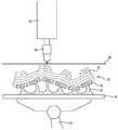
도 1은 복합형 물체를 제조하는 장치의 단면도이다.
도 2는 다른 복합형 물체를 제조하는 도 1에 도시되어 있는 장치의 단면도이다.
도 3은 도 2에 도시되어 있는 물체를 제조하는 도 1 및 도 2에 도시되어 있는 장치를 변형한 장치의 단면도이다.
도 4a 및 도 4b는 다른 물체를 제조하는 도 1 및 도 2에 도시되어 있는 장치의 다른 변형 장치의 단면도이다.
도 5는 도 1 내지 도 4b 중 어느 하나에 도시되어 있는 장치에 의해 제조된 복합형 제품의 단면도이다.
도 6은 또 다른 복합형 제품을 제조하는 도 3에 도시된 장치의 단면도이다.
도 7은 또 다른 복합형 제품을 제조하는 다른 장치의 단면도이다.
도 8은 또 다른 복합형 제품을 제조하는 또 다른 장치의 단면도이다.
도 9는 또 다른 복합형 제품을 제조하는 또 다른 장치의 단면도이다.
도 10a 및 도 10b는 또 다른 제품을 제조하는 또 다른 장치를 나타내는 도면이다.
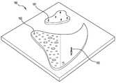
도 11은 고정판의 사시도이다.
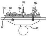
도 12a 내지 도 12e는 도 11에 도시되어 있는 고정판 위에서 또 다른 물체를 제조하는 다양한 단계에 대한 단면도이다.Preferred embodiments of the present invention will be described with reference to the accompanying drawings. However, these embodiments are for illustrative purposes only.
1 is a cross-sectional view of an apparatus for producing a composite object.
Fig. 2 is a cross-sectional view of the apparatus shown in Fig. 1 for producing another composite object.
Fig. 3 is a cross-sectional view of an apparatus for modifying the apparatus shown in Figs. 1 and 2 for producing the object shown in Fig.
Figs. 4A and 4B are cross-sectional views of another modification of the apparatus shown in Figs. 1 and 2 for producing different objects.
5 is a cross-sectional view of a composite article made by the apparatus shown in any of Figs. 1 to 4B.
Figure 6 is a cross-sectional view of the device shown in Figure 3 to produce another hybrid product.
Figure 7 is a cross-sectional view of another apparatus for making another hybrid product.
8 is a cross-sectional view of another apparatus for producing another hybrid product.
Figure 9 is a cross-sectional view of another apparatus for producing another hybrid product.
10A and 10B are views showing another apparatus for manufacturing another product.
11 is a perspective view of the fixing plate.
Figs. 12A to 12E are cross-sectional views for various steps of manufacturing another object on the fixing plate shown in Fig.
본 개시는, 실질적으로 액상의 경화성 제1 재료를 선택적으로 응고시키는 단계와, 특정 지점에 제2 재료를 선택적으로 적층시키는 단계를 포함하여, 제1 재료와 제2 재료가 복합형 물체를 형성하는, 복합형 물체를 제조하는 장치 및 방법에 관한 것이다.The present disclosure relates to a method of forming a composite material, comprising selectively coagulating a substantially liquid curable first material and selectively laminating a second material at a particular point, wherein the first material and the second material form a composite body , And an apparatus and a method for manufacturing a hybrid object.
도 1은 쉘(53)과 일체로 형성되어 있는 코어(52)를 포함하는 복합형 물체(51)를 제조하는 컴퓨터-제어 장치(50)를 도시하고 있다. 이 컴퓨터-제어 장치(50)는 저장소(56) 위에 배치되어 있는 로봇 암(55)에 연결되어 있는 활성화 헤드(activation head)(54)를 구비한다. 상기 저장소(56)는 실질적으로 액상의 경화성 제1 재료(57)로 채워져 있으며, 제1 재료는 상부 면(58)을 획정하고 있다. 활성화 헤드(54)는, 경화성 제1 재료(57)를 경화시키기에 적당한 자외선 레이저나 램프 같은 에너지원(energy source)(도시되어 있지 않음)과 연통하고 있다. 장치가 작동할 때, 활성화 헤드(54)가 에너지원을 노출시키며 에너지원을 저장소(56) 위에 초점을 맞출 수 있다. 적층 헤드(deposition head)(59)가 활성화 헤드(54)에 인접하여 배치되어 있으며, 적층 헤드(59)는 하나 이상의 호스(60)를 통해 제2 재료 공급부와 연통하고 있다. 장치가 작동할 때, 적층 헤드(59)는 일반적으로 압출 혹은 제트 분사 방식으로 제2 재료 부분들을 적층한다. 복합형 물체(51)를 지지하기에 알맞은 하나 이상의 면을 구비하는 플랫폼(61)이 저장소(56) 내에 위치하는 제2 로봇 암(62)에 연결되어 있다. 컴퓨터-제어 장치(50)에 제공되는 코어(52)의 기하학적 구조 또는 쉘(53)의 기하학적 구조와 관련된 컴퓨터 지령에 반응하여, 활성화 헤드(54), 적층 헤드(59) 및 플랫폼(61)이 컨트롤러(도시되어 있지 않음)에 의해 상부 면(58) 및/또는 서로에 대해 상대 이동할 수 있다. 컴퓨터 지령들은 일반적으로 복합형 물체(51)의 디지털 3차원 모델로부터 도출되며, 복합형 물체(51)의 기하학적 구조(형상, geometry)를 획정한다.Fig. 1 shows a computer-controlled
적층 헤드(59)가 제2 재료 부분들을 선택적으로 적층하고, 활성화 헤드(54)가 복합형 물체(51)의 형상에 대응되는 특정 지점에 경화성 제1 재료(57)를 선택적으로 응고시켜서, 복합형 물체(51)가 제조된다. 이는 일반적으로 초기에 상부 면(58) 위로 플랫폼(61)을 위치시키는 단계와, 적층되는 제2 재료의 적어도 일부가 플랫폼(61)과 인접하도록 코어(52) 형상에 대응되는 특정 지점에 제2 재료를 선택적으로 적층하기 위해 적층 헤드(59)를 이동시키고 선택적으로 작동시키는 단계를 포함한다. 그런 다음, 플랫폼(61)이 이동하여 적어도 부분적으로 적층된 제2 재료를 경화성 제1 재료(57) 내로 가라앉게 하며, 활성화 헤드(54)가 이동하여 상부 면(58) 위 근방에서 선택적으로 작동하여, 쉘(53) 형상에 대응되는 특정 지점의 상부 면(58)에서 경화성 제1 재료(57) 부분을 선택적으로 응고시켜, 응고된 부분들의 적어도 일부가 플랫폼(61) 및/또는 적층된 제2 재료와 인접하게 된다. 그런 다음, 일반적으로 상부 면(58)에 대해 적층된 제2 재료와 응고된 제1 재료를 재위치(reposition) 시키기 위해 플랫폼(61)이 다시 이동하는데, 일반적으로 플랫폼(61)이 저장소(56) 내로 하강한다. 이 과정이 반복되어, 제2 재료의 다른 부분들을 선택적으로 적층하고, 제1 재료(57)의 다른 부분들을 응고시켜서 복합형 물체(51)를 제조하게 된다.The
필요에 따라서는, 초기에 상부 면(58)에 가까이 있는 활성화 헤드(54)를 선택적으로 작동시켜 쉘(53)의 형상에 대응되는 경화성 제1 재료(57) 부분들을 응고시켜서 응고된 부분들이 플랫폼(61)에 인접하도록 하고, 그런 다음, 플랫폼(61)을 이동시켜 상부 면(58) 위로 응고된 부분들의 적어도 일부를 위치시킴으로써, 복합형 물체(51)가 제조될 수 있다. 이렇게 함으로써, 응고된 제1 재료 위에 그리고 또한 플랫폼(61) 위에 제2 재료의 부분들을 적층하도록 적층 헤드(59)를 선택적으로 작동시킬 수 있다.Optionally, the
또는, 활성화 헤드(54)가 프로젝터(도시되어 있지 않음)를 포함하고, 상부 면(58) 위로 쉘(53) 형상의 단면을 투사하여 싱글 프로젝션으로 쉘(53)의 층 전체를 제조할 수도 있다.Alternatively, the
적층된 제2 재료 부분들과 응고된 제1 재료 부분들은 일반적으로 사전에 정해진 깊이를 구비하며, 일반적으로 비드(bead)로 형성되어 있다. 코어(52) 또는 쉘(53)이 층들로 제조될 때, 각 층은 하나 또는 그 이상의 비드를 포함한다. 또는, 활성화 헤드(54)가 프로젝터(도시되어 있지 않음)를 포함하고, 상부 면(58) 위로 복합형 물체(51) 형상의 단면을 투사하여 싱글 프로젝션으로 복합형 물체(51)의 층 전체를 제조할 수도 있다. 적층 헤드(59) 및 활성화 헤드(54)가 별개의 로봇 암들(도시되어 있지 않음) 위에 배치되어 동시에 이동되고 작동될 수 있다.The stacked second material portions and the coagulated first material portions generally have a predetermined depth and are generally formed from a bead. When the core 52 or the shell 53 is made of layers, each layer comprises one or more beads. Alternatively, the
상부 면(58)에서 경화성 제1 재료(57) 부분들을 응고시키기 위해 활성화 헤드(54)가 상부 면(58) 위에서 일반적으로 짧은 거리를 작동하지만, 이와는 다르게 활성화 헤드(54)가 저장소(56) 내에 가라앉아서 그 안에서 경화성 제1 재료(57)의 부분들을 경화시키기 위해 선택적으로 작동될 수 있음을 이해해야 한다. 이렇게 수행되는 경우, 활성화 헤드(54)는, 응고되는 제1 재료가 활성화 헤드(54)에 달라붙는 것을 방지하기 위해 활성화 헤드(54)의 단부를 가로지르는 산소 층을 형성하기에 적합할 수 있다.Activating
또는, 저장소(56)가 투명 부분을 구비하는 것과 같이 에너지 침투성 베이스(도시되어 있지 않음)를 구비할 수 있으며, 활성화 헤드(54)는 에너지 침투성 베이스 아래에 배치되는 프로젝터(도시되어 있지 않음)를 포함한다. 플랫폼(61)이 로봇 암(62)에 의해 저장소(56) 위에 현가되어 있으며, 적어도 초기에 상기 에너지 침투성 베이스를 향하게 배치되어 있는 경화성 제1 재료(57)의 응고된 부분들을 수용하기 위한 면(surface)을 구비한다. 이 실시형태에서, 컴퓨터-제어 장치(50)는, 에너지 침투성 베이스를 통해 쉘(53) 형상의 단면을 투사하는 프로젝터에 의해 쉘(53)을 제조하며, 이에 의해 각 투사되는 단면에 대응하여 경화성 제1 재료(57)의 층을 응고시키게 된다. 쉘(53)의 제1 층이 플랫폼(61)에 부착되며, 후속하는 다음 각 층들은 이전에 형성된 하나 또는 그 이상의 층들에 각각 부착된다. 플랫폼이 점진적으로 저장소(56) 밖으로 후퇴하여 제조된 층들을 베이스로부터 멀어지게 이동시킨다. 플랫폼(61)과 응고된 제1 재료에 접근하는 것을 돕기 위해, 적층 헤드(59)와 로봇 암(55)이 저장소(56) 내에 배치될 수 있다.Alternatively, the
경화성 제1 재료(57)와 제2 재료는 일반적으로 다른 성분으로 되어 있어서, 코어(52)와 쉘(53)이 다른 물성을 구비할 수 있게 된다. 예를 들면, 코어(52)는 전기 전도성 재료로 형성하고, 쉘(53)은 전기 절연성 재료로 형성하여서, 배선을 설치하지 않고서도 전기가 복합형 물체(51)를 통해 지나가게 할 수 있으며, 동시에 복합형 물체(51)가 안전하게 취급될 수 있게 하는 데에 유용할 수 있다. 이와 유사하게, 복합형 물체(51)의 물성에 영향을 주기 위해 적층 공정 중에 컴퓨터-제어 장치(50)에 의해 제2 재료의 성분이 조절될 수 있다. 예를 들면, 코어(52)가 폴리우레탄 폼과 같은 발포재로 제조되는 경우, 적층 공정 중에 발포재 내의 가스 버블들의 양이 컴퓨터-제어 장치(50)에 의해 조절될 수 있다. 이에 의해, 제조되는 코어(52)의 서로 다른 부분들의 밀도가 서로 다를 수 있게 되며, 이는 복합형 물체(51) 전반에 걸쳐 무게 분포와 강도에 영향을 주게 된다.The curable
도 2는 비계(scaffold)(66)와 다른 쉘(67)을 포함하는 다른 복합형 물체(65)를 제조하는 장치(50)를 도시하고 있다. 비계(66)는 버팀대(strut)와 지지대(brace)의 네트워크를 포함하는 복잡한 구조로, 복합형 물체(65)를 구조적으로 보강하기 위해 적층 헤드(59)로 금속(또는 금속 성분이 많이 함유된 페이스트) 같은 강성(rigid) 재료를 사용하여 제조한다. 비계(66) 및 쉘(67)은 일반적으로 컴퓨터-제어 장치(50)에 의해 연속된 평면 층들로부터 제조된다. 연속된 평면 층들은 플랫폼(61)에 인접하는 초기 층으로 시작하여 후속 층들이 플랫폼(61)에서 멀어지게 연장하는 다른 층들 위에 배치된다. 이러한 방식으로 비계(66) 및 쉘(67)이 연속적으로 제조되어서, 활성화 헤드(54)에 의해 복잡한 구조의 비계(66)의 각 부분이 접근될 수 있으며, 필요한 경우, 복잡한 구조의 비계(66)가 쉘(67)에 의해 둘러싸일 수 있게 된다.Fig. 2 shows an
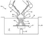
또 다른 쉘(72) 내에 다른 비계(71)를 포함하고 있는 또 다른 복합형 물체(70)를 제조하는 컴퓨터-제어 장치(50)의 변형예가 도 3에 도시되어 있다. 컴퓨터-제어 장치(50)는 제2 로봇 암(74)에 회전 가능하게 연결되어 있는 다른 플랫폼(73)을 포함한다. 이 플랫폼(73)은 하나 이상의 축 주위를 회전할 수 있되, 잠정적으로는 3개의 축 주위를 회전할 수 있다. 플랫폼(73)이 회전함에 따라, 제조 공정 중에 그 플랫폼(73) 위에 지지되어 있는 비계(71) 및 코어(72)가 상부 면(58)에 대해 기울어질 수 있게 되며, 잠정적으로는 이와 동시에 상부 면(58)에 대해 이동하게 된다. 이렇게 함으로써, 활성화 헤드(54)가 경화성 제1 재료(57)를 상부 면(58)에서 응고시켜, 물결 모양 또는 이중-곡선형태 부분들을 구비하는 비-평면형 비드 또는 층들을 형성하게 된다. 또한, 컴퓨터-제어 장치(50)에 의해 플랫폼(73)의 회전축이 상부 면(58)과 평행하게 위치하고, 동시에 활성화 헤드(54)가 회전하는 플랫폼(73)과 함께 작동하고 잠정적으로는 이동할 수 있다면, 활성화 헤드(54)에 의해 링 모양의 비드 및 나선형(helical)의 비드들이 제조될 수 있게 된다.A modification of the computer-controlled
도 4a 및 도 4b는, 적층 헤드(59)에 의해 적층되는 제2 재료로 형성되는 프레임(81)과 활성화 헤드(54)에 의해 응고되는 제1 재료로 형성되는 바디(82)를 포함하는 또 다른 복합형 물체(80)를 제조하는, 도 3에 도시되어 있는 컴퓨터-제어 장치(50)가 수행하는 두 단계를 설명하고 있다. 바디(82)는, 상부 면(58)에 대해 회전하는 플랫폼(73)과 활성화 헤드(54)의 작동에 의해 제조되는 비-평면형이며 곡선형태의 복수의 층들(85)을 포함한다.4A and 4B illustrate a further embodiment of the invention which comprises a
도 4a에서, 플랫폼(73)이 회전하여 복합형 요소(80)를 기울어지게 하고, 활성화 헤드(54)가 상부 면(58)에서 경화성 제1 재료(57)를 선택적으로 응고시켜, 비-평면형 층들(85) 중의 한 층을 제조한다. 그 결과, 프레임(81)의 일부분이 경화성 제1 재료(57) 안으로 잠기게 된다. 도 4b는 컴퓨터-제어 장치(50)의 다른 측면을 도시하고 있는데, 호스(84)를 통해 가스 볼륨과 연통하는 노즐(83)이 로봇 암(55)에 부착되어 있다. 플랫폼(73)이 회전하여 복합형 요소(80)를 바로 세우고, 노즐(83)이 경화성 제1 재료(57)로 덮여 있는 프레임(81) 부분들에 가스를 분사하여, 적층 헤드(59)로 다른 제2 재료를 적층하여 프레임(81)의 다른 부분들을 제조하기 전에 프레임(81)에서 경화성 제1 재료(57)의 적어도 일부를 제거하게 된다. 또는, 제2 재료의 또 다른 부분을 적층하기 전에 프레임(81)에서 액상의 경화성 제1 재료(57)를 비-파괴방식으로 제거하기 위해, 노즐(83)이 에너지원 또는 화학 작용제 공급부와 연통할 수 있다. 예를 들면, 프레임(81)에서 액상의 제1 재료를 제거하기 위해, 노즐(83)이 프레임(81)을 진동시키는 초음파 발신기를 포함할 수 있으며, 또는 노즐(83)이 프레임(81) 위에 표면장력 조절제를 분사할 수 있다.4A, the
도 5는 컴퓨터-제어 장치(50)에 의해 제조된 또 다른 복합형 물체(10)의 단면도이다. 복합형 물체(10)는 서로를 둘러싸고 있는 복수의 층들을 포함하고 있으며, 여기서, 내부 코어(11), 외부 코어(13) 및 쉘(15)은 경화성 제1 재료를 응고시켜 제조되고, 내부 필러(12) 및 외부 필러(14)는 적층 헤드(59)가 제2 및 제3 재료 공급부와 연통되어서 각각이 제2 및 제3 재료를 적층하여 제조된다. 제1, 제2 및 제3 재료는 서로 다른 물성을 구비해서, 복합형 물체(10)의 물성이 특정 기능 또는 미적 사양에 맞춰질 수 있게 된다. 예를 들면, 복합형 물체(10)가 충격 장벽(impact barrier)으로 작용하는 것으로 의도하는 경우, 제1 재료(57)가 경화될 때, 제1 재료는 세라믹 복합재료와 같은 강성 재료이고, 제2 및 제3 재료는 저밀도 및 고밀도 폴리우레탄 폼(foam)일 수 있다. 이렇게 함으로써, 복합형 물체(10)가 충격을 받을 때 그 힘이 복합형 물체(10)를 통해 전달되어 예상되는 방식으로 소산되게 된다.5 is a cross-sectional view of yet another
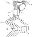
도 6은 컴퓨터-제어 장치(50)에 의해 제조되는 또 다른 복합형 물체(20)를 도시하고 있다. 복합형 물체(20)는 플랫폼(73) 위에 배치되는 지지 구조물(21), 상기 지지 구조물(21)로부터 연장하는 암에 고정되어 있는 타일(22) 및 상기 타일(20)에 접합되어 있는 바디(23)를 포함한다. 초기에 적층 헤드(59)로 제2 재료를 사용하여 지지 구조물(21)을 제조함으로써 복합형 물체(20)가 제조된다. 암들은 타일(22)과 결합하기에 적합하게 되어 있다. 타일(22)이 암들과 결합한다. 그런 다음, 활성화 헤드(54)에 의해, 각 타일(22)이 바디(23)와 접합하는 방식으로, 경화성 제1 재료를 응고시킨 비-평탄형 비드를 타일(22)을 가로지르며 배치함으로써, 바디(23)가 제조된다. 일단 바디(23)가 형성되면, 복합형 물체(20)를 저장소에서 꺼내어 배수시키고 지지 구조물(21)을 제거하여, 바디(23) 내에 매립되어 있는 타일(22)들을 노출시킨다. 제2 재료가 왁스 컴파운드 같이 용융되는 재료인 경우, 복합형 물체(20)를 가열하여 지지 구조물(21)을 용융시켜 제거할 수 있다. 이와 유사하게, 제2 재료가 석고와 같이 용해 가능한 재료라면, 지지 구조물(21)을 적당한 액체에 잠기게 하여 이를 달성할 수도 있다.Fig. 6 shows another
도 7은 제1 로봇 암(32)에 연결되어 있는 활성화 헤드(31) 및 제2 로봇 암(34)에 연결되어 있는 적층 헤드(33)를 구비하는 다른 장치(30)를 도시하고 있다. 양 로봇 암들(32, 34)은 상부 면(36)을 형성하는 액상의 경화성 제1 재료(35)의 저장소 위에 배치되어 있다. 활성화 헤드(31)는, 전술한 바와 같이 상부 면(36)에서 경화성 제1 재료(35)의 부분들을 선택적으로 응고시키기 위해 상부 면(36)에 대해 상대적으로 이동할 수 있으며 선택적으로 작동할 수 있다. 적층 헤드(33)는 파이버(38) 릴인 제2 재료 공급부와 연통하며, 파이버(38)를 토막 내고 이를 제1 재료(35) 내로 삽입하도록 선택적으로 작동할 수 있다.7 shows another
복수의 층들(37) 및 파이버들(38)을 포함하는 복합형 물체(39)를 제조하는 장치(30)가 도시되어 있다. 상부 면(36)에 제1 재료(35)를 응고시켜 비드를 형성함으로써, 활성화 헤드(31)가 층들(37)을 제조한다. 적층 헤드(33)가 활성화 헤드(31)를 추종하며, 제1 재료(35)가 경화되기 전인 '그린(green)(gel)' 상태에 있을 때, 제1 재료가 응고된 바로 직후의 하나 이상의 비드들 내로 토막 형태의 파이버들(38)을 분사한다. 제조 공정 중에, 비드들(37) 내로 개재된 파이버들(38)의 밀도가 장치(30)에 의해 조절되어서, 각 비드(37)의 밀도와 강성(rigidity)이 변화될 수 있다. 필요에 따라서는, 적층 헤드(33)는, 적층 헤드(33)가 적층하는 중에 혹은 적응한 바로 직후에, 파이버들(38)의 물성을 조절하기에 적합할 수 있다. 예를 들면, 이는, 강성을 증가시키기 위해 폴리머 파이버들(38)을 가열하거나 또는 파이버들(38)의 형상을 조절하고 파이버(38)와 비드 사이의 텐션을 증가시키기 위해 제1 재료가 그린 상태에 있는 동안에 비드 내에 매립되어 있는 형상기억합금 파이버(38)를 가열하는 것을 포함할 수 있다.There is shown an
도 8은 또 다른 복합형 물체(40)를 제조하는 변형된 장치(30)를 도시하고 있다. 장치(30)는 동일한 로봇 암(32)에 연결되어 있는 활성화 헤드(31)와 적층 헤드(33)를 구비한다. 플랫폼(39)에서부터 연장하는 지지 구조물(41)을 구비하는 플랫폼(39)이 상부 면(36) 아래에 위치하고 있다. 복합형 물체(40)를 제조하는 중에, 파이버들(38)이 장치(30)에 의해 지지 구조물(41)에 연결되어 있으며, 적층 헤드(38)로부터 감겨 있다. 활성화 헤드(31)가 적층 헤드(38)를 추종하며, 파이버(38)를 둘러싸는 경화성 제1 재료(35)의 비드들(42)을 응고시킨다. 이렇게 함으로써, 하나 이상의 연속된 파이버들(38)이 각 비드(42)의 전장을 따라 고정되게 된다. 파이버들(38)이 지지 구조물(41)에 고정되어 있기 때문에, 비드들(42)이 제조되기 전에 그리고 제조되는 동안에 파이버들(38)에 텐션이 가해질 수 있으며, 이에 의해 비드들(42)이 응고될 때, 복합형 물체(40)가 텐션을 받는 상태로 유지되게 된다. 필요에 따라서는, 추가의 지지 구조물(도시되어 있지 않음)이 플랫폼에서부터 연장하며, 이 추가의 지지 구조물은, 고정되어 텐션을 받고 있는 파이버들(38) 사이에서, 복합형 물체(40)의 다른 쪽 위에 제1 지지 구조물로부터 멀리 떨어져 배치된다. 바람직하기로는, 비드들(42)과의 체결을 돕기 위해, 파이버들에서 연장하는 일련의 결절들(도시하지 않음)을 구비하는 것과 같이, 파이버들(38)이 텍스쳐(textured) 되어 있다.Fig. 8 shows a modified
도 9는 장치(50)의 많은 구성요소(feature)들을 공유하는 또 다른 장치(110)를 도시하고 있다. 동일한 도면부호를 공유하는 구성요소들은 동일한 기능을 공유한다. 장치(110)는 저장소(56)에 대해 이동할 수 있는 2개의 로봇 암들(55, 112)을 구비한다. 제2 암(112)은 진공 시스템(도시되어 있지 않음)에 연결되어 있는 노즐(113)을 포함하며, 컴퓨터 지령에 응답하여 저장소(56)에서 액상의 경화성 재료(57)를 제거하도록 작동한다.Figure 9 shows another
복수의 공동(void)(116)을 구비하는 바디(115)를 포함하는 또 다른 물체(114)를 제조하는 과정에 있는 장치(110)가 도시되어 있다. 전술한 바와 같이, 경화성 제1 재료(57)를 선택적으로 응고시키는 활성화 헤드(54)에 의해 바디(115)가 제조된다. 바디(115)를 제조하는 중에, 제2 로봇 암(112)이 공동(116) 내에 갇혀 있는 액상의 경화성 재료(57)를 실질적으로 선택적으로 제거한다. 그런 다음, 적층 헤드(59)가 공동(116) 내로 제2 재료(117)를 선택적으로 적층한다.There is shown an
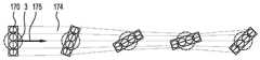
도 10a는 장치(50)의 또 다른 측면을 도시하고 있다. 활성화 헤드(54)는 에너지원과 연통하며, 에너지원을 상부 면(58) 위로 선택적으로 초점을 맞추게 하기에 적합한 복수의 노즐들(170)을 구비하여, 경화성 재료(57)의 부분들(171)을 응고시킨다. 노즐들(170)은 선형 어레이로 배치되어 있으며, 상부 면(58)과 실질적으로 직교하는 로봇 암(55)에 의해 배치되는 축선 주위를 회전할 수 있다. 활성화 헤드(54)가 상부 면(58)을 가로지르며 이동하기 때문에, 노즐들(170) 어레이가 활성화 헤드(54)가 이동하는 방향에 대해 회전하는 동안에도, 노즐들(170)과 상부 면(58) 사이의 이격 거리가 유지되게 된다. 노즐들(170)은 최대 3개의 비드들(171)이 동시에 제조될 수 있도록 선택적으로 작동할 수 있다. 이는 응고된 비드들(170) 간에 캐비티(172)를 형성하기 이해 노즐들(170) 중 이루를 선택적으로 작동시키지 않는 것을 포함할 수 있다.FIG. 10A shows another aspect of the
도 10b는 활성화 헤드(54)가 상부 면(58)을 가로지는 제1 방향(175)으로의 경로를 따라 이동하며 각 노즐(170)을 동시에 작동시킴으로써, 경화성 재료(57)의 대응 부분(174)을 응고시키는 구성이 도시되어 있다. 활성화 헤드(54)가 그 경로를 따라 이동하는 동안에, 노즐들 어레이가 제1 방향에 대해 회전하여, 응고되는 부분(174)의 폭이 감소되며, 이에 의해 제조되는 중에 응고되는 부분(174)의 폭이 연속적으로 그리고 부드럽게 변할 수 있게 된다. 에너지의 순(net) 노출 강도가 일정하고 이에 따라 경화성 재료(174)를 일관된 깊이만큼 응고시킨다고 가정하면, 각 노즐(170)에 의한 에너지의 노출 강도가 응고되는 부분(174)을 제조하는 동안에 변할 수 있다. 예를 들면, 노즐들(170) 어레이가 얇은 부분을 제조하기 위해 회전함에 따라, 모든 노즐들(170)의 노출 강도가 감소되게 된다. 반대로, 노즐들(170) 어레이가 곡선 경로(도시되어 있지 않음) 주위를 이동할 때, 그 곡선 경로의 바깥쪽에 배치되어 있는 노즐(170)은, 안쪽에 배치되어 있는 노즐(170)보다 더 큰 강도를 노출하게 된다. 필요에 따라서는, 노즐들(170)이 각 노즐들(170)의 형상이 조절될 수 있도록(도시되어 있지 않음) 그리고 각 노즐(170)이 회전될 수 있도록 수정될 수 있다.Figure 10B illustrates a process in which the activating
도 11은 장치(50)와 관련하여 사용되는 고정판(160)을 도시하고 있다. 고정판(160)은 플랫폼(61)에 고정되어 있으며, 제1 또는 제2 재료와 플랫폼(61)의 체결을 돕기 위해, 돌출부들 및/또는 리세스들을 구비하는 하나 이상의 나선형 고정물(161) 및/또는 텍스쳐된 영역(162)을 제공한다. 고정판(160)은 플랫폼(61)에 착탈 가능한 방식으로 고정될 수 있으며, 제조되는 물체에 영구적으로 고정된다. 제조 공정 중에, 나선형 바(163) 같은 추가의 부착물들이 나선형 고정물(161)에 고정되어, 제조되는 물체 내의 고정부 전장으로 연장한다.Fig. 11 shows a
도 12a 내지 도 12e는 또 다른 물체(164)를 제조하는 장치(20)의 다양한 제조 단계 중에, 플랫폼(61)에 부착되어 있는 고정판(160)을 도시하고 있다. 도 12a는 복수의 기계적 고정구(165)에 의해 플랫폼(61)에 연결되어 있는 고정판(160)을 도시하고 있다. 도 12b는 고정판(160), 나선형 고정물(161) 및 천공형 영역(162)과 접촉하며 제조되어 있는 제품(164)의 다수의 층들을 도시하고 있다. 확장 로드(extender rod)(163)와 부하 스프레딩 고정구(load spreading fixture)(169)가 상기 나선형 고정구(161)의 일부에 또한 연결되어 있다. 도 12c는 제조 공정의 후속 단계를 도시하고 있으며, 여기서 플랫폼(61)이 회전하여 고정판(160)과 체결되어 있는 물체(164)가 기울어지게 된다. 도 12d는 추가의 나선형 고정물(167)에 의해 추가의 고정판(166)이 완성된 제품(164)의 상면에 연결되어 있는 최종 제품(164)을 도시하고 있다. 각각이 분리 가능한 인양 고정물(168)들이 나선형 고정물(167)에 연결되어 있다. 도 12e는 플랫폼(61)에서 분리된 물체(164)를 도시하고 있다. 양 고정판(160)들이 제품(164)에 체결되어 있다.12A-12E illustrate a securing
본 발명의 사상에 따라 본 발명에 대해 변형 또는 변조가 이루어질 수 있음은 자명하며, 이러한 변형 또는 변조는 본 발명의 일부가 된다. 위에서 특정 실시형태들을 참고하여 본 발명을 설명하였지만, 본 발명이 이들 실시형태들만으로 한정되는 것이 아니고 다른 형태로 구현될 수 있다는 점도 이해해야 한다.It will be appreciated that modifications and variations can be made to the invention in accordance with the teachings of the present invention, and such modifications or alterations are part of the invention. While the present invention has been described with reference to particular embodiments, it is to be understood that the invention is not limited to only those embodiments, but may be otherwise embodied.
Claims (22)
Translated fromKorean상기 장치에 의해 복합형 물체 형상과 관련된 컴퓨터 지령을 수신하는 단계;
복합형 물체 형상에 대응되는 특정 지점에 제2 재료 부분들을 적층하기 위해 적층 헤드를 이동시키고 선택적으로 작동시키는 단계;
복합형 물체 형상에 대응되는 특정 지점에 제1 재료 부분들을 응고시키기 위해 활성화 헤드를 이동시키고 선택적으로 작동시키는 단계;를 포함하되,
제1 재료의 경화된 부분들과 제2 재료의 적층된 부분들이 복합형 물체를 형성하는 것을 특징으로 하는 복합형 물체 제조 방법.A reservoir for storing a first material that is substantially liquid and curable, an activation head for coagulating the first material, and a laminating head in communication with the second material supply, wherein the activation head and the laminating head are positioned relative to the reservoir A method of manufacturing a hybrid object using a moveable computer-controlled device, the method comprising:
Receiving a computer command related to the hybrid object shape by the apparatus;
Moving and selectively operating the stacking head to stack the second material portions at a particular point corresponding to the composite object shape;
Moving and selectively activating the activation head to solidify the first material portions at a particular point corresponding to the composite object shape,
Wherein the cured portions of the first material and the laminated portions of the second material form a composite body.
상기 장치가 제1 재료의 경화된 부분들과 제2 재료의 적층된 부분들을 지지하며, 상기 저장소에 대해 상대 이동이 가능한 플랫폼을 추가로 포함하고, 적층 헤드를 이동시키고 선택적으로 작동시키는 단계와 활성화 헤드를 이동시키고 선택적으로 작동시키는 단계 중 적어도 하나의 단계가 플랫폼에 인접하게 제1 재료 또는 제2 재료를 제조하는 단계를 추가로 포함하는 것을 특징으로 하는 복합형 물체 제조 방법.The method according to claim 1,
The apparatus further comprising a platform that supports cured portions of the first material and laminated portions of the second material and is capable of relative movement relative to the reservoir, Wherein at least one of the step of moving and selectively actuating the head further comprises the step of fabricating a first material or a second material adjacent the platform.
상기 저장소에 대해 상기 플랫폼을 상대 이동 시키는 단계를 추가로 포함하여, 그 플랫폼 위에 지지되어 있는 제1 재료의 응고된 부분들과 제2 재료의 적층된 부분들이 이동되는 것을 특징으로 하는 복합형 물체 제조 방법.3. The method of claim 2,
Further comprising moving the platform relative to the reservoir such that the solidified portions of the first material supported on the platform and the laminated portions of the second material are moved. Way.
제1 재료가 상부를 형성하고, 활성화 헤드를 이동시키고 선택적으로 작동시키는 단계가 상기 상부 면에서 제1 재료의 부분들을 응고시키는 단계를 추가로 포함하는 것을 특징으로 하는 복합형 물체 제조 방법.The method according to claim 2 or 3,
Further comprising the step of allowing the first material to form the top and the step of moving and selectively actuating the activation head to solidify portions of the first material at the top surface.
상부 면 위로 플랫폼을 이동시키는 추가의 초기 단계를 포함하고, 적층 헤드를 이동시키고 선택적으로 작동시키는 단계가 적어도 부분적으로 플랫폼에 인접하게 제2 재료의 부분들을 적층시키는 단계를 추가로 포함하는 것을 특징으로 하는 복합형 물체 제조 방법.5. The method of claim 4,
Further comprising the additional initial step of moving the platform over the top surface, wherein moving and selectively actuating the lamination head further comprises laminating portions of the second material at least partially adjacent to the platform Of the composite material.
적층 헤드를 이동 및 선택적으로 작동한 후에, 제2 재료의 적층된 부분 위치로 플랫폼을 상부 면에 대해 상대 이동시키는 단계를 추가로 포함하는 것을 특징으로 하는 복합형 물체 제조 방법.6. The method of claim 5,
Further comprising moving the platform relative to the top surface to a stacked partial location of the second material after moving and selectively operating the lamination head.
활성화 헤드를 이동 및 선택적으로 작동한 후에, 제1 재료의 응고된 부분 위치 및 제2 재료의 적층된 부분 위치로 플랫폼을 상부 면에 대해 상대 이동시키는 단계를 추가로 포함하는 것을 특징으로 하는 복합형 물체 제조 방법.The method according to claim 6,
Further comprising moving the platform relative to the upper surface with the solidified portion location of the first material and the stacked portion location of the second material after moving and selectively operating the activation head Method of manufacturing an object.
적층 헤드를 이동 및 선택적으로 작동시키는 단계와 활성화 헤드를 이동 및 선택적으로 작동시키는 단계가 반복되는 것을 특징으로 하는 복합형 물체 제조 방법.10. A method according to any one of the preceding claims,
Wherein the step of moving and selectively actuating the lamination head and the step of moving and selectively actuating the activation head are repeated.
적층 헤드를 이동 및 선택적으로 작동시키는 단계와 활성화 헤드를 이동 및 선택적으로 작동시키는 단계가 동시에 수행되는 것을 특징으로 하는 복합형 물체 제조 방법.10. A method according to any one of the preceding claims,
Wherein the step of moving and selectively operating the lamination head and the step of moving and selectively actuating the activation head are simultaneously performed.
적층 헤드를 이동 및 선택적으로 작동시키는 단계, 활성화 헤드를 이동 및 선택적으로 작동시키는 단계, 및 플랫폼을 이동시키는 단계들 중 적어도 두 단계가 동시에 수행되는 것을 특징으로 하는 복합형 물체 제조 방법.The method of claim 3,
Wherein at least two of the steps of moving and selectively operating the lamination head, moving and selectively actuating the activation head, and moving the platform are performed simultaneously.
플랫폼이 하나 이상의 축선 주위로 회전 가능하고, 플랫폼을 이동시키는 단계가 플랫폼을 회전시키는 단계를 추가로 포함하는 것을 특징으로 하는 복합형 물체 제조 방법.The method of claim 3,
Wherein the platform is rotatable about one or more axes, and wherein moving the platform further comprises rotating the platform.
상부 면을 형성하는 실질적으로 액체이며 경화성인 제1 재료를 저장하는 저장소;
상기 저장소에 대해 상대 이동할 수 있으며, 제1 재료를 응고시키기 위한 활성화 헤드;
상기 저장소에 대해 상대 이동할 수 있으며, 제2 재료 공급부와 연통하는 적층 헤드; 및
복합형 물체의 형상과 관련된 컴퓨터 지령에 응답하여 활성화 헤드 및 적층 헤드를 이동 및 작동시키도록 구성된 컨트롤러;를 포함하고,
상기 컨트롤러는 복합형 물체 형상에 대응되는 특정 지점에 제1 재료 부분들을 응고시키기 위해 활성화 헤드를 이동 및 선택적으로 작동시키고, 그리고 상기 컨트롤러는 복합형 물체 형상에 대응되는 특정 지점에 제2 재료를 적층시키기 위해 적층 헤드를 이동 및 선택적으로 작동시키는 것을 특징으로 하는 복합형 물체를 제조하기 위한 컴퓨터-제어 장치.A computer-controlled apparatus for manufacturing a hybrid object, the apparatus comprising:
A reservoir for storing a first material that is substantially liquid and curable to form a top surface;
An activation head movable relative to the reservoir and for coagulating the first material;
A stacking head movable relative to the reservoir and in communication with the second material supply; And
And a controller configured to move and activate the activation head and the lamination head in response to a computer command related to the shape of the composite object,
The controller moves and selectively actuates the activation head to solidify the first material portions at a particular point corresponding to the composite object shape and the controller is configured to stack the second material at a particular point corresponding to the composite object shape Wherein the stacking head is moved and selectively operated to bring the stacking head into operation.
제1 재료의 응고된 부분들과 제2 재료의 적층된 부분들을 지지하며, 상기 저장소에 대해 상대 이동할 수 있는 플랫폼을 추가로 포함하는 것을 특징으로 하는 복합형 물체를 제조하기 위한 컴퓨터-제어 장치.13. The method of claim 12,
Further comprising a platform that supports the coagulated portions of the first material and the stacked portions of the second material and that is movable relative to the reservoir.
상기 컨트롤러가 상기 플랫폼을 이동시키도록 구성되고, 상기 컨트롤러는 컴퓨터 지령에 따라 플랫폼을 활성화 헤드, 적층 헤드 및 상부 면들 중 하나 이상에 대해 상대 이동시키는 것을 특징으로 하는 복합형 물체를 제조하기 위한 컴퓨터-제어 장치.13. The method of claim 12,
Wherein the controller is configured to move the platform and the controller moves the platform relative to at least one of the activation head, the lamination head, and the upper surfaces in accordance with a computer command, controller.
플랫폼이 하나 이상의 축선 주위로 회전할 수 있고, 상기 컨트롤러는 컴퓨터 지령에 따라 플랫폼을 회전시키도록 구성되는 것을 특징으로 하는 복합형 물체를 제조하기 위한 컴퓨터-제어 장치.14. The method of claim 13,
Wherein the platform is rotatable about one or more axes and the controller is configured to rotate the platform in accordance with a computer command.
가스 공급부와 연통하는 분사 노즐을 추가로 포함하고, 상기 컨트롤러는 컴퓨터 지령에 따라 가스를 배출하도록 분사 노즐을 선택적으로 작동시키도록 구성되는 것을 특징으로 하는 복합형 물체를 제조하기 위한 컴퓨터-제어 장치.16. The method of claim 15,
Further comprising a spray nozzle in communication with the gas supply, wherein the controller is configured to selectively actuate the spray nozzle to discharge gas according to a computer command.
제2 재료가 파이버 릴이고, 적층 헤드는 파이버 릴을 배치시키기에 적합하며, 상기 컨트롤러는 파이버 릴을 배치시키기 위해 적층 헤드를 선택적으로 작동시키도록 구성된 것을 특징으로 하는 복합형 물체를 제조하기 위한 컴퓨터-제어 장치.13. The method of claim 12,
Characterized in that the second material is a fiber reel, the lamination head is suitable for disposing a fiber reel, and the controller is configured to selectively operate the lamination head to dispose a fiber reel. -controller.
적층 헤드는 파이버 릴을 토막(section)으로 절단하여 이들 토막을 적층 헤드로부터 분사시키기에 적합한 것을 특징으로 하는 복합형 물체를 제조하기 위한 컴퓨터-제어 장치.18. The method of claim 17,
Wherein the lamination head is adapted to cut the fiber reel into sections and to jet these laminations from the laminating head.
진공 소스와 연통하는 흡입 노즐을 추가로 포함하고, 상기 컨트롤러는 저장소 및 복합형 물체 중 하나 이상으로부터 제1 재료를 제거하도록 상기 흡입 노즐을 선택적으로 작동시키도록 구성되는 것을 특징으로 하는 복합형 물체를 제조하기 위한 컴퓨터-제어 장치.13. The method of claim 12,
Further comprising a suction nozzle in communication with the vacuum source, wherein the controller is configured to selectively actuate the suction nozzle to remove the first material from at least one of the reservoir and the composite object. Computer-controlled apparatus for manufacturing.
활성화 헤드가 활성화 헤드 어레이를 포함하고, 상기 활성화 헤드 어레이는 하나 이상의 축선 주위로 회전할 수 있으며, 상기 컨트롤러는 컴퓨터 지령에 따라 각 노즐을 선택적으로 작동시키고 활성화 헤드 어레이를 회전시키도록 구성되는 것을 특징으로 하는 복합형 물체를 제조하기 위한 컴퓨터-제어 장치.13. The method of claim 12,
The activation head comprising an activation head array, the activation head array being rotatable about one or more axes, the controller being configured to selectively actuate each nozzle according to a computer command and to rotate the activation head array Wherein the computer-controlled apparatus is a computer-controlled apparatus for producing a hybrid object.
플랫폼에 착탈 가능하게 연결되기에 적합한 고정판을 추가로 포함하고, 고정판이 복합형 물체와 체결하기 위한 하나 이상의 체결부를 구비하는 것을 특징으로 하는 복합형 물체를 제조하기 위한 컴퓨터-제어 장치.14. The method of claim 13,
Further comprising a fastening plate adapted to be detachably connected to the platform, the fastening plate having at least one fastening portion for fastening the fastening plate to the composite type object.
하나 이상의 체결부가 나선형 고정물을 포함하는 것을 특징으로 하는 복합형 물체를 제조하기 위한 컴퓨터-제어 장치.22. The method of claim 21,
Characterized in that the at least one fastening part comprises a spiral fixture.
Applications Claiming Priority (3)
| Application Number | Priority Date | Filing Date | Title |
|---|---|---|---|
| AU2014901005 | 2014-03-21 | ||
| AU2014901005AAU2014901005A0 (en) | 2014-03-21 | Method for fabricating an object | |
| PCT/AU2015/050127WO2015139095A1 (en) | 2014-03-21 | 2015-03-23 | Method and apparatus for fabricating a composite object |
Publications (1)
| Publication Number | Publication Date |
|---|---|
| KR20160136408Atrue KR20160136408A (en) | 2016-11-29 |
Family
ID=54143557
Family Applications (1)
| Application Number | Title | Priority Date | Filing Date |
|---|---|---|---|
| KR1020167029468AAbandonedKR20160136408A (en) | 2014-03-21 | 2015-03-23 | Method and apparatus for fabricating a composite object |
Country Status (8)
| Country | Link |
|---|---|
| US (2) | US10293594B2 (en) |
| EP (1) | EP3119588B1 (en) |
| JP (1) | JP6628737B2 (en) |
| KR (1) | KR20160136408A (en) |
| CN (2) | CN106457664B (en) |
| AU (1) | AU2015234244B2 (en) |
| CA (1) | CA2979003A1 (en) |
| WO (1) | WO2015139095A1 (en) |
Families Citing this family (83)
| Publication number | Priority date | Publication date | Assignee | Title |
|---|---|---|---|---|
| US9186848B2 (en) | 2013-03-22 | 2015-11-17 | Markforged, Inc. | Three dimensional printing of composite reinforced structures |
| US9688028B2 (en) | 2013-03-22 | 2017-06-27 | Markforged, Inc. | Multilayer fiber reinforcement design for 3D printing |
| CN107187022B (en) | 2013-03-22 | 2020-08-11 | 格雷戈里·托马斯·马克 | Three-dimensional printing |
| US9126365B1 (en) | 2013-03-22 | 2015-09-08 | Markforged, Inc. | Methods for composite filament fabrication in three dimensional printing |
| US9694544B2 (en) | 2013-03-22 | 2017-07-04 | Markforged, Inc. | Methods for fiber reinforced additive manufacturing |
| US9149988B2 (en) | 2013-03-22 | 2015-10-06 | Markforged, Inc. | Three dimensional printing |
| US10259160B2 (en) | 2013-03-22 | 2019-04-16 | Markforged, Inc. | Wear resistance in 3D printing of composites |
| US9579851B2 (en) | 2013-03-22 | 2017-02-28 | Markforged, Inc. | Apparatus for fiber reinforced additive manufacturing |
| US9956725B2 (en) | 2013-03-22 | 2018-05-01 | Markforged, Inc. | Three dimensional printer for fiber reinforced composite filament fabrication |
| US9156205B2 (en)* | 2013-03-22 | 2015-10-13 | Markforged, Inc. | Three dimensional printer with composite filament fabrication |
| US9186846B1 (en) | 2013-03-22 | 2015-11-17 | Markforged, Inc. | Methods for composite filament threading in three dimensional printing |
| US11237542B2 (en) | 2013-03-22 | 2022-02-01 | Markforged, Inc. | Composite filament 3D printing using complementary reinforcement formations |
| US10682844B2 (en) | 2013-03-22 | 2020-06-16 | Markforged, Inc. | Embedding 3D printed fiber reinforcement in molded articles |
| US9815268B2 (en) | 2013-03-22 | 2017-11-14 | Markforged, Inc. | Multiaxis fiber reinforcement for 3D printing |
| US11981069B2 (en) | 2013-03-22 | 2024-05-14 | Markforged, Inc. | Three dimensional printing of composite reinforced structures |
| US10953609B1 (en) | 2013-03-22 | 2021-03-23 | Markforged, Inc. | Scanning print bed and part height in 3D printing |
| EP3130444B1 (en) | 2013-06-05 | 2020-04-01 | Markforged, Inc. | Method for fiber reinforced additive manufacturing |
| GB201314030D0 (en)* | 2013-08-06 | 2013-09-18 | Eads Uk Ltd | Extrusion-Based Additive Manufacturing System and Method |
| WO2015084422A1 (en) | 2013-12-05 | 2015-06-11 | Massachusetts Institute Of Technology | Object of additive manufacture with encoded predicted shape change |
| WO2016057853A1 (en) | 2014-10-08 | 2016-04-14 | Massachusetts Institute Of Technology | Self-transforming structures |
| CN107428096B (en)* | 2015-03-03 | 2020-01-17 | 飞利浦照明控股有限公司 | 3D printed object and method for producing a 3D printed object |
| US10071546B2 (en)* | 2015-06-05 | 2018-09-11 | Collider, Inc. | Apparatus and method for hybrid manufacturing |
| ES2559114B1 (en)* | 2015-10-19 | 2016-09-28 | Goratu Máquinas Herramienta, S.A. | Material deposition machine for manufacturing parts |
| US20170120535A1 (en)* | 2015-11-03 | 2017-05-04 | Massachusetts Institute Of Technology | Actuatable Assemblies Fabricatable by Deposition of Solidifying and Non-Solidifying Materials |
| DE102015122647A1 (en)* | 2015-12-22 | 2017-06-22 | Arburg Gmbh + Co. Kg | Device and method for producing a three-dimensional object with a fiber feed device |
| JP2017165035A (en)* | 2016-03-17 | 2017-09-21 | 富士ゼロックス株式会社 | Lamination shaping apparatus |
| US10486364B2 (en)* | 2016-05-03 | 2019-11-26 | Xerox Corporation | System and method for forming integrated interfaces within a three-dimensionally printed object with different build materials |
| US11052597B2 (en) | 2016-05-16 | 2021-07-06 | Massachusetts Institute Of Technology | Additive manufacturing of viscoelastic materials |
| JP6998111B2 (en)* | 2016-08-03 | 2022-01-18 | 住友ゴム工業株式会社 | Gaskets applied to medical syringes |
| EP4049828B1 (en) | 2016-09-22 | 2024-01-03 | University of South Alabama | Method for 3d printing |
| WO2018055522A1 (en) | 2016-09-22 | 2018-03-29 | Stratasys Ltd. | Formulation, method and system for solid freeform fabrication |
| KR20190058527A (en) | 2016-09-22 | 2019-05-29 | 스트라타시스 엘티디. | Method and system for making arbitrary shape |
| CA3039851A1 (en) | 2016-10-21 | 2018-04-26 | Mosaic Manufacturing Ltd. | Joiners, methods of joining, and related systems for additive manufacturing |
| US10723075B2 (en) | 2016-11-02 | 2020-07-28 | R3 Printing, Inc. | System and method for automated successive three-dimensional printing |
| US11660819B2 (en) | 2016-11-02 | 2023-05-30 | R3 Printing, Inc. | System and method for automated successive three-dimensional printing |
| DE102016222658A1 (en)* | 2016-11-17 | 2018-05-17 | Bayerische Motoren Werke Aktiengesellschaft | Apparatus and method for producing a fiber-reinforced component of a fiber-reinforced core and at least one additive applied to the fiber-reinforced core plastic portion, and fiber-reinforced component |
| DE102016122131A1 (en)* | 2016-11-17 | 2018-05-17 | Weeke Bohrsysteme Gmbh | Method for producing a component and device |
| US20200009769A1 (en) | 2016-12-14 | 2020-01-09 | Covestro Deutschland Ag | Method for producing a 3d printed, foam-filed object |
| US10633772B2 (en) | 2017-01-12 | 2020-04-28 | Massachusetts Institute Of Technology | Active woven materials |
| US10549505B2 (en) | 2017-01-12 | 2020-02-04 | Massachusetts Institute Of Technology | Active lattices |
| US20180200962A1 (en) | 2017-01-13 | 2018-07-19 | General Electric Company | Additive manufacturing using a dynamically grown build envelope |
| US10022794B1 (en) | 2017-01-13 | 2018-07-17 | General Electric Company | Additive manufacturing using a mobile build volume |
| US9956612B1 (en)* | 2017-01-13 | 2018-05-01 | General Electric Company | Additive manufacturing using a mobile scan area |
| US10022795B1 (en) | 2017-01-13 | 2018-07-17 | General Electric Company | Large scale additive machine |
| US10478893B1 (en) | 2017-01-13 | 2019-11-19 | General Electric Company | Additive manufacturing using a selective recoater |
| US10857726B2 (en)* | 2017-01-24 | 2020-12-08 | Continuous Composites Inc. | Additive manufacturing system implementing anchor curing |
| US10953605B2 (en) | 2017-04-04 | 2021-03-23 | Massachusetts Institute of Technology, Cambridge, Massachusetts and Steeicase Incorporated | Additive manufacturing in gel-supported environment |
| EP3417961B1 (en)* | 2017-06-19 | 2022-07-27 | General Electric Company | Additive manufacturing fixture |
| US11465356B2 (en)* | 2017-06-20 | 2022-10-11 | Toray Engineering Co., Ltd. | Method for predicting strength of structure, method for modeling structure, support method for additive manufacturing of structure, and recording medium |
| DE102017214578A1 (en)* | 2017-08-22 | 2019-02-28 | Robert Bosch Gmbh | A method of manufacturing a molded component, and a molded component made by such a method |
| WO2019059803A1 (en)* | 2017-09-25 | 2019-03-28 | Siemens Aktiengesellschaft | Additive manufacturing technique for manufacturing articles with composite structures |
| US10766195B2 (en)* | 2017-10-05 | 2020-09-08 | The Boeing Company | Additive manufacturing fiber composites and related systems and methods |
| US11565468B1 (en)* | 2017-12-07 | 2023-01-31 | Redwire Space, Inc. | System and method for hybrid additive and subtractive manufacturing with dimensional verification |
| US10569474B2 (en)* | 2018-01-09 | 2020-02-25 | Arevo, Inc. | Free-space 3D printer |
| JP6938398B2 (en)* | 2018-02-09 | 2021-09-22 | 東レエンジニアリング株式会社 | Three-dimensional modeling method |
| US11130284B2 (en)* | 2018-04-12 | 2021-09-28 | Continuous Composites Inc. | System and head for continuously manufacturing composite structure |
| CA3100846C (en)* | 2018-06-11 | 2023-08-01 | Local Motors IP, LLC | Additively manufactured structure and method for making the same |
| WO2020017405A1 (en)* | 2018-07-19 | 2020-01-23 | 株式会社ニコン | Shaping system |
| EP3856487A1 (en) | 2018-09-28 | 2021-08-04 | Stratasys Ltd. | Three-dimensional inkjet printing of a thermally stable object |
| EP3856486B1 (en)* | 2018-09-28 | 2025-05-28 | Stratasys Ltd. | Method for additive manufacturing with partial curing |
| WO2020075198A2 (en)* | 2018-10-10 | 2020-04-16 | Indian Institute Of Technology Bombay | Multi-station multi-axis hybrid layered manufacturing system |
| DE102018126704A1 (en)* | 2018-10-25 | 2020-04-30 | Bayerische Motoren Werke Aktiengesellschaft | Method and device for producing a fiber composite component by means of a 3D printing method |
| US11312071B2 (en) | 2018-11-12 | 2022-04-26 | Ossur Iceland Ehf | Additive manufacturing system, method and corresponding components for making elastomeric structures |
| KR101978996B1 (en)* | 2018-12-11 | 2019-05-17 | 주식회사 쓰리딜라이트 | A 3D Printer For Minimum Support |
| CN111409266A (en)* | 2019-01-06 | 2020-07-14 | 严铜 | Easily-stripped supporting material and 3D printer using same |
| DE102019111620A1 (en)* | 2019-05-06 | 2020-11-12 | Hochschule Aalen | Device and method for additive manufacturing of a three-dimensional object |
| DE102019116230A1 (en)* | 2019-06-14 | 2020-12-17 | Airbus Operations Gmbh | Method and system for making a structure holder |
| CN110641017B (en)* | 2019-09-24 | 2021-09-28 | 山东中科智能设备有限公司 | 3D printer structure and supporting printing method thereof |
| EP4057947A1 (en) | 2019-11-12 | 2022-09-21 | Ossur Iceland Ehf | Ventilated prosthetic liner |
| JP2023503478A (en)* | 2019-11-26 | 2023-01-30 | オルボテック リミテッド | Method and system for manufacturing three-dimensional electronic products |
| US20210276688A1 (en)* | 2020-03-06 | 2021-09-09 | Galactic Co., LLC | Shaped Composite Vehicle Skins and Method for High Rate Manufacturing of Same |
| EP3957480A1 (en)* | 2020-08-21 | 2022-02-23 | Siemens Aktiengesellschaft | Assembly for material extrusion for the additive manufacturing of a three-dimensional object |
| FR3116461B1 (en)* | 2020-11-26 | 2022-12-23 | S A S 3Dceram Sinto | Machine for manufacturing raw parts in ceramic or metallic material |
| JP7600672B2 (en)* | 2020-12-23 | 2024-12-17 | セイコーエプソン株式会社 | Three-dimensional object printing device and three-dimensional object printing method |
| JP7308240B2 (en)* | 2021-06-24 | 2023-07-13 | 株式会社Nba | 3D printer |
| CN113547747A (en)* | 2021-08-12 | 2021-10-26 | 杭州捷诺飞生物科技股份有限公司 | Thermosetting printing method and printing device thereof |
| US12390989B2 (en)* | 2022-02-11 | 2025-08-19 | University Of Florida Research Foundation, Incorporated | Methods and apparatuses for hollow and multi-material stereolithography |
| DE102022105591A1 (en) | 2022-03-10 | 2023-09-14 | Bayerische Motoren Werke Aktiengesellschaft | Method and system for producing a structural component |
| WO2023223528A1 (en)* | 2022-05-20 | 2023-11-23 | スターテクノ株式会社 | Three-dimensional printing device |
| CN115489114A (en)* | 2022-07-29 | 2022-12-20 | 广东工业大学 | Ultrasonic additive manufacturing method and device for continuous fiber reinforced composite material |
| JP7585270B2 (en)* | 2022-10-05 | 2024-11-18 | 株式会社ソディック | Layered modeling device, three-dimensional object manufacturing method, and teaching method |
| WO2024149579A1 (en)* | 2023-01-12 | 2024-07-18 | Saeki Robotics Ag | Manufacture of three-dimensional objects |
| US20240367387A1 (en)* | 2023-05-04 | 2024-11-07 | Battelle Savannah River Alliance, Llc | Method of controlling local environment exposure during additive manufacturing |
Family Cites Families (18)
| Publication number | Priority date | Publication date | Assignee | Title |
|---|---|---|---|---|
| US4575330A (en)* | 1984-08-08 | 1986-03-11 | Uvp, Inc. | Apparatus for production of three-dimensional objects by stereolithography |
| US5263130A (en)* | 1986-06-03 | 1993-11-16 | Cubital Ltd. | Three dimensional modelling apparatus |
| JPH0336019A (en)* | 1989-07-03 | 1991-02-15 | Brother Ind Ltd | Three-dimensional molding method and device |
| US5143817A (en) | 1989-12-22 | 1992-09-01 | E. I. Du Pont De Nemours And Company | Solid imaging system |
| US5094935A (en)* | 1990-06-26 | 1992-03-10 | E. I. Dupont De Nemours And Company | Method and apparatus for fabricating three dimensional objects from photoformed precursor sheets |
| DE10018987A1 (en)* | 2000-04-17 | 2001-10-31 | Envision Technologies Gmbh | Device and method for producing three-dimensional objects |
| US6611053B2 (en)* | 2000-06-08 | 2003-08-26 | Micron Technology, Inc. | Protective structure for bond wires |
| US6786711B2 (en) | 2001-06-08 | 2004-09-07 | The United States Of America As Represented By The Secretary Of The Navy | Method and system for production of fibrous composite prototypes using acoustic manipulation in stereolithography |
| TW561102B (en)* | 2001-10-22 | 2003-11-11 | Hrl Lab Llc | Preparing composites by using resins |
| GB0715164D0 (en)* | 2007-08-06 | 2007-09-12 | Airbus Uk Ltd | Method and apparatus for manufacturing a composite material |
| JP2009101565A (en)* | 2007-10-23 | 2009-05-14 | Seiko Epson Corp | Method for manufacturing three-dimensional structure and apparatus for manufacturing the same |
| US9457521B2 (en)* | 2011-09-01 | 2016-10-04 | The Boeing Company | Method, apparatus and material mixture for direct digital manufacturing of fiber reinforced parts |
| EP2666617B1 (en)* | 2012-05-23 | 2017-07-05 | AIRBUS HELICOPTERS DEUTSCHLAND GmbH | A method of producing toughened composite structures |
| US9511543B2 (en)* | 2012-08-29 | 2016-12-06 | Cc3D Llc | Method and apparatus for continuous composite three-dimensional printing |
| CN107187022B (en)* | 2013-03-22 | 2020-08-11 | 格雷戈里·托马斯·马克 | Three-dimensional printing |
| EP3130444B1 (en)* | 2013-06-05 | 2020-04-01 | Markforged, Inc. | Method for fiber reinforced additive manufacturing |
| US9796140B2 (en)* | 2014-06-19 | 2017-10-24 | Autodesk, Inc. | Automated systems for composite part fabrication |
| US10857726B2 (en)* | 2017-01-24 | 2020-12-08 | Continuous Composites Inc. | Additive manufacturing system implementing anchor curing |
- 2015
- 2015-03-23KRKR1020167029468Apatent/KR20160136408A/ennot_activeAbandoned
- 2015-03-23CACA2979003Apatent/CA2979003A1/ennot_activeAbandoned
- 2015-03-23AUAU2015234244Apatent/AU2015234244B2/ennot_activeCeased
- 2015-03-23JPJP2016559175Apatent/JP6628737B2/ennot_activeExpired - Fee Related
- 2015-03-23CNCN201580024321.8Apatent/CN106457664B/ennot_activeExpired - Fee Related
- 2015-03-23USUS15/127,858patent/US10293594B2/ennot_activeExpired - Fee Related
- 2015-03-23CNCN201711069503.4Apatent/CN107627595A/enactivePending
- 2015-03-23WOPCT/AU2015/050127patent/WO2015139095A1/enactiveApplication Filing
- 2015-03-23EPEP15764969.0Apatent/EP3119588B1/enactiveActive
- 2019
- 2019-05-16USUS16/414,084patent/US10821659B2/ennot_activeExpired - Fee Related
Also Published As
| Publication number | Publication date |
|---|---|
| CN106457664A (en) | 2017-02-22 |
| JP6628737B2 (en) | 2020-01-15 |
| AU2015234244B2 (en) | 2019-09-19 |
| CA2979003A1 (en) | 2015-09-24 |
| JP2017509514A (en) | 2017-04-06 |
| WO2015139095A1 (en) | 2015-09-24 |
| US10821659B2 (en) | 2020-11-03 |
| EP3119588A1 (en) | 2017-01-25 |
| CN106457664B (en) | 2019-12-13 |
| CN107627595A (en) | 2018-01-26 |
| EP3119588B1 (en) | 2019-06-05 |
| AU2015234244A1 (en) | 2016-11-03 |
| US20170106594A1 (en) | 2017-04-20 |
| US10293594B2 (en) | 2019-05-21 |
| US20190275783A1 (en) | 2019-09-12 |
| EP3119588A4 (en) | 2017-11-08 |
Similar Documents
| Publication | Publication Date | Title |
|---|---|---|
| KR20160136408A (en) | Method and apparatus for fabricating a composite object | |
| US20170217100A1 (en) | Method and Apparatus for Fabricating an Object | |
| JP6030185B2 (en) | 3D printing apparatus and method, and construction method of steel concrete structure using the same | |
| US11065782B2 (en) | Method for casting a construction element | |
| EP2969489B1 (en) | 3d printing using spiral buildup | |
| US20170232679A1 (en) | Apparatus for Fabricating an Object | |
| KR100362737B1 (en) | Variable lamination manufacturing method and apparatus by using linear heat cutting system | |
| KR20190110523A (en) | Additive manufacturing system | |
| JP2017523068A (en) | Method for manufacturing an object | |
| JP2000296561A (en) | Variable welding lamination type rapid molding method and rapid molding apparatus (Variabledepositionmanufacturingmethodandapparatus) | |
| JP2002038201A (en) | Method and apparatus for manufacturing three-dimensional shaped object | |
| KR101978996B1 (en) | A 3D Printer For Minimum Support | |
| JPH06509523A (en) | Macro structure manufacturing by computer | |
| KR20180021186A (en) | Method for manufacturing three dimensional shaped sculpture | |
| JP3856654B2 (en) | Manufacturing method of three-dimensional shaped object | |
| JP2017165035A (en) | Lamination shaping apparatus | |
| US20210354369A1 (en) | Shell and fill fabrication for three-dimensional (3d) printing | |
| CN113226711A (en) | Method and system for additive manufacturing | |
| KR100226015B1 (en) | Apparatus and method for rapid prototyping using photopolymer droplets | |
| Venuvinod et al. | Other RP Systems |
Legal Events
| Date | Code | Title | Description |
|---|---|---|---|
| PA0105 | International application | Patent event date:20161021 Patent event code:PA01051R01D Comment text:International Patent Application | |
| PG1501 | Laying open of application | ||
| PA0201 | Request for examination | Patent event code:PA02012R01D Patent event date:20200320 Comment text:Request for Examination of Application | |
| E902 | Notification of reason for refusal | ||
| PE0902 | Notice of grounds for rejection | Comment text:Notification of reason for refusal Patent event date:20210210 Patent event code:PE09021S01D | |
| E701 | Decision to grant or registration of patent right | ||
| PE0701 | Decision of registration | Patent event code:PE07011S01D Comment text:Decision to Grant Registration Patent event date:20210916 | |
| PC1904 | Unpaid initial registration fee |