KR20160130638A - Fixator for thoracoscopic surgery - Google Patents
Fixator for thoracoscopic surgeryDownload PDFInfo
- Publication number
- KR20160130638A KR20160130638AKR1020150062666AKR20150062666AKR20160130638AKR 20160130638 AKR20160130638 AKR 20160130638AKR 1020150062666 AKR1020150062666 AKR 1020150062666AKR 20150062666 AKR20150062666 AKR 20150062666AKR 20160130638 AKR20160130638 AKR 20160130638A
- Authority
- KR
- South Korea
- Prior art keywords
- pair
- clamp
- main body
- portions
- clamping
- Prior art date
- Legal status (The legal status is an assumption and is not a legal conclusion. Google has not performed a legal analysis and makes no representation as to the accuracy of the status listed.)
- Ceased
Links
Images


Classifications
- A—HUMAN NECESSITIES
- A61—MEDICAL OR VETERINARY SCIENCE; HYGIENE
- A61B—DIAGNOSIS; SURGERY; IDENTIFICATION
- A61B17/00—Surgical instruments, devices or methods
- A61B17/28—Surgical forceps
- A61B17/29—Forceps for use in minimally invasive surgery
- A—HUMAN NECESSITIES
- A61—MEDICAL OR VETERINARY SCIENCE; HYGIENE
- A61B—DIAGNOSIS; SURGERY; IDENTIFICATION
- A61B17/00—Surgical instruments, devices or methods
- A61B17/28—Surgical forceps
- A61B17/29—Forceps for use in minimally invasive surgery
- A61B2017/2901—Details of shaft
- A—HUMAN NECESSITIES
- A61—MEDICAL OR VETERINARY SCIENCE; HYGIENE
- A61B—DIAGNOSIS; SURGERY; IDENTIFICATION
- A61B17/00—Surgical instruments, devices or methods
- A61B17/28—Surgical forceps
- A61B17/29—Forceps for use in minimally invasive surgery
- A61B2017/2901—Details of shaft
- A61B2017/2906—Multiple forceps
Landscapes
- Health & Medical Sciences (AREA)
- Surgery (AREA)
- Life Sciences & Earth Sciences (AREA)
- Biomedical Technology (AREA)
- Nuclear Medicine, Radiotherapy & Molecular Imaging (AREA)
- Engineering & Computer Science (AREA)
- Ophthalmology & Optometry (AREA)
- Heart & Thoracic Surgery (AREA)
- Medical Informatics (AREA)
- Molecular Biology (AREA)
- Animal Behavior & Ethology (AREA)
- General Health & Medical Sciences (AREA)
- Public Health (AREA)
- Veterinary Medicine (AREA)
- Surgical Instruments (AREA)
Abstract
Translated fromKorean
Description
Translated fromKorean본 발명은 조직을 파지하여 고정하는 파지부가 착탈이 가능하여, 최소한의 절개로 수술이 가능한 흉강경 수술용 고정기에 관한 것이다.The present invention relates to a fixation device for a thoracoscopic surgery, which allows removal and fixation of a holding part for gripping and fixing a tissue, and which can be operated with minimal incision.
종래에는 흉강 안에 있는 장기에 생긴 외상이나 여러 질병을 치료하기 위해서, 흉벽을 가슴 옆구리에서 등쪽으로 올라가며 절개하는 개흉술 방법을 사용해왔다. 이 수술은 시야를 넓게 확보할 수 있으나, 절개 부위가 커서 통증이 심하고, 회복시간이 길다는 단점이 있다. 또한, 가슴뼈 사이를 벌려야하기 때문에 신경 손상이 있을 수 있으며, 미용적인 측면에서도 만족도가 떨어졌다.Traditionally, thoracotomy has been used to open the chest wall from the side of the chest to the back to treat trauma and other diseases in the chest cavity. This surgery has a wide field of view, but it has a drawback that the incision is large and the pain is severe and the recovery time is long. In addition, because there is a gap between the bones of the chest, there may be nerve damage, and the degree of satisfaction in terms of cosmetics is low.
이러한 단점을 보완하기 위해, 피부에 2-3 cm의 크기로 3~4 군데의 피부를 절개해 구멍을 낸 뒤, 의료용 카메라인 흉강경 및 수술기구를 넣어 속을 들여다보며 수술하는 흉강경 수술법이 개발되어 왔다.In order to overcome these drawbacks, a thoracoscopic surgery method was developed in which three to four skin incisions were made in the skin 2-3 cm in diameter, and a hole was made and the medical camera, thoracoscopic and surgical instrument, come.
이 때, 폐 등 신체 조직이 부드럽거나 움직이는 장기의 경우에는 결절을 놓쳐버리기 쉽기 때문에, 장기를 고정하고 수술을 진행하게 되는데, 이때 사용하는 것이 흉강경 수술용 고정기이다.At this time, when the body tissue is smooth or moving, such as the lung, it is easy to miss the nodule. Therefore, the organ is fixed and the operation is proceeded.
종래의 흉강경 수술에서 사용되는 고정기는 그 크기가 커서, 이에 따라 환자의 흉부에 삽입하기 위한 절개 부위가 컸다. 이 때문에 환자의 회복시간이 길어지고, 흉터 및 통증에 대한 부담이 컸다. 또한, 상황에 따라 크기가 다른 파지 범위를 잡아야 하는데, 기존에는 이를 위해서 여러 개의 각기 다른 파지 크기를 가진 기구들을 따로 모두 구매해야 되어 경제적 부담이 컸으며, 기구들을 모두 수술 field 에 놓았을 때, 부피가 커서 관리 측면에서도 공간 비효율적이었다.The size of the fixator used in conventional thoracoscopic surgery was large, so the incision site for insertion into the patient 's chest was large. This leads to a longer recovery time for the patient and a greater burden on the scar and pain. In order to achieve this, it is necessary to purchase several different apparatuses having different phage sizes, which is economically burdensome. When all of the apparatuses are placed in the surgical field, the volume The space was inefficient in terms of management.
따라서 본 발명의 목적은 흉강경 수술 환자의 피부 절개를 최소화하고 상황에 따라 다양한 크기의 파지부를 쉽게 선택하여 적용 할 수 있으며, 파지시 생길 수 있는 폐 손상까지 최소화 하도록 하는 흉강경 수술용 고정기를 제공하는 것이다.Accordingly, it is an object of the present invention to provide a fixation device for a thoracoscopic surgery that minimizes skin incision in a patient with thoracoscopic surgery and can easily select and apply various sizes of gripper according to the situation, will be.
상기 본 발명의 목적은 흉강경 수술시 제거하고자 하는 조직을 파지하는 고정기에 있어서, 일측에 마련된 한 쌍의 핸들부 및 타측에 마련되어 한 쌍의 핸들부에 의해 단부의 거리가 가변 가능한 한 쌍의 본체 착탈부 및 핸들부와 본체 착탈부 사이에 위치하는 연장부를 포함하는 본체부와, 본체 착탈부에 착탈 가능하게 결합되는 클램프 착탈부 및 핸들부의 작동에 연동하여 조직을 파지하는 적어도 한 쌍의 클램프를 포함하는 클램핑부를 포함하는 것에 의해 달성된다.The object of the present invention is to provide a fixing device for holding tissue to be removed in a thoracoscopic surgery, comprising a pair of handle portions provided on one side and a pair of handle portions provided on the other side, A clamp detachable portion detachably coupled to the main body detachable portion, and at least a pair of clamps for holding the tissue in cooperation with the operation of the handle portion And a clamping portion for clamping the clamping portion.
연장부는 신체 내 삽입 방향을 따라 길게 연장되는 것을 특징으로 하며, 길이의 수직방향을 따라 자른 단면적이 실질적으로 변하지 않을 수 있다.The extension part is elongated along the inserting direction in the body, and the sectional area cut along the vertical direction of the length may not substantially change.
한 쌍의 클램핑부 표면의 적어도 일부는 실리콘으로 처리될 수 있다.At least a portion of the surfaces of the pair of clamping portions may be treated with silicon.
한 쌍의 본체 착탈부와 한 쌍의 클램프 착탈부는 자성에 의해 착탈이 가능하게 마련될 수 있다.The pair of main body attaching / detaching portions and the pair of clamp attaching / detaching portions can be detachably attached by magnetic force.
한 쌍의 본체 착탈부의 단부와 한 쌍의 클램프 착탈부의 단부 중 어느 하나는 양각, 다른 하나는 음각의 형태로 결합되어 착탈 가능하게 마련될 수 있다.One of the ends of the pair of main body attaching / detaching portions and the end of the pair of clamp attaching / detaching portions may be detachably coupled to the other in the form of an embossed shape and the other of which is engraved.
한 쌍의 본체 착탈부와 한 쌍의 클램프 착탈부는 나선 스크류 방식에 의해 착탈이 가능하게 마련될 수 있다.The pair of main body attaching / detaching portions and the pair of clamp attaching / detaching portions can be detachably attached by a spiral screw method.
클램핑부는 복수의 쌍으로 마련되며, 각각의 쌍은 서로 다른 크기의 클램프를 가질 수 있다.The clamping portions are provided in a plurality of pairs, and each pair can have clamps of different sizes.
클램핑부의 적어도 일부분은 각 크기별로 서로 다른 색으로 마련될 수 있다.At least a part of the clamping part may be provided in different colors for respective sizes.
클램프는 링 타입일 수 있다.The clamp may be ring type.
클램프는 서로 마주볼 수 있다.Clamps can face each other.
연장부 평면의 수직 방향으로 자른 단면적이, 상기 클램핑부와 본체 착탈부가 결합된 상태에서 클램프를 수직 방향과 평행한 방향으로 자른 최대 단면적보다 작을 수 있다.The cross sectional area cut in the vertical direction of the extension portion plane may be smaller than the maximum cross sectional area cut in the direction parallel to the vertical direction in a state where the clamping portion and the main body attaching / detaching portion are engaged.
본 발명에 따르면 흉강경 수술 환자의 피부 절개를 최소화하여, 환자의 회복 시간을 줄여주고, 흉터를 최소화할 수 있으며 본체 하나만 있으면, 여러 크기의 클램핑부를 쉽게 바꿀 수 있어 경제적이고 관리 효율적이인 흉강경 수술용 고정기가 제공된다.According to the present invention, it is possible to minimize the incision of the patient in the thoracoscopic surgery, to reduce the recovery time of the patient, to minimize the scarring, and to easily change the clamping parts of various sizes with only one body, A fixture is provided.
도 1은 본 발명의 제1 실시예에 따른 흉강경 수술용 고정기의 사시도이다.
도 2는 본 발명의 제1 실시예에 따른 흉강경 수술용 고정기에서 클램핑부가 분리된 A 부분을 확대하여 도시한 것이다.
도 3은 도 2에서 본 발명의 제1 실시예에 따른 흉강경 수술용 고정기의 마그네틱이 삽입된 본체 착탈부의 단부와 클램프 착탈부 단부를 도시한 것이다.
도 4는 도 1에서 연장부를 Ⅳ-Ⅳ′방향으로 자른 단면을 도시한 것이다.
도 5의 (a)는 도 1에서 한 쌍의 클램프를 Ⅴ-Ⅴ′방향으로 자른 단면, 도 5의 (b)는 도 1에서 한 개의 클램프를 Ⅴ-Ⅴ′방향으로 자른 단면을 도시한 것이다.
도 6은 본 발명의 제1 실시예에 따른 흉강경 수술용 고정기에서 클램프 사이즈별로 서로 다른 색상으로 마련된 클램핑부를 도시한 것이다.
도 7은 본 발명의 제1 실시예에 따른 흉강경 수술용 고정기가 사용자에 의해 클램핑부가 벌어진 모습을 도시한 것이다.
도 8은 도 7에서 흉강경 수술용 고정기의 라킹부의 B부분을 확대하여 도시한 것이다.
도 9는 흉강경 수술의 모습을 도시한 것이다.
도 10은 본 발명의 제2 실시예에 따른 흉강경 수술용 고정기의 클램핑부를 도시한 것이다.
도 11은 본 발명의 제3 실시예에 따른 흉강경 수술용 고정기의 사시도이다.1 is a perspective view of a fastener for a thoracoscopic surgery according to a first embodiment of the present invention.
FIG. 2 is an enlarged view of a portion A in which a clamping portion is separated in a fixing device for a thoracoscopic surgery according to a first embodiment of the present invention.
FIG. 3 is a perspective view of the end of the main body detachable part and the end of the clamp detachable part of FIG. 2, according to the first embodiment of the present invention, in which the magnet is inserted.
FIG. 4 is a cross-sectional view of the extension in FIG. 1 taken along line IV-IV '.
FIG. 5A is a cross-sectional view of a pair of clamps cut in the direction of V-V 'in FIG. 1, and FIG. 5B is a cross-sectional view of one clamp taken in V-V' direction of FIG. .
FIG. 6 shows a clamping unit provided with different colors according to the clamp sizes in the fixator for thoracoscopic surgery according to the first embodiment of the present invention.
FIG. 7 is a view showing a clamping portion opened by a user by a thoracoscopic surgery fixing device according to the first embodiment of the present invention.
FIG. 8 is an enlarged view of a portion B of the locking portion of the fixing device for a thoracoscopic surgery in FIG.
Fig. 9 shows a view of a thoracoscopic operation.
FIG. 10 shows a clamping unit of a fixing device for a thoracoscopic surgery according to a second embodiment of the present invention.
11 is a perspective view of a fixing device for a thoracoscopic surgery according to a third embodiment of the present invention.
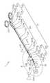
도 1은 본 발명의 제1 실시예에 따른 흉강경 수술용 고정기(1)의 사시도이다.1 is a perspective view of a
흉강경 수술용 고정기(1)는 본체부(10) 및 본체부(10) 단부에서 착탈이 가능한 클램핑부(20)를 포함한다.The fixation device for
흉강경 수술용 고정기(1)의 본체부(10)는 일측에 마련된 한 쌍의 핸들부(110)와, 타측에 마련되어 한 쌍의 핸들부(110)에 의해 단부의 거리가 가변 가능한 한 쌍의 본체 착탈부(130) 및 핸들부(110)와 본체 착탈부(130) 사이에 위치하는 연장부(120)를 포함한다. 핸들부(110)는 사용자가 파지 가능한 파지부(111)와, 파지부(111)와 연결되어 파지부(111)에 의해 제1 연장부(121) 및 제2 연장부(123)의 단부 간의 거리를 변화하도록 돕는 제1 파지 연결부(113a) 및 제2 파지 연결부(113b)를 포함하며, 한 쌍의 파지부(111) 사이에는 제1 가이드 레일(115a)과, 제1 가이드 레일에 레일식으로 맞물리는 제2 가이드 레일(115b)이 형성되어 있는 라킹부(115)가 마련되어 있다.
The
파지부(111)는 사용자의 손가락이 들어갈 정도의 링이 형성되어 있다. 링의 크기와 형태는 제한된 것은 아니며, 원, 타원 등 사용자가 흉강경 수술용 고정기(1)를 쉽게 동작할 수 있도록 도울 수 있을 정도의 크기와 형태로 구성된다.
The
연장부(120)는 제1 연장부(121) 및 제2 연장부(123)로 구성되어 있고, 제1 연장부(121)와 제2 연장부(123)는 서로 밀착되어 고정되어 있으며, 제1 연장부(121)는 제1 파지연결부(113a)에, 제2 연장부(123)는 제2 파지연결부(113b)에 길게 연장되어 있다. 제1 연장부(121) 및 제2 연장부(123)는 신체 내 깊숙이 위치하는 조직에 고정기(1)가 삽입될 수 있도록, 신체 내 삽입 방향으로 길게 연장되어 있다. 또한, 제1 연장부(121)의 말단에는 제1 본체 착탈부(131a), 제2 연장부(123)의 말단에는 제2 본체 착탈부(131b)가 위치한다.The
또한, 본체 착탈부(130)의 각 말단에는 각각 클램프 착탈부(210)가 결합될 수 있도록 돕는 제1 홀(133a) 및 제2 홀(133b)이 형성되어 있다.
A
제1 연장부(121) 및 제2 연장부(123)는 제1 연장부(121) 및 제2 연장부(123) 길이의 수직 방향으로 자른 단면적이 실질적으로 변하지 않는 것을 특징으로 한다. 즉, 연장부(120)의 단면적이 일정하게 유지되며 길게 연장됨으로써, 그 단면적 만큼만의 최소 구멍으로도 흉강경 수술용 고정기(1)가 신체 내부에 삽입될 수 있다. 또한 길게 연장됨으로 인해 신체 내부에 깊숙이 위치해 있는 조직의 위치에 흉강경 수술용 고정기(1)가 삽입될 수 있도록 돕는다.The first extended
이때 연장부(120)의 단면적의 모양은 제1 연장부(121) 및 제2 연장부(123)가 결합된 형태에서 타원 모양이나, 여기에 한정되지 않으며, 신체 내 삽입이 용이하고 수술이 편리한 다양한 모양의 실시예가 존재할 수 있다. 바람직하게는 최소침습술이 가능할 수 있는 모양일 수 있다.
The shape of the cross-sectional area of the
제1 파지 연결부(113a)와 제1 연장부(121), 제2 파지 연결부(113b)와 제2 연장부(123)가 연결되는 구간에는 각각 제1 힌지부(121a) 및 제2 힌지부(123a)가 형성되어 있다. 또한 제1 연장부(121)와 제2 연장부(123)의 타측 말단에도 제3 힌지부(121b) 및 제4 힌지부(123b)가 형성되어 있다. 제1 힌지부(121a) 내지 제4 힌지부(123b)는 핸들부의 움직임에 따라 제2 본체 착탈부(131)를 동작시켜 한 쌍의 클램핑부(20) 간의 거리를 변화시킨다.
The
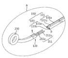
클램핑부(20)는, 조직을 파지하여 고정하는 클램프(230)와, 클램프(230)와 연결되어 본체의 연장부(120)의 단부에 착탈 가능한 클램프 착탈부(210)를 포함한다. 또한, 각 클램프 착탈부(210)의 단부에는 본체부(10)의 본체착탈부(131)과 착탈 가능하도록 돕는 제1 돌출부(211a) 및 제2 돌출부(211b)가 형성되어 있다.The
한 쌍의 클램프(230)들은 도 1에서 도시된 것처럼 본체부(10)의 파지부(111) 평면과 수직으로 세워져있다.
The pair of
도 2는 도 1에서 흉강경 수술용 고정기(1)의 클램핑부(20)가 분리된 A 부분을 확대하여 도시한 것이다.
FIG. 2 is an enlarged view of a portion A of the clamping
클램핑부(20)는 클램프 착탈부(210)의 단부에서 클램프(230)로 올라갈수록 일정 각도로 휘어진 형태로 형성되어있다.The clamping
클램프부(20)가 휘어진 각도는 한정되지 않는다. 다만 신체 내부에서 고정이 필요한 조직을 잘 파지할 수 있도록 다양한 각도로 형성될 수 있다. 다른 실시예로 클램핑부(20)가 휘어지지 않고 직선 형태일 수 있다.
The angle at which the
조직을 파지하는 클램프(230)의 모양은 원형으로 자라나는 암세포 조직을 고정하기 위해 링 형태로 형성된다. 하지만 한정된 것은 아니고, 다른 실시예로 고정하는 신체 조직의 모양에 따라 타원 등 다양한 형태일 수 있다.
The shape of the
본 발명에서의 한 쌍의 클램프(230)는 서로 마주볼 수 있게 배치되지만, 이에 한정된 것은 아니다. 파지하고자 하는 조직을 잘 고정시킬 수 있다면 다양한 배치 및 형태의 다른 실시예가 가능하다.
The pair of
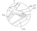
본 발명의 흉강경 수술용 고정기(1)의 클램핑부(20)는 본체부(10)의 연장부(120)와 착탈이 가능한 것을 특징으로 한다. 도 3은 도 2에서 마그네틱이 삽입된 본체 착탈부(130)의 단부와 클램프 착탈부(210)의 단부를 도시한 것이다.The clamping
본체 착탈부(130)의 단부 및 클램프 착탈부(210)의 단부 중 적어도 일부분에 마그네틱이 삽입되어 자성으로 결합되는 것을 특징으로 한다. 이 때 본 발명에서는 본체 착탈부(130)의 단부 표면(p)과 클램핑 착탈부(210)의 단부 표면(q) 모두 마그네틱으로 이루어지지만, 신체 내부에서 본체 착탈부(130)의 단부 및 클램프 착탈부(210)의 단부가 결합이 가능하다면, 이에 한정하지 않고 다양한 실시예가 있을 수 있다.The magnet is inserted into at least a part of the end of the main body
마그네틱이 본체 착탈부(130)의 단부 또는 클램프 착탈부(210)의 단부에만 삽입되어 있을 수 있으며, 이때에는 다른 한 쪽은 마그네틱과 결합 가능한 금속 재질일 수 있다. 또 다른 실시예로 클램프 착탈부(210)의 단부 및 본체 착탈부(130)의 단부 모두에 마그네틱이 삽입되어 있을 수 있다.
The magnet may be inserted only at the end of the main body attaching / detaching
마그네틱의 종류는 바람직하게는 외부로부터 자기 영향에 쉽게 변하지 않는 영구자석일 수 있다. 예를 들어, 네오디움자석, 사마륨코발트자석, 알니코자석, 페라이트자석일 수 있으며 이에 한정되는 것은 아니다. 다만, 신체 내부에서 나타나는 자성의 정도 뿐 아니라, 자석에 의한 신체 내부의 손상 등을 고려하여 선택하여야 한다.The kind of magnet may preferably be a permanent magnet that does not easily change from the outside to magnetic influence. For example, it may be a neodymium magnet, a samarium cobalt magnet, an alnico magnet, or a ferrite magnet, but is not limited thereto. However, it should be selected in consideration of not only the degree of magnetism appearing inside the body but also the damage to the inside of the body by the magnet.
네오디움자석은, 강한 자력에 비해 가격이 저렴하고, 가공성이 뛰어나 원형, 사각형, 링형 등 다양한 형태로 제작이 가능하다는 장점이 있다. 하지만, 수분에 장시간 접촉 시 니켈 도금이 부식될 수 있으므로 이를 고려하여 사용하여야 한다.Neodymium magnets are advantageous in that they can be manufactured in a variety of shapes such as round, square, and ring shapes because they are less expensive than the strong magnetic force and have excellent processability. However, since the nickel plating may corrode during prolonged contact with water, it should be used in consideration of this.
사마륨코발트 자석은 최대 350℃ 까지 높은 온도에서도 자력 감소 없이 사용 가능하나 가격이 고가이므로, 이를 고려해서 사용하여야 한다.Samarium cobalt magnets can be used at high temperatures up to 350 ° C without decreasing magnetic force, but they are expensive and should be used with this in mind.
알니코자석은 온도 특성이 가장 뛰어난 자석으로, 600℃ 이상의 고온에서 사용해도 자력 감소가 거의 없으나, 경도가 높아 가공성이 약간 떨어질 수 있어 주의해야 한다.The AlNiCo magnet has the best temperature characteristics. Even when used at a high temperature of 600 ° C or higher, there is almost no decrease in magnetic force. However, the hardness is high and the workability may be slightly deteriorated.
페라이트 자석은 비교적 온도에 대한 안정성이 높고, 복잡한 형태의 제작이 가능하며, 가격도 저렴해서 일상생활에서 보급형 자석으로 많이 사용된다.
Ferrite magnets have relatively high stability against temperature, can be manufactured in complex shapes, and are inexpensive in price, so they are widely used as popular magnets in everyday life.
또한, 본체 착탈부(130)의 단부와 클램핑 착탈부(210) 단부에 삽입된 마그네틱의 모양이나 크기 및 형태는 제한되지 않는다. 다만, 위에 사용된 마그네틱이 신체 내부에서 자성을 잃지 않고 발휘될 수 있다면, 다양한 실시예가 있을 수 있다.
The shapes, sizes, and shapes of the magnets inserted into the ends of the main body
본체 착탈부(130)의 단부 표면(p)에 형성되어 있는 홀(133)은 클램프 착탈부(210)의 단부 표면(q)에 양각으로 형성된 돌출부(211)가 결합될 수 있도록 음각 형태의 홀(133)로 형성되어 있다. 여기서 양각의 형태와 음각의 형태 및 재질은 한정하지 않으며, 신체 내부에서 클램프 착탈부(210)와 본체 착탈부(130)가 착탈이 쉬운 것을 특징으로 하는 다양한 형태의 실시예가 있을 수 있다. 또한 다른 실시예로, 본체 착탈부(130)의 단부의 표면(p)이 양각, 클램프 착탈부(210)의 단부의 표면(q)이 음각으로 형성될 수 있다.The
이렇게 양각과 음각으로 형성된 본체 착탈부(130)의 단부 표면(p)및 클램프 착탈부(210)의 단부 표면(q)의 형태는, 흉강 안에서 자성으로 결합된 본체부(10)와 클램핑부(20)가 회전하지 않도록 돕는다.
The shape of the end surface p of the main body
도 4는 도 1에서 연장부(120)를 Ⅳ-Ⅳ′방향으로 자른 단면을 도시한 것이고, 도 5의 (a)는 도 1에서 한 쌍의 클램프(230)를 Ⅴ-Ⅴ′방향으로 자른 단면, 도 5의 (b)는 도 1에서 한 개의 클램프(23)를 Ⅴ-Ⅴ′방향으로 자른 단면을 도시한 것이다.FIG. 4 is a cross-sectional view of the
이 때, 연장부(120) 평면의 수직 방향으로 자른 단면적이, 클램프 착탈부(210)와 본체 착탈부(130)의 단부가 결합된 상태에서 클램프(230)를 위 수직 방향과 평행한 방향으로 자른 최대 단면적보다 작은 것을 특징으로 한다. 즉, 종래의 흉강경 수술용 고정기의 경우에는, 흉강경이 출입되는 구멍 이외에 환자의 흉부에 흉강경 수술용 고정기 및 수술도구의 출입을 위한 2개의 큰 구멍이 필요했고, 이 때 흉강경 수술용 고정기가 삽입되는 구멍은 도 5의 (a)에서 도시한 것처럼 클램프 단면적 크기만큼 절개해야만 했다. 하지만 본 발명의 흉강경 수술용 고정기(1)의 경우에는, 클램핑부(20)가 착탈이 가능함으로 인해서, 도 4의 (a)에서 도시된 연장부(120) 단면적 크기만큼의 구멍만 절개하면 되고, 다른 구멍으로 도 5의 (b)에서 도시된 것과 같은 클램프(230) 한 개의 단면적 크기만큼만 절개한다. 따라서 흉강경 수술용 고정기(1)가 환자의 몸에 삽입되기 위해 필요한 단면적이 작아져, 환자 피부의 절개를 최소화할 수 있다.
At this time, the cross-sectional area cut in the vertical direction of the plane of the
조직을 파지하는 클램프(230)의 표면은 실리콘으로 처리된다. 클램프(230)를 실리콘으로 형성하면, 신체 조직이 손상되지 않고 부드럽게 파지할 수 있는 효과가 있다. 기존의 흉강경 수술용 고정기의 클램프 표면은 톱니 형태의 스테인리스 재질로 되어있어, 파지하는 동안 조직을 손상시킬 수 있었고, 이러한 조직이 암세포인 경우 암세포가 흘러나올 수 있는 tumor cell spillage를 일으킬 수 있었다.The surface of the
클램프(23)의 형태는 본 발명의 흉강경 수술용 고정기(1)와 같은 재질로 이루어져 있고, 그 표면 위에 실리콘이 처리되어 있다. 이러한 형태는 한정되지 않으며, 다만 조직을 손상시키지 않으면서도 잘 고정될 수 있도록 다양한 형태의 실시예가 있을 수 있다.The shape of the clamp 23 is made of the same material as the
실리콘의 종류는 조직이 손상되지 않고 파지할 수 있으며, 신체 내에서 안전한 의료용 혹은 인체에 무해한 특성을 가진다면 한정되지 않는다. 예를 들어 경화 시 잔류물이 남지 않고, 무독성인 특성으로 아기 젖병, 장난감 등에 사용되는 LSR (liquid silicone rubber)일 수 있다.
The kind of silicone is not limited as long as it can hold the tissue without damaging it, and is safe in the body or harmless to the human body. For example, it can be a liquid silicone rubber (LSR) that is used for baby bottles, toys, etc., with no residue left after curing and is non-toxic.
또한, 다른 실시예에서는 조직을 손상시키지 않고 파지할 수 있으며, 신체 내에서 안전한, 실리콘이 아닌 다른 재질로 클램프(230)의 표면을 형성할 수 있다.
In another embodiment, the surface of the
클램핑부(20)는 복수의 쌍으로 마련되며, 각각의 쌍은 서로 다른 크기의 클램프(230)를 가진다. 도 6의 (a)~(c)는 클램프(230)의 사이즈 별 클램핑부(20)를 도시한 것이다. 종래 기술의 흉강경 수술용 고정기를 사용할 경우에는, 조직 크기에 맞는 클램프를 포함하는 흉강경 수술용 고정기를 따로 구입해야만 했다. 본 발명은 위에서 설명한 것처럼 클램핑부(20)가 착탈이 가능할 뿐 아니라, 클램프(230) 사이즈별 클램핑부(20)가 하나의 본체부(10)에 결합할 수 있기 때문에, 경제적으로도 부담을 최소화할 수 있다.The clamping
클램핑부(20)에 포함되는 클램프(230)의 크기는 현재 흉강경 폐결절 수술용으로 사용되는 종래의 흉강경 수술용 고정기의 클램프 사이즈인, 45 mm, 35 mm, 25 mm 등으로 형성된다. 그러나 이에 제한된 것은 아니고, 다른 실시예로 파지해야하는 조직의 크기에 따라 다양한 사이즈로 형성될 수 있다.
The size of the
또한, 클램프(230) 사이즈별로 클램핑부(20)는 서로 다른 색상으로 마련된다. 이 경우 사이즈를 직접 숫자로 확인하지 않아도, 색상을 통해 보다 빠르게 클램프(230)의 사이즈 구분이 가능하다.
In addition, the clamping
클램핑부(20)의 색상의 종류나 색이 입혀지는 형태 및 부분은 한정하지 않는다. 다른 실시예로, 클램프 착탈부(210) 전체 표면에 도색되거나, 클램프(230) 혹은 클램프 착탈부(210)의 일부 표면에 도색될 수 있으며, 클램프(230) 사이즈 별로 구분할 수 있다면 어떠한 색상 및 도색의 위치 및 모양이 가능하다.
The type and color of the clamping
이하 도 7 지 도 8을 통하여 흉강경 수술용 고정기의 작동법에 대해 설명한다.Hereinafter, the operation of the fixing device for thoracoscopic surgery will be described with reference to FIG. 7 and FIG.
도 7에서 도시된 것처럼, 흉강경 수술용 고정기를 사용자가 한 쌍의 파지부(111)에 각각 손가락을 넣고 벌리면, 파지 연결부(113)와 연결된 연장부(120)의 단부간의 거리가 변화하고, 여기에 연결된 클램핑부(20)도 벌어져 조직을 고정할 수 있게 된다. 이 때, 제1 가이드 레일(115a)과 제2 가이드 레일(115b)은, 한 쌍의 클램핑부(20)가 조직을 파지하고 고정시킬 때 조직에 과도한 힘이 가해지는 것을 저지하고, 조직에 가해지는 힘을 유지시킬 수 있는 역할을 한다.7, when the user inserts and spreads a finger on each of the pair of
도 8은 도 7에서 도시한 흉강경 수술용 고정기(1)의 라킹부(115)의 B부분을 확대하여 도시한 것이다.FIG. 8 is an enlarged view of the portion B of the locking
파지되는 조직의 크기나 두께에 따라 제1 가이드 레일(115a)과 제2 가이드 레일(115b)을 상호간 한 칸씩 이동시켜 고정함으로써, 조직에 가해지는 힘을 조절하여 유지될 수 있게 한다.
The
여기서, 제1 파지 연결부(113a)는 제1 연장부(121)와 연결되어 있고, 제2 파지 연결부(113b)는 제2 연장부(123)와 연결되어 있다. 사용자가 파지부(111)를 벌리면, 제2 파지 연결부(113b) 및 제2 연장부(123)를 축으로 해서, 제1 파지 연결부(113a)의 움직임에 따라, 제2 연장부(123)의 단부에 연결된 제2 본체 착탈부(131b) 및 여기에 연결된 제2 돌출부(211b)가 제1 본체 착탈부(131a)에 연결된 제1 돌출부(211a)의 반대 방향으로 움직여 벌어진다. 이러한 흉강경 수술용 고정기(1)의 작동 원리는 상기 설명에 제한되는 것은 아니고, 다양한 실시예가 있을 수 있다.
The
이하, 도 9를 통해 본 발명의 흉강경 수술용 고정기(1)를 이용한 폐결절 수술 방법을 설명한다.Hereinafter, a method for pulmonary nodule surgery using the fixator for
우선, 수술 부위의 부근에 흉강경 카메라가 삽입될 1개의 4-5 cm의 a구멍과, 제거된 폐 조직을 빼낼 수 있는 1개의 1 cm의 b구멍, 그리고 흉강경 수술용 고정기가 들어갈 수 있는 최소한의 크기의 c구멍이 형성되도록 절개한다.First, a 4-5 cm a hole in the vicinity of the surgical site to insert a thoracoscopic camera, a 1 cm b hole to remove the removed lung tissue, and a minimal And a c-hole of size is formed.
a구멍에 흉강경을 삽입하고, b구멍과 c구멍에 이중관 기관 내 튜브 (double lumen endotracheal tube)를 삽입하여, 폐를 collapse 시켜 수술 공간을 확보한다.a Insert the thoracoscopic hole into the hole and inserting a double lumen endotracheal tube into the b hole and the c hole to collapse the lung to secure the surgical space.
파지하고자 하는 조직의 크기에 맞는 클램프(230)를 포함하는 클램핑부(20)를 선택하고, 클램핑부(20)는 b구멍에, 본체부(10)는 c구멍에 삽입하여 흉강 안에서 클램핑부(20)와 본체부(10)를 결합한다. 폐를 collapse 시킨 흉강 안의 공간이 넓어 작업 공간 확보가 용이하므로 클램핑부(20)와 본체부(10)를 쉽게 결합할 수 있다.
The clamping
이렇게 결합된 흉강경 수술용 고정기(1)의 연장부(120)를, 파지하고자 하는 폐결절 부위까지 삽입하고, 상기 설명한 동작 방법에 의해 파지 및 고정한다.The
수술 완료 후, 흉강 안에서 클램핑부(20)와 본체부(10)를 분리하고 각각의 삽입했던 구멍으로 빼낸다.
After the operation is completed, the clamping
도 10은 본 발명의 제2 실시예에 따른 흉강경 수술용 고정기(1)의 클램핑부(20)를 도시한 것이다. 나선 스크류 방식으로 착탈할 수 있는 본체 착탈부(131)의 단부와 클램프 착탈부(210)의 단부를 보여준다. 본체 착탈부(131)의 단부는 수나사(bolt)로 형성되어 있고, 클램프 착탈부(210)의 단부는 암나사(nut)로 형성되어, 흉강 안에서 조립하여 사용할 수 있다.10 shows a clamping
수나사로 형성된 본체 착탈부(131)의 단부의 제1 수나사부(135a) 및 제2 수나사부(135b), 암나사로 형성된 클램프 착탈부(210)의 제1 암나사부(213a) 및 제2 암나사부(213b)의 길이와 크기는 한정되지 않는다. 다만, 흉강 안에서 수나사부(135)와 암나사부(213)가 잘 맞물리며, 쉽게 탈착이 가능하도록 형성되어야 한다. 다른 실시예로, 본체 착탈부(131)의 단부가 암나사(nut), 클램프 착탈부(210)의 단부가 수나사(bolt)로 형성될 수 있다.
The first
본체 착탈부(131)의 단부와 클램프 착탈부(210)의 단부의 착탈 방식은 위에서 제시한 마그네틱 혹은 나선 스크류 방식에 한정된 것은 아니며, 신체 내에서 안전하게 착탈할 수 있다면, 다른 실시예로 어떠한 방식으로도 착탈 가능하며, 그 방식에 따라 본체 착탈부(131)의 단부와 클램프 착탈부(210)의 형태도 다양하게 제작 가능하다.
The attachment / detachment of the end of the main body attachment /
도 11은 본 발명의 제3 실시예에 따른 흉강경 수술용 고정기(1)의 사시도이다. 도 1의 제1 실시예와 모양과 형태가 같으나, 작동 원리가 다른 실시예이다. 사용자가 파지부에 손가락을 넣고, 도 11의 d 방향으로 벌리면 여기에 연결된 제1 파지연결부(113a)가 벌어지게 되고, 이때 제1 연장부(121)는 제1 파지 연결부(113a)의 단부에 의해 슬라이드 형식으로 밀려 도 11의 e 방향으로 밀리게 된다. 밀린 제1 연방부(121)는 여기에 슬라이드 형식으로 연결된 제2 본체 착탈부(131b)를 벌어지게 하고, 여기에 부착되어 있는 클램프 착탈부(210)를 도 11의 f 방향으로 벌어지게 한다.11 is a perspective view of a
이러한 흉강경 수술용 고정기(1)의 작동 원리는 독일 SCANLAN 회사에서 제조하는 node grasping clamps (제품번호: 9009-23)와 동일할 수 있다. 하지만 여기에 제한되는 것은 아니고, 다양한 작동 원리의 실시예가 있을 수 있다.
The operation principle of the screw fixator for thoracoscopic surgery (1) may be the same as that of node grasping clamps (product number: 9009-23) manufactured by SCANLAN, Germany. However, it is not limited thereto, and there may be embodiments of various operating principles.
종래의 흉강경 수술용 고정기는 클램핑부가 본체부에 착탈이 불가능했기 때문에, 신체에 삽입하려면, 삽입하고자하는 클램프의 단면적만큼 피부를 절개해야만했다. 하지만 본 발명에서 흉강경 수술용 고정기(1)가 삽입될 구멍의 크기는, 그 보다 작은 연장부(120)의 단면적 크기만으로도 가능하기 때문에, 피부 절개를 최소화할 수 있다. 여기서 피부를 뚫고 들어가는 부분인 연장부(120)의 shaft를, 기존 흉강경 수술에서 가장 작은 port인 5mm로 형성할 수 있다면, 최소침습수술이 가능하다.In the conventional fixation device for a thoracoscopic surgery, since the clamping portion can not be attached to or detached from the body portion, the skin has to be cut by the cross-sectional area of the clamp to be inserted into the body. However, in the present invention, the size of the hole into which the fixator for
절개 부위가 최소화될 수 있다는 것은, 상처의 크기가 작아지고 치유속도가 빨라질 뿐 아니라, 환자의 만족감도 높여줄 수 있는 효과가 있다. 또한, 클램프(230) 사이즈별 클램핑부(20)만 구입할 수 있으므로 경제적으로도 부담을 줄일 수 있으며, 클램프(230) 사이즈별로 다른 색으로 형성되어 있다면 색 만으로도 쉽게 클램프(230)의 크기를 구분할 수 있다.The fact that the incision can be minimized has the effect of not only increasing the size of the wound, speeding up the healing, but also increasing the patient's satisfaction. In addition, since only the clamping
그리고 실리콘 재질로 형성되어 있는 클램프(230)는, 기존 톱니형태의 스테인리스 재질보다 부드럽게 형성될 수 있어서, 조직의 손상을 방지할 수 있는 효과가 있다.
Further, the
전술한 실시예들은 본 발명을 설명하기 위한 예시로서, 본 발명이 이에 한정되는 것은 아니다. 본 발명이 속하는 기술 분야에서 통상의 지식을 가진 자라면 이로부터 다양하게 변형하여 본 발명을 실시하는 것이 가능할 것이므로, 본 발명의 기술적 보호 범위는 모든 변형 및 수정도 본 발명의 범위에 속하는 것으로 간주되어야 할 것이다.
The above-described embodiments are illustrative of the present invention, and the present invention is not limited thereto. It will be understood by those skilled in the art that various changes in form and details may be made therein without departing from the spirit and scope of the present invention as defined by the appended claims and their equivalents. something to do.
Claims (11)
Translated fromKorean일측에 마련된 한 쌍의 핸들부;와
타측에 마련되어 상기 한 쌍의 핸들부에 의해 단부의 거리가 가변 가능한 한 쌍의 본체 착탈부;및
상기 핸들부와 상기 본체 착탈부 사이에 위치하는 연장부;
를 포함하는 본체부;와
상기 본체 착탈부에 착탈 가능하게 결합되는 클램프 착탈부;및
상기 핸들부의 작동에 연동하여 조직을 파지하는 적어도 한 쌍의 클램프;
를 포함하는 클램핑부;
를 포함하는 고정기.In a fixator for grasping tissue to be removed in thoracoscopic surgery,
A pair of handle portions provided on one side;
A pair of main body attaching / detaching portions provided on the other side and capable of varying the distance of the end portions by the pair of handle portions;
An extension disposed between the handle portion and the main body detachable portion;
And
A clamp detachable portion detachably coupled to the main body detachable portion;
At least a pair of clamps for gripping the tissue in cooperation with the operation of the handle portion;
A clamping part including a clamping part;
≪ / RTI >
상기 연장부는 신체 내 삽입 방향을 따라 길게 연장되는 것을 특징으로 하며, 길이의 수직방향을 따라 자른 단면적이 실질적으로 변하지 않는 특징을 포함하는 고정기.The method according to claim 1,
Wherein the extension is elongated along an insertion direction in the body, and the cross-sectional area along the vertical direction of the length is substantially unchanged.
상기 한 쌍의 클램핑부 표면의 적어도 일부는 실리콘으로 처리되어 있는 것을 특징으로 하는 고정기.The method according to claim 1,
Wherein at least a part of the surfaces of the pair of clamping parts is treated with silicon.
상기 한 쌍의 본체 착탈부와 와 상기 한 쌍의 클램프 착탈부는 자성에 의해 착탈 가능하게 마련되는 것을 특징으로 하는 고정기.The method according to claim 1,
Wherein the pair of main body attaching / detaching portions and the pair of clamp attaching / detaching portions are detachably provided by magnetism.
상기 한 쌍의 본체 착탈부의 단부와 상기 한 쌍의 클램프 착탈부의 단부 중 어느 하나는 양각, 다른 하나는 음각의 형태로 결합되어 착탈 가능하게 마련되는 것을 특징으로 하는 고정기.5. The method of claim 4,
Wherein one of the end portions of the pair of main body attaching / detaching portions and the end portion of the pair of clamp attaching / detaching portions is engaged with an embossed shape and the other is engageable / detachable.
상기 한 쌍의 본체 착탈부와 상기 한 쌍의 클램프 착탈부는 나선 스크류 방식에 의해 착탈이 가능하게 마련되는 것을 특징으로 하는 고정기.The method according to claim 1,
Wherein the pair of main body attaching / detaching portions and the pair of clamp attaching / detaching portions are attachable / detachable by a spiral screw method.
상기 클램핑부는 복수의 쌍으로 마련되며,
각각의 쌍은 서로 다른 크기의 클램프를 가지는 것을 특징으로 하는 고정기.The method according to claim 1,
Wherein the clamping portion is provided in a plurality of pairs,
Each pair having a clamp of a different size.
상기 클램핑부의 적어도 일부분은 각 크기별로 서로 다른 색으로 마련되는 것을 특징으로 하는 고정기.8. The method of claim 7,
Wherein at least some of the clamping portions are provided in different colors for respective sizes.
상기 클램프는 링 타입인 것을 특징으로 하는 고정기.The method according to claim 1,
Wherein the clamp is a ring type.
상기 클램프는 서로 마주보는 것을 특징으로 하는 고정기.The method according to claim 1,
Wherein the clamps are opposed to each other.
상기 연장부 평면의 수직 방향으로 자른 단면적이, 상기 클램핑부와 상기 연장부의 단부가 결합된 상태에서 상기 클램프를 상기 수직 방향과 평행한 방향으로 자른 최대 단면적보다 작은 것을 특징으로 하는 고정기.
The method according to claim 1,
Sectional area in a direction perpendicular to the plane of the extended portion is smaller than a maximum sectional area of the clamp cut in a direction parallel to the vertical direction in a state where the clamping portion and the end portion of the extended portion are engaged.
Priority Applications (2)
| Application Number | Priority Date | Filing Date | Title |
|---|---|---|---|
| KR1020150062666AKR20160130638A (en) | 2015-05-04 | 2015-05-04 | Fixator for thoracoscopic surgery |
| PCT/KR2016/004662WO2016178504A1 (en) | 2015-05-04 | 2016-05-03 | Clamping device for thoracoscopic surgery |
Applications Claiming Priority (1)
| Application Number | Priority Date | Filing Date | Title |
|---|---|---|---|
| KR1020150062666AKR20160130638A (en) | 2015-05-04 | 2015-05-04 | Fixator for thoracoscopic surgery |
Publications (1)
| Publication Number | Publication Date |
|---|---|
| KR20160130638Atrue KR20160130638A (en) | 2016-11-14 |
Family
ID=57218553
Family Applications (1)
| Application Number | Title | Priority Date | Filing Date |
|---|---|---|---|
| KR1020150062666ACeasedKR20160130638A (en) | 2015-05-04 | 2015-05-04 | Fixator for thoracoscopic surgery |
Country Status (2)
| Country | Link |
|---|---|
| KR (1) | KR20160130638A (en) |
| WO (1) | WO2016178504A1 (en) |
Cited By (1)
| Publication number | Priority date | Publication date | Assignee | Title |
|---|---|---|---|---|
| KR20200122840A (en)* | 2019-04-19 | 2020-10-28 | 중앙대학교 산학협력단 | Linear stapler for laparoscopic surgery |
Citations (1)
| Publication number | Priority date | Publication date | Assignee | Title |
|---|---|---|---|---|
| KR20130027966A (en) | 2011-09-08 | 2013-03-18 | 주식회사 모바수 | Instrument for minimally invasive surgery having attachable/detachable end effector |
Family Cites Families (5)
| Publication number | Priority date | Publication date | Assignee | Title |
|---|---|---|---|---|
| US6293954B1 (en)* | 1999-06-21 | 2001-09-25 | Novare Surgical Systems, Inc. | Surgical clamp with replaceable clamp members |
| KR100592944B1 (en)* | 2005-03-22 | 2006-06-26 | 문현준 | Multiple annular tubular separator |
| JP5388095B2 (en)* | 2008-09-30 | 2014-01-15 | 公益財団法人北九州産業学術推進機構 | Pinching device |
| US8133254B2 (en)* | 2009-09-18 | 2012-03-13 | Tyco Healthcare Group Lp | In vivo attachable and detachable end effector assembly and laparoscopic surgical instrument and methods therefor |
| JP5878010B2 (en)* | 2011-12-16 | 2016-03-08 | 静岡県 | Grasping forceps |
- 2015
- 2015-05-04KRKR1020150062666Apatent/KR20160130638A/ennot_activeCeased
- 2016
- 2016-05-03WOPCT/KR2016/004662patent/WO2016178504A1/ennot_activeCeased
Patent Citations (1)
| Publication number | Priority date | Publication date | Assignee | Title |
|---|---|---|---|---|
| KR20130027966A (en) | 2011-09-08 | 2013-03-18 | 주식회사 모바수 | Instrument for minimally invasive surgery having attachable/detachable end effector |
Cited By (1)
| Publication number | Priority date | Publication date | Assignee | Title |
|---|---|---|---|---|
| KR20200122840A (en)* | 2019-04-19 | 2020-10-28 | 중앙대학교 산학협력단 | Linear stapler for laparoscopic surgery |
Also Published As
| Publication number | Publication date |
|---|---|
| WO2016178504A1 (en) | 2016-11-10 |
Similar Documents
| Publication | Publication Date | Title |
|---|---|---|
| KR102552209B1 (en) | vaginal speculum | |
| US20130345762A1 (en) | Soft tissue bone reduction forceps | |
| CA1062108A (en) | Surgical retractor | |
| CN203885568U (en) | Bending forceps special for bone plate | |
| KR20160130638A (en) | Fixator for thoracoscopic surgery | |
| CN103610502B (en) | Instrument bag for miniature incision surgery of department of cardiac surgery | |
| CN207400777U (en) | A kind of Perineal stitching auxiliary forceps and suture operation instrument | |
| KR102032510B1 (en) | Medical Trcar | |
| CN216417241U (en) | Clip-on Automatic Tissue Hanger | |
| CN206026396U (en) | Haplopore chest separation plier for laparoscopic surgery | |
| CN203776989U (en) | Gripping clamp used for minimal invasive thoracoscope operation | |
| CN212490061U (en) | Separation forceps for vertebral artery surgery | |
| CN214073485U (en) | Separable tissue forceps | |
| CN102743200A (en) | Assembly type skin retractor | |
| CN208096792U (en) | Operation on Esophageal Cancer purse-string forceps under a kind of thoracoscope | |
| CN203634296U (en) | Operation instrument set for cardiac surgery miniature incision | |
| CN221844894U (en) | Spoon-shaped separating forceps | |
| EP3104929B1 (en) | Insertion tool | |
| CN201798791U (en) | Combined type thoracolumbar spine clamping tongs | |
| RU107037U1 (en) | PERICOSTAL LIGATURE CONDUCTOR | |
| CN213722216U (en) | Convenient hemostatic forceps for gynecologic operation who adjusts | |
| CN214632264U (en) | Sponge forceps for endoscopic surgery | |
| CN211156066U (en) | Hemostatic forceps for obstetrics and gynecology department | |
| CN212140565U (en) | Internal fixator for dislocation of ribs and transverse process and rib fracture under endoscope | |
| CN2479920Y (en) | Fixator for thyroidectomy |
Legal Events
| Date | Code | Title | Description |
|---|---|---|---|
| A201 | Request for examination | ||
| PA0109 | Patent application | Patent event code:PA01091R01D Comment text:Patent Application Patent event date:20150504 | |
| PA0201 | Request for examination | ||
| E902 | Notification of reason for refusal | ||
| PE0902 | Notice of grounds for rejection | Comment text:Notification of reason for refusal Patent event date:20160803 Patent event code:PE09021S01D | |
| AMND | Amendment | ||
| PG1501 | Laying open of application | ||
| E601 | Decision to refuse application | ||
| PE0601 | Decision on rejection of patent | Patent event date:20170201 Comment text:Decision to Refuse Application Patent event code:PE06012S01D Patent event date:20160803 Comment text:Notification of reason for refusal Patent event code:PE06011S01I | |
| AMND | Amendment | ||
| PX0901 | Re-examination | Patent event code:PX09011S01I Patent event date:20170201 Comment text:Decision to Refuse Application Patent event code:PX09012R01I Patent event date:20160930 Comment text:Amendment to Specification, etc. | |
| E902 | Notification of reason for refusal | ||
| PE0902 | Notice of grounds for rejection | Comment text:Notification of reason for refusal Patent event date:20170403 Patent event code:PE09021S01D | |
| PX0601 | Decision of rejection after re-examination | Comment text:Decision to Refuse Application Patent event code:PX06014S01D Patent event date:20171103 Comment text:Notification of reason for refusal Patent event code:PX06013S01I Patent event date:20170403 Comment text:Amendment to Specification, etc. Patent event code:PX06012R01I Patent event date:20170322 Comment text:Decision to Refuse Application Patent event code:PX06011S01I Patent event date:20170201 Comment text:Amendment to Specification, etc. Patent event code:PX06012R01I Patent event date:20160930 Comment text:Notification of reason for refusal Patent event code:PX06013S01I Patent event date:20160803 |