KR20160129874A - Integration of touch screen and fingerprint sensor assembly - Google Patents
Integration of touch screen and fingerprint sensor assemblyDownload PDFInfo
- Publication number
- KR20160129874A KR20160129874AKR1020167027198AKR20167027198AKR20160129874AKR 20160129874 AKR20160129874 AKR 20160129874AKR 1020167027198 AKR1020167027198 AKR 1020167027198AKR 20167027198 AKR20167027198 AKR 20167027198AKR 20160129874 AKR20160129874 AKR 20160129874A
- Authority
- KR
- South Korea
- Prior art keywords
- touch screen
- glass cover
- tempered glass
- layer
- fingerprint
- Prior art date
- Legal status (The legal status is an assumption and is not a legal conclusion. Google has not performed a legal analysis and makes no representation as to the accuracy of the status listed.)
- Ceased
Links
Images


Classifications
- G—PHYSICS
- G06—COMPUTING OR CALCULATING; COUNTING
- G06V—IMAGE OR VIDEO RECOGNITION OR UNDERSTANDING
- G06V40/00—Recognition of biometric, human-related or animal-related patterns in image or video data
- G06V40/10—Human or animal bodies, e.g. vehicle occupants or pedestrians; Body parts, e.g. hands
- G06V40/12—Fingerprints or palmprints
- G06V40/13—Sensors therefor
- G06V40/1312—Sensors therefor direct reading, e.g. contactless acquisition
- G06K9/00033—
- G—PHYSICS
- G06—COMPUTING OR CALCULATING; COUNTING
- G06F—ELECTRIC DIGITAL DATA PROCESSING
- G06F1/00—Details not covered by groups G06F3/00 - G06F13/00 and G06F21/00
- G06F1/16—Constructional details or arrangements
- G06F1/1613—Constructional details or arrangements for portable computers
- G06F1/1626—Constructional details or arrangements for portable computers with a single-body enclosure integrating a flat display, e.g. Personal Digital Assistants [PDAs]
- G—PHYSICS
- G06—COMPUTING OR CALCULATING; COUNTING
- G06F—ELECTRIC DIGITAL DATA PROCESSING
- G06F1/00—Details not covered by groups G06F3/00 - G06F13/00 and G06F21/00
- G06F1/16—Constructional details or arrangements
- G06F1/1613—Constructional details or arrangements for portable computers
- G06F1/1633—Constructional details or arrangements of portable computers not specific to the type of enclosures covered by groups G06F1/1615 - G06F1/1626
- G06F1/1637—Details related to the display arrangement, including those related to the mounting of the display in the housing
- G06F1/1643—Details related to the display arrangement, including those related to the mounting of the display in the housing the display being associated to a digitizer, e.g. laptops that can be used as penpads
- G—PHYSICS
- G06—COMPUTING OR CALCULATING; COUNTING
- G06F—ELECTRIC DIGITAL DATA PROCESSING
- G06F1/00—Details not covered by groups G06F3/00 - G06F13/00 and G06F21/00
- G06F1/16—Constructional details or arrangements
- G06F1/1613—Constructional details or arrangements for portable computers
- G06F1/1633—Constructional details or arrangements of portable computers not specific to the type of enclosures covered by groups G06F1/1615 - G06F1/1626
- G06F1/1684—Constructional details or arrangements related to integrated I/O peripherals not covered by groups G06F1/1635 - G06F1/1675
- G06K9/0002—
- G06K9/00053—
- G06K9/00885—
- G—PHYSICS
- G06—COMPUTING OR CALCULATING; COUNTING
- G06V—IMAGE OR VIDEO RECOGNITION OR UNDERSTANDING
- G06V40/00—Recognition of biometric, human-related or animal-related patterns in image or video data
- G06V40/10—Human or animal bodies, e.g. vehicle occupants or pedestrians; Body parts, e.g. hands
- G06V40/12—Fingerprints or palmprints
- G06V40/13—Sensors therefor
- G06V40/1306—Sensors therefor non-optical, e.g. ultrasonic or capacitive sensing
- G—PHYSICS
- G06—COMPUTING OR CALCULATING; COUNTING
- G06V—IMAGE OR VIDEO RECOGNITION OR UNDERSTANDING
- G06V40/00—Recognition of biometric, human-related or animal-related patterns in image or video data
- G06V40/10—Human or animal bodies, e.g. vehicle occupants or pedestrians; Body parts, e.g. hands
- G06V40/12—Fingerprints or palmprints
- G06V40/13—Sensors therefor
- G06V40/1329—Protecting the fingerprint sensor against damage caused by the finger
- G—PHYSICS
- G06—COMPUTING OR CALCULATING; COUNTING
- G06V—IMAGE OR VIDEO RECOGNITION OR UNDERSTANDING
- G06V40/00—Recognition of biometric, human-related or animal-related patterns in image or video data
- G06V40/10—Human or animal bodies, e.g. vehicle occupants or pedestrians; Body parts, e.g. hands
- G06V40/15—Biometric patterns based on physiological signals, e.g. heartbeat, blood flow
- G06K2009/00939—
Landscapes
- Engineering & Computer Science (AREA)
- Theoretical Computer Science (AREA)
- Human Computer Interaction (AREA)
- Physics & Mathematics (AREA)
- General Physics & Mathematics (AREA)
- Computer Hardware Design (AREA)
- General Engineering & Computer Science (AREA)
- Multimedia (AREA)
- Life Sciences & Earth Sciences (AREA)
- Biophysics (AREA)
- Cardiology (AREA)
- General Health & Medical Sciences (AREA)
- Heart & Thoracic Surgery (AREA)
- Physiology (AREA)
- Health & Medical Sciences (AREA)
- Image Input (AREA)
- Measurement Of The Respiration, Hearing Ability, Form, And Blood Characteristics Of Living Organisms (AREA)
Abstract
Translated fromKorean
Description
Translated fromKorean본원 발명은 출원번호가 62/021,632이고 출원일자가 2014년 07월 07일인 미국 특허 가출원에 기반하여 제출하였고 상기 특허 출원의 우선권을 주장하는 바, 상기 특허 출원의 모든 내용은 본원 발명에 원용된다.The present invention is based on US Patent Application No. 62 / 021,632 filed on Jul. 07, 2014, and claims priority to the above patent application, which is incorporated herein by reference in its entirety.
본 발명은 터치 스크린 기기 및 기술에 관한 것이다.The present invention relates to touch screen devices and techniques.
노트북, 태블릿, 스마트폰 및 게임 시스템과 같은 모바일 컴퓨팅 기기를 사용하는 사용자는 일반적으로 그들의 장치에서 개인 데이터를 보호하기 위한 사용자 인증을 이용하여, 무단 엑세스를 방지할 수 있다. 날따라 증가되는 사용자의 보안 및 개인 정보 보호 요구를 만족시키기 위해, 기존의 패스워드 인증 이외에, 전자 기기의 사용자 인증은 하나 또는 복수개의 형태의 생체 인식 장치로 구현할 수 있다. 생체 인식의 보편적인 형태는 사람의 지문 모드이다. 지문 센서는 전자 기기에 집적되어 사용자의 지문 모드를 판독하는 것으로서 상기 기기는 인증할 사용자의 지문을 식별하는 모드를 통해, 장치 소유자한테만 잠금 해제를 허락하도록 한다. 특히, 지문 센서는 터치 스크린을 구비한 스마트폰에 집적시킬 수 있으며, 이로써 스크린이 잠겨진 스마트폰을 손가락으로 원버튼을 간단하게 터치하는 것을 통해 잠금 해제할 수 있는 바, 패스워드를 입력할 필요가 없다.Users using mobile computing devices such as laptops, tablets, smart phones and gaming systems can typically use user authentication to protect their personal data on their devices to prevent unauthorized access. In addition to conventional password authentication, the user authentication of the electronic device can be implemented by one or a plurality of types of biometric devices in order to satisfy security and personal information protection requirements of the user, which are increased along the day. A universal form of biometrics is the human fingerprint mode. The fingerprint sensor is integrated in the electronic device to read the fingerprint mode of the user, and the device allows the device owner to unlock only through the mode of identifying the fingerprint of the user to authenticate. In particular, the fingerprint sensor can be integrated into a smartphone equipped with a touch screen, thereby unlocking the smartphone with the screen by simply touching the one button with a finger, without having to input a password .
본 발명은 지문 검출 모듈과 터치 스크린을 집적한 구조의 기기와 기술을 공개하였고, 터치 스크린과 지문 검출 모듈을 물리적으로 모바일 기기 또는 휴대 가능한 기기와 같은 상이한 기기 어셈블리에 집적시킨 기기, 시스템 및 기술을 포함한다. 상기 집적 터치 스크린과 지문 센서 어셈블리는 함께 접합되어 터치 스크린에 완전한 기계적 강도를 제공하는 적어도 두 개의 유리층을 포함한다. 상층 유리층은 강화/강화 유리 커버이고, 상기 유리층을 통과하고 지문 검출 모듈을 장착하기 위한 개구를 포함하지 않는다. 하층 유리층은 유리 지지층이고, 강화 유리 커버의 하방에 위치하며, 별도의 기계적 강도를 제공한다. 또한, 상기 유리 지지층은 상기 유리 지지층의 후미부에 근접한 개구를 포함한다. 상기 집적 터치 스크린과 지문 센서 어셈블리는 상기 유리 지지층의 개구 내에 위치한 지문 검출 모듈을 더 포함하고, 직접적으로 강화 유리 커버의 하방에 있다. 상기 집적 터치 스크린과 지문 센서 어셈블리는 강화 유리 커버의 표면에 형성된 지문 센서 마크에 더 포함되고, 상기 지문 검출 모듈의 상방에 위치하며, 지문 검출 모듈의 위치를 지시한다. 언급한 스크린과 지문 센서 어셈블리는 지문 센서에서의 강화 유리 커버를 통과하는 큰 홀을 제거하였기에 기기의 외관과 지문 센서의 성능 및 신뢰성, 공간 절약을 크게 상승시켰고, 또한 제조 원가를 대폭 절감하였다.The present invention discloses a device and a technology in which a fingerprint detection module and a touch screen are integrated, and a device, a system and a technology in which a touch screen and a fingerprint detection module are physically integrated in different device assemblies such as a mobile device or a portable device . The integrated touch screen and the fingerprint sensor assembly include at least two glass layers joined together to provide the complete mechanical strength to the touch screen. The upper glass layer is a reinforced / tempered glass cover and does not include openings for passing through the glass layer and for mounting the fingerprint detection module. The lower glass layer is a glass support layer and is located below the tempered glass cover and provides a separate mechanical strength. Further, the glass support layer includes an opening close to the rear portion of the glass support layer. The integrated touch screen and the fingerprint sensor assembly further include a fingerprint detection module located within the opening of the glass support layer and directly below the tempered glass cover. The integrated touch screen and the fingerprint sensor assembly are further included in a fingerprint sensor mark formed on the surface of the tempered glass cover and are positioned above the fingerprint detection module and indicate the position of the fingerprint detection module. The aforementioned screen and fingerprint sensor assembly greatly removed the large holes passing through the tempered glass cover of the fingerprint sensor, thus greatly improving the performance and reliability of the device and the fingerprint sensor, saving space and greatly reducing the manufacturing cost.
한편으로는, 터치 스크린 패널과 터치 스크린 패널 외측 및 터치 스크린 패널에 근접한 지문 센서; 공간적으로 연속된 유리 표면을 구비하여 상기 터치 스크린 패널과 터치 스크린 패널 외측 및 터치 스크린 패널에 근접한 상기 지문 센서 모듈을 완전히 커버하는 상기 터치 스크린과 지문 센서의 어셈블리의 상층의 강화 유리 커버; 강화 유리 커버의 하방에 위치하고 개구를 포함하는 상기 유리 지지층을 포함하는 터치 스크린과 지문 센서의 어셈블리를 제공한다. 상기 개구는 상기 유리 지지층을 통과한다. 상기 강화 유리 커버와 상기 유리 지지층은 함께 접합되어 상기 터치 스크린에 필요한 기계적 강도를 제공한다. 상기 지문 센서 모듈은 상기 유리 지지층의 개구 내에 위치하고, 상기 강화 유리 커버의 하방에서 강화 유리 커버를 통해 손가락과 같은 접촉된 물체를 센싱한다.On the one hand, fingerprint sensors proximate the touchscreen panel and the touchscreen panel and proximate the touchscreen panel; A toughened glass cover having a spatially continuous glass surface on the upper layer of the touch screen and fingerprint sensor assembly that completely covers the fingerprint sensor module outside the touch screen panel and the touch screen panel and proximate to the touch screen panel; An assembly of a touch screen and a fingerprint sensor, comprising a glass support layer positioned below the tempered glass cover and including an opening. The opening passes through the glass support layer. The tempered glass cover and the glass support layer are bonded together to provide the mechanical strength required for the touch screen. The fingerprint sensor module is located within the opening of the glass support layer and senses a contact object such as a finger through the tempered glass cover below the tempered glass cover.
다른 한편으로는, 모바일 기기의 터치 스크린과 지문 센서의 어셈블리는 상기 터치 스크린과 지문 센서의 어셈블리의 상층에 위치한 강화 유리 커버를 포함한다. 상기 터치 스크린과 지문 센서의 어셈블리는 상기 강화 유리 커버의 하방에 위치하고 개구를 가진 유리 지지층을 더 포함한다. 상기 강화 유리 커버와 상기 유리 지지층은 함께 접합되어, 상기 터치 스크린과 지문 센서의 어셈블리의 기계적 강도를 지원하도록 제공한다. 상기 터치 스크린과 지문 센서의 어셈블리는 상기 유리 지지층의 개구 내에 위치한 지문 검출 모듈을 더 포함하고, 상기 강화 유리 커버의 하방에 위치한다.On the other hand, the touch screen of the mobile device and the assembly of the fingerprint sensor include a tempered glass cover located on the upper layer of the touch screen and the fingerprint sensor assembly. The assembly of the touch screen and the fingerprint sensor further includes a glass support layer positioned below the tempered glass cover and having an opening. The tempered glass cover and the glass support layer are joined together to provide mechanical strength of the touch screen and fingerprint sensor assembly. The assembly of the touch screen and the fingerprint sensor further includes a fingerprint detection module located within the opening of the glass support layer and is located below the tempered glass cover.
일부를 실현함에 있어서, 상기 터치 스크린과 지문 센서의 어셈블리는 강화 유리 커버의 표면에 형성되고, 상기 지문 검출 모듈의 상방에 위치하여, 지문 검출 모듈의 위치를 지시하는 지문 센서 마크를 더 포함한다.In some embodiments, the touch screen and the fingerprint sensor assembly are formed on the surface of the tempered glass cover, and further include a fingerprint sensor mark positioned above the fingerprint detection module and indicating the position of the fingerprint detection module.
다른 한편으로는, 지문 검출 수단을 집적시킨 터치 스크린 전자 기기는 프레임을 포함하고, 상기 터치 스크린과 지문 센서의 어셈블리는 프레임에 의해 둘려싸여 보호되는다. 상기 터치 스크린과 지문 센서의 어셈블리는, 터치 스크린과 지문 센서의 어셈블리의 상층에 위치하고 물체와의 접촉을 수신하기 위한 강화 유리 커버; 상기 유리 지지층을 통과하는 개구를 포함하는 강화 유리 커버의 하면의 유리 지지층; 상기 유리 지지층의 개구 내에 위치하고 상기 강화 유리 커버의 하방에 위치하는 지문 검출 모듈을 포함하고, 여기서 상기 강화 유리 커버와 상기 유리 지지층은 하나로 접착되어, 상기 터치 스크린 어셈블리의 기계적 강도를 지원하도록 제공되며, 상기 터치 스크린 전자 기기는 상기 터치 스크린 어셈블리와 상기 프레임의 후면 커버 사이의 주 회로 기판을 더 포함한다.On the other hand, the touch screen electronic device incorporating the fingerprint detection means includes a frame, and the assembly of the touch screen and the fingerprint sensor is surrounded and protected by the frame. The assembly of the touch screen and the fingerprint sensor includes: a tempered glass cover positioned on an upper layer of the touch screen and the fingerprint sensor assembly and receiving contact with the object; A glass support layer on the lower surface of the tempered glass cover including an opening through the glass support layer; And a fingerprint detection module positioned within the opening of the glass support layer and positioned below the tempered glass cover wherein the tempered glass cover and the glass support layer are bonded together to provide a mechanical strength of the touch screen assembly, The touch screen electronic device further includes a main circuit board between the touch screen assembly and the back cover of the frame.
다른 한편으로는, 지문 센서 모듈이 장착된 개구가 없는 강화 유리 커버를 준비하는 단계; 지문 센서 모듈이 장착된 개구가 있는 유리 지지층을 준비하는 단계; 상기 강화 유리 커버와 상기 유리 지지층을 접착시키고, 상기 강화 유리 커버와 상기 유리 지지층은 터치 스크린 어셈블리를 지지하는 기계적 강도를 함께 제공하는 접착 단계; 및 하나의 지문 검출 모듈을 상기 유리 지지층의 개구 내에 설치하고, 상기 지문 검출 모듈을 상기 강화 유리 커버의 하측에 연결시키는 단계를 포함하는 것을 특징으로 하는 터치 스크린 어셈블리의 조립 방법을 제공한다.On the other hand, preparing a tempered glass cover without an opening in which a fingerprint sensor module is mounted; Preparing a glass support layer having an opening in which a fingerprint sensor module is mounted; Bonding the tempered glass cover and the glass support layer, the tempered glass cover and the glass support layer providing mechanical strength to support the touch screen assembly; And installing one fingerprint detection module in the opening of the glass support layer and connecting the fingerprint detection module to the lower side of the tempered glass cover.
본 발명에 따른 기술의 상기 및 기타 양태 및 이의 응용과 실시예는 하기의 발명을 실시하기 위한 구체적인 내용에서 도면, 명세서 및 청구범위와 결부하여 상세하게 설명하기로 한다.The above and other aspects of the technology according to the present invention and its applications and embodiments will be described in detail with reference to the drawings, specification, and claims in the following detailed description of the invention.
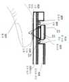
도1은 터치 스크린과 지문 센서를 장착한 모바일 기기(100)를 나타내는 단면 모식도이다.
도2a는 본원 발명에서 공개된 기술에 기반한 모바일 기기 또는 휴대 가능한 기기를 포함하는 여러가지 기기의 지문 검출 모듈의 터치 스크린 어셈블리를 집적시킨 것을 나타내는 모식도이다.
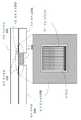
도2b는 도2a에서의 동그라미 부분의 표시 영역을 나타내는 확대도이고, 상기 설명한 일부 실시예들 중의 개구와 지문 센서 모듈을 포함한다.
도2c는 지문 센서 모듈(212)을 나타내는 평면도이다.
도2d는 터치 스크린과 지문 센서의 어셈블리의 일 실시예를 나타내고, 여기서 도2b 중의 금속링(228)은 다시 도전 필름으로 구성된다.
도3a는 터치 스크린과 지문 센서의 어셈블리 중의 강화 유리 커버의 일 실시예를 나타내는 평면도와 측면도이다.
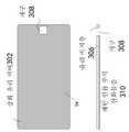
도3b는 터치 스크린과 지문 센서의 어셈블리 중의 유리 지지층의 일 실시예를 나타내는 평면도와 측면도이다.
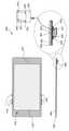
도4a 및 4b는 터치 스크린 어셈블리, 지문 센서 어셈블리 또는 터치 스크린과 지문 센서의 어셈블리의 집적 중의 강화 유리 커버의 일 실시예를 나타내는 평면도와 측면(단면)도이다.
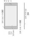
도5는 상술한 일부 실시예 중의 터치 스크린과 지문 센서의 어셈블리를 장착한 모바일 기기(예를 들어, 스마트폰, 태블릿 PC)를 나타내는 평면 모식도이다.
도6은 하기 설명된 일부 실시예 중의 터치 스크린과 지문 개구 어셈블리의 집적을 사용하여 지문 인증하는 개념을 나타낸다.
상이한 도면 사이의 유사한 참조 번호와 정의는 유사한 부재를 표시한다.1 is a schematic cross-sectional view showing a mobile device 100 equipped with a touch screen and a fingerprint sensor.
2A is a schematic diagram showing a touch screen assembly of a fingerprint detection module of various devices including a mobile device or a portable device based on the technique disclosed in the present invention.
FIG. 2B is an enlarged view showing a display area of a circle portion in FIG. 2A, and includes an aperture and a fingerprint sensor module in some of the embodiments described above.
2C is a plan view showing the fingerprint sensor module 212. FIG.
2D illustrates one embodiment of an assembly of a touch screen and a fingerprint sensor, wherein the
3A is a plan view and a side view showing one embodiment of a tempered glass cover in an assembly of a touch screen and a fingerprint sensor.
3B is a top view and a side view showing one embodiment of a glass support layer in an assembly of a touch screen and a fingerprint sensor.
4A and 4B are a top view and side view, respectively, of one embodiment of a tempered glass cover during the integration of a touch screen assembly, a fingerprint sensor assembly, or an assembly of a touch screen and a fingerprint sensor.
5 is a schematic plan view showing a mobile device (e.g., a smartphone, a tablet PC) equipped with an assembly of a touch screen and a fingerprint sensor in some of the embodiments described above.
Figure 6 illustrates the concept of fingerprint authentication using the integration of a touch screen and a fingerprint aperture assembly in some embodiments described below.
Like reference numerals and definitions between different drawings indicate like elements.
지문 인증 수단을 구비하는 전자 기기인 스마트폰, 태블릿 PC및 노트북과 같은 모바일 기기는 이미 자주 보아서 신기하지 않다. 더 많은 사용자들은 결국 지문 검출 능력을 구비한 모바일 기기를 획득하게 될 것이다. 현재, 일부 터치 스크린 디스플레이와 지문 검출 모듈을 동시에 구비한 모바일 기기는 물리적으로, 상기 터치 스크린 영역과 상기 인정 검출 모듈을 기기 표면의 상이한 영역에 분리된다. 또한, 상기 지문 검출 모듈은 기기 표면의 유리 커버를 통과하는 홀에 안착된다. 이러한 기기는 유리 커버가 상대적으로 비교적 두껍고, 홀이 정밀도가 높으며, 제작 제작 허용 오차가 매우 낮아야 한다. 지문 검출 모듈의 외관은 하나의 기계 버튼과 유사하고, 기계 버튼이 없는 터치 스크린 기기에 습관된 사용자한테는 시각적으로 매력이 없다.Mobile devices such as smart phones, tablet PCs, and notebooks, which are electronic devices equipped with fingerprint authentication means, are not often widespread. More users will eventually acquire mobile devices with fingerprint detection capabilities. At present, a mobile device having some touch screen displays and fingerprint detection modules at the same time physically separate the touch screen area and the recognition detection module into different areas of the device surface. Further, the fingerprint detection module is seated in a hole passing through the glass cover on the surface of the device. Such a device should have a comparatively thick glass cover, a high hole precision, and a very low manufacturing tolerance. The appearance of the fingerprint detection module is similar to that of a single mechanical button, and is not visually appealing to users who are habituated to touch screen devices without mechanical buttons.
본 발명에서 설명하는 실시예는 기기, 시스템 및 기술을 제공하여 지문 검출 모듈을 터치 스크린에 집적시켜 모바일 기기의 한 어셈블리로 하는 것이다. 상기 집적 터치 스크린과 지문 센서 어셈블리는 함께 접합되어 터치 스크린에 완전한 기계적 강도를 제공하는 적어도 두 개의 유리층을 포함한다. 상층 유리층은 강화/강화 유리 커버이고, 상기 유리층을 통과하고 지문 검출 모듈을 장착하기 위한 개구를 포함하지 않는다. 하층 유리층은 유리 지지층이고, 강화 유리 커버의 하방에 위치하며, 상기 터치 스크린과 지문 센서 어셈블리에 별도의 기계적 강도를 제공한다. 또한, 상기 유리 지지층은 상기 유리 지지층의 후미부에 근접한 개구를 포함한다. 상기 집적 터치 스크린과 지문 센서 어셈블리는 상기 유리 지지층의 개구 내에 위치한 지문 검출 모듈을 더 포함하고, 직접적으로 강화 유리 커버의 하방에 있다. 상기 집적 터치 스크린과 지문 센서 어셈블리는 강화 유리 커버의 표면에 형성된 지문 센서 마크에 더 포함되고, 상기 지문 검출 모듈의 상방에 위치하며, 지문 검출 모듈의 위치를 지시한다. 언급한 스크린과 지문 센서 어셈블리는 지문 센서에서의 강화 유리 커버를 통과하는 큰 홀을 제거하였기에 기기의 외관과 지문 센서의 성능 및 신뢰성, 공간 절약을 크게 상승시켰고, 또한 제조 원가를 대폭 절감하였다.The embodiments described in the present invention provide devices, systems, and techniques to integrate a fingerprint detection module on a touch screen to form an assembly of a mobile device. The integrated touch screen and the fingerprint sensor assembly include at least two glass layers joined together to provide the complete mechanical strength to the touch screen. The upper glass layer is a reinforced / tempered glass cover and does not include openings for passing through the glass layer and for mounting the fingerprint detection module. The lower glass layer is a glass support layer and is positioned below the tempered glass cover and provides separate mechanical strength to the touch screen and fingerprint sensor assembly. Further, the glass support layer includes an opening close to the rear portion of the glass support layer. The integrated touch screen and the fingerprint sensor assembly further include a fingerprint detection module located within the opening of the glass support layer and directly below the tempered glass cover. The integrated touch screen and the fingerprint sensor assembly are further included in a fingerprint sensor mark formed on the surface of the tempered glass cover and are positioned above the fingerprint detection module and indicate the position of the fingerprint detection module. The aforementioned screen and fingerprint sensor assembly greatly removed the large holes passing through the tempered glass cover of the fingerprint sensor, thus greatly improving the performance and reliability of the device and the fingerprint sensor, saving space and greatly reducing the manufacturing cost.
다른 한편으로는, 모바일 기기의 터치 스크린과 지문 센서의 어셈블리는 상기 터치 스크린과 지문 센서의 어셈블리의 상층에 위치한 강화 유리 커버를 포함한다. 상기 터치 스크린과 지문 센서의 어셈블리는 상기 강화 유리 커버의 하방에 위치하고 개구를 포함하는 유리 지지층을 더 포함한다. 상기 강화 유리 커버와 상기 유리 지지층은 함께 접합되어, 상기 터치 스크린과 지문 센서의 어셈블리의 기계적 강도를 지원하도록 제공한다. 상기 터치 스크린과 지문 센서의 어셈블리는 상기 유리 지지층의 개구 내에 위치한 지문 검출 모듈을 더 포함하고, 상기 강화 유리 커버의 하방에 위치한다.On the other hand, the touch screen of the mobile device and the assembly of the fingerprint sensor include a tempered glass cover located on the upper layer of the touch screen and the fingerprint sensor assembly. The assembly of the touch screen and the fingerprint sensor further includes a glass support layer located below the tempered glass cover and including an opening. The tempered glass cover and the glass support layer are joined together to provide mechanical strength of the touch screen and fingerprint sensor assembly. The assembly of the touch screen and the fingerprint sensor further includes a fingerprint detection module located within the opening of the glass support layer and is located below the tempered glass cover.
일부를 실현함에 있어서, 상기 터치 스크린과 지문 센서의 어셈블리는 강화 유리 커버의 표면에 형성되고, 상기 지문 검출 모듈의 상방에 위치하여, 지문 검출 모듈의 위치를 지시하는 지문 센서 마크를 더 포함한다.In some embodiments, the touch screen and the fingerprint sensor assembly are formed on the surface of the tempered glass cover, and further include a fingerprint sensor mark positioned above the fingerprint detection module and indicating the position of the fingerprint detection module.
다른 한편으로는, 지문 검출 수단을 집적시킨 터치 스크린 전자 기기는 프레임과 상기 터치 스크린과 지문 센서의 어셈블리는 프레임에 의해 둘려싸여 보호되는 터치 스크린 어셈블리를 포함한다. 상기 터치 스크린과 지문 센서의 어셈블리는, 상기 터치 스크린과 지문 센서의 어셈블리의 최상층에 위치하고 물체와의 접촉을 수신하기 위한 강화 유리 커버; 상기 유리 지지층을 통과하는 개구를 포함하는 강화 유리 커버의 하면의 유리 지지층; 상기 유리 지지층의 개구 내에 위치하고 상기 강화 유리 커버의 하방에 위치하는 지문 검출 모듈을 포함하고, 여기서 상기 강화 유리 커버와 상기 유리 지지층은 하나로 접착되어, 상기 터치 스크린 어셈블리의 기계적 강도를 지원하도록 제공되며, 상기 터치 스크린 전자 기기는 상기 터치 스크린 어셈블리와 상기 프레임의 후면 커버 사이의 주 회로 기판을 더 포함한다.On the other hand, a touch screen electronic device incorporating fingerprint detection means includes a frame and a touch screen assembly in which an assembly of the touch screen and the fingerprint sensor is surrounded and protected by a frame. The assembly of the touch screen and the fingerprint sensor includes: a tempered glass cover positioned on the uppermost layer of the touch screen and the fingerprint sensor assembly for receiving contact with an object; A glass support layer on the lower surface of the tempered glass cover including an opening through the glass support layer; And a fingerprint detection module positioned within the opening of the glass support layer and positioned below the tempered glass cover wherein the tempered glass cover and the glass support layer are bonded together to provide a mechanical strength of the touch screen assembly, The touch screen electronic device further includes a main circuit board between the touch screen assembly and the back cover of the frame.
다른 한편으로는, 지문 센서 모듈이 장착된 개구가 없는 강화 유리 커버를 준비하는 단계; 지문 센서 모듈이 장착된 개구가 있는 유리 지지층을 준비하는 단계; 상기 강화 유리 커버와 상기 유리 지지층을 접착시키고, 상기 강화 유리 커버와 상기 유리 지지층은 터치 스크린 어셈블리를 지지하는 기계적 강도를 함께 제공하는 접착 단계; 및 하나의 지문 검출 모듈을 상기 유리 지지층의 개구 내에 설치하고, 상기 지문 검출 모듈을 상기 강화 유리 커버의 하측에 연결시키는 단계를 포함하는 것을 특징으로 하는 터치 스크린 어셈블리의 조립 방법을 제공한다.On the other hand, preparing a tempered glass cover without an opening in which a fingerprint sensor module is mounted; Preparing a glass support layer having an opening in which a fingerprint sensor module is mounted; Bonding the tempered glass cover and the glass support layer, the tempered glass cover and the glass support layer providing mechanical strength to support the touch screen assembly; And installing one fingerprint detection module in the opening of the glass support layer and connecting the fingerprint detection module to the lower side of the tempered glass cover.
도1은 터치 스크린과 지문 센서를 장착한 모바일 기기(100)를 나타내는 단면 모식도이다. 상기 모바일 기기(100)는 공간적으로 연속된 유리 표면을 구비하여, 상기 터치 민감 영역 및 상기 지문 센서 모듈을 완전히 커버하는 강화/강화 유리 커버(102)를 포함한다. 강화 유리 커버(102)는 상기 모바일 기기(100)의 표면의 주요 부분을 차지하는 정전 용량 터치 영역(104)을 포함하고, 아래의 터치 스크린 디스플레이 어셈블리를 구현하였기에, 터치 민감 표면을 제공하였다. 구체적으로, 정전 용량 터치 영역(104)은 얇은 유리/필름층(106)과 하나의 LCD 디스플레이 모듈(108)의 상방에 위치하여, 상기 터치 스크린 디스플레이 어셈블리를 형성하고, 여기서 상기 얇은 유리/필름층(106)은 강화 유리 커버(102)의 정전 용량 터치 영역(104)의 하방에 위치하여, 정전 용량 터치 감응을 위해 정전 용량 터치 영역(104)과 접촉한다. 더 구체적으로, 하나 또는 두 개의 얇은 유리/필름층(106)의 표면에 패턴이 있는 인듐 주석 산화물(ITO)층이 코팅되어 있어, 정전 용량 터치 감지 기능을 오픈시킨다. 상기 강화 유리 커버(102)는 터치 스크린 구조로 디자인되어 필요한 기계적 강도의 기계적 지지를 제공하는 것을 유의해야 한다.1 is a schematic cross-sectional view showing a mobile device 100 equipped with a touch screen and a fingerprint sensor. The mobile device 100 includes a reinforced / tempered
강화 유리 커버(102)는 정전 용량 터치 영역(104) 외부의 영역에 위치한 개구(110)를 포함하고, 지문 검출 모듈(112)이 통과하기에 적합하다. 상기 지문 검출 모듈(112)은 개구(110)에 위치하는 지문 감응 상표면을 포함하고, 실행 방법은 손가락 터치 감응 상표면에 기반하여 터치 부분의 지문을 감응한다. 지문 검출 모듈(112)의 표면은 개구(110)를 통과하여 손가락의 직접적인 접촉을 수신하도록 외부로 노출되어 있다. 개구(110)는 강화 유리 커버(102)의 가장자리에 접근할 수 있다. 비교적 두꺼운(예컨대, 550μm 내지 750μm) 유리 커버를 통과하는 개구(110)를 제작하는데 초고도의 정밀도가 수요될 뿐만아니라, 제작 수익에 소극적인 영향을 일으킬 수 있다. 일부 실시예에 있어서, 강화 유리 커버(102)의 강과 과정에 앞서 개구(110)는 유리 커버에 형성되어 있다.The tempered
도2a는 본 발명에서 공개된 기술에 기반하여 모바일 기기 또는 휴대 가능한 기기를 포함하는 여러가지 기기의 지문 검출 모듈의 터치 스크린 어셈블리를 집적시킨 것을 나타내는 모식도이다. 도1에서의 디자인과 상이하게, 강화 유리 상방 커버에는 지문 감지 상부 표면을 노출시키는 개구가 없다. 반대로, 상기 지문 센서는 강화 유리 상방 커버의 하면에 완전히 숨겨져 있고, 개구를 통해 직접적으로 노출되지 않으며, 손가락으로 직접 터치하여 손가락의 지문을 감응하도록 디자인되지 않았다. 더 구체적으로, 도2a는 본원 발명에 따라 일부 실시예 중의 설명된 터치 스크린과 지문 검출 모듈의 모바일 기기의 터치 스크린 어셈블리(200)를 집적시킨 것을 나타내는 단면 모식도이다. 도2a에 도시된 바와 같이, 터치 스크린 어셈블리(200)는 상기 터치 스크린 어셈블리의 터치 민감 영역 및 표면이 터치 민감 영역이 아닌 기타 영역을 보호하기 위한 강화 유리 커버(202)를 포함한다. 본 디자인 중의 상기 지문 센서는 지문을 통해 강화 유리 커버(202)의 상부 표면을 터치할 수 있고 지문 세선의 상부면을 직접적으로 접촉하는 것으로 지문을 감응하지 않는다. 이는 강화 유리 커버(202)가 공간적으로 연속된 개구가 없는 유리 표면 하에서의 터치 스크린 어셈블리와 지문 센서에 완전히 커버된다. 일부 실시예에 있어서, 강화 유리 커버(202)의 두께는 100μm 내지 400μm 사이이다. 강화 유리 커버(202)의 두께를 선택하는 것에 관하여 아래에 추가적으로 토론하도록 한다. 강화 유리 커버(202)는 도1에 도시된 모바일 기기의 강화 유리 커버(102)와 기본적으로 동일한 재료 및/또는 과정으로 제작된다. 그러나, 강화 유리 커버(102)와 비교하면, 강화 유리 커버(202)도 일부 상이한 점을 포함한다.2A is a schematic diagram showing the integration of a touch screen assembly of a fingerprint detection module of various devices including a mobile device or a portable device based on the technique disclosed in the present invention. Unlike the design in FIG. 1, the tempered glass top cover does not have an opening to expose the fingerprint sensing top surface. Conversely, the fingerprint sensor is completely hidden on the lower surface of the tempered glass top cover, is not directly exposed through the opening, and is not designed to touch the fingerprint of the finger by touching directly with the finger. More specifically, FIG. 2A is a cross-sectional schematic diagram illustrating the integration of the touch screen assembly 200 of the mobile device of the fingerprint detection module with the touch screen described in some embodiments in accordance with the present invention. As shown in FIG. 2A, the touch screen assembly 200 includes a touch sensitive area of the touch screen assembly and a tempered
강화 유리 커버(202)는 강화 유리 커버(102)에서의 지문 검출 모듈 장착하기 위한 개구를 포함하지 않는다는 것을 유의해야 한다. 지문 센서용 개구의 드릴링 과정을 제거하였기에, 강화 유리 커버(202)의 가공은 도1에서의 개구가 있는 강화 유리 커버(102)의 가공에 비해 더 간단하다. 이 밖에, 개구를 제거하는 것은 사파이어보다 싼 재료와 강화 유리 커버(202)를 위한 유리 커버의 재료의 선택함에 있어서 더욱 자유롭다. 강화 유리 커버(202)의 제작 간소화는 강화 유리 커버(202)의 두께가 강화 유리 커버(102)보다 선명하게 얇도록 한다. 예를 들어, 강화 유리 커버(202)는 기계적 완전성에 영향을 일으키지 않는 상황하에서, 되도록 얇게 제작한다. 비교적 얇은 강화 유리 커버(202)는 제작 비용과 처리 시간을 저감시킬 수 있다. 일부 실시예에 있어서, 강화 유리 커버(202)의 하변(즉, 터치면의 반대면)에 컬러 에폭시층(204)을 코팅할 수 있는 바, 검은색, 흰색 또는 기타 색상일 수 있다. 컬러 에폭시층(204)은 특수한 패턴으로 구성될 수도 있다.It should be noted that the tempered
또한 도2a에 도시된 바와 같이, 터치 스크린 어셈블리(200)는 상기 강화 유리 커버(202)의 하방에 위치하고 상기 유리 지지층의 홀 또는 개구(208)(유리 지지층(206)의 개구(208)의 확대도는 도2b를 참조)를 통과하는 유리 지지층(206)을 더 포함한다. 일부 실시예에 있어서, 유리 지지층(206)의 두께는 100μm 내지 400μm 사이이다. 유리 지지층(206)의 두께는 강화 유리 커버(202)보다 크거나 작다. 일부 실현함에 있어서, 유리 지지층(206)의 두께는 강화 유리 커버(202)의 두께보다 선명하게 두껍다. 개구(208)의 유리 지지층(206)에서의 위치는 유리 지지층(206)의 말단 부분에 근접할 수 있고, 도1에서의 강화 유리 커버의 개구(110)의 상대적인 위치와 유사하다. 일부 실시예에 있어서, 개구(208)의 크기는 5mm x 5mm 크고, 개구(208)의 형태는 사각형, 원형 또는 기타 형태일 수 있다. 유리 지지층(206)은 템퍼링 강화 또는 무강화 처리로 진행될 수 있다. 강화 처리를 사용하면, 전형적으로 개구(208)를 제작한 후에 진행한다. 유리 지지층(206)의 저면에 패턴 인듐 주석 산화물층(210)이 코팅되어 있고, 이는 강화 유리 커버(202)에 터치 감응 기능이 있는 영역을 정의하였다.2A, the touchscreen assembly 200 is positioned below the tempered
도2a에 도시된 바와 같이, 강화 유리 커버(202)와 유리 지지층(206)은 함께 접합되어, 완전한 유리 커버 구조를 형성하고, 이는 선명하게 하나의 강화 유리 커버(202)와 유리 지지층(206)보다 두껍고 기계적 강도가 크다. 상기 두 개의 유리층은 하나의 에폭시층과 같은 얇은 접착제층과 접합될 수 있다. 상기 결합 구조의 두께는 도1 중의 강화 유리 커버(102)의 두께에 해당된다.2A, the tempered
터치 스크린 어셈블리(200)는 상기 유리 지지층(206)의 개구(208) 내에 위치한 지문 센서 모듈(212)을 더 포함할 수 있고, 상기 강화 유리 커버(202)의 하방에 위치한다. 지문 센서 모듈(212)은 강화 유리 커버(202)와 유리 지지층(206)이 함께 접합될 경우, 개구(208)를 통해 강화 유리 커버(202)에 접착될 수 있다. 지문 센서 모듈(212)은 강화 유리 커버(202)와 유리 지지층(206)이 함께 접합된 후, 개구(208)를 통해 강화 유리 커버(202)에 접착될 수 있다.The touch screen assembly 200 may further include a fingerprint sensor module 212 positioned within the
본 발명에서 설명된 실시예들에 있어서, 도2b는 도2a에서 동그라미(211) 부분의 표시 영역을 나타내는 확대도이고, 상술한 실시예들 중에서의 개구(208)와 지문 센서 모듈(212)을 포함한다. 지문 센서 모듈(212)은 아주 얇은 접착제층(214)에 의해 컬러 에폭시층(204)에 접착된다. 도2b에 도시된 바와 같이, 지문 센서 모듈(212)은 개구(208)에 긴밀하게 장착될 필요가 없이, 모듈의 가장자리와 개구(208)의 가장자리의 사이에 틈새가 있음을 유의해야 한다. 이 틈새는 지문 센서 모듈(212)이 강화 유리 커버(202) 및 유리 지지층(206)에 집적시킬 경우, 큰 집적 공차가 있다. 이렇게 강화 유리 커버(202), 유리 지지층(206)와 지문 센서 모듈(212)은 하나의 터치 스크린와 지문 검출 어셈블리의 집적을 이룬다. 대조적으로, 도1의 실시예에서 지문 센서 모듈102은 물리적으로, 기계적으로 터치 스크린과 구조적 분리를 이룬다.2B is an enlarged view showing a display area of a portion indicated by a
본 발명의 일 일부 실현함에 있어서, 지문 센서 모듈(212)은 인쇄 회로 기판(PCB)(214)를 포함하고, 지문 데이터를 수집하기 위한 집적회로와 지문 센서 칩(216)이 있으며, 여기서 지문 센서 칩(216)의 상부 표면은 컬러 에폭시층(204)에 접착되고, 동시에 지문 센서 칩(216)의 하부 표면의 인쇄 회로 기판(214)의 상부 표면에 접착된다. 지문 센서 모듈(212)은 플렉시블 인쇄 회로 (FPC)(218)도 포함하여, 인쇄 회로 기판(214)의 하부 표면에 접착되어 지문 센서 칩(216)에 의해 수집된 지문 센서 신호를 모바일 기기의 주 회로 기판(미표시)에 커플링되도록 한다. 지문 센서 칩(216)이 강화 유리 커버(202)의 하면에 위치하고 있어, 지문 감지는 강화 유리 커버(202)에 의해 만들어진 틈새를 통해 정전 용량을 완성하며, 이는 강화 유리 커버(202)의 두께의 디자인이 제한되도록 한다. 일 실시예에서, 강화 유리 커버(202)의 두께는 고민감도가 요구되는 얇은 유리와 고기계적 강도가 요구되는 두꺼운 유리 사이의 평형에 의해 결정된다.In some implementations of the present invention, the fingerprint sensor module 212 includes a printed circuit board (PCB) 214 and an integrated circuit and
도2c는 본 발명에서 설명한 일부 실시예에 있어서의 지문 센서 모듈(212)를 나타내는 평면 모식도이다. 도2c에서 볼 수 있는 바와 같이, 지문 센서 모듈(212)은 인쇄 회로 기판(214)의 상부 표면에 고정된 발광 다이오드(LEDs)(224)와 같은 분리된 부재가 포함된다. 지문 센서 모듈(212)는 광 검출기도 포함되어, 예를 들어, 포토 다이오드(226) 및 신호 처리 모듈(미표시)이 접촉된 지문 센서 모듈(212)의 물체가 사람인지 아닌지의 여부를 수집하고 결정한다. 발광 다이오드와 광 검출기로 사람를 검출하는 것에 관한 더 구체적인 설명은 미국에서 제출일자가 2013년 11월 22일자이고 출원번호가 61/908,026인 특허, "사람 지문 검출 모듈"에서 설명되어 있고, 상기 특허는 본 발명에 결부 인용되어, 본 발명의 공개된 일부분으로 한다. 사람의 검출 외에, 발광 다이오드(224)와 같은 상기 분리 부재 및 포토 다이오드(226)와 같은 상기 집적 광 검출기도 심장 박동, 사용자 혈중 산소 포화도 레벨(SpO2) 및 기타와 같은 인체 생체 인식 신호로 사용될 수 있다.2C is a schematic plan view showing the fingerprint sensor module 212 in some embodiments of the present invention. As can be seen in FIG. 2C, the fingerprint sensor module 212 includes a separate member, such as light emitting diodes (LEDs) 224, secured to the upper surface of the printed
지문 검출 모듈(212)은 지문 센서 칩(216)을 감싸는 금속링(228)을 더 포함할 수 있고, 상기 금속층(228)은 컬러 에폭시층(204)에 접착된다. 지문 검출 모듈(212)의 나머지 부분과 유사하게, 금속링(228)은 얇은 접착층에 의해 컬러 에폭시층(204)에 접착될 수 있다. 일 실시예에서, 금속링(228)은 정전 용량 터치 센서의 일부분으로서, 물체와 강화 유리 커버(202)의 접촉을 검출하기 위한 것이다. 예를 들어, 금속링(228)은 감지 전극으로서 사람의 손가략 또는 물체가 지문 검출 모듈(212)에 접촉되었는지의 여부를 검출하는 일부 실시예에 있어서, 금속링(228)은 신호 전극으로도 될 수 있다. 예를 들어, 한 기기로부터 기기 통신 설치까지, 금속링(228)은 발송 및 수신 전극으로서, 다른 정전 용량 터치 스크린의 정전 용량 커플링 단자에 전기 신호를 발송 및 수신한다.The fingerprint detection module 212 may further include a
도2b의 실시예에서, 금속링(228)은 전체가 개구(208) 내에 위치한다. 이러한 구성은 두가지 후과를 초래한다. 즉, 개구(208)의 크기가 반드시 금속링(228)을 포함할 수 있을 정도로 커야 하고; 하지만 개구(208)의 크기가 표시 영역에 영향주기 때문에 금속링(228)의 크기는 너무 커서는 안된다. 하지만, 특히, 지문 센서가 강화 유리 커버(202)의 하방에 위치할 경우, 큰 금속링은 정전 용량 감응의 민감도를 증가하는데 도움이 된다.In the embodiment of FIG. 2B, the
도2d는 터치 스크린과 지문 센서의 어셈블리의 일 실시예를 나타내고, 여기서 도2b에서의 금속링(228)은 새롭게 도전 필름으로 구성된다. 도2d에서 볼 수 있는 바와 같이, 전기 전도링층(230)은 강화 유리 커버(202)와 유리 지지층(206) 사이에 끼워져 있다. 유리 지지층(206)의 개구(208)는 충분히 금속링(228)이 없는 지문 검출 모듈(212)을 수용할 수 있는 정도로 맞춤하게 크도록 제작할 수 있다. 전기 전도링층(230)은 개구(208) 내에 한정되지 않고, 링층(230)의 표면은 금속링(228)보다 클 수 있다. 예를 들어, 도2d도 전기 전도링층(230)과 지문 검출 모듈(212)을 나타내는 평면 모식도이다. 일 실시예에 있어서, 전기 전도링층(230)은 강화 유리 커버(202)의 컬러 에폭시층에 실크 인쇄를 진행하고, 틈새(232)를 통해 지문 검출 모듈(212)과 격리된다.2d shows an embodiment of an assembly of a touch screen and a fingerprint sensor, wherein the
도3a는 터치 스크린과 지문 센서의 어셈블리에서의 강화 유리 커버의 일 실시예를 나타내는 평면도 및 측면도이다. 도3a에 도시된 바와 같이, 강화 유리 커버(302)는 강화 유리 커버(302)를 통과하여 지문 센서 모듈이 장착된 개구가 없다. 하지만, 지문 센서 위치는 센서 마크(303)에 의해 강화 유리 커버(302)에 마크되고, 예를 들어, 일 인쇄마크로 한다. 센서 마크(303)은 사용자의 손가락이 강화 유리 하방에 장착된 지문 센서 칩으로 인도하도록 도와준다. 강화 유리 커버(302)의 저면에는 컬러 에폭시층(304)가 코팅되어, 강화 유리 커버(302) 하에 위치한 지문 검출 모듈을 감추도록 구성될 수 있다. 터치 민감 영역(305)은 지문 센서 위치와 일치되지 않음을 유의해야 한다.3A is a plan view and a side view showing one embodiment of a tempered glass cover in an assembly of a touch screen and a fingerprint sensor. 3A, the tempered glass cover 302 passes through the tempered glass cover 302 and does not have an opening in which the fingerprint sensor module is mounted. However, the position of the fingerprint sensor is marked on the tempered glass cover 302 by the sensor mark 303, for example, one print mark. The sensor mark 303 helps guide the user's finger to the fingerprint sensor chip mounted below the tempered glass. The bottom surface of the tempered glass cover 302 may be coated with a
도3b는 터치 스크린과 지문 센서의 어셈블리에서의 유리 지지층의 일 실시예를 나타내는 평면도와 측면도이다. 도3b에 도시된 바와 같이, 유리 지지층(306)은 개구(308)와 센서 마크(303)의 일치가 포함된다. 유리 지지층(306)의 저면에 패턴 인듐 주석 산화물층(310)이 코팅되어 있어, 강화 유리 커버(302) 상에 터치된 터치 감응 기능의 영역을 정의한다.Figure 3b is a top view and side view of one embodiment of a glass support layer in an assembly of a touch screen and a fingerprint sensor. As shown in FIG. 3B, the
도2a에서의 터치 스크린과 지문 센서의 어셈블리를 획득하기 위해, 도3b에서의 유리 지지층(306)과 도3a에서의 강화 유리 커버를 접착시켜, 예를 들어, 에폭시로 접착시키며, 여기서, 컬러 에폭시층(304)는 두 개의 유리층 사이에 끼워 있다. 이어서, 지문 검출 모듈은 개구(308)를 통해 강화 유리 커버(302)의 하부 표면에 접착되어, 예를 들어, 동일한 에폭시로 접착시켜 상기 터치 스크린과 지문 센서의 어셈블리를 완선한다. 본 발명에서 공개된 터치 스크린과 지문 센서의 어셈블리의 다층 구조는 상층 유리층에서의 지문 센서 위치의 통공을 제거하여, 기기의 외관과 지문 센서 성능 및 신뢰성을 제고시키고, 공간 절약하는 동시에 제작 비용을 크게 절감시킨다.To obtain the touch screen and fingerprint sensor assembly in FIG. 2A, the
상기 터치 스크린과 지문 센서 어셈블리의 집적은 모바일 기기의 최종 집적지와 다른 장소에서 모듈로 제작될 수 있다. 개구(308)는 에폭시층(304)으로 사용자한테 감추어, 유리 지지층(306)을 통과하여 개구(308)를 드릴링하는 것은 도1에서의 개구(106)와 같은 동일한 레벨의 정밀도(예를 들어, 무기 위치, 크기 및 거칠기)가 필요없으므로, 제작 비용과 처리 시간을 절감하는 동시에 생산량을 높인다.The integration of the touch screen and the fingerprint sensor assembly may be modularly fabricated at a location other than the final integration site of the mobile device. The
도4a 및 4b는 터치 스크린 어셈블리, 지문 센서 어셈블리 또는 터치 스크린과 지문 센서의 어셈블리의 집적에서의 강화 유리 커버의 일 실시예를 나타내는 평면도 및 측면(단면)도이다. 도4a 및 4b에서 도시된 바와 같은 간소화 강화 유리 커버의 일부 실현함에 있어서, 강화 유리 커버의 구조는 간소화된 것은 강화 유리 커버가 충분하게 견고하여, 유리 지지층이 필요없기 때문이다. 지지층이 적어진 후, 터치 감응 기능(예를 들어, 터치 센서 또는 지문 센서 또는 터치와 지문 센서의 집적)의 전기 회로는 직접적으로 유리 커버(450)의 저면에 또는 유리 커버(450)의 저면에 접착된 고분자 박막에 구현될 수 있다. 인셀(in-cell, 표시 셀)터치 해결 방법에서는 터치 감응 기능의 전기 회로가 유리 커버(450)의 저면에 회전 또는 접착된 액정 디스플레이 모듈에 구현 또는 집적된다. 지지층을 제거하는 것을 통해, 터치 감응을 제공하는 전기 회로를 포함하는 강화 유리 커버가 크게 간소화되었다.Figures 4a and 4b are top and side (cross-sectional) views illustrating one embodiment of a tempered glass cover in the integration of a touch screen assembly, a fingerprint sensor assembly, or an assembly of a touch screen and a fingerprint sensor. In the partial realization of the simplified tempered glass cover as shown in Figs. 4A and 4B, the structure of the tempered glass cover is simplified because the tempered glass cover is sufficiently rigid and no glass support layer is required. The electrical circuit of the touch sensitive function (e.g., a touch sensor or a fingerprint sensor or the integration of the touch and fingerprint sensors) is directly placed on the bottom of the
간소화된 강화 유리 커버는 모바일 기기(400)에 구현된다. 예를 들어, 상기 강화 유리 커버는 지문 센서 모듈을 집적한 터치 패널 어셈블리(410)의 일부분으로 구현할 수 있다. 모바일 기기(400)에서 기타 센서의 위치(412)도 물리적 버튼(414, 416)(예를 들어, 측면 가장자리 버튼)의 실시예와 동시에 표시된다. 일부 실현함에 있어서, 지문 센서 마크(421)은 터치 패널 어셈블리(410)에 또는 부근에 표시될 수 있다. 지문 센서 칩(423)은 집적회로를 가진 배면 인쇄 회로 기판에 구성될 수 있다. 배면 인쇄 회로 기판(425)는 플렉시블 인쇄 회로(FPC)(427)에 구성될 수 있다. 일부 실현함에 있어서, 컬러 에폭시 재료층(452)는 유리 커버(450)의 배면에 제공될 수 있고, 하기와 같은 기능이 있다. (1) 접합 재료, (2) 필요한 외관 색상을 제공한다. 한 공간에서, 예를 들어, 지문 센서 모듈에 공간을 제공하는 홀(458)은 유리 커버(450)의 하방(및 컬러 에폭시 재료층(452)을 포함할 경우, 컬러 에폭시 재표층의 하방에 있다)에 구성된다. 일부 실현함에 있어서, 금속링 구조(429)는 유리 커버(450)(및 컬러 에폭시 재료층(452)이 포함될 경우)의 하면에 접착될 수 있으며, 지문 센서 칩(423)을 감싸거나 근접할 수 있다. 일부 실현함에 있어서, 얇은 에폭시 재료(431)는 지문 센서를 유리 커버(450)(또는 컬러 에폭시 재료층(452), 포함될 경우)에 접착시킨다. 발광 다이오드와 같은 분리 부재(433)는 인쇄 회로 기판(425)의 저면에 고정될 수 있다. 또한, 포토 다이오드와 같은 광 검출기(435)는 인쇄 회로 기판(425), 지문 센서 칩(423) 또는 이 두가지에 구성될 수 있다. 일부 실현함에 있어서, 강화 유리 커버(450)의 두께는 100μm 내지 300μm일 수 있다.The simplified tempered glass cover is implemented in the
도4b는 터치 스크린 어셈블리, 지문 센서 어셈블리 또는 집적 터치 스크린과 지문 센서 어셈블리의 간소화 강화 유리 커버를 나타내는 측면(단면)도이다. 강화 유리 커버(450)의 일부분은 홈 구조(예를 들어, 하나의 공간)로 에칭되어 공간을 제공하거나 상기 지문 센서 모듈 또는 상기 지문 센서 모듈의 지문 센서 칩 부재(423)일 수 있다.4B is a side (cross-sectional) view illustrating a simplified, tempered glass cover of a touch screen assembly, fingerprint sensor assembly or integrated touch screen and fingerprint sensor assembly. A portion of the tempered
도5는 상술한 실시예 중의 터치 스크린과 지문 센서의 어셈블리를 조립한 모바일 기기(500)(예를 들어, 스마트폰, 태블릿 PC)를 나타내는 평면 모식도이다. 도5 및 도2a 내지 도2d, 도3a 내지 도3b 및 도4a 내지 도4b에 도시된 바와 같이, 모바일 기기(500)는 상술한 집적 터치 스크린과 지문 검출 모듈 어셈블리(502)를 포함한다. 모바일 기기(500)는 측변 가장자리 버튼(504, 506)을 더 포함하고, 여기서 버튼들은 지문 감응과 검출 작동을 제어하도록 구성된다. 상기 지문 검출 모듈(보이지 않음)은 부호(508)로 유리 커버에 마킹된다. 터치 스크린과 지문 검출 모듈을 집적시킨 어셈블리(502)는 센서(510)과 같은 기타 센서를 위해 기타 구조 위치를 제공한다.5 is a schematic plan view showing a mobile device 500 (for example, a smart phone, a tablet PC) in which an assembly of a touch screen and a fingerprint sensor in the above-described embodiment is assembled. As shown in FIGS. 5 and 2A-2D, 3A-3B and 4A-4B, the mobile device 500 includes the above-described integrated touch screen and fingerprint detection module assembly 502. The mobile device 500 further includes side edge buttons 504 and 506, wherein the buttons are configured to control fingerprint sensing and sensing operations. The fingerprint detection module (not shown) is marked 508 on the glass cover. The assembly 502 integrating the touch screen and the fingerprint detection module provides other structural locations for other sensors, such as the sensor 510.
도6은 본 발명에 따라 설명된 일부 실시예 중의 터치 스크린과 지문 센서 어셈블리의 집적(대체적으로, 도2b 중의 터치 스크린과 지문 센서 어셈블리의 집적과 유사함)을 사용하여 지문 인증하는 개념을 나타낸다.Figure 6 illustrates the concept of fingerprint authentication using the integration of a touch screen and fingerprint sensor assembly in some embodiments described in accordance with the present invention (generally similar to the integration of a touch screen and fingerprint sensor assembly in Figure 2b).
상술한 바와 같이, 터치 스크린과 지문 센서 어셈블리의 집적에서의 지문 검출 모듈은 유리 지지층(606)의 개구(608) 내에 구성된다. 지문 검출 모듈은 인쇄 회로 기판(614), 지문 센서 칩(616) 및 플렉시블 인쇄 회로(618)를 포함하되, 여기서 지문 센서 칩(616)은 금속링(628)에 의해 둘러 싸인다. 또한, 지문 검출 모듈은 하나 또는 복수개의 인쇄 회로 기판(614)의 상부 표면에 장착된 발광 다이오드(624) 및 하나 또는 복수개의 지문 센서 칩(616)에 집적된 발광 다이오드(626)를 포함한다.As described above, the fingerprint detection module in the integration of the touch screen and the fingerprint sensor assembly is configured within the
일부 실현함에 있어서, 사람의 손가락과 같은 물체(630)가 강화 유리 커버(602)에 센서 마크(603)에 의해 지시된 위치에 접촉할 경우, 금속링(628)은 강화 유리 커버(602)의 정전 용량을 통해 커플링된 신호를 검출하고 발광 다이오드(624)를 활성화시켜 검출광을 방출한다. 검출광이 물체(630)에 의해 반사되고, 반사광은 발광 다이오드(626)에 의해 수신되고 측정된다. 이러한 발광 다이오드(624, 626) 및 신호 처리 모듈(미표시)이 함께 생체 인식 신호, 예를 들어, 심장박동, 사용자의 혈중 산소 포화도 레벨(SpO2) 및 기타를 측정하는 것을 통해, 물체(630)가 사람인지의 여부를 판단한다. 사람을 검출하는 과정이 완성되면, 표준 지문 인증 과정이 지문 검출 모듈을 통해 진행되기 시작한다.In some realizations, when an object 630, such as a human finger, touches the tempered glass cover 602 at the location indicated by the
본 출원 서류 중의 상이한 터치 스크린과 지문 센서의 어셈블리의 구현은 여러가지 시스템 및 기기는 휴대전화, 태블릿 PC, 휴대용 컴퓨터, 무선 기기, 노트북, 게임기 및 멀티미디어를 포함하지만 이에 한정되지는 않는다.Implementation of different touchscreen and fingerprint sensor assemblies in the present application includes, but is not limited to, mobile phones, tablet PCs, portable computers, wireless devices, notebooks, gaming devices and multimedia.
상기 출원 문헌에는 많은 세부사항이 포함되지만, 이는 어떠한 발명 또는 보호받고자 하는 범위를 한정하는 것으로 해석하여서는 아니되고, 특징의 설명으로 해야 하며, 특정 발명의 특정 실시예의 구체적인 설명일 수 있다. 이 출원 문헌에서는 단독 실시예의 상하 문장에서 설명한 어느 특징도 하나의 실시예와 결부하여 실현될 수 있다. 반대로, 하나의 실시예의 상하 문장에서 설명한 각종 특징은 단독적으로 복수개의 실시예 또는 어떠한 적합한 서브 조합으로 실현될 수 있다. 이 밖에, 상기 설명된 특징과 어느 한 결합에서 일으키는 작용이 동일하지만, 지어는 최초로 상기와 같이 주장할지라도, 요구되는 결합 중의 하나 또는 복수개의 특징이 어느 상황에서 결합으로부터 제거될 수 있으면, 또한 보호받고자 하는 결합이 하나의 서브 조합 또는 하나의 서브 조합의 변형체에 한할 수 있다.While the foregoing application contains many details, it should not be construed as limiting the scope of any invention or protection, but merely as a description of features, and may be a specific description of a particular embodiment of a particular invention. In this application document, any of the features described in the upper and lower sentences of the independent embodiment can be realized in conjunction with one embodiment. On the contrary, the various features described in the upper and lower sentences of one embodiment can be realized as a plurality of embodiments alone or in any suitable subcombination. In addition, although the action caused in any combination of the above-described features is the same, even if the first claim is made as above, if one or more of the required combinations can be removed from the combination in any situation, The combination to be received may be limited to one subcombination or a variant of one subcombination.
유사하게는, 비록 작동은 특정된 순서로 도면에서 서술되지만, 이는 이러한 작동이 도시된 특정 순서 또는 연속적인 순서로써 실행되는 것을 요구하는 것이 아니거나, 또는 도시된 작동이 모두 실행되어 원하는 결과를 달성시키는 것으로 이해해서는 아니된다. 이 밖에, 상기 특허 문헌에서 서술되는 실시예의 각종 시스템 부의 분리는 모든 부재들의 분리를 요구하는 것이 아니다.Similarly, although operations are described in the figures in a particular order, it is to be understood that this is not required to be performed in the specific order shown or in a sequenced order, or that all of the depicted operations are performed to achieve the desired result It should not be understood that it is. In addition, the separation of various system parts of the embodiment described in the above patent documents does not require separation of all members.
본 명세서는 일부 실시행태 및 실시예를 설명하였을뿐, 기타 실시행태, 개선 및 변형은 모두 본 명세서의 설명에 기반하여 획득할 수 있다.This specification has described some embodiments and examples, and other embodiments, improvements, and modifications may all be made based on the description herein.
Claims (43)
Translated fromKorean상기 강화 유리 커버의 하방에 위치하고 개구를 포함하는 유리 지지층; 및
상기 유리 지지층의 개구 내에 위치하고, 상기 강화 유리 커버의 하방에 위치하는 지문 검출 모듈을 포함하되,
상기 개구는 상기 유리 지지층을 통과하고,
상기 강화 유리 커버와 상기 유리 지지층은 하나로 접착되어, 상기 터치 스크린 어셈블리의 기계적 강도를 지원하도록 제공되는 것을 특징으로 하는 모바일 기기용 터치 스크린 어셈블리.A tempered glass cover located on top of the touch screen assembly;
A glass support layer located below the tempered glass cover and including an opening; And
A fingerprint detection module located within the opening of the glass support layer and positioned below the tempered glass cover,
Said opening passing through said glass support layer,
Wherein the tempered glass cover and the glass support layer are adhered together to provide a mechanical strength of the touch screen assembly.
집적회로의 인쇄 회로 기판; 및
지문 데이터를 수집하기 위한 지문 센서 칩을 포함하되,
상기 지문 센서 칩의 제1 가장자리는 인쇄 회로 기판에 부착되고, 상기 지문 센서 칩의 제2 가장자리는 색상층, 패턴층 또는 색상패턴 복합층에 연결되는 것을 특징으로 하는 터치 스크린 어셈블리.The fingerprint detection module according to claim 1,
A printed circuit board of an integrated circuit; And
A fingerprint sensor chip for collecting fingerprint data,
Wherein a first edge of the fingerprint sensor chip is attached to a printed circuit board and a second edge of the fingerprint sensor chip is connected to a color layer, a pattern layer or a color pattern composite layer.
검출광을 발사하도록 구성되는 하나 또는 복수개의 광원; 및
하나 또는 복수개의 생체 인식 신호를 모니터링하도록 구성되는 하나 또는 복수개의 바이오 센서를 더 포함하는 것을 특징으로 하는 터치 스크린 어셈블리.The fingerprint detection module according to claim 9,
One or a plurality of light sources configured to emit detection light; And
Further comprising one or more biosensors configured to monitor one or more biometric signals.
프레임에 의해 둘려싸여 보호되는 터치 스크린 어셈블리를 포함하되,
상기 터치 스크린 어셈블리는,
물체와 접촉되기 위한, 터치 스크린 어셈블리의 최상층의 강화 유리 커버;
강화 유리 커버의 하방에 위치하고, 개구를 포함하는 유리 지지층;
상기 유리 지지층의 개구 내에 위치하고, 상기 강화 유리 커버의 하방에 위치하는 지문 검출 모듈;
상기 터치 스크린 어셈블리 및 상기 프레임의 후면 커버 사이에 위치한 주 회로 기판을 포함하되,
상기 개구는 상기 유리 지지층을 통과하고,
상기 강화 유리 커버와 상기 유리 지지층은 하나로 접착되어, 상기 터치 스크린 어셈블리의 기계적 강도를 지원하도록 제공되는 것을 특징으로 하는 지문 검출 수단이 집적된 터치 스크린 전자 기기.frame;
A touch screen assembly enclosed and protected by a frame,
The touch screen assembly includes:
A tempered glass cover on the top layer of the touch screen assembly for contacting an object;
A glass support layer located below the tempered glass cover and including an opening;
A fingerprint detection module located in the opening of the glass support layer and positioned below the tempered glass cover;
A main circuit board positioned between the touch screen assembly and the back cover of the frame,
Said opening passing through said glass support layer,
Wherein the tempered glass cover and the glass support layer are adhered together to provide a mechanical strength of the touch screen assembly.
집적회로의 인쇄 회로 기판; 및
지문 데이터를 수집하기 위한 지문 센서 칩을 포함하되, 상기 지문 센서 칩의 제1 가장자리는 인쇄 회로 기판에 부착되고, 상기 지문 센서 칩의 제2 가장자리는 색상층, 패턴층 또는 색상패턴 복합층에 연결되는 것을 특징으로 하는 터치 스크린 기기.21. The fingerprint detection module according to claim 20,
A printed circuit board of an integrated circuit; And
A fingerprint sensor chip for collecting fingerprint data, wherein a first edge of the fingerprint sensor chip is attached to a printed circuit board, and a second edge of the fingerprint sensor chip is connected to a color layer, Wherein the touch screen device is a touch screen device.
지문 센서 모듈이 장착된 개구가 있는 유리 지지층을 준비하는 단계;
상기 강화 유리 커버와 상기 유리 지지층이 터치 스크린 어셈블리를 지지하는 기계적 강도를 함께 제공하도록 상기 강화 유리 커버와 상기 유리 지지층을 접착시키는 접착 단계; 및
하나의 지문 검출 모듈을 상기 유리 지지층의 개구 내에 설치하고, 상기 지문 검출 모듈을 상기 강화 유리 커버의 하방에 연결시키는 단계를 포함하는 것을 특징으로 하는 터치 스크린 어셈블리의 조립 방법.Preparing a tempered glass cover without an opening in which a fingerprint sensor module is mounted;
Preparing a glass support layer having an opening in which a fingerprint sensor module is mounted;
A bonding step of bonding the tempered glass cover and the glass support layer such that the tempered glass cover and the glass support layer together provide a mechanical strength for supporting the touch screen assembly; And
And inserting a fingerprint detection module into the opening of the glass support layer and connecting the fingerprint detection module to the lower portion of the tempered glass cover.
터치 민감 영역의 외부 및 터치 민감 영역에 근접하게 위치되는 지문 센서 모듈;
공간적으로 연속된 유리 표면을 구비하여 상기 터치 민감 영역 및 상기 상기 지문 센서 모듈을 완전히 커버하는 강화 유리 커버; 및
강화 유리 커버의 하방에 위치하고, 직접적으로 하나 또는 복수개의 터치 민감층과 접촉하며, 상기 유리 지지층를 통과하는 개구를 포함하는 유리 지지층을 포함하되,
상기 강화 유리 커버와 상기 유리 지지층은 하나로 접착되어 상기 터치 스크린에 필요한 기계적 강도를 제공하도록 하며,
상기 지문 센서 모듈은 상기 유리 지지층의 개구 내에 위치하고, 상기 강화 유리 커버의 하방에서 강화 유리 커버를 통해 물체를 센싱하는 것을 특징으로 하는 터치 스크린과 지문 센서를 구비하는 기기.A touch screen including one or more touch sensitive layers forming a touch sensitive area;
A fingerprint sensor module positioned proximate an exterior of the touch sensitive area and a touch sensitive area;
A tempered glass cover having a spatially continuous glass surface to completely cover the touch sensitive area and the fingerprint sensor module; And
A glass support layer located below the tempered glass cover and contacting the one or more touch sensitive layers directly and including an opening through the glass support layer,
Wherein the tempered glass cover and the glass support layer are bonded together to provide the necessary mechanical strength to the touch screen,
Wherein the fingerprint sensor module is located within an opening of the glass support layer and senses an object through a tempered glass cover below the tempered glass cover.
상기 강화 유리 커버의 하방에 위치한 지문 검출 모듈을 포함하는 것을 특징으로 하는 모바일 기기를 위한 터치 센서 어셈블리.A tempered glass cover positioned on an upper surface of the touch sensor assembly; And
And a fingerprint detection module located below the tempered glass cover.
Applications Claiming Priority (3)
| Application Number | Priority Date | Filing Date | Title |
|---|---|---|---|
| US201462021632P | 2014-07-07 | 2014-07-07 | |
| US62/021,632 | 2014-07-07 | ||
| PCT/US2015/039273WO2016007444A1 (en) | 2014-07-07 | 2015-07-06 | Integration of touch screen and fingerprint sensor assembly |
Publications (1)
| Publication Number | Publication Date |
|---|---|
| KR20160129874Atrue KR20160129874A (en) | 2016-11-09 |
Family
ID=55017206
Family Applications (1)
| Application Number | Title | Priority Date | Filing Date |
|---|---|---|---|
| KR1020167027198ACeasedKR20160129874A (en) | 2014-07-07 | 2015-07-06 | Integration of touch screen and fingerprint sensor assembly |
Country Status (5)
| Country | Link |
|---|---|
| US (2) | US9886613B2 (en) |
| EP (1) | EP3167354A4 (en) |
| KR (1) | KR20160129874A (en) |
| CN (1) | CN106304848A (en) |
| WO (1) | WO2016007444A1 (en) |
Cited By (4)
| Publication number | Priority date | Publication date | Assignee | Title |
|---|---|---|---|---|
| KR20180068447A (en)* | 2016-12-14 | 2018-06-22 | 삼성전자주식회사 | Electronic device with sensor module |
| WO2018190624A1 (en)* | 2017-04-11 | 2018-10-18 | Samsung Electronics Co., Ltd. | Biometric sensor and device including the same |
| KR20180116188A (en)* | 2018-10-16 | 2018-10-24 | 삼성전자주식회사 | Biometric sensor and device comprising the same |
| KR20200040742A (en)* | 2018-10-16 | 2020-04-20 | 삼성전자주식회사 | Biometric sensor and device comprising the same |
Families Citing this family (95)
| Publication number | Priority date | Publication date | Assignee | Title |
|---|---|---|---|---|
| KR101869624B1 (en) | 2013-11-22 | 2018-06-21 | 선전 구딕스 테크놀로지 컴퍼니, 리미티드 | Secure human fingerprint sensor |
| WO2015081326A1 (en) | 2013-11-27 | 2015-06-04 | Shenzhen Huiding Technology Co., Ltd. | Wearable communication devices for secured transaction and communication |
| US10128907B2 (en)* | 2014-01-09 | 2018-11-13 | Shenzhen GOODIX Technology Co., Ltd. | Fingerprint sensor module-based device-to-device communication |
| WO2015157423A1 (en)* | 2014-04-10 | 2015-10-15 | Ib Korea Ltd. | Biometric sensor for touch-enabled device |
| KR20160129874A (en) | 2014-07-07 | 2016-11-09 | 선전 후이딩 테크놀로지 컴퍼니 리미티드 | Integration of touch screen and fingerprint sensor assembly |
| TWM491216U (en)* | 2014-08-25 | 2014-12-01 | Superc Touch Corp | Mobile device featuring high accuracy fingerprint recognition |
| US10732771B2 (en) | 2014-11-12 | 2020-08-04 | Shenzhen GOODIX Technology Co., Ltd. | Fingerprint sensors having in-pixel optical sensors |
| US9898644B2 (en)* | 2014-11-20 | 2018-02-20 | Chih-Chung Lin | Touch panel with fingerprint identification function |
| US20170372123A1 (en)* | 2014-12-11 | 2017-12-28 | Crucialtec Co., Ltd. | Fingerprint sensor module assembly integrated with cover window for electronic device |
| TWM506323U (en)* | 2015-02-03 | 2015-08-01 | Tpk Touch Solutions Xiamen Inc | Touch control device |
| SE1550411A1 (en)* | 2015-04-07 | 2016-10-08 | Fingerprint Cards Ab | Electronic device comprising fingerprint sensor |
| US10885294B2 (en) | 2015-05-14 | 2021-01-05 | Motorola Mobility Llc | Finger print sensor with passive proximity detection for power savings in an electronic device |
| JP6561587B2 (en)* | 2015-05-29 | 2019-08-21 | 富士電機株式会社 | Analytical apparatus and exhaust gas treatment system |
| US9679187B2 (en)* | 2015-06-17 | 2017-06-13 | Apple Inc. | Finger biometric sensor assembly including direct bonding interface and related methods |
| CN107580709B (en) | 2015-06-18 | 2021-02-12 | 深圳市汇顶科技股份有限公司 | Multifunctional fingerprint sensor with optical sensing capability |
| US10437974B2 (en) | 2015-06-18 | 2019-10-08 | Shenzhen GOODIX Technology Co., Ltd. | Optical sensing performance of under-screen optical sensor module for on-screen fingerprint sensing |
| CN107004130B (en) | 2015-06-18 | 2020-08-28 | 深圳市汇顶科技股份有限公司 | Optical sensor module under screen for sensing fingerprint on screen |
| US10410037B2 (en) | 2015-06-18 | 2019-09-10 | Shenzhen GOODIX Technology Co., Ltd. | Under-screen optical sensor module for on-screen fingerprint sensing implementing imaging lens, extra illumination or optical collimator array |
| US10410033B2 (en) | 2015-06-18 | 2019-09-10 | Shenzhen GOODIX Technology Co., Ltd. | Under-LCD screen optical sensor module for on-screen fingerprint sensing |
| WO2017004328A1 (en)* | 2015-06-30 | 2017-01-05 | Bae Systems Controls Inc. | Vehicle display |
| TWI547884B (en)* | 2015-07-09 | 2016-09-01 | 金佶科技股份有限公司 | Fingerprint identification module |
| CN104978096B (en)* | 2015-08-04 | 2018-02-16 | 重庆京东方光电科技有限公司 | Display panel and forming method thereof and display device |
| US9959444B2 (en)* | 2015-09-02 | 2018-05-01 | Synaptics Incorporated | Fingerprint sensor under thin face-sheet with aperture layer |
| KR20170041010A (en)* | 2015-10-06 | 2017-04-14 | 삼성전기주식회사 | Printed circuit board for fingerprint sensor, fingerprint sensor and manufacturing method of printed circuit board for fingerprint sensor |
| US10248826B2 (en) | 2015-10-21 | 2019-04-02 | Motorola Mobility Llc | Fingerprint sensor with proximity detection, and corresponding devices, systems, and methods |
| US10402616B2 (en)* | 2015-10-21 | 2019-09-03 | Motorola Mobility Llc | Fingerprint sensor with proximity detection, and corresponding devices, systems, and methods |
| CN107004126A (en) | 2015-11-02 | 2017-08-01 | 深圳市汇顶科技股份有限公司 | Multifunctional fingerprint sensor with anti-fingerprint spoofing optical sensing |
| CN105449759B (en) | 2015-12-03 | 2018-07-06 | 广东欧珀移动通信有限公司 | A charging method and mobile terminal |
| CN105592187A (en)* | 2016-01-21 | 2016-05-18 | 东莞华南设计创新院 | An anti-theft mobile phone case based on temperature sensor array |
| CN105681498A (en)* | 2016-01-21 | 2016-06-15 | 东莞华南设计创新院 | An anti-theft mobile phone based on piezoelectric fingerprint sensor |
| CN106910720A (en)* | 2016-02-23 | 2017-06-30 | 深圳市汇顶科技股份有限公司 | The preparation method of encapsulating structure, electronic equipment and encapsulating structure |
| WO2017166268A1 (en)* | 2016-04-01 | 2017-10-05 | Microsoft Technology Licensing, Llc. | Keyset fingerprint sensor |
| WO2017205656A1 (en)* | 2016-05-25 | 2017-11-30 | Synaptics Incorporated | Capacitive fingerprint sensor with glass substrate |
| US10387707B2 (en)* | 2016-06-24 | 2019-08-20 | Idex Asa | Reinforcement panel for fingerprint sensor cover |
| US10536568B2 (en)* | 2016-07-01 | 2020-01-14 | Huawei Technologies Co., Ltd. | Waterproof fingerprint recognition module and electronic device |
| CN106203340A (en)* | 2016-07-11 | 2016-12-07 | 深圳天珑无线科技有限公司 | Fingerprint recognition sensor and mobile terminal |
| KR102622021B1 (en) | 2016-08-03 | 2024-01-08 | 삼성전자 주식회사 | Electronic device having finger print sensor |
| TWI582704B (en)* | 2016-08-05 | 2017-05-11 | Primax Electronics Ltd | Mrthod for fabricating fingerprint identifying module |
| CN206178863U (en)* | 2016-08-12 | 2017-05-17 | 广东欧珀移动通信有限公司 | Fingerprint button, luminous suggestion structure and terminal equipment |
| CN106295590A (en) | 2016-08-16 | 2017-01-04 | 广东欧珀移动通信有限公司 | Fingerprint module, fingerprint module manufacture method and mobile terminal |
| US10551951B2 (en)* | 2016-08-16 | 2020-02-04 | Guangdong Oppo Mobile Telecommunications Corp., Ltd. | Input assembly with fingerprint identification chip arranged between a touch panel and flexible circuit board |
| CN107908305B (en)* | 2016-08-16 | 2021-08-20 | Oppo广东移动通信有限公司 | Manufacturing method of input component, input component and terminal |
| US10248251B2 (en)* | 2016-08-16 | 2019-04-02 | Guangdong Oppo Mobile Telecommunications Corp. | Method for manufacturing input assembly, input assembly and terminal |
| CN106384091A (en)* | 2016-09-09 | 2017-02-08 | 深圳众思科技有限公司 | Method, structure and terminal for stacking fingerprint module and display screen |
| KR102745342B1 (en)* | 2016-10-28 | 2024-12-20 | 삼성전자주식회사 | Method of sensing fingerprint and electronic apparatus including the same |
| WO2018084341A1 (en)* | 2016-11-04 | 2018-05-11 | 크루셜텍(주) | Sensor package |
| TWI635959B (en)* | 2016-11-15 | 2018-09-21 | 致伸科技股份有限公司 | Evacuating lamination device and manufactoring method of evacuating lamination fingerprint recognition module thereof |
| KR102645631B1 (en) | 2016-11-22 | 2024-03-08 | 삼성디스플레이 주식회사 | Bended display device |
| US20180165495A1 (en)* | 2016-12-09 | 2018-06-14 | Fingerprint Cards Ab | Electronic device |
| US20180181791A1 (en)* | 2016-12-28 | 2018-06-28 | Intel Corporation | Spectral signature assisted finger associated user application |
| CN108268816A (en)* | 2016-12-30 | 2018-07-10 | 南昌欧菲生物识别技术有限公司 | Touch screen and electronic device with fingerprint identification function |
| CN108268156A (en)* | 2016-12-30 | 2018-07-10 | 南昌欧菲生物识别技术有限公司 | Touch screen and electronic device with fingerprint identification function |
| CN108268820A (en)* | 2016-12-30 | 2018-07-10 | 南昌欧菲光学技术有限公司 | Electronic device, glass cover-plate and preparation method thereof |
| KR102832751B1 (en)* | 2017-01-06 | 2025-07-11 | 삼성전자주식회사 | Electronic apparatus and method for sensing fingerprints |
| CN108304751A (en)* | 2017-01-13 | 2018-07-20 | 致伸科技股份有限公司 | Fingerprint identification module with indication function |
| WO2018138651A1 (en)* | 2017-01-24 | 2018-08-02 | Idex Asa | Configurable, encapsulated sensor module and method for making same |
| US10614283B2 (en) | 2017-03-07 | 2020-04-07 | Shenzhen GOODIX Technology Co., Ltd. | Devices with peripheral task bar display zone and under-LCD screen optical sensor module for on-screen fingerprint sensing |
| US10615239B2 (en)* | 2017-03-07 | 2020-04-07 | Guangdong Oppo Mobile Telecommunications Corp., Ltd. | Integration of display screen and optical fingerprint sensor |
| CN109791325B (en)* | 2017-03-07 | 2022-02-08 | 深圳市汇顶科技股份有限公司 | Device with peripheral taskbar display and LCD underscreen optical sensor module for on-screen fingerprint sensing |
| CN106933415B (en)* | 2017-03-07 | 2019-11-26 | Oppo广东移动通信有限公司 | Sensor assembly and terminal |
| CN107169452B (en)* | 2017-05-12 | 2020-04-10 | Oppo广东移动通信有限公司 | Fingerprint module, display device and mobile terminal |
| CN107256067B (en)* | 2017-05-12 | 2021-03-09 | Oppo广东移动通信有限公司 | Display device and mobile terminal |
| TWI654547B (en)* | 2017-05-17 | 2019-03-21 | 華碩電腦股份有限公司 | Electronic device |
| KR102410542B1 (en)* | 2017-05-29 | 2022-06-20 | 삼성전자주식회사 | Electronic device comprising a module mounted on sunken area of layer |
| TWI614695B (en)* | 2017-07-03 | 2018-02-11 | 敦泰電子有限公司 | High screen ratio display device with fingerprint identification |
| CN109214257B (en)* | 2017-07-07 | 2024-03-01 | 宸美(厦门)光电有限公司 | Fingerprint identification device |
| WO2019015401A1 (en)* | 2017-07-21 | 2019-01-24 | Guangdong Oppo Mobile Telecommunications Corp., Ltd. | Display module and electronic device |
| US10721825B2 (en) | 2017-08-18 | 2020-07-21 | Google Llc | Bent display panel with electrical lines for a sensor |
| KR102511474B1 (en) | 2017-09-13 | 2023-03-17 | 삼성디스플레이 주식회사 | display device |
| US11048907B2 (en)* | 2017-09-22 | 2021-06-29 | Pix Art Imaging Inc. | Object tracking method and object tracking system |
| CN107621856A (en)* | 2017-09-29 | 2018-01-23 | 广东欧珀移动通信有限公司 | Cover assembly and mobile terminal |
| US20200346595A1 (en)* | 2017-11-29 | 2020-11-05 | Nippon Sheet Glass Company, Limited | Decorative member |
| KR20210020860A (en)* | 2017-12-12 | 2021-02-24 | 커넥텍 재팬 가부시키가이샤 | Information processing system |
| CN107979669B (en)* | 2017-12-12 | 2023-10-03 | 江苏凯尔生物识别科技有限公司 | Touch fingerprint assembly for smart phone |
| KR102526993B1 (en) | 2018-02-14 | 2023-04-28 | 삼성전자주식회사 | Electronic device comprising biometric sensor |
| US20190279547A1 (en)* | 2018-05-03 | 2019-09-12 | Kunshan Go-Visionox Opto-Electronics Co., Ltd. | Display panels and display devices |
| CN108829181A (en)* | 2018-05-22 | 2018-11-16 | 维沃移动通信有限公司 | Mobile terminal |
| US10271425B1 (en) | 2018-06-12 | 2019-04-23 | Google Llc | Integrating a sensor into a flexible display circuit |
| WO2020051840A1 (en)* | 2018-09-13 | 2020-03-19 | Boe Technology Group Co., Ltd. | Integrated fingerprint detection touch control display apparatus and integrated method of fingerprint detection, touch control, and image display |
| KR102646718B1 (en) | 2018-11-16 | 2024-03-14 | 삼성디스플레이 주식회사 | Electronic device |
| KR102759081B1 (en) | 2018-11-22 | 2025-01-23 | 삼성전자주식회사 | Electronic device and method for obtaining information associated with fingerprint |
| CN112149452B (en)* | 2019-06-26 | 2024-09-13 | 华为技术有限公司 | Under-screen fingerprint module and mobile terminal matching flexible screen |
| CN110389626B (en)* | 2019-07-29 | 2021-07-30 | Oppo广东移动通信有限公司 | Electronic equipment |
| CN112434272B (en)* | 2019-08-26 | 2022-12-20 | 英业达科技有限公司 | Electronic device with a detachable cover |
| CN110737306B (en)* | 2019-09-26 | 2021-10-19 | 维沃移动通信有限公司 | A display module and electronic equipment |
| CN110767095B (en)* | 2019-11-13 | 2022-02-08 | 京东方科技集团股份有限公司 | Flexible display module, preparation method thereof and flexible display device |
| US10904370B1 (en)* | 2019-11-15 | 2021-01-26 | Apple Inc. | Handheld electronic device |
| KR20210063750A (en)* | 2019-11-25 | 2021-06-02 | 삼성전자주식회사 | Light emitting device drive module |
| KR102687222B1 (en) | 2019-11-25 | 2024-07-22 | 삼성전자주식회사 | Portable solid state drive module |
| US11515503B2 (en)* | 2019-12-04 | 2022-11-29 | Lg Display Co., Ltd. | Flexible display device |
| WO2023019521A1 (en)* | 2021-08-19 | 2023-02-23 | 深圳市汇顶科技股份有限公司 | Fingerprint recognition device and laptop computer |
| EP4383691A4 (en) | 2021-11-10 | 2024-12-04 | Samsung Electronics Co., Ltd. | Electronic device comprising adhesive member |
| CN116048196B (en)* | 2022-07-29 | 2023-10-20 | 荣耀终端有限公司 | Cover opening and closing detection method and related device |
| US12300016B2 (en) | 2022-08-17 | 2025-05-13 | Samsung Electronics Co., Ltd. | Electronic device method for adjusting configuration data of fingerprint sensor |
| US11747010B1 (en)* | 2022-08-24 | 2023-09-05 | Dell Products L.P. | Downlight system integrating capacitive touch sensor and led module for gaming displays |
Family Cites Families (77)
| Publication number | Priority date | Publication date | Assignee | Title |
|---|---|---|---|---|
| US5732148A (en) | 1994-09-16 | 1998-03-24 | Keagy; John Martin | Apparatus and method for electronically acquiring fingerprint images with low cost removable platen and separate imaging device |
| EP0824799B1 (en) | 1995-05-08 | 2002-08-21 | Massachusetts Institute Of Technology | System for non-contact sensing and signalling using human body as signal transmission medium |
| US5682032A (en) | 1996-02-22 | 1997-10-28 | Philipp; Harald | Capacitively coupled identity verification and escort memory apparatus |
| US5796827A (en) | 1996-11-14 | 1998-08-18 | International Business Machines Corporation | System and method for near-field human-body coupling for encrypted communication with identification cards |
| US6011859A (en) | 1997-07-02 | 2000-01-04 | Stmicroelectronics, Inc. | Solid state fingerprint sensor packaging apparatus and method |
| US6501846B1 (en) | 1997-11-25 | 2002-12-31 | Ethentica, Inc. | Method and system for computer access and cursor control using a relief object image generator |
| JP2001195368A (en) | 1999-11-01 | 2001-07-19 | Sony Corp | Authentication information communication system, authentication information communication method, portable information processor and program provision medium |
| US6512381B2 (en) | 1999-12-30 | 2003-01-28 | Stmicroelectronics, Inc. | Enhanced fingerprint detection |
| EP1254425B1 (en) | 2000-02-09 | 2006-04-05 | Infineon Technologies AG | Fingerprint sensor and method for the operation thereof |
| EP1168678B1 (en) | 2000-06-27 | 2003-09-03 | Matsushita Electric Works, Ltd. | Data transmission system using a human body as a signal transmission path |
| US20030055785A1 (en) | 2001-09-20 | 2003-03-20 | International Business Machines Corporation | System and method for electronic wallet transactions |
| US7352996B2 (en) | 2002-03-29 | 2008-04-01 | Ncr Corporation | System and method for coupling users to a retail computer system with low risk of eavesdropping |
| EP1353292B1 (en) | 2002-04-12 | 2011-10-26 | STMicroelectronics (Research & Development) Limited | Biometric sensor apparatus and methods |
| JP4366921B2 (en) | 2002-07-12 | 2009-11-18 | セイコーエプソン株式会社 | Personal verification device, card-type information recording medium, and information processing system using the same |
| AU2002330406A1 (en) | 2002-09-13 | 2004-04-30 | Fujitsu Limited | Biosensing instrument and method and identifying device having biosensing function |
| KR101114553B1 (en)* | 2003-11-18 | 2012-03-13 | 소니 주식회사 | Input device, input method, and electronic device |
| US7378939B2 (en) | 2004-03-30 | 2008-05-27 | Sengupta Uttam K | Method and apparatus for providing proximity based authentication, security, and notification in a wireless system |
| US20050263596A1 (en) | 2004-05-12 | 2005-12-01 | Solicore, Inc. | Portable charger, including portable sleeve, for an electronically readable card |
| US7733224B2 (en) | 2006-06-30 | 2010-06-08 | Bao Tran | Mesh network personal emergency response appliance |
| US20070232929A1 (en) | 2005-10-31 | 2007-10-04 | Kilgore George A | Skin detection sensor |
| US8094129B2 (en) | 2006-11-27 | 2012-01-10 | Microsoft Corporation | Touch sensing using shadow and reflective modes |
| DE102007017713A1 (en) | 2007-04-14 | 2008-10-16 | Fachhochschule Bonn-Rhein-Sieg | Device for authenticating a person based on at least one biometric parameter |
| KR20200090943A (en) | 2007-09-24 | 2020-07-29 | 애플 인크. | Embedded authentication systems in an electronic device |
| US8311585B2 (en) | 2007-09-28 | 2012-11-13 | Hewlett-Packard Development Company, L.P. | Synchronized helper system using paired computing device |
| US8005276B2 (en) | 2008-04-04 | 2011-08-23 | Validity Sensors, Inc. | Apparatus and method for reducing parasitic capacitive coupling and noise in fingerprint sensing circuits |
| US7953258B2 (en) | 2008-04-04 | 2011-05-31 | Validity Sensors, Inc. | Fingerprint sensing circuit having programmable sensing patterns |
| CN101626417A (en) | 2008-07-08 | 2010-01-13 | 鸿富锦精密工业(深圳)有限公司 | Method for mobile terminal authentication |
| CN102239655A (en) | 2008-12-05 | 2011-11-09 | 皇家飞利浦电子股份有限公司 | User identification based on body-coupled communication |
| TWI437944B (en)* | 2009-02-06 | 2014-05-11 | Egis Technology Inc | Electronic apparatus with hidden biometrics sensor |
| US8605960B2 (en) | 2009-03-02 | 2013-12-10 | Avago Technologies General Ip (Singapore) Pte. Ltd. | Fingerprint sensing device |
| KR20110002373A (en) | 2009-07-01 | 2011-01-07 | 주식회사 슈프리마 | Fingerprint authentication device and method for detecting forged fingerprints |
| US9019211B2 (en) | 2009-10-30 | 2015-04-28 | Corning Incorporated | Methods and apparatus for providing touch sensitive displays |
| US9274553B2 (en)* | 2009-10-30 | 2016-03-01 | Synaptics Incorporated | Fingerprint sensor and integratable electronic display |
| US9336428B2 (en) | 2009-10-30 | 2016-05-10 | Synaptics Incorporated | Integrated fingerprint sensor and display |
| NO20093601A1 (en) | 2009-12-29 | 2011-06-30 | Idex Asa | surface Sensor |
| KR101010344B1 (en) | 2010-06-14 | 2011-01-27 | 에스맥 (주) | Touch screen panel module with increased active area |
| US8736001B2 (en) | 2010-06-18 | 2014-05-27 | Authentec, Inc. | Finger sensor including encapsulating layer over sensing area and related methods |
| JP5023193B2 (en)* | 2010-06-28 | 2012-09-12 | 株式会社東芝 | Information processing device |
| US8872997B2 (en)* | 2010-08-31 | 2014-10-28 | Apple Inc. | Display assembly |
| US20120090757A1 (en) | 2010-10-18 | 2012-04-19 | Qualcomm Mems Technologies, Inc. | Fabrication of touch, handwriting and fingerprint sensor |
| US8965449B2 (en) | 2011-04-07 | 2015-02-24 | Apple Inc. | Devices and methods for providing access to internal component |
| TWI490789B (en) | 2011-05-03 | 2015-07-01 | Synaptics Inc | Fingerprint sensor and integratable electronic display |
| KR101232596B1 (en) | 2011-06-20 | 2013-02-13 | 크루셜텍 (주) | Pointing device of laminating structure and portable terminal using the same |
| US20130097079A1 (en) | 2011-10-18 | 2013-04-18 | Felix Bruder | Enabling payment for items using a mobile device |
| US10043052B2 (en)* | 2011-10-27 | 2018-08-07 | Synaptics Incorporated | Electronic device packages and methods |
| KR20130056082A (en) | 2011-11-21 | 2013-05-29 | 삼성전기주식회사 | Fingerprint sensor and operating method thereof |
| US20130129162A1 (en) | 2011-11-22 | 2013-05-23 | Shian-Luen Cheng | Method of Executing Software Functions Using Biometric Detection and Related Electronic Device |
| US9195877B2 (en) | 2011-12-23 | 2015-11-24 | Synaptics Incorporated | Methods and devices for capacitive image sensing |
| US9785299B2 (en)* | 2012-01-03 | 2017-10-10 | Synaptics Incorporated | Structures and manufacturing methods for glass covered electronic devices |
| TWI533231B (en) | 2012-01-17 | 2016-05-11 | 蘋果公司 | Finger sensor having pixel sensing circuitry for coupling electrodes and pixel sensing traces and related methods |
| US9633247B2 (en) | 2012-03-01 | 2017-04-25 | Apple Inc. | Electronic device with shared near field communications and sensor structures |
| WO2013136119A1 (en) | 2012-03-14 | 2013-09-19 | Sony Mobile Communications Ab | Body-coupled communication based on user device with touch display |
| US9137438B2 (en) | 2012-03-27 | 2015-09-15 | Synaptics Incorporated | Biometric object sensor and method |
| US20130257804A1 (en) | 2012-03-29 | 2013-10-03 | Rutgers, The State University Of New Jersey | Method, apparatus, and system for capacitive touch communication |
| US9152838B2 (en)* | 2012-03-29 | 2015-10-06 | Synaptics Incorporated | Fingerprint sensor packagings and methods |
| US20130265137A1 (en) | 2012-04-02 | 2013-10-10 | Validity Sensors, Inc. | Integratable fingerprint sensor packagings |
| US9030440B2 (en) | 2012-05-18 | 2015-05-12 | Apple Inc. | Capacitive sensor packaging |
| WO2013188827A1 (en) | 2012-06-14 | 2013-12-19 | Fist Enterprises, Llc | Apparatus and method for vehicle operation using biometric fingerprint identification |
| CN102831410B (en) | 2012-08-31 | 2014-10-15 | 成都国腾实业集团有限公司 | Double-anti-fake fingerprint collecting device based on capacitance effect and pulse detection |
| US20140093145A1 (en) | 2012-10-02 | 2014-04-03 | Dannie Gerrit Feekes | Algorithms For Hardware-Oriented Biometric Matching |
| TWI529390B (en)* | 2012-11-21 | 2016-04-11 | 茂丞科技股份有限公司 | Biometrics sensor module, assembly, manufacturing method and electronic apparatus using such biometrics sensor module |
| US9651513B2 (en) | 2012-10-14 | 2017-05-16 | Synaptics Incorporated | Fingerprint sensor and button combinations and methods of making same |
| US9718249B2 (en)* | 2012-11-16 | 2017-08-01 | Apple Inc. | Laminated aluminum oxide cover component |
| US9155367B2 (en) | 2013-03-14 | 2015-10-13 | Incipio Technologies, Inc. | Biometric and proximity sensor compatible protective case for mobile device |
| US20140270413A1 (en) | 2013-03-15 | 2014-09-18 | Motorola Mobility Llc | Auxiliary device functionality augmented with fingerprint sensor |
| US10203816B2 (en) | 2013-05-07 | 2019-02-12 | Egis Technology Inc. | Apparatus and method for TFT fingerprint sensor |
| WO2015011552A1 (en) | 2013-07-25 | 2015-01-29 | Bionym Inc. | Preauthorized wearable biometric device, system and method for use thereof |
| US9697409B2 (en) | 2013-09-10 | 2017-07-04 | Apple Inc. | Biometric sensor stack structure |
| KR101869624B1 (en) | 2013-11-22 | 2018-06-21 | 선전 구딕스 테크놀로지 컴퍼니, 리미티드 | Secure human fingerprint sensor |
| US9405892B2 (en) | 2013-11-26 | 2016-08-02 | At&T Intellectual Property I, L.P. | Preventing spoofing attacks for bone conduction applications |
| WO2015081326A1 (en) | 2013-11-27 | 2015-06-04 | Shenzhen Huiding Technology Co., Ltd. | Wearable communication devices for secured transaction and communication |
| SE1351489A1 (en) | 2013-12-12 | 2015-06-13 | Fingerprint Cards Ab | Fingerprint detection system and method |
| TWI539318B (en) | 2013-12-31 | 2016-06-21 | 茂丞科技股份有限公司 | Electronic device with multi-function sensor and method of operating such device |
| US10128907B2 (en) | 2014-01-09 | 2018-11-13 | Shenzhen GOODIX Technology Co., Ltd. | Fingerprint sensor module-based device-to-device communication |
| CN105260043A (en)* | 2014-06-13 | 2016-01-20 | 宸鸿科技(厦门)有限公司 | Touch panel with fingerprint identification function |
| KR20160129874A (en) | 2014-07-07 | 2016-11-09 | 선전 후이딩 테크놀로지 컴퍼니 리미티드 | Integration of touch screen and fingerprint sensor assembly |
| US9829614B2 (en) | 2015-02-02 | 2017-11-28 | Synaptics Incorporated | Optical sensor using collimator |
- 2015
- 2015-07-06KRKR1020167027198Apatent/KR20160129874A/ennot_activeCeased
- 2015-07-06EPEP15819383.9Apatent/EP3167354A4/ennot_activeCeased
- 2015-07-06CNCN201580015697.2Apatent/CN106304848A/enactivePending
- 2015-07-06USUS14/792,588patent/US9886613B2/enactiveActive
- 2015-07-06WOPCT/US2015/039273patent/WO2016007444A1/enactiveApplication Filing
- 2018
- 2018-02-06USUS15/890,202patent/US10318786B2/enactiveActive
Cited By (7)
| Publication number | Priority date | Publication date | Assignee | Title |
|---|---|---|---|---|
| KR20180068447A (en)* | 2016-12-14 | 2018-06-22 | 삼성전자주식회사 | Electronic device with sensor module |
| WO2018190624A1 (en)* | 2017-04-11 | 2018-10-18 | Samsung Electronics Co., Ltd. | Biometric sensor and device including the same |
| US10983558B2 (en) | 2017-04-11 | 2021-04-20 | Samsung Electronics Co., Inc. | Biometric sensor and device including the same |
| US11334114B2 (en) | 2017-04-11 | 2022-05-17 | Samsung Electronics Co., Ltd. | Biometric sensor and device including the same |
| US11650624B2 (en) | 2017-04-11 | 2023-05-16 | Samsung Electronics Co., Ltd. | Biometric sensor and device including the same |
| KR20180116188A (en)* | 2018-10-16 | 2018-10-24 | 삼성전자주식회사 | Biometric sensor and device comprising the same |
| KR20200040742A (en)* | 2018-10-16 | 2020-04-20 | 삼성전자주식회사 | Biometric sensor and device comprising the same |
Also Published As
| Publication number | Publication date |
|---|---|
| EP3167354A4 (en) | 2018-05-02 |
| US20190005292A1 (en) | 2019-01-03 |
| WO2016007444A1 (en) | 2016-01-14 |
| EP3167354A1 (en) | 2017-05-17 |
| US20160004899A1 (en) | 2016-01-07 |
| US10318786B2 (en) | 2019-06-11 |
| CN106304848A (en) | 2017-01-04 |
| US9886613B2 (en) | 2018-02-06 |
Similar Documents
| Publication | Publication Date | Title |
|---|---|---|
| US10318786B2 (en) | Integration of touch screen and fingerprint sensor assembly | |
| US11036960B2 (en) | Under-screen biometric identification apparatus, biometric identification component and terminal device | |
| CN208781246U (en) | Fingerprint identification device and electronic equipment | |
| EP3608829B1 (en) | In-screen biological feature recognition apparatus and electronic device | |
| CN104134063B (en) | Fingerprint recognition detection components and its electronic installation | |
| EP3647995A1 (en) | Fingerprint identification apparatus and electronic device | |
| CN205620980U (en) | Capacitanc fingerprint identification touch panel | |
| KR20130080025A (en) | Structures and manufacturing methods for glass covered electronic devices | |
| WO2019178793A1 (en) | In-display biometric identification device and electronic device | |
| US20170285778A1 (en) | Electronic device with fingerprint sensor | |
| WO2020233570A1 (en) | Fingerprint recognition device and electronic apparatus | |
| KR101719975B1 (en) | Touchscreen device for finger print recognition | |
| KR101659476B1 (en) | 3D touch screen panel | |
| CN204613973U (en) | Fingerprint identification device, touch screen and electronic equipment | |
| CN204613969U (en) | Fingerprint identification device, touch screen and electronic equipment | |
| WO2020248934A1 (en) | Fingerprint recognition touch panel and manufacturing method therefor, and display device | |
| US10037453B2 (en) | Capacitive fingerprint sensing module | |
| CN105867538B (en) | Electronic equipment | |
| KR101655429B1 (en) | 3 dimension touch screen panel | |
| CN204808348U (en) | Fingerprint identification device , touch -sensitive screen and electronic equipment | |
| CN204808341U (en) | Fingerprint identification device , touch -sensitive screen and electronic equipment | |
| CN204808345U (en) | Fingerprint identification device , touch -sensitive screen and electronic equipment | |
| CN204808346U (en) | Fingerprint identification device , touch -sensitive screen and electronic equipment | |
| CN106817446A (en) | Electronic equipment | |
| KR102259418B1 (en) | Optical fingerfrint module with force touch function |
Legal Events
| Date | Code | Title | Description |
|---|---|---|---|
| A201 | Request for examination | ||
| AMND | Amendment | ||
| PA0105 | International application | Patent event date:20160930 Patent event code:PA01051R01D Comment text:International Patent Application | |
| PA0201 | Request for examination | Patent event code:PA02012R01D Patent event date:20160930 Comment text:Request for Examination of Application | |
| PG1501 | Laying open of application | ||
| E902 | Notification of reason for refusal | ||
| PE0902 | Notice of grounds for rejection | Comment text:Notification of reason for refusal Patent event date:20170602 Patent event code:PE09021S01D | |
| AMND | Amendment | ||
| E601 | Decision to refuse application | ||
| PE0601 | Decision on rejection of patent | Patent event date:20171229 Comment text:Decision to Refuse Application Patent event code:PE06012S01D Patent event date:20170602 Comment text:Notification of reason for refusal Patent event code:PE06011S01I | |
| AMND | Amendment | ||
| PX0901 | Re-examination | Patent event code:PX09011S01I Patent event date:20171229 Comment text:Decision to Refuse Application Patent event code:PX09012R01I Patent event date:20170802 Comment text:Amendment to Specification, etc. Patent event code:PX09012R01I Patent event date:20160930 Comment text:Amendment to Specification, etc. | |
| PX0601 | Decision of rejection after re-examination | Comment text:Decision to Refuse Application Patent event code:PX06014S01D Patent event date:20180214 Comment text:Amendment to Specification, etc. Patent event code:PX06012R01I Patent event date:20180126 Comment text:Decision to Refuse Application Patent event code:PX06011S01I Patent event date:20171229 Comment text:Amendment to Specification, etc. Patent event code:PX06012R01I Patent event date:20170802 Comment text:Notification of reason for refusal Patent event code:PX06013S01I Patent event date:20170602 Comment text:Amendment to Specification, etc. Patent event code:PX06012R01I Patent event date:20160930 |