KR20160129336A - Mobile terminal - Google Patents
Mobile terminalDownload PDFInfo
- Publication number
- KR20160129336A KR20160129336AKR1020150061307AKR20150061307AKR20160129336AKR 20160129336 AKR20160129336 AKR 20160129336AKR 1020150061307 AKR1020150061307 AKR 1020150061307AKR 20150061307 AKR20150061307 AKR 20150061307AKR 20160129336 AKR20160129336 AKR 20160129336A
- Authority
- KR
- South Korea
- Prior art keywords
- mobile terminal
- antenna
- frame
- display panel
- coil
- Prior art date
- Legal status (The legal status is an assumption and is not a legal conclusion. Google has not performed a legal analysis and makes no representation as to the accuracy of the status listed.)
- Abandoned
Links
Images


Classifications
- H—ELECTRICITY
- H04—ELECTRIC COMMUNICATION TECHNIQUE
- H04M—TELEPHONIC COMMUNICATION
- H04M1/00—Substation equipment, e.g. for use by subscribers
- H04M1/02—Constructional features of telephone sets
- H04M1/0202—Portable telephone sets, e.g. cordless phones, mobile phones or bar type handsets
- H04M1/026—Details of the structure or mounting of specific components
- H04M1/0266—Details of the structure or mounting of specific components for a display module assembly
- H—ELECTRICITY
- H04—ELECTRIC COMMUNICATION TECHNIQUE
- H04B—TRANSMISSION
- H04B5/00—Near-field transmission systems, e.g. inductive or capacitive transmission systems
- H04B5/20—Near-field transmission systems, e.g. inductive or capacitive transmission systems characterised by the transmission technique; characterised by the transmission medium
- H04B5/24—Inductive coupling
- H04B5/26—Inductive coupling using coils
- G—PHYSICS
- G04—HOROLOGY
- G04G—ELECTRONIC TIME-PIECES
- G04G21/00—Input or output devices integrated in time-pieces
- G—PHYSICS
- G04—HOROLOGY
- G04R—RADIO-CONTROLLED TIME-PIECES
- G04R60/00—Constructional details
- G04R60/06—Antennas attached to or integrated in clock or watch bodies
- G04R60/10—Antennas attached to or integrated in clock or watch bodies inside cases
- G—PHYSICS
- G06—COMPUTING OR CALCULATING; COUNTING
- G06F—ELECTRIC DIGITAL DATA PROCESSING
- G06F1/00—Details not covered by groups G06F3/00 - G06F13/00 and G06F21/00
- G06F1/16—Constructional details or arrangements
- G06F1/1613—Constructional details or arrangements for portable computers
- G06F1/1626—Constructional details or arrangements for portable computers with a single-body enclosure integrating a flat display, e.g. Personal Digital Assistants [PDAs]
- G—PHYSICS
- G06—COMPUTING OR CALCULATING; COUNTING
- G06F—ELECTRIC DIGITAL DATA PROCESSING
- G06F1/00—Details not covered by groups G06F3/00 - G06F13/00 and G06F21/00
- G06F1/16—Constructional details or arrangements
- G06F1/1613—Constructional details or arrangements for portable computers
- G06F1/163—Wearable computers, e.g. on a belt
- G—PHYSICS
- G06—COMPUTING OR CALCULATING; COUNTING
- G06F—ELECTRIC DIGITAL DATA PROCESSING
- G06F1/00—Details not covered by groups G06F3/00 - G06F13/00 and G06F21/00
- G06F1/16—Constructional details or arrangements
- G06F1/1613—Constructional details or arrangements for portable computers
- G06F1/1633—Constructional details or arrangements of portable computers not specific to the type of enclosures covered by groups G06F1/1615 - G06F1/1626
- G06F1/1656—Details related to functional adaptations of the enclosure, e.g. to provide protection against EMI, shock, water, or to host detachable peripherals like a mouse or removable expansions units like PCMCIA cards, or to provide access to internal components for maintenance or to removable storage supports like CDs or DVDs, or to mechanically mount accessories
- G06F1/1658—Details related to functional adaptations of the enclosure, e.g. to provide protection against EMI, shock, water, or to host detachable peripherals like a mouse or removable expansions units like PCMCIA cards, or to provide access to internal components for maintenance or to removable storage supports like CDs or DVDs, or to mechanically mount accessories related to the mounting of internal components, e.g. disc drive or any other functional module
- G—PHYSICS
- G06—COMPUTING OR CALCULATING; COUNTING
- G06F—ELECTRIC DIGITAL DATA PROCESSING
- G06F1/00—Details not covered by groups G06F3/00 - G06F13/00 and G06F21/00
- G06F1/16—Constructional details or arrangements
- G06F1/1613—Constructional details or arrangements for portable computers
- G06F1/1633—Constructional details or arrangements of portable computers not specific to the type of enclosures covered by groups G06F1/1615 - G06F1/1626
- G06F1/1684—Constructional details or arrangements related to integrated I/O peripherals not covered by groups G06F1/1635 - G06F1/1675
- G06F1/1698—Constructional details or arrangements related to integrated I/O peripherals not covered by groups G06F1/1635 - G06F1/1675 the I/O peripheral being a sending/receiving arrangement to establish a cordless communication link, e.g. radio or infrared link, integrated cellular phone
- H—ELECTRICITY
- H01—ELECTRIC ELEMENTS
- H01Q—ANTENNAS, i.e. RADIO AERIALS
- H01Q1/00—Details of, or arrangements associated with, antennas
- H01Q1/12—Supports; Mounting means
- H01Q1/22—Supports; Mounting means by structural association with other equipment or articles
- H01Q1/2208—Supports; Mounting means by structural association with other equipment or articles associated with components used in interrogation type services, i.e. in systems for information exchange between an interrogator/reader and a tag/transponder, e.g. in Radio Frequency Identification [RFID] systems
- H—ELECTRICITY
- H01—ELECTRIC ELEMENTS
- H01Q—ANTENNAS, i.e. RADIO AERIALS
- H01Q7/00—Loop antennas with a substantially uniform current distribution around the loop and having a directional radiation pattern in a plane perpendicular to the plane of the loop
- H—ELECTRICITY
- H04—ELECTRIC COMMUNICATION TECHNIQUE
- H04M—TELEPHONIC COMMUNICATION
- H04M1/00—Substation equipment, e.g. for use by subscribers
- H04M1/02—Constructional features of telephone sets
- H04M1/0202—Portable telephone sets, e.g. cordless phones, mobile phones or bar type handsets
- H04M1/026—Details of the structure or mounting of specific components
- H04M1/0277—Details of the structure or mounting of specific components for a printed circuit board assembly
- H—ELECTRICITY
- H04—ELECTRIC COMMUNICATION TECHNIQUE
- H04M—TELEPHONIC COMMUNICATION
- H04M1/00—Substation equipment, e.g. for use by subscribers
- H04M1/72—Mobile telephones; Cordless telephones, i.e. devices for establishing wireless links to base stations without route selection
- H04M1/724—User interfaces specially adapted for cordless or mobile telephones
- H04M1/72403—User interfaces specially adapted for cordless or mobile telephones with means for local support of applications that increase the functionality
- H04M1/72409—User interfaces specially adapted for cordless or mobile telephones with means for local support of applications that increase the functionality by interfacing with external accessories
- H04M1/72412—User interfaces specially adapted for cordless or mobile telephones with means for local support of applications that increase the functionality by interfacing with external accessories using two-way short-range wireless interfaces
- H—ELECTRICITY
- H04—ELECTRIC COMMUNICATION TECHNIQUE
- H04M—TELEPHONIC COMMUNICATION
- H04M2250/00—Details of telephonic subscriber devices
- H04M2250/04—Details of telephonic subscriber devices including near field communication means, e.g. RFID
Landscapes
- Engineering & Computer Science (AREA)
- Computer Hardware Design (AREA)
- Theoretical Computer Science (AREA)
- General Engineering & Computer Science (AREA)
- Physics & Mathematics (AREA)
- General Physics & Mathematics (AREA)
- Signal Processing (AREA)
- Human Computer Interaction (AREA)
- Computer Networks & Wireless Communication (AREA)
- Telephone Set Structure (AREA)
Abstract
Description
Translated fromKorean본 발명은 이동 단말기에 관한 것이다. 본 발명은, 특히, 금속성 재질의 외장을 지니면서 근거리 통신, 예를 들면 NFC통신,을 할 수 있는 이동 단말기에 관한 것이다. 또한, 본 발명은 슬림한 두께를 지니는 이동 단말기에 관한 것이기도 하다.The present invention relates to a mobile terminal. More particularly, the present invention relates to a mobile terminal capable of performing close-range communication, for example, NFC communication, while having an exterior of a metallic material. The present invention also relates to a mobile terminal having a slim thickness.
단말기는 이동 가능여부에 따라 이동 단말기(mobile/portable terminal) 및 고정 단말기(stationary terminal)으로 나뉠 수 있다. 다시 이동 단말기는 사용자의 직접 휴대 가능 여부에 따라 휴대(형) 단말기(handheld terminal) 및 거치형 단말기(vehicle mounted terminal)로 나뉠 수 있다.A terminal can be divided into a mobile terminal (mobile / portable terminal) and a stationary terminal according to whether the terminal can be moved. The mobile terminal can be divided into a handheld terminal and a vehicle mounted terminal according to whether the user can directly carry the mobile terminal.
이동 단말기의 기능은 다양화 되고 있다. 예를 들면, 데이터와 음성통신, 카메라를 통한 사진촬영 및 비디오 촬영, 음성녹음, 스피커 시스템을 통한 음악파일 재생 그리고 디스플레이부에 이미지나 비디오를 출력하는 기능이 있다. 일부 단말기는 전자게임 플레이 기능이 추가되거나, 멀티미디어 플레이어 기능을 수행한다. 특히 최근의 이동 단말기는 방송과 비디오나 텔레비전 프로그램과 같은 시각적 컨텐츠를 제공하는 멀티캐스트 신호를 수신할 수 있다.The functions of mobile terminals are diversified. For example, there are data and voice communication, photographing and video shooting through a camera, voice recording, music file playback through a speaker system, and outputting an image or video on a display unit. Some terminals are equipped with an electronic game play function or a multimedia player function. In particular, modern mobile terminals can receive multicast signals that provide visual content such as broadcast and video or television programs.
이와 같은 단말기(terminal)는 기능이 다양화됨에 따라 예를 들어, 사진이나 동영상의 촬영, 음악이나 동영상 파일의 재생, 게임, 방송의 수신 등의 복합적인 기능들을 갖춘 멀티미디어 기기(Multimedia player) 형태로 구현되고 있다.Such a terminal has various functions, for example, in the form of a multimedia device having multiple functions such as photographing and photographing of a moving picture, reproduction of a music or video file, reception of a game and broadcasting, etc. .
이러한 단말기의 기능 지지 및 증대를 위해, 단말기의 구조적인 부분 및/또는 소프트웨어적인 부분을 개량하는 것이 고려될 수 있다.In order to support and enhance the functionality of such terminals, it may be considered to improve the structural and / or software parts of the terminal.
본 발명은 전술한 문제 및 다른 문제를 해결하는 것을 목적으로 한다. 또한, 금속성 재질의 외장을 지니면서 근거리 통신을 할 수 있는 이동 단말기 및 그 제어방법을 제공하는 것을 다른 목적으로 한다.The present invention is directed to solving the above-mentioned problems and other problems. It is another object of the present invention to provide a mobile terminal and a control method thereof that can perform close-range communication while having an outer appearance of a metallic material.
또한, 슬림한 두께를 지니는 이동 단말기 및 그 제어방법을 제공하는 것을 다른 목적으로 한다.Another object of the present invention is to provide a mobile terminal having a slim thickness and a control method thereof.
상기 또는 다른 목적을 달성하기 위해 본 발명의 일 측면에 따르면, 프레임; 상기 프레임의 일측에 위치하는 디스플레이패널; 그리고, 상기 프레임과 디스플레이패널 사이에 위치하고, 상기 디스플레이패널 측으로 방사 방향을 가지는 근거리 통신용 안테나;를 포함하는 이동단말기를 제공한다.According to an aspect of the present invention, there is provided a display device comprising: a frame; A display panel positioned at one side of the frame; And a short range communication antenna positioned between the frame and the display panel and having a radiation direction toward the display panel.
또한, 본 발명의 다른(another) 측면에 따르면, 상기 프레임은 금속재질을 포함할 수 있다.According to another aspect of the present invention, the frame may include a metal material.
또한, 본 발명의 다른 측면에 따르면, 상기 프레임의 타측에 위치하는 커버;를 더 포함하고, 상기 커버는, 금속재질을 포함할 수 있다.According to another aspect of the present invention, there is further provided a cover disposed on the other side of the frame, and the cover may include a metal material.
또한, 본 발명의 다른 측면에 따르면, 상기 프레임과 상기 안테나 사이에 위치한 차폐막;을 더 포함할 수 있다.According to another aspect of the present invention, there is further provided a shielding film disposed between the frame and the antenna.
또한, 본 발명의 다른 측면에 따르면, 제어부; 그리고, 상기 디스플레이패널과 상기 제어부를 전기적으로 연결하는 FPCB;를 더 포함하고, 상기 안테나는, 상기 FPCB 상에 위치하고, 상기 안테나와 상기 FPCB는 전기적으로 절연될 수 있다.According to another aspect of the present invention, The FPCB may further include a FPCB electrically connecting the display panel and the control unit. The antenna may be located on the FPCB, and the antenna and the FPCB may be electrically insulated.
또한, 본 발명의 다른 측면에 따르면, 상기 안테나는, 상기 FPCB상에 위치할 수 있다.According to another aspect of the present invention, the antenna may be located on the FPCB.
또한, 본 발명의 다른 측면에 따르면, 상기 프레임과 상기 커버 사이에 위치하는 배터리;를 더 포함하고, 상기 배터리는, 금속막을 구비할 수 있다.According to another aspect of the present invention, there is also provided a battery comprising: a battery; and a battery, the battery being disposed between the frame and the cover.
또한, 본 발명의 다른 측면에 따르면, 상기 안테나는, 상기 디스플레이패널의 상측(upper area)에 위치할 수 있다.According to another aspect of the present invention, the antenna may be located in an upper area of the display panel.
또한, 본 발명의 다른 측면에 따르면, 상기 안테나는, 상기 디스플레이패널의 중앙(central area)에 위치할 수 있다.According to another aspect of the present invention, the antenna may be located in a central area of the display panel.
또한, 본 발명의 다른 측면에 따르면, 상기 안테나는, 상기 디스플레이패널의 외측(outer)에 위치할 수 있다.According to another aspect of the present invention, the antenna may be located on an outer side of the display panel.
또한, 본 발명의 다른 측면에 따르면, 적어도 하나의 전자소자를 구비하는 기판;을 더 포함하고, 상기 기판은, 상기 프레임의 타측에 위치하고, 상기 제어부는, 상기 기판 상에 실장될 수 있다.According to another aspect of the present invention, there is further provided a plasma display apparatus comprising: a substrate having at least one electronic element, the substrate being located on the other side of the frame, and the control section being mounted on the substrate.
또한, 본 발명의 다른 측면에 따르면, 상기 FPCB는, 상기 디스플레이패널과 상기 제어부를 전기적으로 연결하고, 상기 안테나는, 상기 FPCB로부터 연장되어 상기 디스플레이패널과 상기 프레임 사이에 위치할 수 있다.According to another aspect of the present invention, the FPCB electrically connects the display panel and the control unit, and the antenna may extend from the FPCB and be positioned between the display panel and the frame.
또한, 본 발명의 다른 측면에 따르면, 상기 안테나는, 하나의 전선(wire)으로 이루어지되, 서로 다른 평면상에 권선을 형성할 수 있다.According to another aspect of the present invention, the antenna is formed of one wire, and the wire can be formed on different planes.
또한, 본 발명의 다른 측면에 따르면, 상기 안테나는, 제1 코일과, 상기 제1 코일과 연결되고 상기 제1 코일과 다른 평면상에 형성된 제2 코일을 포함할 수 있다.According to another aspect of the present invention, the antenna may include a first coil and a second coil connected to the first coil and formed on a different plane from the first coil.
또한, 본 발명의 다른 측면에 따르면, 상기 제1 코일과 제2 코일은 루프 형상이며, 상기 루프 형상의 제1,2 코일은 적어도 일회의 턴을 형성할 수 있다.According to another aspect of the present invention, the first coil and the second coil are in the form of a loop, and the first and second coils of the loop form at least one turn.
또한, 본 발명의 다른 측면에 따르면, 상기 제1 코일은 상기 제1 코일과 연결되되, 이동 단말기의 두께 방향으로 상기 제1 코일과 다른 높이에 형성된 제2 코일을 포함할 수 있다.According to another aspect of the present invention, the first coil may include a second coil connected to the first coil and formed at a different height from the first coil in the thickness direction of the mobile terminal.
또한, 본 발명의 다른 측면에 따르면, 상기 프레임은, 상기 근거리 통신용 안테나가 안착되는 함몰부를 구비할 수 있다.In addition, according to another aspect of the present invention, the frame may include a concave portion on which the antenna for short-range communication is seated.
본 발명에 따른 이동 단말기의 효과에 대해 설명하면 다음과 같다.The effect of the mobile terminal according to the present invention will be described below.
본 발명의 실시 예들 중 적어도 하나에 의하면, 금속성 재질의 외장을 지니면서 근거리 통신을 할 수 있는 장점이 있다.According to at least one of the embodiments of the present invention, there is an advantage in that short-range communication can be performed while having a metallic outer sheath.
또한, 본 발명의 실시 예들 중 적어도 하나에 의하면, 슬림한 두께를 지닐 수 있다는 장점이 있다.Also, according to at least one of the embodiments of the present invention, there is an advantage that it can have a slim thickness.
본 발명의 적용 가능성의 추가적인 범위는 이하의 상세한 설명으로부터 명백해질 것이다. 그러나 본 발명의 사상 및 범위 내에서 다양한 변경 및 수정은 당업자에게 명확하게 이해될 수 있으므로, 상세한 설명 및 본 발명의 바람직한 실시 예와 같은 특정 실시 예는 단지 예시로 주어진 것으로 이해되어야 한다.Further scope of applicability of the present invention will become apparent from the following detailed description. It should be understood, however, that the detailed description and specific examples, such as the preferred embodiments of the invention, are given by way of illustration only, since various changes and modifications within the spirit and scope of the invention will become apparent to those skilled in the art.
도 1a 및 1b는 본 발명과 관련된 이동 단말기의 일 예를 서로 다른 방향에서 바라본 개념도이다.
도 2는 본 발명에 따른 변형 가능한 이동 단말기의 다른 예를 설명하기 위한 개념도이다.
도 3은 본 발명과 관련된 근거리 통신용 안테나의 구성 및 동작의 일 예를 나타낸다.
도 4 내지 8은 본 발명의 실시예에 따른 이동 단말기의 일 예들을 나타낸다.
도 9 내지 11은 도 8에 따른 이동 단말기의 단면의 일 예들을 나타낸다.
도 12 내지 14는 본 발명의 실시예에 따른 이동 단말기의 전면의 일 예들을 나타낸다.
도 15 및 16은 본 발명의 실시예에 따른 웨어러블 디바이스의 일 예를 나타내고, 도 17은 본 발명의 실시예에 따른 웨어러블 디바이스의 단면의 일 예를 나타낸다.
도 18은 본 발명 실시예에 따른 웨어러블 디바이스의 다른 예를 나타내고, 도 19는 도 18의 웨어러블 디바이스의 전면의 일 예를 나타낸다.
도 20은 본 발명의 실시예에 따른 안테나의 다른 예를 나타낸다.
도 21은 본 발명의 실시예에 따른 안테나의 방사효과의 일 예를 나타낸다.
도 22는 본 발명과 관련된 이동 단말기를 설명하기 위한 블록도이다.
도 23 및 24는 본 발명의 실시예에 따른 이동 단말기의 근거리 통신 방법의 일 예를 나타낸다.
도 25 및 26은 본 발명의 실시예에 따른 이동 단말기의 사용에 관한 일 예를 나타낸다.
도 27 및 28은 본 발명의 실시예에 따른 웨어러블 디바이스의 사용에 관한 일 예를 나타낸다.
도 29 내지 31은 도 8에 따른 이동 단말기의 단면의 다른 예들을 나타낸다.1A and 1B are conceptual diagrams showing an example of a mobile terminal according to the present invention in different directions.
2 is a conceptual diagram for explaining another example of a mobile terminal according to the present invention.
3 shows an example of the configuration and operation of an antenna for a short-range communication according to the present invention.
4 to 8 show examples of a mobile terminal according to an embodiment of the present invention.
Figs. 9 to 11 show examples of cross sections of the mobile terminal according to Fig.
12 to 14 show examples of front faces of a mobile terminal according to an embodiment of the present invention.
15 and 16 show an example of a wearable device according to an embodiment of the present invention, and Fig. 17 shows an example of a section of a wearable device according to an embodiment of the present invention.
Fig. 18 shows another example of the wearable device according to the embodiment of the present invention, and Fig. 19 shows an example of the front face of the wearable device in Fig.
20 shows another example of the antenna according to the embodiment of the present invention.
21 shows an example of the radiation effect of the antenna according to the embodiment of the present invention.
22 is a block diagram illustrating a mobile terminal according to the present invention.
23 and 24 show an example of a local area communication method of a mobile terminal according to an embodiment of the present invention.
25 and 26 illustrate examples of use of a mobile terminal according to an embodiment of the present invention.
27 and 28 show an example of use of a wearable device according to an embodiment of the present invention.
29 to 31 show other examples of cross sections of the mobile terminal according to Fig.
이하, 첨부된 도면을 참조하여 본 명세서에 개시된 실시 예를 상세히 설명하되, 도면 부호에 관계없이 동일하거나 유사한 구성요소는 동일한 참조 번호를 부여하고 이에 대한 중복되는 설명은 생략하기로 한다. 이하의 설명에서 사용되는 구성요소에 대한 접미사 "모듈" 및 "부"는 명세서 작성의 용이함만이 고려되어 부여되거나 혼용되는 것으로서, 그 자체로 서로 구별되는 의미 또는 역할을 갖는 것은 아니다. 또한, 본 명세서에 개시된 실시 예를 설명함에 있어서 관련된 공지 기술에 대한 구체적인 설명이 본 명세서에 개시된 실시 예의 요지를 흐릴 수 있다고 판단되는 경우 그 상세한 설명을 생략한다. 또한, 첨부된 도면은 본 명세서에 개시된 실시 예를 쉽게 이해할 수 있도록 하기 위한 것일 뿐, 첨부된 도면에 의해 본 명세서에 개시된 기술적 사상이 제한되지 않으며, 본 발명의 사상 및 기술 범위에 포함되는 모든 변경, 균등물 내지 대체물을 포함하는 것으로 이해되어야 한다.Hereinafter, embodiments of the present invention will be described in detail with reference to the accompanying drawings, wherein like reference numerals are used to designate identical or similar elements, and redundant description thereof will be omitted. The suffix "module" and " part "for the components used in the following description are given or mixed in consideration of ease of specification, and do not have their own meaning or role. In the following description of the embodiments of the present invention, a detailed description of related arts will be omitted when it is determined that the gist of the embodiments disclosed herein may be blurred. It is to be understood that both the foregoing general description and the following detailed description are exemplary and explanatory and are intended to provide further explanation of the invention as claimed. , ≪ / RTI > equivalents, and alternatives.
제1, 제2 등과 같이 서수를 포함하는 용어는 다양한 구성요소들을 설명하는데 사용될 수 있지만, 상기 구성요소들은 상기 용어들에 의해 한정되지는 않는다. 상기 용어들은 하나의 구성요소를 다른 구성요소로부터 구별하는 목적으로만 사용된다.Terms including ordinals, such as first, second, etc., may be used to describe various elements, but the elements are not limited to these terms. The terms are used only for the purpose of distinguishing one component from another.
어떤 구성요소가 다른 구성요소에 "연결되어" 있다거나 "접속되어" 있다고 언급된 때에는, 그 다른 구성요소에 직접적으로 연결되어 있거나 또는 접속되어 있을 수도 있지만, 중간에 다른 구성요소가 존재할 수도 있다고 이해되어야 할 것이다. 반면에, 어떤 구성요소가 다른 구성요소에 "직접 연결되어" 있다거나 "직접 접속되어" 있다고 언급된 때에는, 중간에 다른 구성요소가 존재하지 않는 것으로 이해되어야 할 것이다.It is to be understood that when an element is referred to as being "connected" or "connected" to another element, it may be directly connected or connected to the other element, . On the other hand, when an element is referred to as being "directly connected" or "directly connected" to another element, it should be understood that there are no other elements in between.
단수의 표현은 문맥상 명백하게 다르게 뜻하지 않는 한, 복수의 표현을 포함한다.The singular expressions include plural expressions unless the context clearly dictates otherwise.
본 출원에서, "포함한다" 또는 "가지다" 등의 용어는 명세서상에 기재된 특징, 숫자, 단계, 동작, 구성요소, 부품 또는 이들을 조합한 것이 존재함을 지정하려는 것이지, 하나 또는 그 이상의 다른 특징들이나 숫자, 단계, 동작, 구성요소, 부품 또는 이들을 조합한 것들의 존재 또는 부가 가능성을 미리 배제하지 않는 것으로 이해되어야 한다.In the present application, the terms "comprises", "having", and the like are used to specify that a feature, a number, a step, an operation, an element, a component, But do not preclude the presence or addition of one or more other features, integers, steps, operations, elements, components, or combinations thereof.
본 명세서에서 설명되는 이동 단말기에는 휴대폰, 스마트 폰(smart phone), 노트북 컴퓨터(laptop computer), 디지털방송용 단말기, PDA(personal digital assistants), PMP(portable multimedia player), 네비게이션, 슬레이트 PC(slate PC), 태블릿 PC(tablet PC), 울트라북(ultrabook), 웨어러블 디바이스(wearable device, 예를 들어, 워치형 단말기 (smartwatch), 글래스형 단말기 (smart glass), HMD(head mounted display)) 등이 포함될 수 있다.The mobile terminal described in this specification includes a mobile phone, a smart phone, a laptop computer, a digital broadcasting terminal, a personal digital assistant (PDA), a portable multimedia player (PMP), a navigation device, a slate PC A tablet PC, an ultrabook, a wearable device such as a smartwatch, a smart glass, and a head mounted display (HMD). have.
그러나, 본 명세서에 기재된 실시 예에 따른 구성은 이동 단말기에만 적용 가능한 경우를 제외하면, 디지털 TV, 데스크탑 컴퓨터, 디지털 사이니지 등과 같은 고정 단말기에도 적용될 수도 있음을 본 기술분야의 당업자라면 쉽게 알 수 있을 것이다.However, it will be appreciated by those skilled in the art that the configuration according to the embodiments described herein may be applied to fixed terminals such as a digital TV, a desktop computer, a digital signage, and the like, will be.
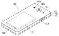
도 1a 내지 도 1b를 참조하면, 도 1a 및 1b는 본 발명과 관련된 이동 단말기의 일 예를 서로 다른 방향에서 바라본 개념도이다.Referring to FIGS. 1A and 1B, FIGS. 1A and 1B are conceptual diagrams illustrating mobile terminals according to the present invention in different directions.
도 1 a 및 1b를 참조하면, 개시된 이동 단말기(100)는 바 형태의 단말기 바디를 구비하고 있다. 다만, 본 발명은 여기에 한정되지 않고 와치 타입, 클립 타입, 글래스 타입 또는 2 이상의 바디들이 상대 이동 가능하게 결합되는 폴더 타입, 플립 타입, 슬라이드 타입, 스윙 타입, 스위블 타입 등 다양한 구조에 적용될 수 있다. 이동 단말기의 특정 유형에 관련될 것이나, 이동 단말기의 특정유형에 관한 설명은 다른 타입의 이동 단말기에 일반적으로 적용될 수 있다.Referring to FIGS. 1A and 1B, the disclosed
여기에서, 단말기 바디는 이동 단말기(100)를 적어도 하나의 집합체로 보아 이를 지칭하는 개념으로 이해될 수 있다.Here, the terminal body can be understood as a concept of referring to the
이동 단말기(100)는 외관을 이루는 케이스(예를 들면, 프레임, 하우징, 커버 등)를 포함한다. 도시된 바와 같이, 이동 단말기(100)는 프론트 케이스(101)와 리어 케이스(102)를 포함할 수 있다. 프론트 케이스(101)와 리어 케이스(102)의 결합에 의해 형성되는 내부공간에는 각종 전자부품들이 배치된다. 프론트 케이스(101)와 리어 케이스(102) 사이에는 적어도 하나의 미들 케이스가 추가로 배치될 수 있다.The
단말기 바디의 전면에는 디스플레이부(151)가 배치되어 정보를 출력할 수 있다. 도시된 바와 같이, 디스플레이부(151)의 윈도우(151a)는 프론트 케이스(101)에 장착되어 프론트 케이스(101)와 함께 단말기 바디의 전면을 형성할 수 있다.A
경우에 따라서, 리어 케이스(102)에도 전자부품이 장착될 수 있다. 리어 케이스(102)에 장착 가능한 전자부품은 착탈 가능한 배터리, 식별 모듈, 메모리 카드 등이 있다. 이 경우, 리어 케이스(102)에는 장착된 전자부품을 덮기 위한 후면커버(103)가 착탈 가능하게 결합될 수 있다. 따라서, 후면 커버(103)가 리어 케이스(102)로부터 분리되면, 리어 케이스(102)에 장착된 전자부품은 외부로 노출된다.In some cases, electronic components may also be mounted on the
도시된 바와 같이, 후면커버(103)가 리어 케이스(102)에 결합되면, 리어 케이스(102)의 측면 일부가 노출될 수 있다. 경우에 따라서, 상기 결합시 리어 케이스(102)는 후면커버(103)에 의해 완전히 가려질 수도 있다. 한편, 후면커버(103)에는 카메라(121b)나 음향 출력부(152b)를 외부로 노출시키기 위한 개구부가 구비될 수 있다.As shown, when the
이러한 케이스들(101, 102, 103)은 합성수지를 사출하여 형성되거나 금속, 예를 들어 스테인레스 스틸(STS), 알루미늄(Al), 티타늄(Ti) 등으로 형성될 수도 있다.These
이동 단말기(100)는, 복수의 케이스가 각종 전자부품들을 수용하는 내부 공간을 마련하는 위의 예와 달리, 하나의 케이스가 상기 내부 공간을 마련하도록 구성될 수도 있다. 이 경우, 합성수지 또는 금속이 측면에서 후면으로 이어지는 유니 바디의 이동 단말기(100)가 구현될 수 있다.The
한편, 이동 단말기(100)는 단말기 바디 내부로 물이 스며들지 않도록 하는 방수부(미도시)를 구비할 수 있다. 예를 들어, 방수부는 윈도우(151a)와 프론트 케이스(101) 사이, 프론트 케이스(101)와 리어 케이스(102) 사이 또는 리어 케이스(102)와 후면 커버(103) 사이에 구비되어, 이들의 결합 시 내부 공간을 밀폐하는 방수부재를 포함할 수 있다.Meanwhile, the
이동 단말기(100)에는 디스플레이부(151), 제1 및 제2 음향 출력부(152a, 152b), 근접 센서(141), 조도 센서(142), 광 출력부(154), 제1 및 제2 카메라(121a, 121b), 제1 및 제2 조작유닛(123a, 123b), 마이크로폰(122), 인터페이스부(160) 등이 구비될 수 있다.The
이하에서는, 도 1a 및 도 1b에 도시된 바와 같이, 단말기 바디의 전면에 디스플레이부(151), 제1 음향 출력부(152a), 근접 센서(141), 조도 센서(142), 광 출력부(154), 제1 카메라(121a) 및 제1 조작유닛(123a)이 배치되고, 단말기 바디의 측면에 제2 조작유닛(123b), 마이크로폰(122) 및 인터페이스부(160)이 배치되며, 단말기 바디의 후면에 제2 음향 출력부(152b) 및 제2 카메라(121b)가 배치된 이동 단말기(100)를 일 예로 들어 설명한다.1A and 1B, a
다만, 이들 구성은 이러한 배치에 한정되는 것은 아니다. 이들 구성은 필요에 따라 제외 또는 대체되거나, 다른 면에 배치될 수 있다. 예를 들어, 단말기 바디의 전면에는 제1 조작유닛(123a)이 구비되지 않을 수 있으며, 제2 음향 출력부(152b)는 단말기 바디의 후면이 아닌 단말기 바디의 측면에 구비될 수 있다.However, these configurations are not limited to this arrangement. These configurations may be excluded or replaced as needed, or placed on different planes. For example, the
디스플레이부(151)는 이동 단말기(100)에서 처리되는 정보를 표시(출력)한다. 예를 들어, 디스플레이부(151)는 이동 단말기(100)에서 구동되는 응용 프로그램의 실행화면 정보, 또는 이러한 실행화면 정보에 따른 UI(User Interface), GUI(Graphic User Interface) 정보를 표시할 수 있다.The
디스플레이부(151)는 액정 디스플레이(liquid crystal display, LCD), 박막 트랜지스터 액정 디스플레이(thin film transistor-liquid crystal display, TFT LCD), 유기 발광 다이오드(organic light-emitting diode, OLED), 플렉서블 디스플레이(flexible display), 3차원 디스플레이(3D display), 전자잉크 디스플레이(e-ink display) 중에서 적어도 하나를 포함할 수 있다.The
또한, 디스플레이부(151)는 이동 단말기(100)의 구현 형태에 따라 2개 이상 존재할 수 있다. 이 경우, 이동 단말기(100)에는 복수의 디스플레이부들이 하나의 면에 이격되거나 일체로 배치될 수 있고, 또한 서로 다른 면에 각각 배치될 수도 있다.In addition, the
디스플레이부(151)는 터치 방식에 의하여 제어 명령을 입력 받을 수 있도록, 디스플레이부(151)에 대한 터치를 감지하는 터치센서를 포함할 수 있다. 이를 이용하여, 디스플레이부(151)에 대하여 터치가 이루어지면, 터치센서는 상기 터치를 감지하고, 제어부(180)는 이에 근거하여 상기 터치에 대응하는 제어명령을 발생시키도록 이루어질 수 있다. 터치 방식에 의하여 입력되는 내용은 문자 또는 숫자이거나, 각종 모드에서의 지시 또는 지정 가능한 메뉴항목 등일 수 있다.The
한편, 터치센서는, 터치패턴을 구비하는 필름 형태로 구성되어 윈도우(151a)와 윈도우(151a)의 배면 상의 디스플레이(미도시) 사이에 배치되거나, 윈도우(151a)의 배면에 직접 패터닝되는 메탈 와이어가 될 수도 있다. 또는, 터치센서는 디스플레이와 일체로 형성될 수 있다. 예를 들어, 터치센서는, 디스플레이의 기판 상에 배치되거나, 디스플레이의 내부에 구비될 수 있다.The touch sensor may be a film having a touch pattern and disposed between the
이처럼, 디스플레이부(151)는 터치센서와 함께 터치 스크린을 형성할 수 있으며, 이 경우에 터치 스크린은 사용자 입력부(123, 도 1a 참조)로 기능할 수 있다. 경우에 따라, 터치 스크린은 제1조작유닛(123a)의 적어도 일부 기능을 대체할 수 있다.In this way, the
제1 음향 출력부(152a)는 통화음을 사용자의 귀에 전달시키는 리시버(receiver)로 구현될 수 있으며, 제2 음향 출력부(152b)는 각종 알람음이나 멀티미디어의 재생음을 출력하는 라우드 스피커(loud speaker)의 형태로 구현될 수 있다.The first
디스플레이부(151)의 윈도우(151a)에는 제1 음향 출력부(152a)로부터 발생되는 사운드의 방출을 위한 음향홀이 형성될 수 있다. 다만, 본 발명은 이에 한정되는 것은 아니고, 상기 사운드는 구조물 간의 조립틈(예를 들어, 윈도우(151a)와 프론트 케이스(101) 간의 틈)을 따라 방출되도록 구성될 수 있다. 이 경우, 외관상 음향 출력을 위하여 독립적으로 형성되는 홀이 보이지 않거나 숨겨져 이동 단말기(100)의 외관이 보다 심플해질 수 있다.The
광 출력부(154)는 이벤트의 발생시 이를 알리기 위한 빛을 출력하도록 이루어진다. 상기 이벤트의 예로는 메시지 수신, 호 신호 수신, 부재중 전화, 알람, 일정 알림, 이메일 수신, 애플리케이션을 통한 정보 수신 등을 들 수 있다. 제어부(180)는 사용자의 이벤트 확인이 감지되면, 빛의 출력이 종료되도록 광 출력부(154)를 제어할 수 있다.The
제1 카메라(121a)는 촬영 모드 또는 화상통화 모드에서 이미지 센서에 의해 얻어지는 정지영상 또는 동영상의 화상 프레임을 처리한다. 처리된 화상 프레임은 디스플레이부(151)에 표시될 수 있으며, 메모리(170)에 저장될 수 있다.The
제1 및 제2 조작유닛(123a, 123b)은 이동 단말기(100)의 동작을 제어하기 위한 명령을 입력 받기 위해 조작되는 사용자 입력부(123)의 일 예로서, 조작부(manipulating portion)로도 통칭될 수 있다. 제1 및 제2 조작유닛(123a, 123b)은 터치, 푸시, 스크롤 등 사용자가 촉각적인 느낌을 받으면서 조작하게 되는 방식(tactile manner)이라면 어떤 방식이든 채용될 수 있다. 또한, 제1 및 제2 조작유닛(123a, 123b)은 근접 터치(proximity touch), 호버링(hovering) 터치 등을 통해서 사용자의 촉각적인 느낌이 없이 조작하게 되는 방식으로도 채용될 수 있다.The first and
본 도면에서는 제1 조작유닛(123a)이 터치키(touch key)인 것으로 예시하나, 본 발명이 이에 한정되는 것은 아니다. 예를 들어, 제1 조작유닛(123a)은 푸시키(mechanical key)가 되거나, 터치키와 푸시키의 조합으로 구성될 수 있다.In this figure, the
제1 및 제2 조작유닛(123a, 123b)에 의하여 입력되는 내용은 다양하게 설정될 수 있다. 예를 들어, 제1 조작유닛(123a)은 메뉴, 홈키, 취소, 검색 등의 명령을 입력 받고, 제2 조작유닛(123b)은 제1 또는 제2 음향 출력부(152a, 152b)에서 출력되는 음향의 크기 조절, 디스플레이부(151)의 터치 인식 모드로의 전환 등의 명령을 입력 받을 수 있다.The contents input by the first and
한편, 단말기 바디의 후면에는 사용자 입력부(123)의 다른 일 예로서, 후면 입력부(미도시)가 구비될 수 있다. 이러한 후면 입력부는 이동 단말기(100)의 동작을 제어하기 위한 명령을 입력 받기 위해 조작되는 것으로서, 입력되는 내용은 다양하게 설정될 수 있다. 예를 들어, 전원의 온/오프, 시작, 종료, 스크롤 등과 같은 명령, 제1 및 제2 음향 출력부(152a, 152b)에서 출력되는 음향의 크기 조절, 디스플레이부(151)의 터치 인식 모드로의 전환 등과 같은 명령을 입력 받을 수 있다. 후면 입력부는 터치입력, 푸시입력 또는 이들의 조합에 의한 입력이 가능한 형태로 구현될 수 있다.On the other hand, a rear input unit (not shown) may be provided on the rear surface of the terminal body as another example of the
후면 입력부는 단말기 바디의 두께방향으로 전면의 디스플레이부(151)와 중첩되게 배치될 수 있다. 일 예로, 사용자가 단말기 바디를 한 손으로 쥐었을 때 검지를 이용하여 용이하게 조작 가능하도록, 후면 입력부는 단말기 바디의 후면 상단부에 배치될 수 있다. 다만, 본 발명은 반드시 이에 한정되는 것은 아니며, 후면 입력부의 위치는 변경될 수 있다.The rear input unit may be disposed so as to overlap with the
이처럼 단말기 바디의 후면에 후면 입력부가 구비되는 경우, 이를 이용한 새로운 형태의 유저 인터페이스가 구현될 수 있다. 또한, 앞서 설명한 터치 스크린 또는 후면 입력부가 단말기 바디의 전면에 구비되는 제1 조작유닛(123a)의 적어도 일부 기능을 대체하여, 단말기 바디의 전면에 제1 조작유닛(123a)이 미배치되는 경우, 디스플레이부(151)가 보다 대화면(大畵面)으로 구성될 수 있다.When a rear input unit is provided on the rear surface of the terminal body, a new type of user interface using the rear input unit can be realized. When the
한편, 이동 단말기(100)에는 사용자의 지문을 인식하는 지문인식센서가 구비될 수 있으며, 제어부(180)는 지문인식센서를 통하여 감지되는 지문정보를 인증수단으로 이용할 수 있다. 상기 지문인식센서는 디스플레이부(151) 또는 사용자 입력부(123)에 내장될 수 있다.Meanwhile, the
마이크로폰(122)은 사용자의 음성, 기타 소리 등을 입력 받도록 이루어진다. 마이크로폰(122)은 복수의 개소에 구비되어 스테레오 음향을 입력 받도록 구성될 수 있다.The
인터페이스부(160)는 이동 단말기(100)를 외부기기와 연결시킬 수 있는 통로가 된다. 예를 들어, 인터페이스부(160)는 다른 장치(예를 들어, 이어폰, 외장 스피커)와의 연결을 위한 접속단자, 근거리 통신을 위한 포트[예를 들어, 적외선 포트(IrDA Port), 블루투스 포트(Bluetooth Port), 무선 랜 포트(Wireless LAN Port) 등], 또는 이동 단말기(100)에 전원을 공급하기 위한 전원공급단자 중 적어도 하나일 수 있다. 이러한 인터페이스부(160)는 SIM(Subscriber Identification Module) 또는 UIM(User Identity Module), 정보 저장을 위한 메모리 카드 등의 외장형 카드를 수용하는 소켓의 형태로 구현될 수도 있다.The
단말기 바디의 후면에는 제2카메라(121b)가 배치될 수 있다. 이 경우, 제2카메라(121b)는 제1카메라(121a)와 실질적으로 반대되는 촬영 방향을 가지게 된다.And a
제2카메라(121b)는 적어도 하나의 라인을 따라 배열되는 복수의 렌즈를 포함할 수 있다. 복수의 렌즈는 행렬(matrix) 형식으로 배열될 수도 있다. 이러한 카메라는, (camera array) 카메라 어레이로 명명될 수 있다. 제2카메라(121b)가 어레이 카메라로 구성되는 경우, 복수의 렌즈를 이용하여 다양한 방식으로 영상을 촬영할 수 있으며, 보다 나은 품질의 영상을 획득할 수 있다.The
플래시(124)는 제2카메라(121b)에 인접하게 배치될 수 있다. 플래시(124)는 제2카메라(121b)로 피사체를 촬영하는 경우에 피사체를 향하여 빛을 비추게 된다.The
단말기 바디에는 제2 음향 출력부(152b)가 추가로 배치될 수 있다. 제2 음향 출력부(152b)는 제1 음향 출력부(152a)와 함께 스테레오 기능을 구현할 수 있으며, 통화시 스피커폰 모드의 구현을 위하여 사용될 수도 있다.And a second
단말기 바디에는 무선 통신을 위한 적어도 하나의 안테나가 구비될 수 있다. 안테나는 단말기 바디에 내장되거나, 케이스에 형성될 수 있다. 예를 들어, 방송 수신 모듈(111, 도 1a 참조)의 일부를 이루는 안테나는 단말기 바디에서 인출 가능하게 구성될 수 있다. 또는, 안테나는 필름 타입으로 형성되어 후면 커버(103)의 내측면에 부착될 수도 있고, 도전성 재질을 포함하는 케이스가 안테나로서 기능하도록 구성될 수도 있다.The terminal body may be provided with at least one antenna for wireless communication. The antenna may be embedded in the terminal body or formed in the case. For example, an antenna constituting a part of the broadcast receiving module 111 (see FIG. 1A) may be configured to be able to be drawn out from the terminal body. Alternatively, the antenna may be formed in a film type and attached to the inner surface of the
단말기 바디에는 이동 단말기(100)에 전원을 공급하기 위한 전원 공급부(190, 도 1a 참조)가 구비된다. 전원 공급부(190)는 단말기 바디에 내장되거나, 단말기 바디의 외부에서 착탈 가능하게 구성되는 배터리(191)를 포함할 수 있다.The terminal body is provided with a power supply unit 190 (see FIG. 1A) for supplying power to the
배터리(191)는 인터페이스부(160)에 연결되는 전원 케이블을 통하여 전원을 공급받도록 구성될 수 있다. 또한, 배터리(191)는 무선충전기기를 통하여 무선충전 가능하도록 구성될 수도 있다. 상기 무선충전은 자기유도방식 또는 공진방식(자기공명방식)에 의하여 구현될 수 있다.The
한편, 본 도면에서는 후면 커버(103)가 배터리(191)를 덮도록 리어 케이스(102)에 결합되어 배터리(191)의 이탈을 제한하고, 배터리(191)를 외부 충격과 이물질로부터 보호하도록 구성된 것을 예시하고 있다. 배터리(191)가 단말기 바디에 착탈 가능하게 구성되는 경우, 후면 커버(103)는 리어 케이스(102)에 착탈 가능하게 결합될 수 있다.The
이동 단말기(100)에는 외관을 보호하거나, 이동 단말기(100)의 기능을 보조 또는 확장시키는 액세서리가 추가될 수 있다. 이러한 액세서리의 일 예로, 이동 단말기(100)의 적어도 일면을 덮거나 수용하는 커버 또는 파우치를 들 수 있다. 커버 또는 파우치는 디스플레이부(151)와 연동되어 이동 단말기(100)의 기능을 확장시키도록 구성될 수 있다. 액세서리의 다른 일 예로, 터치 스크린에 대한 터치입력을 보조 또는 확장하기 위한 터치펜을 들 수 있다.The
한편, 본 발명에서는 이동 단말기에서 처리되는 정보를 플렉서블 디스플레이(flexible display)를 이용하여 표시할 수 있다. 이하, 첨부된 도면을 바탕으로 이에 대하여 보다 구체적으로 살펴본다.Meanwhile, in the present invention, information processed in the mobile terminal can be displayed using a flexible display. Hereinafter, the present invention will be described in detail with reference to the accompanying drawings.
도 2는 본 발명에 따른 변형 가능한 이동 단말기(200)의 다른 예를 설명하기 위한 개념도이다.2 is a conceptual diagram for explaining another example of the
도시된 바와 같이, 디스플레이부(251)는 외력에 의하여 변형 가능하게 구성될 수 있다. 상기 변형은 디스플레이부(251)의 휘어짐, 구부러짐, 접힘, 비틀림, 말림 중 적어도 하나일 수 있다. 이러한 변형 가능한 디스플레이부(251)는 플렉서블 디스플레이부로 명명될 수 있다. 여기에서, 플렉서블 디스플레이부(251)는 일반적인 플렉서블 디스플레이와 전자 종이(e-paper) 및 그 조합을 모두 포함할 수 있다. 일반적으로 이동 단말기(200)는 도1a 또는 도 1b의 이동 단말기(100)의 특징 또는 그와 유사한 특징을 포함할 수 있다.As shown, the
일반적인 플렉서블 디스플레이는 기존의 평판 디스플레이의 특성을 유지하면서, 종이와 같이 휘어짐, 구부러짐, 접힘, 비틀림 또는 말림이 가능한 얇고 유연한 기판 위에 제작되어, 가볍고 쉽게 깨지지 않는 튼튼한 디스플레이를 말한다.A typical flexible display refers to a sturdy display that is lightweight and does not break easily, such as paper, formed on a thin, flexible substrate that can flex, bend, fold, twist, or curl like a conventional flat panel display.
또한, 전자 종이는 일반적인 잉크의 특징을 적용한 디스플레이 기술로서, 반사광을 사용하는 점이 기존의 평판 디스플레이와 다른 점일 수 있다. 전자 종이는 트위스트 볼을 이용하거나, 캡슐을 이용한 전기영동(電氣泳動, electrophoresis)을 이용하여, 정보를 변경할 수 있다.In addition, the electronic paper is a display technology to which general ink characteristics are applied, and the point that the reflected light is used is different from the conventional flat panel display. The electronic paper can be changed by using a twist ball or electrophoresis (electrophoresis) using a capsule.
플렉서블 디스플레이부(251)가 변형되지 않는 상태(예를 들어, 무한대의 곡률반경을 가지는 상태, 이하 제1 상태라 한다)에서, 플렉서블 디스플레이부(251)의 디스플레이 영역은 평면이 된다. 상기 제1 상태에서 외력에 의하여 변형된 상태(예를 들어, 유한의 곡률반경을 가지는 상태, 이하, 제2 상태라 한다)에서는 상기 디스플레이 영역이 곡면이 될 수 있다. 도시된 바와 같이, 상기 제2 상태에서 표시되는 정보는 곡면상에 출력되는 시각 정보가 될 수 있다. 이러한 시각 정보는 매트릭스 형태로 배치되는 단위 화소(sub-pixel)의 발광이 독자적으로 제어됨에 의하여 구현된다. 상기 단위 화소는 하나의 색을 구현하기 위한 최소 단위를 의미한다.In a state in which the
플렉서블 디스플레이부(251)는 상기 제1 상태에서 평평한 상태가 아닌, 휘어진 상태(예를 들어, 상하 또는 좌우로 휘어진 상태)에 놓일 수 있다. 이 경우, 플렉서블 디스플레이부(251)에 외력이 가해지면, 플렉서블 디스플레이부(251)는 평평한 상태(혹은 보다 덜 휘어진 상태) 또는 보다 많이 휘어진 상태로 변형될 수 있다.The
한편, 플렉서블 디스플레이부(251)는 터치센서와 조합되어 플렉서블 터치 스크린을 구현할 수 있다. 플렉서블 터치 스크린에 대하여 터치가 이루어지면, 제어부(180, 도 22 참조)는 이러한 터치입력에 상응하는 제어를 수행할 수 있다. 플렉서블 터치 스크린은 상기 제1 상태뿐만 아니라 상기 제2 상태에서도 터치입력을 감지하도록 이루어질 수 있다.Meanwhile, the
한편, 본 변형 예에 따른 이동 단말기(200)에는 플렉서블 디스플레이부(251)의 변형을 감지할 수 있는 변형감지수단이 구비될 수 있다. 이러한 변형감지수단은 센싱부(140, 도 22 참조)에 포함될 수 있다.Meanwhile, the
상기 변형감지수단은 플렉서블 디스플레이부(251) 또는 케이스(201)에 구비되어, 플렉서블 디스플레이부(251)의 변형과 관련된 정보를 감지할 수 있다. 여기에서, 변형과 관련된 정보는, 플렉서블 디스플레이부(251)가 변형된 방향, 변형된 정도, 변형된 위치, 변형된 시간 및 변형된 플렉서블 디스플레이부(251)가 복원되는 가속도 등이 될 수 있으며, 이 밖에도 플렉서블 디스플레이부(251)의 휘어짐으로 인하여 감지 가능한 다양한 정보일 수 있다.The deformation detecting unit may be provided in the
또한, 제어부(180)는 상기 변형감지수단에 의하여 감지되는 플렉서블 디스플레이부(251)의 변형과 관련된 정보에 근거하여, 플렉서블 디스플레이부(251) 상에 표시되는 정보를 변경하거나, 이동 단말기(200)의 기능을 제어하기 위한 제어신호를 생성할 수 있다.The
한편, 본 변형 예에 따른 이동 단말기(200)는 플렉서블 디스플레이부(251)를 수용하는 케이스(201)를 포함할 수 있다. 케이스(201)는 플렉서블 디스플레이부(251)의 특성을 고려하여, 외력에 의하여 플렉서블 디스플레이부(251)와 함께 변형 가능하도록 구성될 수 있다.Meanwhile, the
아울러, 이동 단말기(200)에 구비되는 배터리(미도시) 또한 플렉서블 디스플레이부(251)의 특성을 고려하여, 외력에 의하여 플렉서블 디스플레이부(251)와 함께 변형 가능하도록 구성될 수 있다. 상기 배터리를 구현하기 위하여, 배터리 셀을 위로 쌓은 스택앤폴딩(stack and folding) 방식이 적용될 수 있다.In addition, the battery (not shown) included in the
플렉서블 디스플레이부(251)의 상태 변형은 외력에 의한 것으로만 국한되지는 않는다. 예를 들어, 플렉서블 디스플레이부(251)가 제 1 상태를 가지고 있을 때, 사용자 혹은 애플리케이션의 명령에 의해서, 제 2 상태로 변형될 수도 있다.The state change of the
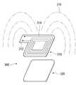
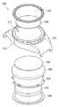
도 3은 본 발명과 관련된 근거리 통신용 안테나의 구성 및 동작의 일 예를 나타낸다. 도 3은 근거리 통신용 안테나(310), 그리고 차폐막(320)을 나타낸다.3 shows an example of the configuration and operation of an antenna for a short-range communication according to the present invention. 3 shows an
근거리 통신용 안테나(310)는 보드(312)와, 보드(312)상에 배치되는 전선(314)을 포함할 수 있다. 근거리 통신용 안테나(310)는, 예를 들어, NFC안테나가 될 수 있다. 보드(312)는 플렉시블한 소재가 될 수 있고, 하드한 소재가 될 수도 있다. 보드(312)가 플렉시블한 소재로 형성되는 경우, 보드(312)는 필름의 형태가 될 수 있다. 전선(314)은 보드(312) 상에 배치될 수 있다. 예를 들면, 근거리 통신용 안테나(310)는 FPCB가 될 수 있다. 이때, 전선(314)은 보드(312) 상에 권선을 형성할 수 있다. 권선은 1회가 될 수 있고, 그 보다 많은 수가 될 수 도 있다.The short-
차폐막(320)은, 근거리 통신용 안테나(312)에서 형성되는 전자기장(316)이 외부로부터 받는 영향을 최소화할 수 있도록, 전자기파 차단재로 형성될 수 있다. 예를 들면, 차폐막(320)은 ferrite sheet가 될 수 있다.The
근거리 통신용 안테나(310)에 전자기장(316)이 형성되면 전선(314)에 전류가 흐를 수 있다. 반대로 전선(314)에 전류가 흐르면 근거리 통신용 안테나(310)에 전자기장(316)이 형성될 수 있다. 이를 이용하여, 이동 단말기는 외부 단말기와 신호를 송수신할 수 있다. 이때, 차폐막(320)은 근거리 통신용 안테나(310)를 중심으로 외부 단말기의 반대측에 위치하여, 노이즈 억제 및 첨예도(quality fator: 또는 선택도) 등을 향상시킬 수 있다.When the
이하에서, 안테나(300)는 근거리 통신용 안테나(310)와 차폐막(320)을 포함하는 의미로 한다.Hereinafter, the
도 4는 본 발명의 실시예에 따른 이동 단말기의 일 예를 나타낸다. 도 4는 프레임(420), 디스플레이패널(430), 그리고 안테나(300)를 나타낸다.4 shows an example of a mobile terminal according to an embodiment of the present invention. FIG. 4 shows a
프레임(420)은 이동 단말기의 프레임일 수 있고, 디스플레이패널(430)의 프레임일 수도 있다. 프레임(420)은 전자부품을 적정위치에 고정시키기 위한 것으로, 이러한 의미로 해석될 수 있다면 앞서 언급한 것에 한정되지 않는다. 프레임(420)은 합성수지로 형성될 수 있고, 금속으로 형성될 수도 있다. 프레임(420)은 함몰부(422)를 포함할 수 있다. 함몰부(422)는 프레임(420)의 일측에 형성될 수 있다. 함몰부(422)는, 포트레이트뷰를 기준으로, 디스플레이패널(430)의 상측, 즉 프레임(420)의 상측에 형성될 수 있다. 이에 따라, 사용자가 이동 단말기를, 일반적으로 파지한 상태에서 편하게, 태깅(tagging)을 할 수 있다.The
디스플레이패널(430)은 LCD패널이 될 수 있고, OLED패널이 될 수도 있다. 디스플레이패널(430)은 이에 한정되지 않을 수 있다.The
안테나(300)는 프레임(420)과 디스플레이패널(430) 사이에 위치한다. 더불어, 안테나(300)는 프레임(420)에 형성된 함몰부(422)에 안착될 수 있다. 이는, 이동 단말기가 요구되는 강성을 유지할 뿐만 아니라 슬림한 두께를 지니기 위한 것으로 이해될 수 있다.The
도 5는 본 발명의 실시예에 따른 이동 단말기의 일 예를 나타낸다. 도 5는 디스플레이패널(430), 안테나(300), 그리고 FPCB(440)를 나타낸다.5 illustrates an example of a mobile terminal according to an embodiment of the present invention. 5 shows a
FPCB(440)는 디스플레이패널(430)과 전기적으로 연결될 수 있다. FPCB(440)는 디스플레이패널(430)에 이미지정보를 송수신하기 위한 것으로 이해될 수 있다. 따라서, 동일한 기능을 수행하는 것이면, FPCB에 한정되지 않는다.The
안테나(300)는 FPCB(440)상에 위치할 수 있다. 이는, 안테나(300)가 FPCB(440)와 동일면을 공유하는 것을 의미할 수 있다. 예를 들면, 안테나(300)는 FPCB(440)에 일체로 형성될 수 있음을 의미한다. 이 경우, 안테나(300)는 FPCB(440)와 커넥터(450)를 공유할 수 있다. 다른 관점에서, 안테나(300)는 FPCB(440)와 전기적으로 절연될 수 있음을 의미한다. 이에 따라, 조립공정이 단순해질 수 있다.The
도 6은 본 발명의 실시예에 따른 이동 단말기의 일 예를 나타낸다. 도 6은, 디스플레이패널(430), 안테나(300), 그리고 FPCB(440)를 나타낸다.6 shows an example of a mobile terminal according to an embodiment of the present invention. 6 shows the
안테나(300)는 FPCB(440)와 분리되어 형성될 수 있다. 이 경우, 안테나(300)와 FPCB(440)는 각각의 커넥터(452,454)를 구비할 수 있다. 각각의 커넥터(452,454)가 후술하는 제어부에 전기적으로 연결되는 방법은 다양할 수 있다. 이에 따라, 안테나(300)와 FPCB(440) 중 어느 하나가 수리를 요할 경우, 수리비용이 절감될 수 있다.The
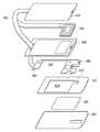
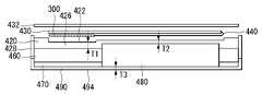
도 7은 본 발명의 실시예에 따른 이동 단말기의 일 예를 나타낸다. 도 7은, 디스플레이패널(430), 안테나(300), FPCB(440), 프레임(420), PCB(460), 백커버(470), 배터리(480), 그리고 배터리커버(490)를 나타낸다.7 shows an example of a mobile terminal according to an embodiment of the present invention. 7 shows a
앞서 설명된 내용은 동일한 참조부호를 붙이고, 설명을 생략한다. PCB(460)는 적어도 하나의 전자소자를 구비한다. 단말기의 동작을 위한 센서, 입력부, 제어부 등은 전자소자에 실장될 수 있다. 전자소자는 복수개가 실장될 수 있고, 하나로 집적화되어 실장될 수도 있다. 전자소자는, 앞서 설명한 FPCB(440)를 제어부에 전기적으로 연결될 수 있는 커넥터(462)가 될 수 있다. 이동 단말기가 슬림한 두께를 지닐 수 있도록, PCB(460)는 배터리(480)가 노출되는 영역(464)을 구비할 수 있다. 배터리(480)는 이동 단말기의 부품들 중 두께가 가장 두꺼운 것일 수 있다.The same components as those described above are denoted by the same reference numerals, and a description thereof will be omitted. The
FPCB(440)는 전자소자에 전기적으로 연결될 수 있다. 이 때, FPCB(440)는 프레임(420)의 면을 관통하여 전자소자에 연결될 수 있다.The
백커버(470)는 PCB(460)를 프레임(420)에 고정시킬 수 있다. 백커버(470)는, 프레임(420)과 대응될 뿐만 아니라 PCB(460)와 대응되도록, 형성될 수 있다. 백커버(470)는 나사결합에 의해 프레임(420)에 고정될 수 있다. 백커버(470)는 PCB(460)의 일부가 노출되는 영역(472)을 구비할 수 있다. 또한, 이동 단말기가 슬림한 두께를 지닐 수 있도록, 백커버(470)는 배터리(480)가 노출되는 영역(474)을 구비할 수 있다. 이동 단말기는, PCB(460) 및 백커버(470)에 구비된 배터리(480)가 노출되는 영역(464,474)에 의해 결과적으로 배터리 수용부(464 및 474)가 형성될 수 있다.The
배터리(480)는 이동 단말기에 전원을 공급하기 위한 것으로, 2차 전지가 될 수 있다. 배터리는 배터리 수용부(464 및 474)에 안착될 수 있다. 배터리커버(490)는 백커버(470)의 후면 및 배터리(480)를 동시에 덮으며, 이동 단말기에 고정될 수 있다. 즉, 배터리커버(490)는 이동 단말기의 외장을 형성할 수 있음을 의미한다. 배터리커버(490)는, 금속으로 형성될 수 있고, 합성수지로 형성될 수도 있다. 배터리커버(490)가 금속으로 형성되는 경우, 이동 단말기의 내구성을 향상시킬 수 있을 뿐만 아니라 외관이 수려해질 수도 있다.The
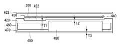
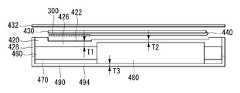
도 8은 본 발명의 실시예에 따른 이동 단말기의 일 예를 나타낸다. 도 8은 이동 단말기의 단면을 보여주기 위한 선(A-A')을 나타낸다. 도 9는 도8에 따른 이동 단말기의 단면의 일 예를 나타낸다.FIG. 8 shows an example of a mobile terminal according to an embodiment of the present invention. 8 shows a line (A-A ') for showing a cross section of the mobile terminal. FIG. 9 shows an example of a cross section of the mobile terminal according to FIG.
도 9는 터치윈도우(432), 디스플레이패널(430), 안테나(300), FPCB(440), 프레임(420), 함몰부(422), PCB(460), 배터리(480), 백커버(470), 그리고 배터리커버(490)를 나타낸다. 한편, 프레임(420), 백커버(470) 및 배터리커버(490)가 합성수지로 형성될 수 있다.9 shows the
프레임(420)은, 이동 단말기에 외력이 가해질 때, 일정수준의 내구성이 보장되도록 형성될 수 있다. 이를 위해, 프레임(420)은 일정수준의 두께(T1, T2)를 지니도록 형성될 수 있다. 이는, 프레임(420)이 일정수준의 두께(T1, T2) 이하로 형성되는 경우, 이동 단말기가 쉽게 파손될 수 있음을 의미한다. 따라서, 프레임(420)의 두께(T1, T2)는, 일정수준 이하로 형성되면, 이동 단말기의 내구성이 낮아지는 것으로 이해될 수 있다. 함몰부(422)가 T2영역 외에 위치하면 이동 단말기의 내구성은 일정수준 보장될 수 있다. 프레임(420)은, 슬림한 두께(T1, T2)를 지닐 뿐만 아니라 향상된 내구성을 위해, 금속으로 형성될 수 있다.The
베터리커버(490)는, 주로 이동 단말기의 외관을 형성하는 것으로, 그 두께(T3)를 일정수준이하로 형성할 수 있다. 이는, 배터리커버(490)가, 종래, 근거리 통신을 위한 안테나를 구비하여 그 두께를 일정수준 이하로 줄일 수 없는 한계가 있는 것과, 차이가 있다. 배터리커버(490)는, 슬림한 두께(T3)를 지닐 뿐만 아니라 향상된 내구성을 위해, 금속으로 형성될 수 있다.The
함몰부(422)는, 프레임(420)을 중심으로, 배터리(480)가 수용되는 위치와 다를 수 있다. 이는, 함몰부(422)가 T2영역 외에 위치하는 것으로 이해될 수 있다. 이에 따라, 프레임(420)은 이동 단말기의 내구성을 위해 요구되는 수준의 두께(T1,T2)를 가질 수 있다. 안테나(300)가 함물부(422)에 안착됨은 앞서 설명하였다. 이러한 구성을 통해, 이동 단말기는 보다 슬림한 두께를 가질 수 있다.The
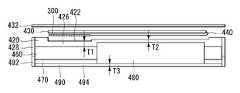
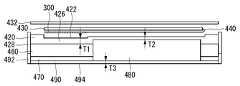
도 10은 터치윈도우(432), 디스플레이패널(430), 안테나(300), FPCB(440), 프레임(420), 함몰부(422), PCB(460), 배터리(480), 백커버(470), 그리고 배터리커버(490)를 나타낸다. 도 10은 프레임(420)의 내부(426)는 합성수지로 형성되고, 프레임(420)의 외부(428)는 금속으로 형성되고, 배터리커버(490)는 금속으로 형성됨을 나타낸다.10 is a perspective view showing a
함몰부(422)는, 프레임(420)을 중심으로, 배터리(480)가 수용되는 위치와 다를 수 있다. 이는, 함몰부(422)가 T2영역 외에 위치하는 것으로 이해될 수 있다. 이에 따라, 프레임(420)은 이동 단말기의 내구성을 위해 요구되는 수준의 두께(T1,T2)를 가질 수 있다. 안테나(300)가 함물부(422)에 안착됨은 앞서 설명하였다. 이러한 구성을 통해, 이동 단말기는 보다 슬림한 두께를 가질 수 있다.The
또한, 프레임(420)의 외부(428) 및 배터리커버(490)가 금속으로 형성되는 경우, 안테나(300)는 금속과 반대방향으로 방사를 하여 성능을 발휘할 수 있다. 안테나(300)가 금속으로부터 받는 영향은, 도 3을 참조하여, 차폐막(320:ferrite sheet)를 설명하면서 이미 언급되었다. 안테나(300)가 디스플레이패널(430)과 프레임(420) 사이에 위치할 때, 이동 단말기가 근거리 통신을 통해 정보를 방해 없이 수집 전달할 수 있다. 다른 측면에서, 안테나(300)가 디스플레이패널(430)과 프레임(420) 사이에 위치할 때, 안테나(300)가, 이동 단말기에 구비된 전자부품들 또는 금속에 의한, 전자기파의 간섭 없이 기능할 수 있다.In addition, when the
도 11은 터치윈도우(432), 디스플레이패널(430), 안테나(300), FPCB(440), 프레임(420), 함몰부(422), PCB(460), 배터리(480), 백커버(470), 그리고 배터리커버(490)를 나타낸다. 도 11은 프레임(420)의 내부(426)는 합성수지로 형성되고, 프레임(420)의 외부(428)는 금속으로 형성되고, 배터리커버(490)의 일부(492)는 금속으로, 다른 부분(494)은 합성수지로 형성됨을 나타낸다.11 illustrates a
함몰부(422)는, 프레임(420)을 중심으로, 배터리(480)가 수용되는 위치와 다를 수 있다. 이는, 함몰부(422)가 T2영역 외에 위치하는 것으로 이해될 수 있다. 이에 따라, 프레임(420)은 이동 단말기의 내구성을 위해 요구되는 수준의 두께(T1,T2)를 가질 수 있다. 안테나(300)가 함물부(422)에 안착됨은 앞서 설명하였다. 이러한 구성을 통해, 이동 단말기는 보다 슬림한 두께를 가질 수 있다.The
도 9 내지 11을 참조하여, 설명된 프레임(420), 백커버(470), 그리고 배터리커버(490)는 일체로 형성될 수도 있다.9 to 11, the
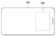
도 12는 본 발명의 실시예에 따른 이동 단말기의 전면의 일 예를 나타낸다. 도 12는 디스플레이패널(430), 그리고 안테나(300)를 나타낸다. 안테나(300)는, 디스플레이패널(430)이 포트레이트뷰일 때, 상측에 위치할 수 있다. 이러한 위치에 의해, 사용자가 근거리 통신을 시도할 때, 사용자가, 일반적으로 이동 단말기 파지의 경우, 편하게 태깅(tagging)을 할 수 있다.12 shows an example of a front surface of a mobile terminal according to an embodiment of the present invention. 12 shows a
도 13 및 14는 본 발명에 따른 이동 단말기의 전면의 다른 예들을 나타낸다. 도 13 및 14는 디스플레이패널(430), 그리고 안테나(300)를 나타낸다. 안테나(300)는, 디스플레이패널(430)의 둘레에 위치할 수 있다. 이러한 위치에 의해, 사용자가 근거리 통신을 시도할 때, 사용자가 태깅(tagging) 성공률을 높일 수 있다. 다른 측면에서, 이러한 위치는 안테나(300)의 방사성능을 향상시킬 수 있음을 의미할 수 있다.13 and 14 show other examples of the front face of the mobile terminal according to the present invention. Figs. 13 and 14 show the
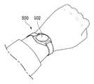
도 15 및 16은 본 발명의 실시예에 따른 웨어러블 디바이스의 일 예를 나타내고, 도 17은 본 발명의 실시예에 따른 웨어러블 디바이스의 단면의 일예를 나타낸다. 웨어러블 디바이스(500)는 이동 단말기의 한 종류로서, 사용자의 신체에 착용하는 이동 단말기이다. 웨어러블 디바이스(500)는 전술 또는 후술되는 이동 단말기의 구성 중 일부 또는 전부를 포함할 수 있다. 동일한 설명은 동일한 참조부호를 붙이고 생략한다.FIGS. 15 and 16 show an example of a wearable device according to an embodiment of the present invention, and FIG. 17 shows an example of a section of a wearable device according to an embodiment of the present invention. The
도 15 및 16은 바디(510), 터치 윈도우(520), 디스플레이패널(530), 안테나(540), 프레임(550), PCB(560), 배터리(570), 백커버(580), 그리고 밴드(590)를 나타낸다. 디스플레이패널(530)은 프레임(550)의 일측에 위치한다. 안테나(540)는 프레임(550)과 디스플레이패널(530)의 사이에 위치한다. PCB(560)는 프레임(550)의 타측에 위치할 수 있다. 바디(510)는 디스플레이패널(530), 안테나(540), 프레임(550), PCB(560), 그리고 배터리(570)를 수용(contain)할 수 있고, 터치 윈도우(520)가 바디(510)의 전면 개방부(512)를 덮을 수 있고, 백커버(580)가 바디의 후면 개방부(514)를 덮을 수 있다. 바디(510)는 합성수지 또는 금속으로 형성될 수 있다. 백커버(580), 또한, 합성수지 또는 금속으로 형성될 수 있다. 이때, 웨어러블 디바이스(500)의 방진 또는 방습을 위해, 웨어러블 디바이스(500)는 실링부재(미도시)를 구비할 수 있다. 실링부재(미도시)는 바디(510)와 터치 윈도우(520) 사이, 바디(510)와 백커버(580) 사이에 끼워질 수 있다.FIGS. 15 and 16 illustrate a
도 17은 도 15에서 도시된 웨어러블 디바이스의 A-A'단면의 일 예을 나타낸다.17 shows an example of the section A-A 'of the wearable device shown in Fig.
프레임(550)은 웨어러블 디바이스(500)의 프레임일 수 있다. 프레임(550)은 전자부품을 적정위치에 고정시키기 위한 것으로, 이러한 의미로 해석될 수 있다면 앞서 언급한 것에 한정되지 않는다. 프레임(550)은 합성수지로 형성될 수 있고, 금속으로 형성될 수도 있다. 프레임(550)은 함몰부(552)를 포함할 수 있다. 함몰부(552)는 프레임(550)의 일측에 형성될 수 있다. 안테나(540) 외경(d)이 프레임(550)의 내경(D)에 근접하는 경우 함몰부(552)는 생략될 수도 있다. 이에 따라, 사용자가 이동 단말기를, 일반적으로 착용한 상태에서 편하게, 태깅(tagging)을 할 수 있다.The
백커버(580)는 웨어러블 디바이스(500)의 후면(514)을 덮으며, 웨어러블 디바이스(500)에 고정될 수 있다. 즉, 백커버(580)는 웨어러블 디바이스(500)의 외장을 형성할 수 있음을 의미한다. 백커버(580)가 금속으로 형성되는 경우, 웨어러블 디바이스(500)의 내구성을 향상시킬 수 있을 뿐만 아니라 외관이 수려해질 수도 있다. 백커버(580)는, 바디(510)와 결합되었을 때, 일정수준의 압력을 견딜 수 있는 금속으로 형성될 수 있다.The
바디(510) 또는 백커버(580)가 금속으로 형성되는 경우, 안테나(540)는 금속과 반대방향으로 방사를 하여 성능을 발휘할 수 있다. 안테나(540)가 금속으로부터 받는 영향은, 도 3을 참조하여, 차폐막(320:ferrite sheet)을 설명하면서 이미 언급되었다. 안테나(540)가 디스플레이패널(530)과 프레임(550) 사이에 위치할 때, 이동 단말기가 근거리 통신을 통해 정보를 방해 없이 수집 전달할 수 있다. 다른 측면에서, 안테나(540)가 디스플레이패널(530)과 프레임(550) 사이에 위치할 때, 안테나(540)가, 이동 단말기에 구비된 전자부품들 또는 금속에 의한, 전자기파의 간섭 없이 기능할 수 있다.When the
도 18는 본 발명 실시예에 따른 웨어러블 디바이스의 다른 예를 나타내고, 도 19은 도 18의 웨어러블 디바이스의 전면의 일 예를 나타낸다. 도 18과 동일한 설명은, 동일한 참조부호를 붙이고, 생략한다.FIG. 18 shows another example of the wearable device according to the embodiment of the present invention, and FIG. 19 shows an example of the front face of the wearable device shown in FIG. The same reference numerals as in Fig. 18 denote the same parts, and are omitted.
함몰부(552)는, 프레임(550)을 중심으로, 배터리(570)가 실장되는 위치와 다를 수 있다. 함몰부(552)는 프레임(550)의 외곽에 형성될 수 있고, 안테나(540)는 함몰부(552)에 안착될 수 있고, 배터리(570)는 프레임(550)의 중앙부에 위치할 수 있다. 웨어러블 디바이스(500)는, 함몰부(552)가 프레임(550)에 형성됨으로써, 슬림한 두께가 될 수 있다. 한편, 배터리(570)를 위한 함몰부(554)가 프레임(550)의 중심에 형성될 수 있다. 웨어러블 디바이스(500)는, 배터리(570)를 위한 함몰부(554)가 프레임(550)에 형성됨으로써, 슬림한 두께가 될 수 있다.The
도 20은 본 발명의 실시예에 따른 안테나의 다른 예를 나타낸다.20 shows another example of the antenna according to the embodiment of the present invention.
도 20을 참조하면, 제 1 코일(313)과 제 2 코일(327)이 마주보는 영역은 서로 반대방향으로 전류가 흐를 수 있다. 예를 들어, 제 1 코일(313)은 시계 방향인 제 1 방향으로 전류가 흐르며, 제 2 코일(327)은 시계 반대 방향인 제 2 방향으로 전류가 흐를 수 있다.Referring to FIG. 20, a current can flow in opposite directions to regions where the
기존에는, 제 1 코일(313)에 전류가 흐를 때 영상 이론(Images Theory)에 의해 반대 방향으로 와 전류(Eddy current)가 생성될 수 있다. 와 전류는 그라운드 전류일 수 있다. 와 전류는 제 1 코일(313)의 전류와 반대 방향으로 흐를 수 있다. 이에 따라, 와 전류는 제 1 코일(313)에 의해 생성된 자기장과 반대 방향으로 자기장을 생성할 수 있다. 와 전류에 의해 생성된 자기장은 제 1 코일(313)에 의해 생성되는 자기장의 양보다 방사되는 전체 자기장의 양을 감소시킬 수 있다.Conventionally, when an electric current flows through the
이와 달리, 본 발명에 따른 이동 단말기는 제 1 코일(313)의 전류 방향과 반대로 전류가 흐르는 제 2 코일(327)이 더 포함되어 있기 때문에 와 전류가 제 1 코일(313)과 같은 방향으로 흐를 수 있다. 이에 따라, 제 1 코일(313)과 제 2 코일(327)에 의해 방사되는 자기장의 양이 더 많을 수 있다.The mobile terminal according to the present invention further includes the
도 20에 도시한 바와 같이, 얇은 실선으로 나타낸 제 1 코일(313)의 전류 방향과 점선으로 나타낸 그라운드 전류의 방향이 같고 굵은 실선으로 나타낸 제 2 코일(327)의 전류 방향과 반대인 것을 확인할 수 있다.It is confirmed that the current direction of the
도 21는 본 발명의 실시예에 따른 안테나의 방사효과의 일 예를 나타낸다.21 shows an example of the radiation effect of the antenna according to the embodiment of the present invention.
도 21을 참조하면, 도 21의 (a)에 도시된 것과 같이 제 2 코일이 존재하지 않은 기존의 이동 단말기는 방사되는 자기장의 중심부에 넓은 널 포인트(null point)가 형성되어 있을 수 있다. 널 포인트는 방사되는 자기장의 양이 없거나 아주 적을 수 있다.Referring to FIG. 21, as shown in FIG. 21 (a), a conventional mobile terminal in which a second coil does not exist may have a wide null point formed at the center of a magnetic field to be radiated. The null point may be absent or very small in the amount of radiated magnetic field.
이와 달리, 도 21의 (b)에 도시된 것과 같이 제 2 코일이 추가된 본 발명에 따른 이동 단말기는 널 포인트가 상당부분 줄어든 것을 확인할 수 있다. 이는 접지 커플링 전류와 제 1 코일에 흐르는 전류의 방향이 동일하여 이동 단말기에서 방사되는 자기장의 양이 더 많아짐으로 인한 것일 수 있다.On the contrary, it can be seen that the null point is significantly reduced in the mobile terminal according to the present invention in which the second coil is added as shown in FIG. 21 (b). This may be due to the fact that the ground coupling current and the direction of the current flowing in the first coil are the same and the amount of the magnetic field radiated from the mobile terminal is greater.
도 22는 본 발명과 관련된 이동 단말기를 설명하기 위한 블록도이다. 도 22는 무선 통신부(110), 입력부(120), 감지부(140), 출력부(150), 인터페이스부(160), 메모리(170), 제어부(180) 및 전원 공급부(190) 등을 나타낸다.22 is a block diagram illustrating a mobile terminal according to the present invention. 22 shows a
도 22에 도시된 구성요소들은 이동 단말기를 구현하는데 있어서 필수적인 것은 아니어서, 본 명세서 상에서 설명되는 이동 단말기는 위에서 열거된 구성요소들 보다 많거나, 또는 적은 구성요소들을 가질 수 있다.The components shown in FIG. 22 are not essential for implementing a mobile terminal, so that the mobile terminal described herein may have more or fewer components than the components listed above.
보다 구체적으로, 상기 구성요소들 중 무선 통신부(110)는, 이동 단말기(100)와 무선 통신 시스템 사이, 이동 단말기(100)와 다른 이동 단말기(100) 사이, 또는 이동 단말기(100)와 외부서버 사이의 무선 통신을 가능하게 하는 하나 이상의 모듈을 포함할 수 있다. 또한, 상기 무선 통신부(110)는, 이동 단말기(100)를 하나 이상의 네트워크에 연결하는 하나 이상의 모듈을 포함할 수 있다.The
이러한 무선 통신부(110)는, 방송 수신 모듈(111), 이동통신 모듈(112), 무선 인터넷 모듈(113), 근거리 통신 모듈(114), 위치정보 모듈(115) 중 적어도 하나를 포함할 수 있다.The
입력부(120)는, 영상 신호 입력을 위한 카메라(121) 또는 영상 입력부, 오디오 신호 입력을 위한 마이크로폰(microphone, 122), 또는 오디오 입력부, 사용자로부터 정보를 입력받기 위한 사용자 입력부(123, 예를 들어, 터치키(touch key), 푸시키(mechanical key) 등)를 포함할 수 있다. 입력부(120)에서 수집한 음성 데이터나 이미지 데이터는 분석되어 사용자의 제어명령으로 처리될 수 있다.The
센싱부(140)는 이동 단말기 내 정보, 이동 단말기를 둘러싼 주변 환경 정보 및 사용자 정보 중 적어도 하나를 센싱하기 위한 하나 이상의 센서를 포함할 수 있다. 예를 들어, 센싱부(140)는 근접센서(141, proximity sensor), 조도 센서(142, illumination sensor), 터치 센서(touch sensor), 가속도 센서(acceleration sensor), 자기 센서(magnetic sensor), 중력 센서(G-sensor), 자이로스코프 센서(gyroscope sensor), 모션 센서(motion sensor), RGB 센서, 적외선 센서(IR 센서: infrared sensor), 지문인식 센서(finger scan sensor), 초음파 센서(ultrasonic sensor), 광 센서(optical sensor, 예를 들어, 카메라(121 참조)), 마이크로폰(microphone, 122 참조), 배터리 게이지(battery gauge), 환경 센서(예를 들어, 기압계, 습도계, 온도계, 방사능 감지 센서, 열 감지 센서, 가스 감지 센서 등), 화학 센서(예를 들어, 전자 코, 헬스케어 센서, 생체 인식 센서 등) 중 적어도 하나를 포함할 수 있다. 한편, 본 명세서에 개시된 이동 단말기는, 이러한 센서들 중 적어도 둘 이상의 센서에서 센싱되는 정보들을 조합하여 활용할 수 있다.The
출력부(150)는 시각, 청각 또는 촉각 등과 관련된 출력을 발생시키기 위한 것으로, 디스플레이부(151), 음향 출력부(152), 햅팁 모듈(153), 광 출력부(154) 중 적어도 하나를 포함할 수 있다. 디스플레이부(151)는 터치 센서와 상호 레이어 구조를 이루거나 일체형으로 형성됨으로써, 터치 스크린을 구현할 수 있다. 이러한 터치 스크린은, 이동 단말기(100)와 사용자 사이의 입력 인터페이스를 제공하는 사용자 입력부(123)로써 기능함과 동시에, 이동 단말기(100)와 사용자 사이의 출력 인터페이스를 제공할 수 있다.The
인터페이스부(160)는 이동 단말기(100)에 연결되는 다양한 종류의 외부 기기와의 통로 역할을 수행한다. 이러한 인터페이스부(160)는, 유/무선 헤드셋 포트(port), 외부 충전기 포트(port), 유/무선 데이터 포트(port), 메모리 카드(memory card) 포트, 식별 모듈이 구비된 장치를 연결하는 포트(port), 오디오 I/O(Input/Output) 포트(port), 비디오 I/O(Input/Output) 포트(port), 이어폰 포트(port) 중 적어도 하나를 포함할 수 있다. 이동 단말기(100)에서는, 상기 인터페이스부(160)에 외부 기기가 연결되는 것에 대응하여, 연결된 외부 기기와 관련된 적절할 제어를 수행할 수 있다.The
또한, 메모리(170)는 이동 단말기(100)의 다양한 기능을 지원하는 데이터를 저장한다. 메모리(170)는 이동 단말기(100)에서 구동되는 다수의 응용 프로그램(application program 또는 애플리케이션(application)), 이동 단말기(100)의 동작을 위한 데이터들, 명령어들을 저장할 수 있다. 이러한 응용 프로그램 중 적어도 일부는, 무선 통신을 통해 외부 서버로부터 다운로드 될 수 있다. 또한 이러한 응용 프로그램 중 적어도 일부는, 이동 단말기(100)의 기본적인 기능(예를 들어, 전화 착신, 발신 기능, 메시지 수신, 발신 기능)을 위하여 출고 당시부터 이동 단말기(100)상에 존재할 수 있다. 한편, 응용 프로그램은, 메모리(170)에 저장되고, 이동 단말기(100) 상에 설치되어, 제어부(180)에 의하여 상기 이동 단말기의 동작(또는 기능)을 수행하도록 구동될 수 있다.In addition, the
제어부(180)는 상기 응용 프로그램과 관련된 동작 외에도, 통상적으로 이동 단말기(100)의 전반적인 동작을 제어한다. 제어부(180)는 위에서 살펴본 구성요소들을 통해 입력 또는 출력되는 신호, 데이터, 정보 등을 처리하거나 메모리(170)에 저장된 응용 프로그램을 구동함으로써, 사용자에게 적절한 정보 또는 기능을 제공 또는 처리할 수 있다.In addition to the operations related to the application program, the
또한, 제어부(180)는 메모리(170)에 저장된 응용 프로그램을 구동하기 위하여, 도 22와 함께 살펴본 구성요소들 중 적어도 일부를 제어할 수 있다. 나아가, 제어부(180)는 상기 응용 프로그램의 구동을 위하여, 이동 단말기(100)에 포함된 구성요소들 중 적어도 둘 이상을 서로 조합하여 동작시킬 수 있다.In addition, the
전원공급부(190)는 제어부(180)의 제어 하에서, 외부의 전원, 내부의 전원을 인가 받아 이동 단말기(100)에 포함된 각 구성요소들에 전원을 공급한다. 이러한 전원공급부(190)는 배터리를 포함하며, 상기 배터리는 내장형 배터리 또는 교체가능한 형태의 배터리가 될 수 있다.The
상기 각 구성요소들 중 적어도 일부는, 이하에서 설명되는 다양한 실시 예들에 따른 이동 단말기의 동작, 제어, 또는 제어방법을 구현하기 위하여 서로 협력하여 동작할 수 있다. 또한, 상기 이동 단말기의 동작, 제어, 또는 제어방법은 상기 메모리(170)에 저장된 적어도 하나의 응용 프로그램의 구동에 의하여 이동 단말기 상에서 구현될 수 있다.At least some of the components may operate in cooperation with one another to implement a method of operation, control, or control of a mobile terminal according to various embodiments described below. In addition, the operation, control, or control method of the mobile terminal may be implemented on the mobile terminal by driving at least one application program stored in the
도 23 및 24는 본 발명의 실시예에 따른 이동 단말기의 근거리 통신 방법의 일 예를 나타낸다. 이동 단말기(400)에서 전자 결제 기능이 선택(S1)되면, 이동 단말기의 디스플레이에 근거리 통신, 예를 들면 NFC, 가능 영역(402)이 표시(S2)될 수 있다. 근거리 통신 가능 영역(402)이 다른 근거리 통신 단말기에 가까워지면(S3), 근거리 통신 기능이 작동(S4)을 하고, 이에 따라 전자 결제(S5)가 이루어 질 수 있다. 사용자는 자신이 소지한 이동 단말기(400)의 근거리 통신 영역(402)을 인지함으로써, 전자 결제를 보다 효과적으로 수행할 수 있다. 이를 통해, 사용자가 전자 결제를 시도할 때, 사용자가 이동 단말기(400)의 근거리 통신 영역(402)을 정확히 태깅(tagging)함으로써 실패 확률을 낮출 수 있다.23 and 24 show an example of a local area communication method of a mobile terminal according to an embodiment of the present invention. When the electronic settlement function is selected (S1) in the
도 25 및 26은 본 발명의 실시예에 따른 이동 단말기의 사용에 관한 일 예를 나타낸다.25 and 26 illustrate examples of use of a mobile terminal according to an embodiment of the present invention.
사용자는, 일반적으로 이동 단말기(400)를 사용할 때, 도시된 바와 같이 손으로 이동 단말기(400)를 잡게 된다. 한 손으로 이동 단말기(400)를 잡고, 다른 손으로 이동 단말기(400)의 디스플레이(404)를 터치하면서 이동 단말기(400)를 조작한다. 사용자는, 동시에, 버스나 지하철을 타러 갈 수 있고, 구매를 할 수도 있다. 이때, 사용자가 전자결제를 필요로 할 수 있다. 사용자는, 본 발명에 따른 이동 단말기(400)를 통해, 이동 단말기(400)를 잡고 있는 상태를 유지하면서, 편리하게, 전자결제를 수행할 수 있다. 사용자가 이동 단말기(400)를 외부 단말기(900)에, 도 23 및 24에서 설명된, 근거리 통신 영역(402)를 태깅(tagging)함으로써, 편리하고 정확하게, 전자결제를 수행할 수 있다.When a user uses the
도 27 및 28은 본 발명의 실시예에 따른 웨어러블 디바이스의 사용에 관한 일 예를 나타낸다.27 and 28 show an example of use of a wearable device according to an embodiment of the present invention.
사용자는, 일반적으로 웨어러블 디바이스(500)를 사용할 때, 도시된 바와 같이 신체일부에, 예를 들면 한쪽 손목에, 웨어러블 디바이스(500)를 착용할 수 있다. 이때, 다른쪽 손으로 웨어러블 디바이스(500)의 디스플레이(502)를 터치하면서 이를 조작한다. 사용자는, 동시에, 버스나 지하철을 타러 갈 수 있고, 구매를 할 수도 있다. 이때, 사용자가 전자결제를 필요로 할 수 있다. 사용자는, 본 발명에 따른 웨어러블 디바이스(500)를 통해, 웨어러블 디바이스(500)를 착용하고 있는 상태를 유지하면서, 편리하게, 전자결제를 수행할 수 있다. 도 28은, 특히, 사용자가 웨어러블 디바이스(500)를 외부 단말기(900)에 태깅하는 모습을 나타낸다.The wearer can wear the
도 29는 터치윈도우(432), 디스플레이패널(430), 안테나(300), FPCB(440), 프레임(420), 함몰부(422), PCB(460), 배터리(480), 백커버(470), 그리고 배터리커버(490)를 나타낸다. 한편, 프레임(420), 백커버(470) 및 배터리커버(490)가 합성수지로 형성될 수 있다. 앞서 설명한 것과 동일한 내용은, 동일한 참조번호를 붙이고, 설명을 생략한다.29 illustrates a
한편, 프레임(420)은 터치윈도우(432)를 측면에서 감싸도록 돌출될 수 있다. 다시 말해, 디스플레이패널(430)측 프레임(420)은 터치윈도우(432)의 측면에서 터치윈도우(432)를 둘러싸게 형성될 수 있다. 프레임(420)이 터치윈도우(432)를 감싸거나 둘러싸게 됨에 따라, 외부충격이 이동단말기에 가해질 경우, 터치윈도우(432) 또는 디스플레이패널(430)의 손상이 방지되거나 감소될 수 있다.On the other hand, the
도 30은 터치윈도우(432), 디스플레이패널(430), 안테나(300), FPCB(440), 프레임(420), 함몰부(422), PCB(460), 배터리(480), 백커버(470), 그리고 배터리커버(490)를 나타낸다. 도 30은 프레임(420)의 내부(426)는 합성수지로 형성되고, 프레임(420)의 외부(428)는 금속으로 형성되고, 배터리커버(490)는 금속으로 형성됨을 나타낸다. 앞서 설명한 것과 동일한 내용은, 동일한 참조번호를 붙이고, 설명을 생략한다.30 shows the
한편, 프레임(420)은 터치윈도우(432)를 측면에서 감싸도록 돌출될 수 있다. 다시 말해, 디스플레이패널(430)측 프레임(420)은 터치윈도우(432)의 측면에서 터치윈도우(432)를 둘러싸게 형성될 수 있다. 프레임(420)이 터치윈도우(432)를 감싸거나 둘러싸게 됨에 따라, 외부충격이 이동단말기에 가해질 경우, 터치윈도우(432) 또는 디스플레이패널(430)의 손상이 방지되거나 감소될 수 있다.On the other hand, the
도 31은 터치윈도우(432), 디스플레이패널(430), 안테나(300), FPCB(440), 프레임(420), 함몰부(422), PCB(460), 배터리(480), 백커버(470), 그리고 배터리커버(490)를 나타낸다. 도 31은 프레임(420)의 내부(426)는 합성수지로 형성되고, 프레임(420)의 외부(428)는 금속으로 형성되고, 배터리커버(490)의 일부(492)는 금속으로, 다른 부분(494)은 합성수지로 형성됨을 나타낸다. 앞서 설명한 것과 동일한 내용은, 동일한 참조번호를 붙이고, 설명을 생략한다.31 illustrates a
한편, 프레임(420)은 터치윈도우(432)를 측면에서 감싸도록 돌출될 수 있다. 다시 말해, 디스플레이패널(430)측 프레임(420)은 터치윈도우(432)의 측면에서 터치윈도우(432)를 둘러싸게 형성될 수 있다. 프레임(420)이 터치윈도우(432)를 감싸거나 둘러싸게 됨에 따라, 외부충격이 이동단말기에 가해질 경우, 터치윈도우(432) 또는 디스플레이패널(430)의 손상이 방지되거나 감소될 수 있다.On the other hand, the
도 29 내지 31을 참조하여, 설명된 프레임(420), 백커버(470), 그리고 배터리커버(490)는 일체로 형성될 수도 있다.Referring to Figs. 29 to 31, the
이하에서는 이와 같이 구성된 이동 단말기에서 구현될 수 있는 제어 방법과 관련된 실시 예들에 대해 첨부된 도면을 참조하여 살펴보겠다. 본 발명은 본 발명의 정신 및 필수적 특징을 벗어나지 않는 범위에서 다른 특정한 형태로 구체화될 수 있음은 당업자에게 자명하다.Hereinafter, embodiments related to a control method that can be implemented in a mobile terminal configured as above will be described with reference to the accompanying drawings. It will be apparent to those skilled in the art that the present invention may be embodied in other specific forms without departing from the spirit or essential characteristics thereof.
전술한 본 발명은, 프로그램이 기록된 매체에 컴퓨터가 읽을 수 있는 코드로서 구현하는 것이 가능하다. 컴퓨터가 읽을 수 있는 매체는, 컴퓨터 시스템에 의하여 읽혀질 수 있는 데이터가 저장되는 모든 종류의 기록장치를 포함한다. 컴퓨터가 읽을 수 있는 매체의 예로는, HDD(Hard Disk Drive), SSD(Solid State Disk), SDD(Silicon Disk Drive), ROM, RAM, CD-ROM, 자기 테이프, 플로피 디스크, 광 데이터 저장 장치 등이 있으며, 또한 캐리어 웨이브(예를 들어, 인터넷을 통한 전송)의 형태로 구현되는 것도 포함한다. 또한, 상기 컴퓨터는 단말기의 제어부(180)를 포함할 수도 있다. 따라서, 상기의 상세한 설명은 모든 면에서 제한적으로 해석되어서는 아니되고 예시적인 것으로 고려되어야 한다. 본 발명의 범위는 첨부된 청구항의 합리적 해석에 의해 결정되어야 하고, 본 발명의 등가적 범위 내에서의 모든 변경은 본 발명의 범위에 포함된다.The present invention described above can be embodied as computer-readable codes on a medium on which a program is recorded. The computer readable medium includes all kinds of recording devices in which data that can be read by a computer system is stored. Examples of the computer readable medium include a hard disk drive (HDD), a solid state disk (SSD), a silicon disk drive (SDD), a ROM, a RAM, a CD-ROM, a magnetic tape, a floppy disk, , And may also be implemented in the form of a carrier wave (e.g., transmission over the Internet). Also, the computer may include a
Claims (16)
Translated fromKorean상기 프레임의 일측에 위치하는 디스플레이패널; 그리고,
상기 프레임과 디스플레이패널 사이에 위치하고, 상기 디스플레이패널 측으로 방사 방향을 가지는 근거리 통신용 안테나;를 포함하는 이동단말기.frame;
A display panel positioned at one side of the frame; And,
And a short range communication antenna positioned between the frame and the display panel and having a radiation direction toward the display panel.
상기 프레임은 금속재질을 포함하는 이동단말기.The method according to claim 1,
Wherein the frame comprises a metal material.
상기 프레임의 타측에 위치하는 커버;를 더 포함하고,
상기 커버는, 금속재질을 포함하는 이동단말기.The method according to claim 1,
And a cover positioned on the other side of the frame,
Wherein the cover comprises a metal material.
상기 프레임과 상기 안테나 사이에 위치한 차폐막;을 더 포함하는 이동단말기.The method according to claim 1,
And a shielding film disposed between the frame and the antenna.
제어부; 그리고,
상기 디스플레이패널과 상기 제어부를 전기적으로 연결하는 FPCB;를 더 포함하고,
상기 안테나는, 상기 FPCB 상에 위치하고, 상기 안테나와 상기 FPCB는 전기적으로 절연되는 이동단말기.The method according to claim 1,
A control unit; And,
And an FPCB electrically connecting the display panel and the controller,
Wherein the antenna is located on the FPCB, and the antenna and the FPCB are electrically insulated.
상기 안테나는, 상기 FPCB 상에 위치하는 이동단말기.6. The method of claim 5,
And the antenna is located on the FPCB.
상기 안테나는, 상기 디스플레이패널의 상측(upper area)에 위치하는 이동단말기.The method according to claim 1,
Wherein the antenna is located in an upper area of the display panel.
상기 안테나는, 상기 디스플레이패널의 중앙(central area)에 위치하는 이동단말기.The method according to claim 1,
Wherein the antenna is located in a central area of the display panel.
상기 안테나는, 상기 디스플레이패널의 외측(outer)에 위치하는 이동단말기.The method according to claim 1,
Wherein the antenna is located on an outer side of the display panel.
적어도 하나의 전자소자를 구비하는 기판;을 더 포함하고,
상기 기판은, 상기 프레임의 타측에 위치하고,
상기 제어부는, 상기 기판 상에 실장되는 이동단말기.6. The method of claim 5,
And a substrate having at least one electronic component,
Wherein the substrate is located on the other side of the frame,
Wherein the control unit is mounted on the substrate.
상기 FPCB는, 상기 디스플레이패널과 상기 제어부를 전기적으로 연결하고,
상기 안테나는, 상기 FPCB로부터 연장되어 상기 디스플레이패널과 상기 프레임 사이에 위치하는 이동단말기.11. The method of claim 10,
Wherein the FPCB electrically connects the display panel and the control unit,
Wherein the antenna extends from the FPCB and is positioned between the display panel and the frame.
상기 안테나는, 하나의 전선(wire)으로 이루어지되, 서로 다른 평면상에 권선을 형성하는 이동단말기.The method according to claim 1,
Wherein the antenna comprises a single wire and forms a winding on different planes.
상기 안테나는,
제1 코일과, 상기 제1 코일과 연결되고 상기 제1 코일과 다른 평면상에 형성된 제2 코일을 포함하는 이동 단말기.13. The method of claim 12,
The antenna includes:
A mobile terminal comprising: a first coil; and a second coil connected to the first coil and formed on a different plane than the first coil.
상기 제1 코일과 제2 코일은 루프 형상이며,
상기 루프 형상의 제1, 2 코일은 적어도 일회의 턴을 형성하는 이동 단말기.14. The method of claim 13,
Wherein the first coil and the second coil are loop-
Wherein the loop-shaped first and second coils form at least one turn.
상기 제2 코일은 상기 제1 코일과 연결되되, 이동 단말기의 두께 방향으로 상기 제1 코일과 다른 높이에 형성된 제2 코일을 포함하는 이동 단말기.14. The method of claim 13,
Wherein the second coil includes a second coil connected to the first coil and formed at a different height from the first coil in a thickness direction of the mobile terminal.
상기 프레임은, 상기 근거리 통신용 안테나가 안착되는 함몰부를 구비하는 이동단말기.The method according to claim 1,
Wherein the frame includes a depression on which the antenna for short-range communication is seated.
Priority Applications (6)
| Application Number | Priority Date | Filing Date | Title |
|---|---|---|---|
| KR1020150061307AKR20160129336A (en) | 2015-04-30 | 2015-04-30 | Mobile terminal |
| US14/990,590US10097245B2 (en) | 2015-04-30 | 2016-01-07 | Mobile terminal |
| ES16163238.5TES2661165T3 (en) | 2015-04-30 | 2016-03-31 | Mobile terminal |
| EP18154109.5AEP3337140B1 (en) | 2015-04-30 | 2016-03-31 | Mobile terminal |
| EP16163238.5AEP3089430B1 (en) | 2015-04-30 | 2016-03-31 | Mobile terminal |
| CN201610284587.2ACN106101303A (en) | 2015-04-30 | 2016-04-29 | Mobile terminal |
Applications Claiming Priority (1)
| Application Number | Priority Date | Filing Date | Title |
|---|---|---|---|
| KR1020150061307AKR20160129336A (en) | 2015-04-30 | 2015-04-30 | Mobile terminal |
Publications (1)
| Publication Number | Publication Date |
|---|---|
| KR20160129336Atrue KR20160129336A (en) | 2016-11-09 |
Family
ID=55754093
Family Applications (1)
| Application Number | Title | Priority Date | Filing Date |
|---|---|---|---|
| KR1020150061307AAbandonedKR20160129336A (en) | 2015-04-30 | 2015-04-30 | Mobile terminal |
Country Status (5)
| Country | Link |
|---|---|
| US (1) | US10097245B2 (en) |
| EP (2) | EP3089430B1 (en) |
| KR (1) | KR20160129336A (en) |
| CN (1) | CN106101303A (en) |
| ES (1) | ES2661165T3 (en) |
Cited By (6)
| Publication number | Priority date | Publication date | Assignee | Title |
|---|---|---|---|---|
| KR20170004885A (en)* | 2015-07-01 | 2017-01-11 | 불가리 오를로쥬리 에스에이 | Timepiece comprising a near field communication device |
| KR20190140790A (en)* | 2018-06-12 | 2019-12-20 | 주식회사 에이치시티엠 | Coil type loop antenna for mobile device |
| CN110941113A (en)* | 2019-11-27 | 2020-03-31 | 上海天马微电子有限公司 | Display device and manufacturing method thereof |
| WO2021145734A1 (en)* | 2020-01-15 | 2021-07-22 | 삼성전자 주식회사 | Display assembly including antenna and electronic device including same |
| WO2022025626A1 (en)* | 2020-07-31 | 2022-02-03 | 삼성전자 주식회사 | Electronic device having wireless charging function |
| WO2024019318A1 (en)* | 2022-07-19 | 2024-01-25 | 삼성전자주식회사 | Electronic device comprising flexible printed circuit boards overlapping each other |
Families Citing this family (25)
| Publication number | Priority date | Publication date | Assignee | Title |
|---|---|---|---|---|
| CN106160047B (en)* | 2015-04-13 | 2019-05-31 | 联想(北京)有限公司 | A kind of wireless charging device, electronic equipment and information processing method |
| US10664020B2 (en)* | 2015-04-23 | 2020-05-26 | Semiconductor Energy Laboratory Co., Ltd. | Electronic device |
| US10616017B2 (en)* | 2015-05-26 | 2020-04-07 | Mediatek Inc. | Reliable dual sub-carrier modulation schemes in high efficiency WLAN |
| CN106935953A (en)* | 2015-12-31 | 2017-07-07 | 北京橙鑫数据科技有限公司 | Mobile terminal |
| KR101887891B1 (en)* | 2016-02-17 | 2018-08-13 | 주식회사 아모센스 | back cover for portable device and antenna module embeded in back cover |
| US10937019B2 (en) | 2016-06-08 | 2021-03-02 | Square, Inc. | Wireless communication system with auxiliary antenna |
| US10318953B2 (en)* | 2016-06-29 | 2019-06-11 | Square, Inc. | Near field communication flex circuit |
| US10594599B2 (en) | 2016-08-26 | 2020-03-17 | Cisco Technology, Inc. | Fibre channel fabric slow drain mitigation |
| AT519192B1 (en)* | 2016-09-19 | 2019-03-15 | B & R Ind Automation Gmbh | Camera for industrial image processing |
| KR20190071797A (en)* | 2016-11-02 | 2019-06-24 | 선전 로욜 테크놀로지스 컴퍼니 리미티드 | Support assembly, dial and smart bracelet |
| KR101808605B1 (en)* | 2016-12-22 | 2018-01-18 | 김재범 | Non-conductive frame coated with conductive layer transmitting the electormagnetic wave or having the function of heat radiation |
| CN108258386A (en)* | 2016-12-28 | 2018-07-06 | 天津三星通信技术研究有限公司 | Electronic equipment |
| CN106602224B (en)* | 2016-12-29 | 2019-11-05 | 青岛海信移动通信技术股份有限公司 | A kind of mobile terminal |
| US10249456B2 (en)* | 2017-03-21 | 2019-04-02 | Illinois Tool Works Inc. | Apparatus with membrane panel having close-proximity communication antenna |
| KR102267709B1 (en)* | 2017-03-24 | 2021-06-23 | 삼성전자주식회사 | Electronic device comprising antenna |
| US10949189B2 (en) | 2017-06-28 | 2021-03-16 | Square, Inc. | Securely updating software on connected electronic devices |
| US10635820B1 (en) | 2017-09-29 | 2020-04-28 | Square, Inc. | Update policy-based anti-rollback techniques |
| KR102455588B1 (en)* | 2018-12-06 | 2022-10-14 | 동우 화인켐 주식회사 | Antenna structure and display device including the same |
| KR102660797B1 (en)* | 2019-05-20 | 2024-04-26 | 삼성전자주식회사 | Electronic device including wireless recharge structure |
| WO2021100939A1 (en)* | 2019-11-22 | 2021-05-27 | 엘지전자 주식회사 | Mobile terminal |
| US12174660B2 (en) | 2020-06-11 | 2024-12-24 | Apple Inc. | Electronic device |
| US11573599B2 (en)* | 2020-06-11 | 2023-02-07 | Apple Inc. | Electrical connectors for electronic devices |
| CN115579228A (en)* | 2021-10-28 | 2023-01-06 | 荣耀终端有限公司 | Electronic equipment |
| CN116243759B (en)* | 2021-12-08 | 2024-04-02 | 荣耀终端有限公司 | An NFC communication method, electronic device, storage medium and program product |
| US20240224444A1 (en)* | 2022-12-28 | 2024-07-04 | Lg Electronics Inc. | Portable electronic device |
Family Cites Families (44)
| Publication number | Priority date | Publication date | Assignee | Title |
|---|---|---|---|---|
| JP2929275B2 (en)* | 1996-10-16 | 1999-08-03 | 株式会社アドテック | Inductively coupled planar plasma generator with permeable core |
| FR2811108B1 (en)* | 2000-06-29 | 2002-09-27 | A S K | NON-CONTACT PERIPHERAL DISPLAY DEVICE FOR NON-CONTACT PORTABLE OBJECT |
| KR100486712B1 (en)* | 2002-09-04 | 2005-05-03 | 삼성전자주식회사 | Inductively coupled plasma generating apparatus with double layer coil antenna |
| JP3975918B2 (en)* | 2002-09-27 | 2007-09-12 | ソニー株式会社 | Antenna device |
| JP3794411B2 (en)* | 2003-03-14 | 2006-07-05 | セイコーエプソン株式会社 | Display device and electronic device |
| JP4037810B2 (en)* | 2003-09-05 | 2008-01-23 | Necアクセステクニカ株式会社 | Small wireless device and mounting method thereof |
| JP2005345704A (en)* | 2004-06-02 | 2005-12-15 | Seiko Epson Corp | Electronics |
| JP4649183B2 (en)* | 2004-11-30 | 2011-03-09 | 株式会社東芝 | Wireless communication terminal |
| EP1922865A2 (en)* | 2005-08-18 | 2008-05-21 | Koninklijke Philips Electronics N.V. | Device for and method of displaying user information in a display |
| GB2439601A (en)* | 2006-06-30 | 2008-01-02 | Nokia Corp | A moulded housing member with an integrated antenna element for a portable device |
| US7492602B2 (en)* | 2006-07-14 | 2009-02-17 | Lg Electronics Inc. | Mobile terminal |
| JP2008140187A (en)* | 2006-12-01 | 2008-06-19 | Sony Corp | Display unit, display method and program |
| TW200834424A (en)* | 2007-02-02 | 2008-08-16 | Jogtek Corp | Active marketing devices and systems for radio frequency identification |
| WO2008135070A1 (en)* | 2007-05-07 | 2008-11-13 | Nokia Corporation | A foldable/slidable apparatus for radio communication with backspace for an antenna |
| US7973722B1 (en)* | 2007-08-28 | 2011-07-05 | Apple Inc. | Electronic device with conductive housing and near field antenna |
| US7928965B2 (en)* | 2007-12-27 | 2011-04-19 | Apple Inc. | Touch screen RFID tag reader |
| US8666491B2 (en)* | 2008-02-29 | 2014-03-04 | Boston Scientific Neuromodulation Corporation | Medical telemetry system with printed circuit board communication coil |
| US8011594B2 (en)* | 2008-04-04 | 2011-09-06 | Vivotech Inc. | Radio frequency identification (RFID) payment terminal with display-embedded RFID antenna |
| KR101148115B1 (en)* | 2008-06-13 | 2012-05-23 | 삼성전자주식회사 | Antenna Assembly For Portable Device |
| WO2010003138A1 (en)* | 2008-07-03 | 2010-01-07 | Ajjer Llc | Novel electrochromic materials, devices and applications of the same |
| FR2940872B1 (en)* | 2009-01-07 | 2012-05-18 | Commissariat Energie Atomique | FLAT SCREEN WITH INTEGRATED ANTENNA |
| US9559405B2 (en)* | 2009-06-12 | 2017-01-31 | Qualcomm Incorporated | Devices and methods related to a display assembly including an antenna |
| KR100951620B1 (en)* | 2009-06-19 | 2010-04-09 | 한국조폐공사 | Combi card and communication system using thereof |
| FR2948796A1 (en)* | 2009-07-28 | 2011-02-04 | Ask Sa | RADIOFREQUENCY IDENTIFICATION DEVICE MEDIUM FOR A HYBRID CARD AND METHOD FOR MANUFACTURING THE SAME |
| KR20110016097A (en)* | 2009-08-11 | 2011-02-17 | 삼성전자주식회사 | Built-in antenna module of portable wireless terminal |
| KR101127452B1 (en)* | 2010-02-08 | 2012-03-22 | 삼성전기주식회사 | Antenna device and portable terminal having the same |
| JP5012933B2 (en)* | 2010-02-26 | 2012-08-29 | カシオ計算機株式会社 | Mobile terminal and program |
| CN201673519U (en)* | 2010-04-29 | 2010-12-15 | 北京握奇数据系统有限公司 | Electronic tag and radio frequency identification system |
| JP5625813B2 (en)* | 2010-08-12 | 2014-11-19 | 株式会社村田製作所 | Communication terminal device |
| US8648752B2 (en)* | 2011-02-11 | 2014-02-11 | Pulse Finland Oy | Chassis-excited antenna apparatus and methods |
| US9002264B2 (en)* | 2011-05-06 | 2015-04-07 | Microsoft Technology Licensing, Llc | Antenna structure for a near-field communication device |
| WO2013035821A1 (en)* | 2011-09-09 | 2013-03-14 | 株式会社村田製作所 | Antenna device and wireless device |
| KR101806942B1 (en)* | 2011-09-28 | 2017-12-08 | 삼성전자주식회사 | Near field communication antenna device of a mobile terminal |
| US9268420B2 (en)* | 2012-03-05 | 2016-02-23 | Htc Corporation | Touch panel structure and touch display panel structure having antenna pattern and related communications device having such touch panel structure |
| JP6090307B2 (en)* | 2012-03-30 | 2017-03-08 | 日立金属株式会社 | Near field communication antenna, antenna module, and wireless communication device |
| US9131037B2 (en) | 2012-10-18 | 2015-09-08 | Apple Inc. | Electronic device with conductive fabric shield wall |
| GB2539334A (en)* | 2012-10-26 | 2016-12-14 | Murata Manufacturing Co | Interface, communication apparatus, and program |
| US9252627B2 (en)* | 2012-12-21 | 2016-02-02 | Nokia Technologies Oy | Wireless energy transfer |
| US9620843B2 (en)* | 2013-01-31 | 2017-04-11 | Hewlett-Packard Development Company, L.P. | Display panel for front-side wireless communication |
| KR20140103789A (en) | 2013-02-19 | 2014-08-27 | 엘지전자 주식회사 | Mobile terminal |
| KR101741668B1 (en) | 2013-11-27 | 2017-05-31 | 부산대학교 산학협력단 | Fabrication Methods of Micromeshes |
| US9356661B2 (en)* | 2014-04-23 | 2016-05-31 | Apple Inc. | Electronic device with near-field antenna operating through display |
| US9680205B2 (en)* | 2014-08-25 | 2017-06-13 | Apple Inc. | Electronic device with peripheral display antenna |
| CN104466350B (en)* | 2014-12-05 | 2019-03-15 | Oppo广东移动通信有限公司 | mobile terminal |
- 2015
- 2015-04-30KRKR1020150061307Apatent/KR20160129336A/ennot_activeAbandoned
- 2016
- 2016-01-07USUS14/990,590patent/US10097245B2/enactiveActive
- 2016-03-31EPEP16163238.5Apatent/EP3089430B1/enactiveActive
- 2016-03-31EPEP18154109.5Apatent/EP3337140B1/enactiveActive
- 2016-03-31ESES16163238.5Tpatent/ES2661165T3/enactiveActive
- 2016-04-29CNCN201610284587.2Apatent/CN106101303A/enactivePending
Cited By (8)
| Publication number | Priority date | Publication date | Assignee | Title |
|---|---|---|---|---|
| KR20170004885A (en)* | 2015-07-01 | 2017-01-11 | 불가리 오를로쥬리 에스에이 | Timepiece comprising a near field communication device |
| KR20190140790A (en)* | 2018-06-12 | 2019-12-20 | 주식회사 에이치시티엠 | Coil type loop antenna for mobile device |
| CN110941113A (en)* | 2019-11-27 | 2020-03-31 | 上海天马微电子有限公司 | Display device and manufacturing method thereof |
| CN110941113B (en)* | 2019-11-27 | 2023-08-25 | 上海天马微电子有限公司 | Display device and manufacturing method thereof |
| WO2021145734A1 (en)* | 2020-01-15 | 2021-07-22 | 삼성전자 주식회사 | Display assembly including antenna and electronic device including same |
| KR20210092095A (en)* | 2020-01-15 | 2021-07-23 | 삼성전자주식회사 | Display assembly including antenna and electronic device with the same |
| WO2022025626A1 (en)* | 2020-07-31 | 2022-02-03 | 삼성전자 주식회사 | Electronic device having wireless charging function |
| WO2024019318A1 (en)* | 2022-07-19 | 2024-01-25 | 삼성전자주식회사 | Electronic device comprising flexible printed circuit boards overlapping each other |
Also Published As
| Publication number | Publication date |
|---|---|
| CN106101303A (en) | 2016-11-09 |
| EP3089430B1 (en) | 2018-01-31 |
| EP3337140A1 (en) | 2018-06-20 |
| US10097245B2 (en) | 2018-10-09 |
| ES2661165T3 (en) | 2018-03-27 |
| EP3337140B1 (en) | 2019-09-11 |
| EP3089430A1 (en) | 2016-11-02 |
| US20160323428A1 (en) | 2016-11-03 |
Similar Documents
| Publication | Publication Date | Title |
|---|---|---|
| KR20160129336A (en) | Mobile terminal | |
| KR101632008B1 (en) | Mobile terminal and method for controlling the same | |
| US9794382B2 (en) | Mobile terminal | |
| KR101759950B1 (en) | Mobile terminal | |
| US9854077B2 (en) | Mobile terminal and method for controlling the same | |
| KR20160122514A (en) | Mobile terminal | |
| KR20170028164A (en) | Mobile terminal | |
| KR102415667B1 (en) | mobile terminal | |
| KR20170088046A (en) | Circuit structure and mobile terminal | |
| US9894191B2 (en) | Mobile terminal | |
| KR101820471B1 (en) | Mobile terminal | |
| KR20160047180A (en) | Mobile terminal | |
| KR20170067025A (en) | Antenna module and mobile terminal | |
| KR20170011182A (en) | Mobile terminal and method for controlling the same | |
| KR101592942B1 (en) | Mobile terminal | |
| KR101689612B1 (en) | Mobile terminal | |
| KR101587178B1 (en) | Mobile terminal | |
| KR20170034484A (en) | Mobile terminal and electronic device | |
| KR101578013B1 (en) | Earphone plug accessory and teminal | |
| KR20150144630A (en) | Mobile terminal | |
| KR20150130821A (en) | Mobile terminal | |
| KR20190032160A (en) | Mobile terminal | |
| KR20160025920A (en) | Mobile terminal | |
| KR20160031340A (en) | Protective case and mobile terminal comprising the same | |
| KR20160047739A (en) | Rear case and mobile terminal comprising it |
Legal Events
| Date | Code | Title | Description |
|---|---|---|---|
| PA0109 | Patent application | Patent event code:PA01091R01D Comment text:Patent Application Patent event date:20150430 | |
| PG1501 | Laying open of application | ||
| A201 | Request for examination | ||
| PA0201 | Request for examination | Patent event code:PA02012R01D Patent event date:20200106 Comment text:Request for Examination of Application Patent event code:PA02011R01I Patent event date:20150430 Comment text:Patent Application | |
| E902 | Notification of reason for refusal | ||
| PE0902 | Notice of grounds for rejection | Comment text:Notification of reason for refusal Patent event date:20210406 Patent event code:PE09021S01D | |
| E701 | Decision to grant or registration of patent right | ||
| PE0701 | Decision of registration | Patent event code:PE07011S01D Comment text:Decision to Grant Registration Patent event date:20210824 | |
| PC1904 | Unpaid initial registration fee |