KR20160123110A - Autonomous emergency braking system - Google Patents
Autonomous emergency braking systemDownload PDFInfo
- Publication number
- KR20160123110A KR20160123110AKR1020150053259AKR20150053259AKR20160123110AKR 20160123110 AKR20160123110 AKR 20160123110AKR 1020150053259 AKR1020150053259 AKR 1020150053259AKR 20150053259 AKR20150053259 AKR 20150053259AKR 20160123110 AKR20160123110 AKR 20160123110A
- Authority
- KR
- South Korea
- Prior art keywords
- vehicle
- braking
- driving information
- relative
- collision
- Prior art date
- Legal status (The legal status is an assumption and is not a legal conclusion. Google has not performed a legal analysis and makes no representation as to the accuracy of the status listed.)
- Granted
Links
- 230000001133accelerationEffects0.000claimsdescription16
- 238000000034methodMethods0.000claimsdescription9
- 230000006378damageEffects0.000abstractdescription7
- 238000010586diagramMethods0.000description7
- 238000001514detection methodMethods0.000description5
- 230000004927fusionEffects0.000description5
- 230000033001locomotionEffects0.000description3
- 238000000053physical methodMethods0.000description2
- 238000012545processingMethods0.000description2
- 206010039203Road traffic accidentDiseases0.000description1
- 208000027418Wounds and injuryDiseases0.000description1
- 230000003044adaptive effectEffects0.000description1
- 230000003466anti-cipated effectEffects0.000description1
- 208000014674injuryDiseases0.000description1
- 230000010354integrationEffects0.000description1
- 238000005259measurementMethods0.000description1
- 230000000116mitigating effectEffects0.000description1
- 238000012986modificationMethods0.000description1
- 230000004048modificationEffects0.000description1
- 238000012544monitoring processMethods0.000description1
- 230000004297night visionEffects0.000description1
- 230000000087stabilizing effectEffects0.000description1
Images


Classifications
- B—PERFORMING OPERATIONS; TRANSPORTING
- B60—VEHICLES IN GENERAL
- B60T—VEHICLE BRAKE CONTROL SYSTEMS OR PARTS THEREOF; BRAKE CONTROL SYSTEMS OR PARTS THEREOF, IN GENERAL; ARRANGEMENT OF BRAKING ELEMENTS ON VEHICLES IN GENERAL; PORTABLE DEVICES FOR PREVENTING UNWANTED MOVEMENT OF VEHICLES; VEHICLE MODIFICATIONS TO FACILITATE COOLING OF BRAKES
- B60T17/00—Component parts, details, or accessories of power brake systems not covered by groups B60T8/00, B60T13/00 or B60T15/00, or presenting other characteristic features
- B60T17/18—Safety devices; Monitoring
- B60T17/22—Devices for monitoring or checking brake systems; Signal devices
- B—PERFORMING OPERATIONS; TRANSPORTING
- B60—VEHICLES IN GENERAL
- B60R—VEHICLES, VEHICLE FITTINGS, OR VEHICLE PARTS, NOT OTHERWISE PROVIDED FOR
- B60R21/00—Arrangements or fittings on vehicles for protecting or preventing injuries to occupants or pedestrians in case of accidents or other traffic risks
- B60R21/01—Electrical circuits for triggering passive safety arrangements, e.g. airbags, safety belt tighteners, in case of vehicle accidents or impending vehicle accidents
- B60R21/013—Electrical circuits for triggering passive safety arrangements, e.g. airbags, safety belt tighteners, in case of vehicle accidents or impending vehicle accidents including means for detecting collisions, impending collisions or roll-over
- B—PERFORMING OPERATIONS; TRANSPORTING
- B60—VEHICLES IN GENERAL
- B60T—VEHICLE BRAKE CONTROL SYSTEMS OR PARTS THEREOF; BRAKE CONTROL SYSTEMS OR PARTS THEREOF, IN GENERAL; ARRANGEMENT OF BRAKING ELEMENTS ON VEHICLES IN GENERAL; PORTABLE DEVICES FOR PREVENTING UNWANTED MOVEMENT OF VEHICLES; VEHICLE MODIFICATIONS TO FACILITATE COOLING OF BRAKES
- B60T2210/00—Detection or estimation of road or environment conditions; Detection or estimation of road shapes
- B60T2210/30—Environment conditions or position therewithin
- B60T2210/32—Vehicle surroundings
Landscapes
- Engineering & Computer Science (AREA)
- Mechanical Engineering (AREA)
- Transportation (AREA)
- Regulating Braking Force (AREA)
- Traffic Control Systems (AREA)
Abstract
Translated fromKoreanDescription
Translated fromKorean본 발명은 자동차 제어 시스템에 관한 것으로, 보다 상세하게는 자동 긴급 제동 시스템(AEB : AUTONOMOUS EMERGENCY BRAKING SYSTEM}에 관한 것이다.
The present invention relates to a vehicle control system, and more particularly, to an automatic emergency brake system (AEB).
추돌 사고 또는 보행자 충돌을 회피하거나 피해를 완화하는데 효과가 큰 것으로 나타난 장치가 AEB(AUTONOMOUS EMERGENCY BRAKING SYSTEM) 시스템이다.The AEB (AUTONOMOUS EMERGENCY BRAKING SYSTEM) system is a device that has been shown to be effective in avoiding collision accidents or pedestrian collisions or mitigating damage.
자동 긴급 제동 시스템은 선행 차량이 속도를 줄이거나 멈출 경우 또는 보행자 등의 장애물이 갑자기 나타나는 경우에 작동하는 적극적 안정 장비이다. AEB는 소극적으로는 운전자에게 경고를 주는 것부터 적극적으로는 운전자의 지시가 없더라도 스스로 브레이크를 작동시켜서 추돌 사고를 방지하거나 그 피해를 최소화한다. 도로 상 교통사고의 약 90%가 운전자의 집중력 저하나 부주의에 의한 것이라는 통계 결과가 있다. 실험 결과 AEB는 추돌 사고를 27%까지 줄일 수 있으며 피할 수 없는 사고의 경우에도 부상 정도를 대폭 경감시킬 수 있는 것으로 나타났다.The automatic emergency braking system is an aggressive stabilizing device that operates when the preceding vehicle slows down or stops, or when obstacles such as pedestrians suddenly appear. AEB neglects to prevent a collision accident by minimizing the damage by actively braking itself even if there is no driver 's instruction positively because it warns the driver negatively. There is a statistical result that about 90% of traffic accidents on the road are attributed to driver's concentration or carelessness. Experimental results show that AEB can reduce collision accidents by as much as 27% and significantly reduce injuries in case of unavoidable accidents.
장애물이 감지되면 AEB는 운전자가 늦게 브레이크 페달을 밟아도 최대한의 제동 성능을 발휘할 수 있도록 제동 계통의 압력을 미리 높여 놓고 브레이크 패드와 디스크의 간격을 좁혀놓는 등 사전 준비를 한다. 사고가 예견되는 상황인데도 운전자의 입력이 없는 경우, AEB는 스스로 브레이크를 작동시켜 사고를 방지하거나 사고 피해를 최소화할 수 있다.When an obstacle is detected, the AEB prepares the pressure of the braking system in advance so that the braking performance can be maximized even if the driver presses the brake pedal later, and the interval between the brake pad and the disk is narrowed. If an accident is anticipated and there is no input from the driver, the AEB can operate the brakes on its own to prevent accidents or minimize accident damage.
그러나 종래의 자동 긴급 제동 시스템은 동작 시에 뒤따라오는 후방차량이 미처 대응하지 목하여 연쇄 충돌 사고로 이어지는 상황이 발생할 수 있었다. 자동긴급 제공 동작시에 연속적인 제동으로 인해 후방차량 충돌 시 큰 충격량이 매우 커서 위험 상황 발생할 수 있는 문제점이 있었다.
However, in the conventional automatic emergency braking system, there is a possibility that a rear-end vehicle following the vehicle may not be able to cope with the collision, leading to a chain collision accident. There has been a problem that a large risk of a collision may occur due to a large impact amount during a rear vehicle collision due to continuous braking during automatic emergency supply operation.
본 발명은 자동차 제어 시스템에 관한 것으로, 전방 차량과의 충돌 위험성 뿐만 아니라 후방 차량과의 충돌 위험성이 동시에 고려되는 자동 긴급 제동 시스템에 관한 것이다.
The present invention relates to an automotive control system, and more particularly to an automatic emergency braking system in which not only the risk of collision with a forward vehicle but also the risk of collision with a rearward vehicle are simultaneously considered.
본 발명에 따른 차량의 자동 긴급 제동 시스템에 있어서,In the automatic emergency braking system for a vehicle according to the present invention,
자차량의 운행 정보를 출력하는 차량 정보 출력부;A vehicle information output unit for outputting driving information of the vehicle;
상기 자차량의 운행 방향에 대하여 상기 자차량의 전방에 위치된 전방 차량과의 상대적 운행 정보를 출력하는 전방 차량 감지부;A front vehicle sensing unit for outputting relative driving information with respect to the front vehicle positioned in front of the vehicle in relation to the traveling direction of the vehicle;
상기 자차량의 운행 방향에 대하여 상기 자차량의 후방에 위치된 후방 차량과의 상대적 운행 정보를 출력하는 후방 차량 감지부;A rear vehicle sensing unit for outputting relative driving information with respect to the rear vehicle located behind the vehicle in relation to the traveling direction of the vehicle;
상기 자차량의 운행 정보, 상기 전방 차량과의 상대적 운행 정보 및 상기 후방 차량과의 상대적 운행 정보를 고려하여 상기 자차량의 제동 여부를 제어하는 AEB(Autonomous Emergency Breaking) 제어부; 및An AEB (Autonomous Emergency Breaking) controller for controlling the braking of the subject vehicle in consideration of the driving information of the subject vehicle, the relative driving information with respect to the preceding vehicle, and the relative driving information with respect to the rear vehicle; And
상기 제어부의 명령에 의해 상기 자차량의 제동을 수행하는 제동부;를 포함하는 것을 특징으로 한다.
And a braking unit that performs braking of the subject vehicle by an instruction from the control unit.
바람직하게는,Preferably,
상기 자차량의 운행 정보는 자차속, 요레이트(Yawrate) 정보 및 스트어링(Steering) 정보를 포함하는 것을 특징으로 한다.
And the driving information of the present vehicle includes a car speed, yaw rate information, and steering information.
바람직하게는,Preferably,
상기 전방 차량 감지부에서 출력하는 상기 상대적 운행 정보는 상기 자차량과 상기 전방 차량과의 상대 거리, 상대 속도 및 상대 가속도를 포함한다.
The relative driving information output from the front vehicle sensing unit includes a relative distance, a relative speed, and a relative acceleration between the child vehicle and the preceding vehicle.
바람직하게는,Preferably,
상기 후방 차량 감지부에서 출력하는 상기 상대적 운행 정보는 상기 자차량과 상기 후방 차량과의 상대 거리, 상대 속도 및 상대 가속도를 포함한다.
The relative driving information output from the rear vehicle sensing unit includes a relative distance, a relative speed, and a relative acceleration between the child vehicle and the rear vehicle.
바람직하게는,Preferably,
상기 AEB제어부는 상기 전방 차량과의 충돌 위험도 및 상기 후방 차량과의 충돌 위험도를 동시에 고려하여 상기 제동부를 제어하되,Wherein the AEB control unit controls the braking unit by simultaneously considering the risk of collision with the preceding vehicle and the risk of collision with the back vehicle,
상기 후방 차량과의 충돌 위험도에 따라 제동력을 차등 인가하는 것을 특징으로 한다.
The braking force is differentiated according to the risk of collision with the rear vehicle.
바람직하게는,Preferably,
상기 후방 차량과의 충돌 위험도에 따라 상기 AEB 제어부는 단지 운전자에 사전 경고를 위한 경보음이나 경고등 출력만을 지시하는 것을 특징으로 한다.
The AEB control unit only instructs the driver to output an alarm sound or a warning light for a warning in accordance with the risk of collision with the rear vehicle.
바람직하게는,Preferably,
상기 AEB제어부는 상기 제동부의 동작 중에 상기 후방 차량과의 충돌 위험도를 고려하여 상기 제동부의 동작을 해제하는 것을 특징으로 한다.
And the AEB control unit cancels the operation of the braking unit in consideration of the risk of collision with the rear vehicle during operation of the braking unit.
본 발명에 따른 자동 긴급 제동 시스템에 의하면, 전방 차량과의 충돌 위험 뿐만 아니라 후방 차량과의 충돌 위험을 고려하여 사고를 미연에 방지할 수 있을 뿐만 아니라 운전자의 피해를 최소화할 수 있는 효과가 있다.
According to the automatic emergency braking system of the present invention, not only the risk of collision with the forward vehicle but also the risk of collision with the rear vehicle can be prevented, and the accident can be prevented beforehand, and the damage of the driver can be minimized.
도 1은 본 발명에 따른 자동 긴급 제동 시스템의 개략적인 구성도를 보여주는 도면이다.
도 2는 본 발명에 따른 전방 차량 감지부의 동작을 개략적으로 설명하는 도면이다.
도 3은 본 발명에 따른 후방 차량 감지부의 동작을 개략적으로 설명하는 도면이다.
도 4는 본 발명에 따른 AEB 제어부에 알고리즘 될 수 있는 동작 흐름도의 일 실시예를 보여주는 도면이다.
도 5는 본 발명에 따른 AEB 제어부에 알고리즘 될 수 있는 동작 흐름도의 다른 실시예를 보여주는 도면이다.
도 6은 본 발명에 따른 자동 긴급 제동 시스템의 제어 방법의 예를 도시한 도면이다.FIG. 1 is a schematic block diagram of an automatic emergency braking system according to the present invention. Referring to FIG.
FIG. 2 is a view for schematically explaining the operation of the front vehicle sensing unit according to the present invention.
FIG. 3 is a view for schematically explaining the operation of the rear vehicle sensing unit according to the present invention.
4 is a flowchart illustrating an operation of the AEB control unit according to an embodiment of the present invention.
5 is a diagram showing another embodiment of an operation flow chart that can be algorithmically executed by the AEB controller according to the present invention.
6 is a diagram showing an example of a control method of the automatic emergency braking system according to the present invention.
본 발명과 본 발명의 동작상의 이점 및 본 발명의 실시에 의하여 달성되는 목적을 충분히 이해하기 위해서는 본 발명의 바람직한 실시 예를 예시하는 첨부 도면 및 첨부 도면에 기재된 내용을 참조하여야만 한다.In order to fully understand the present invention, operational advantages of the present invention, and objects achieved by the practice of the present invention, reference should be made to the accompanying drawings and the accompanying drawings which illustrate preferred embodiments of the present invention.
이하, 첨부된 도면을 참조하여 본 발명의 바람직한 실시 예를 설명함으로써, 본 발명을 상세히 설명한다. 각 도면에 제시된 동일한 참조부호는 동일한 부재를 나타낸다.Hereinafter, the present invention will be described in detail with reference to the preferred embodiments of the present invention with reference to the accompanying drawings. Like reference symbols in the drawings denote like elements.
본 발명에서의 AEB는 소극적으로는 운전자에게 경고를 주는 것부터 적극적으로는 운전자의 지시가 없더라도 스스로 브레이크를 작동시켜서 추돌 사고를 방지하거나 그 피해를 최소화할 수 있는 장비를 통칭한다.The AEB in the present invention is collectively referred to as a device capable of preventing a collision accident or minimizing the damage by actively braking the driver himself or herself even if the driver does not actively give a warning to the driver.
본 발명에서의 AEB제어부는 복수개의 센서에 의해 획득된 정보를 결합하여 제동부의 동작 여부를 결정할 수 있다. 즉, 복수개의 센서에 의해 획득된 정보를 결합하는 '센서 퓨전'이다.The AEB control unit in the present invention can determine whether to operate the braking unit by combining information obtained by a plurality of sensors. That is, it is a 'sensor fusion' that combines information obtained by a plurality of sensors.
도 1은 본 발명에 따른 자동 긴급 제동 시스템의 개략적인 구성도를 보여주는 도면이다.FIG. 1 is a schematic block diagram of an automatic emergency braking system according to the present invention. Referring to FIG.
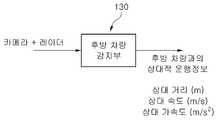
본 발명에 따른 자동 긴급 제동 시스템은 차량 정보 출력부(110), 전방 차량 감지부(120), 후방 차량 감지부(130), AEB 제어부(140) 및 제동부(150)를 포함한다.The automatic emergency braking system includes a vehicle
차량 정보 출력부(110)는 자차량의 운행 정보를 출력한다.The vehicle
자차량의 운행 정보에 대한 구체적인 실시예는 자차속, 요레이트(Yawrate) 정보 및 스트어링(Steering) 정보를 포함한다.Specific examples of the driving information of the present vehicle include the car speed, yaw rate information, and steering information.
자차량의 운전 정보를 획득하기 차량 정보 출력부는 차량에 설치된 복수개의 센서일 수 있다. 바퀴 회전속도를 감지하는 휠 스피드 센서, 스티어링 휠의 회전각도를 감지하는 조향각 센서, 차체의 회전율을 감지하는 요 레이트(yaw rate)센서등 각각의 기능을 수행하기 위한 별도의 센서들이 설치될 수 있다. 차량 정보 출력부(110)는 옆 방향 가속도 센서와 차체의 옆 방향 기울기를 감지하는 롤 레이트(roll rate) 센서일 수도 있다.Obtaining Operation Information of the Vehicle The vehicle information output unit may be a plurality of sensors installed in the vehicle. A wheel speed sensor for sensing a wheel rotation speed, a steering angle sensor for sensing a rotation angle of the steering wheel, and a yaw rate sensor for sensing a rotation rate of the vehicle body, may be installed as separate sensors . The vehicle
그러나, AEB 제어부(140)는 차량 정보 출력부(110)인 복수개의 센서로 전달된 여러개의 정보를 조합하여 이용할 수 있다.However, the AEB
전방 차량 감지부(120)는 자차량의 운행 방향에 대하여 자차량의 전방에 위치된 전방 차량과의 상대적 운행 정보를 AEB제어부(140)에 출력한다.The front
후방 차량 감지부(130)는 자차량의 운행 방향에 대하여 자차량의 후방에 위치된 후방 차량과의 상대적 운행 정보를 출력한다.The rear
AEB(Autonomous Emergency Breaking) 제어부(140)는 자차량의 운행 정보, 전방 차량과의 상대적 운행 정보 및 후방 차량과의 상대적 운행 정보를 고려하여 자차량의 제동 여부를 제어한다.The AEB (Autonomous Emergency Breaking)
제동부(150)는 AEB 제어부의 명령에 의해 자차량의 제동을 수행한다.The
도 2는 본 발명에 따른 전방 차량 감지부의 동작을 개략적으로 설명하는 도면이다.FIG. 2 is a view for schematically explaining the operation of the front vehicle sensing unit according to the present invention.
상술한 바와 같이, 전방 차량 감지부(120)는 자차량의 운행 방향에 대하여 자차량의 전방에 위치된 전방 차량과의 상대적 운행 정보를 AEB제어부(140)에 출력한다.As described above, the front
전방 차량 감지부에서 출력하는 상대적 운행 정보는 자차량과 전방 차량과의 상대 거리, 상대 속도 및 상대 가속도를 포함한다.The relative driving information output from the front vehicle detecting unit includes a relative distance, a relative speed, and a relative acceleration between the vehicle and the preceding vehicle.
전방 차량 감지부(120)는 자차량의 운행방향에서의 전방에 설치된 카메라 일 수 있다. 카메라에서 획득된 전방 영상에서 감지된 전방 차량의 물리적 측정값을 AEB 제어부로 송출한다. 송출되는 물리적 측정값은 자차량과 전방 차량의 운행방향에서의 상대거리, 상대 속도 및 상대 가속도일 수 있다.The front
전방 차량 감지부의 일 실시예로 카메라를 언급하였으나 본원 발명에서의 전방 차량 감시부가 이에 한정되는 것은 아니다.Although the camera is referred to as an embodiment of the front vehicle detection unit, the front vehicle monitoring unit in the present invention is not limited thereto.
전방 차량 감지부의 다른 구체적인 실시예는 라이더(LIDAR)일 수 있다.Another specific embodiment of the front vehicle sensing unit may be a LIDAR.
특별히 시가지 주행 모드에서는 단거리 레이저 레이더인 라이더(LIDAR)를 이용해 약 10m 전방의 장애물을 인식할 수 있다.Particularly in the city driving mode, a short distance laser radar (LIDAR) can be used to detect obstacles about 10 m ahead.
또 전방 차량 감지부는 두가지 이상의 센서를 퓨전 또는 통합 처리하여 AEB 제어부에 정보를 전달하도록 구성될 수 있다.The front vehicle detection unit may be configured to transmit information to the AEB control unit by performing fusion or integration processing of two or more sensors.
본원 발명에서는 충돌 위험성이 있는 대상을 차량으로 제한하여 언급하고 있으나, 반드시 이에 한정되는 것은 아니며 대상이 사람이나 살아 움직이는 동물이 될 수도 있음은 당업자에 자명한 사실이다.In the present invention, a person having a risk of collision is limited to a vehicle, but the present invention is not limited thereto, and it is obvious to a person skilled in the art that the object can be a person or a moving animal.
카메라 및 라이더에 의해 수집된 정보를 조합하여 전방에 있는 물체의 종류나 움직임을 파악한다. 즉, 두가지 센서를 퓨전(통합 처리)하여 시가지 주행 모드를 구현하는 것이다. 이 경우에도 대상 물체가 선행 차량인가, 아니면 보행자인가에 따라서 센서의 종류 및 사용 방법이 달라질 수 있다.Combine the information collected by the camera and the rider to determine the type and motion of the object in front. In other words, the two sensors are fusion (integrated processing) to realize the city driving mode. In this case, the type and usage of the sensor may be changed depending on whether the target object is a preceding vehicle or a pedestrian.
차량의 경우에는 라이더의 반사광 측정값이 주된 신호가 되지만, 보행자의 경우에는 화상 인식으로 먼저 대상 물체를 확인한 뒤 라이더로는 움직임을 읽는 방식을 취할 수 있다. 즉, 같은 센서라 하더라도 대상 물체에 따라서 적용되는 알고리즘이 달라질 수 있다.In the case of a vehicle, the reflected light measurement value of the rider is the main signal. However, in the case of a pedestrian, the object can be first identified by image recognition, and then the motion can be read by the rider. That is, even the same sensor can be applied to different algorithms depending on the object.
정보 획득을 위한 센서의 일 실시예로는 좌우 감지 폭이 넓은 단거리 광폭 레이더나 야간에도 인식률이 높은 적외선 카메라 등을 들 수 있다.One example of the sensor for acquiring information is a short-range wide-angle radar having wide lateral sensing range and an infrared camera having high recognition rate at night.
속도가 높은 외곽 주행 모드에서는 장거리 감지에 유리한 극초단파 레이더를 주 센서로 사용할 수 있다. 두개의 레이더를 퓨전하여 전후 속도 차이는 물론 좌우 움직임까지 인식하여 선행 차량의 상대 속도를 넓은 각도에서 더욱 정교하게 파악하는 스테레오 레이더 시스템이 전방 차량 감지부(120)의 구체적인 일 실시예가 될 수 있다. 카메라 화상 인식 기능을 접목하여 정밀도를 높이는 레이더-카메라 퓨전 시스템도 전방 차량 감지부(120)의 대표적인 실시예이다.In high-speed out-of-round mode, a microwave radar that is advantageous for long-range sensing can be used as the main sensor. A stereo radar system for recognizing the front and rear speed differences as well as the left and right motions by fusing two radars and grasping the relative speed of the preceding vehicle at a wide angle can be a concrete example of the front
나이트비전의 적외선 카메라, 거리는 짧으나 감지 폭이 넓은 주차 보조용 초음파 센서 어레이는 보행자용 AEB의 아주 좋은 실시예인 센서가 될 수 있다.Night Vision Infrared Camera, Parking Assist Ultrasonic Sensor Array with Short Distance but Wide Sensing Range can be a very good embodiment of AEB for pedestrian.
일부 어댑티브 크루즈 컨트롤 시스템들이 사용하고 있는 장거리 지향성 레이더와 단거리 광폭 레이더의 조합은 단일 AEB 시스템으로 시가지부터 외곽주행까지 폭넓게 그리고 복잡하지 않은 시스템 구성으로 커버할 가능성을 높인다. 하이빔 어시스트 또는 스마트 헤드라이트는 약간 또는 악천후 시에도 AEB의 신뢰도를 높여준다.The combination of long-range directional radar and short-range wide-angle radar used by some adaptive cruise control systems increases the likelihood of covering a wide range of uncomplicated system configurations, from city to outskirts with a single AEB system. High beam assist or smart headlamps increase the reliability of AEB even in slight or bad weather conditions.
도 3은 본 발명에 따른 후방 차량 감지부의 동작을 개략적으로 설명하는 도면이다.FIG. 3 is a view for schematically explaining the operation of the rear vehicle sensing unit according to the present invention.
후방 차량 감지부(130)는 자차량의 운행 방향에 대하여 자차량의 후방에 위치된 후방 차량과의 상대적 운행 정보를 출력한다.The rear
후방 차량 감지부(130)에서 출력하는 상대적 운행 정보는 자차량과 후방 차량과의 상대 거리, 상대 속도 및 상대 가속도를 포함한다.The relative driving information output from the rear
후방 차량 감지부의 구체적인 실시예는 상기 전방 차량 감지부에서 언급된 여러 종류의 센서가 될 수 있다. 또한, 전방 차량 감지부(120)에서 언급한 바와 같이 센서의 퓨전에 의해 구현될 수도 있음에 유의한다.A specific embodiment of the rear vehicle sensing unit may be various kinds of sensors mentioned in the front vehicle sensing unit. Note that it may also be realized by fusion of the sensor as mentioned in the front
도 4는 본 발명에 따른 AEB 제어부에 알고리즘 될 수 있는 동작 흐름도의 일 실시예를 보여주는 도면이다.4 is a flowchart illustrating an operation of the AEB control unit according to an embodiment of the present invention.
AEB제어부(140)는 전방 차량과의 충돌 위험도 및 후방 차량과의 충돌 위험도를 동시에 고려하여 제동부(150)를 제어한다.The
또한, 후방 차량과의 충돌 위험도에 따라 제동력을 차등 인가한다.In addition, the braking force is differentiated according to the risk of collision with the rear vehicle.
본 발명의 AEB제어부는 전방 차량 감지부(120)로부터 전달된 정보를 기초로 전방 차량과의 위험도를 산출한다(S410).The AEB control unit of the present invention calculates the risk with respect to the preceding vehicle based on the information transmitted from the front vehicle sensing unit 120 (S410).
전방 차량과의 충돌 위험도(TTC : Time To Contact(S))는 아래의 수학식 1에 의해 획득될 수 있다.The risk of collision with a preceding vehicle (TTC: Time To Contact (S)) can be obtained by the following equation (1).
<수학식 1>&Quot; (1) "
상대 가속도가 0이 아닐 경우;When the relative acceleration is not 0;
TTC = = (-상대속도 + sqrt(상대속도^2-2*상대거리*상대가속도))/상대가속도
TTC = = (- relative speed + sqrt (relative speed ^ 2-2 * relative distance * relative acceleration)) / relative acceleration
상대 가속도가 0일 경우;When the relative acceleration is 0;
TTC = (-상대거리/상대속도)
TTC = (- relative distance / relative speed)
동일하게 후방 차량 감지부(130)로부터 전달된 정보를 기초로 후방 차량과의 위험도를 산출한다(S420).Similarly, the risk with the rear vehicle is calculated based on the information transmitted from the rear vehicle sensing unit 130 (S420).
후방 차량과의 충돌 위험도(TTC)는 아래의 수학식 2에 의해 산출될 수 있다.
The collision risk (TTC) with the rear vehicle can be calculated by the following equation (2).
<수학식 2>&Quot; (2) "
상대 가속도가 0이 아닐 경우;When the relative acceleration is not 0;
TTC = = (-상대속도 + sqrt(상대속도^2-2*상대거리*상대가속도))/상대가속도
TTC = = (- relative speed + sqrt (relative speed ^ 2-2 * relative distance * relative acceleration)) / relative acceleration
상대 가속도가 0일 경우;When the relative acceleration is 0;
TTC = (-상대거리/상대속도)TTC = (- relative distance / relative speed)
AEB 제어부(140)는 사전에 미리 알고리즘화되어 설정될 수 있다.The
운전자의 주위를 환기시키기 위한 전방 차량과의 위험도(TTC)는 충돌 예측 시간이 2.3초로 설정될 수 있다. (S430)The risk (TTC) with the preceding vehicle for ventilating the surroundings of the driver can be set to a predicted collision time of 2.3 seconds. (S430)
동일하게 후방 차량과의 충돌 가능성에 대하여도 위험도가 동일하거나 또는 다른 값으로 설정될 수 있다.(S440)Likewise, the possibility of collision with the rear vehicle may be set to the same or different values (S440)
전방 차량과의 충돌 위험도 및 후방 차량과의 충돌 위험도를 동시에 고려하여 축소 제동 또는 AEB에 의한 제동을 수행하지 않도록 설정될 수 있다.(S450)It may be set not to perform the reduction braking or the braking by the AEB in consideration of the risk of collision with the front vehicle and the risk of collision with the rear vehicle (S450).
만약 AEB에 의한 제동이 수행되지 않는 경우에는 오로지 운전자의 개입에 의한 제동만이 수행될 뿐이다. 도 6에서 보다 상세하게 설명될 것이지만, 축소제동의 경우에 위험도(TTC)가 2.3초보다 짧은 경우에는 단지 운전자에 위험을 인식시키기 위한 Warning 동작만 수행하도록 설정될 수 있다.If the braking by the AEB is not performed, only the braking by the driver's intervention is performed. As will be described in more detail with reference to FIG. 6, in the case of reduced braking, if the risk of danger (TTC) is shorter than 2.3 seconds, it may be set to perform only a warning operation to recognize the danger to the driver.
후방 차량과의 충돌 위험이 없는 경우에는 운전자의 개입이 없더라도 AEB에 의해 자동으로 경고(1단계), 사전제동단계(2단계), 제동단계(3단계)의 순차적인 동작을 수행할 수 있다.If there is no risk of collision with the rear vehicle, the AEB can automatically perform the following sequence of operations: a warning (step 1), a pre-braking step (step 2), and a braking step (step 3).
사전제동단계는 운전자가 늦게 브레이크 페달을 밟아도 최대한의 제동 성능을 발휘할 수 있도록 제동 계통의 압력을 미리 높여 놓고 브레이크 패드와 디스크의 간격을 좁혀놓는 등 사전 준비를 수행하는 것을 의미할 수 있다.The pre-braking step may mean preliminary preparation such as increasing the pressure of the braking system in advance so that the braking performance can be maximized even when the driver presses the brake pedal later, and the gap between the brake pad and the disc is narrowed.
도 5는 본 발명에 따른 AEB 제어부에 알고리즘 될 수 있는 동작 흐름도의 다른 실시예를 보여주는 도면이다.5 is a diagram showing another embodiment of an operation flow chart that can be algorithmically executed by the AEB controller according to the present invention.
도 4에서의 알고리즘은 제동부의 동작 전에 즉 사전 동작을 수행하기 위한 것이다.The algorithm in Fig. 4 is for performing the pre-operation before the operation of the braking section.
이에 반하여, 도 5는 제동부의 동작 중에 후방 차량과의 충돌 위험도를 판단하여 제동부의 제동을 유지할 지 여부를 제어하기 위한 알고리즘의 실시예이다.On the other hand, FIG. 5 shows an embodiment of an algorithm for controlling whether or not the braking of the braking section is maintained by determining the risk of collision with the rear vehicle during operation of the braking section.
도 5에 도시된 바와 같이, AEB제어부(140)는 제동부(150)의 동작 중에 후방 차량과의 충돌 위험도를 고려하여 제동부의 동작을 해제할 수 있다.As shown in FIG. 5, the
즉, 후방 차량과의 충돌 위험도(TTC)가 0.2초보다 짧을 때는 제동부(150)에 의한 제동을 해제하고, 단지 운전자의 개입에 의한 차량의 제어만이 수행되는 것이다.That is, when the collision risk TTC with the rear vehicle is shorter than 0.2 seconds, the braking by the
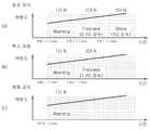
도 6은 본 발명에 따른 자동 긴급 제동 시스템의 제어 방법의 예를 도시한 도면이다.6 is a diagram showing an example of a control method of the automatic emergency braking system according to the present invention.
도 6 은 본 발명에 따른 자동 긴급 제동 시스템의 제어 방법을 도식화한 것이다.6 is a diagram illustrating a control method of an automatic emergency braking system according to the present invention.
도 6(a)는 정상제어의 경우에 위험도가 2.3초보다 짧은 경우에는 운전자에 주의를 환기시키는 경고등이나 경보음을 발생시킨다.Fig. 6 (a) shows a warning lamp or a warning sound to warn the driver when the risk is shorter than 2.3 seconds in the case of normal control.
위험도가 1.5초보다 짧은 경우에는 사전제동동작을 수행하도록 AEB제어부(140)가 알고리즘된다.If the risk is shorter than 1.5 seconds, the
위험도가 1.0보다 짧은 경우에는 제동부(150)에 의한 제동이 가해진다.If the risk is less than 1.0, braking by the
도 6(b)는 축소 제동을 위한 실시예를 도시한 것으로, 정상 동작단계에서의 제동단계가 없는 것이다.6 (b) shows an embodiment for reducing braking, and there is no braking step in the normal operating phase.
후방차량과의 충돌 위험이 1.5초보다 짧은 경우에는 AEB에 의한 자동 제동시 후방 차량과의 충돌이 거의 확실시 된다고 예측하여 운전자에 의한 제동을 유도하도록 정상 제어(도 6(a))에서의 경고 표시보다 강력한 경고 동작을 하도록 설정될 수 있다.When the risk of collision with the rear vehicle is shorter than 1.5 seconds, it is predicted that the collision with the rear vehicle is almost certain during the automatic braking by the AEB, so that the warning in the normal control (Fig. 6 (a) It can be set to perform a stronger warning operation.
도 6(c)의 제동 금지단계는 AEB에 의한 제동이 없이 단지 운전자에 제동을 수행하도록 경고 동작만을 수행하도록 설정될 수 있다.The braking prohibition step of Fig. 6 (c) can be set to perform only the warning operation so as to perform the braking on the driver only without braking by the AEB.
즉, 후방 차량과의 충돌 가능성이 2.3초보다 짧은 경우에는 경고동작만을 수행하도록 설정되고 AEB 제어부 및 제동부(150)에 의한 추가적인 동작은 수행되지 않는 것이다.That is, when the possibility of collision with the rear vehicle is shorter than 2.3 seconds, only the warning operation is set to be performed, and the additional operation by the AEB control unit and the
본 발명은 상기 실시예에 한정되지 않고, 본 발명의 기술적 요지를 벗어나지 아니하는 범위 내에서 다양하게 수정 또는 변형되어 실시될 수 있음은 본 발명이 속하는 기술분야에서 통상의 지식을 가진 자에 있어서 자명한 것이다.
It will be apparent to those skilled in the art that various modifications and variations can be made in the present invention without departing from the spirit and scope of the invention. It is.
110 : 차량 정보 출력부
120 : 전방 차량 감지부
130 : 후방 차량 감지부
140 : AEB 제어부
150 : 제동부110: vehicle information output unit
120: Front vehicle detection unit
130: rear vehicle detection unit
140: AEB control unit
150:
Claims (7)
Translated fromKorean자차량의 운행 정보를 출력하는 차량 정보 출력부;
상기 자차량의 운행 방향에 대하여 상기 자차량의 전방에 위치된 전방 차량과의 상대적 운행 정보를 출력하는 전방 차량 감지부;
상기 자차량의 운행 방향에 대하여 상기 자차량의 후방에 위치된 후방 차량과의 상대적 운행 정보를 출력하는 후방 차량 감지부;
상기 자차량의 운행 정보, 상기 전방 차량과의 상대적 운행 정보 및 상기 후방 차량과의 상대적 운행 정보를 고려하여 상기 자차량의 제동 여부를 제어하는 AEB(Autonomous Emergency Breaking) 제어부; 및
상기 제어부의 명령에 의해 상기 자차량의 제동을 수행하는 제동부;를 포함하는 것을 특징으로 하는, 자동 긴급 제동 시스템.
In an automatic emergency braking system for a vehicle,
A vehicle information output unit for outputting driving information of the vehicle;
A front vehicle sensing unit for outputting relative driving information with respect to the front vehicle positioned in front of the vehicle in relation to the traveling direction of the vehicle;
A rear vehicle sensing unit for outputting relative driving information with respect to the rear vehicle located behind the vehicle in relation to the traveling direction of the vehicle;
An AEB (Autonomous Emergency Breaking) controller for controlling the braking of the subject vehicle in consideration of the driving information of the subject vehicle, the relative driving information with respect to the preceding vehicle, and the relative driving information with respect to the rear vehicle; And
And a braking unit that performs braking of the child vehicle by an instruction from the control unit.
상기 자차량의 운행 정보는 자차속, 요레이트(Yawrate) 정보 및 스트어링(Steering) 정보를 포함하는 것을 특징으로 하는, 자동 긴급 제동 시스템.
The method according to claim 1,
Wherein the driving information of the subject vehicle includes a subject vehicle speed, yaw rate information, and steering information.
상기 전방 차량 감지부에서 출력하는 상기 상대적 운행 정보는 상기 자차량과 상기 전방 차량과의 상대 거리, 상대 속도 및 상대 가속도를 포함하는, 자동 긴급 제동 시스템.
The method according to claim 1,
Wherein the relative driving information output from the front vehicle sensing unit includes a relative distance between the host vehicle and the preceding vehicle, a relative speed, and a relative acceleration.
상기 후방 차량 감지부에서 출력하는 상기 상대적 운행 정보는 상기 자차량과 상기 후방 차량과의 상대 거리, 상대 속도 및 상대 가속도를 포함하는, 자동 긴급 제동 시스템.
The method according to claim 1,
Wherein the relative driving information output from the rear vehicle detecting unit includes a relative distance, a relative speed, and a relative acceleration between the child vehicle and the rear vehicle.
상기 AEB제어부는 상기 전방 차량과의 충돌 위험도 및 상기 후방 차량과의 충돌 위험도를 동시에 고려하여 상기 제동부를 제어하되,
상기 후방 차량과의 충돌 위험도에 따라 제동력을 차등 인가하는 것을 특징으로 하는, 자동 긴급 제동 시스템.
The method according to claim 1,
Wherein the AEB control unit controls the braking unit by simultaneously considering the risk of collision with the preceding vehicle and the risk of collision with the back vehicle,
Characterized in that the braking force is differentiated according to the risk of collision with the rear vehicle.
상기 후방 차량과의 충돌 위험도에 따라 상기 AEB 제어부는 단지 운전자에 사전 경고를 위한 경보음이나 경고등 출력만을 지시하는 것을 특징으로 하는, 자동 긴급 제동 시스템.
The method of claim 5,
Wherein the AEB control unit only instructs the driver to output an alarm sound or a warning light for a warning in accordance with the risk of collision with the rear vehicle.
상기 AEB제어부는 상기 제동부의 동작 중에 상기 후방 차량과의 충돌 위험도를 고려하여 상기 제동부의 동작을 해제하는 것을 특징으로 하는, 자동 긴급 제동 시스템.
The method according to claim 1,
Wherein the AEB control unit releases the operation of the braking unit in consideration of the risk of collision with the rear vehicle during operation of the braking unit.
Priority Applications (1)
| Application Number | Priority Date | Filing Date | Title |
|---|---|---|---|
| KR1020150053259AKR102362178B1 (en) | 2015-04-15 | 2015-04-15 | Autonomous emergency braking system |
Applications Claiming Priority (1)
| Application Number | Priority Date | Filing Date | Title |
|---|---|---|---|
| KR1020150053259AKR102362178B1 (en) | 2015-04-15 | 2015-04-15 | Autonomous emergency braking system |
Publications (2)
| Publication Number | Publication Date |
|---|---|
| KR20160123110Atrue KR20160123110A (en) | 2016-10-25 |
| KR102362178B1 KR102362178B1 (en) | 2022-02-14 |
Family
ID=57446284
Family Applications (1)
| Application Number | Title | Priority Date | Filing Date |
|---|---|---|---|
| KR1020150053259AActiveKR102362178B1 (en) | 2015-04-15 | 2015-04-15 | Autonomous emergency braking system |
Country Status (1)
| Country | Link |
|---|---|
| KR (1) | KR102362178B1 (en) |
Cited By (4)
| Publication number | Priority date | Publication date | Assignee | Title |
|---|---|---|---|---|
| CN109572658A (en)* | 2017-09-29 | 2019-04-05 | 株式会社万都 | Brake control and brake control method |
| CN109624942A (en)* | 2018-11-23 | 2019-04-16 | 中汽研(天津)汽车工程研究院有限公司 | A kind of high low speed switching brake control method of AEB system and control device |
| CN110281924A (en)* | 2018-03-19 | 2019-09-27 | 现代自动车株式会社 | Vehicle and the method for controlling the vehicle |
| KR20200096351A (en) | 2019-02-01 | 2020-08-12 | 주식회사 만도 | Emergency braking system and method for controlling the same |
Citations (7)
| Publication number | Priority date | Publication date | Assignee | Title |
|---|---|---|---|---|
| JP2951451B2 (en)* | 1991-10-15 | 1999-09-20 | ダイハツ工業株式会社 | Brake control method for rear-end collision prevention system |
| JP2007168504A (en)* | 2005-12-20 | 2007-07-05 | Nissan Motor Co Ltd | Rear impact impact energy reduction device for vehicles |
| JP2008189055A (en)* | 2007-02-01 | 2008-08-21 | Toyota Motor Corp | Tracking control device |
| JP2008290600A (en)* | 2007-05-25 | 2008-12-04 | Nissan Diesel Motor Co Ltd | Travel control device of vehicle |
| JP2009070254A (en)* | 2007-09-14 | 2009-04-02 | Nissan Motor Co Ltd | Vehicle risk estimation device |
| JP2013133096A (en)* | 2011-12-26 | 2013-07-08 | Hyundai Motor Co Ltd | Inter-vehicle distance control system and method using side rear sensing sensor |
| KR20130114782A (en)* | 2012-04-10 | 2013-10-21 | 주식회사 만도 | Collision prevention system for vehicle |
- 2015
- 2015-04-15KRKR1020150053259Apatent/KR102362178B1/enactiveActive
Patent Citations (7)
| Publication number | Priority date | Publication date | Assignee | Title |
|---|---|---|---|---|
| JP2951451B2 (en)* | 1991-10-15 | 1999-09-20 | ダイハツ工業株式会社 | Brake control method for rear-end collision prevention system |
| JP2007168504A (en)* | 2005-12-20 | 2007-07-05 | Nissan Motor Co Ltd | Rear impact impact energy reduction device for vehicles |
| JP2008189055A (en)* | 2007-02-01 | 2008-08-21 | Toyota Motor Corp | Tracking control device |
| JP2008290600A (en)* | 2007-05-25 | 2008-12-04 | Nissan Diesel Motor Co Ltd | Travel control device of vehicle |
| JP2009070254A (en)* | 2007-09-14 | 2009-04-02 | Nissan Motor Co Ltd | Vehicle risk estimation device |
| JP2013133096A (en)* | 2011-12-26 | 2013-07-08 | Hyundai Motor Co Ltd | Inter-vehicle distance control system and method using side rear sensing sensor |
| KR20130114782A (en)* | 2012-04-10 | 2013-10-21 | 주식회사 만도 | Collision prevention system for vehicle |
Cited By (9)
| Publication number | Priority date | Publication date | Assignee | Title |
|---|---|---|---|---|
| CN109572658A (en)* | 2017-09-29 | 2019-04-05 | 株式会社万都 | Brake control and brake control method |
| KR20190037750A (en)* | 2017-09-29 | 2019-04-08 | 주식회사 만도 | Brake Control Apparatus and Control Method Thereof |
| CN109572658B (en)* | 2017-09-29 | 2022-08-02 | 株式会社万都 | Brake control device and brake control method |
| US11414090B2 (en) | 2017-09-29 | 2022-08-16 | Mando Corporation | Brake control apparatus and brake control method |
| CN110281924A (en)* | 2018-03-19 | 2019-09-27 | 现代自动车株式会社 | Vehicle and the method for controlling the vehicle |
| CN109624942A (en)* | 2018-11-23 | 2019-04-16 | 中汽研(天津)汽车工程研究院有限公司 | A kind of high low speed switching brake control method of AEB system and control device |
| CN109624942B (en)* | 2018-11-23 | 2024-05-28 | 中汽研(天津)汽车工程研究院有限公司 | AEB system high-low speed switching braking control method and control device |
| KR20200096351A (en) | 2019-02-01 | 2020-08-12 | 주식회사 만도 | Emergency braking system and method for controlling the same |
| US11279329B2 (en) | 2019-02-01 | 2022-03-22 | Mando Mobility Solutions Corporation | Emergency braking system and method of controlling the same |
Also Published As
| Publication number | Publication date |
|---|---|
| KR102362178B1 (en) | 2022-02-14 |
Similar Documents
| Publication | Publication Date | Title |
|---|---|---|
| CN112706763B (en) | Vehicle and method of controlling the same | |
| US10661792B2 (en) | System and method for performing autonomous emergency braking | |
| CN108263279B (en) | Sensor integration based pedestrian detection and pedestrian collision avoidance apparatus and method | |
| JP7200871B2 (en) | Collision avoidance support device | |
| US10259453B2 (en) | Collision avoidance based on front wheel off tracking during reverse operation | |
| US9656667B2 (en) | Method for minimizing automatic braking intrusion based on collision confidence | |
| KR101489836B1 (en) | Pedestrian detecting and collision avoiding apparatus and method thereof | |
| US11938924B2 (en) | Driving assistance control apparatus for vehicle, driving assistance control system for vehicle, and driving assistance control method for vehicle | |
| EP3254918B1 (en) | Adaptive cruise control system and vehicle comprising an adaptive cruise control system | |
| US20080015743A1 (en) | Method and system for assisting the driver of a motor vehicle in identifying road bumps | |
| JP2019084885A (en) | Lane change support device | |
| JP6849575B2 (en) | Braking support device and braking support control method in a vehicle | |
| CN113147747A (en) | Apparatus for assisting vehicle driving and method thereof | |
| KR101552017B1 (en) | Performance enhanced driver assistance systems and controlling method for the same | |
| KR102720780B1 (en) | Vehicle, and control method for the same | |
| US20210122369A1 (en) | Extensiview and adaptive lka for adas and autonomous driving | |
| KR20210079946A (en) | Vehicle and control method thereof | |
| US20170174212A1 (en) | Method for operating a motor vehicle | |
| JP7306887B2 (en) | vehicle controller | |
| KR20210152144A (en) | Driver assistance apparatus and driver assisting method | |
| KR102362178B1 (en) | Autonomous emergency braking system | |
| KR20220166119A (en) | Driver assistance system and method thereof | |
| KR102440265B1 (en) | driver assistance system | |
| JP7566156B2 (en) | How the vehicle operates during autonomous driving | |
| KR20210080717A (en) | Driver assistance apparatus and driver assisting method |
Legal Events
| Date | Code | Title | Description |
|---|---|---|---|
| PA0109 | Patent application | Patent event code:PA01091R01D Comment text:Patent Application Patent event date:20150415 | |
| PG1501 | Laying open of application | ||
| A201 | Request for examination | ||
| PA0201 | Request for examination | Patent event code:PA02012R01D Patent event date:20200407 Comment text:Request for Examination of Application Patent event code:PA02011R01I Patent event date:20150415 Comment text:Patent Application | |
| E902 | Notification of reason for refusal | ||
| PE0902 | Notice of grounds for rejection | Comment text:Notification of reason for refusal Patent event date:20210623 Patent event code:PE09021S01D | |
| PN2301 | Change of applicant | Patent event date:20210929 Comment text:Notification of Change of Applicant Patent event code:PN23011R01D | |
| E701 | Decision to grant or registration of patent right | ||
| PE0701 | Decision of registration | Patent event code:PE07011S01D Comment text:Decision to Grant Registration Patent event date:20220120 | |
| GRNT | Written decision to grant | ||
| PR0701 | Registration of establishment | Comment text:Registration of Establishment Patent event date:20220208 Patent event code:PR07011E01D | |
| PR1002 | Payment of registration fee | Payment date:20220209 End annual number:3 Start annual number:1 | |
| PG1601 | Publication of registration | ||
| PR1001 | Payment of annual fee | Payment date:20241223 Start annual number:4 End annual number:4 |