KR20160121116A - Electronic device - Google Patents
Electronic deviceDownload PDFInfo
- Publication number
- KR20160121116A KR20160121116AKR1020150050641AKR20150050641AKR20160121116AKR 20160121116 AKR20160121116 AKR 20160121116AKR 1020150050641 AKR1020150050641 AKR 1020150050641AKR 20150050641 AKR20150050641 AKR 20150050641AKR 20160121116 AKR20160121116 AKR 20160121116A
- Authority
- KR
- South Korea
- Prior art keywords
- module
- main body
- electronic device
- connection terminals
- unit
- Prior art date
- Legal status (The legal status is an assumption and is not a legal conclusion. Google has not performed a legal analysis and makes no representation as to the accuracy of the status listed.)
- Granted
Links
Images


Classifications
- G—PHYSICS
- G06—COMPUTING OR CALCULATING; COUNTING
- G06F—ELECTRIC DIGITAL DATA PROCESSING
- G06F1/00—Details not covered by groups G06F3/00 - G06F13/00 and G06F21/00
- G06F1/16—Constructional details or arrangements
- G06F1/1613—Constructional details or arrangements for portable computers
- G06F1/1633—Constructional details or arrangements of portable computers not specific to the type of enclosures covered by groups G06F1/1615 - G06F1/1626
- G06F1/1684—Constructional details or arrangements related to integrated I/O peripherals not covered by groups G06F1/1635 - G06F1/1675
- G06F1/1698—Constructional details or arrangements related to integrated I/O peripherals not covered by groups G06F1/1635 - G06F1/1675 the I/O peripheral being a sending/receiving arrangement to establish a cordless communication link, e.g. radio or infrared link, integrated cellular phone
- G—PHYSICS
- G06—COMPUTING OR CALCULATING; COUNTING
- G06F—ELECTRIC DIGITAL DATA PROCESSING
- G06F1/00—Details not covered by groups G06F3/00 - G06F13/00 and G06F21/00
- G06F1/16—Constructional details or arrangements
- G06F1/18—Packaging or power distribution
- G06F1/181—Enclosures
- G—PHYSICS
- G06—COMPUTING OR CALCULATING; COUNTING
- G06F—ELECTRIC DIGITAL DATA PROCESSING
- G06F1/00—Details not covered by groups G06F3/00 - G06F13/00 and G06F21/00
- G06F1/16—Constructional details or arrangements
- G06F1/1613—Constructional details or arrangements for portable computers
- G—PHYSICS
- G06—COMPUTING OR CALCULATING; COUNTING
- G06F—ELECTRIC DIGITAL DATA PROCESSING
- G06F1/00—Details not covered by groups G06F3/00 - G06F13/00 and G06F21/00
- G06F1/16—Constructional details or arrangements
- G06F1/18—Packaging or power distribution
- G06F1/183—Internal mounting support structures, e.g. for printed circuit boards, internal connecting means
- G—PHYSICS
- G06—COMPUTING OR CALCULATING; COUNTING
- G06F—ELECTRIC DIGITAL DATA PROCESSING
- G06F1/00—Details not covered by groups G06F3/00 - G06F13/00 and G06F21/00
- G06F1/16—Constructional details or arrangements
- G06F1/1613—Constructional details or arrangements for portable computers
- G06F1/1633—Constructional details or arrangements of portable computers not specific to the type of enclosures covered by groups G06F1/1615 - G06F1/1626
- G06F1/1635—Details related to the integration of battery packs and other power supplies such as fuel cells or integrated AC adapter
- G—PHYSICS
- G06—COMPUTING OR CALCULATING; COUNTING
- G06F—ELECTRIC DIGITAL DATA PROCESSING
- G06F1/00—Details not covered by groups G06F3/00 - G06F13/00 and G06F21/00
- G06F1/16—Constructional details or arrangements
- G06F1/1613—Constructional details or arrangements for portable computers
- G06F1/1633—Constructional details or arrangements of portable computers not specific to the type of enclosures covered by groups G06F1/1615 - G06F1/1626
- G06F1/1656—Details related to functional adaptations of the enclosure, e.g. to provide protection against EMI, shock, water, or to host detachable peripherals like a mouse or removable expansions units like PCMCIA cards, or to provide access to internal components for maintenance or to removable storage supports like CDs or DVDs, or to mechanically mount accessories
- G06F1/1658—Details related to functional adaptations of the enclosure, e.g. to provide protection against EMI, shock, water, or to host detachable peripherals like a mouse or removable expansions units like PCMCIA cards, or to provide access to internal components for maintenance or to removable storage supports like CDs or DVDs, or to mechanically mount accessories related to the mounting of internal components, e.g. disc drive or any other functional module
- G—PHYSICS
- G06—COMPUTING OR CALCULATING; COUNTING
- G06F—ELECTRIC DIGITAL DATA PROCESSING
- G06F1/00—Details not covered by groups G06F3/00 - G06F13/00 and G06F21/00
- G06F1/16—Constructional details or arrangements
- G06F1/1613—Constructional details or arrangements for portable computers
- G06F1/1633—Constructional details or arrangements of portable computers not specific to the type of enclosures covered by groups G06F1/1615 - G06F1/1626
- G06F1/1684—Constructional details or arrangements related to integrated I/O peripherals not covered by groups G06F1/1635 - G06F1/1675
- G—PHYSICS
- G06—COMPUTING OR CALCULATING; COUNTING
- G06F—ELECTRIC DIGITAL DATA PROCESSING
- G06F1/00—Details not covered by groups G06F3/00 - G06F13/00 and G06F21/00
- G06F1/16—Constructional details or arrangements
- G06F1/18—Packaging or power distribution
- G06F1/183—Internal mounting support structures, e.g. for printed circuit boards, internal connecting means
- G06F1/185—Mounting of expansion boards
- G—PHYSICS
- G06—COMPUTING OR CALCULATING; COUNTING
- G06F—ELECTRIC DIGITAL DATA PROCESSING
- G06F2200/00—Indexing scheme relating to G06F1/04 - G06F1/32
- G06F2200/16—Indexing scheme relating to G06F1/16 - G06F1/18
- G06F2200/163—Indexing scheme relating to constructional details of the computer
- G06F2200/1635—Stackable modules
Landscapes
- Engineering & Computer Science (AREA)
- Theoretical Computer Science (AREA)
- Computer Hardware Design (AREA)
- General Engineering & Computer Science (AREA)
- Human Computer Interaction (AREA)
- Physics & Mathematics (AREA)
- General Physics & Mathematics (AREA)
- Power Engineering (AREA)
- Casings For Electric Apparatus (AREA)
- Telephone Set Structure (AREA)
- Microelectronics & Electronic Packaging (AREA)
Abstract
Translated fromKoreanDescription
Translated fromKorean본 발명의 다양한 실시예는 전자 장치에 관한 것으로서, 예컨대, 개인용 컴퓨터에 관한 것이다.Various embodiments of the present invention are directed to electronic devices, such as personal computers.
정보통신 산업이 발달함에 따라, 전자 장치는 사용자로 하여금 다양한 정보를 생성, 축적하거나 제공받을 수 있는 수단을 제공할 수 있다. 초고속, 대용량 무선 통신이 보편화되면서, 이동통신 산업이 급속도로 발전하고 있지만, 개인용 컴퓨터(personal compute; PC)는 온/오프라인에서 여전히 정보를 생성, 축적하거나 제공받는데 있어 유용하게 활용되고 있다. 일반 가정이나 사무 환경에서는 데스크탑 PC가 주로 활용되어 왔으며, 사용자가 직접 각종 부품들을 교체하는 것이 비교적 용이하여, 데스크탑 PC의 기능을 확장하거나 성능을 향상시킬 수 있다.As the information and communications industry develops, electronic devices can provide a means for a user to create, store or receive a variety of information. As the high-speed and large-capacity wireless communication becomes popular, the mobile communication industry is rapidly developing, but the personal compute (PC) is still being utilized for generating, accumulating or receiving information on / off-line. Desktop PCs have been mainly used in ordinary households or office environments, and it is relatively easy for users to directly replace various components, thereby expanding functions or improving performance of desktop PCs.
일부 사용자들은 데스크탑 PC를 대신하여 노트북 PC나 태블릿 PC, All in one PC 등을 사용하고 있다. 노트북 PC나 태블릿 PC는 휴대가 가능하고, 적은 공간을 차지하는 장점이 있고, All in one PC는 별도의 부가 장치, 예컨대, 별도의 모니터를 연결할 필요가 없어 PC가 설치된 공간의 환경을 정갈하게 할 수 있다. 하지만, 노트북 PC나 태블릿 PC, All in one PC는 동일한 성능을 구현하기 위해 데스크탑 PC보다 더 많은 비용이 소요될 수 있다. 또한, 데스크탑 PC와 달리, 노트북 PC나 태블릿 PC, All in one PC는 사용자가 부품을 교체하는 것이 어려워, 사용자의 요구가 있더라도 기능을 확장하거나 성능을 향상시키는데 한계가 있다.Some users use notebook PCs, tablet PCs, All in one PCs, etc. instead of desktop PCs. The notebook PC or tablet PC is portable and has the advantage of occupying a small space. All in one PC does not require a separate additional device, for example, a separate monitor, so that the environment in which the PC is installed can be cleaned have. However, notebook PCs, tablet PCs, and all in one PCs can cost more than desktop PCs to achieve the same performance. In addition, unlike desktop PCs, notebook PCs, tablet PCs, and all in one PCs are difficult for users to replace parts, and there is a limit to expanding functions or improving performance even at the request of the user.
최근에는 전자 장치의 집적도가 높아지면서 데스크탑 PC와 노트북 PC 등의 장점을 모아 데스크탑 PC가 점차 소형화되고 있다. 하지만, 소형화된 데스크탑 PC에서도 사용자가 원하는 부품들을 직접 교체하기 어려울 수 있다. 예컨대, 소형화된 데스크탑 PC는 각종 부품들(예: 프로세서, 그래픽 모듈, 음향 모듈 등)이 하나의 통합된 카드 형태로 제공되어, 사용자의 요구에 따라 기능을 확장하거나 성능을 향상시키는데 한계가 있을 수 있다.In recent years, as the degree of integration of electronic devices has increased, the advantages of desktop PCs and notebook PCs have been gathered and desktop PCs have become smaller and smaller. However, it may be difficult to replace the parts that the user wants directly on the miniaturized desktop PC. For example, a miniaturized desktop PC may be limited in its ability to expand functions or improve performance depending on the user's needs, since various components (for example, processors, graphic modules, sound modules, etc.) have.
이에, 본 발명의 다양한 실시예는 소형화되면서도 기능을 확장하거나 성능을 향상시키기 용이한 개인용 컴퓨터 등의 전자 장치를 제공하고자 한다.Accordingly, various embodiments of the present invention are intended to provide an electronic device such as a personal computer which is miniaturized and which is capable of expanding functions or improving performance.
또한, 본 발명의 다양한 실시예는 전자 장치의 본체부와, 서로 다른 기능을 가진 모듈부들을 착탈 가능하게 구성함으로써, 필요에 따라, 기능을 확장하거나 성능을 향상시킬 수 있는 전자 장치를 제공하고자 한다.In addition, various embodiments of the present invention are intended to provide an electronic device capable of expanding functions or improving performance as needed by configuring the main body portion of the electronic device and the module portions having different functions to be removable .
또한, 본 발명의 다양한 실시예는 노트북 PC의 휴대성과 데스크탑 PC의 확장성을 확보할 수 있는 전자 장치를 제공하고자 한다.In addition, various embodiments of the present invention provide an electronic device capable of ensuring the portability of a notebook PC and the expandability of a desktop PC.
본 발명의 다양한 실시예에 따른 전자 장치는,An electronic device according to various embodiments of the present invention,
제1의 상면과, 상기 제1 상면에 대향하는 제1의 하면과, 상기 제1 상면과 제1 하면을 연결하는 제1 측면을 포함하는 본체부; 및A body portion including a first upper surface, a first lower surface opposed to the first upper surface, and a first side connecting the first upper surface and the first lower surface; And
제2의 상면과, 상기 제2 상면에 대향하는 제2의 하면과, 상기 제2 상면과 제2 하면을 연결하는 제2 측면을 각각 포함하는 적어도 하나의 모듈부를 포함할 수 있으며,And at least one module portion including a second upper surface, a second lower surface opposed to the second upper surface, and a second side connecting the second upper surface and the second lower surface,
상기 모듈부는, 상기 제2 상면, 제2 하면 및 제2 측면 중 하나가 상기 제1 상면, 제1 하면 및 제1 측면 중 하나에 대면한 상태로 상기 본체부와 또는 다른 모듈부와 착탈 가능하게 제공되고,The module unit may be configured such that one of the second top surface, the second bottom surface, and the second side is detachably attached to the main body unit or another module unit while facing one of the first top surface, the first bottom surface, and the first side surface Provided,
상기 본체부에 장착된 모듈부는 상기 본체부와 전기적으로 연결될 수 있다.The module unit mounted on the main body unit may be electrically connected to the main body unit.
상기 본체부와 모듈부(들)는 각각 원통 형상일 수 있으며, 서로 결합하여 더 큰(또는 더 긴) 원통 형상을 이룰 수 있다.The body portion and the module portion (s) may each be in the shape of a cylinder and may be joined together to form a larger (or longer) cylindrical shape.
상기 모듈부들에는 각기 다른 기능(예: 전원 기능, 그래픽 처리 기능, 카메라/프로젝터 등의 광학 기능, 저장 매체 기능 등)이 탑재되어 상기 본체부와 결합하여 상기 전자 장치의 기능을 확장하거나 성능을 향상시킬 수 있다.The module units are equipped with different functions (e.g., power function, graphic processing function, optical function such as camera / projector, storage medium function, etc.), and are combined with the main body unit to expand the functions of the electronic device .
본 발명의 다양한 실시예에 따른 전자 장치는, 본체부 자체로서 하나의 PC로 작동 가능하며, 사용자가 원하는 기능에 따라 모듈부들 중 하나 또는 복수를 선택하여 본체부에(또는 다른 모듈부)에 연결할 수 있다. 예컨대, 서로 다른 기능이 탑재된 모듈부들 중 사용자가 원하는 모듈부를 선택하여 본체부에 장착할 수 있다. 따라서 사용자는 경제적인 부담을 경감하면서도 사용자가 필요로 하는 전자 장치의 기능을 확장하거나 성능을 향상시킬 수 있다. 또한, 본체부와 모듈부를 서로 결합시키거나 분리하는 구조를 회전 방식으로(또는 스냅 핏 구조 등 다른 결속 방식으로) 구현할 수 있어, 사용자가 모듈부(들)를 본체부에 용이하게 착탈할 수 있다. 더욱이, 충전식 배터리가 내장된 모듈부를 본체부와 결합하여 본 발명의 다양한 실시예에 따른 전자 장치를 사용자가 편리하게 휴대하고 다니면서 사용할 수도 있다. 또한, 본체부와 모듈부의 소형화하면서 미려한 형상으로 제작함으로써 디자인 소품으로 활용할 수 있다.The electronic device according to various embodiments of the present invention can operate as one PC as the main body itself and connect one or more of the module parts to the main body part (or other module part) according to a function desired by the user . For example, a user can select a desired module unit among the module units having different functions and mount the selected module unit on the main body unit. Therefore, the user can expand the function of the electronic device that the user needs while improving the performance, while reducing the economic burden. Further, the structure for coupling or separating the main body portion and the module portion can be implemented in a rotating manner (or in a different binding manner such as a snap fit structure), so that the user can easily attach and detach the module portion (s) . Furthermore, the electronic device according to various embodiments of the present invention can be conveniently carried and used while the module unit with the rechargeable battery is combined with the main body unit. In addition, the body portion and the module portion can be utilized as a design prod- uct by being manufactured in a compact shape while being in a beautiful shape.
도 1은 본 발명의 다양한 실시예 중 하나에 따른 전자 장치를 나타내는 사시도이다.
도 2는 본 발명의 다양한 실시예 중 하나에 따른 전자 장치에서 본체부의 주요 구성을 나타내는 사시도이다.
도 3은 본 발명의 다양한 실시예 중 하나에 따른 전자 장치에서 본체부의 주요 구성을 나타내는 측면도이다.
도 4는 본 발명의 다양한 실시예 중 하나에 따른 전자 장치의 본체부에 제공된 결합 구조를 설명하기 위한 분리 사시도이다.
도 5는 본 발명의 다양한 실시예 중 하나에 따른 전자 장치의 모듈부들 중 하나를 예시하는 분리 사시도이다.
도 6 내지 도 9는 본 발명의 다양한 실시예 중 하나에 따른 전자 장치의 본체부와 모듈부의 전기적인 접속 구조들을 각각 나타내는 도면이다.
도 10은 본 발명의 다양한 실시예 중 다른 하나에 따른 전자 장치에서 본체부의 주요 구성을 나타내는 사시도이다.
도 11은 본 발명의 다양한 실시예 중 다른 하나에 따른 전자 장치에서 본체부의 주요 구성을 나타내는 평면도이다.
도 12는 본 발명의 다양한 실시예에 따른 전자 장치의 활용 예들을 설명하기 위한 도면이다.
도 13 내지 도 16은 본 발명의 다양한 실시예에 따른 전자 장치에서, 본체부와 모듈부들 간의 접속 구조를 각각 예시하는 도면이다.1 is a perspective view illustrating an electronic device according to one of various embodiments of the present invention.
2 is a perspective view showing a main configuration of a main body portion in an electronic device according to one of various embodiments of the present invention.
3 is a side view showing a main configuration of a main body portion in an electronic device according to one of various embodiments of the present invention.
4 is an exploded perspective view illustrating a coupling structure provided in a main body portion of an electronic device according to one of various embodiments of the present invention.
5 is an exploded perspective view illustrating one of the module portions of an electronic device according to one of various embodiments of the present invention.
6 to 9 are views each showing electrical connection structures of a main body portion and a module portion of an electronic device according to one of various embodiments of the present invention.
10 is a perspective view showing a main configuration of a main body portion in an electronic device according to another of the various embodiments of the present invention.
11 is a plan view showing a main configuration of a main body portion in an electronic device according to another of the various embodiments of the present invention.
12 is a diagram for explaining utilization examples of an electronic device according to various embodiments of the present invention.
Figs. 13 to 16 are views illustrating the connection structure between the main body part and the module parts, respectively, in an electronic device according to various embodiments of the present invention.
이하, 본 발명의 다양한 실시예가 첨부된 도면을 참조하여 기재된다. 그러나, 이는 본 발명에 기재된 기술을 특정한 실시 형태에 대해 한정하려는 것이 아니며, 본 발명의 실시예의 다양한 변경(modifications), 균등물(equivalents), 및/또는 대체물(alternatives)을 포함하는 것으로 이해되어야 한다. 도면의 설명과 관련하여, 유사한 구성요소에 대해서는 유사한 참조 부호가 사용될 수 있다.Various embodiments of the invention will now be described with reference to the accompanying drawings. It should be understood, however, that the description herein is not intended to limit the invention to the particular embodiments, but includes various modifications, equivalents, and / or alternatives of the embodiments of the invention . In connection with the description of the drawings, like reference numerals may be used for similar components.
본 발명의 다양한 실시예에서, "A 또는 B", "A 또는/및 B 중 적어도 하나" 또는 "A 또는/및 B 중 하나 또는 그 이상"등의 표현은 함께 나열된 항목들의 모든 가능한 조합을 포함할 수 있다. 예를 들면, "A 또는 B," "A 및 B 중 적어도 하나," 또는 "A 또는 B 중 적어도 하나"는, (1) 적어도 하나의 A를 포함, (2) 적어도 하나의 B를 포함, 또는 (3) 적어도 하나의 A 및 적어도 하나의 B 모두를 포함하는 경우를 모두 지칭할 수 있다.In various embodiments of the invention, the expressions "A or B," "at least one of A and / or B," or "one or more of A and / or B," and the like include all possible combinations of the listed items can do. For example, "A or B," "at least one of A and B," or "at least one of A or B" includes (1) at least one A, (2) Or (3) at least one A and at least one B all together.
본 발명에서 사용된 "제1", "제2", "첫째" 또는 "둘째"등의 표현들은 다양한 구성요소들을, 순서 및/또는 중요도에 상관없이 수식할 수 있고, 한 구성요소를 다른 구성요소와 구분하기 위해 사용될 뿐 해당 구성요소들을 한정하지 않는다. 예를 들면, 제1 사용자 기기와 제2 사용자 기기는, 순서 또는 중요도와 무관하게, 서로 다른 사용자 기기를 나타낼 수 있다. 예를 들면, 본 발명에 기재된 권리 범위를 벗어나지 않으면서 제1 구성요소는 제2 구성요소로 명명될 수 있고, 유사하게 제2 구성요소도 제1 구성요소로 바꾸어 명명될 수 있다.As used herein, the expressions "first", "second", "first" or "second" and the like can be used to express various components, And is not limited to such components. For example, the first user equipment and the second user equipment may represent different user equipment, regardless of order or importance. For example, without departing from the scope of the invention described in the present invention, the first component can be named as the second component, and similarly, the second component can also be named as the first component.
어떤 구성요소(예: 제1 구성요소)가 다른 구성요소(예: 제2 구성요소)에 "(기능적으로 또는 통신적으로) 연결되어((operatively or communicatively) coupled with/to)" 있다거나 "접속되어(connected to)" 있다고 언급된 때에는, 상기 어떤 구성요소가 상기 다른 구성요소에 직접적으로 연결되거나, 다른 구성요소(예: 제3 구성요소)를 통하여 연결될 수 있다고 이해되어야 할 것이다. 반면에, 어떤 구성요소(예: 제1 구성요소)가 다른 구성요소(예: 제2 구성요소)에 "직접 연결되어" 있다거나 "직접 접속되어" 있다고 언급된 때에는, 상기 어떤 구성요소와 상기 다른 구성요소 사이에 다른 구성요소(예: 제3 구성요소)가 존재하지 않는 것으로 이해될 수 있다.(Or functionally or communicatively) coupled with / to "another component (eg, a second component), or a component (eg, a second component) Quot; connected to ", it is to be understood that any such element may be directly connected to the other element or may be connected through another element (e.g., a third element). On the other hand, when it is mentioned that a component (e.g., a first component) is "directly connected" or "directly connected" to another component (e.g., a second component) It can be understood that there is no other component (e.g., a third component) between other components.
본 발명에서 사용된 표현 "~하도록 구성된(또는 설정된, 구비된)(configured to)"은 상황에 따라, 예를 들면, "~에 적합한(suitable for)," "~하는 능력을 가지는(having the capacity to)," "~하도록 설계된(designed to)," "~하도록 변경된(adapted to)," "~하도록 만들어진(made to)," 또는 "~를 할 수 있는(capable of)"과 바꾸어 사용될 수 있다. 용어 "~하도록 구성된(또는 설정된)"은 하드웨어적으로 "특별히 설계된(specifically designed to)" 것만을 반드시 의미하지 않을 수 있다. 대신, 어떤 상황에서는, "~하도록 구성된 장치"라는 표현은, 그 장치가 다른 장치 또는 부품들과 함께 "~할 수 있는" 것을 의미할 수 있다. 예를 들면, 문구 "A, B, 및 C를 수행하도록 구성된(또는 설정된) 프로세서"는 해당 동작을 수행하기 위한 전용 프로세서(예: 임베디드 프로세서), 또는 메모리 장치에 저장된 하나 이상의 소프트웨어 프로그램들을 실행함으로써, 해당 동작들을 수행할 수 있는 범용 프로세서(generic-purpose processor)(예: CPU 또는 application processor)를 의미할 수 있다.The phrase " configured to " as used in the present invention is intended to encompass, depending on the context, for example, having the ability to " "to be designed to," "adapted to," "made to," or "capable of" . The term " configured to (or set up) "may not necessarily mean" specifically designed to "in hardware. Instead, in some situations, the expression "configured to" may mean that the device can "do " with other devices or components. For example, a processor configured (or configured) to perform the phrases "A, B, and C" may be implemented by executing one or more software programs stored in a memory device or a dedicated processor (e.g., an embedded processor) , And a generic-purpose processor (e.g., a CPU or an application processor) capable of performing the corresponding operations.
본 발명에서 사용한 용어는 단지 특정한 실시 예를 설명하기 위해 사용된 것으로, 본 발명을 한정하려는 의도가 아니다. 단수의 표현은 문맥상 명백하게 다르게 뜻하지 않는 한, 복수의 표현을 포함한다. 본 발명에서, "포함하다" 또는 "가지다" 등의 용어는 명세서상에 기재된 특징, 숫자, 단계, 동작, 구성요소, 부품 또는 이들을 조합한 것이 존재함을 지정하려는 것이지, 하나 또는 그 이상의 다른 특징들이나 숫자, 단계, 동작, 구성요소, 부품 또는 이들을 조합한 것들의 존재 또는 부가 가능성을 미리 배제하지 않는 것으로 이해되어야 한다.The terminology used herein is for the purpose of describing particular embodiments only and is not intended to be limiting of the invention. The singular expressions include plural expressions unless the context clearly dictates otherwise. In the present invention, the term "comprises" or "having ", etc. is intended to specify that there is a feature, number, step, operation, element, But do not preclude the presence or addition of one or more other features, integers, steps, operations, elements, components, or combinations thereof.
다르게 정의되지 않는 한, 기술적이거나 과학적인 용어를 포함해서 여기서 사용되는 모든 용어들은 본 발명이 속하는 기술 분야에서 통상의 지식을 가진 자에 의해 일반적으로 이해되는 것과 동일한 의미를 가지고 있다. 일반적으로 사용되는 사전에 정의되어 있는 것과 같은 용어들은 관련 기술의 문맥 상 가지는 의미와 일치하는 의미를 가지는 것으로 해석되어야 하며, 본 발명에서 명백하게 정의하지 않는 한, 이상적이거나 과도하게 형식적인 의미로 해석되지 않는다. 경우에 따라서, 본 발명에서 정의된 용어일지라도 본 발명의 실시예들을 배제하도록 해석될 수 없다.Unless defined otherwise, all terms used herein, including technical or scientific terms, have the same meaning as commonly understood by one of ordinary skill in the art to which this invention belongs. Terms such as those defined in commonly used dictionaries are to be interpreted as having a meaning consistent with the meaning in the context of the relevant art and are to be interpreted as ideal or overly formal in the sense of the present invention Do not. In some cases, the terms defined in the present invention can not be construed as excluding the embodiments of the present invention.
본 발명에서 전자 장치는 스마트폰, 휴대폰, 내비게이션 장치, 게임기, TV, 차량용 헤드 유닛, 노트북 컴퓨터, 랩탑 컴퓨터, 태블릿(Tablet) 컴퓨터, PMP(Personal Media Player), PDA(Personal Digital Assistants) 등일 수 있다. 전자 장치는 서버 등의 외부 전자 장치와 통신하거나, 외부 전자 장치와의 연동을 통해 작업을 수행할 수 있다. 예를 들어, 전자 장치는 카메라에 의해 촬영된 영상 및/또는 센서부에 의해 검출된 위치 정보를 네트워크를 통해 서버로 전송할 수 있다. 네트워크는, 이에 한정되지 않지만, 이동 또는 셀룰러 통신망, 근거리 통신망(Local Area Network: LAN), 무선 근거리 통신망(Wireless Local Area Network: WLAN), 광역 통신망(Wide Area Network: WAN), 인터넷, 소지역 통신망(Small Area Network: SAN) 등일 수 있다.The electronic device in the present invention may be a smart phone, a mobile phone, a navigation device, a game machine, a TV, a head unit for a car, a notebook computer, a laptop computer, a tablet computer, a Personal Media Player (PMP) . The electronic device can communicate with an external electronic device such as a server, or can perform an operation through interlocking with an external electronic device. For example, the electronic device can transmit the image captured by the camera and / or the position information detected by the sensor unit to the server via the network. The network may include, but is not limited to, a mobile or cellular network, a local area network (LAN), a wireless local area network (WLAN), a wide area network (WAN) (SAN) or the like.
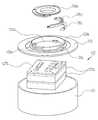
도 1은 본 발명의 다양한 실시예 중 하나에 따른 전자 장치(100)를 나타내는 사시도이다.1 is a perspective view illustrating an
도 1을 참조하면, 상기 전자 장치(100)는, 본체부(101)와, 상기 본체부(101)에 착탈가능하게 제공된 적어도 하나의 모듈부(102)를 포함할 수 있다. 본 실시예에서는, 상기 본체부(101)에 한 쌍의 모듈부(102)들이 결합 또는 연결된 구조가 각각 예시되고 있으나, 상기 본체부(101) 자체로서 개인용 컴퓨터(예: 데스크탑 PC, 노트북 PC) 등의 기능을 제공할 수 있으며, 상기 모듈부(102)(들)를 결합 또는 연결함으로써, 상기 전자 장치(100)의 기능이 확장되거나, 성능이 향상될 수 있다.Referring to FIG. 1, the
상기 본체부(101)는 상면과, 상면에 대면하는 하면, 상기 본체부(101)의 상면과 하면을 연결하는 측면을 포함하는 원통 형상을 가질 수 있다. 예컨대, 상기 본체부(101)의 상면과 하면은 원 형상이며, 상기 본체부(101)의 측면은 곡면으로 이루어질 수 있다. 예컨대, 상기 본체부(101)는 하면이 개방된 원통 형상의 제1 하우징(111)과, 상기 하우징(111)의 하면에 결합하여 상기 제1 하우징(111)을 폐쇄하는 제1 커버 부재(113)를 포함할 수 있다. 상기 제1 하우징(111)이 상기 본체부(101)의 상면과 측면을 제공하고, 상기 제1 커버 부재(113)가 상기 본체부(101)의 하면을 제공할 수 있다.The
상기 본체부(101)의 상면에는 스위치 부재(115)가 제공될 수 있다. 상기 스위치 부재(115)를 통해 사용자는 상기 전자 장치(100)의 전원을 온/오프(on/off)시킬 수 있다. 상기 본체부(101)의 측면에는 적어도 하나의 커넥터 부재(111a, 111b, 111c, 111d)가 배치(또는 노출)될 수 있다. 상기 본체부(101)의 측면으로 제공된 커넥터 부재들은 전원 커넥터(111a), 이어 잭(ear jack)(111b), High Definition Multimedia Interface(HDMI) 커넥터(111c), Universal Serial Bus(USB) 커넥터(111d), 저장 매체 소켓(111e; 도 3에 도시됨) 중 적어도 하나를 포함할 수 있다. 또한, 상기 본체부(101)는 통신 케이블(예: 랜(LAN) 케이블) 접속을 위한 커넥터 등 외부 장치 또는 네트워크에 접속하기 위한 수단으로서 도시되지 않은 다양한 커넥터를 더 포함할 수 있다. 상기 본체부(101)의 하면, 예컨대, 상기 제1 커버 부재(113)에는 상기 모듈부(102)(들)와의 결속, 결합을 위한 구조물이 제공될 수 있으며, 이는 도 4 등을 통해 더 상세하게 살펴보게 될 것이다.A
상기 모듈부(102)(들)는 배터리, 그래픽 모듈, 통신 모듈, 광학 모듈, 스토리지(storage) 모듈, 음향 모듈, 온/습도 센서 등 각종 센서가 탑재된 센서 모듈 중 하나 또는 둘 이상의 조합으로 이루어진 회로 장치들을 수용할 수 있다. 또한, 상기 모듈부(102)는 상술한 커넥터 부재(들) 또는 상기에서 언급되지 않은 또 다른 형태의 커넥터 부재(들)이 장착된 구성일 수 있다. 상기 모듈부(120)에 내장될 수 있는 회로 장치나 커넥터 부재들을 일부 예시하여 언급하였으나, 이는 본 발명의 상세한 설명을 간결하게 하기 위한 것이다. 예컨대, 본 발명의 다양한 실시예에 따른 전자 장치(100)의 모듈부(102)에 내장될 수 있는 회로 장치나 커넥터 부재들이 상기에서 나열한 것에 한정되지 않음에 유의한다.The module unit 102 (s) may be one or more of a combination of a battery, a graphic module, a communication module, an optical module, a storage module, an acoustic module, a temperature / Circuit devices. Further, the
상기에서 나열된 회로 장치나 커넥터 부재들이 각각 내장된 모듈부(102)들 중 사용자는 원하는 모듈부(102)를 선택, 구매하여 상기 본체부(101)와 결합할 수 있다. 또한, 사용자가 복수의 모듈부(102)를 구매하였다 하더라도, 필요에 따라 선택된 모듈부(102)를 상기 본체부(101)에 결합하여 상기 본체부(101)의 기능을 확장하거나 성능을 향상시킬 수 있다. 예를 들어, 사용자가 구매한 모듈부(102)들 중 제1의 모듈부는 배터리를 내장하고, 제2의 모듈부는 스토리지 모듈을 내장한다면, 사용자는 제1 모듈부를 상기 본체부(101)에 결합하여 상기 전자 장치(100)를 휴대하고 다니면서 사용할 수 있을 것이다. 사용자가 보유한 모듈부들 중에 광학 모듈, 예를 들어, 프로젝터와 스피커가 내장된 모듈부가 있다면, 이를 상기 본체부(101) 또는 상기 본체부(101)에 결합된 다른 모듈부에 결합할 수 있다. 따라서 사용자는 상기 본체부(101)에 결합한 모듈부의 기능에 따라 상기 전자 장치(100)만으로 각종 이미지 정보를 출력하거나 동영상을 감상하는 등 멀티미디어 기능을 편리하게 이용할 수 있다.The user can select and purchase the desired
상기 모듈부(102)는 상면과, 상면에 대면하는 하면, 상기 모듈부(102)의 상면과 하면을 연결하는 측면을 포함하는 원통 형상을 가질 수 있다. 예컨대, 상기 모듈부(102)의 상면과 하면은 원 형상이며, 상기 모듈부(102)의 측면은 곡면으로 이루어질 수 있다. 상기 모듈부(102)의 상면에는 상기 본체부(101)의 하면 또는 다른 모듈부의 하면에 결합할 수 있는 구조물이 제공될 수 있다. 예컨대, 상기 모듈부(102)는 상기 본체부(101)의 하면 또는 다른 모듈부의 하면에 결합할 수 있다. 상기 모듈부(102)는 상기 본체부(101) 등에 결속, 결합하기 위한 구조물을 포함할 수 있으며, 이에 대해서는 도 5를 통해 더 상세하게 살펴보게 될 것이다.The
본 발명의 구체적인 실시예에서, 상기 본체부(101)의 상면은 다른 구조물이 배치되지 않고 스위치 부재(115)가 배치된 구조를 예시하고 있지만, 상기 본체부(101)의 상면 또한 상기 모듈부(102)와 결합할 수 있는 구조물이 제공될 수 있다. 상기 본체부(101)의 상면에 제공되는 구조물은 상기 모듈부(102)의 상면에 제공된 구조물가 동일하게 구현될 수 있다. 또한, 본 발명의 구체적인 실시예에서는 상기 모듈부(102)가 상기 본체부(101) 또는 다른 모듈부에 결속, 결합함에 있어, 회전 방식으로 결속, 결합하는 구조를 예시하지만, 본 발명이 이에 한정되지는 않는다. 예를 들어, 스냅 핏(snap-fit) 구조, 자석식 결합 구조 또는 별도의 기계적인 결합 장치를 통해 상기 모듈부(102)가 상기 본체부(101)에 결속, 결합할 수 있다.The upper surface of the
도 2는 본 발명의 다양한 실시예 중 하나에 따른 전자 장치(100)에서 본체부(101)의 주요 구성을 나타내는 사시도이다. 도 3은 본 발명의 다양한 실시예 중 하나에 따른 전자 장치(100)에서 본체부(101)의 주요 구성을 나타내는 측면도이다.2 is a perspective view showing a main configuration of the
도 2와 도 3을 참조하면, 상기 본체부(101)는 상기 제1 하우징(111)의 내부로 배치된 적어도 하나의 회로 기판(101a, 101b)을 포함할 수 있다. 예를 들어, 프로세서, 저장 매체 등이 탑재된 제1 회로 기판(101a)과, 상술한 커넥터 부재(111a, 111b, 111c, 111d, 111e)들이 설치된 제2 회로 기판(101b)이 상기 제1 하우징(111)의 내부로 배치될 수 있다. 상기 커넥터 부재(111a, 111b, 111c, 111d, 111e)들은 상기 본체부(101)의 길이 방향(또는 높이 방향)을 따라 배열될 수 있으며, 상기 커넥터 부재(111a, 111b, 111c, 111d, 111e)들 중 일부(예: 상술한 저장 매체 소켓(111e))는 다른 커넥터 부재들과 다른 면에 배치될 수 있다.Referring to FIGS. 2 and 3, the
상기 제1 하우징(111)의 내부에 상기 회로 기판(101a, 101b)들을 지지, 고정하기 위해, 상기 본체부(101)는 고정 부재(113a, 113b)들을 포함할 수 있다. 예를 들어, 상기 제1 커버 부재(113)의 내측으로 두 쌍의 고정 부재(113a, 113b)들이 각각 제공되어 상기 제1, 제2 회로 기판(101a, 101b)의 하단, 양측 가장자리를 고정 지지할 수 있다. 상기 제1, 제2 회로 기판(101a, 101b)의 하단, 양측 가장자리는 상기 고정 부재(113a, 113b)들에 각각 삽입, 고정될 수 있으며, 도시되지 않은 가요성 인쇄회로 기판 등의 접속 수단을 통해 서로 연결될 수 있다. 또한, 상기 제1 및/또는 제2 회로 기판(101a, 101b)의 상단, 양측 가장자리 또한 제2의 고정 부재(113c)들에 각각 삽입, 고정될 수 있다. 상기 제2 고정 부재(113c)들은 상기 제1 하우징(111)의 내벽에 형성될 수 있다. 상기와 같은 고정 부재(113a, 113b, 113c)들의 형상과 배치는, 상기 제1 하우징(111)의 내부 공간이나, 상기 제1, 제2 회로 기판들(101a, 101b)의 형상 등을 고려하여 적절하게 설계될 수 있다.In order to support and fix the
도 4는 본 발명의 다양한 실시예 중 하나에 따른 전자 장치(100)의 본체부(101)에 제공된 결합 구조를 설명하기 위한 분리 사시도이다.4 is an exploded perspective view illustrating a coupling structure provided in the
도 4를 참조하면, 상기 본체부(101)의 하면, 예컨대, 상기 제1 커버 부재(113)에는 상기 모듈부(102)(들)와의 기계적인 결속, 결합을 위한 구조물뿐만 아니라 전기적인 연결을 위한 접속 구조가 제공될 수 있다. 본 실시예에서 상기 본체부(101)와 모듈부(102)의 전기적인 접속은 씨-클립(C-clip), 포고 핀(pogo pin)이나 접속 패드와 같은 물리적인 접촉 구조를 통해 이루어지는 구성이 개시된다. 하지만 본 발명이 이에 한정되지는 않으며, 무선 통신 방식으로 상기 본체부(101)와 모듈부(102) 사이에 데이터가 송수신될 수 있다. 이에 대해서는 도 15 등을 통해 상세하게 살펴보게 될 것이다.4, the lower surface of the
상기 본체부(101)는 상기 제1 커버 부재(113)의 외측면(예: 상기 본체부(101)의 하면)에 배치된 제1 결속 부재(133)를 포함할 수 있다. 상기 제1 결속 부재(133)는 가스켓(135)을 사이에 두고 상기 제1 커버 부재(113)의 외측면에 형성된 장착홈(131)에 장착될 수 있다. 상기 제1 결속 부재(133)는 중앙에 개구가 형성된 원판 형상으로서, 내주면에는 제1 결속 리브(133a)들이 형성될 수 있다. 상기 제1 결속 리브(133a)들은 상기 제1 결속 부재(133)의 내주면에서 원주 방향을 따라 서로 이격된 위치에 각각 배열될 수 있다. 상기 제1 결속 부재(133)를 상기 제1 커버 부재(113)에 고정함에 있어 스크루 등의 체결 수단이 활용될 수 있으며, 상기 가스켓(135)은 상기 제1 커버 부재(113)와 제1 결속 부재(133) 사이를 밀봉함으로써, 방진/방수 구조를 형성할 수 있다. 상기 제1 결속 부재(133), 예컨대, 상기 제1 결속 리브(133a)들은 상기 본체부(101)를 상기 모듈부(102)에 결속, 결합시키는 구조물로서 활용될 수 있다.The
상기 제1 커버 부재(113)의 내측면에는 가요성 인쇄회로 기판(137)과 제1 접속 단자(117)들이 원주 방향을 따라, 예컨대, 상기 모듈부(102)가 상기 본체부에 대하여 회전하는 방향을 따라 배열될 수 있다. 상기 제1 접속 단자(117)들은, 예를 들면, 씨-클립이나 포고 핀을 포함할 수 있으며, 상기 가요성 인쇄회로 기판(137)에 장착, 고정되어 상기 제1 커버 부재(113)의 내부에 위치하면서, 그 일부분이 상기 장착홈(131)으로 돌출될 수 있다. 상기 가요성 인쇄회로 기판(137)은 상기 하우징(111)의 내부에서 상기 제1, 제2 회로 기판(101a, 101b) 중 어느 하나에 연결될 수 있다. 상기 제1 커버 부재(113)의 내측면 상에는 지지 부재(139)가 제공되어 상기 가요성 인쇄회로 기판(137)의 일부분, 예를 들어, 상기 제1 접속 단자(117)들이 배열된 부분을 상기 제1 커버 부재(113)의 내측면에 밀착, 고정할 수 있다. 상기 지지 부재(139)가 배치됨으로써, 상기 제1 접속 단자(117)들이 상기 장착홈(131) 상에서 다른 물체와 간섭하더라도 상기 제1 접속 단자(117)들은 상기 제1 커버 부재(113) 상에 설치된 위치에서 안정적으로 고정될 수 있다. 상기 제1 접속 단자(117)들은 상기 모둘부(102)에 제공되는 제2 접속 단자(125; 도 6 등에 도시됨)들과 각각 접속(또는 접촉)하여, 상기 모듈부(102)를 상기 본체부(101)에 전기적으로 접속시키는 수단을 제공할 수 있다.The flexible printed
도 5는 본 발명의 다양한 실시예 중 하나에 따른 전자 장치(100)의 모듈부(102)들 중 하나를 예시하는 분리 사시도이다.5 is an exploded perspective view illustrating one of the
본 실시예를 설명함에 있어, 배터리가 내장된 모듈부를 예시하여 살펴보게 될 것이다. 하지만, 앞서 언급한 바와 같이, 본 발명의 다양한 실시예에 따른 전자 장치(100)는 복수의 모듈부들을 포함할 수 있으며, 각 모듈부에 내장된 회로 장치 등은 서로 다르게 구현될 수 있다. 따라서 사용자는 필요로 하는 기능이 탑재된 모듈부(들)를 구매하여 보유할 수 있으며, 실제로 상기 전자 장치(100)를 사용하고자 할 때 그 사용 목적에 따라 적절한 모듈부(들)를 선택하여 상기 본체부(101)에 장착할 수 있다.In explaining the present embodiment, a module unit with a built-in battery will be exemplified. However, as mentioned above, the
도 5를 참조하면, 상기 모듈부(102)는 제2의 하우징(121)과 제2의 커버 부재(123)를 포함할 수 있다. 상기 제2 하우징(121)의 내부에는 배터리(127a)가 내장되며, 상기 배터리(127a)로부터 출력되는 전원을 안정화하기 위한 회로 장치(127b)가 제공될 수 있다. 상기 제2 하우징(121)은 상면이 개방된 형상이며, 상기 제2 커버 부재(123)가 결합하여 상기 하우징(121)을 폐쇄할 수 있다. 상기 제2 커버 부재(123)에는 중앙부에서 상기 장착홈(131)에 상응하는 돌출부(123c)가 형성되며, 상기 돌출부(123c)의 외주면에 제2 결속 리브(123a)들이 형성될 수 있다. 상기 제2 결속 리브(123a)들은 상기 돌출부(123c)의 원주 방향을 따라 서로에 대하여 이격된 위치에 배치될 수 있다.Referring to FIG. 5, the
상기 제2 결속 리브(123a)들은 상기 제1 결속 리브(133a)들과 상응하게 배치되어 상기 모듈부(102)를 상기 본체부(101)에 결속, 결합시키는 수단을 제공할 수 있다. 예컨대, 상기 모듈부(102)의 어느 한 면(예: 상면)이 상기 본체부(101)의 어느 한 면(예: 하면)에 마주보게 결합할 때, 상기 제2 결속 리브(123a)들은 각각 상기 제1 결속 리브(133a)들 사이로 진입하여 상기 장착홈(131) 내에 위치할 수 있다. 상기 제2 결속 리브(123a)들이 상기 장착홈(131) 내에 위치된 상태에서, 사용자가 상기 본체부(101)에 대하여 상기 모듈부(102)를 회전시키면, 상기 제2 결속 리브(123a)가 상기 장착홈(131) 내에서 상기 제1 결속 리브(133a)와 마주보는 위치로 이동하여 상기 모듈부(102)를 상기 본체부(101)에 결속, 고정시킬 수 있다.The second
상기 돌출부(123c)의 내측으로 개구(123b)가 형성될 수 있는데, 상기 개구(123b)에는 제2의 지지 부재(125a)와 접속 부재(125b)가 배치될 수 있다. 상기 제2 지지 부재(125a)와 상기 접속 부재(125b)가 결합하여 원판 형상을 이루어 상기 개구(123b)에 장착될 수 있다. 예컨대, 상기 제2 지지 부재(125a)와 접속 부재(125b)가 결합한 상태로 장착되어 상기 개구(123b)를 폐쇄할 수 있다. 상기 접속 부재(125b)는 상기 회로 장치(127b)에 연결되는 가요성 인쇄회로 기판(125c)을 포함할 수 있으며, 상기 가요성 인쇄회로 기판(125c)은 상기 접속 부재(125b) 상에 배열된 제2 접속 단자들(125)(예: 접속 패드)과 연결될 수 있다. 다양한 실시예에 따르면, 상기 제2 접속 단자(125)들은 상기 가요성 인쇄회로 기판(125c)에 장착, 고정될 수 있으며, 상기 접속 부재(125b)의 상면으로 노출될 수 있다. 상기 제2 접속 단자(125)들은 상기 제1 접속 단자(117)들과 상응하게 배치되어, 상기 모듈부(102)를 상기 본체부(101)에 전기적으로 접속시킬 수 있다. 상기 제2 접속 단자(125)들의 배치와 상기 제2 접속 단자(125)들을 통한 접속 구조 등에 관해서는 도 6 등을 통해 더 상세하게 살펴보기로 한다.An
도 6 내지 도 9는 본 발명의 다양한 실시예 중 하나에 따른 전자 장치(100)의 본체부(101)와 모듈부(102)의 전기적인 접속 구조들을 각각 나타내는 도면이다.6 to 9 are views each showing the electrical connection structures of the
도 6과 도 7을 참조하면, 상기 모듈부(102)가 상기 본체부(101)에 결속, 결합하는 회전 방향(L)에서 제1 각도 지점(P1)에 위치했을 때, 상기 제2 접속 단자(125, 125D)들은 상기 제1 접속 단자(117)들 중 하나에 각각 접속(또는 접촉)할 수 있다. 상기 제2 접속 단자(125, 125D)들은 상기 모듈부(102)의 회전 방향을 따라 서로 일정한 간격으로 배열될 수 있으나, 어떤 실시예에서는, 상기 제2 접속 단자(125, 125D)들 중 하나, 예를 들면, 참조번호 '125D'로 지시된 제2 접속 단자가 배치된 간격은 다른 제2 접속 단자(125)들이 배열된 간격과 다를 수 있다. 참조번호 '125D'로 지시된 접속 단자는 상술한 제2 접속 단자들 중 하나에 해당하지만, 이하에서는 설명의 간결함을 위해 필요에 따라 '검출 단자'라 칭하기로 한다. 아울러, 도면의 참조번호를 병기하여 상기 검출 단자를 제2 접속 단자로 설명할 수 있음에 유의한다.6 and 7, when the
상기 제2 접속 단자(125)들은 상기 회전 방향(L) 또는 그 역방향(R)에서, 제2 각도 지점(P2)과 상기 제1 각도 지점(P1) 사이에서 상기 제1 접속 단자(117)들 중 하나에 각각 접속할 수 있다. 상기 모듈부(102)가 상기 제1, 제2 각도 지점(P1, P2) 사이에서 회전한다면, 상기 제2 접속 단자(125)들은 상기 제1 접속 단자(117)들과 미끄럼 접촉할 수 있다. 반면에, 상기 검출 단자(125D)는, 상기 모듈부(102)가 회전하여 상기 제1 각도 지점(P1)으로부터 이탈하면, 그에 상응하는 제1 접속 단자(117)로부터 이탈할 수 있다. 예컨대, 상기 제1 각도 지점(P1)으로부터 상기 모듈부(102)가 회전하여 이탈하면, 상기 검출 단자(125D)는 상기 제1 접속 단자(117)들 중 하나로부터 이탈하여 접속이 해제될 수 있다. 상기 검출 단자(125D)의 접속이 해제되더라도, 상기 모듈부(102)가 상기 제1, 제2 각도 지점(P1, P2) 사이에 위치하고 있다면, 상기 제2 접속 단자(125)들은 상기 제1 접속 단자(117)들과 접속된 상태를 유지할 수 있다. 상기 모듈부(102)가 회전하여 상기 제1, 제2 각도 지점(P1, P2) 사이의 각도 범위에서 벗어나면 상기 검출 단자(125D) 및 제2 접속 단자(125)들은 모두 상기 제1 접속 단자(117)들로부터 이탈할 수 있다. 상기 전자 장치(100)가 별도의 스토퍼 구조 등을 더 구비한다면, 상기 전자 장치(100)는 상기 제1 각도 지점(P1)에서 상기 모듈부(102)가 상기 회전 방향(L)으로 더 이상 회전하는 것을 제한할 수 있다.The
상기 제2 결속 리브(123a)들이 상기 장착홈(131)으로 진입할 때, 상기 검출 단자(125D) 및 제2 접속 단자(125)들은 상기 제1 접속 단자(117)들로부터 이탈한 위치(예: 상술한 제1, 제2 각도 지점(P1, P2) 사이의 각도 범위를 벗어난 위치)로 진입할 수 있다. 상기 제2 결속 리브(123a)들이 상기 장착홈(131)으로 진입한 상태에서, 상기 회전 방향(L)으로 상기 모듈부(102)를 회전하게 되면, 상기 제2 각도 지점(P2)에 이르러서 상기 제2 접속 단자(125)들은 각각에 상응하는 상기 제1 접속 단자(117)에 접촉할 수 있다. 하지만, 상기 제2 각도 지점(P2)에 이르더라도 상기 검출 단자(125D)는 아직 그에 상응하는 제1 접속 단자(117)로부터 이격된 지점에 위치할 수 있다. 상기 제2 각도 지점(P2)에서 상기 모듈부(102)가 상기 회전 방향(L)으로 더 회전하여 상기 제1 각도 지점(P1)에 이르면 상기 검출 단자(125D) 또한 그에 상응하는 제1 접속 단자(117)에 접촉할 수 있다. 앞서 언급한 바와 같이, 상기 모듈부(102)가 상기 제1, 제2 각도 지점(P1, P2) 사이에 위치하고 있다면, 상기 제2 접속 단자(125)들은 각각에 상응하는 제1 접속 단자(117)와 접촉된 상태를 유지할 수 있다.When the second
상기와 같은 제1, 제2 접속 단자(117, 125, 125D)들의 배치를 통해 상기 모듈부(102)로부터 상기 본체부(101)로 안정된 전원을 공급할 수 있다. 예를 들어, 배터리(127a)가 내장된 상기 모듈부(102)의 완전한 장착 여부를 상기 본체부(101)가 인지할 수 있게 하는 신호가 상기 검출 단자(125D)에 할당되고, 상기 제2 접속 단자(125)들 각각에 상기 본체부(101)로 전원을 공급하는 전원 라인이 할당될 수 있다. 따라서 전원 라인(예: 상기 제2 접속 단자(125)들)이 모두 상기 제1 접속 단자(117)들 중 하나에 각각 접속한 상태(예: 상기 제2 각도 지점(P2)에 위치한 상태)라 하더라도, 상기 검출 단자(125D)가 제1 접속 단자(117)에 연결되기 전까지 상기 전자 장치(100)는 상기 모듈부(102)로부터 상기 본체부(101)로 공급되는 전원을 차단할 수 있다. 예컨대, 상기 검출 단자(125D)를 통해 상기 모듈부(102)가 상기 본체부(101)와 완전히 결합된 상태(예: 상기 제1 각도 지점(P1)에 위치한 상태)를 나타내는 신호가 발생된 후, 상기 전자 장치(100)는 상기 모듈부(102)로부터 상기 본체부(101)로의 전원 공급을 허용할 수 있다.A stable power can be supplied from the
이상에서 살펴본 실시예에서는 4개의 제1 접속 단자(117)와 그에 상응하는 수의 제2 접속 단자(125, 125D)가 배치된 구성이 예시되고 있다. 하지만, 상기 본체부(101)와 모듈부(102) 간에 교환되는 신호(예: 전원 또는 데이터)의 양에 따라 상기 제1, 제2 접속 단자(117, 125, 125D)들의 수가 더 많아지거나 적어질 수 있다. 예컨대, 도 6과 도 7에 도시된 구조는 도면과 상세한 설명의 간결함을 위해 개략적으로 도시한 것이며, 본 발명이 이에 한정되지는 않는다.In the above embodiment, four
상기 제2 접속 단자(125)들에 전원 공급을 위한 라인이 각각 할당되고 그 수가 더 많다면, 상기 제1 각도 지점(P1)이 아닌 위치에서도 일부의 제2 접속 단자(125)들은 제1 접속 단자(117)들 중 하나에 접속할 수 있다. 예컨대, 상기 모듈부(102)의 회전 각도에 따라, 일부의 제2 접속 단자(125)들이 제1 접속 단자(117)들 중 하나에 연결되어 전원이 공급될 수 있다. 하지만, 상기 제2 접속 단자(125)들이 각각에 상응하게 설계된 제1 접속 단자가 아닌 다른 제1 접속 단자와 정렬, 접속한 상태에서 상기 본체부(101)로 전원이 공급되면, 이는 상기 본체부(101)로 공급되는 설계 전원과 달라질 수 있다. 예컨대, 상기 본체부(101)의 오작동이나 손상을 유발할 수 있다. 본 발명의 다양한 실시예에 따른 전자 장치(100)는, 상기와 같은 검출 단자(125D)를 배치함으로써, 제1 각도 지점(P1)이 아닌 다른 위치에서는 상기 모듈부(102)로부터 상기 본체부(101)로의 전원 공급을 차단함으로써, 안정된 전원을 상기 본체부(101)로 공급할 수 있다.If the number of lines for power supply to the
도 8을 참조하면, 본 발명의 다양한 실시예에 따른 전자 장치(100)에서, 제1, 제2 접속 단자(117, 125, 125D)들은 상기 본체부(101)의 하면과 상기 모듈부(102)의 상면 각각의 중심으로부터 측면을 향하는 방향을 따라, 예를 들면, 반지름 방향을 따라 배열될 수 있다. 아울러, 상기 제2 접속 단자(125, 125D)들 각각은 상기 모듈부(102)의 회전 방향을 따라 일정 각도 범위만큼 연장될 수 있으나, 상기 제2 접속 단자(125, 125D)들 중 하나는 다른 제2 접속 단자들보다 더 작은 각도 범위만큼 연장될 수 있다. 이하에서는 상기 모듈부(102)의 회전 방향에서 상기 제2 접속 단자(125, 125D)들 중 가장 작은 각도 범위만큼 연장된 제2 접속 단자를 '검출 단자(125D)'라 칭하기로 한다.Referring to FIG. 8, in the
상기 모듈부(102)는 반지름 방향으로 연장된 접속 부재(225b)를 포함할 수 있으며, 상기 제2 접속 단자(125)들과 검출 단자(125D)가 상기 접속 부재(225b) 상에서 상기 모듈부(102)의 상면(또는 하면)에서 반지름 방향을 따라 배열될 수 있다. 아울러, 복수의 상기 접속 부재(225b)들이 서로 이격된 상태에서 상기 모듈부(102)의 원주 방향을 따라 배열될 수 있다.The
상기 검출 단자(125D)는 상기 모듈부(102)의 측면에 인접하게 위치할 수 있다. 다만, 본 발명의 구성에서 상기 검출 단자(125D)의 위치는 이에 한정될 필요는 없다. 예컨대, 도 8에 도시된 바와 같이, 상기 제2 접속 단자(125)들이 상기 제1 접속 단자(117)들로부터 이탈한 위치에서, 상기 제1 접속 단자(117)로부터 가장 먼 각도 거리에 상기 검출 단자(125D)가 배치될 수 있다. 좀더 구체적으로 예를 들자면, 도 8에 도시된 위치로부터 상기 모듈부(102)가 10도 각도만큼 회전하여 상기 제2 접속 단자(125)들을 상기 제1 접속 단자(117)에 각각 접촉시킨다면, 10도보다 더 큰 각도(예: 13도 각도)만큼 회전한 후에 상기 검출 단자(125D)가 상기 제1 접속 단자(117)들 중 하나에 접촉할 수 있다.The detection terminal 125D may be positioned adjacent to the side surface of the
상기와 같은 검출 단자(125D) 및 제2 접속 단자(125)들을 배치함에 있어, 상기 제2 접속 단자(125)들이 상기 제1 접속 단자(117)들 중 하나에 각각 접속한 후 상기 검출 단자(125D)가 상기 제1 접속 단자(117)들 중 나머지 하나에 접속할 수 있다. 예컨대, 상기 검출 단자(125D)를 통해 상기 전자 장치(100)는 상기 모듈부(102)가 상기 본체부(101)에 완전히 접속된 상태를 검출할 수 있으며, 상기 검출 단자(125D)가 상기 제1 접속 단자(117)들 중 하나에 접속된 상태가 검출된 후에 상기 전자 장치(100)는 상기 모듈부(102)로부터 상기 본체부(101)로(또는 상기 본체부(101)로부터 상기 모듈부(102)로) 전원 또는 데이터 신호를 인가하도록 제어할 수 있다.The detection terminals 125D and the
도 6 내지 도 8을 참조하여 살펴본 바와 같이, 본 발명의 다양한 실시예에 따른 전자 장치(100)는 제1 접속 단자(117)들과 검출 단자를 포함하는 제2 접속 단자(125, 125D)들을 통해 본체부(101)와 모듈부(102)(들)을 전기적으로 접속시킬 수 있다. 다양한 실시예에 따르면, 모듈부(102)가 본체부(101)로 결합할 때 검출 단자(125D)는 다른 제2 접속 단자(125)들보다 늦게 제1 접속 단자(117)에 접속하고, 모듈부(102)가 본체부(101)로부터 이탈할 때 검출 단자(125D)가 다른 제2 접속 단자(125)들보다 먼저 제1 접속 단자(117)로부터 이탈할 수 있다. 이를 통해, 상술한 전자 장치(100)는 모듈부(102)의 접속/이탈 여부를 감지하여 본체부(101)와 모듈부(102) 간의 전원 또는 데이터 신호 교환을 적절한 시점에 허용 또는 차단할 수 있다.6 to 8, the
도 9를 참조하면, 상기 제1, 제2 접속 단자(117, 125)들은 상기 모듈부(102)의 회전 방향(L)에 대하여 경사지게 형성된 영역, 예를 들면, 경사면(I1, I2)(들)에 각각 배치될 수 있다. 상기 모듈부(102)가 상기 본체부(101)에 결속하는 방향으로 회전하면 상기 경사면(I1, I2)들이 서로 근접하게 이동하고, 상기 모듈부(102)가 상기 본체부(101)로부터 이탈하는 방향으로 회전하면 상기 경사면(I1, I2)들이 서로 멀어지게 이동할 수 있다. 예컨대, 상기 모듈부(102)가 상기 본체부(101)에 완전히 결합한 상태에서, 상기 제2 접속 단자(125)들이 상기 제1 접속 단자(117)들에 각각 접속할 수 있다. 상기 모듈부(102)가 상기 본체부(101)로부터 이탈하는 방향으로 회전하면, 선행 실시예들과 다르게, 상기 제2 접속 단자(125)들은, 상기 제1 접속 단자(117)들과 미끄럼 접촉하지 않고 상기 제1 접속 단자(117)들로부터 멀어지는 방향으로 이탈할 수 있다.9, the first and
상기 본체부(101)와 모듈부(102)가 완전히 결합한 상태에서 상기 모듈부(102)의 회전 방향(L)에 대하여 경사진 면들(예: 상기 경사면(I1, I2)들)이 서로 대면하게 접촉하고 있으므로, 상기 본체부(101)로부터 이탈하는 방향으로 회전시키는 힘이 상기 모듈부(102)에 작용할 수 있다. 이는 상기 본체부(101)와 모듈부(101)의 안정된 접속에 장애가 될 수 있는 바, 본 실시예에 따른 전자 장치는 스토퍼 장치를 더 포함함으로써, 상기 본체부(101)와 모듈부(102) 사이의 안정된 접속을 유지할 수 있다.(For example, the inclined surfaces I1 and I2) with respect to the rotational direction L of the
상기 스토퍼 장치는 상기 본체부(101)에 수용된 스토퍼 부재(141)와 탄성 부재(143), 상기 모듈부(102)에 형성된 스토퍼 홈(145)을 포함할 수 있다. 상기 스토퍼 부재(141)는 상기 탄성 부재(143)의 지지를 받이 일부분을 상기 본체부(101)의 일면(예: 하면)으로 돌출시킬 수 있다. 상기 모듈부(102)가 상기 본체부(101)에 결합하는 방향으로 회전하여 상기 제1, 제2 접속 단자(117, 125)들이 서로 접속된 때, 상기 스토퍼 부재(141)는 상기 스토퍼 홈(145)에 맞물릴 수 있다. 예컨대, 상기 탄성 부재(143)의 탄성력을 제공받는 상기 스토퍼 부재(141)가 상기 스토퍼 홈(145)에 맞물려 상기 본체부(101) 상에서 일정 각도 지점에 상기 모듈부(102)를 고정할 수 있다. 따라서 상기 경사면(I1, I2)들에 상기 제1, 제2 접속 단자(117, 125)들이 각각 배치되더라도 상기 제1, 제2 접속 단자(117, 125)들은 안정된 접속 상태를 유지할 수 있다.The stopper device may include a
본 실시예에 따른 전자 장치는, 상기 제1, 제2 접속 단자(117, 125)들을 경사면(I1, I2)(들)에 각각 배치함으로써, 상기 모듈부(102)의 회전 과정에서 상기 본체부(101)나 모듈부(102)의 다른 부분과 마찰(예: 미끄럼 접촉)하는 것을 방지할 수 있다. 또한, 본 실시예에 따른 전자 장치는 스토퍼 장치를 이용하여 상기 모듈부(102)를 일정 각도 지점에 고정함으로써, 상기 제1, 제2 접속 단자(117, 125)들을 경사면(I1, I2)(들)에 배치하면서도 안정된 접속 상태를 유지할 수 있다.The electronic device according to the present embodiment is characterized in that the first and
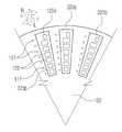
도 10은 본 발명의 다양한 실시예 중 다른 하나에 따른 전자 장치(100)에서 본체부의 주요 구성을 나타내는 사시도이다. 도 11은 본 발명의 다양한 실시예 중 다른 하나에 따른 전자 장치(100)에서 본체부의 주요 구성을 나타내는 평면도이다.10 is a perspective view showing a main configuration of a main body portion in an
도 10과 도 11을 참조하면, 본 실시예에 따른 전자 장치(100)는 커넥터 부재(111a, 111b, 111c, 111d, 111e)들 중 적어도 일부는 상기 제1 하우징(111)의 원주 방향을 따라 배열될 수 있다. 상기 커넥터 부재(111a, 111b, 111c, 111d, 111e)들을 원주 방향을 따라 배열함에 있어, 상기 전자 장치(100)는 상기본체부(101)에 내장된 제3의 회로 기판(101c)을 더 포함할 수 있다. 상기 제3 회로 기판(101c)은 상술한 제1, 제2 회로 기판(101a, 101b)에 대하여 수직 방향으로 배치될 수 있으며, 상기 제1 하우징(111)의 내부 공간의 형상에 부합하는 부채꼴 형상(또는 반원 형상)의 평판 형태를 가질 수 있다. 상술한 커넥터 부재(111a, 111b, 111c, 111d, 111e)들 중 적어도 일부가 상기 제3 회로 기판(101c)의 원주 방향을 따라 배열될 수 있다.10 and 11, the
도시되지는 않지만, 상기 제1, 제2, 제3 회로 기판(101a, 101b, 101c)은 가요성 인쇄회로 기판 등 별도의 접속 수단을 통해 서로 연결될 수 있다. 다양한 실시예에 따르면, 상기 제3 회로 기판(101c)에 다수의 접속 핀들이 배치된 소켓(미도시)이 제공될 수 있으며, 상기 제1, 제2 회로 기판(101a, 101b)이 각각 상기 소켓에 삽입되어 전기적으로 접속될 수 있다. 상기 커넥터 부재(111a, 111b, 111c, 111d, 111e)들은 각각의 크기와 형상에 따라 또는 상기 제1 하우징(111)의 내부 공간에 따라 적절한 위치에 배치될 수 있으며, 본 발명이 도 10 또는 도 11에 도시된 배치 구조에 한정되지 않음에 유의한다.Although not shown, the first, second, and
이상의 상술한 실시예에 따른 전자 장치(100)는, 하나의 본체부(101)와 하나 또는 두개의 모듈부(102)를 구비하는 구성을 예시하였으나, 더 많은 수의 모듈부(102)가 상기 본체부(101) 또는 다른 모듈부(102)에 결합할 수 있다. 상기 본체부(101)에 직접적으로 결합하거나 간접적으로 결합하는 모듈부(102)(예: 다른 모듈부를 통해 본체부와 전기적으로 접속하는 모듈부)에 탑재된 기능에 따라 사용자는 상기 전자 장치(100)의 성능이나 기능을 다양화할 수 있다. 이러한 구성에 대하여 도 12를 통해 살펴보기로 한다.Although the
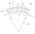
도 12는 본 발명의 다양한 실시예에 따른 전자 장치(200)의 활용 예들을 설명하기 위한 도면이다.12 is a diagram for explaining utilization examples of an
본 실시예에 따른 전자 장치(200)는 복수의 모듈부(102a, 102b, 102c)들을 포함하며, 이하의 상세한 설명에서는 상기 모듈부들을 '제1 모듈부(102a)', '제2 모듈부(102b)', '제3 모듈부(102c)'로 구분하여 설명할 수 있다. 하지만 이는 설명의 간결함을 위한 것일 뿐, 이러한 구분 또는 본 실시예에서 예시하는 모듈부들의 수 등이 본 발명을 한정하지 않음에 유의한다.The
도 12를 참조하면, 상기 전자 장치(200)는 상기 본체부(101)에 전기적으로 연결되는 복수의 모듈부(102a, 102b, 102c)들을 포함할 수 있다. 상기 모듈부(102a, 102b, 102c)들은 상기 본체부(101)에 직접 결속되거나 또는 상기 본체부(101)에 결합한 다른 모듈부에 결속됨으로써 상기 본체부(101)와 전기적으로 연결될 수 있다. 상기 본체부(101) 및 모듈부(102a, 102b, 102c)들은 각각 상면과 하면 중 적어도 하나에 상술한 결속 부재들과 접속 부재들이 배치되어 서로 기계적으로 또는 전기적으로 결합, 접속될 수 있다.Referring to FIG. 12, the
상기 본체부(101)와 모듈부(102a, 102b, 102c)들은 각각이 원통 형상이면서, 서로 결합한 상태에서도 원통 형상을 이룰 수 있다. 다만, 본 발명이 이에 한정될 필요는 없다. 예를 들어, 상기 본체부(101)와 모듈부(102a, 102b, 102c)들이 각각 직육면체 형상이면서, 상기 본체부(101)의 하면과 모듈부(102a, 102b, 102c)의 상면이 서로 대면하게 결속, 결합할 수 있다. 상기 본체부(101)와 모듈부(102a, 102b, 102c)들이 각각 직육면체 형상인 경우, 상기 본체부(101)와 모듈부(102a, 102b, 102c)(들)가 서로 결속, 결합한 상태에서 상기 본체부(101)의 한 측면은 그에 인접하는 상기 모듈부(102a, 102b, 102c)(들)의 한 측면과 동일 평면을 이룰 수 있다.The
상기 전자 장치(200)는, 배터리가 내장된 제1의 모듈부(102a), 그래픽 모듈이나 보조 저장 장치가 내장된 제2의 모듈부(102b), 음향 모듈 또는 광학 모듈이 내장된 제3의 모듈부(102c)를 포함할 수 있다. 상기 제1, 제2, 제3 모듈부(102a, 102b, 102c)에 각각 내장된 회로 장치들은 예시된 실시예와 다르게 조합되어 새로운 제4의 모듈부를 구성할 수 있다. 다양한 실시예에 따르면, 상기 제1, 제2 , 제3 모듈부(102a, 102b, 102c) 각각에 내장되는 상술한 회로 장치들 외에도 다양한 안테나 장치나 각종 센서(예: 온/습도 센서, 근조도 센서, 생체신호 감지 센서 등)이 탑재된 제5, 제6의 모듈부가 구현될 수도 있다. 사용자는 이러한 다양한 모듈부들 중, 필요한 모듈부(들)를 선택, 구매하여 보유할 수 있다. 또한, 사용자는 보유하고 있는 모듈부들 중에서 상기 전자 장치(200)의 사용 목적에 따라 원하는 모듈부(들)를 선택하여 상기 본체부(101)에 장착할 수 있다. 예컨대, 사용자가 의도하는 바에 따라 상기 전자 장치(200)를 다양한 용도로 활용할 수 있다. 또한, 상기 전자 장치(200)는 상기 본체부(101)에 탑재된 회로 장치들 중 적어도 하나와 동등한 회로 장치, 예를 들면, 프로세서를 내장한 모듈부를 포함할 수 있다. 상기 본체부(101)와 동등한 회로 장치를 내장한 모듈부를 탑재한 모듈부가 상기 본체부(101)에 연결되면, 상기 전자 장치(200)는 더 높은 성능(예: 상기 본체부(101) 하나만으로 작동할 때의 성능보다 더 높은 성능)을 발휘할 수 있다.The
상기 본체부(101)는, 프로세서, 통신 모듈, 저장 장치를 포함함으로써 그 자체로서 데스크탑 PC 또는 노트북 PC 등의 전자 장치와 동등한 기능을 제공할 수 있다. 상기 본체부(101)를 통해 데스크탑 PC 또는 노트북 PC 등의 전자 장치와 동등한 기능을 활용함에 있어, 상기 커넥터 부재(111a, 111b, 111c, 111d, 111e)들은 키보드나 마우스 등의 입력 장치, 디스플레이 장치 등의 출력 장치와 접속할 수 있는 수단을 제공할 수 있다. 상기 커넥터 부재(111a, 111b, 111c, 111d, 111e)들 중 적어도 하나는 전원 커넥터로 할당되어, 상기 본체부(101)는 상기 커넥터 부재들 중 하나를 통해 전원을 공급받을 수 있다.The
앞서 언급한 바와 같이, 상기 제1 모듈부(102a)는 배터리를 내장할 수 있다. 예컨대, 상기 본체부(101)는 상기 제1 모듈부(102a)로부터 전원을 공급받아 작동할 수 있다. 상기 전자 장치(200)가 상기 본체부(101)에 착탈 가능한 제1 모듈부(102a)를 포함함으로써, 사용자는 상기 전자 장치(200)를 휴대하고 다니면서 원하는 장소에서 편리하게 사용할 수 있다.As described above, the
상기 제2 모듈부(102b)는 그래픽 모듈이나 보조 저장 장치를 포함할 수 있다. 예컨대, 상기 제2 모듈부(102b)가 상기 본체부(101)에 또는 상기 본체부(101)에 결합된 다른 모듈부에 결합함으로써 상기 전자 장치(200)의 그래픽 성능을 향상시키거나 데이터 저장 용량을 확장할 수 있다.The
상기 제3 모듈부(102c)는 음향 모듈 또는 광학 모듈이 내장되어, 상기 전자 장치(200) 자체의 입출력 장치를 확장할 수 있다. 예컨대, 상기 제3 모듈부(102c)에 내장된 음향 모듈은 고음질 마이크로 폰이나 스피커 폰을 포함함으로써, 상기 전자 장치(200)로 입출력되는 음향의 품질을 향상시킬 수 있다. 상기 제3 모듈부(102c)에 내장된 광학 모듈은 카메라 또는 프로젝터를 포함할 수 있으며, 상기 전자 장치(200)는 상기 제3 모듈부(102c)의 광학 모듈을 이용하여 동영상을 촬영하거나 상기 본체부(101)(또는 상기 제2 모듈부(102b))를 통해 생성된 화면을 출력할 수 있다. 상기 제3 모듈부(102c)가 음향 모듈이나 광학 모듈을 포함한 경우, 상기 제3 모듈부(102c)는 블루투스(Blutooth) 등의 무선 통신 방식으로 상기 본체부(101) 또는 다른 전자 장치와 연결될 수 있다. 예컨대, 상기 제3 모듈부(102c)는 그 자체로서 다른 전자 장치와 조합되어 고품질 음향의 입출력 기능을 제공할 수 있다.The
본 실시예에서, 상기 제2, 제3 모듈부(102b, 102c)가 상기 본체부(101)에 각각 직접 결합하고, 상기 제1 모듈부(102a)는 상기 제2 모듈부(102b)를 통해 상기 본체부(101)에 연결된 구성이 예시되고 있으나, 본 발명이 이에 한정될 필요는 없다. 예컨대, 상기 제1, 제2, 제3 모듈부(102a, 102b, 102c)를 상기 본체부(101)에 또는 다른 모듈부에 각각 결합하는 순서나 배치는 사용자의 의도에 따라 다양하게 구현될 수 있다.In the present embodiment, the second and
도 13 내지 도 16은 본 발명의 다양한 실시예에 따른 전자 장치(200)에서, 본체부(101)와 모듈부(102a, 102b, 102c)들 간의 접속 구조를 각각 예시하는 도면이다.13 to 16 are views illustrating the connection structure between the
도 13과 도 14를 참조하면, 상기 본체부(101)와 모듈부(102a, 102b)들 간에는 상술한 제1, 제2 접속 단자(117, 125, 125D)들의 구조를 통해 서로 전기적으로 접속할 수 있다. 또한, 복수의 모듈부들이 상기 본체부(101)와 연결되는 경우, 하나의 모듈부는 다른 모듈부를 통해 상기 본체부(101)와 전기적으로 연결될 수 있다. 예컨대, 상기 모듈부(102a, 102b)들은 각각 다른 모듈부를 상기 본체부(101)로 연결하기 위한 접속 경로를 제공할 수 있다.13 and 14, the
도 13은 상기 제2 모듈부(102b)가 상기 본체부(101)에 직접 결합하고, 상기 제1 모듈부(102a)가 상기 제2 모듈부(102b)에 결합하여 상기 제2 모듈부(102b)를 통해 상기 본체부(101)에 전기적으로 연결된 구조를 예시하고 있다. 도 14는 상기 제1 모듈부(102a)가 상기 본체부(101)에 직접 결합하고, 상기 제2 모듈부(102b)가 상기 제1 모듈부(102a)에 결합하여 상기 제1 모듈부(102a)를 통해 상기 본체부(101)에 전기적으로 연결된 구조를 예시하고 있다.13 shows a state in which the
상기 본체부(101)는 상기 제1 또는 제2 모듈부(102a, 102b)와의 접속을 위한 제1 접속 단자들을 포함하는데, 상기 제1 접속 단자들은 제1 전원 단자(215a)와 제1 데이터 신호 단자(215b)들을 포함할 수 있다. 상기 제1, 제2 모듈부(102a, 102b)는 서로 간의 접속을 위한 또는 상기 본체부(101)와의 접속을 위한 제2 접속 단자들을 각각 포함하는데, 상기 제2 접속 단자들은 제2 전원 단자(217a, 219a)들과 제2 데이터 신호 단자(217b, 219b)들을 포함할 수 있다.The
상기 제2 모듈부(102b)가 상기 본체부(101)에 결합한 경우, 상기 제1 모듈부(102a)는 그의 제2 전원 단자(217a)들이 상기 제2 모듈부(201b)의 제2 전원 단자(219b)들을 통해 상기 본체부(101)로 접속하여 상기 본체부(101)에 전원을 공급할 수 있다. 상기 제2 모듈부(102b)는 제2 데이터 신호 단자(219b)들을 통해 상기 본체부(101)로 접속하여 그래픽 신호 등을 교환할 수 있다.When the
상기 제1 모듈부(102a)가 상기 본체부(101)에 결합한 경우, 상기 제1 모듈부(102a)는 그의 제2 전원 단자(217a)가 상기 제1 전원 단자(215a)와 접속하여 상기 본체부(101)로 전원을 공급할 수 있다. 상기 제2 모듈부(102b)는 상기 제1 모듈부(102a)를 통해 상기 본체부(101)와 전기적으로 연결될 수 있다. 예컨대, 상기 제2 모듈부(102b)의 제2 데이터 신호 단자(219b)들이 상기 제1 모듈부(102a)의 제2 데이터 신호 단자(217b)들을 통해 상기 본체부(101)의 제1 데이터 신호 단자(215b)들과 연결될 수 있다.When the
이와 같이, 상기 제1, 제2 모듈부(102a, 102b)들은 상기 본체부(101)와 또는 다른 모듈부와 전기적으로 접속하여 전원이나 데이터 신호를 교환할 수 있다.In this way, the first and
도 15와 도 16은 상기 본체부(101)와 모듈부(102a, 102b, 102c)들 중 하나 사이에 또는 상기 모듈부(102a, 102b, 102c)들 상호간에 무선으로 전원이나 데이터 신호를 교환하는 구조를 예시하고 있다. 설명의 간결함을 위해 선행 실시예에서는 접속 단자들의 직접적인 접촉 방식으로 전원이나 데이터 신호가 교환되는 구조를, 이하의 실시예에서는 무선 방식으로 전원이나 데이터 신호가 교환되는 구조를 각각 예시하고 있지만, 본 발명이 이에 한정되지는 않는다. 예를 들어, 전원 공급은 접속 단자들의 직접적인 접촉 방식으로, 음향이나 그래픽 등의 데이터 신호는 무선 방식으로 각각 교환될 수 있다. 또한, 본 발명의 구체적인 실시예에서 개시하지는 않지만, 본 발명의 다양한 실시예에 따른 전자 장치에서, 광통신 방식 등 다른 형태의 전원 또는 데이터 신호 교환 방식들을 통해 본체부와 모듈부(들) 간의 접속이 구현될 수 있다.15 and 16 are diagrams for explaining a method of exchanging power or data signals wirelessly between the
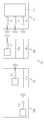
도 15와 도 16을 참조하면, 상기 전자 장치(200)에서, 상기 본체부(101)는 복수의 무선 통신 채널(C1, C2, C3)을 구비함으로써, 무선 통신 방식, 예를 들면, 블루투스(Blutooth)나 와이기그(Wireless Gigagit Alliance; WiGig) 등의 통신 규격을 통해 상기 모듈부(102a, 102b, 102c)들과 전원 또는 데이터 신호를 교환할 수 있다. 상기 무선 통신 채널(C1, C2, C3)들은 각각 상기 본체부(101)에 내장된 회로 장치, 예컨대, 상술한 제1 회로 기판(101a)에 탑재된 통신 모듈이나 프로세서 등에 연결될 수 있다. 상기 본체부(101)가 가진 무선 통신 채널의 수에 따라 상기 본체부(101)에 직접적으로 또는 간접적으로(예: 다른 모듈부를 통해) 데이터 신호를 교환할 수 있는 모듈부들의 수가 설정될 수 있다. 다만, 앞서 언급한 바와 같이, 상기 본체부(101)가 무선 통신 채널 외에 상술한 접속 단자들을 포함한다면, 무선 통신 채널의 수보다 더 많은 수의 모듈부들이 상기 본체부(101)와 접속할 수 있다.15 and 16, in the
상기 모듈부(102a, 102b, 102c)들은 각각 상기 본체부(101) 또는 다른 모듈부와의 무선 통신을 수행는 접속 채널C3a, C3b, C3c)을 포함할 수 있다. 또한, 상기 모듈부(102a, 102b, 102c)들은 각각 상기 본체부(101)와 다른 모듈부의 무선 통신을 중계하는 전달 채널(TR1b, TR1c, TR2c)을 포함할 수 있다. 예를 들어, 상기 모듈부들 중 제1 모듈부(102a)는 상기 본체부(101) 또는 다른 모듈부와의 무선 통신을 수행는 접속 채널(C3a)을 포함함으로써, 직접적으로 또는, 제2, 제3 모듈부(102b, 102c)들을 통해 간접적으로 상기 본체부(101)와 데이터 신호를 교환할 수 있다. 예컨대, 상기 제2, 제3 모듈부(102b, 102c)는 각각 상기 본체부(101)와 제1 모듈부(102b) 사이의 무선 데이터 신호를 중계하는 전달 채널(TR1b, TR1c)을 포함할 수 있다. 이로써 상기 제1 모듈부(102a)는 상기 본체부(101)에 직접 결합하거나 상기 제2 및/또는 제3 모듈부(102b, 102c)를 통해 상기 본체부(101)에 연결되어 상기 본체부(101)와 데이터 신호를 교환할 수 있다.The
상기 제2 모듈부(102b)는 상기 본체부(101) 또는 다른 모듈부와의 무선 통신을 수행하는 접속 채널(C3b)과, 상기 본체부(101)나 제3 모듈부(102c)와 다른 모듈부(예: 상기 제1 모듈부(102a)) 사이에서 데이터 신호를 중계하는 전달 채널(예: 상기 전달 채널(TR1b))을 포함할 수 있다. 상기 제2 모듈부(102b)는 직접적으로 또는, 상기 제3 모듈부(102c)를 통해 간접적으로 상기 본체부(101)와 데이터 신호를 교환할 수 있다. 예컨대, 상기 제3 모듈부(102c)는 상기 본체부(101)와 제2 모듈부(102b) 사이의 무선 데이터 신호를 중계하는 제2의 전달 채널(TR2c)을 포함할 수 있다. 이로써 상기 제2 모듈부(102b)는 상기 본체부(101)에 직접 결합하거나 상기 제3 모듈부(102c)를 통해 상기 본체부(101)에 연결되어 상기 본체부(101)와 데이터 신호를 교환하면서, 상기 본체부(101) 및/또는 제3 모듈부(102c)와 상기 제1 모듈부(102a) 사이에서 무선 데이터 신호를 중계할 수 있다.The
상기 제3 모듈부(102c)는 상기 본체부(101)와의 무선 통신을 수행하는 접속 채널(C3c)과, 상기 본체부(101)와 다른 모듈부들(예: 상기 제1, 제2 모듈부(102a, 102b)) 사이에서 신호를 중계하는 전달 채널들(예: 상기 전달 채널(TR1c) 및 제2 전달 채널(TR2c))을 포함할 수 있다. 예컨대, 상기 제3 모듈부(102c)는 상기 본체부(101)에 직접 결합하여 상기 본체부(101)와 무선 통신 방식으로 데이터 신호를 교환하면서, 상기 본체부(101)와 상기 제1 및/또는 제2 모듈부(102a, 102b) 사이에서 무선 데이터 신호를 중계할 수 있다.The
다양한 실시예에 따르면, 상기 전자 장치(200)는 또 다른 모듈부, 예컨대, 상기 본체부(101)와 제3 모듈부(102c) 사이에서 무선 데이터 신호를 중계하는 전달 채널을 포함하는 제4의 모듈부를 더 포함할 수 있다. 이로써 상기 제3 모듈부(102c)는 제4의 모듈부를 통해 상기 본체부(101)에 연결될 수 있으며, 제4의 모듈부에 제공된 전달 채널을 통해 상기 본체부(101)와 무선 방식으로 데이터 신호를 교환할 수 있다. 상기와 같은 제4 모듈부는 상기 제1 및/또는 제2 모듈부(102a, 102b)와 상기 본체부(101) 사이에 무선 신호를 중계하는 전달 채널들을 더 포함할 수 있다.According to various embodiments, the
다양한 실시예에 따르면, 상술한 전달 채널(TR1b, TR1c, TR2c)들은 전송 선로 또는, 증폭기나 변조기, 각종 필터 등이 탑재된 회로 장치를 포함할 수 있다. 또한, 상기 전달 채널(TR1b, TR1c, TR2c)들은, 도 16에 도시된 바와 같이, 관통홀 형태로 구현될 수 있다. 예컨대, 상기 제2 및/또는 제3 모듈부(102b, 102c)는 상기 본체부(101) 측에 제공된 안테나와 상기 제1 모듈부(102b) 측에 제공된 안테나 사이에 무선 신호가 진행될 수 있는 경로 또는 공간을 제공하는 관통홀들 포함함으로써 전달 채널이 구현될 수 있다.According to various embodiments, the above-described transmission channels TR1b, TR1c, and TR2c may include a transmission line, a circuit device on which an amplifier, a modulator, various filters, and the like are mounted. In addition, the transmission channels TR1b, TR1c, and TR2c may be implemented as through holes as shown in FIG. For example, the second and / or
상기와 같은 전자 장치(200)는, 본체부와 모듈부들 간의 무선 통신을 구현함에 있어, 각각의 모듈부들이 서로 다른 수의 전달 채널(들)을 포함할 수 있다. 예컨대, 복수의 모듈부들을 직렬로 연결하여 본체부에 결합하되, 그 결합 순서를 설정하여 필요한 수의 전달 채널(들)을 각 모듈부에 형성함으로써, 그 구조를 단순화할 수 있다. 또한, 각 모듈부(들)는 본체부의 무선 통신 채널들 중 하나에 각각 접속할 수 있는 접속 채널이 포함된 바, 각각이 독립적으로 본체부에 직접 결합하여 본체부와 데이터 신호를 교환할 수 있다.
The above-described
상술한 바와 같이, 본 발명의 다양한 실시예에 따른 전자 장치는, 제1의 상면과, 상기 제1 상면에 대향하는 제1의 하면과, 상기 제1 상면과 제1 하면을 연결하는 제1 측면을 포함하는 본체부; 및 제2의 상면과, 상기 제2 상면에 대향하는 제2의 하면과, 상기 제2 상면과 제2 하면을 연결하는 제2 측면을 각각 포함하는 적어도 하나의 모듈부를 포함할 수 있으며,As described above, the electronic device according to various embodiments of the present invention includes a first upper surface, a first lower surface opposed to the first upper surface, and a second lower surface that connects the first upper surface and the first lower surface, A main body portion including a main body portion; And at least one module portion including a second upper surface, a second lower surface opposite to the second upper surface, and a second side connecting the second upper surface and the second lower surface,
상기 모듈부는, 상기 제2 상면, 제2 하면 및 제2 측면 중 하나가 상기 제1 상면, 제1 하면 및 제1 측면 중 하나에 대면한 상태로 상기 본체부와 또는 다른 모듈부와 착탈 가능하게 제공될 수 있고, 상기 본체부에 장착된 모듈부는 상기 본체부와 전기적으로 연결될 수 있다.The module unit may be configured such that one of the second top surface, the second bottom surface, and the second side is detachably attached to the main body unit or another module unit while facing one of the first top surface, the first bottom surface, and the first side surface And the module part mounted on the main body part can be electrically connected to the main body part.
다양한 실시예에 따르면, 상기 본체부와 모듈부는 상기 제1, 제2 측면이 각각 곡면으로 이루어진 원통 형상(cylindrical shape)일 수 있다.According to various embodiments, the body portion and the module portion may have a cylindrical shape in which the first and second side surfaces are respectively curved.
다양한 실시예에 따르면, 상기 모듈부들은 상기 제2 상면 또는 제2 하면이 상기 제1 하면 또는 제1 상면에 대면하게 접촉한 상태로 회전하여 상기 본체부와 결합함으로써 원통 형상을 형성할 수 있다.According to various embodiments, the module portions may rotate in a state in which the second upper surface or the second lower surface is in contact with the first lower surface or the first upper surface to be in contact with the main body portion, thereby forming a cylindrical shape.
다양한 실시예에 따르면, 상기 전자 장치는, 상기 제1 상면 또는 제1 하면에 제공된 제1 접속 단자들; 및 상기 제2 상면 또는 제2 하면에 제공된 제2 접속 단자들을 포함할 수 있으며, 상기 모듈부가 상기 본체부와 결합한 상태에서, 상기 제2 접속 단자들이 상기 제1 접속 단자들 중 하나에 각각 접속할 수 있다.According to various embodiments, the electronic device further includes: first connection terminals provided on the first upper surface or the first lower surface; And a second connection terminal provided on the second upper surface or the second lower surface, wherein the second connection terminals can be respectively connected to one of the first connection terminals, have.
다양한 실시예에 따르면, 상기 제1, 제2 접속 단자들은 각각 상기 모듈부의 회전 방향을 따라 배열될 수 있다.According to various embodiments, the first and second connection terminals may be arranged along the rotational direction of the module unit, respectively.
다양한 실시예에 따르면, 상기 제1, 제2 접속 단자들이 각각 배열된 영역들은 각각 상기 모듈부의 회전 방향에 대하여 경사지게 형성될 수 있으며, 상기 모듈부가 상기 본체부와 결합하는 방향으로 회전할 때, 상기 영역들이 서로에게 접근할 수 있다.According to various embodiments, the regions where the first and second connection terminals are respectively arranged may be formed to be inclined with respect to the rotational direction of the module portion, and when the module portion rotates in a direction to engage with the main body portion, Areas can access each other.
다양한 실시예에 따르면, 상기 제1, 제2 접속 단자들 각각은 상기 제1 상면, 제1 하면, 제2 상면 및 제2 하면 중 어느 하나의 중심으로부터 상기 제1 또는 제2 측면을 향하는 방향을 따라 배열될 수 있다.According to various embodiments, each of the first and second connection terminals may have a direction from the center of the first top surface, the first bottom surface, the second top surface, and the second bottom surface toward the first or second side surface .
다양한 실시예에 따르면, 상기 제2 접속 단자들 중 하나(이하, '검출 단자')는 상기 모듈부가 상기 본체부로 결합하는 회전방향의 제1 각도 지점에서 상기 제1 접속 단자들 중 하나에 접속할 수 있으며, 상기 제2 접속 단자들 중 나머지는 상기 모듈부가 상기 본체부로 결합하는 회전방향의 역방향에서 상기 제1 각도 지점으로부터 제2 각도 지점 사이에서 상기 제1 접속 단자들 중 나머지와 각각 접속할 수 있다.According to various embodiments, one of the second connection terminals (hereinafter 'detection terminal') can be connected to one of the first connection terminals at a first angle point in the rotational direction in which the module portion is coupled to the body portion And the remainder of the second connection terminals may be respectively connected to the rest of the first connection terminals between the first angle point and the second angle point in a direction opposite to the rotational direction in which the module unit is coupled to the body portion.
다양한 실시예에 따르면, 상기 모듈부가 상기 본체부에 대하여 회전하여 상기 제1 각도 지점으로부터 이탈하면, 상기 검출 단자는 상기 제1 접속 단자로부터 이탈하여 접속이 해제될 수 있다.According to various embodiments, when the module portion rotates relative to the main body portion and deviates from the first angle point, the detection terminal may be disconnected from the first connection terminal and disconnected.
다양한 실시예에 따르면, 상기 전자 장치는 상기 제1 측면에서 일방향을 따라 배열된 커넥터 부재들을 더 포함할 수 있다.According to various embodiments, the electronic device may further include connector members arranged along one direction in the first aspect.
다양한 실시예에 따르면, 상기 커넥터 부재는, Universal Serial Bus(USB) 커넥터, High Definition Multimedia Interface(HDMI) 커넥터, 이어 잭(ear jack), 전원 커넥터, 저장 매체 소켓 중 적어도 하나를 포함할 수 있다.According to various embodiments, the connector member may include at least one of a Universal Serial Bus (USB) connector, a High Definition Multimedia Interface (HDMI) connector, an ear jack, a power connector, and a storage media socket.
다양한 실시예에 따르면, 상기 본체부는, 일단이 개방된 원통 형상의 하우징과, 상기 하우징의 개방된 단부에 결합하여 상기 제1 하면을 제공하는 커버 부재를 포함할 수 있으며, 상기 모듈부들 중 하나가 상기 커버 부재와 마주보게 결합할 수 있다.According to various embodiments, the body portion may include a cylindrical housing having an open end, and a cover member coupled to an open end of the housing to provide the first bottom surface, wherein one of the module portions And can be coupled to the cover member.
다양한 실시예에 따르면, 상기 본체부는, 상기 커버 부재에 고정된 적어도 하나의 회로 기판과, 상기 회로 기판에 배치된 커넥터 부재들을 더 포함할 수 있다.According to various embodiments, the body portion may further include at least one circuit board fixed to the cover member, and connector members disposed on the circuit board.
다양한 실시예에 따르면, 상기 본체부 또는 다른 모듈부에 결합한 상기 모듈부는 상기 본체부 또는 다른 모듈부와 무선 통신을 통해 데이터를 교환할 수 있다.According to various embodiments, the module unit coupled to the body unit or other module unit can exchange data with the body unit or other module unit through wireless communication.
다양한 실시예에 따르면, 상기 모듈부들은, 상기 본체부와의 무선 통신을 수행하는 접속 채널; 및 상기 본체부와 다른 모듈부의 무선 통신을 중계하는 전달 채널을 포함할 수 있다.According to various embodiments, the module units may include: an access channel for performing wireless communication with the main body; And a transmission channel for relaying wireless communication between the main body unit and another module unit.
다양한 실시예에 따르면, 상기 전달 채널은 상기 모듈부를 관통하게 형성된 홀을 포함할 수 있다.
According to various embodiments, the transfer channel may include a hole formed therethrough.
이상, 본 발명의 상세한 설명에서는 구체적인 실시 예에 관해서 설명하였으나, 본 발명의 범위에서 벗어나지 않는 한도 내에서 여러 가지 변형이 가능함은 당해 분야에서 통상의 지식을 가진 자에게 있어서 자명하다 할 것이다.While the present invention has been particularly shown and described with reference to exemplary embodiments thereof, it is to be understood that the invention is not limited to the disclosed exemplary embodiments.
100: 전자 장치 101: 본체부
102: 모듈부 111: 제1 하우징
113: 제1 커버 부재 121: 제2 하우징
123: 제2 커버 부재100: Electronic device 101:
102: module part 111: first housing
113: first cover member 121: second housing
123: second cover member
Claims (16)
Translated fromKorean제1의 상면과, 상기 제1 상면에 대향하는 제1의 하면과, 상기 제1 상면과 제1 하면을 연결하는 제1 측면을 포함하는 본체부; 및
제2의 상면과, 상기 제2 상면에 대향하는 제2의 하면과, 상기 제2 상면과 제2 하면을 연결하는 제2 측면을 각각 포함하는 적어도 하나의 모듈부를 포함하고,
상기 모듈부는, 상기 제2 상면, 제2 하면 및 제2 측면 중 하나가 상기 제1 상면, 제1 하면 및 제1 측면 중 하나에 대면한 상태로 상기 본체부와 또는 다른 모듈부와 착탈 가능하게 제공되고,
상기 본체부에 장착된 모듈부는 상기 본체부와 전기적으로 연결된 전자 장치.
In an electronic device,
A body portion including a first upper surface, a first lower surface opposed to the first upper surface, and a first side connecting the first upper surface and the first lower surface; And
At least one module portion including a second upper surface, a second lower surface opposite to the second upper surface, and a second side connecting the second upper surface and the second lower surface,
The module unit may be configured such that one of the second top surface, the second bottom surface, and the second side is detachably attached to the main body unit or another module unit while facing one of the first top surface, the first bottom surface, and the first side surface Provided,
And a module portion mounted on the main body portion is electrically connected to the main body portion.
The electronic device according to claim 1, wherein the main body portion and the module portion have a cylindrical shape in which the first and second side surfaces are respectively curved.
2. The electronic device according to claim 1, wherein the module portions rotate in a state in which the second upper surface or the second lower surface is in contact with the first lower surface or the first upper surface to form a cylindrical shape by engaging with the main body portion.
상기 제1 상면 또는 제1 하면에 제공된 제1 접속 단자들; 및
상기 제2 상면 또는 제2 하면에 제공된 제2 접속 단자들을 포함하고,
상기 모듈부가 상기 본체부와 결합한 상태에서, 상기 제2 접속 단자들이 상기 제1 접속 단자들 중 하나에 각각 접속하는 전자 장치.
The method of claim 3,
First connection terminals provided on the first upper surface or the first lower surface; And
And second connection terminals provided on the second upper surface or the second lower surface,
And the second connection terminals are respectively connected to one of the first connection terminals in a state where the module portion is engaged with the main body portion.
5. The electronic device according to claim 4, wherein the first and second connection terminals are arranged along the rotational direction of the module portion, respectively.
상기 모듈부가 상기 본체부와 결합하는 방향으로 회전할 때, 상기 영역들이 서로에게 접근하는 전자 장치.
The connector according to claim 5, wherein the regions where the first and second connection terminals are respectively arranged are formed to be inclined with respect to the rotational direction of the module portion,
Wherein when the module portion rotates in a direction to engage the body portion, the regions approach each other.
The connector according to claim 4, wherein each of the first and second connection terminals has a direction from the center of one of the first top surface, the first bottom surface, the second top surface, and the second bottom surface toward the first or second side surface ≪ / RTI >
상기 제2 접속 단자들 중 나머지는 상기 모듈부가 상기 본체부로 결합하는 회전방향의 역방향에서 상기 제1 각도 지점으로부터 제2 각도 지점 사이에서 상기 제1 접속 단자들 중 나머지와 각각 접속하는 전자 장치.
The connector according to claim 5 or 7, wherein one of the second connection terminals (hereinafter referred to as a " detection terminal ") is connected to one of the first connection terminals Connect to one,
And the remainder of the second connection terminals are respectively connected to the remainder of the first connection terminals between the first angle point and the second angle point in a direction opposite to the rotation direction in which the module portion is engaged with the body portion.
9. The electronic device according to claim 8, wherein, when the module portion rotates relative to the main body portion and deviates from the first angle point, the detection terminal detaches from the first connection terminal and is disconnected.
상기 제1 측면에서 일방향을 따라 배열된 커넥터 부재들을 더 포함하는 전자 장치.
The method according to claim 1,
Further comprising connector members arranged along one direction in said first side.
11. The electronic device of claim 10, wherein the connector member comprises at least one of a Universal Serial Bus (USB) connector, a High Definition Multimedia Interface (HDMI) connector, an ear jack, a power connector, and a storage media socket.
상기 모듈부들 중 하나가 상기 커버 부재와 마주보게 결합하는 전자 장치.
2. The apparatus according to claim 1, wherein the main body portion includes a cylindrical housing having an open end, and a cover member coupled to an open end of the housing to provide the first bottom surface,
And one of the module portions engages with the cover member.
13. The electronic device of claim 12, wherein the body portion further comprises: at least one circuit board secured to the cover member; and connector members disposed on the circuit board.
The electronic device according to claim 1, wherein the module unit coupled to the body unit or another module unit exchanges data with the body unit or another module unit via wireless communication.
상기 본체부와의 무선 통신을 수행하는 접속 채널; 및
상기 본체부와 다른 모듈부의 무선 통신을 중계하는 전달 채널을 포함하는 전자 장치.
15. The apparatus of claim 14,
An access channel for performing wireless communication with the main body; And
And a transmission channel for relaying wireless communication between the main body unit and another module unit.
Priority Applications (3)
| Application Number | Priority Date | Filing Date | Title |
|---|---|---|---|
| KR1020150050641AKR102367586B1 (en) | 2015-04-10 | 2015-04-10 | Electronic device |
| US15/044,615US9710024B2 (en) | 2015-04-10 | 2016-02-16 | Electronic device |
| CN201610213080.8ACN106055041A (en) | 2015-04-10 | 2016-04-07 | Electronic device |
Applications Claiming Priority (1)
| Application Number | Priority Date | Filing Date | Title |
|---|---|---|---|
| KR1020150050641AKR102367586B1 (en) | 2015-04-10 | 2015-04-10 | Electronic device |
Publications (2)
| Publication Number | Publication Date |
|---|---|
| KR20160121116Atrue KR20160121116A (en) | 2016-10-19 |
| KR102367586B1 KR102367586B1 (en) | 2022-02-28 |
Family
ID=57112937
Family Applications (1)
| Application Number | Title | Priority Date | Filing Date |
|---|---|---|---|
| KR1020150050641AActiveKR102367586B1 (en) | 2015-04-10 | 2015-04-10 | Electronic device |
Country Status (3)
| Country | Link |
|---|---|
| US (1) | US9710024B2 (en) |
| KR (1) | KR102367586B1 (en) |
| CN (1) | CN106055041A (en) |
Cited By (6)
| Publication number | Priority date | Publication date | Assignee | Title |
|---|---|---|---|---|
| KR20180101277A (en) | 2018-04-02 | 2018-09-12 | 고영상 | Portable communication device having a functionmodule |
| US20200201388A1 (en)* | 2018-12-19 | 2020-06-25 | Targus International Llc | Display and docking apparatus for a portable electronic device |
| US11614776B2 (en) | 2019-09-09 | 2023-03-28 | Targus International Llc | Systems and methods for docking stations removably attachable to display apparatuses |
| US11747375B2 (en) | 2017-07-20 | 2023-09-05 | Targus International Llc | Systems, methods and devices for remote power management and discovery |
| US11818504B2 (en) | 2019-08-22 | 2023-11-14 | Targus International Llc | Systems and methods for participant-controlled video conferencing |
| US12073205B2 (en) | 2021-09-14 | 2024-08-27 | Targus International Llc | Independently upgradeable docking stations |
Families Citing this family (13)
| Publication number | Priority date | Publication date | Assignee | Title |
|---|---|---|---|---|
| USD872078S1 (en)* | 2017-07-24 | 2020-01-07 | Bestore Europe Holding Gmbh | Multi-port power base for smart device |
| USD854509S1 (en) | 2017-07-24 | 2019-07-23 | Bestore Europe Holding Gmbh | Smart device |
| TWM557479U (en)* | 2017-10-31 | 2018-03-21 | 正文科技股份有限公司 | Power bank |
| TWI671627B (en)* | 2018-08-02 | 2019-09-11 | 緯創資通股份有限公司 | Voice assistant device capable of being powered on or powered off by relative rotation of different modules and related voice assistant system |
| USD883966S1 (en)* | 2019-01-18 | 2020-05-12 | Wistron Neweb Corp. | Wireless signal transmission device |
| USD883967S1 (en)* | 2019-01-18 | 2020-05-12 | Wistron Neweb Corp. | Extension module |
| USD916082S1 (en)* | 2019-03-25 | 2021-04-13 | Koko Home, Inc. | Wireless sensor transmitter and receiver apparatus |
| USD915401S1 (en)* | 2019-03-25 | 2021-04-06 | Koko Home, Inc. | Modular sensing and transmitting apparatus and housing assembly |
| LU101735B1 (en)* | 2020-04-15 | 2021-10-15 | Betteries Amps Gmbh | Method for operating a device for supplying or removing electrical energy |
| CN113163677B (en)* | 2021-03-25 | 2023-01-17 | 联想(北京)有限公司 | Electronic equipment |
| CN114706452B (en)* | 2021-10-07 | 2024-06-21 | 神基投资控股股份有限公司 | Computer with function expansion mechanism and function expansion method of disassembly-free computer |
| USD1043565S1 (en)* | 2022-11-03 | 2024-09-24 | Ugreen Group Limited | Desktop charger |
| USD1085000S1 (en)* | 2024-02-01 | 2025-07-22 | Shenzhen Mgctech Co., Ltd. | Wireless charger |
Citations (5)
| Publication number | Priority date | Publication date | Assignee | Title |
|---|---|---|---|---|
| JP2003296006A (en)* | 2001-06-01 | 2003-10-17 | Sony Corp | Information input device and electronic equipment using the same |
| KR20070043569A (en)* | 2005-10-21 | 2007-04-25 | (주)에어링크테크놀로지 | Ceramic Dielectric Switch for Time Division Duplex Wireless Communication System and High Frequency Shearing Device Using the Same |
| KR100936172B1 (en)* | 2009-03-25 | 2010-01-12 | 삼성탈레스 주식회사 | Modular apparatus for computer |
| KR200459568Y1 (en)* | 2011-09-22 | 2012-03-30 | (주)넥서스텍 | Card Type USB Memory Device |
| US20140111948A1 (en)* | 2012-10-22 | 2014-04-24 | Oliver Joen-An Ma | Modular accessory |
Family Cites Families (21)
| Publication number | Priority date | Publication date | Assignee | Title |
|---|---|---|---|---|
| US3597659A (en)* | 1969-09-24 | 1971-08-03 | Atomic Energy Commission | Mount for electronic circuits and the like and method for making same |
| US5257163A (en)* | 1991-01-31 | 1993-10-26 | Unisys Corporation | Computer system having monitor with detachable module for providing diverse functionality |
| US5435737A (en)* | 1992-08-13 | 1995-07-25 | Unisys Corporation | Removable memory modules |
| US6640235B1 (en)* | 1992-08-20 | 2003-10-28 | Intel Corporation | Expandable mass disk drive storage system |
| US5515239A (en)* | 1994-02-18 | 1996-05-07 | Quantum Corporation | Stackable modular storage tower |
| US5909357A (en)* | 1997-04-24 | 1999-06-01 | Orr; Tom | Vertically stacked computer modules shaped to indicate compatibility with vertical cooling shaft extending throughout |
| US6560102B1 (en)* | 2000-10-23 | 2003-05-06 | Belkin Components | Universal serial bus docking station |
| WO2001042937A1 (en)* | 1999-12-06 | 2001-06-14 | Henry Milan | Modular stackable component system including universal serial bus hub |
| US6469901B1 (en)* | 2000-05-15 | 2002-10-22 | 3C Interactive, Inc. | System and method for cartridge-based, geometry-variant scalable electronic systems |
| US20020097563A1 (en)* | 2000-05-15 | 2002-07-25 | Costner Gary S. | Apparatus and method for scalable electronic systems using cascadable floor modules |
| US6661648B2 (en)* | 2001-07-03 | 2003-12-09 | Hewlett-Packard Development Company, Lp. | Modular processor based apparatus |
| EP1546847A4 (en)* | 2002-08-12 | 2010-08-04 | John R Jones Jr | MODULAR COMPUTER SYSTEM AND COMPONENTS THEREFOR |
| US6795318B2 (en)* | 2002-11-27 | 2004-09-21 | Hewlett-Packard Development Company, Lp. | Portable modular electronic system |
| US7099152B2 (en)* | 2003-08-26 | 2006-08-29 | Northrop Grumman Corporation | Computer system with configurable docking station |
| US7307834B2 (en)* | 2004-02-06 | 2007-12-11 | Jones John R | Modular computer system and components therefor |
| US7239509B1 (en)* | 2004-10-18 | 2007-07-03 | Matthew Roeske | Modular computer components |
| EP1934668B1 (en)* | 2005-09-06 | 2016-03-16 | Beyond Blades Ltd. | 3-dimensional multi-layered modular computer architecture |
| TW200745813A (en)* | 2006-06-06 | 2007-12-16 | Aopen Inc | Stackable modular computer housing, and computer mainframe thereof |
| TW200809466A (en)* | 2006-08-09 | 2008-02-16 | Aopen Inc | Common frame body for stackable modular personal computer |
| CN201194094Y (en)* | 2008-04-17 | 2009-02-11 | 研祥智能科技股份有限公司 | Modular multiple serial port non-fan special computer |
| TWM444019U (en)* | 2012-06-19 | 2012-12-21 | Wistron Corp | Driving mechanism for moving a display module relative to a host module and portable electronic device therewith |
- 2015
- 2015-04-10KRKR1020150050641Apatent/KR102367586B1/enactiveActive
- 2016
- 2016-02-16USUS15/044,615patent/US9710024B2/ennot_activeExpired - Fee Related
- 2016-04-07CNCN201610213080.8Apatent/CN106055041A/ennot_activeWithdrawn
Patent Citations (5)
| Publication number | Priority date | Publication date | Assignee | Title |
|---|---|---|---|---|
| JP2003296006A (en)* | 2001-06-01 | 2003-10-17 | Sony Corp | Information input device and electronic equipment using the same |
| KR20070043569A (en)* | 2005-10-21 | 2007-04-25 | (주)에어링크테크놀로지 | Ceramic Dielectric Switch for Time Division Duplex Wireless Communication System and High Frequency Shearing Device Using the Same |
| KR100936172B1 (en)* | 2009-03-25 | 2010-01-12 | 삼성탈레스 주식회사 | Modular apparatus for computer |
| KR200459568Y1 (en)* | 2011-09-22 | 2012-03-30 | (주)넥서스텍 | Card Type USB Memory Device |
| US20140111948A1 (en)* | 2012-10-22 | 2014-04-24 | Oliver Joen-An Ma | Modular accessory |
Cited By (8)
| Publication number | Priority date | Publication date | Assignee | Title |
|---|---|---|---|---|
| US11747375B2 (en) | 2017-07-20 | 2023-09-05 | Targus International Llc | Systems, methods and devices for remote power management and discovery |
| KR20180101277A (en) | 2018-04-02 | 2018-09-12 | 고영상 | Portable communication device having a functionmodule |
| US20200201388A1 (en)* | 2018-12-19 | 2020-06-25 | Targus International Llc | Display and docking apparatus for a portable electronic device |
| CN113196205A (en)* | 2018-12-19 | 2021-07-30 | 泰格斯国际有限责任公司 | Display and docking apparatus for portable electronic device |
| US11740657B2 (en)* | 2018-12-19 | 2023-08-29 | Targus International Llc | Display and docking apparatus for a portable electronic device |
| US11818504B2 (en) | 2019-08-22 | 2023-11-14 | Targus International Llc | Systems and methods for participant-controlled video conferencing |
| US11614776B2 (en) | 2019-09-09 | 2023-03-28 | Targus International Llc | Systems and methods for docking stations removably attachable to display apparatuses |
| US12073205B2 (en) | 2021-09-14 | 2024-08-27 | Targus International Llc | Independently upgradeable docking stations |
Also Published As
| Publication number | Publication date |
|---|---|
| CN106055041A (en) | 2016-10-26 |
| KR102367586B1 (en) | 2022-02-28 |
| US9710024B2 (en) | 2017-07-18 |
| US20160302320A1 (en) | 2016-10-13 |
Similar Documents
| Publication | Publication Date | Title |
|---|---|---|
| KR20160121116A (en) | Electronic device | |
| US11395961B2 (en) | Portable key operation apparatus | |
| US9189024B2 (en) | Dock for portable electronic devices | |
| CN102566675B (en) | Modular system with scalable form factor | |
| US9042087B2 (en) | Docking station and electronic apparatus using the same | |
| KR101941562B1 (en) | Docking station for portable terminal | |
| KR20230113510A (en) | Antenna and electronic device including the same | |
| US20160072327A1 (en) | Dock for Portable Electronic Devices | |
| US9098254B2 (en) | Multi-purpose information handling system device connector | |
| US8971563B2 (en) | Docking station for electronic device | |
| US10007296B2 (en) | Reconfigurable computer docking station | |
| KR20190065416A (en) | Modular Computing System | |
| US20170060186A1 (en) | Universal tablet docking station | |
| CN103744477B (en) | Separating type double screen terminal and control system thereof | |
| US20160011630A1 (en) | Protection device capable of rotatably supporting a portable electronic device | |
| CN103365816B (en) | Modular system with cross-platform master | |
| CN103885917A (en) | Electronic apparatus, connector and earphone | |
| KR20190054792A (en) | Connector module and electronic device with the same | |
| US8391014B2 (en) | Expandable computer system and fastening device thereof | |
| US10180706B1 (en) | Mobile computer-based host | |
| CN211429360U (en) | Electronic device | |
| TWM548932U (en) | Function extension device and function-extendable electronic system | |
| TWI645642B (en) | Function extension device and function-extendable electronic system | |
| CN219020426U (en) | Mobile terminal protective housing and electronic equipment | |
| KR20240043022A (en) | Electronic device comprising removable hinge cover |
Legal Events
| Date | Code | Title | Description |
|---|---|---|---|
| PA0109 | Patent application | Patent event code:PA01091R01D Comment text:Patent Application Patent event date:20150410 | |
| PG1501 | Laying open of application | ||
| A201 | Request for examination | ||
| PA0201 | Request for examination | Patent event code:PA02012R01D Patent event date:20200330 Comment text:Request for Examination of Application Patent event code:PA02011R01I Patent event date:20150410 Comment text:Patent Application | |
| E902 | Notification of reason for refusal | ||
| PE0902 | Notice of grounds for rejection | Comment text:Notification of reason for refusal Patent event date:20210826 Patent event code:PE09021S01D | |
| E701 | Decision to grant or registration of patent right | ||
| PE0701 | Decision of registration | Patent event code:PE07011S01D Comment text:Decision to Grant Registration Patent event date:20220103 | |
| GRNT | Written decision to grant | ||
| PR0701 | Registration of establishment | Comment text:Registration of Establishment Patent event date:20220222 Patent event code:PR07011E01D | |
| PR1002 | Payment of registration fee | Payment date:20220223 End annual number:3 Start annual number:1 | |
| PG1601 | Publication of registration |