KR20160120921A - Apparatus for monitering temperature of pad switch box - Google Patents
Apparatus for monitering temperature of pad switch boxDownload PDFInfo
- Publication number
- KR20160120921A KR20160120921AKR1020150050106AKR20150050106AKR20160120921AKR 20160120921 AKR20160120921 AKR 20160120921AKR 1020150050106 AKR1020150050106 AKR 1020150050106AKR 20150050106 AKR20150050106 AKR 20150050106AKR 20160120921 AKR20160120921 AKR 20160120921A
- Authority
- KR
- South Korea
- Prior art keywords
- temperature
- ground
- temperature change
- power cable
- temperature sensor
- Prior art date
- Legal status (The legal status is an assumption and is not a legal conclusion. Google has not performed a legal analysis and makes no representation as to the accuracy of the status listed.)
- Abandoned
Links
- 238000012544monitoring processMethods0.000claimsabstractdescription40
- 238000004804windingMethods0.000claimsabstractdescription32
- 230000005540biological transmissionEffects0.000claimsabstractdescription21
- 238000000034methodMethods0.000claimsdescription13
- 239000004744fabricSubstances0.000claimsdescription9
- 239000011810insulating materialSubstances0.000claimsdescription9
- 230000007257malfunctionEffects0.000claimsdescription8
- 238000001514detection methodMethods0.000claimsdescription7
- WABPQHHGFIMREM-UHFFFAOYSA-Nlead(0)Chemical compound[Pb]WABPQHHGFIMREM-UHFFFAOYSA-N0.000claimsdescription7
- 238000012806monitoring deviceMethods0.000claimsdescription7
- 238000012790confirmationMethods0.000claimsdescription5
- 239000010410layerSubstances0.000claimsdescription4
- 239000012790adhesive layerSubstances0.000claimsdescription3
- 239000011230binding agentSubstances0.000claimsdescription3
- 238000001035dryingMethods0.000claimsdescription3
- 239000000835fiberSubstances0.000claimsdescription3
- 238000005474detonationMethods0.000claimsdescription2
- 239000000463materialSubstances0.000claims1
- 230000002159abnormal effectEffects0.000abstractdescription7
- 238000010586diagramMethods0.000description10
- 238000004891communicationMethods0.000description5
- 230000006866deteriorationEffects0.000description5
- 230000000694effectsEffects0.000description3
- 229910021532CalciteInorganic materials0.000description2
- 241000209140TriticumSpecies0.000description1
- 235000021307TriticumNutrition0.000description1
- 230000005856abnormalityEffects0.000description1
- 230000003796beautyEffects0.000description1
- 239000000470constituentSubstances0.000description1
- 235000013312flourNutrition0.000description1
- 238000009413insulationMethods0.000description1
- 238000012986modificationMethods0.000description1
- 230000004048modificationEffects0.000description1
- 230000001681protective effectEffects0.000description1
- 230000001932seasonal effectEffects0.000description1
Images


Classifications
- H—ELECTRICITY
- H01—ELECTRIC ELEMENTS
- H01H—ELECTRIC SWITCHES; RELAYS; SELECTORS; EMERGENCY PROTECTIVE DEVICES
- H01H11/00—Apparatus or processes specially adapted for the manufacture of electric switches
- H01H11/0062—Testing or measuring non-electrical properties of switches, e.g. contact velocity
- G—PHYSICS
- G01—MEASURING; TESTING
- G01K—MEASURING TEMPERATURE; MEASURING QUANTITY OF HEAT; THERMALLY-SENSITIVE ELEMENTS NOT OTHERWISE PROVIDED FOR
- G01K1/00—Details of thermometers not specially adapted for particular types of thermometer
- G01K1/02—Means for indicating or recording specially adapted for thermometers
- G01K1/024—Means for indicating or recording specially adapted for thermometers for remote indication
- G—PHYSICS
- G01—MEASURING; TESTING
- G01K—MEASURING TEMPERATURE; MEASURING QUANTITY OF HEAT; THERMALLY-SENSITIVE ELEMENTS NOT OTHERWISE PROVIDED FOR
- G01K5/00—Measuring temperature based on the expansion or contraction of a material
- G01K5/02—Measuring temperature based on the expansion or contraction of a material the material being a liquid
- G01K5/20—Measuring temperature based on the expansion or contraction of a material the material being a liquid with means for indicating a maximum or a minimum or both
- G—PHYSICS
- G08—SIGNALLING
- G08C—TRANSMISSION SYSTEMS FOR MEASURED VALUES, CONTROL OR SIMILAR SIGNALS
- G08C17/00—Arrangements for transmitting signals characterised by the use of a wireless electrical link
- G08C17/02—Arrangements for transmitting signals characterised by the use of a wireless electrical link using a radio link
- H—ELECTRICITY
- H01—ELECTRIC ELEMENTS
- H01H—ELECTRIC SWITCHES; RELAYS; SELECTORS; EMERGENCY PROTECTIVE DEVICES
- H01H11/00—Apparatus or processes specially adapted for the manufacture of electric switches
- H01H11/0062—Testing or measuring non-electrical properties of switches, e.g. contact velocity
- H01H2011/0068—Testing or measuring non-electrical properties of switches, e.g. contact velocity measuring the temperature of the switch or parts thereof
Landscapes
- Physics & Mathematics (AREA)
- General Physics & Mathematics (AREA)
- Engineering & Computer Science (AREA)
- Manufacturing & Machinery (AREA)
- Computer Networks & Wireless Communication (AREA)
- Measuring Temperature Or Quantity Of Heat (AREA)
Abstract
Translated fromKoreanDescription
Translated fromKorean본 발명은 지상개폐기함의 온도 모니터링 장치에 관한 것으로, 보다 상세하게는 지상개폐기함 내에서 전력케이블 연결 지점의 부하에 의한 이상 온도 상승을 관제센터에서 무선으로 모니터링할 수 있는 지상개폐기함의 온도 모니터링 장치에 관한 것이다.BACKGROUND OF THE INVENTION 1. Field of the Invention [0001] The present invention relates to a temperature monitoring apparatus for a ground-type switchgear box, and more particularly to a temperature monitoring apparatus for a ground-based switchgear box capable of wirelessly monitoring an abnormal temperature rise due to a load of a power cable connection point in a ground- .
일반적으로, 변전소에서 수용가 측에 공급하는 전력은 통상적으로 약 22,000∼26,000V로 승압시켜 공급하고 있는데, 대도시에서는 도시 미관을 고려하여 지하에 전력 케이블을 매설하여 공급하고 있다. 이 경우 전력회사에서는 전력계통의 보호를 위해 인도변의 지상이나 옥외에 전원공급을 제어할 수 있는 지상개폐기(Pad SW)를 설치하고, 지상개폐기의 보호와 더불어 고압전류가 흐르는 지상개폐기에 사람이 접근하면 매우 위험하므로 안전하게 관리할 필요성 때문에 지상개폐기를 둘러싸는 보호함이 설치된다.Generally, the electric power supplied to the customer side from the substation is usually supplied by boosting the voltage to about 22,000-26,000V. In large cities, the electric power cable is buried in the underground in consideration of the urban beauty. In this case, the electric power company has installed a ground switch (Pad SW) that can control the power supply to the ground or outdoors on the side of the passenger side in order to protect the electric power system. In addition to protecting the ground switch, A protective enclosure surrounding the ground switchgear is installed due to the need for safe management.
한편, 지상개폐기함 내에서 전력 케이블은 3상의 케이블이 복수의 세트로 지중으로부터 지상으로 연장되어 지상개폐기에 체결된다. 전력 케이블과 지상개폐기를 간편하게 체결시키기 위해서는 케이블 연결구가 사용되고 있다.On the other hand, in the ground breaker box, the three-phase cables of the power cable extend from the ground to the ground in a plurality of sets and are fastened to the ground switch. Cable connectors are used to easily connect power cables and ground switches.
하지만, 종래에는 전력 케이블과 케이블 연결구의 연결 지점과, 지상개폐기와 케이블 연결구의 연결 지점에서 전기적 부하에 의해 많은 열이 발생되고 있으나, 이에 대해서는 전혀 대책이 없어 열화(烈火)로 인해 손상된 전력 케이블, 케이블 연결구 또는 지상 케이블을 교체만 이루어지고 있는 실정이다. 즉, 연결 지점의 온도 변화에 대한 실시간 모니터링이 이루어지지 않기 때문에 이상 온도 상승으로 인한 손상, 나아가서는 화재에 대한 위험에 항상 노출되고 있는 문제점이 있다.However, in the past, a large amount of heat has been generated by the electric load at the connection point between the power cable and the cable connection port and the connection point between the ground switch and the cable connection port. However, since there is no countermeasure thereto, The cable connection point or the ground cable is replaced. That is, since the real-time monitoring of the temperature change at the connection point is not performed, there is a problem that it is always exposed to the damage due to the abnormality temperature rise, and hence to the fire.
본 발명은 상기의 문제를 해결하기 위해서 안출된 것으로, 지상개폐기함 내에서 부하에 따른 온도 상승으로 인한 부품의 손상 및 화재를 미연에 방지하기 위하여, 지상개폐기함 내에서 전력케이블 연결 지점의 부하에 의한 이상 온도 상승을 관제센터에서 무선으로 모니터링할 수 있는 지상개폐기함의 온도 모니터링 장치를 제공하는데 그 목적이 있다.SUMMARY OF THE INVENTION The present invention has been made in order to solve the above problems, and it is an object of the present invention to provide a ground-breaking switch for preventing a component from being damaged or fired due to a temperature rise in a ground- Which is capable of monitoring the abnormal temperature rise caused by the abnormal temperature rise caused by the abnormal temperature rise by the control center in a wireless manner.
본 발명이 해결하고자 하는 과제들은 이상에서 언급한 과제로 제한되지 않으며, 여기에 언급되지 않은 본 발명이 해결하고자 하는 또 다른 과제들은 아래의 기재로부터 본 발명이 속하는 기술 분야에서 통상의 지식을 가진 자에게 명확하게 이해될 수 있을 것이다.The problems to be solved by the present invention are not limited to the above-mentioned problems, and other problems to be solved by the present invention, which are not mentioned here, As will be appreciated by those skilled in the art.
본 발명에 따른 지상개폐기함의 온도 모니터링 장치는, 지상개폐기함 내에서 복수의 전력 케이블 각각의 외주면에 귄취되는 복수의 온도센서를 포함하여, 전력 케이블의 귄취 지점별 온도를 감지하는 온도감지부; 지상개폐기함 내에서 전장품 케이스 내측에 수용되며, 복수의 온도센서에서 수신되는 온도값들을 비교하여 온도변화를 판단하고 변온 정보를 생성하는 변온판단부; 및 지상개폐기함 내에서 전장품 케이스 내측에 수용되며, 변온판단부에서 변온 정보를 수신하여, 변온 정보를 관제센터로 무선 송신하는 무선송신부를 포함한다.The temperature monitoring apparatus for a ground switchgear according to the present invention includes a temperature sensing unit including a plurality of temperature sensors wound around outer circumferential surfaces of a plurality of power cables in a ground switchgear to sense a temperature of each power cable at a winding point; A temperature determination unit which is accommodated inside the electrical component case in the ground switch cabin and compares the temperature values received from the plurality of temperature sensors to determine the temperature change and generate the temperature change information; And a wireless transmission unit accommodated inside the electrical component case in the ground switch case, receiving the temperature change information from the temperature change determination unit, and wirelessly transmitting the temperature change information to the control center.
또한, 본 발명의 변온판단부는, 복수의 온도센서에서 감지되는 온도값 중 최저 온도값과, 복수의 온도센서에서 감지되는 온도값 중 최고 온도값이 동일시각에 10℃ 이상 차이나는 경우, 온도변화가 발생하였음을 판단하는 것을 특징으로 한다.When the lowest temperature value among the temperature values sensed by the plurality of temperature sensors and the highest temperature value among the temperature values sensed by the plurality of temperature sensors are different by 10 DEG C or more at the same time, Is determined to have occurred.
또한, 본 발명의 지상개폐기함의 온도 모니터링 장치는, 전장품 케이스 내에 수용되며, 지상개폐기함의 대기 온도를 감지하는 대기온도감지부를 더 포함하며, 변온판단부는, 대기 온도값을 기준으로 하여, 복수의 온도센서에서 감지되는 온도값의 평균값과, 대기 온도값의 차이가 미리 설정한 제1 기준 문턱값 이상인 경우, 전체적으로 온도변화가 발생하였음을 판단하여 제2 변온 정보를 생성하는 것을 특징으로 한다.According to another aspect of the present invention, there is provided an apparatus for monitoring a temperature of a ground switchgear, the apparatus comprising: an ambient temperature sensor for sensing an ambient temperature of the ground switchgear; When the difference between the average value of the temperature values sensed by the sensor and the atmospheric temperature value is equal to or greater than a preset first reference threshold value, it is determined that a temperature change has occurred as a whole and the second temperature change information is generated.
또한, 변온판단부는, 복수의 온도센서에서 감지되는 온도값 중 어느 하나의 온도값이 평균값 보다 낮게 나타나되, 평균값과의 차이가 미리 설정한 제2 기준 문턱값 이상인 경우, 해당 온도센서가 오작동 중임을 판단하여 오작동검출 정보를 생성하고, 해당 온도센서는 이후 온도 변화 판단시 제외시키는 것을 특징으로 한다.The temperature determination unit may be configured such that any one of the temperature values detected by the plurality of temperature sensors is lower than the average value and if the difference from the average value is equal to or greater than a second reference threshold value set in advance, The malfunction detection information is generated, and the temperature sensor is excluded at the time of the temperature change judgment.
또한, 변온판단부는, 복수의 온도센서에서 감지되는 온도값 중 어느 하나의 온도값이 평균값 보다 높게 나타나되, 평균값과의 차이가 미리 설정한 제3 기준 문턱값 이상인 경우, 해당 온도센서가 위치하는 지점에서 열화(烈火)가 발생됨을 판단하여 제3 변온 정보 및 열화지점 정보를 생성하는 것을 특징으로 한다.The temperature determining unit may be configured such that any one of the temperature values detected by the plurality of temperature sensors is higher than the average value and when the difference from the average value is equal to or greater than a third reference threshold value set in advance, The third temperature change information and the deterioration point information are generated by determining that detonation occurs at the point.
또한, 본 발명의 지상개폐기함의 온도 모니터링 장치는, T자 형상으로 형성되며, 지중으로부터 인출되는 전력 케이블을 하단에 체결하고, 상부 일단을 지상개폐기에 체결하는 케이블 연결구가 더 마련되며, 온도센서는 복수의 전력 케이블 마다, 전력 케이블과 케이블 연결구과 체결되는 제1 지점과, 케이블 연결구와 지상개폐기가 체결되는 제2 지점에 각각 권취되는 것을 특징으로 한다.The temperature monitoring apparatus of the present invention may further include a cable connection port formed in a T shape for connecting a power cable drawn out from the ground to a lower end and fastening an upper end of the power cable to the ground switch, Each of the plurality of power cables is wound around a first point to be engaged with the power cable and the cable connecting port, and a second point to which the cable connecting port and the ground switch are engaged, respectively.
또한, 본 발명의 온도감지부는, 온도를 감지하기 위하여 마련되는 소형의 온도센서와, 일단이 온도센서로부터 인출되며, 타단이 변온판단부에 연결되는 리드선과, 일면에 점성을 가지는 테이퍼 형상으로 형성되어, 복수의 온도 센서를 일면에 일정 간격으로 부착하고 리더선을 일면의 길이 방향을 따라 부착하며, 온도센서 및 리드선을 보호하고 전력 케이블에 권취시키기 위한 귄취 테이프를 포함하여, 귄취 테이프의 일면을 전력 케이블의 외주면에 향하도록 하여 접착시켜 감는 것으로, 전력 케이블의 일 지점의 외주면을 따라 온도센서를 일정 간격으로 고정하는 것을 특징으로 한다.The temperature sensing unit may include a small temperature sensor provided to sense the temperature, a lead wire having one end drawn out of the temperature sensor and the other end connected to the temperature determination unit, and a tapered A plurality of temperature sensors are mounted on one surface at regular intervals, a leader wire is attached along the longitudinal direction of one surface, and a winding tape for protecting the temperature sensor and the lead wire and winding the lead wire on the power cable, And the temperature sensor is fixed at a constant interval along the outer circumferential surface of one point of the power cable by adhering it so as to face the outer circumferential surface of the power cable.
또한, 본 발명의 귄취 테이프는, 단열재질의 섬유로 직조되어 가요성을 가지는 권취 천과, 귄취 천의 일면에 도포되는 접착층을 포함하는 것을 특징으로 한다.The winding tape of the present invention is characterized in that it comprises a winding cloth which is woven with fibers of a heat insulating material and is flexible and an adhesive layer which is applied to one surface of the winding cloth.
또한, 본 발명의 귄취 테이프는, 석회질을 포함하는 단열재와 건조시 가요성을 가지는 수성 바인더를 혼합하여 형성되며, 권취 천의 타면과 측면을 따라 도포되어 적층되는 단열층을 더 포함하는 것을 특징으로 한다.The winding tape of the present invention is further characterized by further comprising a heat insulating layer formed by mixing a heat insulating material containing calcite and an aqueous binder having flexibility during drying and being coated and laminated along the other surface and the side surface of the winding cloth .
또한, 본 발명의 온도센서는 전력 케이블의 하나의 지점에서 전후좌우 방향으로 4개로 형성되어 하나의 온도센서군을 이루며, 변온판단부는, 온도센서군의 각 온도센서에서 감지되는 온도값의 평균값과, 온도센서군에서 감지되는 온도값 중 어느 하나의 온도값의 차이가 미리 설정한 제4 기준 문턱값 이상인 경우, 해당 온도센서가 오작동 중임을 판단하여 제2 오작동검출 정보를 생성하고, 해당 온도센서는 이후 온도 변화 판단시 제외시키는 것을 특징으로 한다.Further, the temperature sensor of the present invention is formed into four groups of four temperature sensors in the front, rear, left and right directions at one point of the power cable, and the temperature determination unit determines the average temperature value of the temperature sensor If the difference between any one of the temperature values sensed by the temperature sensor group is equal to or greater than a preset fourth reference threshold value, it is determined that the corresponding temperature sensor is malfunctioning to generate second malfunction detection information, Is excluded when the temperature change is judged subsequently.
또한, 본 발명의 전장품 케이스는 단열 재질로 형성되는 것을 특징으로 한다.The electrical component case of the present invention is characterized by being formed of an insulating material.
또한, 본 발명의 무선송신부는 동작확인 신호를 관제센터로 주기적으로 송신하고 관제센터로부터 확인응답 신호를 회신하도록 설정하고, 본 발명의 지상개폐기함의 온도 모니터링 장치는, 무선송신부에 연결되어 동작확인 신호 및 확인응답 신호가 발생되지 않는 시간이, 미리 설정된 기준시간 문턱값 이상 지속되는 경우, 무선송신부를 온오프시켜 리셋하는 송신리셋부를 더 포함하는 것을 특징으로 한다.Further, the wireless transmission unit of the present invention is configured to periodically transmit an operation confirmation signal to the control center and return an acknowledgment signal from the control center, and the temperature monitoring apparatus of the terrestrial break switch box of the present invention is connected to the wireless transmission unit, And a transmission reset unit for turning on and off the radio transmission unit when the time during which no acknowledgment signal is generated lasts for more than a preset reference time threshold value.
상기 과제의 해결 수단에 의해, 본 발명의 지상개폐기함의 온도 모니터링 장치는, 지상개폐기함 내에서 전력케이블 연결 지점의 부하에 의한 이상 온도 상승을 관제센터에서 무선으로 모니터링할 수 있으므로, 지상개폐기함 내에서 부하에 따른 온도 상승으로 인한 부품의 손상 및 화재를 미연에 방지할 수 있는 효과가 있다.According to the solution of the above-mentioned problem, the temperature monitoring apparatus of the ground-type switch housing of the present invention can wirelessly monitor the abnormal temperature rise due to the load of the power cable connection point in the switch- It is possible to prevent the parts from being damaged and the fire from occurring due to the temperature increase due to the load.
구체적으로, 본 발명의 지상개폐기함의 온도 모니터링 장치는, 온도 변화를 감지하고 판단하는데 있어서 정확성과 신뢰성을 향상시킬 수 있는 효과가 있다.Specifically, the temperature monitoring apparatus of the ground switchgear according to the present invention has the effect of improving the accuracy and reliability in sensing and judging the temperature change.
또한, 본 발명의 지상개폐기함의 온도 모니터링 장치는, 열화, 외부충격 등에 대하여 각각의 구성요소들을 안전하게 보호할 수 있는 효과가 있다.In addition, the temperature monitoring apparatus of the ground-type switch door of the present invention has the effect of safely protecting each component against deterioration, external impact, and the like.
또한, 본 발명의 지상개폐기함의 온도 모니터링 장치는, 무선통신에 오작동 여부를 실시간 감시하여 리셋 동작으로 무선통신을 원활하게 이루어지게 할 수 있는 효과가 있다.In addition, the temperature monitoring apparatus for a ground switchgear according to the present invention has an effect of enabling wireless communication to be smoothly performed by a reset operation by real-time monitoring of malfunction in wireless communication.
도 1은 본 발명의 제1 실시예에 따른 지상개폐기함을 설명하기 위한 개략도이다.
도 2는 본 발명의 제1 실시예에 따른 지상개폐기함의 온도 모니터링 장치를 나타낸 정면도이다.
도 3은 본 발명의 제1 실시예에 따른 지상개폐기함의 온도 모니터링 장치의 온도감지부를 설명하기 위한 측면도이다.
도 4는 본 발명의 제1 실시예에 따른 지상개폐기함의 온도 모니터링 장치를 설명하기 위한 블럭도이다.
도 5는 본 발명의 제1 실시예에 따른 지상개폐기함의 온도 모니터링 장치의 다른 형태를 설명하기 위한 블럭도이다.
도 6은 본 발명의 제2 실시예에 따른 지상개폐기함의 온도 모니터링 장치의 온도감지부의 구성요소를 나타낸 도면이다.
도 7은 본 발명의 제2 실시예에 따른 지상개폐기함의 온도 모니터링 장치의 귄취 테이프의 구성요소를 나타낸 단면도이다.
도 8은 본 발명의 제2 실시예에 따른 지상개폐기함의 온도 모니터링 장치의 귄취 테이프의 다른 구성요소를 나타낸 단면도이다.
도 9는 본 발명의 제3 실시예에 따른 지상개폐기함의 온도 모니터링 장치를 설명하기 위한 블럭도이다.1 is a schematic view for explaining a ground switch according to a first embodiment of the present invention.
2 is a front view showing a temperature monitoring apparatus for a ground switch according to the first embodiment of the present invention.
3 is a side view for explaining a temperature sensing unit of a temperature monitoring apparatus for a ground switch according to the first embodiment of the present invention.
4 is a block diagram for explaining an apparatus for monitoring the temperature of a ground switch according to the first embodiment of the present invention.
5 is a block diagram for explaining another embodiment of the apparatus for monitoring the temperature of the ground switch in accordance with the first embodiment of the present invention.
FIG. 6 is a diagram illustrating the components of the temperature sensing unit of the temperature monitoring apparatus of the ground switch according to the second embodiment of the present invention.
7 is a cross-sectional view illustrating components of a winding tape of the apparatus for monitoring a temperature of a ground switch in accordance with a second embodiment of the present invention.
8 is a cross-sectional view showing other components of the winding tape of the apparatus for monitoring the temperature of the ground switchgear according to the second embodiment of the present invention.
9 is a block diagram for explaining an apparatus for monitoring the temperature of a ground switch according to a third embodiment of the present invention.
이상과 같은 본 발명에 대한 해결하고자 하는 과제, 과제의 해결 수단, 발명의 효과를 포함한 구체적인 사항들은 다음에 기재할 실시예 및 도면들에 포함되어 있다. 본 발명의 이점 및 특징, 그리고 그것들을 달성하는 방법은 첨부되는 도면과 함께 상세하게 후술되어 있는 실시예들을 참조하면 명확해질 것이다.The above and other objects, features and advantages of the present invention will be more apparent from the following detailed description taken in conjunction with the accompanying drawings, in which: FIG. BRIEF DESCRIPTION OF THE DRAWINGS The advantages and features of the present invention, and the manner of achieving them, will be apparent from and elucidated with reference to the embodiments described hereinafter in conjunction with the accompanying drawings.
이하, 첨부된 도면을 참조하여 본 발명을 보다 상세히 설명하기로 한다.DETAILED DESCRIPTION OF THE PREFERRED EMBODIMENTS The present invention will be described in more detail with reference to the accompanying drawings.
<제1 실시예>≪ Embodiment 1 >
도 1 내지 도 5는 본 발명의 제1 실시예에 따른 지상개폐기함을 설명하기 위한 도면이다. 구체적으로, 도 1은 본 발명의 제1 실시예에 따른 지상개폐기함을 설명하기 위한 개략도이고, 도 2는 본 발명의 제1 실시예에 따른 지상개폐기함의 온도 모니터링 장치를 나타낸 정면도이고, 도 3은 본 발명의 제1 실시예에 따른 지상개폐기함의 온도 모니터링 장치의 온도감지부를 설명하기 위한 측면도이고, 도 4는 본 발명의 제1 실시예에 따른 지상개폐기함의 온도 모니터링 장치를 설명하기 위한 블럭도이며, 도 5는 본 발명의 제1 실시예에 따른 지상개폐기함의 온도 모니터링 장치의 다른 형태를 설명하기 위한 블럭도이다.1 to 5 are views for explaining a ground switch according to a first embodiment of the present invention. 2 is a front view showing a temperature monitoring apparatus for a ground switch according to a first embodiment of the present invention. FIG. 3 is a cross- 4 is a block diagram for explaining an apparatus for monitoring the temperature of a ground switchgear according to the first embodiment of the present invention. FIG. 4 is a block diagram for explaining a temperature monitoring apparatus of a ground switchgear according to a first embodiment of the present invention. And FIG. 5 is a block diagram for explaining another embodiment of a temperature monitoring apparatus for a ground switch according to the first embodiment of the present invention.
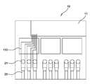
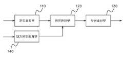
도 1 내지 도 5에 도시된 바와 같이, 본 발명의 제1 실시예에 따른 지상개폐기함의 온도 모니터링 장치는, 온도감지부(110), 변온판단부(120) 및 무선송신부(130)를 포함한다.1 to 5, the apparatus for monitoring the temperature of the ground closet box according to the first embodiment of the present invention includes a
온도감지부(110)는 지상개폐기함(10) 내에서 복수의 전력 케이블(20) 각각의 외주면에 귄취되는 복수의 온도센서(111)를 포함하여, 전력 케이블(20)의 귄취 지점별 온도를 감지한다.The
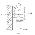
구체적으로, 도 3을 참조하면, 지상개폐기함(10)에는 T자 형상으로 형성되며, 지중으로부터 인출되는 전력 케이블(20)을 하단에 체결하고, 상부 일단을 지상개폐기(30)에 체결하는 케이블 연결구(21)가 더 마련된다. 여기서, 온도센서(111)는 복수의 전력 케이블(20) 마다, 전력 케이블(20)과 케이블 연결구(21)와 체결되는 제1 지점과, 케이블 연결구(21)와 지상개폐기(30)가 체결되는 제2 지점에 각각 권취된다. 즉, 도 3에서 제1 지점에 온도감지부(100B)가 권취되어 마련되고, 제2 지점에 온도감지부(110A)가 권취되어, 부하열이 가장 많이 발생되는 전력 공급의 출력단과 입력단에 각각 체결된다. 하나의 전력 케이블(20)에는 한 쌍의 온도감지부(110A, 110B)가 체결된다.3, the
변온판단부(120)는 지상개폐기함(10) 내에서 전장품 케이스 내측에 수용되며, 복수의 온도센서(111)에서 수신되는 온도값들을 비교하여 온도변화를 판단하고 변온 정보를 생성한다.The
구체적으로, 변온판단부(120)는, 복수의 온도센서(111)에서 감지되는 온도값 중 최저 온도값과, 복수의 온도센서(111)에서 감지되는 온도값 중 최고 온도값이 동일시각에 10℃ 이상 차이나는 경우, 부하열에 의해 온도변화가 발생하였음을 판단하는 것이 가능하다. 즉, 원칙적으로 서로 비슷한 부하열이 발생하여야 하지만, 최저 온도값 대비 10℃ 이상으로 최고 온도값이 발생하는 지점에 특히 이상 부하열에 의한 열화가 이루어질 수 있음을 모니터링하여 미리 알릴 수 있다.Specifically, the temperature-
또한, 도 5를 참조하면, 본 발명의 제1 실시예에 따른 지상개폐기함의 온도 모니터링 장치는, 전장품 케이스(11) 내에 수용되며, 지상개폐기함(10)의 대기 온도를 감지하는 대기온도감지부(140)를 더 포함하는 것이 가능하다. 이에 따라, 변온판단부(120)는, 대기 온도값을 기준으로 하여, 복수의 온도센서(111)에서 감지되는 온도값의 평균값과, 대기 온도값의 차이가 미리 설정한 제1 기준 문턱값 이상인 경우, 전체적으로 온도변화가 발생하였음을 판단하여 제2 변온 정보를 생성할 수 있다.5, the apparatus for monitoring the temperature of the ground closet box according to the first embodiment of the present invention includes an ambient temperature sensor (not shown) (140). ≪ / RTI > The
즉, 지상개폐기(30)의 고장 등으로 전체적으로 부하열이 급격히 증가는 경우에는 상기의 최저 온도 및 최고 온도 10℃ 차이를 이용하여 모니터링하기 부족한 면이 있다. 이에 따라 대기 중의 온도를 감지하여 이를 비교함으로써, 전체 열화를 미연에 방지할 수 있다. 여기서 제1 기준 문탁값은 계절적 요인을 감안하여 10℃ 내지 50℃로 조절할 수 있음은 물론이다.That is, in the case where the load heat increases sharply as a whole due to the failure of the
또한, 변온판단부(120)는, 복수의 온도센서(111)에서 감지되는 온도값 중 어느 하나의 온도값이 평균값 보다 낮게 나타나되, 평균값과의 차이가 미리 설정한 제2 기준 문턱값 이상인 경우, 해당 온도센서(111)가 오작동 중임을 판단하여 오작동검출 정보를 생성하고, 해당 온도센서(111)는 이후 온도 변화 판단시 제외시키는 것이 가능하다.The
즉, 온도센서(111)가 고장난 경우에는 상술한 온도 변화 판단에 영향을 끼칠 수 있으므로, 이를 방지하기 위하여 오작동 중인 온도센서(111)를 미리 검출하여 제외하도록 한다. 이때의 제2 기준 문턱값은 완전히 작동하지 않는 0℃ 로부터 대기온도와의 차이인 30℃로 설정할 수 있다.That is, if the
또한, 변온판단부(120)는, 복수의 온도센서(111)에서 감지되는 온도값 중 어느 하나의 온도값이 평균값 보다 높게 나타나되, 평균값과의 차이가 미리 설정한 제3 기준 문턱값 이상인 경우, 해당 온도센서(111)가 위치하는 지점에서 열화(烈火)가 발생됨을 판단하여 제3 변온 정보 및 열화지점 정보를 생성할 수 있다. 즉, 최저 온도값 대비 10℃ 이상으로 최고 온도값이 발생하는 지점을 찾아 내는 방법과 함깨, 또 다른 방법으로 이중으로 체크할 수 있으므로, 모니터링의 정확성 및 신뢰성이 보다 향상될 수 있다.The
무선송신부(130)는 지상개폐기함(10) 내에서 전장품 케이스 내측에 수용되며, 변온판단부(120)에서 변온 정보를 수신하여, 변온 정보를 관제센터로 무선 송신한다. 여기서, 무선송신부(130)는 와이파이 통신, 이동전화 데이터 통신을 통하여 무선 송신을 하는 것이 가능하다.The
<제2 실시예>≪ Embodiment 2 >
도 6 내지 도 8은 본 발명의 제2 실시예에 따른 지상개폐기함의 온도 모니터링 장치를 설명하기 위한 도면이다. 구체적으로, 도 6은 본 발명의 제2 실시예에 따른 지상개폐기함의 온도 모니터링 장치의 온도감지부의 구성요소를 나타낸 도면이고, 도 7은 본 발명의 제2 실시예에 따른 지상개폐기함의 온도 모니터링 장치의 귄취 테이프의 구성요소를 나타낸 단면도이며, 도 8은 본 발명의 제2 실시예에 따른 지상개폐기함의 온도 모니터링 장치의 귄취 테이프의 다른 구성요소를 나타낸 단면도이다.6 to 8 are views for explaining a temperature monitoring apparatus for a ground switch according to a second embodiment of the present invention. 6 is a block diagram showing the components of the temperature sensing unit of the temperature monitoring device of the ground switchgear according to the second embodiment of the present invention. FIG. 7 is a block diagram of the temperature monitoring device of the ground switchgear according to the second embodiment of the present invention. FIG. 8 is a cross-sectional view showing another constituent element of the winding tape of the apparatus for monitoring the temperature of the ground switchgear according to the second embodiment of the present invention. FIG.
도 6 내지 도 8에 도시된 바와 같이, 본 발명의 제2 실시예에 따른 온도감지부(110)는 온도센서(111), 리드선(112) 및 귄취 테이프(113)를 포함한다.6 to 8, the
온도센서(111)는 좁쌀과 같이 소형으로 형성되며, 온도를 감지하기 위하여 마련된다.The
리드선(112)은 일단이 온도센서(111)로부터 인출되며, 타단이 변온판단부(120)에 연결된다.One end of the
귄취 테이프(113)는 일면에 점성을 가지는 테이퍼 형상으로 형성되어, 복수의 온도 센서를 일면에 일정 간격으로 부착하고 리더선을 일면의 길이 방향을 따라 부착하며, 온도센서(111) 및 리드선(112)을 보호하고 전력 케이블(20)에 권취시키기 위하여 마련된다.The winding
이와 같은 구성에 의해 귄취 테이프(113)의 일면을 전력 케이블(20)의 외주면에 향하도록 하여 접착시켜 감는 것으로, 전력 케이블(20)의 일 지점의 외주면을 따라 온도센서(111)를 일정 간격으로 고정하는 것이 가능하다.The
이에 따라, 온도감지부(110)의 온도센서(111)를 전력 케이블(20)에 손쉽게 권취하여 고정할 수 있다.Accordingly, the
또한, 귄취 테이프(113)는, 단열재질의 섬유로 직조되어 가요성을 가지는 권취 천(113a)과, 귄취 천의 일면에 도포되는 접착층(113b)을 포함하는 것이 가능하다. 즉, 고온에 의한 권취 테이프(113)의 연소를 방지할 수 있으며, 온도센서(111)를 안전하게 보호할 수 있다.The winding
나아가, 본 발명의 제2 실시 따른 귄취 테이프(113)는, 석회질을 포함하는 단열재와 건조시 가요성을 가지는 수성 바인더를 혼합하여 형성되며, 권취 천의 타면과 측면을 따라 도포되어 적층되는 단열층(113c)을 더 포함할 수 있다.Further, the winding
이에 따라, 고온에 의한 권취 테이프(113)의 연소를 더욱더 방지할 수 있으며, 온도센서(111)를 더욱더 안전하게 보호할 수 있음은 물론이며, 외부의 대기와 차단으로, 외부요인의 간섭없이 온도센서(111)가 전력 케이블(20)에서 발생되는 부하열만을 정확하게 센싱할 수 있다.As a result, it is possible to further prevent the
한편, 온도센서(111)는 전력 케이블(20)의 하나의 지점에서 전후좌우 방향으로 4개로 형성되어 하나의 온도센서(111)군을 이루며, 변온판단부(120)는, 온도센서군의 각 온도센서(111)에서 감지되는 온도값의 평균값과, 온도센서군에서 감지되는 온도값 중 어느 하나의 온도값의 차이가 미리 설정한 제4 기준 문턱값 이상인 경우, 해당 온도센서(111)가 오작동 중임을 판단하여 제2 오작동검출 정보를 생성하고, 해당 온도센서(111)는 이후 온도 변화 판단시 제외시키는 것이 가능하다.The
즉, 하나의 지점에서 어느 하나의 온도센서(111)가 고장난 경우에는 상술한 온도 변화 판단에 영향을 끼칠 수 있으므로, 이를 방지하기 위하여 오작동 중인 온도센서(111)를 미리 검출하여 제외하도록 한다. 이때의 제4 기준 문턱값은 완전히 작동하지 않는 0℃ 로부터 대기온도와의 차이인 30℃로 설정할 수 있다. 또한, 하나의 지점에서 어느 하나의 온도센서(111)가 고장난 경우라도, 나머지 온도센서(111)를 이용하여 해당 지점의 부하열에 의한 온도변화를 센싱할 수 있다.That is, when any one of the
<제3 실시예>≪ Third Embodiment >
도 9는 본 발명의 제3 실시예에 따른 지상개폐기함의 온도 모니터링 장치를 설명하기 위한 블럭도이다.9 is a block diagram for explaining an apparatus for monitoring the temperature of a ground switch according to a third embodiment of the present invention.
도 9에 도시된 바와 같이, 본 발명의 제3 실시예에 따른 무선송신부(330)는 동작확인 신호를 관제센터로 주기적으로 송신하고 관제센터로부터 확인응답 신호를 회신하도록 설정한다.As shown in FIG. 9, the
이와 함께, 지상개폐기함의 온도 모니터링 장치는, 무선송신부(330)에 연결되어 동작확인 신호 및 확인응답 신호가 발생되지 않는 시간이, 미리 설정된 기준시간 문턱값 이상 지속되는 경우, 무선송신부(330)를 온오프시켜 리셋하는 송신리셋부(340)를 더 포함하는 것이 가능하다.In addition, the temperature monitoring apparatus of the terrestrial break switch box is connected to the
이에 따라, 본 발명의 제3 실시예에 따른 지상개폐기함의 온도 모니터링 장치는, 무선통신에 오작동 여부를 실시간 감시하여 리셋 동작으로 무선통신을 원활하게 이루어지게 할 수 있다.Accordingly, the apparatus for monitoring the temperature of the ground switchgear according to the third embodiment of the present invention can smoothly perform the wireless communication by performing the reset operation by monitoring the malfunction in real time.
또한, 본 발명의 제3 실시예에 따른 전장품 케이스(11)는 단열 재질로 형성됨으로써, 화재, 외부충격 등에 대하여 변온판단부(320), 무선송신부(330) 및 송신리셋부(340) 등 각각의 구성요소들을 안전하게 보호할 수 있는 장점이 있다.The
이와 같이, 상술한 본 발명의 기술적 구성은 본 발명이 속하는 기술분야의 당업자가 본 발명의 그 기술적 사상이나 필수적 특징을 변경하지 않고서 다른 구체적인 형태로 실시될 수 있다는 것을 이해할 수 있을 것이다.As described above, it is to be understood that the technical structure of the present invention can be embodied in other specific forms without departing from the spirit and essential characteristics of the present invention.
그러므로 이상에서 기술한 실시예들은 모든 면에서 예시적인 것이며 한정적인 것이 아닌 것으로서 이해되어야 하고, 본 발명의 범위는 상기 상세한 설명보다는 후술하는 특허청구범위에 의하여 나타나며, 특허청구범위의미 및 범위 그리고 그 등가 개념으로부터 도출되는 모든 변경 또는 변형된 형태가 본 발명의 범위에 포함되는 것으로 해석되어야 한다.Therefore, it should be understood that the above-described embodiments are to be considered in all respects as illustrative and not restrictive, the scope of the invention being indicated by the appended claims rather than the foregoing description, All changes or modifications that come within the scope of the present invention should be construed as being included within the scope of the present invention.
10 : 지상개폐기함
11 : 전장품 케이스
20 : 전력 케이블
21 : 케이블 연결구
30 : 지상개폐기
110, 110A, 110B, 310 : 온도감지부
111 : 온도센서
112 : 리드선
113 : 귄취 테이프
113a : 권취 천
113b : 접착층
113c : 단열층
120, 320 : 변온판단부
130, 330 : 무선송신부
140 : 대기온도감지부
340 : 송신리셋부10: Ground switchgear box
11: Electrical equipment case
20: Power cable
21: Cable connector
30: ground switchgear
110, 110A, 110B, and 310:
111: Temperature sensor
112: Lead wire
113: Winding tape
113a:
113b:
113c: insulation layer
120, 320:
130, 330: radio transmission unit
140: Ambient temperature sensing unit
340: Transmission reset section
Claims (12)
Translated fromKorean지상개폐기함 내에서 전장품 케이스 내측에 수용되며, 복수의 상기 온도센서에서 수신되는 온도값들을 비교하여 온도변화를 판단하고 변온 정보를 생성하는 변온판단부; 및
지상개폐기함 내에서 전장품 케이스 내측에 수용되며, 상기 변온판단부에서 변온 정보를 수신하여, 상기 변온 정보를 관제센터로 무선 송신하는 무선송신부;
를 포함하는 지상개폐기함의 온도 모니터링 장치.A temperature sensing unit including a plurality of temperature sensors wound around an outer circumferential surface of each of the plurality of power cables in the ground switchgear to sense the temperature of the power cable at each winding point;
A temperature determination unit which is accommodated inside the electrical component case in the ground switch cabin and compares the temperature values received from the plurality of temperature sensors to determine the temperature change and generate the temperature change information; And
A wireless transmission unit accommodated inside the electrical component case in the ground switch case and receiving the temperature change information from the temperature change determination unit and wirelessly transmitting the temperature change information to the control center;
And a temperature monitoring device for monitoring the temperature of the ground switch housing.
상기 변온판단부는, 복수의 상기 온도센서에서 감지되는 온도값 중 최저 온도값과, 복수의 상기 온도센서에서 감지되는 온도값 중 최고 온도값이 동일시각에 10℃ 이상 차이나는 경우, 온도변화가 발생하였음을 판단하는 것을 특징으로 하는 지상개폐기함의 온도 모니터링 장치.The method according to claim 1,
The temperature determination unit may determine that a temperature change occurs when the lowest temperature value among the temperature values sensed by the plurality of temperature sensors and the highest temperature value among the temperature values sensed by the plurality of temperature sensors are different by 10 ° C or more at the same time Wherein the temperature monitoring device detects the temperature of the ground door.
상기 전장품 케이스 내에 수용되며, 지상개폐기함의 대기 온도를 감지하는 대기온도감지부를 더 포함하며,
상기 변온판단부는, 상기 대기 온도값을 기준으로 하여, 복수의 상기 온도센서에서 감지되는 온도값의 평균값과, 상기 대기 온도값의 차이가 미리 설정한 제1 기준 문턱값 이상인 경우, 전체적으로 온도변화가 발생하였음을 판단하여 제2 변온 정보를 생성하는 것을 특징으로 하는 지상개폐기함의 온도 모니터링 장치.3. The method of claim 2,
And an atmospheric temperature sensing unit that is accommodated in the electrical component case and senses an atmospheric temperature of the ground-
Wherein the temperature change determining unit is configured to determine whether or not the temperature change as a whole is greater than the first reference threshold value when the difference between the average value of the temperature values sensed by the plurality of temperature sensors and the atmospheric temperature value, And the second temperature change information is generated based on the second temperature change information.
상기 변온판단부는, 복수의 상기 온도센서에서 감지되는 온도값 중 어느 하나의 온도값이 상기 평균값 보다 낮게 나타나되, 상기 평균값과의 차이가 미리 설정한 제2 기준 문턱값 이상인 경우, 해당 온도센서가 오작동 중임을 판단하여 오작동검출 정보를 생성하고, 해당 온도센서는 이후 온도 변화 판단시 제외시키는 것을 특징으로 하는 지상개폐기함의 온도 모니터링 장치.The method of claim 3,
Wherein the temperature determination unit determines that any one of the temperature values sensed by the plurality of temperature sensors is lower than the average value and if the difference from the average value is equal to or greater than a predetermined second reference threshold value, And the malfunction detection information is generated, and the temperature sensor is excluded at the time of determining the temperature change thereafter.
상기 변온판단부는, 복수의 상기 온도센서에서 감지되는 온도값 중 어느 하나의 온도값이 상기 평균값 보다 높게 나타나되, 상기 평균값과의 차이가 미리 설정한 제3 기준 문턱값 이상인 경우, 해당 온도센서가 위치하는 지점에서 열화(烈火)가 발생됨을 판단하여 제3 변온 정보 및 열화지점 정보를 생성하는 것을 특징으로 하는 지상개폐기함의 온도 모니터링 장치.5. The method of claim 4,
Wherein the temperature determination unit determines that any one of the temperature values sensed by the plurality of temperature sensors is higher than the average value and if the difference from the average value is equal to or greater than a predetermined third reference threshold value, Wherein the third temperature change information and the deteriorated point information are generated by determining that detonation occurs at a point where the first and second temperature change points are located.
T자 형상으로 형성되며, 지중으로부터 인출되는 상기 전력 케이블을 하단에 체결하고, 상부 일단을 지상개폐기에 체결하는 케이블 연결구가 더 마련되며,
상기 온도센서는 복수의 상기 전력 케이블 마다, 상기 전력 케이블과 상기 케이블 연결구과 체결되는 제1 지점과, 상기 케이블 연결구와 상기 지상개폐기가 체결되는 제2 지점에 각각 권취되는 것을 특징으로 하는 지상개폐기함의 온도 모니터링 장치.6. The method of claim 5,
A cable connection port formed in a T shape and fastening the power cable drawn out from the ground to the lower end and fastening the upper end of the power cable to the ground switch,
Wherein the temperature sensor is wound on each of the plurality of power cables at a first point to be engaged with the power cable and the cable connecting port and at a second point to which the cable connecting port and the ground switch are fastened, Monitoring device.
상기 온도감지부는,
온도를 감지하기 위하여 마련되는 소형의 온도센서와,
일단이 상기 온도센서로부터 인출되며, 타단이 상기 변온판단부에 연결되는 리드선과,
일면에 점성을 가지는 테이퍼 형상으로 형성되어, 복수의 상기 온도 센서를 상기 일면에 일정 간격으로 부착하고 상기 리더선을 상기 일면의 길이 방향을 따라 부착하며, 상기 온도센서 및 상기 리드선을 보호하고 상기 전력 케이블에 권취시키기 위한 귄취 테이프를 포함하여,
상기 귄취 테이프의 일면을 상기 전력 케이블의 외주면에 향하도록 하여 접착시켜 감는 것으로, 상기 전력 케이블의 일 지점의 외주면을 따라 상기 온도센서를 일정 간격으로 고정하는 것을 특징으로 하는 지상개폐기함의 온도 모니터링 장치.The method according to claim 6,
Wherein the temperature sensing unit comprises:
A small temperature sensor provided for sensing the temperature,
A lead wire whose one end is drawn out from the temperature sensor and the other end is connected to the temperature-
And a plurality of temperature sensors are attached to the one surface at regular intervals and the leader wires are attached along the longitudinal direction of the one surface and the temperature sensor and the lead wires are protected, Including a winding tape for winding on a cable,
Wherein the temperature sensor is fixed at a predetermined interval along an outer circumferential surface of one point of the power cable by adhering one surface of the winding tape to the outer circumferential surface of the power cable.
상기 귄취 테이프는, 단열재질의 섬유로 직조되어 가요성을 가지는 권취 천과, 귄취 천의 일면에 도포되는 접착층을 포함하는 것을 특징으로 하는 지상개폐기함의 온도 모니터링 장치.8. The method of claim 7,
Wherein the winding tape comprises a winding cloth which is woven from fibers of heat insulating material and has flexibility and an adhesive layer which is applied to one surface of the winding cloth.
상기 귄취 테이프는, 석회질을 포함하는 단열재와 건조시 가요성을 가지는 수성 바인더를 혼합하여 형성되며, 상기 권취 천의 타면과 측면을 따라 도포되어 적층되는 단열층을 더 포함하는 것을 특징으로 하는 지상개폐기함의 온도 모니터링 장치.9. The method of claim 8,
Wherein the winding tape further comprises a heat insulating layer formed by mixing a heat insulating material including calcareous material and an aqueous binder having flexibility during drying and being coated and laminated along the other surface and the side surface of the winding cloth Temperature monitoring device.
상기 온도센서는 상기 전력 케이블의 하나의 지점에서 전후좌우 방향으로 4개로 형성되어 하나의 온도센서군을 이루며,
상기 변온판단부는, 상기 온도센서군의 각 온도센서에서 감지되는 온도값의 평균값과, 상기 온도센서군에서 감지되는 온도값 중 어느 하나의 온도값의 차이가 미리 설정한 제4 기준 문턱값 이상인 경우, 해당 온도센서가 오작동 중임을 판단하여 제2 오작동검출 정보를 생성하고, 해당 온도센서는 이후 온도 변화 판단시 제외시키는 것을 특징으로 하는 지상개폐기함의 온도 모니터링 장치.8. The method of claim 7,
The temperature sensor is formed as four temperature sensors in the front, back, left and right directions at one point of the power cable,
Wherein the temperature determining unit determines that the temperature difference is greater than or equal to a fourth reference threshold value that is set in advance by a difference between an average value of temperature values sensed by the temperature sensors of the temperature sensor group and a temperature value sensed by the temperature sensor group And generates second malfunction detection information by judging that the corresponding temperature sensor is malfunctioning, and the temperature sensor thereafter excludes it when judging a temperature change.
상기 전장품 케이스는 단열 재질로 형성되는 것을 특징으로 하는 지상개폐기함의 온도 모니터링 장치.The method according to claim 1,
Wherein the electrical component case is formed of a heat insulating material.
상기 무선송신부는 동작확인 신호를 관제센터로 주기적으로 송신하고 관제센터로부터 확인응답 신호를 회신하도록 설정하고,
상기 무선송신부에 연결되어 상기 동작확인 신호 및 상기 확인응답 신호가 발생되지 않는 시간이, 미리 설정된 기준시간 문턱값 이상 지속되는 경우, 상기 무선송신부를 온오프시켜 리셋하는 송신리셋부를 더 포함하는 것을 특징으로 하는 지상개폐기함의 온도 모니터링 장치.The method according to claim 1,
Wherein the radio transmission unit periodically transmits an operation confirmation signal to the control center and is configured to return an acknowledgment signal from the control center,
And a transmission reset unit connected to the radio transmission unit and configured to turn on and off the radio transmission unit when the time during which the operation confirmation signal and the acknowledgment signal are not generated continues over a predetermined reference time threshold value The temperature monitoring device of the ground-type switch box.
Priority Applications (1)
| Application Number | Priority Date | Filing Date | Title |
|---|---|---|---|
| KR1020150050106AKR20160120921A (en) | 2015-04-09 | 2015-04-09 | Apparatus for monitering temperature of pad switch box |
Applications Claiming Priority (1)
| Application Number | Priority Date | Filing Date | Title |
|---|---|---|---|
| KR1020150050106AKR20160120921A (en) | 2015-04-09 | 2015-04-09 | Apparatus for monitering temperature of pad switch box |
Publications (1)
| Publication Number | Publication Date |
|---|---|
| KR20160120921Atrue KR20160120921A (en) | 2016-10-19 |
Family
ID=57250663
Family Applications (1)
| Application Number | Title | Priority Date | Filing Date |
|---|---|---|---|
| KR1020150050106AAbandonedKR20160120921A (en) | 2015-04-09 | 2015-04-09 | Apparatus for monitering temperature of pad switch box |
Country Status (1)
| Country | Link |
|---|---|
| KR (1) | KR20160120921A (en) |
Cited By (4)
| Publication number | Priority date | Publication date | Assignee | Title |
|---|---|---|---|---|
| CN108255120A (en)* | 2017-12-01 | 2018-07-06 | 国网北京市电力公司 | The fault handling method and device of distribution box, the monitoring system of distribution box |
| WO2021120118A1 (en)* | 2019-12-19 | 2021-06-24 | Abb Schweiz Ag | Apparatus for measuring temperature of switchgear, assembling method thereof and switchgear |
| CN113031502A (en)* | 2021-03-07 | 2021-06-25 | 广东电网有限责任公司广州供电局 | Low-voltage contact cabinet self-adaptive control method, system and device based on temperature sensing |
| KR102659708B1 (en)* | 2023-09-07 | 2024-04-23 | 주식회사 아이테크 | System for monitoring deterioration of switchgear(high-voltage switchgear, low-voltage switchgear, motor control board, distributing board) |
Citations (1)
| Publication number | Priority date | Publication date | Assignee | Title |
|---|---|---|---|---|
| KR100978892B1 (en) | 2009-11-13 | 2010-08-30 | 한국전력산업과학기술 주식회사 | Apparatus for blocking dew condensing of pad switch and installation method thereof |
- 2015
- 2015-04-09KRKR1020150050106Apatent/KR20160120921A/ennot_activeAbandoned
Patent Citations (1)
| Publication number | Priority date | Publication date | Assignee | Title |
|---|---|---|---|---|
| KR100978892B1 (en) | 2009-11-13 | 2010-08-30 | 한국전력산업과학기술 주식회사 | Apparatus for blocking dew condensing of pad switch and installation method thereof |
Cited By (5)
| Publication number | Priority date | Publication date | Assignee | Title |
|---|---|---|---|---|
| CN108255120A (en)* | 2017-12-01 | 2018-07-06 | 国网北京市电力公司 | The fault handling method and device of distribution box, the monitoring system of distribution box |
| WO2021120118A1 (en)* | 2019-12-19 | 2021-06-24 | Abb Schweiz Ag | Apparatus for measuring temperature of switchgear, assembling method thereof and switchgear |
| CN113031502A (en)* | 2021-03-07 | 2021-06-25 | 广东电网有限责任公司广州供电局 | Low-voltage contact cabinet self-adaptive control method, system and device based on temperature sensing |
| KR102659708B1 (en)* | 2023-09-07 | 2024-04-23 | 주식회사 아이테크 | System for monitoring deterioration of switchgear(high-voltage switchgear, low-voltage switchgear, motor control board, distributing board) |
| KR102659709B1 (en)* | 2023-09-07 | 2024-04-23 | 주식회사 아이테크 | System for monitoring deterioration of switchgear(high-voltage switchgear, low-voltage switchgear, motor control board, distributing board) and detecting abnormal operation of internal sensors of the switchgear |
Similar Documents
| Publication | Publication Date | Title |
|---|---|---|
| KR101889834B1 (en) | Smart switchboard system | |
| US10608830B2 (en) | Power over fiber enabled sensor system | |
| WO2020055667A3 (en) | Electrical power cable monitoring device including partial discharge sensor | |
| KR101963853B1 (en) | Fault section detection device by connecting point of underground distribution line | |
| KR101915041B1 (en) | Branch line connection connector to power distribution line | |
| KR20160120921A (en) | Apparatus for monitering temperature of pad switch box | |
| US9725280B2 (en) | Connecting device for measurement tapes in elevator devices | |
| JP2015051876A (en) | Measuring tape for elevator device | |
| WO2018012741A1 (en) | System for observing resistance and current of ground line | |
| US11143392B2 (en) | Humidity alarm monitoring system for stage light | |
| CN207636656U (en) | A kind of cable sheath grounding circulation on-line monitoring equipment | |
| KR102321181B1 (en) | Apparatus and method for monitoring the occurrence of ground fault in solar power generation system | |
| KR101879742B1 (en) | Solar power generating system having arc detector function of pv modules and prevent deterioration | |
| KR102356233B1 (en) | busduct joint and multi point temperature monitering system of busduct including the same | |
| KR102124659B1 (en) | busduct joint | |
| KR102238913B1 (en) | recognizing method of temperature sensor for multi point temperature monitering system of busduct | |
| KR101285825B1 (en) | Power supply system of transmission tower using optical power transmission device and method thereof, data transmitting and receiving method using the optical power transmission device | |
| US8526156B2 (en) | High speed signaling of power system conditions | |
| US20150280642A1 (en) | Solar photovoltaic module monitoring and control system | |
| KR101869055B1 (en) | Underground distribution line connector | |
| KR102308824B1 (en) | Management system for distribution panel having function protecting dewfall | |
| KR20230056989A (en) | Apparatus for Detecting Faulty Terminal Connection in Distribution Panel and Method Therefore | |
| EP4163651A1 (en) | Device for detecting electrical arc events in an electrical system | |
| US11381074B2 (en) | Electrical protection system and method for a high-voltage direct current system | |
| CN211014584U (en) | Load on-site detection device and ion pump power supply system |
Legal Events
| Date | Code | Title | Description |
|---|---|---|---|
| A201 | Request for examination | ||
| PA0109 | Patent application | Patent event code:PA01091R01D Comment text:Patent Application Patent event date:20150409 | |
| PA0201 | Request for examination | ||
| E902 | Notification of reason for refusal | ||
| PE0902 | Notice of grounds for rejection | Comment text:Notification of reason for refusal Patent event date:20160927 Patent event code:PE09021S01D | |
| PG1501 | Laying open of application | ||
| E701 | Decision to grant or registration of patent right | ||
| PE0701 | Decision of registration | Patent event code:PE07011S01D Comment text:Decision to Grant Registration Patent event date:20161205 | |
| PC1904 | Unpaid initial registration fee |