KR20160118519A - Fitness Equipment - Google Patents
Fitness EquipmentDownload PDFInfo
- Publication number
- KR20160118519A KR20160118519AKR1020150046756AKR20150046756AKR20160118519AKR 20160118519 AKR20160118519 AKR 20160118519AKR 1020150046756 AKR1020150046756 AKR 1020150046756AKR 20150046756 AKR20150046756 AKR 20150046756AKR 20160118519 AKR20160118519 AKR 20160118519A
- Authority
- KR
- South Korea
- Prior art keywords
- handle
- housing
- hole
- adjusting
- resistance
- Prior art date
- Legal status (The legal status is an assumption and is not a legal conclusion. Google has not performed a legal analysis and makes no representation as to the accuracy of the status listed.)
- Abandoned
Links
- 238000000034methodMethods0.000claimsdescription21
- 230000001105regulatory effectEffects0.000claimsdescription7
- 230000001965increasing effectEffects0.000claimsdescription5
- 230000002265preventionEffects0.000claimsdescription2
- 230000002093peripheral effectEffects0.000claims1
- 210000001835visceraAnatomy0.000description5
- 241000251539Vertebrata <Metazoa>Species0.000description3
- 210000001015abdomenAnatomy0.000description3
- 210000003205muscleAnatomy0.000description3
- 230000001276controlling effectEffects0.000description2
- 230000000694effectsEffects0.000description2
- 230000002708enhancing effectEffects0.000description2
- 239000000463materialSubstances0.000description2
- 238000006467substitution reactionMethods0.000description2
- 208000008035Back PainDiseases0.000description1
- JOYRKODLDBILNP-UHFFFAOYSA-NEthyl urethaneChemical compoundCCOC(N)=OJOYRKODLDBILNP-UHFFFAOYSA-N0.000description1
- 241001465754MetazoaSpecies0.000description1
- 230000002567autonomic effectEffects0.000description1
- 235000019577caloric intakeNutrition0.000description1
- 238000010586diagramMethods0.000description1
- 239000013013elastic materialSubstances0.000description1
- 238000005516engineering processMethods0.000description1
- 210000000918epididymisAnatomy0.000description1
- 201000010063epididymitisDiseases0.000description1
- 230000005021gaitEffects0.000description1
- 238000012986modificationMethods0.000description1
- 230000004048modificationEffects0.000description1
- 230000003387muscularEffects0.000description1
- 230000000149penetrating effectEffects0.000description1
- 238000005728strengtheningMethods0.000description1
Images


Classifications
- A—HUMAN NECESSITIES
- A63—SPORTS; GAMES; AMUSEMENTS
- A63B—APPARATUS FOR PHYSICAL TRAINING, GYMNASTICS, SWIMMING, CLIMBING, OR FENCING; BALL GAMES; TRAINING EQUIPMENT
- A63B23/00—Exercising apparatus specially adapted for particular parts of the body
- A63B23/02—Exercising apparatus specially adapted for particular parts of the body for the abdomen, the spinal column or the torso muscles related to shoulders (e.g. chest muscles)
- A63B23/0233—Muscles of the back, e.g. by an extension of the body against a resistance, reverse crunch
- A63B23/0238—Spinal column
- A—HUMAN NECESSITIES
- A63—SPORTS; GAMES; AMUSEMENTS
- A63B—APPARATUS FOR PHYSICAL TRAINING, GYMNASTICS, SWIMMING, CLIMBING, OR FENCING; BALL GAMES; TRAINING EQUIPMENT
- A63B22/00—Exercising apparatus specially adapted for conditioning the cardio-vascular system, for training agility or co-ordination of movements
- A63B22/02—Exercising apparatus specially adapted for conditioning the cardio-vascular system, for training agility or co-ordination of movements with movable endless bands, e.g. treadmills
- A—HUMAN NECESSITIES
- A63—SPORTS; GAMES; AMUSEMENTS
- A63B—APPARATUS FOR PHYSICAL TRAINING, GYMNASTICS, SWIMMING, CLIMBING, OR FENCING; BALL GAMES; TRAINING EQUIPMENT
- A63B22/00—Exercising apparatus specially adapted for conditioning the cardio-vascular system, for training agility or co-ordination of movements
- A63B22/20—Exercising apparatus specially adapted for conditioning the cardio-vascular system, for training agility or co-ordination of movements using rollers, wheels, castors or the like, e.g. gliding means, to be moved over the floor or other surface, e.g. guide tracks, during exercising
- A63B22/201—Exercising apparatus specially adapted for conditioning the cardio-vascular system, for training agility or co-ordination of movements using rollers, wheels, castors or the like, e.g. gliding means, to be moved over the floor or other surface, e.g. guide tracks, during exercising for moving a support element in reciprocating translation, i.e. for sliding back and forth on a guide track
- A—HUMAN NECESSITIES
- A63—SPORTS; GAMES; AMUSEMENTS
- A63B—APPARATUS FOR PHYSICAL TRAINING, GYMNASTICS, SWIMMING, CLIMBING, OR FENCING; BALL GAMES; TRAINING EQUIPMENT
- A63B23/00—Exercising apparatus specially adapted for particular parts of the body
- A63B23/035—Exercising apparatus specially adapted for particular parts of the body for limbs, i.e. upper or lower limbs, e.g. simultaneously
Landscapes
- Health & Medical Sciences (AREA)
- General Health & Medical Sciences (AREA)
- Physical Education & Sports Medicine (AREA)
- Orthopedic Medicine & Surgery (AREA)
- Engineering & Computer Science (AREA)
- Biomedical Technology (AREA)
- Neurology (AREA)
- Cardiology (AREA)
- Vascular Medicine (AREA)
- Pulmonology (AREA)
- Rehabilitation Tools (AREA)
Abstract
Translated fromKoreanDescription
Translated fromKorean본 발명은 운동기구에 관한 것이다. 더욱 상세하게는, 본 발명은 양손과 양발을 이용하여 척추에 파동운동이 일어나도록 하여 척추의 본연의 기능을 회복하는 운동기구에 관한 것이다.The present invention relates to exercise machines. More particularly, the present invention relates to a fitness device that restores the original function of the vertebra by causing a wave motion to occur in the spine using both hands and feet.
최근에는 의료기술의 발달로 100세 시대에 들어서게 되었으며, 그로 인해 건강에 대한 관심이 증대되고 있다. 그러나, 고정된 자세와 운동부족으로 인한 근육의 약화 및 인류의 직립보행으로 인하여 하중을 받치는 관절에 무리로 인하여 허리 디스크나 요통 등의 많은 문제가 발생하고 있다..In recent years, the advancement of medical technology has led to the age of 100, and health care interest is increasing. However, due to the weakness of the muscles due to the fixed posture and lack of exercise, and the erect gait of the human being, many problems such as the back disk and back pain have been caused due to the load on the joints.
일반적인 척추 동물은 전방진행의 주 추진력을 얻기 위해 척추를 이용하나, 직립 보행을 하는 인간은 다른 척추 동물과는 달리 척추의 추진력을 이용한 운동을 지상에서 해줄 수 없었다.In general, vertebrate animals use the spine to gain the main driving force of forward movement, but unlike other vertebrates, those who are upright can not exercise spinal propulsion.
네발 척추동물들은 척추의 수평 파동운동을 이용하여 걷고, 수직파동운동을 통해 달리나, 인간은 걷기나 달리기에서 척추가 아닌 다리로 전방진행을 한다.The vertebrate vertebrates use a horizontal wave motion of the vertebrae to walk, a vertical wave motion, and a human to walk forward or forward to the leg rather than the vertebrae.
걷기나 달리기를 실내에서 하기 위한 런닝머신은 실제로 제자리 뛰기 운동을 하게 되며, 런닝머신 내부의 모터가 발판을 돌려 운동을 하는 구조이므로 척추를 이용한 전방추진력을 전혀 사용할 수 없는 문제점이 있었다.The treadmill for walking or running indoors is actually in the same place. The motor inside the treadmill is used to rotate the footplate, so there is a problem that the front propulsion using the spine can not be used at all.
대한민국 등록특허 제10-0687911호.Korean Patent No. 10-0687911.
본 발명의 실시예는 척추를 지면에 수평에 가깝게 유지시키며 걷기와 달리기를 할 수 있는 기구로 척추의 자연적 기능을 회복할 수 있는 운동기구를 제공하고자 한다.An embodiment of the present invention is to provide a fitness device capable of restoring the natural function of the vertebrae by keeping the vertebrae close to the ground horizontally and performing walking and running.
또한, 척추를 지면과 수평에 가깝도록 유지한 상태로 운동하도록 구비되어 내장기관이 부드러운 복부에서 함께 운동할 수 있는 운동기구를 제공하고자 한다.Also, it is intended to provide a exercise device which is provided to move in a state in which the vertebrae are kept close to a horizontal level with the ground, so that the internal organ can exercise together in the soft abdomen.
본 발명의 바람직한 일실시예인 운동기구는, 적어도 하나의 구동롤러를 구비하는 지지프레임; 상기 구동롤러에 감겨서 사용자의 동작에 의해서 회전하는 구동벨트; 상기 구동벨트에 인접하도록 위치하는 지지부; 상기 지지부와 연결되며, 상기 사용자의 동작에 의해서 수평방향으로 시계추 운동을 하는 손잡이를 구비하는 손잡이회동부;를 포함할 수 있다.According to a preferred embodiment of the present invention, a movement mechanism includes: a support frame having at least one drive roller; A drive belt wound around the drive roller and rotated by a user's operation; A support positioned adjacent the drive belt; And a knob pivoting part connected to the support part and having a knob for horizontally moving the knob by the operation of the user.
바람직하게는, 상기 손잡이와 연결되어 상기 손잡이의 하중을 조절할 수 있는 하중조절부를 포함할 수 있다.Preferably, the load control unit may include a load controller connected to the handle to adjust a load of the handle.
바람직하게는, 상기 하중조절부는 탄성체 또는 유압실린더를 이용하는 것을 특징으로 할 수 있다.Preferably, the load regulator uses an elastic body or a hydraulic cylinder.
바람직하게는, 상기 지지부는 상기 손잡이회동부의 높이를 조절할 수 있는 높이조절부를 더 포함할 수 있다.Preferably, the support portion may further include a height adjusting portion capable of adjusting a height of the handle turning portion.
바람직하게는, 상기 손잡이 회동부는, 내부에 수직방향의 회전축이 구비되며, 상기 손잡이가 관통하기 위한 하우징관통홀이 형성되는 하우징, 중앙에 상기 회전축과 결합하도록 회전축관통홀이 형성되는 손잡이를 포함할 수 있다.Preferably, the handle pivoting portion includes a housing having a vertical rotation shaft therein, a housing through hole for the handle to be inserted therein, and a handle having a rotation shaft through hole formed at the center thereof to engage with the rotation shaft .
바람직하게는, 상기 하우징은 상부하우징과 하부하우징의 결합에 의해서 형성되는 것을 특징으로 할 수 있다.Preferably, the housing is formed by a combination of an upper housing and a lower housing.
바람직하게는, 상기 손잡이회동부는, 상기 회전축과 연결되도록 베어링관통공이 형성되는 베어링을 더 포함하며, 상기 베어링은 상기 손잡이와 상기 하우징의 하부면 사이에 위치하는 것을 특징으로 할 수 있다.Preferably, the handle pivot portion further includes a bearing having a bearing through hole connected to the rotation shaft, and the bearing is located between the handle and the lower surface of the housing.
바람직하게는, 상기 베어링은 볼베어링인 것을 특징으로 할 수 있다.Preferably, the bearing is a ball bearing.
바람직하게는, 상기 하우징의 내부에는 상기 손잡이가 시계추 운동시 상기 하우징관통공을 형성하는 외벽과 닿는 것을 방지하기 위한 적어도 하나의 충격방지부재가 구비될 수 있다.Preferably, the housing includes at least one shock-absorbing member for preventing the handle from touching the outer wall forming the housing through-hole when the watch is in a clockwise motion.
바람직하게는, 상기 충격방지부재는 에어쿠션인 것을 특징으로 할 수 있다.Preferably, the impact-preventing member is an air cushion.
바람직하게는, 상기 하우징관통홀은 구형으로 형성되며, 상기 손잡이의 중심부는 구형상의 볼조인트로 구비되고, 상기 볼조인트의 중심에 형성되는 상기 회전축관통홀은 중심부에서 외각부로 갈수록 직경이 증가하는 원형의 단면형상을 가지는 것을 특징으로 할 수 있다.Preferably, the housing through-hole is formed in a spherical shape, and a central portion of the handle is formed of a spherical ball joint, and the rotational shaft through-hole formed at the center of the ball joint is circular Sectional shape.
바람직하게는, 상기 회전축관통홀의 중심부와 상기 회전축 사이에는 마모방지부가 구비될 수 있다.Preferably, a wear prevention part may be provided between the center of the rotation shaft through hole and the rotation shaft.
바람직하게는, 상기 구동벨트에는 운동중심선이 형성되는 것을 특징으로 할 수 있다.Preferably, a center line of motion is formed on the drive belt.
바람직하게는, 상기 사용자의 운동상태 및 운동량을 측정하는 제어부 및 상기 제어부에서 측정된 운동상태 및 운동량을 나타내는 디스플레이부를 더 포함할 수 있다.The controller may further include a controller for measuring a motion state and an amount of motion of the user, and a display unit for indicating a motion state and an amount of exercise measured by the controller.
바람직하게는, 상기 제어부의 조절에 의하여 상기 구동벨트의 저항력을 조절하는 저항조절부를 더 포함할 수 있다.The controller may further include a resistance adjusting unit for adjusting the resistance of the driving belt by adjusting the control unit.
바람직하게는, 상기 구동벨트에는 자석이 구비되며, 상기 저항조절부는 내부에 구비된 자석과 상기 구동벨트의 간격을 조절하여 저항을 조절하는 것을 특징으로 할 수 있다.Preferably, the driving belt is provided with a magnet, and the resistance adjusting unit adjusts the resistance by adjusting a gap between the magnet and the driving belt.
바람직하게는, 상기 저항조절부에는 적어도 하나의 마찰부재가 구비되어 상기 구동벨트의 저항을 조절하는 것을 특징으로 할 수 있다.Preferably, the resistance adjusting unit is provided with at least one friction member to adjust the resistance of the driving belt.
본 발명의 일실시예에 따른 운동기구에 의하면, 척추를 지면과 수평에 가깝게 유지시킨 상태로 걷기와 달리기를 하여 척추의 자연적 기능을 회복하여 몸의 관절과 근육체계가 자연적 기능을 할 수 있는 효과가 있다.According to the exercise device according to the embodiment of the present invention, the spine can be restored to its natural function by walking and running while keeping the vertebrae close to the ground, so that the joints and muscular system of the body can function naturally .
또한, 다리만이 아닌 척추를 이용하여 전방추진력을 얻음으로 기립근 강화 및 척추 유연성을 증대할 수 있는 효과가 있다.In addition, using the spine instead of the legs to obtain anterior thrust, strengthening of the epididymis and vertebrae flexibility is effective.
또한, 내장기관이 부드러운 복부에 놓인 상태로 척추의 움직임에 따라 함께 출렁이도록 운동하게 되어 내장기관이 건강해 지는 효과가 있다.Also, the internal organs are placed on the soft abdomen and move along with the movement of the vertebrae, so that the internal organs are healthy.
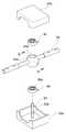
도 1은 본 발명의 바람직한 실시예인 운동기구의 사시도이고,
도 2는 도 1의 구성요소인 손잡이회동부 제1 실시예의 사시도이고,
도 3은 도 2의 분해사시도이고,
도 4는 도 1의 구성요소인 손잡이회동부 제2 실시예의 사시도이고,
도 5는 도 4의 분해사시도이고,
도 6은 도 5의 볼조인트에 형성되는 볼조인트 관통홀의 형상을 나타내는 단면도이고,
도 7은 도 1의 운동기구의 구동벨트의 저항력을 조절하기 위한 제1 실시예를 나타내는 도면이고,
도 8은 도 1의 운동기구의 구동벨트의 저항력을 조절하기 위한 제2 실시예를 나타내는 도면이고,
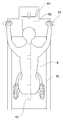
도 9은 본 발명의 바람직한 실시예인 운동기구를 사용자가 탑승하였을 때, 자세를 나타내는 도면이고,
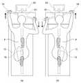
도 10의 (a) 및 (b)는 사용자의 동작에 따른 손잡이 회동부의 구동 상태를 나타내기 위한 도면이다.FIG. 1 is a perspective view of a fitness device, which is a preferred embodiment of the present invention,
Fig. 2 is a perspective view of the first embodiment of the handle pivot portion, which is a component of Fig. 1,
Fig. 3 is an exploded perspective view of Fig. 2,
Fig. 4 is a perspective view of the second embodiment of the handle pivot portion, which is a component of Fig. 1,
FIG. 5 is an exploded perspective view of FIG. 4,
6 is a sectional view showing the shape of a ball joint through hole formed in the ball joint of FIG. 5,
FIG. 7 is a view showing a first embodiment for adjusting the resistance of the drive belt of the exercise device of FIG. 1,
FIG. 8 is a view showing a second embodiment for adjusting the resistance of the driving belt of the exercise device of FIG. 1,
9 is a view showing a posture when a user wears a exercise machine, which is a preferred embodiment of the present invention,
10 (a) and 10 (b) are diagrams showing the driving state of the handle pivoting portion according to the operation of the user.
이하, 본 발명의 바람직한 실시예를 첨부된 도면들을 참조하여 본 발명의 실시예에 따른 운동기구를 상세히 설명한다. 우선 각 도면의 구성 요소들에 참조 부호를 부가함에 있어서, 동일한 구성 요소들에 대해서는 비록 다른 도면상에 표시되더라도 가능한 한 동일한 부호를 가지도록 하고 있음에 유의해야 한다. 또한, 이하에서 본 발명의 바람직한 실시예를 설명할 것이나, 본 발명의 기술적 사상은 이에 한정하거나 제한되지 않고 당업자에 의해 변형되어 다양하게 실시될 수 있음은 물론이다.
Hereinafter, a preferred embodiment of the present invention will be described in detail with reference to the accompanying drawings. In the drawings, the same reference numerals are used to designate the same or similar components throughout the drawings. In addition, the preferred embodiments of the present invention will be described below, but it is needless to say that the technical idea of the present invention is not limited thereto and can be variously modified by those skilled in the art.
도 1은 본 발명의 바람직한 실시예인 운동기구의 사시도이다.FIG. 1 is a perspective view of a fitness device, which is a preferred embodiment of the present invention.
도 1을 참조하면, 본 발명의 바람직한 실시예에 따른 운동기구(100)는 지지프레임(20), 구동벨트(10), 지지부(40) 및 손잡이회동부(50)를 포함할 수 있다.Referring to FIG. 1, a
지지프레임(20)은 사용자의 운동에 따라 회전할 수 있는 적어도 하나의 구동롤러를 구비한다. 일실시예로, 지지프레임(20)은 일정한 두께를 가지며 구동롤러의 좌우측에 구비될 수 있다.The
구동벨트(10)는 구동롤러에 감겨서 사용자의 동작에 의해서 회전할 수 있다.The
이와 같은 지지프레임(20)과 구동벨트(10)는 본 발명의 모티브가 된 종래의 런닝머신에 일방적으로 사용되는 구조이므로 이하 설명을 생략한다.
Since the
지지부(40)는 손잡이회동부(50)와 연결되어 사용자의 하중을 지지하며, 사용자의 신체조건에 맞추어 손잡이회동부(50)의 높이 조절이 가능한 높이조절부(미도시)를 포함할 수 있다. 일실시예로 높이조절부(미도시)는 나사나 볼트 등을 이용한 수동형 및 모터를 이용한 자동형 등으로 제작이 가능하며, 높이를 조절하기 위한 다양한 기술로 변형실시가 가능하다.
The
손잡이회동부(50)는 지지부(40)와 연결되며, 사용자의 동작에 의해서 수평방향으로 시계추 운동을 하는 손잡이(54)를 구비한다. 손잡이회동부(50)는 사용자가 운동시 척추운동의 효과를 극대화하기 위해 다리 움직임에 맞추어 시계추운동을 하도록 구비된다.
The
제어부(70)는 사용자의 운동상태 및 운동량을 측정할 수 있으며, 사용자의 성별 및 원하는 운동량에 따라 구동벨트(10) 및 손잡이(54)의 저항력을 조절할 수 있다. 일실시예로, 제어부(70)는 구동롤러의 회전량을 측정하여 운동상태 및 운동량을 측정할 수 있다.
The
저항조절부(80)는 제어부(70)의 설정에 따라, 구동벨트(10)의 저항력을 조절하여 사용자에 맞추어 운동량을 조절할 수 있다. 예를 들어, 남자가 운동하는 경우 여자가 운동하는 경우보다 저항력을 증가시켜 운동량을 증대시킬 수 있다. 저항조절부(80)는 자석(82)이나 마찰부재(84) 등 다양한 기술이 사용될 수 있으며, 아래에서 다시 설명하기로 한다.
The
디스플레이부(60)는 제어부(70)에서 측정한 운동량 및 운동상태를 화면에 나타낼 수 있다. 또한, 디스플레이부(60)는 사용자의 화면 조작을 통하여 제어부(70)에 구동벨트(10) 및 하중조절부(51)의 동작을 조절하기 위한 명령을 입력할 수 있다. 일실시예로, 디스플레이부(60)는 화면출력과 입력을 동시에 수행하기 위해 터치스크린으로 구비될 수 있으며, 운동상태(현재속도, 운동량, 칼로리 소모량 등)를 측정하여 화면에 나타낼 수 있다.
The
도 2는 운동기구의 구성요소인 손잡이회동부 제1 실시예의 사시도이고, 도 3은 손잡이회동부 제1 실시예의 분해사시도이다.Fig. 2 is a perspective view of the first embodiment of the knob pivoting portion as a component of the exercise device, and Fig. 3 is an exploded perspective view of the first embodiment of the knob pivoting portion.
도 2 및 도 3을 참조하면, 제1 실시예에 따른 손잡이회동부(50)는 내부에 수직방향의 회전축(53)이 구비되며, 손잡이(54)가 관통하기 위한 하우징관통홀(59)이 형성되는 하우징(52), 중앙에 회전축(53)이 결합하도록 회전축관통홀(54a)이 형성되는 손잡이(54)를 포함할 수 있다.
2 and 3, the
하우징(52)은 손잡이(54)가 결합하여 시계추운동을 하기 위한 공간으로 상부하우징(52b)과 하부하우징(52a)이 결합하여 내부에 공간을 형성할 수 있다. 하우징(52) 내부에는 손잡이(54)가 결합하여 회전할 수 있는 회전축(53)이 구비될 수 있다. 일실시예로, 회전축(53)은 원통형상으로 구비되어 손잡이(54)와 결합시 자유로운 회전이 가능하도록 할 수 있다.The upper and
또한, 하우징(52)은 손잡이(54)가 관통하기 위한 하우징관통홀(59)이 형성될 수 있다. 하우징관통홀(59)의 형상은 손잡이(54)의 구동방향에 따라 직선형, 원형 또는 타원형 등 다양한 형상으로 변형이 가능하다. 일실시예로, 하우징관통홀(59)은 회전축(53)과 수직의 서로 마주보는 방향에 각각 형성될 수 있으며, 회전축(53)에 연결된 손잡이(54)가 하우징(52)을 관통하도록 구비될 수 있다.
In addition, the
손잡이(54)는 막대의 형상을 가지며, 중앙에 회전축(53)과 결합하도록 회전축관통홀(54a)이 구비될 수 있다. 회전축관통홀(54a)은 회전축(53)에 삽입되어 시계추운동을 하며, 회전축(53)의 직경에 따라 다양한 크기로 변형실시가 가능하다.
The
손잡이(54)에는 손잡이(54)에 작용하는 하중을 조절하기 위한 하중조절부(51)가 연결될 수 있다. 하중조절부(51)는 사용자의 성별이나 체력에 맞추어 손잡이(54)에 작용하는 하중을 변화시켜 사용자의 운동량을 조절할 수 있다. 하중조절부(51)는 하부에 손잡이와 연결될 수 있는 손잡이고정부(51b)와 회전축이 관통할 수 있는 하중조절부관통홀(51a)이 형성될 수 있다.The
하중조절부관통홀(51a)은 하중조절부(51)의 위치에 따라 위치가 변경될 수 있으며, 하중조절부(51)가 회전축(53)을 지나지 않는 경우는 생략될 수 있다.The position of the through
하중조절부(51)의 하중조절 방법은 공지의 다양한 기술이 사용될 수 있다.Various known techniques can be used as the load adjusting method of the
일실시예로, 하중조절부(51)는 제어부(70)의 명령을 받거나, 수동으로 하중의 양이 조절될 수 있으며, 이때 하중조절부(51)의 하중조절에는 탄성체(미도시)나 유압식 실린더(미도시)가 사용될 수 있다.
The
또한, 손잡이(54)와 하우징(52) 하부면 사이에는 베어링(56)이 위치할 수 있다. 베어링(56)은 손잡이(54)가 마찰없이 자유로운 회전을 하도록 도울 수 있다. 베어링(56)은 중앙에 회전축(53)과 연결되도록 베어링관통공(56)이 형성될 수 있으며, 손잡이(54)의 하부에 위치하여 사용자가 작용하는 하중이 아래 방향으로 작용하더라도 매끄럽게 회전할 수 있다. 베어링(56) 상부에는 손잡이(54)와 연결하기 위한 추가적인 연결부재가 부가될 수 있다. 베어링(56)은 손잡이(54)의 회전을 부드럽게 하기 위한 다양한 종류가 사용될 수 있으며, 일실실예로 볼베어링(56)이 사용될 수 있다.
In addition, a
하우징(52) 내부에는 손잡이(54)가 사용자의 동작에 의한 시계추운동시 하우징(52)관통공을 형성하는 외벽과 닿는 것을 방지하기 위해 적어도 하나의 충격방지부재(58)가 구비될 수 있다. 충격방지부재(58)는 사용자가 운동시 손잡이(54)가 하우징(52)을 형성하는 외벽과 부딪혀 충격을 받는 것을 방지할 수 있다.At least one shock-preventing
일실시예로, 충격방지부재(58)는 하우징관통홀(59)이 형성되는 면과 수직되는 방향에 서로 마주보도록 구비되어 손잡이(54)가 받는 충격을 흡수할 수 있다. 그러나 충격방지부재(58)는 이에 한정되는 것이 아니며, 하우징관통홀(59)의 내주면 또는 하우징(52)과 닿는 손잡이(54) 부분에 위치할 수 있다.In one embodiment, the impact-preventing
또한, 충격방지부재(58)는 에어쿠션 또는 스프링 구조가 사용될 수 있으며, 손잡이(54)의 충격을 흡수하기 위한 다양한 재질 또는 기술이 사용될 수 있다.
Further, the shock-absorbing
도 4는 운동기구의 구성요소인 손잡이회동부 제2 실시예의 사시도이고, 도 5는 손잡이회동부 제2 실시예의 분해사시도이고, 도 6은 제2 실시예의 볼조인트에 형성되는 볼조인트 관통홀의 형상을 나타내는 단면도이다.5 is a disassembled perspective view of the second embodiment of the handle pivot portion. Fig. 6 is a perspective view of the ball joint through hole formed in the ball joint of the second embodiment Fig.
도 4 내지 도 6을 참조하여 손잡이회동부(50)의 제2 실시예에 대해서 설명한다. 다만, 제1 실시예에서 설명한 구성과 동일한 구성에 대해서는 상기 설명으로 대체한다.A second embodiment of the
손잡이회동부(50)의 제2 실시예는 내부에 수직방향의 회전축(53)이 구비되며, 손잡이(54)가 관통하기 위한 구형의 하우징관통홀(59)이 형성되는 하우징(52), 손잡이(54)의 중앙은 볼조인트(54b)로 구비되며, 볼조인트(54b) 중앙에 회전축(53)이 결합하도록 회전축관통홀(54a)이 형성되는 손잡이(54)를 포함할 수 있다.The second embodiment of the
하우징(52)에 서로 마주보도록 구비되는 구형상의 하우징관통홀(59)은 손잡이(54) 움직임의 자유도를 향상할 수 있다.The spherical housing through-
손잡이(54)는 중심부에 볼조인트(54b)를 구비하며, 볼조인트(54b)의 중앙에는 회전축관통홀(54a)이 형성된다. 도 6에 나타나는 것과 같이 회전축관통홀(54a)은 중심부에서 외각부로 갈수록 홀의 직경이 증가하도록 형성될 수 있다. 홀의 직경이 증가하는 것은 고정된 회전축(53)에 대하여 손잡이(54)의 회전방향 자유도를 향상시키기 위함이다.
The
회전축(53)은 볼조인트(54b)에 형성되는 회전축관통홀(54a)에 삽입되어 손잡이(54)의 회전을 지지할 수 있다. 다만, 볼조인트(54b)의 중심부와 회전축(53)이 직접 닿아 마모되거나, 소리가 나는 것을 방지하기 위해 회전축관통홀(54a)과 회전축(53) 사이에는 마모방지부(53a)가 구비될 수 있다. 마모방지부(53a)는 고무나 우레탄 등의 탄성재질로 구비되어 회전축(53)과 볼조인트(54b)가 직접닿는 것을 방지할 수 있다.
The
베어링(56)은 볼조인트(54b)의 하부 또는 상하부에 구비되어 볼조인트(54b)가 자유롭게 회전하도록 할 수 있다. 하우징(52) 내부에는 손잡이(54)가 구동시 하우징관통홀(59)과 부딪히는 것을 방지하기 위해 적어도 하나의 충격방지부재(58)가 구비될 수 있다.
The
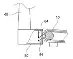
도 7은 저항조절부에서 구동벨트의 저항력을 조절하기 위한 제1 실시예를 나타내는 도면이고, 도 8은 저항조절부에서 구동벨트의 저항력을 조절하기 위한 제2 실시예를 나타내는 도면이다.FIG. 7 is a view showing a first embodiment for adjusting the resistance of the driving belt in the resistance adjusting part, and FIG. 8 is a view showing a second embodiment for adjusting the resistance of the driving belt in the resistance adjusting part.
저항조절부(80)는 제어부(70)의 조절에 의해서 구동벨트(10)의 저항력을 조절할 수 있다. 저항조절부(80)는 사용자의 신체능력이나 성별에 따른 운동능력의 차이를 고려하여 자신에게 적합하게 구동벨트(10)의 저항력을 조절하여 운동의 효율을 극대화할 수 있다.
The
도 7을 참조하면, 저항조절부(80)의 제1 실시예는 자석(82)을 이용할 수 있다. 저항조절부(80)는 구동벨트(10)의 제작시 자석(82)물질을 첨가하거나, 구동벨트(10)의 후면에 자석(82)을 연속적으로 부착하고, 구동벨트(10)와 저항조절부(80) 내부에 위치하는 자석(82)과의 거리를 조절하여 자석(82)간의 인력의 작용으로 저항력을 조절할 수 있다.
Referring to Fig. 7, the first embodiment of the
도 8을 참조하면, 저항조절부(80)의 제2 실시예는 마찰부재(84)를 이용할 수 있다. 저항조절부(80)는 복수의 마찰부재(84)가 구비되며, 마찰부재(84)가 구동벨트(10)와 접촉하여 구동벨트(10)의 저항력을 조절할 수 있다. 일실시예로, 저항조절부(80)는 복수의 마찰부재(84)가 제어부(70)의 설정에 따라 구동하며, 저항력을 증대시키기 위해서는 마찰부재(84)의 접촉면적을 증가시킬 수 있다.
Referring to Fig. 8, the second embodiment of the
도 9은 본 발명의 바람직한 실시예인 운동기구를 사용자가 탑승하였을 때, 자세를 나타내는 도면이고, 도 10의 (a) 및 (b)는 사용자의 동작에 따른 손잡이회동부의 구동 상태를 나타내기 위한 도면이다.FIG. 9 is a view showing a posture when a user wears a exercise machine, which is a preferred embodiment of the present invention. FIGS. 10A and 10B are views showing a driving state of the pull- FIG.
도 9 및 도 10을 참조하면, 본 발명의 바람직한 실시예인 운동기구(100)에 사용자가 탑승시, 양손으로 손잡이(54)를 잡고 구동벨트(10)에 발을 위치시 척추가 지면과 수평에 가까운 상태를 유지하게 된다. 사용자가 손잡이(54)를 잡은 상태로 운동시 네발 동물과 마찬가지로 척추가 좌우의 파동운동을 하게 되며, 척추의 파동운동을 통해 추진력을 얻어 구동벨트(10)를 밀게 된다. 이를 통해 종래 런닝머신을 사용할 때 발생하는 문제를 해결할 수 있다.9 and 10, when the user places the foot on the driving
또한, 척추의 파동운동을 증가시키기 위해, 구동벨트(10)의 중심부에는 운동중심선(12)이 구비될 수 있다. 발이 운동중심선(12)에 위치함으로 오른발이 전진시 오른팔은 후방으로, 왼발이 전진시 왼팔이 후방으로 운동하게 되어, 척추의 파동운동이 증가하게 된다.
In addition, in order to increase the wave motion of the vertebrae, the center line of the
이와 같이, 본 발명의 일실시예에 따른 운동기구에 의하면, 척추를 지면과 수평에 가깝게 유지시킨 상태로 걷기와 달리기를 하여 척추의 자연적 기능을 회복하여 몸의 관절과 근육체계가 자연적 기능을 할 수 있는 효과가 있다.As described above, according to the exercise apparatus according to the embodiment of the present invention, the spine can be restored to its natural function by walking and running while keeping the spine close to the ground, so that the joints and muscles of the body function naturally There is an effect that can be.
또한, 다리만이 아닌 척추도 이용하여 전방추진력을 얻음으로 기립근 강화 및 척추 유연성을 증대할 수 있는 효과가 있다.In addition, by using the spine instead of the legs, an anterior thrust can be obtained, thereby enhancing the autonomic muscles and enhancing the vertebrae flexibility.
또한, 내장기관이 부드러운 복부에 놓인 상태로 척추의 움직임에 따라 함께 출렁이도록 운동하게 되어 내장기관이 건강해 지는 효과가 있다.
Also, the internal organs are placed on the soft abdomen and move along with the movement of the vertebrae, so that the internal organs are healthy.
이상의 설명은 본 발명의 기술 사상을 예시적으로 설명한 것에 불과한 것으로서, 본 발명이 속하는 기술 분야에서 통상의 지식을 가진 자라면 본 발명의 본질적인 특성에서 벗어나지 않는 범위 내에서 다양한 수정, 변경 및 치환이 가능할 것이다. 따라서, 본 발명에 개시된 실시예 및 첨부된 도면들은 본 발명의 기술 사상을 한정하기 위한 것이 아니라 설명하기 위한 것이고, 이러한 실시예 및 첨부된 도면에 의하여 본 발명의 기술 사상의 범위가 한정되는 것은 아니다. 본 발명의 보호 범위는 아래의 청구범위에 의하여 해석되어야 하며, 그와 동등한 범위 내에 있는 모든 기술 사상은 본 발명의 권리범위에 포함되는 것으로 해석되어야 할 것이다.It will be apparent to those skilled in the art that various modifications, substitutions and substitutions are possible, without departing from the scope and spirit of the invention as disclosed in the accompanying claims. will be. Therefore, the embodiments disclosed in the present invention and the accompanying drawings are intended to illustrate and not to limit the technical spirit of the present invention, and the scope of the technical idea of the present invention is not limited by these embodiments and the accompanying drawings . The scope of protection of the present invention should be construed according to the following claims, and all technical ideas within the scope of equivalents should be construed as falling within the scope of the present invention.
10 : 구동벨트12 : 운동중심선
20 : 지지프레임
40 : 지지부
50 : 손잡이 회동부
51 : 하중조절부51a : 하중조절부관통홀
51b : 손잡이고정부
52 : 하우징
52a : 하부하우징52b : 상부하우징
53 : 회전축53a : 마모방지부
54 : 손잡이54a : 회전축관통홀
54b :볼조인트
56 : 베어링56a : 베어링관통공
58 : 충격방지부재59 : 하우징관통홀
60 : 디스플레이부
70 : 제어부
80 : 저항조절부82 : 자석
84 : 마찰부재
100 : 운동기구10: drive belt 12:
20: Support frame
40: Support
50: Handle turning section
51: load adjusting
51b: Handle fixing portion
52: Housing
52a:
53: rotating
54: handle 54a: rotation shaft through hole
54b: ball joint
56:
58: Impact preventing member 59: Housing through hole
60:
70:
80: resistance adjusting portion 82: magnet
84: Friction member
100: Fitness equipment
Claims (17)
Translated fromKorean상기 구동롤러에 감겨서 사용자의 동작에 의해서 회전하는 구동벨트;
상기 구동벨트에 인접하도록 위치하는 지지부;
상기 지지부와 연결되며, 상기 사용자의 동작에 의해서 수평방향으로 시계추 운동을 하는 손잡이를 구비하는 손잡이회동부;
를 포함하는 운동기구.A support frame having at least one drive roller;
A drive belt wound around the drive roller and rotated by a user's operation;
A support positioned adjacent the drive belt;
A knob pivoting part connected to the support part and having a knob for horizontally moving the knob by the operation of the user;
≪ / RTI >
상기 손잡이와 연결되어 상기 손잡이의 하중을 조절할 수 있는 하중조절부를 포함하는 운동기구.The method according to claim 1,
And a load adjuster connected to the knob to adjust the load of the knob.
상기 하중조절부는 탄성체 또는 유압실린더를 이용하는 것을 특징으로 하는 운동기구.3. The method of claim 2,
Wherein the load control unit uses an elastic body or a hydraulic cylinder.
상기 지지부는 상기 손잡이회동부의 높이를 조절할 수 있는 높이조절부를 더 포함하는 운동기구.The method according to claim 1,
Wherein the support portion further includes a height adjusting portion capable of adjusting a height of the handle turning portion.
상기 손잡이 회동부는,
내부에 수직방향의 회전축이 구비되며, 상기 손잡이가 관통하기 위한 하우징관통홀이 형성되는 하우징,
중앙에 상기 회전축과 결합하도록 회전축관통홀이 형성되는 손잡이
를 포함하는 운동기구.The method according to claim 1,
The handle-
A housing having a rotation shaft in a vertical direction and having a housing through hole for the handle to pass therethrough,
A handle having a rotation shaft through hole formed at the center thereof to be coupled with the rotation shaft,
≪ / RTI >
상기 하우징은 상부하우징과 하부하우징의 결합에 의해서 형성되는 것을 특징으로 하는 운동기구.6. The method of claim 5,
Wherein the housing is formed by engagement of the upper housing and the lower housing.
상기 손잡이회동부는,
상기 회전축과 연결되도록 베어링관통공이 형성되는 베어링을 더 포함하며,
상기 베어링은 상기 손잡이와 상기 하우징의 하부면 사이에 위치하는 것을 특징으로 하는 운동기구.6. The method of claim 5,
The handle-
And a bearing having a bearing through hole formed to be connected to the rotation shaft,
Wherein the bearing is located between the handle and a lower surface of the housing.
상기 베어링은 볼베어링인 것을 특징으로 하는 운동기구.8. The method of claim 7,
Wherein the bearing is a ball bearing.
상기 하우징의 내부에는 상기 손잡이가 시계추 운동시 상기 하우징관통공을 형성하는 외벽과 닿는 것을 방지하기 위한 적어도 하나의 충격방지부재가 구비되는 것을 특징으로 하는 운동기구.9. The method according to any one of claims 5 to 8,
And at least one shock-absorbing member for preventing the handle from contacting the outer wall forming the housing through-hole when the watch is in a clockwise motion.
상기 충격방지부재는 에어쿠션인 것을 특징으로 하는 운동기구.10. The method of claim 9,
Wherein the impact-preventing member is an air cushion.
상기 하우징관통홀은 구형으로 형성되며,
상기 손잡이의 중심부는 구형상의 볼조인트로 구비되고,
상기 볼조인트의 중심에 형성되는 상기 회전축관통홀은 중심부에서 외각부로 갈수록 직경이 증가하는 원형의 단면형상을 가지는 것을 특징으로 하는 운동기구.6. The method of claim 5,
The housing through-hole is formed in a spherical shape,
The center of the handle is provided with a spherical ball joint,
Wherein the rotary shaft through hole formed at the center of the ball joint has a circular cross-sectional shape increasing in diameter from a central portion to an outer peripheral portion.
상기 회전축관통홀의 중심부와 상기 회전축 사이에는 마모방지부가 구비되는 것을 특징으로 하는 운동기구.11. The method of claim 10,
And a wear prevention part is provided between a center of the rotation shaft through hole and the rotation shaft.
상기 구동벨트에는 운동중심선이 형성되는 것을 특징으로 하는 운동기구.The method according to claim 1,
And a movement center line is formed on the drive belt.
상기 사용자의 운동상태 및 운동량을 측정하는 제어부 및
상기 제어부에서 측정된 운동상태 및 운동량을 나타내는 디스플레이부를 더 포함하는 운동기구.The method according to claim 1,
A controller for measuring a motion state and a momentum of the user;
And a display unit for indicating a movement state and an exercise amount measured by the control unit.
상기 제어부의 조절에 의하여 상기 구동벨트의 저항력을 조절하는 저항조절부를 더 포함하는 운동기구.14. The method of claim 13,
And a resistance adjusting unit adjusting the resistance of the driving belt by adjusting the control unit.
상기 구동벨트에는 자석이 구비되며,
상기 저항조절부는 내부에 구비된 자석과 상기 구동벨트의 간격을 조절하여 저항을 조절하는 것을 특징으로 하는 운동기구.16. The method of claim 15,
The drive belt is provided with a magnet,
Wherein the resistance adjusting part adjusts the resistance by adjusting a gap between the magnet and the driving belt provided inside.
상기 저항조절부에는 적어도 하나의 마찰부재가 구비되어 상기 구동벨트의 저항을 조절하는 것을 특징으로 하는 운동기구.
16. The method of claim 15,
Wherein at least one frictional member is provided in the resistance regulating part to regulate a resistance of the driving belt.
Priority Applications (1)
| Application Number | Priority Date | Filing Date | Title |
|---|---|---|---|
| KR1020150046756AKR20160118519A (en) | 2015-04-02 | 2015-04-02 | Fitness Equipment |
Applications Claiming Priority (1)
| Application Number | Priority Date | Filing Date | Title |
|---|---|---|---|
| KR1020150046756AKR20160118519A (en) | 2015-04-02 | 2015-04-02 | Fitness Equipment |
Publications (1)
| Publication Number | Publication Date |
|---|---|
| KR20160118519Atrue KR20160118519A (en) | 2016-10-12 |
Family
ID=57173401
Family Applications (1)
| Application Number | Title | Priority Date | Filing Date |
|---|---|---|---|
| KR1020150046756AAbandonedKR20160118519A (en) | 2015-04-02 | 2015-04-02 | Fitness Equipment |
Country Status (1)
| Country | Link |
|---|---|
| KR (1) | KR20160118519A (en) |
Cited By (3)
| Publication number | Priority date | Publication date | Assignee | Title |
|---|---|---|---|---|
| KR20210000272U (en) | 2019-07-26 | 2021-02-03 | 박진우 | Exercise apparatus for strengthening leg rear muscle |
| KR20210001741U (en) | 2020-01-20 | 2021-07-28 | 박진우 | Exercise apparatus for strengthening leg rear muscle |
| KR102401071B1 (en)* | 2021-02-16 | 2022-05-20 | 연세대학교 원주산학협력단 | Handle for hand bikes and method of manufacturing the same |
Citations (1)
| Publication number | Priority date | Publication date | Assignee | Title |
|---|---|---|---|---|
| KR100687911B1 (en) | 2004-10-01 | 2007-03-08 | 이광덕 | Running Machine |
- 2015
- 2015-04-02KRKR1020150046756Apatent/KR20160118519A/ennot_activeAbandoned
Patent Citations (1)
| Publication number | Priority date | Publication date | Assignee | Title |
|---|---|---|---|---|
| KR100687911B1 (en) | 2004-10-01 | 2007-03-08 | 이광덕 | Running Machine |
Cited By (3)
| Publication number | Priority date | Publication date | Assignee | Title |
|---|---|---|---|---|
| KR20210000272U (en) | 2019-07-26 | 2021-02-03 | 박진우 | Exercise apparatus for strengthening leg rear muscle |
| KR20210001741U (en) | 2020-01-20 | 2021-07-28 | 박진우 | Exercise apparatus for strengthening leg rear muscle |
| KR102401071B1 (en)* | 2021-02-16 | 2022-05-20 | 연세대학교 원주산학협력단 | Handle for hand bikes and method of manufacturing the same |
Similar Documents
| Publication | Publication Date | Title |
|---|---|---|
| US7374522B2 (en) | Exercise device having a movable platform | |
| US4986261A (en) | Apparatus for performing coordinated walking motions with the spine in an unloaded state | |
| US5897474A (en) | Balancing and exercising device | |
| AU2003225051B2 (en) | Proprioception machine | |
| KR101619745B1 (en) | Ankle exercise apparatus | |
| US20100268129A1 (en) | Gait trajectory guiding device of gait rehabilitation device | |
| JP2011529352A (en) | Balance training system | |
| CN210229004U (en) | Balance training evaluation device and balance training machine | |
| WO2009084560A1 (en) | Powered exercise equipment for use in standing posture | |
| US7335172B2 (en) | Balancing and exercising device with vibrator | |
| EP1175330A1 (en) | Pedal device | |
| JP2003126191A (en) | Training device | |
| KR20160118519A (en) | Fitness Equipment | |
| JP6004557B1 (en) | Form learning type exercise assistance device | |
| US11040239B2 (en) | Smart trainer | |
| CN213099155U (en) | Lower limb training rehabilitation device for orthopedic nursing | |
| JP2008237785A (en) | Gravity load exercise device | |
| KR100850885B1 (en) | Vibrator for exercise equipment | |
| JP2020081305A (en) | Training equipment | |
| RU2531880C2 (en) | Balatron exercise machine | |
| JP2005323945A (en) | Electric training machine | |
| EP3824959A1 (en) | A multi-purpose transportable exercise device for training of balance, strength and flexibility | |
| JP2006043406A (en) | Fitness apparatus | |
| JP2012020050A (en) | Hip joint exercise device | |
| JP3071378B2 (en) | Health appliances |
Legal Events
| Date | Code | Title | Description |
|---|---|---|---|
| A201 | Request for examination | ||
| PA0109 | Patent application | Patent event code:PA01091R01D Comment text:Patent Application Patent event date:20150402 | |
| PA0201 | Request for examination | ||
| E902 | Notification of reason for refusal | ||
| PE0902 | Notice of grounds for rejection | Comment text:Notification of reason for refusal Patent event date:20151215 Patent event code:PE09021S01D | |
| E90F | Notification of reason for final refusal | ||
| PE0902 | Notice of grounds for rejection | Comment text:Final Notice of Reason for Refusal Patent event date:20160429 Patent event code:PE09021S02D | |
| E701 | Decision to grant or registration of patent right | ||
| PE0701 | Decision of registration | Patent event code:PE07011S01D Comment text:Decision to Grant Registration Patent event date:20160531 | |
| PG1501 | Laying open of application | ||
| PC1904 | Unpaid initial registration fee |