KR20160117026A - Display device - Google Patents
Display deviceDownload PDFInfo
- Publication number
- KR20160117026A KR20160117026AKR1020150045589AKR20150045589AKR20160117026AKR 20160117026 AKR20160117026 AKR 20160117026AKR 1020150045589 AKR1020150045589 AKR 1020150045589AKR 20150045589 AKR20150045589 AKR 20150045589AKR 20160117026 AKR20160117026 AKR 20160117026A
- Authority
- KR
- South Korea
- Prior art keywords
- plate
- display panel
- light
- display device
- cooling plate
- Prior art date
- Legal status (The legal status is an assumption and is not a legal conclusion. Google has not performed a legal analysis and makes no representation as to the accuracy of the status listed.)
- Withdrawn
Links
Images


Classifications
- G—PHYSICS
- G02—OPTICS
- G02F—OPTICAL DEVICES OR ARRANGEMENTS FOR THE CONTROL OF LIGHT BY MODIFICATION OF THE OPTICAL PROPERTIES OF THE MEDIA OF THE ELEMENTS INVOLVED THEREIN; NON-LINEAR OPTICS; FREQUENCY-CHANGING OF LIGHT; OPTICAL LOGIC ELEMENTS; OPTICAL ANALOGUE/DIGITAL CONVERTERS
- G02F1/00—Devices or arrangements for the control of the intensity, colour, phase, polarisation or direction of light arriving from an independent light source, e.g. switching, gating or modulating; Non-linear optics
- G02F1/01—Devices or arrangements for the control of the intensity, colour, phase, polarisation or direction of light arriving from an independent light source, e.g. switching, gating or modulating; Non-linear optics for the control of the intensity, phase, polarisation or colour
- G02F1/13—Devices or arrangements for the control of the intensity, colour, phase, polarisation or direction of light arriving from an independent light source, e.g. switching, gating or modulating; Non-linear optics for the control of the intensity, phase, polarisation or colour based on liquid crystals, e.g. single liquid crystal display cells
- G02F1/133—Constructional arrangements; Operation of liquid crystal cells; Circuit arrangements
- G02F1/1333—Constructional arrangements; Manufacturing methods
- G02F1/133382—Heating or cooling of liquid crystal cells other than for activation, e.g. circuits or arrangements for temperature control, stabilisation or uniform distribution over the cell
- G02F1/133385—Heating or cooling of liquid crystal cells other than for activation, e.g. circuits or arrangements for temperature control, stabilisation or uniform distribution over the cell with cooling means, e.g. fans
- G—PHYSICS
- G02—OPTICS
- G02F—OPTICAL DEVICES OR ARRANGEMENTS FOR THE CONTROL OF LIGHT BY MODIFICATION OF THE OPTICAL PROPERTIES OF THE MEDIA OF THE ELEMENTS INVOLVED THEREIN; NON-LINEAR OPTICS; FREQUENCY-CHANGING OF LIGHT; OPTICAL LOGIC ELEMENTS; OPTICAL ANALOGUE/DIGITAL CONVERTERS
- G02F1/00—Devices or arrangements for the control of the intensity, colour, phase, polarisation or direction of light arriving from an independent light source, e.g. switching, gating or modulating; Non-linear optics
- G02F1/01—Devices or arrangements for the control of the intensity, colour, phase, polarisation or direction of light arriving from an independent light source, e.g. switching, gating or modulating; Non-linear optics for the control of the intensity, phase, polarisation or colour
- G02F1/13—Devices or arrangements for the control of the intensity, colour, phase, polarisation or direction of light arriving from an independent light source, e.g. switching, gating or modulating; Non-linear optics for the control of the intensity, phase, polarisation or colour based on liquid crystals, e.g. single liquid crystal display cells
- G02F1/133—Constructional arrangements; Operation of liquid crystal cells; Circuit arrangements
- G02F1/1333—Constructional arrangements; Manufacturing methods
- G02F1/133382—Heating or cooling of liquid crystal cells other than for activation, e.g. circuits or arrangements for temperature control, stabilisation or uniform distribution over the cell
- G—PHYSICS
- G02—OPTICS
- G02B—OPTICAL ELEMENTS, SYSTEMS OR APPARATUS
- G02B6/00—Light guides; Structural details of arrangements comprising light guides and other optical elements, e.g. couplings
- G02B6/0001—Light guides; Structural details of arrangements comprising light guides and other optical elements, e.g. couplings specially adapted for lighting devices or systems
- G02B6/0011—Light guides; Structural details of arrangements comprising light guides and other optical elements, e.g. couplings specially adapted for lighting devices or systems the light guides being planar or of plate-like form
- G02B6/0081—Mechanical or electrical aspects of the light guide and light source in the lighting device peculiar to the adaptation to planar light guides, e.g. concerning packaging
- G02B6/0085—Means for removing heat created by the light source from the package
- G—PHYSICS
- G02—OPTICS
- G02F—OPTICAL DEVICES OR ARRANGEMENTS FOR THE CONTROL OF LIGHT BY MODIFICATION OF THE OPTICAL PROPERTIES OF THE MEDIA OF THE ELEMENTS INVOLVED THEREIN; NON-LINEAR OPTICS; FREQUENCY-CHANGING OF LIGHT; OPTICAL LOGIC ELEMENTS; OPTICAL ANALOGUE/DIGITAL CONVERTERS
- G02F1/00—Devices or arrangements for the control of the intensity, colour, phase, polarisation or direction of light arriving from an independent light source, e.g. switching, gating or modulating; Non-linear optics
- G02F1/01—Devices or arrangements for the control of the intensity, colour, phase, polarisation or direction of light arriving from an independent light source, e.g. switching, gating or modulating; Non-linear optics for the control of the intensity, phase, polarisation or colour
- G02F1/13—Devices or arrangements for the control of the intensity, colour, phase, polarisation or direction of light arriving from an independent light source, e.g. switching, gating or modulating; Non-linear optics for the control of the intensity, phase, polarisation or colour based on liquid crystals, e.g. single liquid crystal display cells
- G02F1/133—Constructional arrangements; Operation of liquid crystal cells; Circuit arrangements
- G02F1/1333—Constructional arrangements; Manufacturing methods
- G02F1/133308—Support structures for LCD panels, e.g. frames or bezels
- G—PHYSICS
- G02—OPTICS
- G02F—OPTICAL DEVICES OR ARRANGEMENTS FOR THE CONTROL OF LIGHT BY MODIFICATION OF THE OPTICAL PROPERTIES OF THE MEDIA OF THE ELEMENTS INVOLVED THEREIN; NON-LINEAR OPTICS; FREQUENCY-CHANGING OF LIGHT; OPTICAL LOGIC ELEMENTS; OPTICAL ANALOGUE/DIGITAL CONVERTERS
- G02F1/00—Devices or arrangements for the control of the intensity, colour, phase, polarisation or direction of light arriving from an independent light source, e.g. switching, gating or modulating; Non-linear optics
- G02F1/01—Devices or arrangements for the control of the intensity, colour, phase, polarisation or direction of light arriving from an independent light source, e.g. switching, gating or modulating; Non-linear optics for the control of the intensity, phase, polarisation or colour
- G02F1/13—Devices or arrangements for the control of the intensity, colour, phase, polarisation or direction of light arriving from an independent light source, e.g. switching, gating or modulating; Non-linear optics for the control of the intensity, phase, polarisation or colour based on liquid crystals, e.g. single liquid crystal display cells
- G02F1/133—Constructional arrangements; Operation of liquid crystal cells; Circuit arrangements
- G02F1/1333—Constructional arrangements; Manufacturing methods
- G02F1/1335—Structural association of cells with optical devices, e.g. polarisers or reflectors
- G02F1/133524—Light-guides, e.g. fibre-optic bundles, louvered or jalousie light-guides
- G—PHYSICS
- G02—OPTICS
- G02F—OPTICAL DEVICES OR ARRANGEMENTS FOR THE CONTROL OF LIGHT BY MODIFICATION OF THE OPTICAL PROPERTIES OF THE MEDIA OF THE ELEMENTS INVOLVED THEREIN; NON-LINEAR OPTICS; FREQUENCY-CHANGING OF LIGHT; OPTICAL LOGIC ELEMENTS; OPTICAL ANALOGUE/DIGITAL CONVERTERS
- G02F1/00—Devices or arrangements for the control of the intensity, colour, phase, polarisation or direction of light arriving from an independent light source, e.g. switching, gating or modulating; Non-linear optics
- G02F1/01—Devices or arrangements for the control of the intensity, colour, phase, polarisation or direction of light arriving from an independent light source, e.g. switching, gating or modulating; Non-linear optics for the control of the intensity, phase, polarisation or colour
- G02F1/13—Devices or arrangements for the control of the intensity, colour, phase, polarisation or direction of light arriving from an independent light source, e.g. switching, gating or modulating; Non-linear optics for the control of the intensity, phase, polarisation or colour based on liquid crystals, e.g. single liquid crystal display cells
- G02F1/133—Constructional arrangements; Operation of liquid crystal cells; Circuit arrangements
- G02F1/1333—Constructional arrangements; Manufacturing methods
- G02F1/1335—Structural association of cells with optical devices, e.g. polarisers or reflectors
- G02F1/1336—Illuminating devices
- G02F1/133615—Edge-illuminating devices, i.e. illuminating from the side
- H—ELECTRICITY
- H05—ELECTRIC TECHNIQUES NOT OTHERWISE PROVIDED FOR
- H05K—PRINTED CIRCUITS; CASINGS OR CONSTRUCTIONAL DETAILS OF ELECTRIC APPARATUS; MANUFACTURE OF ASSEMBLAGES OF ELECTRICAL COMPONENTS
- H05K7/00—Constructional details common to different types of electric apparatus
- H05K7/20—Modifications to facilitate cooling, ventilating, or heating
- H05K7/20954—Modifications to facilitate cooling, ventilating, or heating for display panels
- H05K7/2099—Liquid coolant with phase change
- G—PHYSICS
- G02—OPTICS
- G02F—OPTICAL DEVICES OR ARRANGEMENTS FOR THE CONTROL OF LIGHT BY MODIFICATION OF THE OPTICAL PROPERTIES OF THE MEDIA OF THE ELEMENTS INVOLVED THEREIN; NON-LINEAR OPTICS; FREQUENCY-CHANGING OF LIGHT; OPTICAL LOGIC ELEMENTS; OPTICAL ANALOGUE/DIGITAL CONVERTERS
- G02F1/00—Devices or arrangements for the control of the intensity, colour, phase, polarisation or direction of light arriving from an independent light source, e.g. switching, gating or modulating; Non-linear optics
- G02F1/01—Devices or arrangements for the control of the intensity, colour, phase, polarisation or direction of light arriving from an independent light source, e.g. switching, gating or modulating; Non-linear optics for the control of the intensity, phase, polarisation or colour
- G02F1/13—Devices or arrangements for the control of the intensity, colour, phase, polarisation or direction of light arriving from an independent light source, e.g. switching, gating or modulating; Non-linear optics for the control of the intensity, phase, polarisation or colour based on liquid crystals, e.g. single liquid crystal display cells
- G02F1/133—Constructional arrangements; Operation of liquid crystal cells; Circuit arrangements
- G02F1/1333—Constructional arrangements; Manufacturing methods
- G02F1/133308—Support structures for LCD panels, e.g. frames or bezels
- G02F1/13332—Front frames
- G—PHYSICS
- G02—OPTICS
- G02F—OPTICAL DEVICES OR ARRANGEMENTS FOR THE CONTROL OF LIGHT BY MODIFICATION OF THE OPTICAL PROPERTIES OF THE MEDIA OF THE ELEMENTS INVOLVED THEREIN; NON-LINEAR OPTICS; FREQUENCY-CHANGING OF LIGHT; OPTICAL LOGIC ELEMENTS; OPTICAL ANALOGUE/DIGITAL CONVERTERS
- G02F1/00—Devices or arrangements for the control of the intensity, colour, phase, polarisation or direction of light arriving from an independent light source, e.g. switching, gating or modulating; Non-linear optics
- G02F1/01—Devices or arrangements for the control of the intensity, colour, phase, polarisation or direction of light arriving from an independent light source, e.g. switching, gating or modulating; Non-linear optics for the control of the intensity, phase, polarisation or colour
- G02F1/13—Devices or arrangements for the control of the intensity, colour, phase, polarisation or direction of light arriving from an independent light source, e.g. switching, gating or modulating; Non-linear optics for the control of the intensity, phase, polarisation or colour based on liquid crystals, e.g. single liquid crystal display cells
- G02F1/133—Constructional arrangements; Operation of liquid crystal cells; Circuit arrangements
- G02F1/1333—Constructional arrangements; Manufacturing methods
- G02F1/1335—Structural association of cells with optical devices, e.g. polarisers or reflectors
- G02F1/1336—Illuminating devices
- G02F1/133628—Illuminating devices with cooling means
Landscapes
- Physics & Mathematics (AREA)
- Nonlinear Science (AREA)
- General Physics & Mathematics (AREA)
- Optics & Photonics (AREA)
- Mathematical Physics (AREA)
- Chemical & Material Sciences (AREA)
- Crystallography & Structural Chemistry (AREA)
- Thermal Sciences (AREA)
- Engineering & Computer Science (AREA)
- Microelectronics & Electronic Packaging (AREA)
- Devices For Indicating Variable Information By Combining Individual Elements (AREA)
Abstract
Translated fromKoreanDescription
Translated fromKorean본 발명은 디스플레이 장치에 관한 것으로, 상세하게는 방열 성능을 향상 시킬 수 있는 디스플레이 장치에 관한 것이다.BACKGROUND OF THE
일반적으로 디스플레이 장치는 텔레비전, 컴퓨터용 모니터, 디지털 정보 디스플레이 등과 같이 화면상에 영상을 표시하는 장치이다. 최근에는 이러한 디스플레이 장치를 옥외 또는 야외에 광고 등을 목적으로 설치하는 경우가 많아 지고 있다. 건물 외부에 배치되어 영상을 디스플레이 하는 광고판 등이 이에 속한다.In general, a display device is a device for displaying an image on a screen, such as a television, a computer monitor, a digital information display, or the like. In recent years, there have been many cases in which such a display device is installed for outdoor purposes or for outdoor purposes. And a billboard that displays images on the outside of the building.
실외 디스플레이 장치는 디스플레이 패널이 태양광에 직접 노출되는 경우 패널의 표면온도가 상승하여 열화 현상이 발생되는 문제가 있다.In the outdoor display device, when the display panel is directly exposed to the sunlight, the surface temperature of the panel rises and deterioration occurs.
또한, 디스플레이 장치는 디스플레이 패널(이하, 액정패널)과, 액정패널의 배면으로 광을 입사시키는 백라이트 유닛을 포함한다. 액정패널은 액정층을 사이에 두고 서로 마주보는 한 쌍의 기판으로 형성된다. 백라이트 유닛에는 액정패널로 광을 입사시키는 광원이 마련되고, 광원으로는 냉음극 형광관, 발광 다이오드 등이 사용되고 있다. 백라이트 유닛의 광원은 광을 발생시킬 뿐만 아니라 열도 함께 발출하여 액정을 열화 시키게 된다.Further, the display device includes a display panel (hereinafter referred to as a liquid crystal panel) and a backlight unit for inputting light to the back surface of the liquid crystal panel. The liquid crystal panel is formed of a pair of substrates facing each other with a liquid crystal layer therebetween. The backlight unit is provided with a light source that allows light to enter the liquid crystal panel, and a cold cathode fluorescent tube, a light emitting diode, or the like is used as a light source. The light source of the backlight unit generates not only light but also heat, which deteriorates the liquid crystal.
따라서, 디스플레이 장치는 백라이트 유닛의 광원에서 발생하는 열을 방출하기 위한 냉각장치를 구비한다. 냉각장치는 팬과 에어필터 등을 포함하는 구조로, 팬을 이용하여 외기를 흡입하는 동시에 액정패널 전면을 냉각하는 냉각 유로를 형성하고, 냉각 유로를 통해 태양열 및 액정패널의 열을 흡수하여 배기하도록 마련된다. Accordingly, the display device has a cooling device for emitting heat generated in the light source of the backlight unit. The cooling device has a structure including a fan and an air filter. The cooling device sucks the outside air by using a fan and forms a cooling channel for cooling the entire surface of the liquid crystal panel. The heat of the solar panel and the liquid crystal panel is absorbed and discharged through the cooling channel .
이러한 팬과 에어필터를 구비하는 방열장치는 주기적으로 필터를 교환해야 하고, 이는 높은 유지보수 비용을 발생시킨다.The heat dissipating device including such a fan and the air filter periodically needs to exchange the filter, which causes a high maintenance cost.
또한, 팬과 에어필터가 함께 배치되어야 하므로, 팬과 에어필터의 두께만큼 제품의 두께가 두꺼워져 미관상 좋지 않게 된다.Further, since the fan and the air filter are disposed together, the thickness of the product becomes thicker by the thickness of the fan and the air filter, and the appearance becomes worse.
본 발명의 일 측면은 방열 성능을 향상시킬 수 있는 디스플레이 장치를 제공한다.One aspect of the present invention provides a display device capable of improving heat radiation performance.
본 발명의 다른 측면은 면 방향 열전달 구조에 의한 냉각 성능을 향상 시킬 수 있는 디스플레이 장치를 제공한다.Another aspect of the present invention provides a display device capable of improving the cooling performance by the plane direction heat transfer structure.
본 발명의 또 다른 측면은 제품의 슬림화로 미관을 향상 시킬 수 있는 디스플레이 장치를 제공한다.Another aspect of the present invention provides a display device capable of improving the appearance by slimming a product.
본 발명의 사상에 따른 실외 디스플레이 장치는 화상을 형성하는 디스플레이 패널; 상기 디스플레이 패널에 광을 전달하는 도광판; 상기 도광판의 측면들 중 적어도 하나에 광을 조사하도록 마련되는 광원; 상기 디스플레이 패널의 후방에 위치되며, 내부 냉매의 상변화를 통해 열전달 하도록 마련되는 냉각 플레이트;를 포함한다.An outdoor display device according to an aspect of the present invention includes: a display panel for forming an image; A light guide plate for transmitting light to the display panel; A light source arranged to emit light to at least one of side surfaces of the light guide plate; And a cooling plate disposed behind the display panel and adapted to heat-transfer through a phase change of the internal refrigerant.
또한, 상기 디스플레이 패널의 전방에 위치되고, 상기 디스플레이 패널이 노출될 수 있도록 마련되는 탑 섀시를 더 포함하고, 상기 냉각 플레이트는 상기 탑 섀시의 일부와 접촉되도록 마련된다.The display device may further include a top chassis positioned in front of the display panel and adapted to expose the display panel, wherein the cooling plate is provided to be in contact with a part of the top chassis.
또한, 상기 냉각 플레이트는, 외면을 형성하도록 마련되는 제1플레이트와, 상기 제1플레이트의 내부에 형성되는 메쉬(mesh) 형태의 제2플레이트와, 상기 제2플레이트에 접하도록 형성되는 윅(wick) 형태의 제3플레이트를 포함한다.The cooling plate may include a first plate provided to form an outer surface, a second plate in the form of a mesh formed inside the first plate, and a wick formed in contact with the second plate, ) ≪ / RTI >
또한, 상기 제1플레이트는, 스테인레스 스틸(SUS)을 포함한다.In addition, the first plate includes stainless steel (SUS).
또한, 상기 제2플레이트는, 서로 다른 크기의 구멍으로 형성되는 복수의 메쉬를 포함한다.In addition, the second plate includes a plurality of meshes formed by holes of different sizes.
또한, 상기 제2플레이트는, 실리카 패드를 더 포함한다.The second plate further includes a silica pad.
또한, 상기 제1플레이트는, 설치부를 포함한다.In addition, the first plate includes a mounting portion.
또한, 상기 냉각 플레이트의 두께는 6mm 이하인 것을 특징으로 한다.The thickness of the cooling plate is 6 mm or less.
또한, 상기 제3플레이트는, 구리, 스테인레스 스틸, 알루미늄, 실리콘, 실리카(sio2) 중 어느 하나를 포함한다.The third plate may include any one of copper, stainless steel, aluminum, silicon, and silica (sio2).
또한, 상기 광원은, 상기 도광판의 사방 테두리 중 적어도 하나 이상에 배치된다.Further, the light source is disposed on at least one of the four sides of the light guide plate.
본 발명의 다른 측면에 따른 디스플레이 장치는 화상이 표시되는 디스플레이 패널; 상기 디스플레이 패널의 후방에 배치되는 도광판; 상기 도광판의 측면들 중 적어도 하나에 광을 조사하도록 마련되는 광원; 상기 디스플레이 패널의 전방에 위치되고, 상기 디스플레이 패널이 노출될 수 있도록 개구가 형성되는 탑 섀시; 상기 탑 섀시의 일부와 접촉되도록 상기 디스플레이 패널의 후방에 위치되고, 상기 광원으로부터 전달받은 열을 흡수하면서 증발하고, 방출하면서 응축되는 냉매가 수용되도록 마련되는 냉각 플레이트;를 포함한다.A display device according to another aspect of the present invention includes: a display panel on which an image is displayed; A light guide plate disposed behind the display panel; A light source arranged to emit light to at least one of side surfaces of the light guide plate; A top chassis positioned in front of the display panel and having an opening to expose the display panel; And a cooling plate positioned behind the display panel to be in contact with a part of the top chassis and adapted to evaporate while absorbing heat received from the light source and to receive refrigerant condensed while being discharged.
또한, 상기 냉각 플레이트는, 외면을 형성하도록 한 쌍으로 마련되는 제1플레이트와, 상기 제1플레이트의 내부에 형성되는 메쉬(mesh) 형태의 제2플레이트와, 상기 제2플레이트에 접하도록 형성되는 윅(wick) 형태의 제3플레이트를 포함한다.The cooling plate may include a first plate provided in a pair to form an outer surface, a second plate in the form of a mesh formed inside the first plate, and a second plate formed in contact with the second plate And a third plate in the form of a wick.
또한, 상기 제1플레이트는, 스테인레스 스틸(SUS)을 포함한다.In addition, the first plate includes stainless steel (SUS).
또한, 상기 제2플레이트는, 서로 다른 크기의 구멍으로 형성되는 복수의 메쉬를 포함한다.In addition, the second plate includes a plurality of meshes formed by holes of different sizes.
또한, 상기 제2플레이트는, 실리카 패드를 더 포함한다.The second plate further includes a silica pad.
또한, 상기 제1플레이트는, 상기 인쇄회로기판이 설치되도록 마련되는 설치부가 형성되는 것을 특징으로 한다.In addition, the first plate is characterized in that a mounting portion provided to mount the printed circuit board is formed.
또한, 상기 냉각 플레이트의 두께는 6mm 이하인 것을 특징으로 한다.The thickness of the cooling plate is 6 mm or less.
또한, 상기 제3플레이트는, 구리, 스테인레스 스틸, 알루미늄, 실리콘, 실리카(sio2) 중 어느 하나를 포함하는 것을 특징으로 한다.In addition, the third plate may include any one of copper, stainless steel, aluminum, silicon, and silica (sio2).
본 발명의 일 측면에 따른 디스플레이 장치는 면 방향 열전달 구조에 의해 방열 성능을 향상시킬 수 있는 효과가 있다.The display device according to one aspect of the present invention has an effect of improving the heat radiation performance by the plane direction heat transfer structure.
또한, 제품의 슬림화로 미관을 향상 시킬 수 있는 효과가 있다.Further, there is an effect that aesthetic appearance can be improved by slimming the product.
또한, 에어 필터가 필요 없어, 그에 따른 유지 보수 및 비용이 감소하는 비용절감의 효과가 있다.In addition, there is no need for an air filter, and there is an effect of cost reduction in which maintenance and cost are reduced.
도 1 은 본 발명의 일 실시예에 따른 디스플레이 장치를 개략적으로 나타내는 사시도,
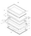
도 2 는 본 발명의 일 실시예에 따른 디스플레이 장치를 나타내는 분해 사시도,
도 3 은 본 발명의 일 실시예에 따른 디스플레이 장치의 냉각 플레이트를 나타내는 사시도,
도 4 는 본 발명의 일 실시예에 따른 냉각 플레이트의 분해 사시도,
도 5 는 본 발명의 일 실시예에 따른 냉각 플레이트의 내부 구성을 개략적으로 나타내는 도면,
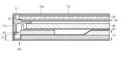
도 6 은 도 1 의 A-A’ 부분의 단면도,
도 7 은 본 발명의 일 실시예에 따른 냉각 플레이트의 설치부를 나타내는 도면,
도 8 은 본 발명의 다른 실시예에 따른 냉각 플레이트가 설치되는 디스플레이 장치를 나타내는 도면이다.1 is a perspective view schematically showing a display device according to an embodiment of the present invention,
2 is an exploded perspective view showing a display device according to an embodiment of the present invention,
3 is a perspective view showing a cooling plate of a display device according to an embodiment of the present invention,
4 is an exploded perspective view of a cooling plate according to an embodiment of the present invention,
5 is a schematic view illustrating an internal configuration of a cooling plate according to an embodiment of the present invention,
6 is a cross-sectional view taken along line A-A 'in Fig. 1,
7 is a view showing a mounting portion of a cooling plate according to an embodiment of the present invention,
8 is a view showing a display device in which a cooling plate according to another embodiment of the present invention is installed.
이하에서는 본 발명에 따른 바람직한 실시예를 첨부된 도면을 참조하여 상세히 설명한다. 한편, 하기의 설명에서 사용된 용어 "선단", "후단", "상부", "하부", "상단" 및 하단" 등은 도면을 기준으로 정의한 것이며, 이 용어에 의하여 각 구성요소의 형상 및 위치가 제한되는 것은 아니다.Hereinafter, preferred embodiments of the present invention will be described in detail with reference to the accompanying drawings. The terms "front", "rear", "upper", "lower", "upper" and "lower" used in the following description are defined with reference to the drawings. The position is not limited.
본 발명은 열원에 의해 발열하는 장치의 면방향 열전달 또는 방열하기 위한 모든 전자제품에 적용 가능하다.The present invention is applicable to all electronic products for heat transfer or heat dissipation in a plane direction of a device that generates heat by a heat source.
도 1 내지 도 2 는 본 발명의 일 실시예에 따른 실외 디스플레이 장치를 도시한 도면이다.1 and 2 are views showing an outdoor display device according to an embodiment of the present invention.
디스플레이 장치는 외부로부터 수신되는 영상 신호를 처리하고, 처리된 영상을 시각적으로 표시할 수 있는 장치이다. 이하에서는 디스플레이 장치가 실외에 설치되는 실외 디스플레이 장치(1)인 경우를 예시하고 있으나, 이에 한정되는 것은 아니다. 예를 들어, 디스플레이 장치는 모니터(Monitor), 휴대용 멀티미디어 장치, 휴대용 통신장치 등 다양한 형태로 구현할 수 있으며, 디스플레이 장치는 영상을 시각적으로 표시하는 장치라면 그 형태가 한정되지 않는다.A display device is a device that processes a video signal received from the outside and visually displays a processed video image. Hereinafter, the case of the
도 1 내지 도 2 에 도시된 바와 같이, 실외 디스플레이 장치(1)는 외관을 형성하며 전방에 개구(2a)가 형성되는 케이스(2)와, 케이스(2)의 개구(2a)에 마련되는 글라스(12)와, 케이스(2)의 내부에서 화상이 표시되도록 마련되는 디스플레이 모듈(10)을 포함한다.1 and 2, the
케이스(2)는 실외에 설치될 수 있도록 마련된다. 케이스(2)는 내부에 디스플레이 모듈(10)이 설치될 수 있도록 마련된다. 케이스(2)는 테두리를 형성할 수 있도록 상면(2b)과 양 측면(2c)을 포함한다.The
케이스(2)의 전면의 적어도 일부는 개구(2a)가 형성될 수 있다. 케이스(2)의 개구(2a)에는 글라스(12)가 설치될 수 있다. 한편, 본 실시예에서 케이스(2)의 전면은 상측 일부가 개구(2a)되어 형성되고, 전면의 적어도 일부에 글라스(12)가 마련되는 것을 예를 들어 도시하였으나, 본 발명의 사상은 이에 한정되지 않는다. 예를 들면, 전면의 전체가 개구되어 형성될 수도 있다. 이때, 전면은 전체가 글라스로 형성되게 된다.At least a part of the front surface of the
한편, 케이스(2)의 개구(2a)에 마련되는 글라스(12)는 강화 유리와 같은 충분한 강성을 가지는 투명 부재를 포함하는 투명한 재질로 형성될 수 있다.On the other hand, the
글라스(12)의 내면에는 외광에 의한 반사광을 차단하기 위한 필름(12a)이 마련될 수 있다. 필름(12a)은 편광필름 등을 포함할 수 있다. (도 6 단면도 참고)On the inner surface of the
또한, 글라스(12)는 케이스(2) 내부에 마련되는 디스플레이 모듈(10)에 대응되는 크기로 형성되어, 외부에서 케이스(2) 내부에 설치된 디스플레이 모듈(10)에서 디스플레이 되는 영상을 볼 수 있도록 되어 있다.The
케이스(2)의 하부에는 디스플레이 장치(1)를 고정하여 지지하도록 스탠드(3)가 마련될 수 있다.A
케이스(2) 내부에 마련되는 디스플레이 모듈(10)은 디스플레이 패널(20)과, 디스플레이 패널(20)의 후방에 마련되어 디스플레이 패널(20)에 광을 조사하도록 마련되는 백 라이트 유닛(50)을 포함한다.The
디스플레이 모듈(10)은 디스플레이 패널(20)의 전면에 배치되는 탑 섀시(11)와, 디스플레이 패널(20)을 지지하도록 그 내부에 마련되는 미드 몰드(13)를 포함할 수 있다.The
탑 섀시(11)는 사각 링 형상으로 형성되며, 영상이 표시되는 디스플레이 패널(20)과 동일한 면에 마련되어 디스플레이 패널(20)의 엣지 부분이 외부로 노출되는 것을 방지한다.The
미드 몰드(13)는 디스플레이 패널(20), 광학 부재(40) 및 백 라이트 유닛(50)을 지지하도록 마련된다. 미드 몰드(13)는 디스플레이 패널(20), 광학 부재(40)를 지지하도록 마련된다.The
디스플레이 패널(20)은 액정층(liquid crystal layer) (미도시), 투명 전극층(미도시), 투명 기판(미도시) 및 컬러 필터(color filter array) (미도시)을 포함할 수 있다. 액정층에는 적정량의 액정이 마련된다. 액정층의 양측에는 액정층에 변환하는 전기장을 형성하기 위한 한 쌍의 투명 전극층이 마련된다. 한 쌍의 투명 전극층 사이에 입력되는 전압에 따라 액정층에 인가되는 전기장이 변화한다.The
이와 같은 투명 전극층은 게이트 라인(미도시), 데이터 라인(미도시) 및 박막 트랜지스터(Thin Film Transistor, TFT)를 포함할 수 있다.The transparent electrode layer may include a gate line (not shown), a data line (not shown), and a thin film transistor (TFT).
한 쌍의 투명 기판(미도시)은 디스플레이 패널(20)의 외관을 형성하며, 액정층 및 투명 전극층을 보호한다. 이와 같은 투명 기판은 광 투과성이 좋은 강화 유리 또는 투명 필름으로 구성될 수 있다.A pair of transparent substrates (not shown) form the appearance of the
이처럼, 디스플레이 패널(20)은 아래에서 설명할 백 라이트 유닛(50)으로부터 생성된 광을 차단 또는 투과시킴으로써 영상을 생성하도록 마련된다. 구체적으로, 디스플레이 패널(20)을 구성하는 각각의 화소가 백 라이트 유닛(50)의 광을 차단하거나 투과시킴으로써 다양한 색상의 영상이 생성되게 된다.As described above, the
구동 회로(30)는 디스플레이 패널(20)을 구동하기 위한 구동 신호를 디스플레이 패널(20)에 제공한다. 구동 회로(30)는 데이터 구동 회로(31)와 게이트 구동 회로(32)를 포함할 수 있다. 게이트 구동 회로(32)는 디스플레이 패널(20)의 게이트 라인(미도시)과 연결되어 게이트 라인에 게이트 신호를 전달할 수 있다. 또한, 데이터 구도 회로(31)는 디스플레이 패널(20)의 데이터 라인(미도시)과 연결되어 데이터 라인에 데이터 신호를 전달할 수 있다.The driving
백 라이트 유닛(50)은 디스플레이 패널(20)의 후방에 설치되어, 디스플레이 패널(20)이 영상을 생성하기 위한 광을 생성한다.The
백 라이트 유닛(50)은 디스플레이 패널(20)에 광을 조사하도록 마련되는 광원(51)과, 도광판(Light Guide Plate, LGP) (48)을 포함한다.The
광학 부재(40)는 디스플레이 장치(1)의 시야각을 넓히고 디스플레이 장치(1)의 휘도를 증가시키기 위하여 광을 굴절 또는 산란시킨다.The
광학 부재(40)는 다양한 시트를 포함할 수 있다. 예를 들어, 광학 부재(40)는 확산 시트(41), 프리즘 시트(42), 보호 시트(43), 및 휘도 향상 필름(Double Brightness Enhance File, DBEF) (44)을 포함할 수 있다.The
확산 시트(41)는 백 라이트 유닛(50)으로부터 출사된 광을 면을 따라 확산시켜 디스플레이 장치(1)의 화면 전체적으로 색상 및 밝기가 균일하게 보이도록 한다.The
확산 시트(41)는 도광판(48)으로부터 출사되는 광을 출사 방향과 수직한 방향으로 확산시킨다.The
다시 말해, 확신 시트(51)는 백 라이트 유닛(50)으로부터 출사된 광을 확산시켜 전체 면의 밝기를 균일하게 유지시킨다.In other words, the
확산 시트(41)를 통과한 광은 확산 시트(41)의 면과 수직한 방향으로 확산됨으로써 휘도가 급격히 감소한다. 프리즘 시트(42)는 확산 시트(41)에 의하여 확산된 광을 굴절 또는 집광시킴으로써 휘도를 증가시킨다.The light having passed through the
또한, 프리즘 시트(42)는 삼각 프리즘 형상의 프리즘 패턴을 포함하고, 이 프리즘 패턴은 복수 개가 인접 배열되어 복수 개의 띠 모양을 이룬다. 즉, 프리즘 패턴은 산과 골이 반복되는 패턴으로 열을 지어 디스플레이 패널(10)을 향하여 돌출되어 형성된다.The
보호 시트(43)는 백 라이트 유닛(50)에 포함된 각종 구성 부품을 외부의 충격이나 이물질의 유입으로부터 보호한다. 특히, 프리즘 시트(42)는 스크래치(scratch)가 발생하기 쉬우며, 보호 시트(43)는 프리즘 시트(42)의 스크래치를 방지할 수 있다.The
휘도 향상 필름(44)은 편광 필름의 일종으로 반사형 편광 필름이라고도 한다. 이러한 휘도 향상 필름(44)은 백 라이트 유닛(50)으로부터 출사된 광 가운데 휘도 향상 필름(44)의 편광 방향과 평행한 방향의 편광을 투과시키고, 휘도 향상 필름(44)의 편광 방향과 다른 방향의 편광을 반사한다.The
광원(51)은 도광판(48)의 좌측 과 우측에 각각 마련되어, 도광판(48)을 향하여 광을 출력한다. 광원(51)은 발열량이 적은 엘이디(Light Emitting Diode, LED) 또는 냉음극관(Cold Cathode Fluorescence Lamp, CCFL)를 채용할 수 있다.The
광원(51)은 플렉서블한 재질로 형성되는 인쇄회로기판(52)에 결합되어 디스플레이 패널(20)의 엣지(edge) 부분에 마련될 수 있다.The
이러한, 엣지형 백 라이트 유닛(50)에서 도광판(48)은 측면으로부터 입사되는 광의 진행 방향을 변경하여 전면을 향하여 광을 출사한다. 이때, 광의 진행 방향을 변경하기 위하여 도광판(48)의 전면에는 복수의 볼록한 줄무늬가 형성될 수 있으며, 도광판(48)의 후면에는 복수의 도트(dot)가 형성될 수도 있다.In the edge-
한편, 디스플레이 장치(1)는 디스플레이 패널(20)에 신호를 인가하여 디스플레이 모듈(10)을 가동시키도록 마련되는 적어도 하나 이상의 회로기판(49)이 마련된다. 회로기판(49)에는 상호 정보를 주고 받으며 기능을 수행하는 CPU와 SMP 등 다양한 제어수단이 장착되고, 이러한 제어수단은 발열체로서 열을 발생시킨다.The
디스플레이 모듈(10)은 이러한 광원과 제어수단에 의해 내부에서 발생되는 열과 외부의 태양광에 의해 발생되는 열에 의해 열화 될 수 있다.The
또한, 디스플레이 모듈(10)은 백 라이트 유닛(50)의 광원(51)으로 채용되는 복수의 발광 다이오드(LED)에 의해 발생하는 열에 의해 열화 될 수 있다. 이러한 열화는 디스플레이 장치(1)의 수명을 단축 시킬 수 있다.In addition, the
따라서, 본 발명 실시예에서 디스플레이 모듈(10)이 마련되는 디스플레이 장치(1)는 그 내부의 온도가 일정 범위 내에서 유지될 수 있도록 마련되는 냉각 플레이트(100)를 포함한다.Therefore, in the embodiment of the present invention, the
냉각 플레이트(100)는 디스플레이 모듈(10)의 후방에서 디스플레이 모듈(10)의 후면을 형성하도록 마련될 수 있다.The
냉각 플레이트(100)는 탑 섀시(11)의 적어도 일부와 접촉하여 결합될 수 있다. 일례로 탑 섀시(11)의 측면부 내측(11a)은 후술하게 되는 냉각 플레이트(100)에 형성되는 설치부(150)와 접촉하여 조립될 수 있다.The
또한, 냉각 플레이트(100)는 미드 몰드(13)에 결합될 수 있다. 냉각 플레이트(100)의 설치부(150)는 미드 몰드(13)에 볼트 등의 체결부재(미도시)를 통해 결합될 수 있다.In addition, the
도 3 은 본 발명의 일 실시예에 따른 디스플레이 장치의 냉각 플레이트를 나타내는 사시도이고, 도 4 는 본 발명의 일 실시예에 따른 냉각 플레이트의 분해 사시도이며, 도 5 는 본 발명의 일 실시예에 따른 냉각 플레이트의 내부 구성을 개략적으로 나타내는 도면이고, 도 6 은 도 1 의 A-A’ 부분의 단면도이며, 도 7 은 본 발명의 일 실시예에 따른 냉각 플레이트의 설치부를 나타내는 도면이다.FIG. 3 is a perspective view showing a cooling plate of a display device according to an embodiment of the present invention, FIG. 4 is an exploded perspective view of a cooling plate according to an embodiment of the present invention, and FIG. FIG. 6 is a cross-sectional view taken along line A-A 'of FIG. 1, and FIG. 7 is a view showing a mounting portion of a cooling plate according to an embodiment of the present invention.
도 3 내지 도 5 에 도시된 바와 같이, 냉각 플레이트(100)는 판 형상으로 형성될 수 있다. 판 형상의 냉각 플레이트(100)는 디스플레이 모듈(10)의 후방에 배치된다. 냉각 플레이트(100)는 디스플레이 모듈(10)의 후면을 형성하도록 마련된다.3 to 5, the
냉각 플레이트(100)는 디스플레이 패널(20)에 대응되는 형상 및 크기로 형성된다.The
냉각 플레이트(100)는 디스플레이 모듈(10)의 디스플레이 패널(20) 및 백 라이트 유닛(50) 등의 고 발열원의 열을 효율적으로 분산 및 방열하도록 마련된다.The
냉각 플레이트(100)는 외면을 형성하도록 마련되는 제1플레이트(110)와, 제1플레이트(110)의 내부에 마련되며, 메쉬(mesh) 형태로 형성되는 제2플레이트(120)와, 제1플레이트(110)의 내부에 마련되며, 윅(wick) 형태로 형성되는 제3플레이트(130)를 포함할 수 있다.The
또한, 냉각 플레이트(100)는 그 내부에서 상변화 가능하게 마련되는 냉매(작동 유체,미도시)를 더 포함한다. 냉매는 열을 발생시키는 열원에 접촉되도록 설치되면, 열원 부근에 있는 냉매는 가열되어 기화된 후 상대적으로 온도가 낮은 영역으로 확산하게 된다. 그러면 기화된 냉매는 열을 외부로 방출하면서 다시 응축되어 액체 상태가 되고 다시 본래의 위치로 복귀하게 된다.Further, the
이처럼 냉각 플레이트(100) 내부에서 이루어지는 냉매의 순환 메카니즘에 의해 열원으로부터 발생된 열은 외부로 방출되며, 이에 따라 디스플레이 모듈(10)의 온도가 적정한 선에서 유지될 수 있게 된다.The heat generated from the heat source is discharged to the outside by the circulation mechanism of the refrigerant inside the
이때, 냉각 플레이트(100)의 제1플레이트(110)는 스테인리스 스틸(sus)로 형성된다. 스테인리스 스틸(sus) 재질은 냉각 플레이트(100)의 대형화시 강도 확보 및 평탄도를 확보하도록 한다.At this time, the
제1플레이트(110)는 디스플레이 패널(20) 및 백 라이트 유닛(50)의 후방에 배치된다. 제1플레이트(110)는 디스플레이 모듈(10)의 후면을 형성할 수 있다.The
제1플레이트(110)는 전면(110a)과 후면(110b)을 형성하도록 두 개가 한 쌍으로 마련될 수 있다. 제1플레이트(110)의 전면(110a)과 후면(110b)은 서로 결합되어 마련된다.The
제1플레이트(110)의 내부에는 메쉬 형태의 제2플레이트(120)와 윅 형태의 제3플레이트(130)가 서로 적층되어 마련될 수 있다.In the
제2플레이트(120)는 서로 다른 크기의 구멍(121a, 122a)으로 형성되는 복수의 메쉬(121,122,123)를 포함한다.The
메쉬(121,122,123)는 제1직경(d1)의 구멍(121a)으로 형성되는 제1메쉬(121)와, 제2직경(d2)의 구멍(122a)으로 형성되는 제2메쉬(122)와, 미세 구멍(미도시)으로 형성되는 제3메쉬(123)를 포함한다.The meshes 121,122 and 123 include a
제1메쉬(121)와, 제2메쉬(122)와, 제3메쉬(123)의 구멍(121a, 212a)들은 각각 복수개로 형성된다.The
한편, 제2메쉬(122)의 제2직경(d2)은 제1메쉬(121)의 제1직경(d1) 보다 작게 형성될 수 있다. 또한, 제3메쉬(123)의 구멍의 직경은 제2메쉬(122)의 제2직경(d2) 보다 작게 형성될 수 있다.The second diameter d2 of the
따라서, 복수의 메쉬(121,122,123)는 서로 다른 직경의 구멍(121a, 122a)으로 형성되는 복수의 메쉬(121,122,123)가 적층된 형태로 형성되게 된다.Accordingly, the plurality of
이러한, 메쉬(121,122,123)의 적층 구조는 증기의 통로 및 강성 유지를 위해 형성될 수 있다.Such a laminated structure of the
제2플레이트(120)는 실리카 패드(124)를 더 포함할 수 있다. 실리카 패드(124)는 냉매 플레이트(100) 내부의 냉매 보유를 위해 마련될 수 있다.The
한편, 원활한 냉매의 공급을 위해 냉각 플레이트(100)의 엣지부(edge)에는 실리카 더미가 충진되도록 형성될 수 있다.On the other hand, an edge of the
제3플레이트(123)는 윅 구조체(wick structure)로 냉매의 효율적인 순환을 위해 형성된다. 제3플레이트(123)는 냉매를 보유하고 있다가 열에 의해 기화되어 내부 공간(S)을 통해 사방으로 확산 및 방출하고 응축된다.The
한편, 도 6 내지 도 7 에 도시된 바와 같이, 냉각 플레이트(100)는 열원의 위치에 의해 두께가 다르게 형성될 수도 있다.6 to 7, the
냉각 플레이트(100)는 상기와 같이 제1플레이트(110)와 제2플레이트(120), 그리고 제3플레이트(130)를 포함하여 형성되는 제1두께(t1)로 형성될 수 있다.The
또한, 냉각 플레이트(100)는 제1플레이트(110)와 제2플레이트(120)를 포함하여 형성되는 제2두께(t2)로 형성될 수도 있다.The
이때, 제1두께(t1)는 제2두께(t2) 보다 제3플레이트(130)의 두께만큼 두껍게 형성될 수 있다.At this time, the first thickness t1 may be formed thicker than the second thickness t2 by the thickness of the
냉각 플레이트(100)는 열원의 위치 및 설계에 따라 다양한 두께를 형성하도록 할 수 있다. 예를 들면, 냉각 플레이트(100)는 그 중심부는 제1두께(t1)로 형성하고, 외곽 테두리는 제2두께(t2)로 형성할 수 있다.The
한편, 본 실시예의 냉각 플레이트(100)는 스테인리스 스틸(SUS) 재질로 형성되어, 강도 및 평탄도를 향상 시킬 수 있다.On the other hand, the
또한, 냉각 플레이트(100)에는 회로기판(49) 또는 인쇄회로기판(52)등의 별도의 부재가 설치될 수 있도록 설치부(150)가 형성될 수 있다. 설치부(150)는 스테인리스 스틸 재질의 냉각 플레이트(100)에 일체로 형성될 수 있다.The mounting
설치부(150)는 냉각 플레이트(100)의 테두리가 디스플레이 패널(20) 방향을 향해 절곡 형성되는 설치 프레임(150a)과, 설치 프레임(150a)에 관통 형성되는 설치홀(151), 그리고 냉각 플레이트(100)의 면부에 형성되는 설치홈(152)을 포함할 수 있다.The mounting
이러한, 설치부(150)는 디스플레이 모듈(10) 내부에 마련되는 회로기판(49) 또는 인쇄회로기판(52) 등이 설치 가능하도록 마련된다. 예를 들어, 설치부(150)의 설치 프레임(150a)에 형성되는 설치홀(151)은 디스플레이 장치(1)의 외관을 형성하는 케이스(2)와 결합하도록 마련될 수 있다.The mounting
본 발명의 실시예에서 설치부(150)는 냉각 플레이트(100)와 일체로 형성되는 것을 예를 들어 도시하였으나, 본 발명의 사상은 이에 한정되지 않는다. 예를 들면, 냉각 플레이트의 설치부는 용접 등의 공정을 통해 형성될 수도 있다.Although the mounting
상기와 같은 구성의 냉각 플레이트(100)의 제조 방법은, 제1플레이트(110)를 형성하기 위해 스테인리스 스틸 재질의 판재를 프레스 공정한다. 이때, 상부는 드로밍 또는 트리밍 하고, 하부는 블랭킹하며, 사이드 바는 피어싱 및 노칭 공정을 한다.In the method of manufacturing the
스테인리스 스틸 재질의 판재는 터널식 세척 공정을 통해 세척한다. 이때 세척제는 TC 대체 용제를 포함할 수 있다.Stainless steel plate is cleaned by tunnel cleaning process. The cleaning agent may include a TC replacement solvent.
세척을 완료한 스테인리스 스틸 재질의 판재는 2단 스터드 용접과, PEM NUT 용접을 차례로 하여 제1플레이트(110)를 형성한다.The cleaned stainless steel plate forms the
제1플레이트(110)의 내부에 심재를 적층하고, 스터드 용접과 프레임 용접을 한다.A core material is laminated inside the
제1플레이트(110)를 진공처리 한다. 이때 진공도는 10-2 ~10-3 torr 로 한다.The
진공이 완료된 냉각 플레이트(100)는 열분포 검사를 하고, 2~3 일의 에이징 후에 2차 열분포 검사를 하여 포장 및 적재될 수 있다.The vacuum-completed
도 8 은 본 발명의 다른 실시예에 따른 냉각 플레이트가 설치되는 디스플레이 장치를 나타내는 도면이다.8 is a view showing a display device in which a cooling plate according to another embodiment of the present invention is installed.
도 8 에 도시된 바와 같이, 본 발명의 다른 실시예에 따른 디스플레이 모듈(10)은 디스플레이 패널(20)과, 디스플레이 패널(20)의 후방에 마련되어 디스플레이 패널(20)에 광을 조사하도록 마련되는 백 라이트 유닛(50)을 포함한다.8, the
백 라이트 유닛(50)은 디스플레이 패널(20)의 후방에 설치되어, 디스플레이 패널(20)이 영상을 생성하기 위한 광을 생성한다.The
백 라이트 유닛(50)은 디스플레이 패널(20)에 광을 조사하도록 마련되는 광원(51)과, 광원(51)으로부터 생성된 광을 면광(面光, sheet light)으로 변환하는 도광판(Light Guide Plate, LGP)(48), 도광판(60)의 후면에 마련되어 도광판(60)으로부터 출력되는 광을 반사시키는 반사 시트(Reflector Sheet) (45) 및 도광판(48)으로부터 광을 입력받아 백색광(다양한 색상의 광이 혼합된 광)을 출력하는 양자점 시트(Quantum Dot Sheet) (44)를 포함한다.The
광원(51)은 도광판(48)의 사방 테두리에 각각 마련된다. 광원(51)은 도광판(48)의 좌측과 우측, 그리고 상측과 하측에 각각 배치될 수 있다.The
광원(51)은 디스플레이 패널(20)의 사방 엣지(edge) 부분에 마련된다.The
한편, 디스플레이 장치(1)는 디스플레이 패널(20)에 신호를 인가하여 디스플레이 모듈(10)을 가동시키도록 마련되는 적어도 하나 이상의 회로기판(49)이 마련된다. 회로기판(49)에는 상호 정보를 주고 받으며 기능을 수행하는 CPU와 SMP 등 다양한 제어수단이 장착되고, 이러한 제어수단은 발열체로서 열을 발생시킨다.The
디스플레이 장치(1)는 이러한 광원(51)과 제어수단에 의해 내부에서 발생되는 열에 의해 열화 될 수 있다.The
따라서, 디스플레이 모듈(10)은 내부의 온도가 일정 범위 내에서 유지될 수 있도록 마련되는 냉각 플레이트(100)를 포함할 수 있다. 냉각 플레이트(100)는 디스플레이 모듈(10)의 후방에서 디스플레이 모듈(0)의 후면을 형성하도록 마련될 수 있다.Accordingly, the
냉각 플레이트(100)는 대면적의 열전도를 통해 고발열을 흡수 및 방열할 수 있어 냉각의 효율을 높일 수 있다. 구체적인 냉각 플레이트(100)의 구성은 상기 일실시예와 동일하므로 중복되는 설명은 생략한다.The
이상과 같이 본 발명의 이해를 위해 그 실시예를 기술하였으나, 당업자라면 알 수 있듯이 본 발명은 본 명세서에 기술된 특정 실시예를 한정하는 것이 아니라, 본 발명의 범주를 벗어나지 않는 범위에서 다양하게 변형, 변경 및 대체될 수 있다.While the present invention has been particularly shown and described with reference to exemplary embodiments thereof, it is to be understood that the invention is not limited to the disclosed exemplary embodiments, but, on the contrary, is intended to cover various modifications and equivalent arrangements included within the spirit and scope of the appended claims. , Changed and replaced.
1 : 디스플레이 장치10 : 디스플레이 모듈
11 : 탑 섀시20 : 디스플레이 패널
40 : 광학부재50 : 백 라이트 유닛
51 : 광원52 : 인쇄회로기판
100 : 냉각 플레이트110 : 제1플레이트
120 : 제2플레이트130 : 제3플레이트
150 : 설치부1: display device 10: display module
11: Top chassis 20: Display panel
40: optical member 50: backlight unit
51: light source 52: printed circuit board
100: cooling plate 110: first plate
120: second plate 130: third plate
150:
Claims (18)
Translated fromKorean상기 디스플레이 패널에 광을 전달하는 도광판;
상기 도광판의 측면들 중 적어도 하나에 광을 조사하도록 마련되는 광원;
상기 디스플레이 패널의 후방에 위치되며, 내부 냉매의 상변화를 통해 열전달 하도록 마련되는 냉각 플레이트;
를 포함하는 디스플레이 장치.A display panel for forming an image;
A light guide plate for transmitting light to the display panel;
A light source arranged to emit light to at least one of side surfaces of the light guide plate;
A cooling plate disposed at a rear side of the display panel and adapted to heat-transfer through a phase change of the internal refrigerant;
.
상기 디스플레이 패널의 전방에 위치되고, 상기 디스플레이 패널이 노출될 수 있도록 마련되는 탑 섀시를 더 포함하고,
상기 냉각 플레이트는 상기 탑 섀시의 일부와 접촉되도록 마련되는 것을 특징으로 하는 디스플레이 장치.The method according to claim 1,
Further comprising a top chassis positioned in front of the display panel and provided so that the display panel can be exposed,
And the cooling plate is provided to be in contact with a part of the tower chassis.
상기 냉각 플레이트는,
외면을 형성하도록 마련되는 제1플레이트와,
상기 제1플레이트의 내부에 형성되는 메쉬(mesh) 형태의 제2플레이트와,
상기 제2플레이트에 접하도록 형성되는 윅(wick) 형태의 제3플레이트를 포함하는 것을 특징으로 하는 디스플레이 장치.The method according to claim 1,
Wherein the cooling plate comprises:
A first plate provided to form an outer surface,
A second plate in the form of a mesh formed inside the first plate,
And a third plate in the form of a wick formed in contact with the second plate.
상기 제1플레이트는, 스테인레스 스틸(SUS)을 포함하는 것을 특징으로 하는 디스플레이 장치.The method of claim 3,
Wherein the first plate comprises stainless steel (SUS).
상기 제2플레이트는,
서로 다른 크기의 구멍으로 형성되는 복수의 메쉬를 포함하는 것을 특징으로 하는 디스플레이 장치.The method of claim 3,
Wherein the second plate
And a plurality of meshes formed by holes of different sizes.
상기 제2플레이트는,
실리카 패드를 더 포함하는 것을 특징으로 하는 디스플레이 장치.The method of claim 3,
Wherein the second plate
Further comprising a silica pad.
상기 제1플레이트는,
설치부를 포함하는 것을 특징으로 하는 디스플레이 장치.The method of claim 3,
Wherein the first plate includes:
And a mounting portion.
상기 냉각 플레이트의 두께는 6mm 이하인 것을 특징으로 하는 디스플레이 장치.The method according to claim 1,
Wherein the thickness of the cooling plate is 6 mm or less.
상기 제3플레이트는,
구리, 스테인레스 스틸, 알루미늄, 실리콘, 실리카(sio2) 중 어느 하나를 포함하는 것을 특징으로 하는 디스플레이 장치.The method of claim 3,
Wherein the third plate comprises:
Any one of copper, stainless steel, aluminum, silicon, silica (sio2) display device comprising: a.
상기 광원은,
상기 도광판의 사방 테두리 중 적어도 하나 이상에 배치되는 것을 특징으로 하는 디스플레이 장치.The method according to claim 1,
The light source includes:
Wherein the light guide plate is disposed on at least one of the four sides of the light guide plate.
상기 디스플레이 패널의 후방에 배치되는 도광판;
상기 도광판의 측면들 중 적어도 하나에 광을 조사하도록 마련되는 광원
상기 디스플레이 패널의 전방에 위치되고, 상기 디스플레이 패널이 노출될 수 있도록 개구가 형성되는 탑 섀시;
상기 탑 섀시의 일부와 접촉되도록 상기 디스플레이 패널의 후방에 위치되고, 상기 광원으로부터 전달받은 열을 흡수하면서 증발하고, 방출하면서 응축되는 냉매가 수용되도록 마련되는 냉각 플레이트;
를 포함하는 것을 특징으로 하는 디스플레이 장치.A display panel on which an image is displayed;
A light guide plate disposed behind the display panel;
A light source provided to irradiate at least one of the side surfaces of the light guide plate with light,
A top chassis positioned in front of the display panel and having an opening to expose the display panel;
A cooling plate positioned behind the display panel to be in contact with a part of the tower chassis and adapted to receive refrigerant while being evaporated while absorbing heat received from the light source and condensed while being discharged;
And a display device.
상기 냉각 플레이트는,
외면을 형성하도록 한 쌍으로 마련되는 제1플레이트와,
상기 제1플레이트의 내부에 형성되는 메쉬(mesh) 형태의 제2플레이트와,
상기 제2플레이트에 접하도록 형성되는 윅(wick) 형태의 제3플레이트를 포함하는 것을 특징으로 하는 디스플레이 장치.12. The method of claim 11,
Wherein the cooling plate comprises:
A first plate provided in a pair so as to form an outer surface,
A second plate in the form of a mesh formed inside the first plate,
And a third plate in the form of a wick formed in contact with the second plate.
상기 제1플레이트는, 스테인레스 스틸(SUS)을 포함하는 것을 특징으로 하는 디스플레이 장치.12. The method of claim 11,
Wherein the first plate comprises stainless steel (SUS).
상기 제2플레이트는,
서로 다른 크기의 구멍으로 형성되는 복수의 메쉬를 포함하는 것을 특징으로 하는 디스플레이 장치.12. The method of claim 11,
Wherein the second plate
And a plurality of meshes formed by holes of different sizes.
상기 제2플레이트는,
실리카 패드를 더 포함하는 것을 특징으로 하는 디스플레이 장치.15. The method of claim 14,
Wherein the second plate
Further comprising a silica pad.
상기 제1플레이트는,
상기 인쇄회로기판이 설치되도록 마련되는 설치부가 형성되는 것을 특징으로 하는 디스플레이 장치.13. The method of claim 12,
Wherein the first plate includes:
And a mounting portion provided to mount the printed circuit board.
상기 냉각 플레이트의 두께는 6mm 이하인 것을 특징으로 하는 디스플레이 장치.12. The method of claim 11,
Wherein the thickness of the cooling plate is 6 mm or less.
상기 제3플레이트는,
구리, 스테인레스 스틸, 알루미늄, 실리콘, 실리카(sio2) 중 어느 하나를 포함하는 것을 특징으로 하는 디스플레이 장치.
13. The method of claim 12,
Wherein the third plate comprises:
Any one of copper, stainless steel, aluminum, silicon, silica (sio2) display device comprising: a.
Priority Applications (4)
| Application Number | Priority Date | Filing Date | Title |
|---|---|---|---|
| KR1020150045589AKR20160117026A (en) | 2015-03-31 | 2015-03-31 | Display device |
| EP16160706.4AEP3076230A1 (en) | 2015-03-31 | 2016-03-16 | Cooling system of a display |
| CN201610186646.2ACN106019667A (en) | 2015-03-31 | 2016-03-29 | Display device |
| US15/086,292US20160291397A1 (en) | 2015-03-31 | 2016-03-31 | Display device |
Applications Claiming Priority (1)
| Application Number | Priority Date | Filing Date | Title |
|---|---|---|---|
| KR1020150045589AKR20160117026A (en) | 2015-03-31 | 2015-03-31 | Display device |
Publications (1)
| Publication Number | Publication Date |
|---|---|
| KR20160117026Atrue KR20160117026A (en) | 2016-10-10 |
Family
ID=55628754
Family Applications (1)
| Application Number | Title | Priority Date | Filing Date |
|---|---|---|---|
| KR1020150045589AWithdrawnKR20160117026A (en) | 2015-03-31 | 2015-03-31 | Display device |
Country Status (4)
| Country | Link |
|---|---|
| US (1) | US20160291397A1 (en) |
| EP (1) | EP3076230A1 (en) |
| KR (1) | KR20160117026A (en) |
| CN (1) | CN106019667A (en) |
Cited By (2)
| Publication number | Priority date | Publication date | Assignee | Title |
|---|---|---|---|---|
| WO2022196838A1 (en)* | 2021-03-15 | 2022-09-22 | 엘지전자 주식회사 | Display device |
| WO2025048165A1 (en)* | 2023-09-01 | 2025-03-06 | 삼성전자 주식회사 | Display apparatus |
Families Citing this family (9)
| Publication number | Priority date | Publication date | Assignee | Title |
|---|---|---|---|---|
| JP6505233B2 (en)* | 2015-09-03 | 2019-04-24 | 堺ディスプレイプロダクト株式会社 | Display device |
| JP6361939B2 (en)* | 2016-03-08 | 2018-07-25 | パナソニックIpマネジメント株式会社 | Display device |
| US10321615B2 (en)* | 2016-06-16 | 2019-06-11 | Microsoft Technology Licensing, Llc | Display module with integrated thermal management structure |
| KR102624006B1 (en)* | 2016-12-20 | 2024-01-11 | 삼성디스플레이 주식회사 | Display Apparatus |
| CN107027271B (en)* | 2017-04-28 | 2019-04-30 | 深圳市华星光电技术有限公司 | Liquid crystal display television cooling system and LCD TV |
| US12326631B2 (en)* | 2020-12-23 | 2025-06-10 | Intel Corporation | Display with a distributed nano light emitting diode backlight |
| CN216079719U (en)* | 2021-06-25 | 2022-03-18 | 广东英维克技术有限公司 | Radiator in TV LED lamp area |
| USD999176S1 (en)* | 2021-07-29 | 2023-09-19 | Ohc Ip Holdings, Llc | Outdoor electronics enclosure |
| DE102022205049A1 (en)* | 2022-05-20 | 2023-11-23 | Continental Automotive Technologies GmbH | Electronic device and means of transport |
Family Cites Families (10)
| Publication number | Priority date | Publication date | Assignee | Title |
|---|---|---|---|---|
| WO2005053371A1 (en)* | 2003-11-27 | 2005-06-09 | Ls Cable Ltd. | Flat plate heat transfer device |
| KR101097486B1 (en)* | 2004-06-28 | 2011-12-22 | 엘지디스플레이 주식회사 | back light unit of liquid crystal display device |
| DE102005063433B4 (en)* | 2004-10-29 | 2009-11-26 | Lg Display Co., Ltd. | Backlight unit and liquid crystal display device |
| US20070211182A1 (en)* | 2006-03-10 | 2007-09-13 | Luminus Devices, Inc. | Optical system thermal management methods and systems |
| JP2007266153A (en)* | 2006-03-28 | 2007-10-11 | Sony Corp | Plate-shape heat transport device and electronic device |
| KR20080020880A (en)* | 2006-09-01 | 2008-03-06 | 삼성전자주식회사 | Display |
| JP4557055B2 (en)* | 2008-06-25 | 2010-10-06 | ソニー株式会社 | Heat transport device and electronic equipment |
| JP4706754B2 (en)* | 2008-12-24 | 2011-06-22 | ソニー株式会社 | Heat transport device and electronic equipment |
| KR100933631B1 (en)* | 2009-08-18 | 2009-12-23 | 삼성전자주식회사 | Back light assembly and liquid crystal display including the same |
| KR20120012150A (en)* | 2010-07-30 | 2012-02-09 | 엘지디스플레이 주식회사 | LCD Display |
- 2015
- 2015-03-31KRKR1020150045589Apatent/KR20160117026A/ennot_activeWithdrawn
- 2016
- 2016-03-16EPEP16160706.4Apatent/EP3076230A1/ennot_activeWithdrawn
- 2016-03-29CNCN201610186646.2Apatent/CN106019667A/enactivePending
- 2016-03-31USUS15/086,292patent/US20160291397A1/ennot_activeAbandoned
Cited By (3)
| Publication number | Priority date | Publication date | Assignee | Title |
|---|---|---|---|---|
| WO2022196838A1 (en)* | 2021-03-15 | 2022-09-22 | 엘지전자 주식회사 | Display device |
| US12339702B2 (en) | 2021-03-15 | 2025-06-24 | Lg Electronics Inc. | Display device |
| WO2025048165A1 (en)* | 2023-09-01 | 2025-03-06 | 삼성전자 주식회사 | Display apparatus |
Also Published As
| Publication number | Publication date |
|---|---|
| EP3076230A1 (en) | 2016-10-05 |
| CN106019667A (en) | 2016-10-12 |
| US20160291397A1 (en) | 2016-10-06 |
Similar Documents
| Publication | Publication Date | Title |
|---|---|---|
| KR20160117026A (en) | Display device | |
| US8075150B2 (en) | Backlight unit and display device | |
| US7431475B2 (en) | Radiator for light emitting unit, and backlight device | |
| JP4442304B2 (en) | Light emitting unit heat dissipation device and backlight device | |
| CN100523934C (en) | Heat dissipation device and display unit | |
| CN101614352B (en) | Backlight module and display module | |
| JP5010684B2 (en) | Lighting device for display device, display device, television receiver | |
| US7952682B1 (en) | Liquid crystal display device | |
| JP4696469B2 (en) | Backlight device | |
| KR20150066312A (en) | Display apparatus | |
| US9229155B2 (en) | Side-edge backlight module | |
| JP4650075B2 (en) | Light emitting unit heat dissipation device, backlight device, and image display device | |
| WO2011089789A1 (en) | Lighting device, display device, and television receiver | |
| JP2009245882A (en) | Backlight unit | |
| KR101683890B1 (en) | Backlight unit and display appratus having the same | |
| CN101529151B (en) | Backlight device, display device and television receiving device | |
| CN101178507A (en) | Liquid crystal display device with a light guide plate | |
| JP2006260912A (en) | Radiator device for luminescent unit, backlight device and image display device | |
| WO2011052259A1 (en) | Lighting device, and display device | |
| JP5098778B2 (en) | LIGHTING DEVICE, LIQUID CRYSTAL DISPLAY DEVICE, AND ELECTRONIC DEVICE | |
| JP4862251B2 (en) | Heat dissipation device and display device | |
| KR101729776B1 (en) | Backlgiht unit and liquid crystal display device the same | |
| JP2017045559A (en) | Light-emitting device and image display device | |
| JP2009229900A (en) | Heat sink for thin display device | |
| WO2013018499A1 (en) | Backlight and liquid crystal display device |
Legal Events
| Date | Code | Title | Description |
|---|---|---|---|
| PA0109 | Patent application | Patent event code:PA01091R01D Comment text:Patent Application Patent event date:20150331 | |
| PG1501 | Laying open of application | ||
| PC1203 | Withdrawal of no request for examination |