KR20160116445A - Intelligent tools errands robot - Google Patents
Intelligent tools errands robotDownload PDFInfo
- Publication number
- KR20160116445A KR20160116445AKR1020150044149AKR20150044149AKR20160116445AKR 20160116445 AKR20160116445 AKR 20160116445AKR 1020150044149 AKR1020150044149 AKR 1020150044149AKR 20150044149 AKR20150044149 AKR 20150044149AKR 20160116445 AKR20160116445 AKR 20160116445A
- Authority
- KR
- South Korea
- Prior art keywords
- robot
- tool
- shape
- arm
- body part
- Prior art date
- Legal status (The legal status is an assumption and is not a legal conclusion. Google has not performed a legal analysis and makes no representation as to the accuracy of the status listed.)
- Ceased
Links
- 238000000034methodMethods0.000claimsabstractdescription16
- 210000002310elbow jointAnatomy0.000claimsabstractdescription5
- 210000000323shoulder jointAnatomy0.000claimsabstractdescription5
- 210000003857wrist jointAnatomy0.000claimsabstractdescription5
- 230000008569processEffects0.000claimsdescription9
- 239000000696magnetic materialSubstances0.000claimsdescription7
- 230000005484gravityEffects0.000claimsdescription4
- 238000004519manufacturing processMethods0.000claimsdescription3
- 238000007781pre-processingMethods0.000claimsdescription3
- 210000001503jointAnatomy0.000claims1
- 238000005516engineering processMethods0.000description16
- 238000010586diagramMethods0.000description7
- 230000006870functionEffects0.000description6
- 238000001514detection methodMethods0.000description3
- 230000002452interceptive effectEffects0.000description3
- BQCADISMDOOEFD-UHFFFAOYSA-NSilverChemical compound[Ag]BQCADISMDOOEFD-UHFFFAOYSA-N0.000description2
- 238000005259measurementMethods0.000description2
- 238000012545processingMethods0.000description2
- 238000011160researchMethods0.000description2
- 229910052709silverInorganic materials0.000description2
- 239000004332silverSubstances0.000description2
- 230000008859changeEffects0.000description1
- 238000004891communicationMethods0.000description1
- 230000000694effectsEffects0.000description1
- 230000008676importEffects0.000description1
- 230000006872improvementEffects0.000description1
- 238000007689inspectionMethods0.000description1
- 230000005389magnetismEffects0.000description1
- 239000000463materialSubstances0.000description1
- 230000003287optical effectEffects0.000description1
- 238000012805post-processingMethods0.000description1
- 238000000275quality assuranceMethods0.000description1
- 238000012827research and developmentMethods0.000description1
Images


Classifications
- B—PERFORMING OPERATIONS; TRANSPORTING
- B25—HAND TOOLS; PORTABLE POWER-DRIVEN TOOLS; MANIPULATORS
- B25J—MANIPULATORS; CHAMBERS PROVIDED WITH MANIPULATION DEVICES
- B25J11/00—Manipulators not otherwise provided for
- B25J11/008—Manipulators for service tasks
- B—PERFORMING OPERATIONS; TRANSPORTING
- B25—HAND TOOLS; PORTABLE POWER-DRIVEN TOOLS; MANIPULATORS
- B25J—MANIPULATORS; CHAMBERS PROVIDED WITH MANIPULATION DEVICES
- B25J5/00—Manipulators mounted on wheels or on carriages
- B25J5/005—Manipulators mounted on wheels or on carriages mounted on endless tracks or belts
Landscapes
- Engineering & Computer Science (AREA)
- Robotics (AREA)
- Mechanical Engineering (AREA)
- Manipulator (AREA)
Abstract
Translated fromKoreanDescription
Translated fromKorean본 발명은 지능형 공구 심부름 로봇에 관한 것으로서, 보다 구체적으로는 공구 및 물건의 형상 혹은 모델 번호등의 문자/형상 인식 기술을 통하여 사람 대신에 공구의 형상 및 모델번호 등을 로봇이 스스로 인식하여 테이블 위 혹은 서랍 속 공구를 집어 이동하여 작업자에게 전달 할 수 있도록 하여 현장 노동인력 대체용도로 사용할 수 있는 지능형 공구 지능형 공구심부름 로봇을 제공코자 하는 것이다.
More particularly, the robot recognizes the shape and model number of a tool in place of a person through a character / shape recognition technique such as a shape of a tool and an object or a model number, Or the tool in the drawer can be moved and delivered to the worker, thereby providing an intelligent tool intelligent tool eraser robot that can be used as a substitute for on-site labor personnel.
물체의 형상 인식은 인간의 가장 자연스러운 동작수단으로 차세대 휴먼-머신 인터페이스(Human-Machine Interface)의 핵심인 영상인식 기술로 컴퓨터, 통신, 가전제품 등의 사용을 도와주는 고품위의 차세대 사용자 인터페이스기술로서 첨단정보화 산업기술에 적용되어 제품의 고부가가치를 선도할 수 있는 기술이다.Recognition of objects is the next generation user interface technology that helps users to use computer, communication, and home appliances with image recognition technology, which is the core of next generation human-machine interface. It is a technology that can be applied to the information technology industry and lead the high added value of the products.
2D/3D 형상 인식의 이론적인 로봇제어 기술에서 로봇에의 응용을 위한 원격 환경의 전처리 형상 인식을 위해서는 실시간 신호처리 제어 기술이 필수적이며, 현재 기술은 저주파 부분의 잡음제거 효과가 상대적으로 저조하고 방향 검지 성능 의존도에의 큰 문제가 있어서 이들 문제의 해결이 요구되고, 영상인식 후처리 기술은 현재 초기 연구단계로 아직 보편적으로 표준화된 연구결과가 없는 상태이며, 간단한 구문/의미단계 지식만으로 수정하는 방식이 사용되고 있다.In the theoretical robot control technology of 2D / 3D shape recognition, the real-time signal processing control technology is essential for the pre-processing shape recognition of the remote environment for application to the robot, and the present technology has a problem that the noise removal effect of the low frequency part is relatively low This problem is solved because there is a big problem on the detection performance dependency. The post-processing technology is the initial research stage and there is no universally standardized research result. Has been used.
물체의 영상 인식 제어 기술은 오랜 연구를 거쳐 최근에 이르러 실생활에 사용되는 단계에 이르렀으나 아직까지도 인간과 비슷한 수준의 3D 영상 인식을 위해서는 해결해야 할 문제가 많이 남아 있다.Object recognition and control technology has been used for a long time and has been used for real life. However, there are still many problems to be solved for 3D image recognition similar to human.
종래의 영상을 통한 로봇의 무인원격제어에서는 시스템이 정교하지 못해 에러의 발생률이 높아 그 신뢰도가 저하되어 있는 형편이다.In the unmanned remote control of the robot through the conventional image, the system is not elaborate and the error rate is high, so that the reliability is degraded.
현재, 비접촉 검사용 문자 및 형상인식시스템의 국내 실정은 선진주의 상용장비의 도입이 주류이며 일부 업체들에서 외산 핵심 장치를 근간으로 하고 처리목적에 맞게 프로그램(S/W)만을 간단하게 개발하는 형태로 업무를 진행하는 형식이 대부분이며, 또한 고가이므로 중소기업에서는 구입이 어려운 실정이다. 소수의 일부 기업들에서 핵심 처리 장치를 개발하려고 시도되고 있으며 또한, 이 분야의 응용기술은 여러 업체에서 노하우를 쌓아가며 연구개발에 박차를 가하고 있고 향후 국내 기술도 진일보 할 것으로 기대 된다. Currently, the introduction of commercial and advanced equipment for non-contact inspection of text and shape recognition systems in Korea is the mainstream, and some companies are developing simple software (S / W) And most of them are expensive, so it is difficult to purchase them in SMEs. A few companies are trying to develop core processing devices. In addition, application technology in this field is spurring research and development by accumulating know-how from various companies, and it is expected to further advance domestic technology in the future.
기업의 경쟁력 확보에 문자 및 형상인식시스템의 역할은 지대 할 것으로 판단되는데 그 이유는 경쟁력 강화를 위한 품질 보증, 인력 절감 생산성 향상 등 다양한 분야에 확대 적용이 기대되며 첨단 정밀 분야인 광학기기, 반도체, 디스플레이, 광학재료 및 정밀부품 분야 등에서 저가의 비전 기술에 의한 시각구동제어 기술의 실시간 실현이 더욱 절실할 것으로 보인다.It is expected that the character and shape recognition system will play a large role in securing competitiveness of companies because it is expected to be applied to various fields such as quality assurance to enhance competitiveness and productivity improvement of manpower, Real-time realization of vision-driven control technology based on low-cost vision technology is expected to be more urgent in the fields of displays, optical materials and precision components.
한편 심부름 로봇의 선행기술로 대한민국 공개특허공보(A)10-2008-0083746호(2008.09.19.)의 위치 인식을 통한 물건 및 메시지 전달이 가능한 심부름로봇에 제안되고 있다.The errand robot has been proposed as an errand robot capable of delivering objects and messages through location recognition of Korea Patent Application Publication No. 10-2008-0083746 (September 29, 2008) as prior art of the errand robot.
상기한 선행기술은 전달자와 피전달자 간에 이동을 통해 매개하여 물건 또는 메시지 전달을 수행하는 심부름로봇에 있어서, 상기 심부름 로봇은, 자신의 위치 및 특정 장소의 위치를 인식하여 등록하는 맵빌딩부와; 상기 맵빌딩부에 의해 등록된 일정 위치로 이동하되 이동 방향의 장애물을 감지하는 장애물감지수단을 포함하여 이루어지는 구동부와; 전달자 또는 피전달자를 포함하는 등록된 장소 내에 위치하는 구성원을 인식하는 구성원인식수단과; 상기 이동형 로봇 외부 일측에 설치되어 상기 전달자 및 피전달자로부터 명령정보를 입력받는 키입력부와; 상기 전달자로부터 음성신호 또는 영상신호를 입력받아 음성메시지 또는 영상메시지를 생성하는 메시지입력부 및 이를 피전달자에게 이동하여 출력하는 메시지출력부와; 상기 각 부 및 각 수단을 제어하는 제어부를 포함하여 이루어진 것으로 단순히 물건이나 메시지를 전달하는 수준으로 자율적으로 명령에 따라 공구 등을 선택하여 올 수 있는 기능성이 없는 바, 산업현장에서 도움이 되지 못하는 수준이다.
The prior art described above is an erranding robot for carrying an object or message through mediation between a sender and a communicator, the errand robot comprising: a map building unit for recognizing and registering a position of the own eraser and a specific place; An obstacle detection unit that moves to a predetermined position registered by the map building unit and detects an obstacle in a moving direction; Member recognition means for recognizing a member located in a registered place including a forwarder or a forwarded party; A key input unit installed at one side of the mobile robot and receiving command information from the transmitter and the transmitter; A message input unit for receiving a voice signal or a video signal from the sender to generate a voice message or a video message, and a message output unit for moving the voice message or the video message to a sender; And a control unit for controlling each of the above units and each means. In this case, there is no function to merely select a tool or the like according to a command at a level of delivering goods or messages, to be.
이에 본 발명자는 상기한 종래 문제점을 일소코자 본 발명을 연구 개발한 것으로서, 본 발명에서는 중소기업 및 3D환경에서의 근무기피현상이 심각한 인력문제 해결을 위한 수단으로 공장 내 혹은 사무실 내에서의 사람대신 로봇이 작업에 필요한 공구 혹은 물건/서류 등을 가져다주는 심부름 로봇을 개발하는 것이다.Therefore, the present inventor has researched and developed the present invention in the light of the above-mentioned problems. The present invention provides a method for solving the problem of manpower avoidance in a small-sized business and a 3D environment, It is to develop an errand robot that brings the necessary tools or objects / documents for this work.
즉, 본 발명은 심부름로봇이 물건 및 공구의 인지 및 인식 방법은 물건 물체의 형상 및 부품모델 번호의 문자인식 기술을 개발하여 정밀부품의 형상 및 외형상태의 분류법, 양·불량 판정을 수행할 수 있는 자율 인식 제어기술을 개발하고 실험을 통하여 그 성능을 검증할 수 있도록 하여 작업장 테이블 위 혹은 서랍 속 공구 등을 작업자에게 자율적으로 가져오는 지능형 공구 심부름 로봇시스템을 제공함에 기술적 과제를 두고 본 발명을 완성한 것이다.
That is, according to the present invention, the errand robot can recognize and recognize the objects and tools by developing character recognition technology of object shape and part model number to classify the shape and appearance of precision parts, The present invention relates to an intelligent tool eraser robot system which autonomously retrieves a tool on a work table or in a drawer by autonomously recognizing a control technology for autonomous recognition, will be.
과제 해결수단으로 본 발명에서는; 첫째 사용지역에 바닥에 마킹되어 있는 라인 추적을 통한 자율 주행이 가능도록 복수의 근접센서가 구비된 자율주행수단과; 자율주행수단의 상측으로 결합되며 전면으로 거리를 강지하는 초음파센서가 부착된 바디부와; 바디부의 상측으로 설치되며 카메라가 마련된 헤드부와; 바디부의 좌우측으로 설치되며 어깨관절과, 상부암과, 팔꿈치관절과, 하부암과, 손목관절과, 다관절로 이루어진 핸드 어셈블리로 구성되어 마치 사람의 팔과 유사한 동작이 구현되어 공구함의 서랍을 개방하고 공구함에 수납된 공구를 그리핑(Griping)하는 로봇팔과; 상기 바디부에 내장 설치되어 자율주행수단과, 초음파센서, 카메라, 로봇팔의 작동을 제어하는 제어기를 포함하는 구성하였다.According to the present invention, An autonomous running means having a plurality of proximity sensors for autonomous running through line tracking marked on the floor in a first use area; A body part coupled to an upper side of the autonomous traveling means and having an ultrasonic sensor for increasing the distance to the front side; A head unit installed on the upper side of the body unit and provided with a camera; The hand assembly comprises shoulder joints, an upper arm, an elbow joint, a lower arm, a wrist joint, and a multi-joint hand assembly installed at left and right sides of the body, A robot arm gripping the tool housed in the tool box; And a controller for controlling the operation of the autonomous traveling means, the ultrasonic sensor, the camera, and the robot arm installed in the body portion.
둘째 상기 제어기는 사용자의 문자/형상을 인식하여 저장하기 위하여 인식 후의 처리, 전처리 과정을 영상 인식 인터페이스 소프트웨어 키트와, 외부로부터 입력되는 입력 영상에 대하여 실제 영상인식의 구간을 계산하는 영상/형상 검출 소프트웨어 키트와, 상기 입력 영상에 대하여 실제 영상 인식 구간을 인식하는 영상 인식 소프트웨어 키트와, 인식된 영상 신호를 통해서 로봇의 핸드 및 동작모션, 그리고 자율주행을 제어하는 명령지시부를 포함하도록 구성하였다.Second, the controller processes and preprocesses the recognition process to recognize and store the character / shape of the user as an image / shape detection software An image recognition software kit for recognizing an actual image recognition interval with respect to the input image, and a command instruction unit for controlling the hand, motion motion, and autonomous travel of the robot through the recognized image signal.
셋째 상기 제어기는 일반 작업공정(제조산업)에서 필요한 공구, 즉 펜치, 망치, 드라이브, 렌치, 스패너, 톱, 드릴과 같은 50가지 공구의 형상을 기본모델형상으로 저장하고, 각 모델형상 저장 데이터 어드레스에 고유번호를 지정하여, 그 고유모델 번호를 버튼으로 누르면 로봇이 인지하여 지정 경로를 따라 이동하여 지정된 공구의 형상을 인지하여 찾아 가지고 올 수 있도록 구성하였다.Thirdly, the controller stores the shape of 50 tools such as pliers, hammer, drive, wrench, spanner, saw, drill, etc. necessary in the general working process (manufacturing industry) in the basic model shape, , The robot recognizes the unique model number and pushes the unique model number through the designated path to recognize the shape of the designated tool and retrieve it.
넷째 상기 공구함의 서랍과, 이들에 수납된 공구에는 자성 재질로 된 ■마크가 마련되며, 자성 재질로 된 ■마크는 무게중심에 위치되도록 구성하였다.
Fourth, the drawer of the tool box and the tools accommodated therein are provided with a mark made of a magnetic material and the mark made of a magnetic material is positioned at the center of gravity.
본 발명에서 제공하는 지능형 공구 심부름 로봇을 사용할 경우 물체의 영상 인식을 통한 공구이동 심부름용 자율이동 로봇 제어 시스템은 점점 지능화 되고, 다양화 되어가고 있는 로봇산업에서 공구의 형상인식을 통해 시각구동제어기술을 기반으로 사용자가 보다 쉽고 편리하게 작업장에서 로봇을 활용할 수 있는 효과가 있다.The autonomous mobile robot control system for tool movement errand through image recognition of an object using the intelligent tool errand robot provided in the present invention is a robot control system which is becoming more intelligent and diversified, The user can more easily and conveniently utilize the robot in the workplace.
또한, 작업 대상이 확대되는 경우에 있어서도 작업 현장에서 많이 사용되는 작업 현장에서 많이 사용되는 수십개(50개)의 정해진 공구 및 물체 수의 영상 인식을 학습을 통하여 저장하고, 순서 없이 필요한 공구의 고유번호를 교시하면 정확하게 가져오는 효율과 정확도를 높일 수 있는 효과가 있으므로, 결과적으로 2D/3D 형상 인식서비스의 신뢰도를 높인 작업장 공구 및 유사물건을 자율적으로 가져오는 공구 심부름 로봇기술을 제공할 수 있는 장점이 있다.
In addition, even when the work subject is enlarged, image recognition of dozens (50) predetermined number of tools and objects commonly used at work sites, which are frequently used in work sites, is learned through learning, It is possible to improve the accuracy and efficiency of fetching accurately. As a result, it is possible to provide the robot erection robot technology that autonomously imports workplace tools and similar objects that have increased reliability of 2D / 3D shape recognition service have.
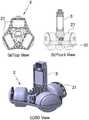
도 1은 본 발명의 바람직한 일 실시례에 따른 지능형 공구심부름 로봇을 도시하는 전체 구성도
도 2는 본 발명의 바람직한 일 실시례에 따른 지능형 공구심부름 로봇의 로봇팔 구성도
도 3은 본 발명의 바람직한 일 실시례에 따른 지능형 공구심부름 로봇의 자율주행수단의 구조도
도 4는 본 발명의 바람직한 일 실시례에 따른 지능형 공구심부름 로봇 시스템의 로봇제어기의 제어구조 블록도
도 5는 본 발명의 바람직한 일 실시례에 따른 지능형 공구심부름 로봇 시스템의 제어기 모듈을 도시하는 사진
도 6은 로봇에 설치되는 전방위 장애물회피 초음파센서 모듈의 사진
도 7은 본 발명과 연계되는 서랍 전면도(S1 ∼ S5)
도 8은 본 발명과 연계되는 공구에 적용되는 자성재질의 마크의 예시도BRIEF DESCRIPTION OF THE DRAWINGS Fig. 1 is an overall schematic view showing an intelligent tool eraser robot according to a preferred embodiment of the present invention
Fig. 2 is a block diagram of a robot arm of an intelligent tool eraser robot according to a preferred embodiment of the present invention
3 is a structural view of an autonomous traveling means of an intelligent tool eraser robot according to a preferred embodiment of the present invention
4 is a block diagram of a control structure of a robot controller of an intelligent tool eraser robot system according to a preferred embodiment of the present invention
Figure 5 is a photograph illustrating a controller module of an intelligent tool eraser robot system according to one preferred embodiment of the present invention.
6 is a photograph of the omni-directional obstacle avoidance ultrasonic sensor module installed in the robot
7 is a front view (S1 to S5) of a drawer associated with the present invention;
8 is an exemplary view of a mark of a magnetic material applied to a tool associated with the present invention
이하 본 발명에서 제공하는 지능형 공구심부름 로봇 시스템의 바람직한 일 실시례를 첨부 도면에 의거하여 상세히 설명한다.Hereinafter, a preferred embodiment of the intelligent tool eraser robot system provided in the present invention will be described in detail with reference to the accompanying drawings.
도 1은 본 발명의 바람직한 일 실시례에 따른 지능형 공구심부름 로봇을 도시하는 전체 구성도를 도시한 것이고, 도 2는 본 발명의 바람직한 일 실시례에 따른 지능형 공구심부름 로봇의 로봇팔 구성도, 도 3은 본 발명의 바람직한 일 실시례에 따른 지능형 공구심부름 로봇의 자율주행수단의 구조도를 각각 도시한 것이다.FIG. 1 is a block diagram showing an intelligent tool eraser robot according to a preferred embodiment of the present invention. FIG. 2 is a block diagram of a robot arm of an intelligent tool eraser robot according to a preferred embodiment of the present invention. 3 is a structural view of the autonomous traveling means of the intelligent tool eraser robot according to the preferred embodiment of the present invention.
본 발명에서 제공하는 지능형 공구심부름 로봇(1)은 도시된 바와 같이 하부에 사용지역에 바닥에 마킹되어 있는 은색 테이프(폭 10cm) 라인 추적을 통한 자율 주행이 가능한 자율주행수단(2)이 구비된다.As shown in the figure, the intelligent tool eraser robot 1 provided in the present invention is provided with autonomous travel means 2 capable of autonomous travel through line tracing of a silver tape (
자율주행수단(2)은 도 3에 도시된 바와 같이 하부에 3개의 바퀴(21)가 설치되어 있으며, 이들 3개의 바퀴(21)는 개별적인 구동 또는 동시 구동이 가능하고, 도시되지는 않았지만 360도 회전기능을 갖도록 구성하여 전방위로 방향 전환 및 이동이 가능하도록 구성한다. 그리고 자율주행수단(2)에는 다수의 근접센서(22)가 설치하여 이동 과정에서 주변에 장애물이 감지될 때 주행을 정지하거나 회피하는 기동을 통해서 은색 테이프 라인을 추적 하는 기능성을 함께 갖는다.As shown in FIG. 3, the autonomous traveling means 2 is provided with three
자율주행수단(2)의 상측으로는 바디부(3)가 결합 구성되며, 바디부(3)의 상측으로는 헤드부(4)가 설치되고, 바디부(3)의 좌우측으로는 각각 로봇팔(5)이 설치된다.A
바디부(3)의 전면에는 거리를 감지할 수 있는 초음파센서(6)가 상하측으로 부착되어 상기 자율주행수단(2)에 구비되는 근접센서(22)와 더불어 자율주행수단(2)의 주행이 원활히 이루어질 수 있도록 한다.An
상기 헤드부(4)에는 카메라(7)가 설치되어 있다. 카메라(7)는 공구의 형상과 그 공구의 모델 번호를 촬영하여 바디부(3)에 내장되어 있는 제어기(8)에 제공하는 기능성을 한다.A
바디부(3)의 양측으로 설치되는 로봇팔(5)은 사람의 팔과 같이 움직일 수 있는 어깨관절(51)과, 상부암(52)과, 팔꿈치관절(53)과, 하부암(54)과, 손목관절(55)과, 다관절로 구성되어 물건을 그리핑(Griping)할 수 있는 핸드어셈블리(56)로 구성되어 마치 사람이 팔을 움직이는 것과 유사한 동작이 구현될 수 있게 한다. 그리고 핸드어셈블리(56)에는 자성을 감지할 수 있는 자성감지센서가 구비되어 있다.The
이와 같은 구성의 로봇팔(5)은 구성 핸드어셈블리(56)를 통해서 서랍(10)을 열거나 테이블 위에 있는 물건을 그리핑할 수 있는 기능성을 제공한다.The
그리고 상기 바디부(3)의 내부에는 제어기(8)가 설치된다.A controller (8) is installed in the body part (3).
제어기(8)는 사용자의 문자/형상을 인식하여 저장하기 위하여 인식 후의 처리, 전처리 과정을 영상 인식 인터페이스 소프트웨어 키트와, 외부로부터 입력되는 입력 영상에 대하여 실제 영상인식의 구간을 계산하는 영상/형상 검출 소프트웨어 키트와, 상기 입력 영상에 대하여 실제 영상 인식 구간을 인식하는 영상 인식 소프트웨어 키트와, 인식된 영상 신호를 통해서 로봇의 핸드 및 동작모션, 그리고 자율주행을 제어하는 명령지시부(9)를 포함한다.In order to recognize and store the character / shape of the user, the
또한 제어기(8)는 일반 작업공정(제조산업)에서 필요한 공구, 즉 펜치, 망치, 드라이브, 렌치, 스패너, 톱, 드릴 등 50가지 공구의 형상을 기본모델형상으로 저장하고, 각 모델형상 저장 데이터 어드레스에 고유번호를 지정하여, 그 고유모델 번호를 버튼으로 누르면 로봇이 인지하여 지정 경로를 따라 이동하여 지정된 공구의 형상을 인지하여 찾아 가지고 올 수 있도록 한다.The
상기 명령지시부(9)는 바디부(3)의 외부에 노출식으로 구성되는 모니터 형식으로 구성될 수 있다.The
도 4는 본 발명의 바람직한 일 실시례에 따른 대화기능을 갖는 공구심부름 로봇의 로봇제어기의 제어구조 블록선도, 도 5는 본 발명의 바람직한 일 실시례에 따른 대화기능을 갖는 공구심부름 로봇 시스템의 제어기 모듈을 도시하는 사진이다.FIG. 4 is a block diagram showing a control structure of a robot controller of a tool eraser robot having an interactive function according to a preferred embodiment of the present invention; and FIG. 5 is a block diagram of a controller of a tool eraser robot system having an interactive function according to a preferred embodiment of the present invention. Fig.
도 4에 도시된 블록선도는 제어기(8)의 구조이며,


도 5에 도시된 바와 같이 제어기는 수신 모듈과, 송신 모듈과 메인 CPU로 이루어진다.As shown in FIG. 5, the controller includes a receiving module, a transmitting module, and a main CPU.
도 6은 로봇에 설치되는 전방위 장애물회피 초음파센서(6) 모듈의 사진이다.6 is a photograph of the omni-directional obstacle avoidance
도 7은 본 발명과 연계되는 서랍(10) 전면도(S1 ∼ S5)를 도시한 것이고, 도 8은 본 발명과 연계되는 공구에 적용되는 자성재질의 마크의 예시도를 도시한 것이다.Fig. 7 shows a front view (S1 to S5) of a
도시된 바에 의하면 서랍(10)의 각 단 (1단∼5단)의 지정 공구를 우선 배열한 후 그런 다음 제어기(8)에 그 위치를 저장한다. (ex. 1층 망치, 2층 펜치, 3층 스패너, 4층 렌치, 5층은 드릴, 톱, 서류종이 등)According to the drawings, the designated tool of each stage (first stage to fifth stage) of the
각 공구의 같은 종류의 모델이지만 치수가 다른 모델의 인식은 그 공구의 모델 번호를 부여한 후, 그 모델 번호를 문자인식을 통하여 인식하고 이동한다.Recognition of a model of the same kind of each tool, but of different dimensions, recognizes the model number of the tool by recognizing the model number through character recognition, and then moves it.
도시된 바에 의하면 서랍(10) 1단 속의 공구 1번(S1T1)에서 공구 10번(S1T10), 서랍(10) 2단 공구 1번(고유번호:S2T1)에서 공구 10번 (S2T10), 서랍(10) 3단 공구1번(고유번호:S3T1)에서 공구 10번(S3T10), 서랍(10) 4단 공구1번(고유번호:S4T1)에서 공구 10번(S4T10), 서랍(10) 5단 공구1번(고유번호:S5T1)에서 공구 10번(S5T10)까지의 서랍(10)속 공구 고유모델 번호가 표시되어 있다.The tool 10 (S2T10), the drawer (10), the drawer (10), and the drawer (10) in the first step S1T1 of the drawer (10) 10) The tool 10 (S4T10), the drawer 10 (10), the tool 10 (S3T10), the tool 10 (S3T1) The unique tool number in the drawer (10) from tool # 1 (S5T1) to tool # 10 (S5T10) is displayed.
상기 모든 공구에는 자성 재질로 된 ■마크를 부착해 두고, 로봇이 카메라(7)를 통하여 그 위치점을 인지한 후 그 무게중심에 기준하여 물건을 파지하도록 사전에 학습을 통해 파지가가 이루어질 수 있도록 제어기(8)에 파지방법을 저장해둔다.The mark of the magnetic material is attached to all of the tools, and the robot recognizes the position point thereof via the
이상과 같이 구성되는 본 발명의 지능형 공구 심부름 로봇의 경우 사용자가 바디부(3)에 노출되어 있는 명령지시부(9)를 통해서 공구의 고유번호 혹은 공구의 종류 등을 문자/형상으로 입력하면 제어기(8)에서 자율주행수단(2)에 이동명령을 내려 공구함으로 지능형 공구 심부름 로봇을 이동시키게 된다.In the case of the intelligent tool eraser robot of the present invention configured as described above, when the user inputs the unique number of the tool or the type of the tool in a character / shape through the
공구함 전방으로 이동한 상태에서 헤드부(4)에 설치되어 있는 카메라(7)를 통해서 제공되는 영상으로 공구함에 서랍(10) 단을 1차 확인 후 공구 번호에 해당하는 서랍(10)을 로봇팔(5)의 핸드어셈블리(56)로 파지하여 개방하고 내장되어 있는 공구를 카메라(7)로 확인 후 자성 재질로 된 ■마크 부분(무게 중심)을 그리핑한 상태에서 자율주행수단(2)을 이용하여 최초의 위치로 복귀하여 사용자에게 해당 공구를 전달하게 되는 것이다.The
이상과 같이 본 발명은 대화기능을 갖는 공구심부름 로봇 시스템을 제공하는 것을 주요한 기술적 사상으로 하고 있으며, 도면을 참고하여 상술한 실시 예는 단지 하나의 실시 예에 불과하므로 본 발명의 진정한 범위는 특허청구범위에 의해 결정되어야 한다.
As described above, the present invention is based on the technical idea of providing a tool eraser robot system having an interactive function, and since the above-described embodiment is only one embodiment with reference to the drawings, It should be determined by the range.
1:지능형 공구심부름 로봇 2:자율주행수단
21:바퀴 22:근접센서
3:바디부 4:헤드부
5:로봇팔 51:어깨관절
52:상부암 53:팔꿈치관절
54:하부암 55:손목관절
56:핸드어셈블리 6:초음파센서
7:카메라 8:제어기
9:명령지시부 10:서랍1: Intelligent tool errand robot 2: Self-propelled vehicle
21: Wheel 22: Proximity sensor
3: Body part 4: Head part
5: Robot arm 51: shoulder joint
52: upper arm 53: elbow joint
54: lower arm 55: wrist joint
56: Hand assembly 6: Ultrasonic sensor
7: camera 8: controller
9: command instruction section 10: drawer
Claims (4)
Translated fromKorean자율주행수단(2)의 상측으로 결합되며 전면으로 거리를 강지하는 초음파센서(6)가 부착된 바디부(3)와;
바디부(3)의 상측으로 설치되며 카메라(7)가 마련된 헤드부(4)와;
바디부(3)의 좌우측으로 설치되며 어깨관절(51)과, 상부암(52)과, 팔꿈치관절(53)과, 하부암(54)과, 손목관절(55)과, 다관절로 이루어진 핸드어셈블리(56)로 구성되어 마치 사람의 팔과 유사한 동작이 구현되어 공구함의 서랍(10)을 개방하고 공구함에 수납된 공구를 그리핑(Griping)하는 로봇팔(5)과;
상기 바디부(3)에 내장 설치되어 자율주행수단(2)과, 초음파센서(6), 카메라(7), 로봇팔(5)의 작동을 제어하는 제어기(8)를 포함하는 것을 특징으로 하는 지능형 공구심부름 로봇.
An autonomous travel means (2) provided with a plurality of proximity sensors (22) so as to allow autonomous travel through line tracking marked on the floor in the use area;
A body part 3 attached to the upper side of the autonomous traveling means 2 and attached with an ultrasonic sensor 6 for increasing the distance to the front side;
A head part 4 provided above the body part 3 and provided with a camera 7;
A shoulder joint 51, an upper arm 52, an elbow joint 53, a lower arm 54, a wrist joint 55, and a hand made of multiple joints, which are provided at right and left sides of the body part 3, A robot arm 5 composed of an assembly 56 and implemented as an operation similar to a human's arm to open the drawer 10 of the tool box and grip the tool housed in the tool box;
And a controller 8 installed in the body part 3 to control the operation of the autonomous traveling means 2 and the ultrasonic sensor 6, the camera 7 and the robot arm 5 Intelligent tool errand robot.
상기 제어기(8)는 사용자의 문자/형상을 인식하여 저장하기 위하여 인식 후의 처리, 전처리 과정을 영상 인식 인터페이스 소프트웨어 키트와, 외부로부터 입력되는 입력 영상에 대하여 실제 영상인식의 구간을 계산하는 영상/형상 검출 소프트웨어 키트와, 상기 입력 영상에 대하여 실제 영상 인식 구간을 인식하는 영상 인식 소프트웨어 키트와, 인식된 영상 신호를 통해서 로봇의 핸드 및 동작모션, 그리고 자율주행을 제어하는 명령지시부(9)를 포함하도록 구성한 것을 특징으로 하는 지능형 공구심부름 로봇.
The method of claim 1,
In order to recognize and store the character / shape of the user, the controller 8 performs an after-recognition process and a preprocessing process in an image recognition interface software kit and an image / shape A detection software kit, an image recognition software kit for recognizing an actual image recognition interval with respect to the input image, and a command instruction unit 9 for controlling the hand, motion motion, and autonomous travel of the robot through the recognized image signal Wherein the robot is a robot.
상기 제어기(8)는 일반 작업공정(제조산업)에서 필요한 공구, 즉 펜치, 망치, 드라이브, 렌치, 스패너, 톱, 드릴과 같은 50가지 공구의 형상을 기본모델형상으로 저장하고, 각 모델형상 저장 데이터 어드레스에 고유번호를 지정하여, 그 고유모델 번호를 버튼으로 누르면 로봇이 인지하여 지정 경로를 따라 이동하여 지정된 공구의 형상을 인지하여 찾아 가지고 올 수 있도록 한 것을 특징으로 하는 지능형 공구심부름 로봇.
The method of claim 1,
The controller 8 stores the shapes of 50 tools such as a pliers, a hammer, a drive, a wrench, a saw, and a drill in a basic model shape in a general work process (manufacturing industry) Wherein the robot is recognized and moved along a designated path by designating a unique number to a data address and pushing the inherent model number by a button so as to recognize and retrieve the shape of the designated tool.
상기 공구함의 서랍(10)과, 이들에 수납된 공구에는 자성 재질로 된 ■마크가 마련되며, 자성 재질로 된 ■마크는 무게중심에 위치되도록 한 것을 특징으로 하는 지능형 공구심부름 로봇.The method of claim 1,
Characterized in that the drawer (10) of the tool box and the tool housed therein are provided with a mark made of a magnetic material and the mark made of a magnetic material is positioned at the center of gravity.
Priority Applications (1)
| Application Number | Priority Date | Filing Date | Title |
|---|---|---|---|
| KR1020150044149AKR20160116445A (en) | 2015-03-30 | 2015-03-30 | Intelligent tools errands robot |
Applications Claiming Priority (1)
| Application Number | Priority Date | Filing Date | Title |
|---|---|---|---|
| KR1020150044149AKR20160116445A (en) | 2015-03-30 | 2015-03-30 | Intelligent tools errands robot |
Publications (1)
| Publication Number | Publication Date |
|---|---|
| KR20160116445Atrue KR20160116445A (en) | 2016-10-10 |
Family
ID=57146035
Family Applications (1)
| Application Number | Title | Priority Date | Filing Date |
|---|---|---|---|
| KR1020150044149ACeasedKR20160116445A (en) | 2015-03-30 | 2015-03-30 | Intelligent tools errands robot |
Country Status (1)
| Country | Link |
|---|---|
| KR (1) | KR20160116445A (en) |
Cited By (4)
| Publication number | Priority date | Publication date | Assignee | Title |
|---|---|---|---|---|
| CN107088880A (en)* | 2017-05-12 | 2017-08-25 | 江苏信息职业技术学院 | A kind of robot arm |
| CN110270993A (en)* | 2019-07-29 | 2019-09-24 | 永嘉县信达智能设备制造有限公司 | Robot shoulder structure |
| CN111958585A (en)* | 2020-06-24 | 2020-11-20 | 宁波薄言信息技术有限公司 | Intelligent disinfection robot |
| WO2021174850A1 (en)* | 2020-03-04 | 2021-09-10 | 河南理工大学 | Roadway roof-falling hazard automatic detection device |
Citations (1)
| Publication number | Priority date | Publication date | Assignee | Title |
|---|---|---|---|---|
| KR20080083746A (en) | 2007-03-13 | 2008-09-19 | 주식회사 유진로봇 | Ergonomic robot capable of delivering objects and messages through location recognition |
- 2015
- 2015-03-30KRKR1020150044149Apatent/KR20160116445A/ennot_activeCeased
Patent Citations (1)
| Publication number | Priority date | Publication date | Assignee | Title |
|---|---|---|---|---|
| KR20080083746A (en) | 2007-03-13 | 2008-09-19 | 주식회사 유진로봇 | Ergonomic robot capable of delivering objects and messages through location recognition |
Cited By (4)
| Publication number | Priority date | Publication date | Assignee | Title |
|---|---|---|---|---|
| CN107088880A (en)* | 2017-05-12 | 2017-08-25 | 江苏信息职业技术学院 | A kind of robot arm |
| CN110270993A (en)* | 2019-07-29 | 2019-09-24 | 永嘉县信达智能设备制造有限公司 | Robot shoulder structure |
| WO2021174850A1 (en)* | 2020-03-04 | 2021-09-10 | 河南理工大学 | Roadway roof-falling hazard automatic detection device |
| CN111958585A (en)* | 2020-06-24 | 2020-11-20 | 宁波薄言信息技术有限公司 | Intelligent disinfection robot |
Similar Documents
| Publication | Publication Date | Title |
|---|---|---|
| CN114728417B (en) | Method and apparatus for autonomous object learning by remote operator triggered robots | |
| CN111055281B (en) | A ROS-based autonomous mobile grasping system and method | |
| CN114102585B (en) | Article grabbing planning method and system | |
| CN205219101U (en) | Service robot of family | |
| Fang et al. | A novel augmented reality-based interface for robot path planning | |
| Chen et al. | Industrial robot control with object recognition based on deep learning | |
| Miljković et al. | New hybrid vision-based control approach for automated guided vehicles | |
| US20190321977A1 (en) | Architecture and methods for robotic mobile manipluation system | |
| CN110900575B (en) | A parallel intelligent robot with automatic guidance function and guidance method thereof | |
| US12059814B2 (en) | Object-based robot control | |
| CN106514667A (en) | Human-computer cooperation system based on Kinect skeletal tracking and uncalibrated visual servo | |
| KR20160116445A (en) | Intelligent tools errands robot | |
| CN107160403A (en) | A kind of intelligent robot system with multi-functional human-machine interface module | |
| CN111823277A (en) | An object grasping platform and method based on machine vision | |
| EP4095486A1 (en) | Systems and methods for navigating a robot using semantic mapping | |
| CN114888768A (en) | Mobile duplex robot cooperative grabbing system and method based on multi-sensor fusion | |
| CN114299039A (en) | Robot and collision detection device and method thereof | |
| CN110914021A (en) | Operating device with an operating device for carrying out at least one work step, and method and computer program | |
| KR102408327B1 (en) | AI-based Autonomous Driving Robot System That Supports Gesture Recognition For Autonomous Driving Sales | |
| CN116460846A (en) | Mechanical arm control method, device, equipment and storage medium | |
| CN116175582A (en) | A kind of intelligent manipulator control system and control method based on machine vision | |
| Hentout et al. | A telerobotic human/robot interface for mobile manipulators: A study of human operator performance | |
| Sim et al. | Development of an autonomous mobile manipulator for pick and place operation using 3d point cloud | |
| CN117798925A (en) | A mobile robot intelligent control method | |
| US20240375280A1 (en) | Method of manipulating a construction object, construction robot system, and computer program product |
Legal Events
| Date | Code | Title | Description |
|---|---|---|---|
| PA0109 | Patent application | Patent event code:PA01091R01D Comment text:Patent Application Patent event date:20150330 | |
| PA0201 | Request for examination | ||
| PG1501 | Laying open of application | ||
| E902 | Notification of reason for refusal | ||
| PE0902 | Notice of grounds for rejection | Comment text:Notification of reason for refusal Patent event date:20161013 Patent event code:PE09021S01D | |
| E601 | Decision to refuse application | ||
| PE0601 | Decision on rejection of patent | Patent event date:20170103 Comment text:Decision to Refuse Application Patent event code:PE06012S01D Patent event date:20161013 Comment text:Notification of reason for refusal Patent event code:PE06011S01I |