KR20160114978A - Apparatus and System for beam forming of array antenna - Google Patents
Apparatus and System for beam forming of array antennaDownload PDFInfo
- Publication number
- KR20160114978A KR20160114978AKR1020150041555AKR20150041555AKR20160114978AKR 20160114978 AKR20160114978 AKR 20160114978AKR 1020150041555 AKR1020150041555 AKR 1020150041555AKR 20150041555 AKR20150041555 AKR 20150041555AKR 20160114978 AKR20160114978 AKR 20160114978A
- Authority
- KR
- South Korea
- Prior art keywords
- beams
- base station
- unit
- mobile station
- present
- Prior art date
- Legal status (The legal status is an assumption and is not a legal conclusion. Google has not performed a legal analysis and makes no representation as to the accuracy of the status listed.)
- Withdrawn
Links
- 230000007613environmental effectEffects0.000claimsabstractdescription3
- 238000004891communicationMethods0.000description8
- 238000010586diagramMethods0.000description6
- 239000000470constituentSubstances0.000description5
- 238000010295mobile communicationMethods0.000description5
- 230000008859changeEffects0.000description2
- 230000001133accelerationEffects0.000description1
- 230000002238attenuated effectEffects0.000description1
- 230000008901benefitEffects0.000description1
- 230000005540biological transmissionEffects0.000description1
- 238000005259measurementMethods0.000description1
- 230000007246mechanismEffects0.000description1
- 238000000034methodMethods0.000description1
- 238000012986modificationMethods0.000description1
- 230000004048modificationEffects0.000description1
- 230000004044responseEffects0.000description1
Images


Classifications
- H—ELECTRICITY
- H04—ELECTRIC COMMUNICATION TECHNIQUE
- H04B—TRANSMISSION
- H04B7/00—Radio transmission systems, i.e. using radiation field
- H04B7/02—Diversity systems; Multi-antenna system, i.e. transmission or reception using multiple antennas
- H04B7/04—Diversity systems; Multi-antenna system, i.e. transmission or reception using multiple antennas using two or more spaced independent antennas
- H04B7/06—Diversity systems; Multi-antenna system, i.e. transmission or reception using multiple antennas using two or more spaced independent antennas at the transmitting station
- H04B7/0613—Diversity systems; Multi-antenna system, i.e. transmission or reception using multiple antennas using two or more spaced independent antennas at the transmitting station using simultaneous transmission
- H04B7/0615—Diversity systems; Multi-antenna system, i.e. transmission or reception using multiple antennas using two or more spaced independent antennas at the transmitting station using simultaneous transmission of weighted versions of same signal
- H04B7/0617—Diversity systems; Multi-antenna system, i.e. transmission or reception using multiple antennas using two or more spaced independent antennas at the transmitting station using simultaneous transmission of weighted versions of same signal for beam forming
- H—ELECTRICITY
- H04—ELECTRIC COMMUNICATION TECHNIQUE
- H04B—TRANSMISSION
- H04B7/00—Radio transmission systems, i.e. using radiation field
- H04B7/02—Diversity systems; Multi-antenna system, i.e. transmission or reception using multiple antennas
- H04B7/04—Diversity systems; Multi-antenna system, i.e. transmission or reception using multiple antennas using two or more spaced independent antennas
- H04B7/0408—Diversity systems; Multi-antenna system, i.e. transmission or reception using multiple antennas using two or more spaced independent antennas using two or more beams, i.e. beam diversity
- H—ELECTRICITY
- H04—ELECTRIC COMMUNICATION TECHNIQUE
- H04B—TRANSMISSION
- H04B7/00—Radio transmission systems, i.e. using radiation field
- H04B7/02—Diversity systems; Multi-antenna system, i.e. transmission or reception using multiple antennas
- H04B7/04—Diversity systems; Multi-antenna system, i.e. transmission or reception using multiple antennas using two or more spaced independent antennas
- H04B7/08—Diversity systems; Multi-antenna system, i.e. transmission or reception using multiple antennas using two or more spaced independent antennas at the receiving station
- H04B7/0891—Space-time diversity
- H04B7/0897—Space-time diversity using beamforming per multi-path, e.g. to cope with different directions of arrival [DOA] at different multi-paths
Landscapes
- Engineering & Computer Science (AREA)
- Computer Networks & Wireless Communication (AREA)
- Signal Processing (AREA)
- Radio Transmission System (AREA)
- Mobile Radio Communication Systems (AREA)
Abstract
Translated fromKorean
Description
Translated fromKorean본 발명은 고지향성 어레이 안테나의 빔 포밍 장치 및 시스템에 관한 것이다.The present invention relates to a beamforming apparatus and system for a high directivity array antenna.
차세대(5G) 이동통신을 위하여는 기존대비 1000배의 데이터 트래픽 용량이 필요하다고 한다. 하지만, 송신기에서 송신된 전파는 수신기에 이르기까지 자유공간 손실, 강우, 대기, 건물 및 지형 등 다양한 요인으로 인해 감쇄가 된다.For the next generation (5G) mobile communication, it needs 1000 times data traffic capacity compared to the existing one. However, the radio waves transmitted from the transmitter are attenuated due to various factors such as free space loss, rainfall, atmosphere, building and terrain until reaching the receiver.
이를 보상하기 위하여 안테나 이득이 높은 고지향성 안테나를 사용하여 경로 손실을 줄일 수 있다. 고지향성 안테나는 혼 안테나와 다수의 어레이 안테나 등이 있으며, 안테나 빔의 방향 전환을 위하여는 혼안테나인 경우는 물리적으로 방향을 틀어주어야 하나, 어레이(array) 안테나인 경우는 어레이를 구성하는 안테나 요소(element)의 가중치(weight)만을 조절하여 전기적으로 빔의 방향을 조정할 수 있다.To compensate for this, the path loss can be reduced by using a highly directional antenna with high antenna gain. In order to change the direction of the antenna beam, the horn antenna must be physically turned. In the case of an array antenna, however, the antenna element the direction of the beam can be electrically adjusted by adjusting only the weight of the element.
마이크로파보다 높은 주파수대역의 전파는 스캐터(scatter)의 개수가 제한적으로 모델되어 채널이 희소성(sparsity)의 특성을 나타내며, LoS (line-of-sight)와 NLoS (non-line-of-sight) 구별 없이 모두 스파스(sparse) 한 분포를 보여준다.Propagation in a frequency band higher than that of a microwave is limited by the number of scattering channels, so that the channel exhibits sparsity characteristics, and a line-of-sight (LoS) and a non-line-of-sight (NLoS) All show sparse distribution without distinction.
따라서, 송수신 안테나 간의 빔의 얼라인(align)이 잘못되면 수신전력이 없게 되어 통신 링크를 설정할 수 없게 된다. 특히, 이동통신환경에서는 단말과 주변환경이 지속적으로 변화하는데, 이에 따른 적절한 빔 형성을 수행하지 못하면, 설정된 통신 링크도 끊어지는 상황이 발생할 수 있다.Therefore, if the beams are misaligned between the transmitting and receiving antennas, there is no reception power and communication link can not be established. Particularly, in a mobile communication environment, when the terminal and the surrounding environment are continuously changed, if the proper beam forming is not performed, the established communication link may be disconnected.
본 발명의 목적은, 고주파수 대역의 이동통신 시스템에서 고지향성 어레이 안테나에 대한 빔의 방향을 정확히 추정하고 얼라인(align) 하여 빔을 형성하도록 하는 고지향성 어레이 안테나의 빔 포밍 장치 및 시스템을 제공함에 있다.An object of the present invention is to provide a beam forming apparatus and a system of a highly directional array antenna for precisely estimating and aligning a beam direction to a high directivity array antenna in a mobile communication system of a high frequency band to form a beam have.
본 발명의 기술적 과제들은 이상에서 언급한 기술적 과제들로 제한되지 않으며, 언급되지 않은 또 다른 기술적 과제들은 아래의 기재들로부터 당업자에게 명확하게 이해될 수 있을 것이다.The technical problems of the present invention are not limited to the above-mentioned technical problems, and other technical problems which are not mentioned can be understood by those skilled in the art from the following description.
상기의 목적을 달성하기 위한 본 발명에 따른 장치는, 무선 전파 특성 및 환경 파라미터를 이용해 이동국(Mobile Station, MS)의 빔(beam) 개수를 설정하는 빔 개수 설정부, 빔 개수 설정부에 의해 설정된 빔의 개수에 따라 각 안테나 소자의 가중치를 조절하여 안테나 패턴을 결정하고, 결정된 안테나 패턴에 따라 빔을 생성(generation)하는 빔 생성부, 빔 생성부에 의해 생성된 빔을 수평 방향 및 수직 방향 중 적어도 하나의 방향으로 회전(rotation)시키는 빔 회전부, 상기 빔 회전부에 의해 빔이 회전하는 동안 기지국(Base Station, BS)에서 송신된 빔의 방향과 빔의 개수를 탐색하는 밤 탐색부, 및 상기 빔 탐색부에 의해 탐색된 빔의 방향과 빔의 개수에 따라 빔 포밍을 수행하는 빔 포밍부를 포함하는 것을 특징으로 한다.According to an aspect of the present invention, there is provided an apparatus including: a beam number setting unit configured to set a beam number of a mobile station (MS) using radio wave propagation characteristics and environment parameters; A beam generator for generating an antenna pattern according to the determined antenna pattern by adjusting the weights of the antenna elements according to the number of beams and for generating a beam according to the determined antenna pattern; A night search section for searching for a direction and a number of beams transmitted from a base station (BS) while the beam is rotated by the beam rotating section, And a beam forming unit for performing beam forming according to the direction of the beam and the number of beams detected by the searching unit.
본 발명에 따르면, 고주파수 대역의 고지향성 안테나를 사용하는 이동통신 시스템에서 고지향성 어레이 안테나에 대한 빔의 방향을 정확히 추정하여 align 함으로써 통신 전파 채널이 스파스(sparse) 한 경우에도 통신 링크를 강인하게 설정하고 안정적으로 유지할 수 있는 이점이 있다.According to the present invention, in a mobile communication system using a high-directional antenna with a high frequency band, the direction of the beam to the high-directional array antenna is accurately estimated and aligned so that the communication link is robust even when the communication propagation channel is sparse There is an advantage that it can be set and stably maintained.
도 1은 본 발명에 따른 고지향성 어레이 안테나의 빔 포밍 장치의 구성을 도시한 도면이다.
도 2는 본 발명에 따른 고지향성 어레이 안테나의 빔 포밍 장치의 빔 개수 설정 동작을 설명하는데 참조되는 실시예를 도시한 도면이다.
도 3은 본 발명에 따른 고지향성 어레이 안테나의 빔 포밍 장치의 가중치 설정 동작을 설명하는데 참조되는 실시예를 도시한 도면이다.
도 4 및 도 5는 본 발명에 따른 고지향성 어레이 안테나의 빔 포밍 장치에 의해 생성된 안테나 패턴의 실시예를 도시한 도면이다.
도 6은 본 발명에 따른 고지향성 어레이 안테나의 빔 포밍 장치의 빔 방향성을 조절하는 동작의 실시예를 도시한 도면이다.
도 7은 본 발명에 따른 고지향성 어레이 안테나의 빔 포밍 시스템의 구성을 도시한 도면이다.
도 8은 본 발명에 따른 고지향성 어레이 안테나의 빔 포밍 시스템에서 빔 포밍을 수행하는 동작의 흐름을 도시한 도면이다.
도 9은 본 발명에 따른 고지향성 어레이 안테나의 빔 포밍 시스템에서 기지국의 안테나 패턴에 대한 실시예를 도시한 도면이다.
도 10 내지 도 12는 본 발명에 따른 고지향성 어레이 안테나의 빔 포밍 시스템에서 기지국의 빔 포밍 동작을 설명하는데 참조되는 실시예를 도시한 도면이다.1 is a diagram showing a configuration of a beam forming apparatus for a high directivity array antenna according to the present invention.
2 is a diagram showing an embodiment to be referred to in describing the beam number setting operation of the beam forming apparatus of the high directivity array antenna according to the present invention.
3 is a view illustrating an embodiment to be referred to in describing a weight setting operation of the beam forming apparatus of the high directivity array antenna according to the present invention.
4 and 5 are views showing an embodiment of the antenna pattern generated by the beam forming apparatus of the high directivity array antenna according to the present invention.
6 is a view showing an example of an operation for adjusting the beam directionality of the beam forming apparatus of the high directivity array antenna according to the present invention.
7 is a diagram showing a configuration of a beam forming system of a highly directional array antenna according to the present invention.
FIG. 8 is a flowchart illustrating an operation of performing beamforming in a beamforming system of a high directivity array antenna according to the present invention.
9 is a diagram illustrating an antenna pattern of a base station in a beamforming system of a high directivity array antenna according to the present invention.
FIGS. 10 to 12 are views illustrating an embodiment to be referred to in describing a beamforming operation of a base station in a beamforming system of a high directivity array antenna according to the present invention.
이하, 본 발명의 일부 실시예들을 예시적인 도면을 통해 상세하게 설명한다. 각 도면의 구성요소들에 참조부호를 부가함에 있어서, 동일한 구성요소들에 대해서는 비록 다른 도면상에 표시되더라도 가능한 한 동일한 부호를 가지도록 하고 있음에 유의해야 한다. 또한, 본 발명의 실시예를 설명함에 있어, 관련된 공지 구성 또는 기능에 대한 구체적인 설명이 본 발명의 실시예에 대한 이해를 방해한다고 판단되는 경우에는 그 상세한 설명은 생략한다.Hereinafter, some embodiments of the present invention will be described in detail with reference to exemplary drawings. It should be noted that, in adding reference numerals to the constituent elements of the drawings, the same constituent elements are denoted by the same reference numerals whenever possible, even if they are shown in different drawings. In the following description of the embodiments of the present invention, a detailed description of known functions and configurations incorporated herein will be omitted when it may make the difference that the embodiments of the present invention are not conclusive.
본 발명의 실시예의 구성 요소를 설명하는 데 있어서, 제 1, 제 2, A, B, (a), (b) 등의 용어를 사용할 수 있다. 이러한 용어는 그 구성 요소를 다른 구성 요소와 구별하기 위한 것일 뿐, 그 용어에 의해 해당 구성 요소의 본질이나 차례 또는 순서 등이 한정되지 않는다. 또한, 다르게 정의되지 않는 한, 기술적이거나 과학적인 용어를 포함해서 여기서 사용되는 모든 용어들은 본 발명이 속하는 기술 분야에서 통상의 지식을 가진 자에 의해 일반적으로 이해되는 것과 동일한 의미를 가진다. 일반적으로 사용되는 사전에 정의되어 있는 것과 같은 용어들은 관련 기술의 문맥상 가지는 의미와 일치하는 의미를 가진 것으로 해석되어야 하며, 본 출원에서 명백하게 정의하지 않는 한, 이상적이거나 과도하게 형식적인 의미로 해석되지 않는다.
In describing the components of the embodiment of the present invention, terms such as first, second, A, B, (a), and (b) may be used. These terms are intended to distinguish the constituent elements from other constituent elements, and the terms do not limit the nature, order or order of the constituent elements. Also, unless otherwise defined, all terms used herein, including technical or scientific terms, have the same meaning as commonly understood by one of ordinary skill in the art to which this invention belongs. Terms such as those defined in commonly used dictionaries should be interpreted as having a meaning consistent with the meaning in the context of the relevant art and are to be interpreted in an ideal or overly formal sense unless explicitly defined in the present application Do not.
도 1은 본 발명에 따른 빔 포밍 장치의 구성을 설명하는데 참조되는 도이다.BRIEF DESCRIPTION OF DRAWINGS FIG. 1 is a diagram referred to explain a configuration of a beam forming apparatus according to the present invention; FIG.
도 1을 참조하면, 본 발명에 따른 빔 포밍 장치는 빔 개수 설정부(110), 빔 생성부(120), 빔 회전부(130), 빔 탐색부(140) 및 빔 포밍부(150)를 포함할 수 있다.1, a beam forming apparatus according to the present invention includes a beam
빔 개수 설정부(110)는 이동국(Mobile Station, MS)의 빔(beam) 개수를 설정한다. 여기서, 이동국의 빔 개수 설정은 전파신호로부터 delay, angular, K-factor 등의 정보를 획득하여 활용한다. 이때, 빔 개수 설정부(110)는 무선 전파 측정(Radio propagation measurements) 데이터 및 스마트 단말의 GPS, 가속 센서, 자이로 등의 환경 파라미터(Environmental parameter)를 이용해 현 단말의 주변 환경을 파악하여 주변환경의 주요 전파 메커니즘에 따른 빔의 개수를 설정하도록 한다.The beam
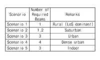
일 예로, 빔 개수 설정부(110)는 주변환경을 지방(rural), 교외(suburban), 도심지(urban), 고밀도 도심지(dense urban), 실내(indoor) 등으로 분류하고, 각 주변환경에 따라 필요한 방향성 레벨(directivity level)에 따라 빔의 개수를 설정할 수 있다.For example, the beam
이에 대한 실시예는 도 2와 같이 나타낼 수 있다.An embodiment of this can be represented as shown in FIG.
즉, 도 2의 시나리오(Scenario) 1과 같이, 지방(rural)에서 요구되는 방향성 이득이 'High' 이므로, 이에 따라 빔의 개수는 1로 설정할 수 있다. 또한, 도 2의 시나리오(Scenario) 2과 같이, 교외(suburban)에서 요구되는 방향성 이득이 'High' 이므로, 이에 따라 빔의 개수는 1 내지 2로 설정할 수 있다.That is, as in
또한, 도 2의 시나리오(Scenario) 3과 같이, 도심지(urban)에서 요구되는 방향성 이득이 'Medium' 이므로, 이에 따라 빔의 개수는 3으로 설정할 수 있다. 또한, 도 2의 시나리오(Scenario) 4과 같이, 고밀도 도심지(dense urban)에서 요구되는 방향성 이득이 'Low' 이므로, 이에 따라 빔의 개수는 4로 설정할 수 있다.Also, as in
또한, 도 2의 시나리오(Scenario) 5과 같이, 실내(indoor)에서 요구되는 방향성 이득이 'Low' 이므로, 이에 따라 빔의 개수는 3으로 설정할 수 있다. 여기서, 시나리오 5의 경우 요구되는 방향성 이득이 고밀도 도심지(dense urban)와 같은 'Low' 이긴 하나, 실내인 점을 감안하여 고밀도 도심지(dense urban) 보다 빔의 개수를 적게 설정할 수 있다.Also, as in
물론, 빔의 개수를 설정하는 실시예는 어느 하나에 한정되는 것은 아니며, 실시 형태에 따라 다양하게 적용 가능함은 당연한 것이다.Of course, the embodiment for setting the number of beams is not limited to any one, and it is obvious that various embodiments are applicable.
빔 생성부(120)는 빔 개수 설정부(110)에 의해 설정된 빔의 개수에 해당하는 빔을 생성(generation)하도록 한다. 이때, 빔 생성부(120)는 배열(array) 안테나 패턴을 조절하여 MS beam generation을 수행하도록 한다. 어레이 안테나의 안테나 패턴을 조절하는 실시예는 도 3과 같이 나타낼 수 있다.The
빔 생성부(120)는 도 3에 도시된 바와 같이, 어레이 안테나의 안테나 소자에 대해 가중치(weight)를 조절할 수 있다. 일 예로서, 빔 생성부(120)는 각 안테나 소자의 가중치 w1, w2, w3, w4, … wK를 각각 조절함으로써 안테나 패턴을 조절할 수 있다.The
이때, 생성할 수 있는 빔의 개수(M)와 안테나의 개수(N)는 'M ≤ N - 1'을 만족하는 것으로 한다. 다만, 실시 형태에 따라 안테나 개수에 따른 빔의 개수는 달라질 수도 있음은 당연한 것이다.At this time, it is assumed that the number of beams M to be generated and the number N of antennas satisfy 'M? N - 1'. However, it is a matter of course that the number of beams according to the number of antennas may be varied according to the embodiment.
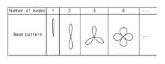
빔 생성부(120)에 의해 생성된 빔은 그 개수에 따라 다양한 빔 패턴을 구현할 수 있다. 빔 개수에 따른 빔 패턴의 실시예는 도 4와 같이 나타낼 수 있다.The beams generated by the
도 4를 참조하면, 빔 생성부(120)는 빔의 개수가 한 개인 경우 도면부호 411와 같이 하나의 방향성을 갖는 형태의 빔 패턴을 생성할 수 있다. 또한, 빔 생성부(120)는 빔의 개수가 두 개인 경우 도면부호 412와 같이 두 개의 방향성을 갖는 형태의 빔 패턴을 생성할 수 있다.Referring to FIG. 4, if the number of beams is one, the
또한, 빔 생성부(120)는 빔의 개수가 세 개인 경우 도면부호 413과 같이 세 개의 방향성을 갖는 형태의 빔 패턴을 생성할 수 있다. 또한, 빔 생성부(120)는 빔의 개수가 네 개인 경우 도면부호 414와 같이 네 개의 방향성을 갖는 형태의 빔 패턴을 생성할 수 있다.Also, the
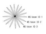
이와 같은 방식으로, 빔 생성부(120)는 빔의 개수가 K개인 경우 K개의 방향성을 갖는 빔 패턴을 생성할 수 있으며, 이때 생성된 각각의 빔은 도 5에 도시된 바와 같이 빔 ID가 부여될 수 있다.In this manner, when the number of beams is K, the
빔 회전부(130)는 어레이 안테나에 대한 가중치는 복소수로 크기 성분과 위상(phase) 성분을 갖는데, 가중치의 복소수 위상 성분을 조정함으로써 빔 생성부(120)에 의해 생성된 빔을 회전(rotation)시킬 수 있다. 이때, 빔 회전부(130)는 빔을 수평 방향 및/또는 수직 방향으로 회전시킬 수 있다. 여기서, 빔 탐색부(140)는 빔 회전부(130)에 의해 빔이 회전하는 동안 기지국(Base Station, BS)에서 송신된 빔의 방향과 빔의 개수를 탐색(search)할 수 있다.The
빔 탐색 동작은 링크 셋업을 목표로 한다. 다라서, 빔 회전부(130)는 다중 안테나의 빔을 샤프(sharp)하게 만드는 것보다 링크가 성립할 정도의 방향성(directivity)을 설정한 후에 빔을 회전시키고, 이때 빔 탐색부(140)가 기지국의 빔을 탐색하도록 한다.The beam search operation is aimed at link setup. Therefore, the
여기서, 링크 마진이 충분하지 않으면 이동국의 빔을 아무리 회전시키더라도 기지국의 빔이 탐색되지 않을 수 있다. 만일, 빔이 회전하는 동안 빔 탐색부(140)에 의해 기지국의 빔이 탐색되지 않으면, 어레이 안테나의 이득을 높이기 위하여 어레이 안테나의 빔의 개수를 줄여 방향성(directivity)을 높이도록 한다.Here, if the link margin is insufficient, the beam of the base station may not be searched even if the beam of the mobile station is rotated. If the
다시 말해, 빔 생성부(120)는 빔의 개수 M을 M-1로 조정하여 빔을 생성하고, 이후 빔 회전부(130)에서 M-1개의 빔을 회전시키는 상태에서 빔 탐색부(140)가 기지국의 빔을 탐색하도록 한다. 만일, 이 경우에도 기지국의 빔이 탐색되지 않으면, M을 M-2, M-3,.. 으로 조정하며 기지국의 빔을 탐색할 수 있다.In other words, the
이동통신 환경에서는 단말 환경과 주변환경이 시시각각으로 변화하기 때문에 빔 탐색부(140)는 단말의 리소스가 가능한대로 빔 탐색을 수행하여 빔 포밍에 대한 정보로 활용하도록 한다. 일 예로, 빔 탐색부(140)는 여분의 RF나, DTX (Discontinuous Transmission) 구간, DRX (Discontinuous Reception) 구간 등과 같이 패킷이 송수신되고 있지 않은 리소스를 활용하여 빔을 탐색할 수도 있다.In the mobile communication environment, since the terminal environment and the surrounding environment change instantaneously, the
만일, 빔 탐색부(140)에 의해 기지국의 빔이 탐색되면, 빔 포밍부(150)는 도 6과 같이 기지국의 빔의 방향과 이동국의 빔의 방향이 서로 나란하게 되도록 정비(align)하고 빔 포밍(beam forming)을 수행하도록 한다.
If the
도 7은 본 발명에 따른 빔 포밍 장치가 적용된 무선 통신 시스템을 도시한 도면이다. 도 7에서는 기지국과 이동국 간의 빔 포밍 동작에 대해 설명하고자 한다.FIG. 7 is a diagram illustrating a wireless communication system to which a beam forming apparatus according to the present invention is applied. 7, a beam forming operation between a base station and a mobile station will be described.
우선, 무선 통신 시스템의 빔 포밍은 기지국(200)의 빔 포밍이 먼저 수행된 후에 이동국(100)의 빔 포밍이 수행된다.First, the beamforming of the
기지국(200)은 다수의 빔 신호에 ID를 부여하여 하향링크를 통해 이동국(100)으로 방송하고, 이때 이동국(100)은 기지국(200)으로부터 수신한 빔 신호의 특징값을 측정하여 후보 빔(candidate beam)을 선정할 수 있다. 여기서, 이동국(100)은 후보 빔에 해당하는 빔의 개수 및 ID를 기지국(200)으로 전송하고, 기지국(200)은 이동국(100)으로부터 수신한 후보 빔의 정보에 근거하여 빔 포밍을 수행하도록 한다.The
이동국(100)은 기지국(200)의 빔 포밍이 완료되면, 기지국(200)의 빔을 수신하는 빔을 탐색하여 빔 포밍을 수행하도록 한다.When the beamforming of the
이에, 기지국(200)과 이동국(100)의 빔 포밍 동작에 대한 구체적인 설명은 도 8의 실시예를 참조하여 더욱 상세히 설명하도록 한다.A detailed description of the beamforming operation of the
도 8을 참조하면, 기지국(200)은 송신단(201)에서 하향링크를 통해 다수의 빔 신호를 방송한다(S110). 여기서, 기지국(200)은 기지국(200)의 빔 포밍을 위해 기지국(200)에서 사용 가능함 빔의 개수에 맞추어 빔을 생성한다.Referring to FIG. 8, the
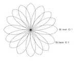
이때, 기지국(200)에 의한 빔 패턴은 도 9와 같이 나타낼 수 있다. 도 9에서와 같이, 기지국(200)은 빔의 순서에 따라 부여된 빔의 ID를 각 빔의 방향으로 송신하도록 한다.At this time, the beam pattern by the
이동국(100)은 수신단(105)에서 방송한 빔 신호를 수신할 수 있다. 이때, 이동국(100)은 기지국(200)으로부터 수신한 빔 신호들의 방향을 추정하여 해당 빔의 ID를 추정할 수 있다.The
이동국(100)에서 기지국(200)의 빔 신호에 대한 ID를 추정하는 실시예는 도 10을 참조하도록 한다.An embodiment for estimating the ID of the beam signal of the
도 10을 참조하면, 기지국(200)은 우선 기지국(200)으로부터 수신된 빔의 방향을 추정하는 알고리즘, 예를 들어, DOA(direction of arrival) 추정 알고리즘을 이용하여 빔의 방향을 1차로 추정한다. 이때, 기지국(200)은 수신된 빔 신호에서 1차 추정된 방향 성분을 제거하고 2차로 빔의 방향을 추정할 수 있다.10, the
이는, 고주파수 대역의 고지향성 안테나의 전파특성인 희소성(sparsity)을 이용하여 빔의 방향을 추정하는 것이다. 이 경우, 빔을 순차적으로 제거시킴으로써 빔 전력이 작은 성분의 빔 방향을 추정하는 경우에 빔 전력이 큰 성분의 영향을 최소화할 수 있다.This is to estimate the direction of the beam using the sparsity, which is the propagation characteristic of the high directional antenna in the high frequency band. In this case, by sequentially removing the beams, it is possible to minimize the influence of the component having a large beam power when estimating the beam direction of the component having a small beam power.
또한, 이동국(100)은 기지국(200)으로부터 수신된 다수의 빔 신호에 대한 특징값을 측정하고(S120), 후보 빔(candidate beam)을 선정할 수 있다. 이때, 이동국(100)은 기준 신호보다 신호 레벨이 큰 빔을 후보 빔으로 설정할 수 있다.In addition, the
일 예로서, 도 11에 도시된 바와 같이, 이동국(100)이 signal path 1 및 signal path 2를 통해 신호를 수신하는 경우, A 영역에서는 signal path 1만이 최저 신호 레벨(Minimum signal level) 이상이 되기 때문에 signal path 1의 신호를 후보 빔으로 설정할 수 있다.11, when the
B 영역에서는 signal path 1 및 signal path 2가 모두 최저 신호 레벨 이상이 되기 때문에 이동국(100)은 signal path 1 및 signal path 2 중 어느 하나의 신호를 후보 빔으로 설정하거나 두 신호 모두 후보 빔으로 설정할 수 있다.Since the
한편, C 영역에서는 signal path 2만이 최저 신호 레벨 이상이 되기 때문에 signal path 2의 신호를 후보 빔으로 설정할 수 있다.On the other hand, in the C region, signal
여기서, 이동국(100)은 통신 링크의 성립(link establishment)을 위하여 주변 환경(예를 들어, 도심, 부도심, 시골 등)에 따라 후보 빔의 개수를 설정하도록 한다(S130).Here, the
여기서, 주변 환경에 따라 후보 빔의 개수를 설정하는 실시예는 도 12를 참조하도록 한다. 즉, 도 12의 시나리오(Scenario) 1과 같이, 이동국(100)은 지방(rural)의 경우 기지국(200)에서 요구되는 빔의 개수를 1로 설정할 수 있으며, 시나리오(Scenario) 2와 같이 교외(suburban)의 경우에는 기지국(200)에서 요구되는 빔의 개수를 1 내지 2로 설정할 수 있다.Here, an example of setting the number of candidate beams according to the surrounding environment will be described with reference to FIG. That is, as in the
또한, 이동국(100)은 도 12의 시나리오(Scenario) 3과 같이 도심지(urban)인 경우 또는 시나리오(Scenario) 5과 같이 실내(indoor)인 경우 기지국(200)에서 요구되는 빔의 개수를 3으로 설정할 수 있으며, 시나리오(Scenario) 4와 같이 고밀도 도심지(dense urban)의 경우 기지국(200)에서 요구되는 빔의 개수를 4로 설정할 수 있다.In addition, when the
이때, 이동국(100)은 선정한 후보 빔에 대한 정보, 예를 들어, 후보 빔의 ID 정보를 상향링크를 통해 기지국(200)으로 전송한다(S140).At this time, the
기지국(200)의 수신단(205)에서는 이동국(100)으로부터 수신한 후보 빔에 대한 정보를 송신단(201)으로 전달한다. 이때, 수신단(205)은 기지국(200)의 피드팩 채널(feedback channel)을 통해 후보 빔에 대한 정보를 송신단(201)으로 전달하도록 한다.The receiving
기지국(200)은 이동국(100)으로부터 선정된 후보 빔의 정보에 근거하여 안테나의 빔 신호를 결정하고, 무선 자원을 스케줄링하여(S150), 해당 빔의 ID 정보를 이동국(100)으로 전송하도록 한다(S160).The
이때, 이동국(100)은 기지국(200)으로부터 전송되는 빔 신호에 근거하여 기지국(200)의 빔 포밍을 수행하도록 한다(S170). 여기서, 기지국(200)의 빔 포밍은 주로 통신 링크의 성립(link establishment)을 위하여 이동국(100)에서 주변 환경(도심, 부도심, 시골)에 따라 후보 빔(candidate beam)을 설정하도록 한다.At this time, the
한편, 이동국(100)의 빔 포밍은 BER, capacity과 같은 통신 성능의 향상을 위하여 단말에서 기지국(200)의 빔에 대한 주극(main lobe)과 이동국(100)의 빔에 대한 주극(main lobe)을 맞추는 미세조정(fine-tuning) 절차에 의해 수행될 수 있다. 이때 기지국(200)의 빔의 개수와 이동국(100)의 빔의 개수는 반드시 같을 필요는 없다.In order to improve communication performance such as BER and capacity, the beamforming of the
기지국(200)에서 빔 포밍을 수행하는 동안 기지국(200)은 계속해서 데이터를 전송할 수 있으며(S180), 이를 수신한 기지국(200)으로부터 응답 신호를 수신할 수 있다(S190).
The
이상의 설명은 본 발명의 기술 사상을 예시적으로 설명한 것에 불과한 것으로서, 본 발명이 속하는 기술 분야에서 통상의 지식을 가진 자라면 본 발명의 본질적인 특성에서 벗어나지 않는 범위에서 다양한 수정 및 변형이 가능할 것이다.The foregoing description is merely illustrative of the technical idea of the present invention, and various changes and modifications may be made by those skilled in the art without departing from the essential characteristics of the present invention.
따라서, 본 발명에 개시된 실시예들은 본 발명의 기술 사상을 한정하기 위한 것이 아니라 설명하기 위한 것이고, 이러한 실시예에 의하여 본 발명의 기술 사상의 범위가 한정되는 것은 아니다. 본 발명의 보호 범위는 아래의 청구범위에 의하여 해석되어야 하며, 그와 동등한 범위 내에 있는 모든 기술 사상은 본 발명의 권리범위에 포함되는 것으로 해석되어야 할 것이다.
Therefore, the embodiments disclosed in the present invention are intended to illustrate rather than limit the scope of the present invention, and the scope of the technical idea of the present invention is not limited by these embodiments. The scope of protection of the present invention should be construed according to the following claims, and all technical ideas within the scope of equivalents should be construed as falling within the scope of the present invention.
100: 이동국(MS)101: 송신단(TX)
105: 수신단(RX)10: 빔 개수 설정부
120: 빔 생성부130: 빔 회전부
140: 빔 탐색부150: 빔 포밍부
200: 기지국(BS)201: 송신단(TX)
205: 수신단(RX)100: mobile station (MS) 101: transmitting terminal (TX)
105: receiving end (RX) 10: beam number setting unit
120: beam generating unit 130: beam rotating unit
140: beam search unit 150: beamforming unit
200: base station (BS) 201: transmitting terminal (TX)
205: Receiver (RX)
Claims (1)
Translated fromKorean빔 개수 설정부에 의해 설정된 빔의 개수에 따라 각 안테나 소자의 가중치를 조절하여 안테나 패턴을 결정하고, 결정된 안테나 패턴에 따라 빔을 생성(generation)하는 빔 생성부;
빔 생성부에 의해 생성된 빔을 수평 방향 및 수직 방향 중 적어도 하나의 방향으로 회전(rotation)시키는 빔 회전부;
상기 빔 회전부에 의해 빔이 회전하는 동안 기지국(Base Station, BS)에서 송신된 빔의 방향과 빔의 개수를 탐색하는 빔 탐색부; 및
상기 빔 탐색부에 의해 탐색된 빔의 방향과 빔의 개수에 따라 빔 포밍을 수행하는 빔 포밍부
를 포함하는 것을 특징으로 하는 고지향성 어레이 안테나의 빔 포밍 장치.
A beam number setting unit for setting the number of beams of a mobile station (MS) using radio wave propagation characteristics and environmental parameters;
A beam generator for determining an antenna pattern by adjusting a weight value of each antenna element according to the number of beams set by the beam number setting unit, and generating a beam according to the determined antenna pattern;
A beam rotating unit for rotating the beam generated by the beam generating unit in at least one of a horizontal direction and a vertical direction;
A beam search unit for searching for a beam direction and a number of beams transmitted from a base station (BS) while the beam is rotated by the beam rotating unit; And
A beam forming unit for performing beam forming according to the direction of the beam detected by the beam searching unit and the number of beams,
Wherein the beam forming apparatus comprises:
Priority Applications (1)
| Application Number | Priority Date | Filing Date | Title |
|---|---|---|---|
| KR1020150041555AKR20160114978A (en) | 2015-03-25 | 2015-03-25 | Apparatus and System for beam forming of array antenna |
Applications Claiming Priority (1)
| Application Number | Priority Date | Filing Date | Title |
|---|---|---|---|
| KR1020150041555AKR20160114978A (en) | 2015-03-25 | 2015-03-25 | Apparatus and System for beam forming of array antenna |
Publications (1)
| Publication Number | Publication Date |
|---|---|
| KR20160114978Atrue KR20160114978A (en) | 2016-10-06 |
Family
ID=57164423
Family Applications (1)
| Application Number | Title | Priority Date | Filing Date |
|---|---|---|---|
| KR1020150041555AWithdrawnKR20160114978A (en) | 2015-03-25 | 2015-03-25 | Apparatus and System for beam forming of array antenna |
Country Status (1)
| Country | Link |
|---|---|
| KR (1) | KR20160114978A (en) |
Cited By (1)
| Publication number | Priority date | Publication date | Assignee | Title |
|---|---|---|---|---|
| KR101958163B1 (en)* | 2019-01-02 | 2019-07-04 | 알에프코어 주식회사 | Beamformer including signal detector for compensating weights, wireless transmitting and receiving device including beamformer, and operating method of wireless transmitting and receiving device |
Citations (1)
| Publication number | Priority date | Publication date | Assignee | Title |
|---|---|---|---|---|
| KR101613699B1 (en) | 2014-11-18 | 2016-04-19 | 에이스기계 주식회사 | Packing case |
- 2015
- 2015-03-25KRKR1020150041555Apatent/KR20160114978A/ennot_activeWithdrawn
Patent Citations (1)
| Publication number | Priority date | Publication date | Assignee | Title |
|---|---|---|---|---|
| KR101613699B1 (en) | 2014-11-18 | 2016-04-19 | 에이스기계 주식회사 | Packing case |
Cited By (2)
| Publication number | Priority date | Publication date | Assignee | Title |
|---|---|---|---|---|
| KR101958163B1 (en)* | 2019-01-02 | 2019-07-04 | 알에프코어 주식회사 | Beamformer including signal detector for compensating weights, wireless transmitting and receiving device including beamformer, and operating method of wireless transmitting and receiving device |
| US10784937B2 (en) | 2019-01-02 | 2020-09-22 | Rfcore Co., Ltd. | Beamformer including signal detector for compensating weights, wireless transmitting and receiving device including beamformer, and operating method of wireless transmitting and receiving device including beamformer |
Similar Documents
| Publication | Publication Date | Title |
|---|---|---|
| US20220166488A1 (en) | Method and apparatus for focused data communications | |
| CN112514281B (en) | Coexistence of radar detection and wireless communications | |
| Samimi et al. | 28 GHz millimeter-wave ultrawideband small-scale fading models in wireless channels | |
| CN115812159A (en) | Determining a location of a user equipment by using an adaptive phase change device | |
| US10405360B2 (en) | Method and equipment for establishing millimetre connection | |
| KR101822369B1 (en) | High-capacity hybrid terrestrial/satellite cellular radio communication system | |
| US11646783B2 (en) | Optimal beamforming in millimeter-wave cellular networks using a single composite random access preamble | |
| CN105580200B (en) | Apparatus and method for antenna alignment | |
| US9871570B1 (en) | Beam determining unit and beam-searching method for a wireless heterogeneous network | |
| GB2533966A (en) | System and method for selecting a beamforming configuration | |
| US10554277B2 (en) | Access node, user node and method for determining at least one beamforming parameter | |
| US10541462B2 (en) | Method for elimination of antenna angular orientation error in point-to-point communication system | |
| EP2897304A1 (en) | Methods of a first and a second radio access network node for configuring micro wave radio frequency transmission between a first highly directional antenna and a second highly directional antenna, first radio access network node and second radio access network node thereof | |
| CN105680918B (en) | Hierarchical beam forming method, base station and user equipment thereof | |
| US10644774B2 (en) | Wireless communication node adapted to radiate antenna beams of different types | |
| Peng et al. | Fast beam searching concept for indoor terahertz communications | |
| KR102281781B1 (en) | Apparatus and method for estimating angle of arrival of antenna signal | |
| US11218211B2 (en) | Iterative beam training method for accessing a mm-wave network | |
| Cheng et al. | 15 GHz propagation channel measurement at a university campus for the 5G spectrum | |
| WO2022187801A1 (en) | Phase vector training for adaptive phase-changing device-enabled communication | |
| US10320497B2 (en) | Control of directive antennas for wireless links | |
| US9847573B2 (en) | Method for antenna alignment in a non line-of-sight scenario | |
| KR20160114978A (en) | Apparatus and System for beam forming of array antenna | |
| EP4449622A1 (en) | Methods for supporting coexistence in the presence of non-terrestrial networks | |
| KR101994964B1 (en) | Beamforming antenna for Wi-Fi based indoor positioning |
Legal Events
| Date | Code | Title | Description |
|---|---|---|---|
| PA0109 | Patent application | Patent event code:PA01091R01D Comment text:Patent Application Patent event date:20150325 | |
| PG1501 | Laying open of application | ||
| PC1203 | Withdrawal of no request for examination |