KR20160111076A - Door hinge for wiring - Google Patents
Door hinge for wiringDownload PDFInfo
- Publication number
- KR20160111076A KR20160111076AKR1020150035738AKR20150035738AKR20160111076AKR 20160111076 AKR20160111076 AKR 20160111076AKR 1020150035738 AKR1020150035738 AKR 1020150035738AKR 20150035738 AKR20150035738 AKR 20150035738AKR 20160111076 AKR20160111076 AKR 20160111076A
- Authority
- KR
- South Korea
- Prior art keywords
- hinge
- hole
- space
- jaw
- wire
- Prior art date
- Legal status (The legal status is an assumption and is not a legal conclusion. Google has not performed a legal analysis and makes no representation as to the accuracy of the status listed.)
- Ceased
Links
- 230000008878couplingEffects0.000claimsabstractdescription28
- 238000010168coupling processMethods0.000claimsabstractdescription28
- 238000005859coupling reactionMethods0.000claimsabstractdescription28
- 238000009434installationMethods0.000claimsabstractdescription9
- 238000000034methodMethods0.000claims3
- 230000002093peripheral effectEffects0.000abstract1
- 238000003780insertionMethods0.000description2
- 239000002184metalSubstances0.000description2
- 238000012986modificationMethods0.000description2
- 230000004048modificationEffects0.000description2
- 238000009429electrical wiringMethods0.000description1
- 238000005516engineering processMethods0.000description1
- 230000037431insertionEffects0.000description1
- 238000012423maintenanceMethods0.000description1
- 239000000463materialSubstances0.000description1
- 230000000007visual effectEffects0.000description1
Images


Classifications
- E—FIXED CONSTRUCTIONS
- E05—LOCKS; KEYS; WINDOW OR DOOR FITTINGS; SAFES
- E05D—HINGES OR SUSPENSION DEVICES FOR DOORS, WINDOWS OR WINGS
- E05D11/00—Additional features or accessories of hinges
- E05D11/0081—Additional features or accessories of hinges for transmitting energy, e.g. electrical cable routing
- E—FIXED CONSTRUCTIONS
- E05—LOCKS; KEYS; WINDOW OR DOOR FITTINGS; SAFES
- E05D—HINGES OR SUSPENSION DEVICES FOR DOORS, WINDOWS OR WINGS
- E05D7/00—Hinges or pivots of special construction
- E05Y2201/602—
Landscapes
- Engineering & Computer Science (AREA)
- Mechanical Engineering (AREA)
- Hinges (AREA)
Abstract
Translated fromKoreanDescription
Translated fromKorean본 발명은 배관·배선이 가능한 여닫이 도어용 경첩에 관한 것으로서, 더욱 상세하게는 배관·배선이 가능한 여닫이 도어용 경첩에 관한 것이다.BACKGROUND OF THE
인테리어에 대한 소비자들의 욕구가 높아가면서 실내에 설치되는 문 내부에 조명등을 넣고 문짝의 겉면을 반투명하게 하여 문에서 은은한 조명 빛이 나오게 함으로써 다양한 시각적 효과를 내고자 하는 제품 개발이 이루어지고 있다.As consumers' desire for interior gets higher, the product is being developed to put various kinds of visual effects by putting the light inside the door installed in the room and translucent the outer surface of the door so that the soft light comes out from the door.
도 1에 도시된 것과 같은 기존 여닫이문에 부착하여 사용되는 경첩은 좌측 판(1)과 우측 판(2), 좌측 판과 우측 판을 연결하고 회전하게끔 하여 경첩의 기능을 하게 하는 핀(3)으로 구성되어 있다.A hinge used to attach to a conventional hinged door as shown in Fig. 1 includes a
그러나 이러한 기존의 여닫이문의 경첩을 사용하는 경우, 배관배선을 노출시키지 않고 문으로 전원 공급을 할 수가 없기 때문에 여닫이 도어에 배관배선에 따른 전선 등의 노출로 인한 미관 저해 없이 전원 공급을 할 수 있는 적절한 방법이 없어서 이러한 문제점을 해결할 수 있는 기술 개발이 요구되고 있는 실정이다.However, when such conventional door hinges are used, it is not possible to supply power to the door without exposing the piping wiring, so that the hinged door is suitably applicable to supply power without hindering the aesthetics due to the exposure of the wires etc. And there is a need for technology development that can solve these problems.
본 발명은 이러한 종래 기술의 문제점을 해결하기 위해서 안출된 것으로서, 본 발명은 여닫이 형식의 문에 배관 배선을 노출시키지 않고 문으로 전원 공급이 가능하도록 하는 배관·배선이 가능한 여닫이 도어용 경첩을 제공하는 데 그 목적이 있다.SUMMARY OF THE INVENTION The present invention is conceived to solve the problems of the prior art, and it is an object of the present invention to provide a hinges for a door of a hinged door which can be piped and wired so that power can be supplied to a door without exposing piping wiring to a door of a casement type It has its purpose.
이와 같은 상기의 목적을 달성하기 위한 본 발명에 따른 배선이 가능한 여닫이 도어용 경첩은 도어틀에 결합되어 고정되는 고정 플레이트와, 도어에 결합되어 상기 도어와 함께 회전되는 회전 플레이트와, 상기 고정 플레이트와 결합하고 상하 방향으로 뚫린 고정 축구멍이 형성되는 고정 결합단과, 상기 회전 플레이트와 결합하고 상하 방향으로 뚫린 회전 축구멍이 형성되며 상기 제1 결합단과 상하 방향으로 이어져서 상기 고정 축구멍 및 상기 회전 축구멍으로 이루어지며 상하로 길게 뻗은 하나의 영역인 힌지공간을 형성하는 회전 결합단과, 상기 힌지공간의 내주면 중 상기 힌지공간의 상단으로부터 일정 거리만큼 하방으로 떨어진 부위에 구비되는 상부 걸림턱과, 상기 힌지공간의 내주면 중 상기 힌지공간의 하단으로부터 일정 거리만큼 상방으로 떨어지고 상기 상부 걸림턱으로부터 일정 거리만큼 하방으로 떨어진 부위에 구비되는 하부 걸림턱과, 상기 힌지공간의 상단 구멍을 통해 들어와서 하단이 상기 상부 걸림턱에 닿을 때까지 삽입되어 일부는 상기 고정 축구멍 내부에 있고 나머지 일부는 상기 회전 축구멍 내부에 있도록 설치되는 상부 힌지축과, 상기 힌지공간의 하단 구멍을 통해 들어와서 상단이 상기 하부 걸림턱에 닿을 때까지 삽입되어 일부는 상기 고정 축구멍 내부에 있고 나머지 일부는 상기 회전 축구멍 내부에 있도록 설치되는 하부 힌지축과, 상기 상부 걸림턱과 상기 하부 걸림턱 사이 공간인 설치공간과 통하도록 상기 고정 결합단의 측면부에 형성되는 제1 전선 출입구멍과, 상기 설치공간과 통하도록 상기 회전 결합단의 측면부에 형성되는 제2 전선 출입구멍과, 상기 고정 플레이트의 배면에 상기 제1 전선 출입구멍과 통하도록 패여서 형성되는 제1 전선 인입홈 및 상기 회전 플레이트의 배면에 상기 제2 전선 출입구멍과 통하도록 패여서 형성되는 제2 전선 인입홈을 포함하여 구성된다.To achieve these and other advantages and in accordance with the purpose of the present invention, as embodied and broadly described herein, there is provided a door hinge for a door, comprising: a fixed plate coupled to and fixed to a door frame; a rotary plate coupled to the door, A fixed coupling step of engaging with the rotary plate and forming a fixed shaft hole formed in the upper and lower directions and a rotary shaft hole formed in the upper and lower directions by being engaged with the rotary plate and extending in the vertical direction with the first coupling step, An upper jaw jaw provided at a portion of the inner circumferential surface of the hinge space which is spaced apart from the upper end of the hinge space by a predetermined distance; The upper surface of the inner circumferential surface of the space is spaced a predetermined distance from the lower end of the hinge space A lower jaw provided at a position where the lower jaw is spaced apart from the upper jaw by a predetermined distance, a lower jaw provided at an upper end of the upper jaw, And the other part is inserted into the rotary shaft hole and inserted through the lower end hole of the hinge space until the upper end touches the lower stopping jaw, A first wire entry hole formed in a side surface of the fixed connection end to communicate with an installation space which is a space between the upper stopping jaw and the lower stopping jaw, A second wire entry / exit hole formed in a side portion of the rotary coupling end to communicate with the installation space, And a second wire inlet groove formed on the rear surface of the plate so as to communicate with the first wire outlet hole and a second wire inlet groove formed on the back surface of the rotary plate so as to communicate with the second wire outlet hole, .
또한, 상기 제1 전선 인입홈을 덮어씌우도록 상기 제1 전선 인입홈에 탈부착이 가능하게 끼워지고 전선 출입구멍이 형성된 제1 커버 및 상기 제2 전선 인입홈을 덮어씌우도록 상기 제2 전선 인입홈에 탈부착이 가능하게 끼워지고 전선 출입구멍이 형성되는 제2 커버를 더 포함하여 구성되는 것이 바람직하다.The first wire inlet groove may be formed in the first wire inlet groove. The first wire inlet groove may include a first cover having a first wire entry opening and a second wire entry opening groove. And a second cover which is detachably fitted to the first cover and is formed with a wire entry / exit hole.
또한, 상기 제1 커버 및 상기 제2 커버는 고무를 재질로 하는 것이 바람직하다.It is preferable that the first cover and the second cover are made of rubber.
또한, 상기 고정 결합단 및 상기 회전 결합단 각각은 두 개씩이 상하 간격을 두고 요철을 이루도록 돌출되고, 상기 요철의 들어간 부분과 나온 부분이 서로 맞물리는 구조를 가지는 것이 바람직하다.Preferably, each of the fixed coupling end and the rotational coupling end is protruded so as to have irregularities with two vertically spaced apart portions, and the protruding and recessed portions and the protruding portions are engaged with each other.
이상에서와 같이, 본 발명에 의한 배관·배선이 가능한 여닫이 도어용 경첩에 의하면 경첩을 이용하여 여닫이 형식의 문에 배관 배선을 노출시키지 않고 문으로 전원 공급할 수 있고, 경첩의 회전축이 되는 부분에 공간을 만들어 전선을 배선하거나 관련부속을 위치시킴으로써 경첩이 작동하여도 전기배선을 안전하게 배관할 수 있다는 장점이 있다.As described above, according to the hinge for the door of the hinged door according to the present invention, it is possible to supply power to the door without exposing the hinged door to the hinged door by using the hinge, , The electric wire can be securely piped even if the hinge is operated by wiring or placing the related parts.
도 1은 종래 기술에 의한 여닫이 도어용 경첩을 나타낸 정면도.
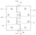
도 2는 본 발명에 의한 배관·배선이 가능한 여닫이 도어용 경첩을 나타낸 사시도.
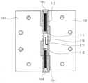
도 3은 본 발명에 의한 배관·배선이 가능한 여닫이 도어용 경첩을 나타낸 정면도.
도 4는 도 3의 단면도.
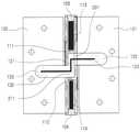
도 5는 본 발명에 의한 배관·배선이 가능한 여닫이 도어용 경첩을 나타낸 배면도.
도 6은 도 5의 단면도.
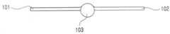
도 7은 본 발명에 의한 배관·배선이 가능한 여닫이 도어용 경첩을 나타낸 평면도.
도 8은 본 발명에 의한 배관·배선이 가능한 여닫이 도어용 경첩을 나타낸 평단면도.
도 9는 본 발명에 의한 배관·배선이 가능한 여닫이 도어용 경첩의 사용 상태도.1 is a front view showing a hinge for a hinged door according to the prior art.
BACKGROUND OF THE
3 is a front view showing a hinging for a door of a hinged door capable of piping and wiring according to the present invention.
Fig. 4 is a sectional view of Fig. 3; Fig.
5 is a rear view showing a hinging for a door of a door capable of piping and wiring according to the present invention.
Fig. 6 is a sectional view of Fig. 5; Fig.
7 is a plan view showing a hinging for a door of a hinged door capable of piping and wiring according to the present invention.
8 is a plan sectional view showing a hinge for a hinged door capable of piping and wiring according to the present invention.
FIG. 9 is a view showing a use state of a hinging for a door of a hinged door capable of piping and wiring according to the present invention. FIG.
이하, 본 발명의 구체적인 실시 예를 첨부된 도면을 참고하여 상세하게 설명한다.Hereinafter, specific embodiments of the present invention will be described in detail with reference to the accompanying drawings.
도 2는 본 발명에 의한 배관·배선이 가능한 여닫이 도어용 경첩을 나타낸 사시도이다.Fig. 2 is a perspective view showing a hinge for a door of a door capable of piping and wiring according to the present invention. Fig.
본 발명에 의한 배관·배선이 가능한 여닫이 도어용 경첩은 고정 플레이트(101), 회전 플레이트(102), 고정 결합단(200), 회전 결합단(210), 상부 걸림턱(111), 하부 걸림턱(112), 상부 힌지축(113), 하부 힌지축(114), 제1 커버(124) 및 제2 커버(125)를 포함하여 구성된다.The hinges for a door of a door capable of piping and wiring according to the present invention include a
고정 플레이트(101)는 도어틀에 결합되어 고정되는 금속제 판이고, 회전 플레이트(102)는 도어에 결합되어 힌지축(113,114)을 중심으로 도어와 함께 회전되는 금속제 판이다.The
고정 플레이트(101)의 우측 말단에는 상하로 간격을 두고 두 개의 직사각형 형태의 고정 결합단(200)이 올록볼록한 요철 형태를 이루도록 결합되고, 회전 플레이트(102)의 좌측 말단에는 상하로 간격을 두고 두 개의 직사각형 형태의 회전 결합단이 올록볼록한 요철 형태를 이루도록 결합되며, 고정 결합단(200)이 결합되어 볼록한 부분은 회전 결합단(210)들 사이의 오목한 부분에 삽입되고, 회전 결합단(210)이 결합되어 볼록한 부분은 고정 결합단(200)들 사이의 오목한 부분에 삽입되어 양쪽의 요철이 서로 맞물리는 구조를 이룬다.At the right end of the
고정 결합단(200)에는 수직 방향으로 관통하는 고정 축구멍이 형성되고, 회전 결합단(210)에는 수직 방향으로 관통하는 회전 축구멍이 형성된다.A fixed shaft hole is formed in the
두 개의 고정 축구멍과 두 개의 회전 축구멍이 서로 통하도록 수직 방향으로 일렬로 배치되어 수직 방향으로 길게 힌지공간(115)이 형성된다.The two fixed shaft holes and the two rotary shaft holes are arranged in a line in the vertical direction so as to communicate with each other so that the
힌지공간(115)의 내주면 중 힌지공간(115)의 상단으로부터 일정 거리만큼 하방으로 떨어진 부위에는 상부 걸림턱(111)이 내부로 돌출 형성되고, 힌지공간(115)의 내주면 중 상기 힌지공간(115)의 하단으로부터 일정 거리만큼 상방으로 떨어지고 상부 걸림턱(111)으로부터 일정 거리만큼 하방으로 떨어진 부위에는 하부 걸림턱(112)이 구비된다.An
상부 힌지축(113)은 상하 방향으로 길게 뻗은 원형 봉 형태의 부재로서 힌지공간(115)의 상단구멍에 끼워지는 상부 덮개(103)와 상부 걸림턱(111) 사이에 들어가서 설치되고, 하부 힌지축(114)은 상하 방향으로 길게 뻗은 원형 봉 형태의 부재로서 힌지공간(115)의 하단구멍에 끼워지는 하부 덮개(104)와 하부 걸림턱(112) 사이에 들어가서 설치된다.The
상부 힌지축(113)은 맨 윗쪽에 있는 회전 결합단(210) 전체에 의해 둘러싸이고 고정 결합단(200) 중 위쪽에 위치하는 고정 결합단(200)의 상부에 의해 둘러싸인다.The
하부 힌지축(114)은 맨 아래쪽에 있는 고정 결합단(200) 전체에 의해 둘러싸이고 회전 결합단(210) 중 아래쪽에 위치하는 고정 결합단(200)의 하부에 의해 둘러싸인다.The
본 명세서에서 힌지공간(115) 중에서 상부 걸림턱(111)과 하부 걸림턱(112) 사이 공간은 설치공간이라 칭하기로 하며, 도 6에 도시된 것과 같이 설치공간은 전선(121)이 통과하고 별도의 커넥터장치 등 관련부속이 설치되는 공간이다.In this specification, a space between the
제1 전선 출입구멍(201)은 설치공간과 통하도록 설치공간을 둘러싸는 고정 결합단(200)의 측면부에 형성되고, 제2 전선 출입구멍(211)은 설치공간과 통하도록 설치공간을 둘러싸는 회전 결합단(210)의 측면부에 형성된다.The first wire inlet /
제1 전선 인입홈(122)은 고정 플레이트(101)의 배면에 상기 제1 전선 출입구멍(201)과 통하도록 패여서 형성되고, 제2 전선 인입홈(132)은 회전 플레이트(102)의 배면에 상기 제1 전선 출입구멍(201)과 통하도록 패여서 형성된다.The first
제1 커버(124)는 제1 전선 인입홈(122)을 덮어씌우도록 제1 전선 인입홈(122)과 대응되는 형태 및 크기를 가진 부재로서 제1 전선 인입홈(122)에 탈부착이 가능하게 끼워지고 전선 출입구멍(123)이 형성된 것이며, 제2 커버(125)는 제2 전선 인입홈(132)을 덮어씌우도록 제2 전선 인입홈(132)과 대응되는 형태 및 크기를 가진 부재로서 제2 전선 인입홈(132)에 탈부착이 가능하게 끼워지고 전선 출입구멍(133)이 형성된 것이다. 제1 커버(124) 및 제2 커버(125)는 고무 소재로 이루어진다.The
제1 커버(124)와 제2 커버(125)를 장착함으로써 배선을 보호하고 유지 보수 시 경첩을 문과 문틀에서 분리 후 제1 커버(124)와 제2 커버(125)를 열고 작업할 수 있다. 제1 커버(124)와 제2 커버(125)에는 전선(121)이 나올 수 있는 구멍인 전선 출입구멍(123,133)이 타공되어 제1 커버(124)의 전선 출입구멍(123)으로 들어가서 제1 전선 인입홈(122)을 지나 설치공간을 지난 후 제2 전선 인입홈(132)을 지나서 제2 커버(125)의 전선 출입구멍(133)으로 빠져나옴으로써 문과 문틀 사이에 전기 배선을 할 수 있다.The
상부 힌지축(113)은 상부 걸림턱(111)에 걸려서 밑으로 내려오지 못하고 하부 힌지축(114)은 하부 걸림턱(112)에 의해 위로 올라오지 못하기 때문에 설치공간이 안전하게 확보된 상태로 있어서 경첩이 작동해도 전기배선을 안전하게 배관된 상태를 유지할 수 있다.The
이상의 설명에서와 같이 본 발명은 바람직한 구체적인 예들에 대해서만 기술하였으나, 상기의 구체적인 예들을 바탕으로 한 본 발명의 기술사상 범위 내에서의 다양한 변형 및 수정이 가능함은 당업자에게 있어서 명백한 것이며, 또한, 이러한 변형 및 수정이 첨부된 특허청구범위에 속함은 당연한 것이다.It will be apparent to those skilled in the art that various modifications and variations can be made in the present invention without departing from the spirit and scope of the invention as set forth in the accompanying drawings. And modifications are within the scope of the appended claims.
101: 고정 플레이트 102: 회전 플레이트
103: 상부 덮개 104: 하부 덮개
111: 상부 걸림턱 112: 하부 걸림턱
113: 상부 힌지축 114: 하부 힌지축
115: 힌지공간 121: 전선
122: 제1 전선 인입홈 132: 제2 전선 인입홈
124: 제1 커버 125: 제2 커버
123, 133: 전선 출입구멍 200: 고정 결합단
201: 제1 전선 출입구멍 210: 회전 결합단
211: 제2 전선 출입구멍101: stationary plate 102: rotating plate
103: upper cover 104: lower cover
111: upper jaw 112: lower jaw
113: upper hinge shaft 114: lower hinge shaft
115: hinge space 121: wire
122: first wire entry groove 132: second wire entry groove
124: first cover 125: second cover
123, 133: Wire entry hole 200: Fixed coupling end
201: first wire entry hole 210: rotation coupling end
211: second wire entry hole
Claims (4)
Translated fromKorean도어에 결합되어 상기 도어와 함께 회전되는 회전 플레이트;
상기 고정 플레이트와 결합하고 상하 방향으로 뚫린 고정 축구멍이 형성되는 고정 결합단;
상기 회전 플레이트와 결합하고 상하 방향으로 뚫린 회전 축구멍이 형성되며 상기 제1 결합단과 상하 방향으로 이어져서 상기 고정 축구멍 및 상기 회전 축구멍으로 이루어지며 상하로 길게 뻗은 하나의 영역인 힌지공간을 형성하는 회전 결합단;
상기 힌지공간의 내주면 중 상기 힌지공간의 상단으로부터 일정 거리만큼 하방으로 떨어진 부위에 구비되는 상부 걸림턱;
상기 힌지공간의 내주면 중 상기 힌지공간의 하단으로부터 일정 거리만큼 상방으로 떨어지고 상기 상부 걸림턱으로부터 일정 거리만큼 하방으로 떨어진 부위에 구비되는 하부 걸림턱;
상기 힌지공간의 상단 구멍을 통해 들어와서 하단이 상기 상부 걸림턱에 닿을 때까지 삽입되어 일부는 상기 고정 축구멍 내부에 있고 나머지 일부는 상기 회전 축구멍 내부에 있도록 설치되는 상부 힌지축;
상기 힌지공간의 하단 구멍을 통해 들어와서 상단이 상기 하부 걸림턱에 닿을 때까지 삽입되어 일부는 상기 고정 축구멍 내부에 있고 나머지 일부는 상기 회전 축구멍 내부에 있도록 설치되는 하부 힌지축;
상기 상부 걸림턱과 상기 하부 걸림턱 사이 공간인 설치공간과 통하도록 상기 고정 결합단의 측면부에 형성되는 제1 전선 출입구멍;
상기 설치공간과 통하도록 상기 회전 결합단의 측면부에 형성되는 제2 전선 출입구멍;
상기 고정 플레이트의 배면에 상기 제1 전선 출입구멍과 통하도록 패여서 형성되는 제1 전선 인입홈; 및
상기 회전 플레이트의 배면에 상기 제2 전선 출입구멍과 통하도록 패여서 형성되는 제2 전선 인입홈을 포함하여 구성되는 것을 특징으로 하는 배관·배선이 가능한 여닫이 도어용 경첩.A fixing plate coupled and fixed to the door frame;
A rotary plate coupled to the door and rotated together with the door;
A stationary engaging step of engaging with the stationary plate and forming a stationary shaft hole in a vertical direction;
A hinge space formed by the fixed shaft hole and the rotary shaft hole and extending upward and downward to form a hinge space, the hinge shaft being connected to the first coupling end in a vertical direction, A rotating coupling end;
An upper jaw provided at a portion of the inner circumferential surface of the hinge space which is spaced downward by a predetermined distance from an upper end of the hinge space;
A lower latching jaw provided at a portion of the inner circumferential surface of the hinge space that is spaced apart from the lower end of the hinge space by a predetermined distance and is spaced downward by a predetermined distance from the upper latching jaw;
An upper hinge shaft that is inserted through the upper hole of the hinge space and inserted until the lower end thereof reaches the upper engaging jaw, a part of the upper hinge shaft is located inside the fixed shaft hole,
A lower hinge shaft inserted through the lower end hole of the hinge space and inserted until the upper end thereof contacts the lower stopping jaw, a part of the lower hinge shaft is located inside the fixed shaft hole,
A first wire access hole formed in a side surface of the fixed connection end to communicate with an installation space which is a space between the upper stopping jaw and the lower stopping jaw;
A second wire access hole formed in a side surface portion of the rotary coupling end to communicate with the installation space;
A first wire entry groove formed on the back surface of the fixing plate so as to be pierced to communicate with the first wire entry / exit hole; And
And a second wire entry groove formed on a rear surface of the rotary plate so as to communicate with the second wire entry / exit hole.
상기 제1 전선 인입홈을 덮어씌우도록 상기 제1 전선 인입홈에 탈부착이 가능하게 끼워지고 전선 출입구멍이 형성된 제1 커버; 및
상기 제2 전선 인입홈을 덮어씌우도록 상기 제2 전선 인입홈에 탈부착이 가능하게 끼워지고 전선 출입구멍이 형성되는 제2 커버를 포함하여 구성되는 것을 특징으로 하는 배관·배선이 가능한 여닫이 도어용 경첩.The method according to claim 1,
A first cover which is detachably fitted in the first wire entry groove so as to cover the first wire entry groove and has a wire entry hole; And
And a second cover which is detachably fitted in the second wire lead-in groove so as to cover the second wire lead-in groove and in which a wire lead-in hole is formed. .
상기 제1 커버 및 상기 제2 커버는 고무를 재질로 하는 것을 특징으로 하는 배관·배선이 가능한 여닫이 도어용 경첩.3. The method of claim 2,
Wherein the first cover and the second cover are made of rubber.
상기 고정 결합단 및 상기 회전 결합단 각각은 두 개씩이 상하 간격을 두고 요철을 이루도록 돌출되고, 상기 요철의 들어간 부분과 나온 부분이 서로 맞물리는 구조를 가지는 것을 특징으로 하는 배관·배선이 가능한 여닫이 도어용 경첩.4. The method according to any one of claims 1 to 3,
Wherein each of the fixed connection end and the rotation connection end is protruded so as to have irregularities with two vertically spaced apart portions and the protruding and recessed portion and the protruding portion are engaged with each other. Hinges for use.
Priority Applications (1)
| Application Number | Priority Date | Filing Date | Title |
|---|---|---|---|
| KR1020150035738AKR20160111076A (en) | 2015-03-16 | 2015-03-16 | Door hinge for wiring |
Applications Claiming Priority (1)
| Application Number | Priority Date | Filing Date | Title |
|---|---|---|---|
| KR1020150035738AKR20160111076A (en) | 2015-03-16 | 2015-03-16 | Door hinge for wiring |
Publications (1)
| Publication Number | Publication Date |
|---|---|
| KR20160111076Atrue KR20160111076A (en) | 2016-09-26 |
Family
ID=57068358
Family Applications (1)
| Application Number | Title | Priority Date | Filing Date |
|---|---|---|---|
| KR1020150035738ACeasedKR20160111076A (en) | 2015-03-16 | 2015-03-16 | Door hinge for wiring |
Country Status (1)
| Country | Link |
|---|---|
| KR (1) | KR20160111076A (en) |
Cited By (4)
| Publication number | Priority date | Publication date | Assignee | Title |
|---|---|---|---|---|
| CN107355155A (en)* | 2017-09-05 | 2017-11-17 | 邹红 | Three-in-one intelligent door hinge |
| CN108150040A (en)* | 2018-02-08 | 2018-06-12 | 曹大双 | A kind of water flowing hinge |
| CN112943786A (en)* | 2019-12-11 | 2021-06-11 | 上海轲吉智能科技有限公司 | Hinge assembly |
| US20220065013A1 (en)* | 2018-12-21 | 2022-03-03 | Safran Electrical & Power | Door hinge for an electrical cabinet |
- 2015
- 2015-03-16KRKR1020150035738Apatent/KR20160111076A/ennot_activeCeased
Cited By (5)
| Publication number | Priority date | Publication date | Assignee | Title |
|---|---|---|---|---|
| CN107355155A (en)* | 2017-09-05 | 2017-11-17 | 邹红 | Three-in-one intelligent door hinge |
| CN108150040A (en)* | 2018-02-08 | 2018-06-12 | 曹大双 | A kind of water flowing hinge |
| US20220065013A1 (en)* | 2018-12-21 | 2022-03-03 | Safran Electrical & Power | Door hinge for an electrical cabinet |
| US11993966B2 (en)* | 2018-12-21 | 2024-05-28 | Safran Electrical & Power | Door hinge for an electrical cabinet |
| CN112943786A (en)* | 2019-12-11 | 2021-06-11 | 上海轲吉智能科技有限公司 | Hinge assembly |
Similar Documents
| Publication | Publication Date | Title |
|---|---|---|
| KR20160111076A (en) | Door hinge for wiring | |
| CA2688044C (en) | Pivoting while-in-use electrical box and cover | |
| CA2592830C (en) | Universal recessed while-in-use box and cover | |
| CN110042630B (en) | Door hinge and laundry treating device having the same | |
| US8791362B2 (en) | Shutter door assembly for an electrical panel | |
| US20100124849A1 (en) | Electrical Box | |
| BR102015020169B1 (en) | electric machine | |
| RU2401400C2 (en) | Hollow axle joint | |
| JP5886570B2 (en) | Outlet | |
| US20170224103A1 (en) | Desktop receptacle with hinged cover | |
| CA2968231A1 (en) | Watertight box and adapter | |
| CN112802724B (en) | Electric connection box | |
| KR102005774B1 (en) | The system box of a undergrounded type with a slide type cover | |
| RU2010116348A (en) | FLOOR ELECTRICAL DISTRIBUTION BOX INCLUDING CONNECTING MODULES FOR THE ADAPTATION OF ELECTRICAL, RADIOTELEPHONE AND INFORMATION AND MULTIMEDIA DEVICES OR OTHER OTHERS | |
| KR101096344B1 (en) | Wall buried safety outlet | |
| JP5513156B2 (en) | Heat source unit | |
| KR200476291Y1 (en) | Multi electric outlet for bathroom cabinet | |
| TWI428502B (en) | Hinge device | |
| CN214841270U (en) | An easy-to-repair electrical box body and an air conditioner outdoor unit | |
| JP2014009881A (en) | Mounting structure of wiring cover | |
| KR101028139B1 (en) | Electrical outlet box on the inside wall of the apartment | |
| KR200449265Y1 (en) | Electric control box | |
| ES2257174B1 (en) | PLUG BASE WITH SECURITY SHUTTER AND MULTIFUNCTIONAL FRAME. | |
| CN209568293U (en) | Harness fixtures for garment care equipment and garment care equipment | |
| KR20070065139A (en) | Structure for changing door opening and closing direction of drum washing machine |
Legal Events
| Date | Code | Title | Description |
|---|---|---|---|
| PA0109 | Patent application | Patent event code:PA01091R01D Comment text:Patent Application Patent event date:20150316 | |
| PA0201 | Request for examination | ||
| PE0902 | Notice of grounds for rejection | Comment text:Notification of reason for refusal Patent event date:20160316 Patent event code:PE09021S01D | |
| PG1501 | Laying open of application | ||
| E601 | Decision to refuse application | ||
| PE0601 | Decision on rejection of patent | Patent event date:20160927 Comment text:Decision to Refuse Application Patent event code:PE06012S01D Patent event date:20160316 Comment text:Notification of reason for refusal Patent event code:PE06011S01I |