KR20160110106A - Method of fusion-splicing optical fibers and fusion splicer - Google Patents
Method of fusion-splicing optical fibers and fusion splicerDownload PDFInfo
- Publication number
- KR20160110106A KR20160110106AKR1020160023606AKR20160023606AKR20160110106AKR 20160110106 AKR20160110106 AKR 20160110106AKR 1020160023606 AKR1020160023606 AKR 1020160023606AKR 20160023606 AKR20160023606 AKR 20160023606AKR 20160110106 AKR20160110106 AKR 20160110106A
- Authority
- KR
- South Korea
- Prior art keywords
- optical fiber
- pair
- movable stages
- fusion
- windshield cover
- Prior art date
- Legal status (The legal status is an assumption and is not a legal conclusion. Google has not performed a legal analysis and makes no representation as to the accuracy of the status listed.)
- Withdrawn
Links
- 239000013307optical fiberSubstances0.000titleclaimsabstractdescription99
- 238000007526fusion splicingMethods0.000titleclaimsabstractdescription39
- 238000000034methodMethods0.000titleclaimsabstractdescription19
- 230000004927fusionEffects0.000titleclaimsdescription18
- 238000012360testing methodMethods0.000claimsdescription10
- 230000002040relaxant effectEffects0.000abstract1
- 238000012545processingMethods0.000description5
- 238000013459approachMethods0.000description4
- 238000007499fusion processingMethods0.000description4
- 239000000463materialSubstances0.000description4
- 230000003014reinforcing effectEffects0.000description4
- 230000006835compressionEffects0.000description3
- 238000007906compressionMethods0.000description3
- 238000005452bendingMethods0.000description2
- 230000000903blocking effectEffects0.000description2
- 230000000052comparative effectEffects0.000description1
- 239000000470constituentSubstances0.000description1
- 238000010276constructionMethods0.000description1
- 238000011156evaluationMethods0.000description1
- 238000012986modificationMethods0.000description1
- 230000004048modificationEffects0.000description1
- 238000003825pressingMethods0.000description1
- 230000002787reinforcementEffects0.000description1
- 238000003466weldingMethods0.000description1
Images


Classifications
- G—PHYSICS
- G02—OPTICS
- G02B—OPTICAL ELEMENTS, SYSTEMS OR APPARATUS
- G02B6/00—Light guides; Structural details of arrangements comprising light guides and other optical elements, e.g. couplings
- G02B6/24—Coupling light guides
- G02B6/255—Splicing of light guides, e.g. by fusion or bonding
- G02B6/2551—Splicing of light guides, e.g. by fusion or bonding using thermal methods, e.g. fusion welding by arc discharge, laser beam, plasma torch
- G—PHYSICS
- G02—OPTICS
- G02B—OPTICAL ELEMENTS, SYSTEMS OR APPARATUS
- G02B6/00—Light guides; Structural details of arrangements comprising light guides and other optical elements, e.g. couplings
- G02B6/24—Coupling light guides
- G02B6/255—Splicing of light guides, e.g. by fusion or bonding
- G02B6/2553—Splicing machines, e.g. optical fibre fusion splicer
Landscapes
- Physics & Mathematics (AREA)
- Engineering & Computer Science (AREA)
- Plasma & Fusion (AREA)
- General Physics & Mathematics (AREA)
- Optics & Photonics (AREA)
- Mechanical Coupling Of Light Guides (AREA)
Abstract
Translated fromKoreanDescription
Translated fromKorean본 발명은 광파이버끼리를 융착 접속하는 융착 접속 방법 및 융착 접속 장치에 관한 것이다.FIELD OF THE INVENTION The present invention relates to a fusion splicing method and a fusion splicing device for splicing optical fibers together.
일본 특허 공개 제2003-167151호 공보는, 본체와, 본체 상에 배치된 1쌍의 방전 전극과, 본체 상의 스테이지에 장착되어 광파이버를 유지하는 홀더와, 방전 전극이나 스테이지를 개폐 자유롭게 덮는 방풍 커버를 구비한 광파이버의 융착 접속기를 개시하고 있다. 방풍 커버의 측면의 각각에는, 홀더에 광파이버를 도입하기 위한 도입구가 형성되고, 도입구의 상부를 막도록 폐색용 탄성체가 마련되어 있다. 한편, 본체 측에는, 방풍 커버를 닫은 상태에서 하우징에 마련된 폐색용 탄성체에 대응하는 개소에, 도입구의 하부를 막도록 폐색용 탄성체가 마련되어 있다. 그리고, 방풍 커버를 닫은 상태에서, 방풍 커버의 폐색용 탄성체와 하우징의 폐색용 탄성체의 사이에 광파이버가 끼워짐과 아울러, 도입구를 막도록 구성되어 있다.Japanese Patent Application Laid-Open No. 2003-167151 discloses a plasma display panel comprising a main body, a pair of discharge electrodes arranged on the main body, a holder mounted on the stage on the main body and holding the optical fiber, and a windshield cover covering the discharge electrode and the stage And a fusion splicer for the optical fiber. In each of the side surfaces of the windshield cover, an introduction port for introducing an optical fiber into the holder is formed, and an occlusion elastic body is provided so as to cover the upper portion of the introduction port. On the other hand, on the side of the main body, an occlusion elastic body is provided at a position corresponding to the occlusion elastic body provided in the housing in a state where the windshield cover is closed, so as to close the lower portion of the mouth. In the state that the windshield cover is closed, the optical fiber is sandwiched between the elastic body for covering the windshield cover and the elastic body for covering the housing, and the inlet port is closed.
본 발명은, 광파이버의 융착 접속 후에 방풍 커버를 열었을 때에, 광파이버의 융착 접속부가 단선되는 것을 방지 가능한 광파이버의 융착 접속 방법 및 융착 접속 장치를 제공하는 것을 목적으로 한다.An object of the present invention is to provide an optical fiber fusion splicing connection method and a fusion splicing splicing device which can prevent the fusion splicing portion of an optical fiber from being broken when the windshield cover is opened after fusion splicing of optical fibers.
본 발명의 광파이버의 융착 접속 방법은, 1쌍의 가동 스테이지 상에 각각 배치된 광파이버 유지부에 광파이버를 유지하고, 방풍 커버에 의해 광파이버 유지부를 덮는 스텝과, 1쌍의 가동 스테이지를 서로 접근시켜 광파이버의 단면(端面)을 맞대는 스텝과, 맞댄 광파이버끼리를 융착 접속하는 스텝과, 방풍 커버를 열기 전에, 광파이버 유지부와 방풍 커버의 광파이버와 접촉하는 부분의 사이에서, 광파이버에 부여되는 장력(張力)을 완화하는 스텝을 구비한다.A fusing and connecting method for an optical fiber according to the present invention includes steps of holding an optical fiber in an optical fiber holding portion disposed on a pair of movable stages and covering the optical fiber holding portion with a windshield cover, A step of fitting the optical fibers to each other by fusing together the end faces of the optical fiber holding portions and a portion of the windshield cover contacting the optical fibers before opening the windshield cover, ).
본 발명의 광파이버의 융착 접속 방법은, 1쌍의 가동 스테이지 상에 각각 배치된 광파이버 유지부에 광파이버를 유지하고, 방풍 커버에 의해 광파이버 유지부를 덮는 스텝과, 1쌍의 가동 스테이지를 서로 접근시켜 광파이버의 단면을 맞대는 스텝과, 맞댄 광파이버끼리를 융착 접속하는 스텝과, 방풍 커버를 열기 전에, 1쌍의 가동 스테이지를 서로 멀어지도록 이동시키는 스텝을 구비한다.A fusing and connecting method for an optical fiber according to the present invention includes steps of holding an optical fiber in an optical fiber holding portion disposed on a pair of movable stages and covering the optical fiber holding portion with a windshield cover, And a step of moving the pair of movable stages away from each other before opening the windshield cover.
1쌍의 가동 스테이지를 서로 멀어지도록 이동시키는 스텝 후에, 방풍 커버를 여는 스텝과, 방풍 커버를 연 후에, 1쌍의 가동 스테이지끼리가 더 멀어지도록 1쌍의 가동 스테이지를 이동시키고, 광파이버의 융착 접속부의 프루프 테스트(proof test)를 실시하는 스텝을 더 구비하는 것이 바람직하다.A step of opening the windshield cover after the step of moving the pair of movable stages away from each other; and a step of moving the pair of movable stages so that the pair of movable stages are farther apart from each other after the windshield cover is opened, And performing a proof test of the test result.
본 발명의 광파이버의 융착 접속 장치는 본 발명의 광파이버의 융착 접속 방법에 의해 광파이버끼리를 융착 접속한다.The fusion splicing device of the optical fiber of the present invention fuses and connects the optical fibers by the fusion splicing method of the optical fiber of the present invention.
본 발명에 의하면, 광파이버의 융착 접속 후에 방풍 커버를 열었을 때에, 광파이버의 융착 접속부가 단선되는 것을 방지 가능한 광파이버의 융착 접속 방법 및 융착 접속 장치를 제공할 수 있다.According to the present invention, it is possible to provide a fusion splicing connection method of an optical fiber and a fusion splicing connection device that can prevent the fusion splicing portion of an optical fiber from being broken when the windshield cover is opened after fusion splicing of the optical fiber.
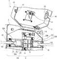
도 1은 본 발명에 따른 융착 접속 장치의 실시 형태에 있어서의 융착 처리부를, 방풍 커버를 연 상태에서 나타내는 사시도이다.
도 2의 (a), (b), (c) 각각은, 도 1의 융착 접속 장치가 포함하는 가동 스테이지를, 광파이버 홀더를 유지한 상태에서 나타내는 개략도로서, (a)는 스테이지 본체가 원점 위치에 있는 상태, (b)는 광파이버의 단면끼리를 맞댄 상태, (c)는 광파이버에 장력이 걸린 상태를 나타내고 있다.
도 3은 본 발명에 따른 광파이버의 융착 접속 방법의 실시 형태를 나타내는 흐름도이다.BRIEF DESCRIPTION OF THE DRAWINGS Fig. 1 is a perspective view showing a fusing treatment section in an embodiment of a fusing and connecting apparatus according to the present invention in a state where a windshield cover is opened. Fig.
2 (a), (b) and (c) are schematic views showing a movable stage included in the fusion splicing device of FIG. 1 in a state in which the optical fiber holder is held, (B) shows a state in which the end faces of the optical fibers come back to each other, and (c) shows a state in which tension is applied to the optical fiber.
3 is a flowchart showing an embodiment of a fusion splicing method of an optical fiber according to the present invention.
이하, 본 발명에 따른 광파이버의 융착 접속 방법 및 융착 접속 장치의 실시 형태의 예를, 도면을 참조하여 설명한다. 도면은, 설명을 목적으로 하며, 발명의 범위를 한정하고자 하는 것은 아니다. 도면에서, 설명의 중복을 피하기 위해, 동일한 부호는 동일 부분을 나타낸다. 도면 중의 치수의 비율은 반드시 정확하지 않다.BEST MODE FOR CARRYING OUT THE INVENTION Hereinafter, an embodiment of a fusion splicing method and a fusion splicing apparatus of an optical fiber according to the present invention will be described with reference to the drawings. The drawings are for illustrative purposes only and are not intended to limit the scope of the invention. In the drawings, the same reference numerals denote the same parts in order to avoid duplication of description. The ratio of dimensions in the figure is not necessarily correct.
일본 특허 공개 제2003-167151호 공보가 기재하고 있는 광파이버의 융착 접속기에서는, 방풍 커버를 닫은 상태에서 상하의 폐색용 탄성체의 사이에서 광파이버가 유지 고정되기 때문에, 광파이버가 그 축 방향을 따라 이동하는 것을 저해하는 부하가 광파이버에 걸려 있다. 예를 들면, 시중의 전주(電柱)로부터 가입자집까지를 접속하는 드롭 케이블(drop cable)이나, 구내(構內)나 가정 네트워크에 이용되는 인도어 케이블(indoor cable)과 같이 단면(斷面) 형상이 비(非)원형인 케이블, 바깥 직경이 굵은 케이블(예를 들면 바깥 직경 20㎜ 이상), 혹은 바깥 표면의 마찰이 큰 케이블의 경우는 특히 부하가 걸리기 쉽다. 그 때문에, 광파이버끼리의 융착 접속 처리가 완료된 후에, 방풍 커버를 열면, 광파이버에 걸려 있던 부하가 갑자기 해제되어, 광파이버가 그 축 방향으로 의도치 않게 이동하여, 광파이버끼리의 융착 접속부가 단선되어 버리는 경우가 있다. 본 발명은, 광파이버의 융착 접속 후에 방풍 커버를 열었을 때에, 광파이버의 융착 접속부가 단선되는 것을 방지 가능한 광파이버의 융착 접속 방법 및 융착 접속 장치를 제공하는 것을 목적으로 한다.In the optical fiber fusion splicer disclosed in Japanese Patent Application Laid-Open No. 2003-167151, since the optical fiber is held and fixed between the upper and lower elastic bodies in the closed state of the windshield cover, the optical fiber is prevented from moving along its axial direction The load on the optical fiber is caught by the optical fiber. For example, it is possible to use a drop cable for connecting the electric pole to a subscriber's house or an indoor cable used for a domestic network or a home network, In the case of this non-circular cable, a cable having a large outer diameter (for example, an outer diameter of 20 mm or more), or a cable having a large friction on the outer surface, Therefore, when the windshield cover is opened after the fusion splicing process between the optical fibers is completed, the load hanging on the optical fiber is suddenly released, the optical fiber unintentionally moves in the axial direction thereof, and the fusion splicing portion of the optical fibers is disconnected . An object of the present invention is to provide an optical fiber fusion splicing connection method and a fusion splicing splicing device which can prevent the fusion splicing portion of an optical fiber from being broken when the windshield cover is opened after fusion splicing of optical fibers.
도 1은 본 발명의 실시 형태에 따른 융착 접속 장치(1)에 있어서의 융착 처리부(3)를, 방풍 커버(4)를 연 상태에서 나타내는 사시도이다. 융착 접속 장치(1)는, 예를 들면 광파이버 설비의 공사가 행해지는 현지에서 광파이버끼리를 융착 접속하는 장치이다. 특히, 본 실시 형태는 드롭 케이블(100)에 내장되는 광파이버(110)끼리를 융착 접속하는 경우에 적합하다.1 is a perspective view showing a
융착 접속 장치(1)는 상자 모양의 하우징(2)을 구비하고 있다. 하우징(2)의 상부에는, 드롭 케이블(100)로부터 노출된 광파이버(110)끼리를 융착하기 위한 융착 처리부(3)가 마련되어 있다. 또, 융착 접속 장치(1)는 융착 처리부(3)로의 바람의 진입을 방지하기 위한 방풍 커버(4)를 구비하고 있다. 또한, 융착 접속 장치(1)는 하우징(2)의 내부에 배치된 카메라(도시 생략)에 의해 촬상된 광파이버(110)끼리의 융착 접속 상황을 표시하는 모니터(도시 생략)를 구비하고 있다. 작업자는 모니터에 표시된 광파이버(110)의 융착 개소의 영상을 보면서 모니터를 조작해서 융착 작업을 행할 수 있다.The fusion splicing device (1) has a box-shaped housing (2). At the upper portion of the housing 2, there is provided a
융착 처리부(3)는 1쌍의 방전 전극(10)과, 1쌍의 방전 전극(10) 사이에서 광파이버(110)의 접속 단면(端面)을 대향시켜 드롭 케이블(100)을 유지하는 1쌍의 가동 스테이지(20A, 20B)를 구비하고 있다. 1쌍의 가동 스테이지(20A, 20B) 상에는 드롭 케이블(100)을 유지 고정하는 홀더(30A, 30B)(광파이버 유지부의 일례)가 각각 마련되어 있다. 1쌍의 방전 전극(10) 및 가동 스테이지(20A, 20B)를 포함하는 융착 처리부(3)는 개폐 자유로운 방풍 커버(4)에 의해 덮을 수 있도록 구성되어 있다.The
1쌍의 방전 전극(10)은 각각 선단(先端)이 뾰족한 바늘 형상의 전극이며, 간격을 두고 서로 대향 배치된다. 광파이버(110)의 융착 접속시에는, 방전 전극(10) 사이에서 방전시키고, 방전열로 광파이버(110)의 단면(端面)을 용해하여 접속한다. 1쌍의 방전 전극(10)이 대향하는 위치를 방전부(15)라고 한다.The pair of
1쌍의 가동 스테이지(20A, 20B)는, 홀더(30A, 30B)를 거쳐서, 1쌍의 드롭 케이블(100)을 각각 유지한다. 이것에 의해, 1쌍의 방전 전극(10)의 대향 방향과 직교하는 방향으로 광파이버(110)의 단면끼리가 대향하여 배치된다. 1쌍의 가동 스테이지(20A, 20B)는, 광파이버(110)의 융착 접속시에, 양 광파이버(110)의 단면이 접근하도록 수평 방향으로 이동 가능하다. 1쌍의 가동 스테이지(20A, 20B)와 방전 전극(10)의 사이에는 V홈 지지부(60)가 형성되어 있다. V홈 지지부(60)의 표면에는 V홈이 형성되고, 당해 V홈에 홀더(30A, 30B)로부터 돌출된 광파이버(110)의 선단부가 배치된다.The pair of
홀더(30A, 30B)는 각각, 베이스부(31)와 뚜껑부(32)를 구비하고, 각 가동 스테이지(20A, 20B)에 착탈 가능하게 구성되어 있다. 홀더(30A, 30B)는 베이스부(31)와 뚜껑부(32)의 사이에 드롭 케이블(100)을 사이에 두고 유지 고정한다.Each of the
방풍 커버(4)는 융착 처리부(3)를 개폐 자유롭게 덮도록 하우징(2)에 연결되고 있다. 방풍 커버(4)의 이면측(융착 처리부(3)와 대향하는 측)에는, 방풍 커버(4)를 닫았을 때에, 드롭 케이블(100)을 V홈 지지부(60)로 누르는 클램프(41)가 마련되어 있다. 방풍 커버(4)의 양측면에는, 융착 처리부(3)로(즉 홀더(30A, 30B)의 각각으로) 드롭 케이블(100)을 도입하기 위한 도입구(42)가 형성되어 있다. 도입구(42)의 각각은 대략 직사각형 형상의 노치로 되어 있다. 방풍 커버(4)의 이면 측에는, 도입구(42)의 적어도 상부를 막도록 폐색용 탄성체(43)가 마련되어 있다. 폐색용 탄성체(43)는, 예를 들면 스펀지재나 고무재로 구성되어 있다.The windshield cover (4) is connected to the housing (2) so as to cover the fusion processing part (3) freely. A
한편, 하우징(2)에는, 방풍 커버(4)를 닫은 상태에서 폐색용 탄성체(43)에 대응하는 개소에, 도입구(42)의 하부를 막도록 폐색용 탄성체(50)가 마련되어 있다. 폐색용 탄성체(50)도, 예를 들면 스펀지재나 고무재로 구성되어 있다. 하우징(2)의 폐색용 탄성체(50)는, 방풍 커버(4)를 닫은 상태에서, 방풍 커버(4)의 폐색용 탄성체(43)과의 사이에 드롭 케이블(100)을 끼움과 아울러, 폐색용 탄성체(43)와 협동하여 도입구(42)를 막는다.On the other hand, the housing 2 is provided with an occlusion
드롭 케이블(100)이 하우징(2)의 폐색용 탄성체(50) 상에 배치된 상태에서 방풍 커버(4)를 닫으면, 폐색용 탄성체(43, 50)의 탄성력에 의해 드롭 케이블(100)을 누를 수 있다. 또한, 방풍 커버(4)를 닫는 것에 의해, 폐색용 탄성체(43)의 하면과 폐색용 탄성체(50)의 상면이 드롭 케이블(100)을 따르도록 변형되어, 도입구(42)와 드롭 케이블(100)의 간극이 폐색된다. 이것에 의해, 도입구(42)를 거친 융착 처리부(3)로의 바람의 진입이 방지된다.When the wind shield cover 4 is closed with the
도 2의 (a), (b), (c) 각각은 융착 접속 장치(1)가 포함하는 가동 스테이지(20A, 20B)를, 홀더(30A, 30B)를 각각 지지한 상태에서 나타내는 개략도이다. 1쌍의 가동 스테이지(20A, 20B)는 각각, 스테이지 본체(21)와, 피드(feed) 나사(25)와, 스프링(27)을 구비하고 있다.2 (a), 2 (b) and 2 (c) are schematic views showing the
스테이지 본체(21)는, 홀더(30A, 30B)가 그 상면에 설치되는 홀더 설치부(22)와, 홀더 설치부(22)의 앞쪽측 및 뒤쪽측의 측면으로부터 각각 아래쪽으로 돌출하는 앞벽부(23)와 뒷벽부(24)를 구비하고 있다. 도 2(a)에 나타내는 바와 같이, 광파이버(110)의 융착 접속 전에는, 1쌍의 가동 스테이지(20A, 20B)의 각 스테이지 본체(21)는 방전부(15)를 중심으로 하여 서로 이격된 원점 위치에 배치되어 있다.The stage
피드 나사(25)는, 스테이지 본체(21)의 아래쪽에 마련되어 있고, 홀더(30A, 30B)에 지지되는 드롭 케이블(100)의 축 방향으로 이동 가능하다. 피드 나사(25)는, 모터(도시 생략)에 의해 구동되고, 스테이지 본체(21)를 가압하고, 가동 스테이지(20A, 20B)를 원점 위치로부터 방전부(15)로 향해 이동(가압 이동)시킬 수 있다. 구체적으로는, 도 2(b)에 나타내는 바와 같이, 피드 나사(25)는, 스테이지 본체(21)의 앞벽부(23)를 방전부(15)와는 반대측으로부터 가압하여, 가동 스테이지(20A, 20B)를 방전부(15)로 향해 서로 접근하도록 전진시키고, 광파이버(110)의 단면끼리를 맞댄다.The
스프링(27)은, 피드 나사(25)에 의해 가압 이동되는 스테이지 본체(21)를 탄성적으로 강요하여, 가동 스테이지(20A, 20B)를 방전부(15)로부터 이격시킬 방향(후퇴 방향)으로 이동시키기 위한 부재이다. 스프링(27)은, 스테이지 본체(21)의 후단부 아래측에 돌출되어 있는 뒷벽부(24)와, 스프링 리시빙 부재(28)의 사이에 개재되어 있다. 스프링 리시빙 부재(28)는 대략 L자 모양의 부재로서, 일단에 스프링(27)이 연결됨과 아울러, 일단부측으로부터 아래쪽으로 절곡된 타단부에는 피드 나사(25)가 삽입되어 고정되어 있다. 스프링(27)은 구체적으로는 압축 코일 용수철이다.The
도 2(b)에 나타내는 바와 같이, 피드 나사(25)가, 스테이지 본체(21)의 앞벽부(23)를 가압하여, 가동 스테이지(20A, 20B)를 방전부(15)로 향해 전진시키면, 스프링(27)은 압축된다. 한편, 도 2(c)에 나타내는 바와 같이, 피드 나사(25)가, 방전부(15)로부터 이격시키는 방향으로 퇴피 위치까지 이동되면, 스프링(27)의 압축이 해제됨으로써 스테이지 본체(21)를 탄성적으로 강요하여, 가동 스테이지(20A, 20B)를 방전부(15)로부터 이격시키는 방향으로 후퇴시킬 수 있다.When the
다음에, 드롭 케이블(100)의 광파이버(110)끼리를 융착 접속하는 방법에 대해 도 2 및 도 3을 참조하여 설명한다. 도 3은 본 발명의 실시 형태에 따른 융착 접속 방법을 나타내는 흐름도이다.Next, a method of fusing and connecting the
우선, 서로 접속하는 각각의 드롭 케이블(100) 중, 어느 한쪽의 드롭 케이블(100)에, 열수축성 튜브(도시 생략)를 삽입해 둔다(S1). 홀더(30A, 30B)의 뚜껑부(32)를 열고, 베이스부(31)와 뚜껑부(32)의 사이에 드롭 케이블(100)을 끼워넣고 유지 고정한다(S2). 이어서, 융착 처리부(3)를 덮는 방풍 커버(4)를 연다(S3). 그리고, 드롭 케이블(100)을 유지한 홀더(30A, 30B)를 융착 처리부(3)의 1쌍의 가동 스테이지(20A, 20B) 상에 각각 장착한다(S4). 또는, 융착 처리부(3)에 홀더(30A, 30B)가 장착된 상태에서, 홀더(30A, 30B)의 뚜껑부(32)를 열고, 베이스부(31)와 뚜껑부(32)의 사이에 드롭 케이블(100)을 끼워넣고 유지 고정해도 좋다. 이렇게 하면, 1쌍의 드롭 케이블(100)로부터 노출된 광파이버(110)가 융착 처리부(3)의 융착 위치에 위치 결정되어 맞대어진다.First, a heat-shrinkable tube (not shown) is inserted into one of the
이 상태에서, 방풍 커버(4)를 닫는다(S5). 방풍 커버(4)를 닫으면, 폐색용 탄성체(43)와 폐색용 탄성체(50)의 사이에서 드롭 케이블(100)이 끼워넣어져, 도입구(42)의 간극이 막혀진다. 이 상태에서는, 도 2(a)에 나타내는 바와 같이, 1쌍의 가동 스테이지(20A, 20B)는 방전부(15)를 중심으로 서로 이격된 원점 위치에 배치되어 있다.In this state, the windshield cover 4 is closed (S5). When the windshield cover 4 is closed, the
다음에, 융착 접속 장치(1)의 모니터로 융착 처리부(3)를 조작하여, 광파이버(110)의 코어 얼라인먼트 및 축 맞춤을 행한다. 구체적으로는, 도 2(b)에 나타내는 바와 같이, 피드 나사(25)를 구동하여, 스테이지 본체(21)의 앞벽부(23)를 방전부(15)와는 반대측으로부터 가압시키고, 1쌍의 가동 스테이지(20A, 20B)를 방전부(15)로 향해 서로 접근하도록 맞댐 위치까지 전진시킨다. 이 맞댐 위치에서, 광파이버(110)의 단면끼리가 맞대어진다(S6). 광파이버(110)의 단면끼리를 맞댄 상태에서, 1쌍의 방전 전극(10) 사이에서 방전시키고, 광파이버(110)의 단면끼리를 융착 접속시켜, 융착 접속부 S를 형성한다(S7). 이 때, 홀더(30A, 30B)와 폐색용 탄성체(43, 50)의 사이에 유지되는 드롭 케이블(100)은 양측으로 끌어당기는 장력이 걸린 상태로 된다.Next, the fusion
광파이버(110)의 융착 접속부 S를 형성하면, 피드 나사(25)를 구동하여, 피드 나사(25)를 방전부(15)로부터 이격시키는 방향으로 퇴피 위치까지 후퇴시킨다(S8). 피드 나사(25)가 후퇴함에 따라 스프링(27)의 압축이 해제되고, 스프링(27)이 스테이지 본체(21)를 후퇴 방향으로 탄성적으로 강요한다. 이것에 의해, 1쌍의 가동 스테이지(20A, 20B)는 후퇴 방향으로 이동한다. 피드 나사(25)가 퇴피 위치로 후퇴할 때까지의 가동 스테이지(20A, 20B)의 이동량은 조금(예를 들면, 200㎛ 정도)이다. 이 때, 방풍 커버(4)는 닫은 상태인 채로 하고 있다. 방풍 커버(4)를 닫은 상태에서 1쌍의 가동 스테이지(20A, 20B)를 후퇴시키면, 홀더(30A, 30B)측과 폐색용 탄성체(43, 50)측으로부터 드롭 케이블(100)로 부여되어 있던 장력을 조금 완화할 수 있다.The
1쌍의 가동 스테이지(20A, 20B)를 서로 멀어지도록 후퇴시킨 후에, 방풍 커버(4)를 연다(S9). 이어서, 홀더(30A, 30B)의 뚜껑부(32)를 열고, 홀더(30A, 30B)로부터 융착 접속된 드롭 케이블(100)을 분리한다(S10). 그 후, 공지의 보강 장치에 의해, 드롭 케이블(100)의 융착 접속부 S에 보강 부재(도시 생략)를 따라 열수축성 튜브를 피복하고, 보강 장치에 의해서 열수축성 튜브를 열수축시켜, 융착 접속부 S를 보강한다(S11). 마지막으로, 보강 장치로부터 보강된 드롭 케이블(100)을 취출하고, 수납 장소에 수납한다.After the pair of
그런데, 융착 접속 장치(1)에서는, 방풍 커버(4)를 닫은 상태에서 폐색용 탄성체(43)와 폐색용 탄성체(50)의 사이에서 드롭 케이블(100)이 유지 고정되고, 드롭 케이블(100)에는 그 축 방향에서의 이동을 저해하는 부하가 걸려 있다. 특히, 드롭 케이블(100)은 다른 케이블에 비해 단면적이 크기 때문에, 폐색용 탄성체(43, 50)와의 마찰 저항이 높아져, 드롭 케이블(100)의 축 방향으로의 이동은 저해되기 쉽다. 이 상태에서, 드롭 케이블(100)을 유지한 1쌍의 가동 스테이지(20A, 20B)를 서로 접근하도록 이동시키면, 홀더(30A, 30B)와 폐색용 탄성체(43, 50)의 사이에서 드롭 케이블(100)에 장력이 걸린 상태로 되어 있다.In the
종래는, 드롭 케이블에 장력이 걸린 채의 상태에서 방풍 커버를 열고 있었기 때문에, 폐색용 탄성체에 의해 고정되어 있던 드롭 케이블이 갑자기 해방되고 드롭 케이블이 그 축 방향으로 의도치않게 이동하여, 광파이버끼리의 융착 접속부가 단선되어 버리는 경우가 있었다. 또한, 홀더와 가동 스테이지의 클리어런스(clearance)(약 100㎛)의 영향에 의해, 한쪽의 드롭 케이블을 유지하는 홀더와 다른쪽의 드롭 케이블을 유지하는 홀더의 사이에서 융착 접속된 광파이버가 휘어져 버려 단선이 발생하는 경우도 있었다.Conventionally, since the windshield cover is opened in a state in which tension is applied to the drop cable, the drop cable fixed by the occlusion elastic body is suddenly released and the drop cable unexpectedly moves in the axial direction, The fusion spliced portion may be broken. In addition, due to the influence of the clearance (about 100 mu m) between the holder and the movable stage, the optical fiber fused and connected between the holder holding one drop cable and the holder holding the other drop cable is bent, In some cases.
본 실시 형태에서는, 방풍 커버(4)를 열기 전에, 홀더(30A, 30B)와 방풍 커버(4)의 드롭 케이블(100)과 접촉하는 부분(즉, 폐색용 탄성체(43, 50))의 사이에서 드롭 케이블(100)에 부여되는 장력을 완화하는 스텝을 가지고 있다. 구체적으로는, 도 2(c)에 나타내는 바와 같이, 1쌍의 가동 스테이지(20A, 20B)를 방전부(15)로부터 이격시키는 방향으로 조금 이동시키고, 홀더(30A, 30B)와 폐색용 탄성체(43, 50)의 사이에 유지되는 드롭 케이블(100)에 부여되어 있던 장력을 조금 완화시키고 있다. 이 구성에 의하면, 방풍 커버(4)를 열 때에, 드롭 케이블(100)이 그 축 방향으로 의도치 않게 이동해 버리지 않고, 양 홀더(30A, 30B)의 사이에서 발생하는 광파이버(110)의 휨(혹은, 좌굴(buckling))의 영향을 경감할 수도 있다. 따라서, 광파이버(110)의 융착 접속부 S의 단선을 방지할 수 있다.In this embodiment, before the windshield cover 4 is opened, the distance between the portions of the
평가evaluation
융착 접속 후이고 방풍 커버를 열기 전에, 1쌍의 가동 스테이지를 이격하는 방향으로 이동시킨 경우와, 1쌍의 가동 스테이지를 후퇴 방향으로 이동시키지 않는 경우에서, 양 홀더 사이에서의 광파이버의 휨 발생율과 단선율을 비교하였다. 비교예에서는, 맞댐 위치로부터 가동 스테이지를 후퇴시키지 않고 방풍 커버를 열었다. 그 결과, 광파이버 휨 발생율은 100%이고, 융착 접속부의 단선율도 약 2%였다. 실시예에서는, 맞댐 위치로부터의 1쌍의 가동 스테이지의 후퇴량을 각각 200㎛로 하여, 1쌍의 가동 스테이지를 후퇴시키고, 그 후에 방풍 커버를 열었다. 그 결과, 광파이버 휨 발생율은 0%이고, 융착 접속부의 단선율도 0%였다.In the case where the pair of movable stages are moved in the separating direction after the fusion splicing connection and before the wind guard cover is opened and the case where the pair of movable stages are not moved in the retracting direction, Respectively. In the comparative example, the windshield cover was opened without retracting the movable stage from the abutted position. As a result, the incidence rate of the optical fiber bending was 100%, and the unfolding rate of the fusion splicing portion was also about 2%. In the embodiment, the pair of movable stages were retracted by setting the amount of retraction of one pair of movable stages from the abutted position to 200 mu m, respectively, and then the windshield cover was opened. As a result, the incidence rate of optical fiber bending was 0%, and the unfolding rate of the fusion splice was 0%.
이상으로부터, 1쌍의 가동 스테이지를 방전부로부터 이격시키는 방향으로 이동시키고, 홀더와 폐색용 탄성체의 사이에 유지되는 드롭 케이블에 부여되어 있던 장력을 조금 완화해 둠으로써, 방풍 커버를 열 때에, 드롭 케이블이 그 축 방향으로 의도치 않게 이동하거나, 양 홀더 사이에 유지되는 광파이버가 휘거나 하는 일없이, 융착 접속부의 단선이나 손상을 방지할 수 있는 것이 확인되었다.As described above, by moving the pair of movable stages in the direction to separate them from the discharge portion and slightly reducing the tension applied to the drop cable held between the holder and the elastic body for occlusion, It has been confirmed that the disconnection and damage of the fusion splice can be prevented without the cable unintentionally moving in the axial direction thereof or the optical fiber held between the two holders being bent.
이상, 본 발명을 상세하고 또한 특정의 실시 형태를 참조하여 설명했지만, 본 발명의 정신과 범위를 일탈하는 일없이 여러가지 변경이나 수정을 가할 수 있는 것은 당업자에게 있어 분명하다. 또한, 상기 설명한 구성 부재의 수, 위치, 형상 등은 상기 실시 형태에 한정되지 않고, 본 발명을 실시함에 있어 적합한 수, 위치, 형상 등으로 변경할 수 있다. 예를 들면, 방풍 커버(4)를 연 후에, 가동 스테이지(20A, 20B)끼리가 더 이격되도록 후퇴 방향으로 이동시켜 융착 접속부 S의 프루프 테스트를 실시하는 스텝을 더 가져도 좋다. 프루프 테스트란, 광파이버(110)의 융착 접속 후에 드롭 케이블(100)을 홀더(30A, 30B)가 유지한 채, 가동 스테이지(20A, 20B)를 후퇴시키고, 융착 접속부 S에 인장력을 인가하여 광파이버(110)의 불량 접속부를 미리 파단시키는 것이다.While the present invention has been described in detail with reference to the specific embodiments thereof, it will be apparent to those skilled in the art that various changes and modifications can be made without departing from the spirit and scope of the present invention. In addition, the number, position, shape, and the like of the constituent members described above are not limited to the above-described embodiments, but can be changed to appropriate numbers, positions, shapes, and the like in the practice of the present invention. For example, after the windshield cover 4 is opened, a step of carrying out the proof test of the fusion splice S by moving the
프루프 테스트에서는, 피드 나사(45)는, 예를 들면 도 2(c)에 나타내는 퇴피 위치로부터 도 2(a)에 나타내는 원점 위치까지 더 되돌려진다. 이것에 의해, 1쌍의 가동 스테이지(20A, 20B)를 더 후퇴시키고, 융착 접속부 S에, 예를 들면 200[gf] 정도의 인장력을 부여한다. 융착 접속부 S에 양측으로부터 장력을 부여한 상태에서 소정 시간 유지한 후에, 프루프 테스트를 완료한다. 그 후, 홀더(30A, 30B)의 뚜껑부(32)를 열고, 홀더(30A, 30B)로부터 융착 접속된 드롭 케이블(100)을 분리하고, 융착 접속부 S의 보강 처리 공정으로 진행되게 된다.In the proof test, the feed screw 45 is further returned from the retracted position shown in Fig. 2 (c) to the origin position shown in Fig. 2 (a), for example. As a result, the pair of
이러한 프루프 테스트를 실시할 때에는, 방풍 커버를 연 상태에서 프루프 테스트를 실시하는 경우가 있다. 그 때문에, 본 변형예에서는, 프루프 테스트를 실시하는 경우이더라도, 방풍 커버(4)를 열기 전에 미리 1쌍의 가동 스테이지(20A, 20B)를 조금 후퇴시켜 둠으로써, 프루프 테스트 실시 전에 융착 접속부 S가 단선되어 버리는 것을 확실히 방지할 수 있다.When performing such proof test, the proof test may be carried out in a state in which the cover is opened. Therefore, even in the case of carrying out the proof test, the pair of
Claims (4)
Translated fromKorean상기 1쌍의 가동 스테이지를 서로 접근시켜 상기 광파이버의 단면(端面)을 맞대는 스텝과,
맞댄 상기 광파이버끼리를 융착 접속하는 스텝과,
상기 방풍 커버를 열기 전에, 상기 광파이버 유지부와 상기 방풍 커버의 상기 광파이버와 접촉하는 부분의 사이에서, 상기 광파이버에 부여되는 장력을 완화하는 스텝을 구비하는 광파이버의 융착 접속 방법.
A step of holding an optical fiber in an optical fiber holding portion disposed on each of the pair of movable stages and covering the optical fiber holding portion with a windshield cover,
A step of bringing the end face of the optical fiber into contact with the pair of movable stages,
A step of fusing and connecting the optical fibers to each other,
And a step of alleviating a tensile force applied to the optical fiber between a portion of the optical fiber holder and the portion of the windshield cover contacting the optical fiber before opening the windshield cover.
상기 1쌍의 가동 스테이지를 서로 접근시켜 상기 광파이버의 단면을 맞대는 스텝과,
맞댄 상기 광파이버끼리를 융착 접속하는 스텝과,
상기 방풍 커버를 열기 전에, 상기 1쌍의 가동 스테이지를 서로 멀어지도록 이동시키는 스텝을 구비하는 광파이버의 융착 접속 방법.
A step of holding an optical fiber in an optical fiber holding portion disposed on each of the pair of movable stages and covering the optical fiber holding portion with a windshield cover,
A step of bringing the pair of movable stages into close contact with each other and bringing the end face of the optical fiber into contact with each other,
A step of fusing and connecting the optical fibers to each other,
And moving the pair of movable stages away from each other before opening the windshield cover.
상기 1쌍의 가동 스테이지를 서로 멀어지도록 이동시키는 스텝 후에, 상기 방풍 커버를 여는 스텝과,
상기 방풍 커버를 연 후에, 상기 1쌍의 가동 스테이지끼리가 더 떨어지도록 상기 1쌍의 가동 스테이지를 이동시키고, 상기 광파이버의 융착 접속부의 프루프 테스트를 실시하는 스텝을 더 구비하는 광파이버의 융착 접속 방법.
3. The method according to claim 1 or 2,
A step of opening the windshield cover after the step of moving the pair of movable stages away from each other,
Further comprising the step of moving the pair of movable stages so that the pair of movable stages are apart from each other after the wind guard cover is opened and performing a proof test of the fusion splice portion of the optical fiber.
Applications Claiming Priority (2)
| Application Number | Priority Date | Filing Date | Title |
|---|---|---|---|
| JPJP-P-2015-047299 | 2015-03-10 | ||
| JP2015047299AJP6554734B2 (en) | 2015-03-10 | 2015-03-10 | Optical fiber fusion splicing method and fusion splicing apparatus |
Publications (1)
| Publication Number | Publication Date |
|---|---|
| KR20160110106Atrue KR20160110106A (en) | 2016-09-21 |
Family
ID=56887933
Family Applications (1)
| Application Number | Title | Priority Date | Filing Date |
|---|---|---|---|
| KR1020160023606AWithdrawnKR20160110106A (en) | 2015-03-10 | 2016-02-26 | Method of fusion-splicing optical fibers and fusion splicer |
Country Status (4)
| Country | Link |
|---|---|
| US (1) | US9964705B2 (en) |
| JP (1) | JP6554734B2 (en) |
| KR (1) | KR20160110106A (en) |
| CN (1) | CN105974520B (en) |
Cited By (1)
| Publication number | Priority date | Publication date | Assignee | Title |
|---|---|---|---|---|
| KR20210049811A (en)* | 2019-10-24 | 2021-05-06 | 가부시키가이샤후지쿠라 | Fusion splicer |
Families Citing this family (10)
| Publication number | Priority date | Publication date | Assignee | Title |
|---|---|---|---|---|
| JP2016167012A (en)* | 2015-03-10 | 2016-09-15 | Seiオプティフロンティア株式会社 | Method and device for fusion-splicing optical fibers |
| JP6628247B2 (en)* | 2016-05-19 | 2020-01-08 | Seiオプティフロンティア株式会社 | Device for reinforcing optical fiber fusion splice and fusion splicer equipped therewith |
| US11454761B2 (en)* | 2017-12-22 | 2022-09-27 | Sei Optifrontier Co., Ltd. | Fusion connection device, wireless information terminal, fusion connection system, and fusion connection method |
| CN108459374B (en)* | 2018-04-08 | 2020-09-01 | 宏安集团有限公司 | Optical fiber fusion splicer for optical fiber and manufacturing |
| JP6397599B1 (en)* | 2018-05-21 | 2018-09-26 | 株式会社フジクラ | Fusion splicer and optical fiber reinforcing method |
| CN112639558B (en)* | 2018-08-29 | 2023-03-28 | 住友电工光学前沿株式会社 | Optical fiber arrangement jig, optical fiber fusion splicer equipped with optical fiber arrangement jig, and method for arranging optical fibers |
| CN109633819B (en)* | 2018-12-13 | 2020-10-09 | 中电科仪器仪表(安徽)有限公司 | Optical fiber fusion splicer and fusion splicing method thereof |
| CN109828334B (en)* | 2019-04-15 | 2023-09-22 | 南京邮电大学 | A fully automated welding machine |
| US12181712B2 (en)* | 2019-08-29 | 2024-12-31 | Sumitomo Electric Optifrontier Co., Ltd. | Fusion splicing device and method for operating fusion splicing device with electrode discharge test, evaluation, and adjustment |
| EP4049075B1 (en)* | 2019-10-24 | 2025-01-01 | Fujikura Ltd. | Fusion splicer |
Family Cites Families (14)
| Publication number | Priority date | Publication date | Assignee | Title |
|---|---|---|---|---|
| GB8523157D0 (en)* | 1985-09-19 | 1985-10-23 | Bicc Plc | Optical fibre splicing |
| JP2003167151A (en)* | 2001-12-03 | 2003-06-13 | Sumiden Asahi Industries Ltd | Fusion splicing machine for optical fiber |
| JP4161984B2 (en)* | 2005-06-09 | 2008-10-08 | 住友電気工業株式会社 | Optical fiber heating reinforcement processing apparatus, optical fiber fusion splicing apparatus, and fusion splicing method |
| CA2560225C (en)* | 2005-06-09 | 2014-08-05 | Sumitomo Electric Industries, Ltd. | Splice protection heater and fusion splicing method |
| KR20080112895A (en)* | 2007-06-22 | 2008-12-26 | 일신테크(주) | Portable Fiber Optic Fusion Splicer |
| JP5272180B2 (en)* | 2010-12-24 | 2013-08-28 | Seiオプティフロンティア株式会社 | Optical fiber reinforcement heater and optical fiber fusion splicer |
| JP5470661B2 (en)* | 2010-12-27 | 2014-04-16 | Seiオプティフロンティア株式会社 | Optical fiber holder and optical fiber fusion splicer |
| JP2012141357A (en)* | 2010-12-28 | 2012-07-26 | Sei Optifrontier Co Ltd | Optical fiber fusion-splicing device |
| JP5810461B2 (en)* | 2011-07-01 | 2015-11-11 | Seiオプティフロンティア株式会社 | Optical fiber fusion splicer |
| KR20130063770A (en)* | 2011-12-07 | 2013-06-17 | 한국전자통신연구원 | Optical fiber fusion splicer |
| KR101471503B1 (en)* | 2012-03-29 | 2014-12-10 | 가부시키가이샤후지쿠라 | Optical fiber fusion splicer |
| JP5209126B1 (en)* | 2012-03-29 | 2013-06-12 | 株式会社フジクラ | Optical fiber fusion splicer |
| KR101568241B1 (en)* | 2012-03-29 | 2015-11-11 | 가부시키가이샤후지쿠라 | Optical fiber fusion splicer |
| WO2014021185A1 (en)* | 2012-08-03 | 2014-02-06 | Seiオプティフロンティア株式会社 | Heat treatment device for optical fiber reinforcing member, optical fiber fusion splicer provided with same heat treatment device, and method for heat treating optical fiber reinforcing member |
- 2015
- 2015-03-10JPJP2015047299Apatent/JP6554734B2/enactiveActive
- 2016
- 2016-02-26KRKR1020160023606Apatent/KR20160110106A/ennot_activeWithdrawn
- 2016-03-02USUS15/058,325patent/US9964705B2/enactiveActive
- 2016-03-10CNCN201610136126.0Apatent/CN105974520B/enactiveActive
Cited By (2)
| Publication number | Priority date | Publication date | Assignee | Title |
|---|---|---|---|---|
| KR20210049811A (en)* | 2019-10-24 | 2021-05-06 | 가부시키가이샤후지쿠라 | Fusion splicer |
| US11892679B2 (en) | 2019-10-24 | 2024-02-06 | Fujikura Ltd. | Fusion splicer |
Also Published As
| Publication number | Publication date |
|---|---|
| US9964705B2 (en) | 2018-05-08 |
| CN105974520A (en) | 2016-09-28 |
| CN105974520B (en) | 2020-02-07 |
| US20160266314A1 (en) | 2016-09-15 |
| JP2016167013A (en) | 2016-09-15 |
| JP6554734B2 (en) | 2019-08-07 |
Similar Documents
| Publication | Publication Date | Title |
|---|---|---|
| KR20160110106A (en) | Method of fusion-splicing optical fibers and fusion splicer | |
| US9146354B2 (en) | Fusion splicer | |
| EP2241914B1 (en) | Optical fiber cable holder, fusion splicer including the holder, and fusion splicing method using the holder | |
| KR20160110105A (en) | Fusion-splicing method and fusion splicer | |
| WO2013145474A1 (en) | Optical fiber fusion splicer | |
| JPH11287928A (en) | Connector connecting device for optical waveguide and method of manufacturing the connector connecting device | |
| US9488781B2 (en) | Optical fiber holder and optical fiber fusion-connecting device | |
| EP3546997B1 (en) | Fibre optic fusion splicer | |
| JP6628247B2 (en) | Device for reinforcing optical fiber fusion splice and fusion splicer equipped therewith | |
| CN108780191B (en) | Optical fiber holder and fusion-splicing device provided with same | |
| CN112711095B (en) | Fusion splicer | |
| JP2008116773A (en) | Optical fiber heating reinforcement processing apparatus and optical fiber fusion splicing apparatus | |
| JP6155508B2 (en) | Batch fusion splicing of optical fibers |
Legal Events
| Date | Code | Title | Description |
|---|---|---|---|
| PA0109 | Patent application | Patent event code:PA01091R01D Comment text:Patent Application Patent event date:20160226 | |
| PG1501 | Laying open of application | ||
| PC1203 | Withdrawal of no request for examination |