KR20160109057A - Multi display apparatus - Google Patents
Multi display apparatusDownload PDFInfo
- Publication number
- KR20160109057A KR20160109057AKR1020150032710AKR20150032710AKR20160109057AKR 20160109057 AKR20160109057 AKR 20160109057AKR 1020150032710 AKR1020150032710 AKR 1020150032710AKR 20150032710 AKR20150032710 AKR 20150032710AKR 20160109057 AKR20160109057 AKR 20160109057A
- Authority
- KR
- South Korea
- Prior art keywords
- coupled
- display
- display module
- bar
- main column
- Prior art date
- Legal status (The legal status is an assumption and is not a legal conclusion. Google has not performed a legal analysis and makes no representation as to the accuracy of the status listed.)
- Granted
Links
Images


Classifications
- G—PHYSICS
- G09—EDUCATION; CRYPTOGRAPHY; DISPLAY; ADVERTISING; SEALS
- G09F—DISPLAYING; ADVERTISING; SIGNS; LABELS OR NAME-PLATES; SEALS
- G09F9/00—Indicating arrangements for variable information in which the information is built-up on a support by selection or combination of individual elements
- G09F9/30—Indicating arrangements for variable information in which the information is built-up on a support by selection or combination of individual elements in which the desired character or characters are formed by combining individual elements
- G09F9/302—Indicating arrangements for variable information in which the information is built-up on a support by selection or combination of individual elements in which the desired character or characters are formed by combining individual elements characterised by the form or geometrical disposition of the individual elements
Landscapes
- Physics & Mathematics (AREA)
- General Physics & Mathematics (AREA)
- Engineering & Computer Science (AREA)
- Theoretical Computer Science (AREA)
- Devices For Indicating Variable Information By Combining Individual Elements (AREA)
Abstract
Translated fromKoreanDescription
Translated fromKorean본 발명은 멀티 디스플레이 장치에 관한 것이다.The present invention relates to a multi-display device.
멀티 디스플레이 장치는 복수의 디스플레이 모듈을 서로 인접하게 배치하여 제작할 수 있다.The multi-display device can be manufactured by disposing a plurality of display modules adjacent to each other.
이러한 멀티 디스플레이 장치는 작은 사이즈의 디스플레이 모듈을 이용하여 대형 사이즈의 화면을 구현할 수 있다.Such a multi-display device can realize a large size screen by using a small-sized display module.
본 발명은 전술한 문제 및 다른 문제를 해결하는 것을 목적으로 한다. 또 다른 목적은 디스플레이 모듈의 지향방향을 전환하여 각각의 디스플레이 모듈이 사용자를 향하게 하여 디스플레이 모듈의 영상 또는 사진을 정확히 확인할 수 있는 멀티 디스플레이 장치를 제공하는 것을 그 목적으로 한다.The present invention is directed to solving the above-mentioned problems and other problems. Another object of the present invention is to provide a multi-display device capable of correctly orienting images or pictures of a display module by switching the direction of a display module and directing each display module toward a user.
상기 또는 다른 목적을 달성하기 위해 본 발명의 일 측면에 따르면, 복수의 디스플레이 모듈, 및 상기 복수의 디스플레이 모듈의 후면에 결합되어 상기 복수의 디스플레이 모듈을 고정하는 다열 스탠드를 포함하며, 상기 다열 스탠드는 베이스와, 상기 베이스 상에 세워진 주기둥과, 상기 주기둥에, 상기 주기둥의 결합방향과 다른 방향으로 적어도 하나가 이격 결합된 바와, 상기 적어도 하나의 바의 일 끝단에 지향방향을 전환할 수 있도록 연결된 회전부와, 일측은 상기 회전부에 결합되고 타측은 상기 디스플레이 모듈의 후면에 결합된 결합부를 포함하는 멀티 디스플레이 장치를 제공한다.According to an aspect of the present invention, there is provided a display apparatus including a plurality of display modules, and a multi-row stand coupled to a rear surface of the plurality of display modules to fix the plurality of display modules, A main column mounted on the base, at least one of which is spaced apart from the main column in a direction different from a direction in which the main column is coupled to the main column, And a coupling part coupled to a rear side of the display module, the other side being coupled to the rotation part.
상기 디스플레이 모듈은 상기 디스플레이 모듈 후면의 적어도 한 모서리 영역을 따라 상기 디스플레이 모듈의 두께 방향으로 함몰된 적어도 하나의 제 1 홀을 포함할 수 있다.The display module may include at least one first hole recessed in the thickness direction of the display module along at least one edge area of the rear surface of the display module.
상기 디스플레이 모듈은 상기 디스플레이 모듈의 백 커버에 결합되어 상기 제 1 홀을 차폐하는 마감캡을 더 포함하되, 상기 마감캡은 상기 백 커버에 형성된 통공에 결합되는 걸개를 포함할 수 있다.The display module may further include a finishing cap coupled to a back cover of the display module to shield the first hole, and the finishing cap may include a hook coupled to the through hole formed in the back cover.
상기 디스플레이 모듈은 상기 디스플레이 모듈의 중심 영역의 상기 디스플레이 모듈의 두께 방향으로 함몰된 적어도 하나의 제 2 홀을 포함할 수 있다.The display module may include at least one second hole recessed in the thickness direction of the display module in the central area of the display module.
상기 복수의 디스플레이 모듈의 후면 중 적어도 하나의 적어도 일측에 결합되는 커넥팅바(connecting bar)를 더 포함할 수 있다.And a connecting bar coupled to at least one side of at least one of the rear surfaces of the plurality of display modules.
상기 커넥팅바는 상기 디스플레이 모듈 후면의 적어도 한 모서리 영역을 따라 상기 디스플레이 모듈의 두께 방향으로 함몰된 적어도 하나의 제 1 홀에 결합된 적어도 하나의 결합너트에 결합할 수 있다.The connecting bar may be coupled to at least one coupling nut coupled to at least one first hole recessed in the thickness direction of the display module along at least one edge region of the back surface of the display module.
상기 커넥팅바 중 적어도 하나는 상기 복수의 디스플레이 모듈 중 어느 하나에 결합되고, 상기 커넥팅바 중 적어도 다른 하나는 상기 복수의 디스플레이 모듈 중 다른 하나에 결합되며, 상기 어느 하나와 상기 다른 하나의 커넥팅바는 상호 결합되어 상기 복수의 디스플레이 장치 중 상기 어느 하나와 상기 다른 하나의 디스플레이 모듈을 고정할 수 있다.At least one of the connecting bars is coupled to one of the plurality of display modules and at least the other one of the connecting bars is coupled to another one of the plurality of display modules, And the display module may be mutually coupled to fix the one of the plurality of display devices and the other display module.
상기 커넥팅바는 제 1 면과, 상기 제1 면과 실질적으로 수직한 방향으로 연장된 제 2 면을 포함할 수 있다.The connecting bar may include a first surface and a second surface extending in a direction substantially perpendicular to the first surface.
상기 커넥팅바 중 적어도 하나와 다른 하나가 상호 접하지 않도록, 상기 커넥팅바 중 적어도 하나의 상기 제 2 면과 상기 커넥팅바 중 다른 하나의 상기 제 2 면 사이에 위치한 스프링을 더 포함할 수 있다.And a spring positioned between the second surface of at least one of the connecting bars and the second surface of the other one of the connecting bars such that at least one of the connecting bars and the other one of the connecting bars do not contact each other.
상기 제 1 면과 상기 제 2 면의 경계영역에 상기 커넥팅바 중 적어도 하나와 다른 하나가 상호 접하지 않도록, 상기 커넥팅바 중 적어도 하나의 제 2 면과 상기 커넥팅바 중 다른 하나의 제 2 면 사이에 위치한 돌기를 더 포함할 수 있다.Wherein at least one of the connecting bars and the other one of the connecting bars are not in contact with each other in a boundary area between the first surface and the second surface, between the second surface of at least one of the connecting bars and the second surface of the other of the connecting bars As shown in FIG.
상기 회전부 중 적어도 하나는 상기 회전부 중 다른 하나와 지향방향이 다를 수 있다.At least one of the rotation units may have a different orientation direction from the other rotation unit.
상기 또는 다른 목적을 달성하기 위해 본 발명의 일 측면에 따르면, 베이스, 상기 베이스 상에 세워진 주기둥, 상기 주기둥에 상기 주기둥의 결합방향과 다른 방향으로 적어도 하나가 이격 결합된 바, 상기 적어도 하나의 바의 일 끝단에 지향방향을 전환할 수 있도록 연결된 회전부, 일측은 상기 회전부에 결합되고 타측은 디스플레이 모듈의 후면에 결합된 결합부를 포함하는 다열 스탠드를 제공한다.According to an aspect of the present invention, there is provided a semiconductor device including a base, a main column laid on the base, at least one spaced apart from the main column in a direction different from a direction in which the main column is coupled, A rotary unit connected to one end of one bar so as to be able to switch a direction of the one bar, and a coupling unit coupled to the rotation unit on one side and the rear side of the display module on the other side.
상기 회전부 중 적어도 하나는 상기 회전부 중 다른 하나와 지향방향이 다를 수 있다.At least one of the rotation units may have a different orientation direction from the other rotation unit.
상기 바의 하단에 상기 바를 상기 주기둥에 고정시켜주는 파이프 링을 더 포함할 수 있다.And a pipe ring for fixing the bar to the main column at a lower end of the bar.
상기 결합부는 상기 디스플레이 모듈 중심 영역의 제 2 홀과 결합할 수 있다.The coupling portion may engage with the second hole of the central area of the display module.
본 발명에 따른 백라이트 유닛 및 이를 이용하는 디스플레이 장치의 효과에 대해 설명하면 다음과 같다.Effects of the backlight unit and the display device using the same according to the present invention are as follows.
본 발명의 실시 예들 중 적어도 하나에 의하면, 디스플레이 모듈의 지향방향을 전환하여 각각의 디스플레이 모듈이 사용자를 향함으로써, 디스플레이 모듈의 영상 또는 사진을 정확히 확인할 수 있다는 장점이 있다.According to at least one of the embodiments of the present invention, the orientation of the display module can be switched so that each display module faces the user, so that the image or photograph of the display module can be accurately identified.
본 발명의 적용 가능성의 추가적인 범위는 이하의 상세한 설명으로부터 명백해질 것이다. 그러나 본 발명의 사상 및 범위 내에서 다양한 변경 및 수정은 당업자에게 명확하게 이해될 수 있으므로, 상세한 설명 및 본 발명의 바람직한 실시 예와 같은 특정 실시 예는 단지 예시로 주어진 것으로 이해되어야 한다.Further scope of applicability of the present invention will become apparent from the following detailed description. It should be understood, however, that the detailed description and specific examples, such as the preferred embodiments of the invention, are given by way of illustration only, since various changes and modifications within the spirit and scope of the invention will become apparent to those skilled in the art.
도 1 내지 도 4는, 본 발명의 일 실시예에 따른 디스플레이 장치를 도시한 도면이다.
도 5 내지 도 15는, 본 발명의 일 실시예에 따른 멀티 디스플레이 장치를 상세하게 나타내는 도면들이다.
도 16 및 도 20은, 본 발명의 일 실시예에 따른 멀티 디스플레이 장치의결합 방법을 도시한 도면들이다.
도 21은 본 발명의 다른 실시예에 따른 디스플레이 장치를 도시한 도면이다.1 to 4 are views showing a display device according to an embodiment of the present invention.
5 to 15 are views showing details of a multi-display device according to an embodiment of the present invention.
16 and 20 are views showing a method of combining a multi-display device according to an embodiment of the present invention.
21 is a view illustrating a display device according to another embodiment of the present invention.
이하, 첨부된 도면을 참조하여 본 명세서에 개시된 실시 예를 상세히 설명하되, 도면 부호에 관계없이 동일하거나 유사한 구성요소는 동일한 참조 번호를 부여하고 이에 대한 중복되는 설명은 생략하기로 한다. 이하의 설명에서 사용되는 구성요소에 대한 접미사 "모듈" 및 "부"는 명세서 작성의 용이함만이 고려되어 부여되거나 혼용되는 것으로서, 그 자체로 서로 구별되는 의미 또는 역할을 갖는 것은 아니다. 또한, 본 명세서에 개시된 실시 예를 설명함에 있어서 관련된 공지 기술에 대한 구체적인 설명이 본 명세서에 개시된 실시 예의 요지를 흐릴 수 있다고 판단되는 경우 그 상세한 설명을 생략한다. 또한, 첨부된 도면은 본 명세서에 개시된 실시 예를 쉽게 이해할 수 있도록 하기 위한 것일 뿐, 첨부된 도면에 의해 본 명세서에 개시된 기술적 사상이 제한되지 않으며, 본 발명의 사상 및 기술 범위에 포함되는 모든 변경, 균등물 내지 대체물을 포함하는 것으로 이해되어야 한다.Hereinafter, embodiments of the present invention will be described in detail with reference to the accompanying drawings, wherein like reference numerals are used to designate identical or similar elements, and redundant description thereof will be omitted. The suffix "module" and " part "for the components used in the following description are given or mixed in consideration of ease of specification, and do not have their own meaning or role. In the following description of the embodiments of the present invention, a detailed description of related arts will be omitted when it is determined that the gist of the embodiments disclosed herein may be blurred. It is to be understood that both the foregoing general description and the following detailed description are exemplary and explanatory and are intended to provide further explanation of the invention as claimed. , ≪ / RTI > equivalents, and alternatives.
이하에서는, 디스플레이 패널에 대해 액정 패널(Liquid Crystal Display Device, LCD)을 일례로 들어 설명하지만, 본 발명에 적용할 수 있는 디스플레이 패널이 액정 패널에 한정되는 것은 아니고, 플라즈마 디스플레이 패널(Plasma Display Panel, P에), 전계 방출 표시 패널(Field Emission Display, FED), 유기 표시 패널(Organic Light Emitting Display, OLED)인 것도 가능하다.Hereinafter, a liquid crystal display device (LCD) will be described as an example of the display panel. However, the display panel applicable to the present invention is not limited to the liquid crystal panel, but may be a plasma display panel, P), a field emission display (FED), and an organic light emitting display (OLED).
아울러, 이하에서 디스플레이 패널(420)은 제 1 장변(First Long Side, LS1), 제 1 장변(LS1)에 대항되는 제 2 장변(Second Long Side, LS2), 제 1 장변(LS1) 및 제 2 장변(LS2)에 인접하는 제 1 단변(First Short Side, SS1) 및 제 1 단변(SS1)에 대항되는 제 2 단변(Second Short Side, SS2)을 포함할 수 있다.In the following description, the display panel 420 includes a first long side (LS1), a second long side (LS2), a first long side (LS1) and a second long side And may include a first short side SS1 adjacent to the long side LS2 and a second short side SS2 opposing the first short side SS1.
여기서, 제 1 단변 영역(SS1)을 제 1 측면영역(First side area)이라 하고, 제 2 단변 영역(SS2)을 제 1 측면영역에 대항되는 제 2 측면영역(Second side area)이라 하고, 제 1 장변 영역(LS1)을 제 1 측면영역 및 제 2 측면영역에 인접하고 제 1 측면영역과 제 2 측면영역의 사이에 위치하는 제 3 측면영역(Third side area)이라 하고, 제 2 장변 영역(LS2)을 제 1 측면영역 및 제 2 측면영역에 인접하고 제 1 측면영역과 제 2 측면영역의 사이에 위치하며 제 3 측면영역에 대항되는 제 4 측면영역(Fourth side area)이라 하는 것이 가능하다.Here, the first short side SS1 is referred to as a first side area, the second short side SS2 is referred to as a second side area against the first side area, 1 long side area LS1 is referred to as a third side area adjacent to the first side area and the second side area and located between the first side area and the second side area, and the second long side area LS2 may be referred to as a fourth side area adjacent to the first side area and the second side area and located between the first side area and the second side area and against the third side area .
아울러, 설명의 편의에 따라 제 1, 2 장변(LS1, LS2)의 길이가 제 1, 2 단변(SS1, SS2)의 길이보다 더 긴 것으로 도시하고 설명하고 있으나, 제 1, 2 장변(LS1, LS2)의 길이가 제 1, 2 단변(SS1, SS2)의 길이와 대략 동일한 경우도 가능할 수 있다.Although the lengths of the first and second long sides LS1 and LS2 are longer than the lengths of the first and second short sides SS1 and SS2 according to the convenience of the description, LS2 may be substantially equal to the lengths of the first and second short sides SS1 and SS2.
아울러, 이하에서 제 1 방향(First Direction, DR1)은 디스플레이 패널(100)의 장변(Long Side, LS1, LS2)과 나란한 방향이고, 제 2 방향(Second Direction, DR2)은 디스플레이 패널(100)의 단변(Short Side, SS1, SS2)과 나란한 방향일 수 있다.In the following description, a first direction (DR1) is a direction parallel to a long side (LS1, LS2) of the
제 3 방향(Third Direction, DR3)은 제 1 방향(DR1) 및/또는 제 2 방향(DR2)에 수직하는 방향일 수 있다.The third direction DR3 may be a direction perpendicular to the first direction DR1 and / or the second direction DR2.
제 1 방향(DR1)과 제 2 방향(DR2)을 통칭하여 수평방향(Horizontal Direction)이라 할 수 있다.The first direction DR1 and the second direction DR2 may collectively be referred to as a horizontal direction.
아울러, 제 3 방향(DR3)은 수직방향(Vertical Direction)이라고 할 수 있다.In addition, the third direction DR3 may be referred to as a vertical direction.
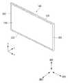
도 1 및 도 2는 본 발명의 일 실시예에 따른 디스플레이 장치를 도시한 도면이다.1 and 2 show a display device according to an embodiment of the present invention.
이들 도면에 도시한 바와 같이, 본 발명에 따른 디스플레이 장치(100)는, 디스플레이 패널(110) 및 디스플레이 패널(110) 후방의 백 커버(150)를 포함할 수 있다.As shown in these figures, the
백 커버(150)는, 제 1 장변(LS1)으로부터 제 2 장변(LS2)을 향하는 방향, 즉 제 2 방향(DR2)으로 슬라이딩(Sliding) 방식으로 디스플레이 패널(110)에 연결될 수 있다. 다르게 표현하면, 백 커버(150)는 디스플레이 패널(110)의 제 1 단변(SS1), 제 1 단변(SS1)에 대항되는 제 2 단변(SS2) 및 제 1, 2 단변(SS1, SS2)에 인접하고 제 1 단변(SS1)과 제 2 단변(SS2)의 사이에 위치하는 제 1 장변(LS1)으로부터 슬라이딩(Sliding) 방식으로 끼워질 수 있다.The
백 커버(150)를 디스플레이 패널(110)에 슬라이딩 방식으로 연결하기 위해, 백 커버(150) 및/또는 그에 인접한 다른 구조물에는 돌출부, 슬라이딩부, 결합부 등이 포함되어 있을 수 있다.In order to connect the
도 3 및 도 4는 본 발명과 관련된 디스플레이 장치의 구성을 나타내는 도면들이다.3 and 4 are views showing the configuration of a display device related to the present invention.
도 3에 도시한 바와 같이, 본 발명에 따른 디스플레이 장치(100)는 프론트 커버(105), 디스플레이 패널(110), 백라이트 유닛(120), 프레임(130), 백 커버(150)를 포함할 수 있다.3, the
프론트 커버(105)는 디스플레이 패널(110)의 전면과 측면 중 적어도 일부 영역을 덮을 수 있다. 프론트 커버(105)는 중앙이 비어있는 사각형의 액자 형상일 수 있다. 프론트 커버(105)의 중앙이 비어있기 때문에, 디스플레이 패널(110)의 화상을 외부로 표시할 수 있다.The
프론트 커버(105)는, 전면커버와 측면커버로 구분될 수 있다. 즉, 디스플레이 패널(110)의 전면(前面) 측에 위치하는 전면커버와, 디스플레이 패널(110)의 측면 측에 위치하는 측면커버로 구분될 수 있음을 의미한다. 전면커버와 측면커버는 따로 구성될 수 있다. 전면커버와 측면커버 중 어느 한쪽은 생략될 수 있다. 예를 들어, 미려한 디자인 등의 목적으로, 전면커버는 존재하지 않고 측면커버만 존재하는 경우가 가능할 수 있음을 의미한다.The
디스플레이 패널(110)은 디스플레이 장치(100)의 전면에 제공되며 영상이 표시될 수 있다. 디스플레이 패널(110)은 영상을 복수개의 픽셀로 나누어 각 픽셀당 색상, 명도, 채도를 맞추어 영상을 출력할 수 있다. 디스플레이 패널(110)은 영상이 표시되는 활성영역(active area)과 영상이 표시되지 않는 비활성 영역(inactive area)으로 구분될 수 있다. 디스플레이 패널(110)은 액정층을 사이에 두고 서로 대향하는 전면 기판 (front substrate) 및 후면 기판(rear substrate)을 포함할 수 있다.The
전면 기판은, 레드(R), 그린(G) 및 블루(B) 서브 픽셀로 이루어진 복수의 픽셀들을 포함할 수 있다. 전면 기판은 제어신호에 따라 레드, 그린, 또는 블루의 색에 해당하는 이미지를 발생시킬 수 있다.The front substrate may include a plurality of pixels made up of red (R), green (G), and blue (B) sub-pixels. The front substrate can generate an image corresponding to the color of red, green, or blue according to a control signal.
후면 기판은, 스위칭 소자들을 포함할 수 있다. 후면 기판은 화소전극을 스위칭할 수 있다. 예를 들어, 화소 전극은 외부에서 인가되는 제어신호에 따라 액정층의 분자배열을 변화시킬 수 있다. 액정층은 복수의 액정 분자들을 포함할 수 있다. 액정 분자들은 화소전극과 공통전극 사이에 발생된 전압 차에 상응하여 배열을 변화할 수 있다. 액정층은 백라이트 유닛(120)으로부터 제공되는 광을 전면 기판에 전달할 수 있다.The back substrate may include switching elements. The rear substrate can switch the pixel electrodes. For example, the pixel electrode can change the molecular arrangement of the liquid crystal layer according to a control signal applied from the outside. The liquid crystal layer may include a plurality of liquid crystal molecules. The liquid crystal molecules can change the arrangement in accordance with the voltage difference generated between the pixel electrode and the common electrode. The liquid crystal layer can transmit light provided from the
백라이트 유닛(120)은, 디스플레이 패널(110)의 후면 측에 위치할 수 있다. 백라이트 유닛(120)은, 복수의 광원(light source)을 포함할 수 있다. 백라이트 유닛(120)의 광원은, 직하형 또는 엣지형으로 배치되어 있을 수 있다. 엣지형 백라이트 유닛(120)인 경우에, 도광부(light guide panel)가 더 포함될 수 있다.The
백라이트 유닛(120)은, 프레임(140)의 전면측에 결합되어 있을 수 있다. 예를 들어, 복수의 광원(light source)이 프레임(140)의 전면측에 배치될 수 있음을 의미하며, 이와 같은 경우 직하형 백라이트유닛으로 통칭될 수 있다.The
백라이트 유닛(120)은 전체 구동 방식 또는 로컬 디밍(local dimming), 임펄시브(impulsive)등과 같은 부분 구동 방식으로 구동될 수 있다. 백라이트 유닛(120)은, 광학 시트(125, optical sheet)와 광학층(123)을 포함할 수 있다.The
광학 시트(125)는, 광원의 빛이 디스플레이 패널(110)로 고르게 전달되도록 할 수 있다. 광학 시트(125)는, 복수의 레이어로 구성될 수 있다. 예를 들어, 적어도 하나의 프리즘 시트 및/또는 적어도 하나의 확산 시트를 포함할 수 있다.The
광학 시트(125)에는, 적어도 하나의 결합부(125d)가 존재할 수 있다. 결합부(125d)는, 프론트 커버(105) 및/또는 백 커버(150)에 결합될 수 있다. 즉, 프론트 커버(105) 및/또는 백 커버(150)에 직접적으로 결합될 수 있음을 의미한다. 또는, 결합부(125d)는, 프론트 커버(105) 및/또는 백 커버(150) 상에 결합된 구조물에 결합될 수 있다. 즉, 프론트 커버(105) 및/또는 백 커버(150)에 간접적으로 결합될 수 있음을 의미한다.The
광학층(123)은, 광원 등을 포함할 수 있다. 광학층(123)의 구체적인 구성은 해당하는 부분에서 설명하도록 한다.The
프레임(130)은, 디스플레이 장치(100)의 구성품을 지지하는 역할을 할 수 있다. 예를 들어, 백라이트유닛(120) 등의 구성이 프레임(130)에 결합될 수 있다. 프레임(130)은, 알루미늄 합금 등의 금속재질로 구성될 수 있다.The
백 커버(150)는, 디스플페이 장치(100)의 후면에 위치할 수 있다. 백 커버(150)는, 내부의 구성을 외부로부터 보호할 수 있다.백 커버(150)의 적어도 일부는 프레임(130) 및/또는 프론트 커버(105)에 결합될 수 있다. 백 커버(150)는, 레진(resion) 재질의 사출물일 수 있다.The
도 4는, 광학 시트(125) 등의 구성을 도시한 도면이다.4 is a diagram showing the configuration of the
도 4의 (a)에 도시한 바와 같이, 프레임(130) 상부에 광학 시트(125)가 위치할 수 있다. 광학 시트(125)는 프레임(130)의 가장자리에서 프레임(130)과 결합할 수 있다. 광학 시트(125)는 프레임(130)의 가장자리에 직접 안착될 수 있다. 즉, 광학 시트(125)는 프레임(130)에 의해 지지될 수 있다. 반사 시트(125)의 가장자리 상부면은 제1 가이드 패널(117)에 의해 감싸질 수 있다. 예를 들어, 광학 시트(125)는 프레임(130)의 가장자리와 제1 가이드 패널(117)의 플랜지(117a)사이에 위치할 수 있다.As shown in Fig. 4 (a), the
광학 시트(125) 전면(前面) 측에는 디스플레이 패널(110)이 위치할 수 있다. 디스플레이 패널(110)의 가장자리는 제1 가이드 패널(117)에 결합될 수 있다. 즉, 디스플레이 패널(110)은 제1 가이드 패널(117)에 의해 지지될 수 있음을 의미한다.The
디스플레이 패널(110)의 전면(前面) 중 가장자리 영역은 프론트 커버(105)에 의해 감싸질 수 있다. 예를 들어, 디스플레이 패널(110)이 제1 가이드 패널(117)과 프론트 커버(105) 사이에 위치될 수 있음을 의미한다.An edge region of the front surface of the
도 4의 (b)에 도시한 바와 같이, 본 발명의 일 실시예에 따른 디스플레이 장치는(100), 제2 가이드 패널(113)을 더 포함할 수 있다. 광학 시트(125)는, 제2 가이드 패널(113)에 결합될 수 있다. 즉, 프레임(130)에 제2 가이드 패널(113)이 결합되고, 제2 가이드 패널(113)에 광학 시트(125)가 결합되는 형태일 수 있음을 의미한다. 제2 가이드 패널(113)은, 프레임(130)과 다른 재질일 수 있다. 프레임(130)은, 제1,2 가이드 패널(117, 113)을 감싸는 형태일 수 있다.As shown in FIG. 4 (b), the display device according to an embodiment of the present invention may further include a
도 4의 (c)에 도시한 바와 같이, 본 발명의 일 실시예에 따른 디스플레 장치(100)는, 프론트 커버(105)가 디스플레이 패널(110)의 전면을 덮지 않을 수 있다. 즉, 프론트 커버(105)의 일 끝단이 디스플레이 패널(110)의 측면에 위치될 수 있음을 의미한다.4C, the
도 5내지 도 15는 본 발명의 일 실시예에 따른 멀티 디스플레이 장치를 상세하게 나타내는 도면들이다.5 to 15 are views showing details of a multi-display device according to an embodiment of the present invention.
도 5에 도시한 바와 같이, 본 발명의 일 실시예에 따른 디스플레이 장치(100)는 후면 중심부가 지지 스탠드(130)에 연결될 수 있다. 디스플레이 장치(100) 후면 중심부의 와 지지 스탠드(130)와의 자세한 연결관계는 후술하도록 한다. 지지 스탠드(130)는 디스플레이 장치(100)를 지면에서 이격되도록 할 수 있으며, 지지 스탠드(130)는 디스플레이 장치(100)의 길이 방향으로 연장되다가 디스플레이 장치(100)의 두께 방향으로 더 연장될 수 있다.5, the
지지 스탠드(130)는 디스플레이 장치(100)의 두께 방향으로 연장되는 넓이가 넓을수록 무게 중심이 낮아지기 때문에, 디스플레이 장치(100)를 더 잘 지탱할 수 있다.The support stand 130 can support the
지지 스탠드(130)는 디스플레이 장치(100)의 일 지점과 연결되는 것이 도시되었지만, 이에 한정하지 아니하며 지지 스탠드(130)는 디스플레이 장치(100)의 좌우 또는 상하에 연결될 수 있다.The
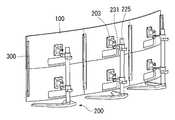
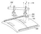
도 6은 본 발명에 따른 다열 스탠드를 나타내는 사시도이다.6 is a perspective view showing a multi-row stand according to the present invention.
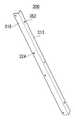
도 6을 참조하면, 다열 스탠드(200)는 디스플레이 장치(100)를 고정시킬 수 있다. 다열 스탠드(200)는 디스플레이 장치(100)의 위치를 자유롭게 조정하며 고정시킬 수 있다. 다열 스탠드(200)는 주기둥(215), 적어도 하나의 바(231), 받침부(283), 회전부(272) 및 베이스(213)를 포함할 수 있다.Referring to FIG. 6, the
주기둥(215)은 적어도 하나의 바(231) 및 베이스(213)와 연결될 수 있다. 주기둥(215)은 적어도 하나의 바(231)의 위치를 이동시킬 수 있다. 즉, 주기둥(215)은 디스플레이 장치(100)를 상하로 자유롭게 이동시킬 수 있음을 의미한다.The
주기둥(215)의 밑면을 받쳐주기 위해 베이스(213)가 위치할 수 있다. 베이스(213)는 폭이 클수록 무게중심이 낮아지기 때문에 주기둥(215)을 더 잘 지탱할 수 있다.The base 213 may be positioned to support the bottom surface of the
적어도 하나의 바(231)는 주기둥(215)의 적어도 일부에 연결될 수 있다. 이에 따라, 적어도 하나의 바(231)는 주기둥(215)을 감싸는 원통형상을 가지며 이로부터 회전부(272)까지 연장될 수 있다.At least one
적어도 하나의 바(231)는 주기둥(215)에 고정되기 위하여 하단에 파이프 링(225)이 위치할 수 있다. 파이프 링(225)의 나사를 풀면 적어도 하나의 바(231)는 상하로 자유롭게 이동할 수 있다.At least one
적어도 하나의 바(231)는 주기둥(215)에 고정되기 위하여 파이프 링(225)과 별도로 힌지로 고정될 수 있다. 자세한 힌지 구조에 관해서는 후술하도록 한다.At least one
적어도 하나의 바(231)는 일 단이 회전부(272)에 연결될 수 있다. 회전부(272)는 회전 함으로써 받침부(283)를 상하 및 좌우를 향하도록 할 수 있다. 회전부(272)는 약 위로 20도 아래로 30도 회전할 수 있다. 또한, 회전부(283)는 좌우로는 자유롭게 회전할 수 있다.At least one
받침부(283)는 회전부(272)와 직접 접해 있을 수 있다. 받침부(283)는 디스플레이 장치를 결합하는 부분일 수 있다. 받침부(283)는 디스플레이 장치를 안전하게 결합하기 위하여 넓은 면적을 차지할 수 있다. 일례로, 받침부(283)는 회전부(272)보다 더 넓은 사각형의 형상일 수 있다. 받침부(283)의 각 꼭지점 부근의 홀에 볼트를 결합하여 디스플레이 장치와 연결할 수 있다.The receiving
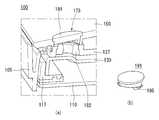
도 7을 참조하면, 커넥팅바(300)는 디스플레이 장치의 후면에 접하는 제 1 면(315)과 다른 커넥팅바(300)와 접하는 제 2 면(313)을 포함할 수 있다. 제 1 면(315)과 제 2 면(313)은 서로 직각을 이룰 수 있다. 다만 이에 한정하지 아니하며 제 1 면(315)과 제 2 면(313)은 예각 또는 둔각을 이룰 수도 있다.Referring to FIG. 7, the connecting
제 1 면(315)은 디스플레이 장치와 결합될 수 있다. 제 1 면(315)의 제 1결합 홀(324)에 볼트를 삽입하여 디스플레이 장치와 결합할 수 있다.The
제 2 면(313)은 다른 커넥팅바(300)의 제 2 면(313)과 결합할 수 있다. 제 2 면(313)은 제 2 결합 홀(352)에 볼트를 삽입하여 다른 커넥팅바(300)와 결합할 수 있다.The
제 1 면(315)과 제 2 면(313)의 상세한 결합관계는 후술하도록 한다.The detailed connection relationship between the
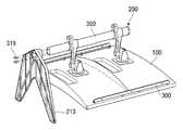
도 8을 참조하면, 두 개의 디스플레이 장치(100)가 다열 스탠드(200) 및커넥팅바(300)에 의해 일 면이 접할 수 있다. 즉, 두 개의 디스플레이 장치(100)가 서로 맞닿아 있다는 것을 의미한다.Referring to FIG. 8, two
각각의 디스플레이 장치(100)는 다열 스탠드(200)의 받침부(283)에 중심이 연결되며, 커넥팅바(300)에 의해 서로 결합될 수 있다. 도면에는 커넥팅바(300)에 의해 두 디스플레이 장치(100)가 공간 없이 접해있는 것으로 도시되어 있지만 이에 한정되지 않으며, 각각의 디스플레이 장치(100)는 서로 일정 간격 이격될 수도 있다.Each
도 9를 참조하면, 복수의 디스플레이 장치(100)가 다열 스탠드(200) 및 커넥팅바(300)에 의해 적어도 일 면이 접할 수 있다. 복수의 디스플레이 장치(100)는 상하로 위치한 디스플레이 장치(100)는 다열 스탠드(200)에 의해 서로 연결되며, 좌우에 위치한 디스플레이 장치(100)는 커넥팅바(300)에 의해 서로 연결될 수 있다.Referring to FIG. 9, at least one surface of the plurality of
좌우로 연결되는 디스플레이 장치(100)가 늘어날수록 커넥팅바(300)의 개수를 늘려 서로 연결할 수 있으며, 상하로 연결되는 디스플레이 장치(100)가 늘어날수록 다열 스탠드(200)의 바(231)의 개수를 늘려 서로 연결할 수 있다. 즉, 디스플레이 장치(100)가 늘어나더라도 서로 연결하는데 문제가 발생하지 않음을 의미한다.The number of the connecting
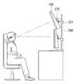
도 10을 참조하면, 본 발명에 따른 디스플레이 장치(100)는 회전부(272)의 상하 기울기를 조정하여 사용자를 향하도록 지향할 수 있다. 상세하게, 사용자의 눈높이에 위치한 디스플레이 장치(100)는 회전부(272)를 회전시키지 않고 그대로 유지하여 사용자를 향하게 하고, 사용자의 눈높이와 다른 부분에 위치한 디스플레이 장치(100)는 회전부(272)를 상하로 회전시켜 사용자를 향하게 할 수 있다.Referring to FIG. 10, the
각각의 디스플레이 장치(100)가 사용자를 향함에 따라 사용자는 디스플레이 장치(100)에 표시된 영상 또는 사진을 더 정확히 확인할 수 있다.As each
도 11을 참조하면, 본 발명에 따른 디스플레이 장치(100)는 회전부(272)의 좌우 기울기를 조정하여 사용자를 향하도록 지향할 수 있다. 상세하게, 사용자의 정면에 위치한 디스플레이 장치(100)는 회전부(272)를 회전시키지 않고 그대로 유지하여 사용자를 향하게 하고, 사용자의 정면에 위치하지 않은 디스플레이 장치(100)는 회전부(272)를 좌우로 회전시켜 사용자를 향하게 할 수 있다.Referring to FIG. 11, the
각각의 디스플레이 장치(100)는 상하방향과 달리 좌우방향으로 90도까지제한 없이 이동할 수 있기 때문에, 사용자의 위치와 상관없이 거의 자유롭게 이동할 수 있다.Unlike the vertical direction, each of the
도 12를 참조하면, 본 발명에 따른 디스플레이 장치(100)는 백커버(150)에 거치대(Supporter)를 결합하기 위한 복수의 홀이 마련될 수 있다.Referring to FIG. 12, the
예를 들어, 디스플레이 장치(100)의 양 측 끝에 복수의 제 1 홀(173)이 위치할 수 있다. 복수의 제 1 홀(173)은 측면에 접할 디스플레이 장치(100)를 연결하는 기능을 할 수 있다. 복수의 제 1 홀(173)의 자세한 연결관계에 관해서는 후술하도록 한다.For example, a plurality of
다른 예로, 디스플레이 장치(100)의 중심부에 복수의 제 2 홀(161)이 위치할 수 있다. 복수의 제 2 홀(161)은 거치대를 디스플레이 장치(100)에 연결하는 기능을 할 수 있다. 복수의 제 2 홀(161)의 자세한 연결관계에 관해서는 후술하도록 한다.As another example, a plurality of
본 발명에 따른 디스플레이 장치(100)는 복수개의 제 1,2 홀(173, 161)에 의해 거치대와 연결될 수 있다. 이에 따라, 사용자들이 필요에 따라 자유롭게 다른 장치를 사용하지 않고 다중 디스플레이 장치(100)를 구성할 수 있다.The
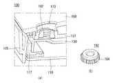
도 13을 참조하면, 본 발명에 따른 디스플레이 장치(100)는 프레임(130)과 백 커버(150) 사이에 미들 케비넷(137)이 위치할 수 있다. 미들 케비넷(137)은 내부에 결합공(182)이 실장될 수 있다. 결합공(182)은 원기둥의 형상을 할 수 있으며 일 면이 제 1 홀(173)을 통해 외부로 노출될 수 있다. 결합공(182)은 하부면이 더 돌출되어 미들 케비넷(137)에 끼워질 수 있다. 결합공(182)은 돌출된 하부면에 톱니문양(184)이 새겨질 수 있다. 톱니문양(184)은 결합공(182)이 미들 케비넷(137)에 더 잘 결합되도록 할 수 있다. 즉, 톱니문양(184)은 미들 케비넷(137)의 내부에 맞물릴 수 있음을 의미한다.Referring to FIG. 13, the
결합공(182)은 중심부에 홀을 포함할 수 있다. 결합공(182)의 홀은 디스플레이 장치(100)와 다른 연결 부재들을 결합하는 기능을 할 수 있다.The engaging
도 14를 참조하면, 본 발명에 따른 디스플레이 장치(100)는 결합공(182)이 외부로 노출되지 않도록 마감캡(191)이 백 커버(150) 상에 위치할 수 있다. 마감캡(191)은 제 1 홀(173) 에 끼워질 수 있다. 즉, 마감캡(191)은 제 1 홀(173)을 사용자에게 노출되지 않도록 할 수 있음을 의미한다. 마감캡(191)은 하단면에 좌우측으로 일정부분 돌출되어 있는 걸개(195)가 위치할 수 있다. 걸개(195)는 마감캡(191)이 백 커버(150)에서 쉽게 이탈하지 않도록 잡아줄 수 있다. 걸개(195)는 도면상에 마감캡(191)의 좌우측에 각각 하나씩 위치한 것으로 도시되었지만 이에 한정하지 아니하며, 걸개(195)는 마감캡(191)의 하단면에 복수개가 위치할 수도 있다.14, in the
마감캡(191)은 백 커버(150)에 결합했을 때, 백커버(150)와 마감캡(191)의 높이가 동일할 수 있다. 이에 따라, 사용자는 외부에서 바라봤을 때 외관이 깔끔해졌다고 인식할 수 있다.When the finishing
도 15를 참조하면, 본 발명에 따른 디스플레이 장치(100)는 백커버(150) 상에 결합너트(321)가 위치할 수 있다. 결합너트(321)는 상술한 마감캡(도 14의 191)을 제거한 후, 제 1 홀(173)에 끼워질 수 있다.Referring to FIG. 15, the
결합너트(321)는 결합공(182)과 결합하여 디스플레이 장치(100) 내부에 고정될 수 있다. 결합너트(321)는 육각형의 형상일 수 있다. 다만 이에 한정하지 아니하며, 결합너트(321)는 사각형, 삼각형 원형 등 다양한 형상일 수 있다. 결합너트(321)는 중심부에 홀을 포함할 수 있다. 결합너트(321)의 홀은 백 커버(150)의 후면에 커넥팅바를 결합할 때 사용될 수 있다. 자세한 결합관계는 후술하도록 한다.The engaging
결합너트(321)는 결합되었을 때 백 커버(150)보다 디스플레이 장치(100)의 두께 방향으로 돌출되어 있을 수 있다. 이는 사용자가 결합너트(321)를 커넥팅바와 결합할 때, 결합너트(321)를 쉽게 찾을 수 있게 할 수 있다.The engaging
도 16 내지 도 20은 본 발명의 일 실시예에 따른 멀티 디스플레이 장치의 결합 방법을 도시한 도면들이다.16 to 20 are views showing a method of combining a multi-display device according to an embodiment of the present invention.
도 16을 참조하면, 복수의 디스플레이 장치(100)가 적어도 일면이 접하여위치할 수 있다. 복수의 디스플레이 장치(100)를 결합하기 위하여 우선 제 1 홀(173)에서 마감캡(도 14의 195)를 분리한 후 결합너트(321)를 결합할 수 있다. 결합너트(321)는 복수의 디스플레이 장치(100)의 양 측에 결합될 수 있다.Referring to FIG. 16, at least one side of the plurality of
결합너트(321)를 결합한 후, 결합너트(321)의 상부면에 커넥팅바(300)가 마련될 수 있다. 커넥팅바(300)의 제 1 면(315)이 결합 너트(321)의 적어도 일 면과 접할 수 있다.After the
커넥팅바(300)를 결합너트(321)의 상부면에 위치시킨 후, 고정 나사(319)를 결합할 수 있다. 고정 나사(319)는 커넥팅바(300)의 제 1 면(315)을 관통하여 결합너트(321)와 결합될 수 있다. 고정 나사(319)는 결합너트(321)와 결합하여 커넥팅바(300)를 고정시킬 수 있다.After the connecting
도 17을 참조하면, 커넥팅바(300)을 복수의 디스플레이 장치(100)에 연결한 후, 다열 스탠드(200)를 복수의 디스플레이 장치(100)에 결합할 수 있다.17, after the connecting
상세하게, 받침부(283)의 홀에 디스플레이 장치(100)의 제 2 홀(161)에 맞추어 다열 스탠드(200)를 위치시킬 수 있다. 그 후에, 받침부(283)와 디스플레이 장치(100)를 고정 나사(319)에 의해 결합할 수 있다.In detail, the
도면 상에는 상부에 위치한 디스플레이 장치(100)가 다열 스탠드(200)와 결합하는 것이 도시되었지만, 하부에 위치한 디스플레이 장치(100)도 상부의 디스플레이 장치(100)가 결합한 후 같은 방법으로 다열 스탠드(200)와 결합될 수 있다.The
도 18을 참조하면, 다열 스탠드(200)를 복수의 디스플레이 장치(100)에 결합한 후에, 베이스(213)가 주기둥(215)에 결합할 수 있다. 베이스(213)가 주기둥(215)에 결합함에 따라 다열 스탠드(200)가 위치에서 이탈하지 않을 수 있다. 또한, 디스플레이 장치(100)가 좌우 또는 앞뒤로 기울어지지 않을 수 있다.18, after the
상세하게, 고정나사(319)는 베이스(213)의 하부면을 관통하여 주기둥(215)에 결합될 수 있다. 이에 따라, 베이스(213)가 주기둥(215)에 고정될 수 있다.In detail, the fixing
도 19를 참조하면, 적어도 하나의 바(231)와 파이프 링(225)을 주기둥(215)에 고정시킬 수 있다. 적어도 하나의 바(231)를 주기둥(215)에 고정하여 좌우로 이동하지 않도록 고정하며, 파이프 링(225)를 고정하여 적어도 하나의 바(231)가 상하로 이동하지 않도록 고정할 수 있다. 상세하게, 적어도 하나의 바(231)와 주기둥(215)는 제 1 렌치(412)에 의해 결합될 수 있다. 예를 들어, 제 1 렌치(412)는 2.5mm 렌치일 수 있다. 파이프링(225)과 주기둥(215)는 제 2 렌치(414)에 의해 결합될 수 있다. 예를 들어, 제 2 렌치(414)는 4mm 렌치일 수 있다.Referring to FIG. 19, at least one
적어도 하나의 바(231)와 파이프 링(225)이 주기둥(215)과 제 1,2 렌치(412, 414)를 이용하여 고정되기 때문에 사용자는 적어도 하나의 바(231)와 파이프 링(225)이 주기둥(215)과 쉽게 분리될 걱정을 하지 않을 수 있다.Since at least one
도 20을 참조하면, 마지막으로, 다열 스탠드(200)와 결합된 복수의 디스플레이 장치(100)과 다른 결합된 복수의 디스플레이 장치(100)를 연결할 수 있다. 복수의 디스플레이 장치(100)들은 커넥팅바(300)를 이용하여 연결할 수 있다.Referring to FIG. 20, finally, a plurality of
상세하게, 커넥팅바(300)의 제 2 면(313)끼리 고정 나사(319)와 너트(515)를 이용하여 결합할 수 있다.The second faces 313 of the connecting
커넥팅바(300)는 제 1 면(315)와 제 2 면(313)의 경계선에 제 2 면(313)에 수직하는 방향으로 돌출되어 있는 돌기(525)로 인하여 다른 커넥팅바(300)와 접하지 않을 수 있다. 또한, 고정 나사(319)의 커넥팅바(300) 사이에 위치한 부분에 스프링(527)이 위치하기 때문에 커넥팅바(300)가 서로 근접할 경우 탄성에 의해 거리가 멀어질 수 있다.The connecting
커넥팅바(300)의 돌기(525)와 스프링(527)에 의하여 디스플레이 장치(100)는 서로 접하지 않을 수 있다. 또한, 커넥팅바(300)는 돌기(525)와 스프링(527)에 의하여 미세한 간격을 조절하기 쉬워질 수 있다.The
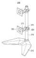
도 21은 본 발명의 다른 실시예에 따른 디스플레이 장치를 도시한 도면이다.21 is a view illustrating a display device according to another embodiment of the present invention.
도 21을 참고하면, 본 발명에 따른 디스플레이 장치(100)는 벽걸이의 용도로 사용되기 위하여 후면 중심부에 젠더(357)가 위치할 수 있다. 젠더(357)는 예를 들어 직사각형 또는 정사각형의 형상일 수 있다. 젠더(357)는 예를 들어 삼각형의 형상일 수도 있다.Referring to FIG. 21, the
젠더(357)는 디스플레이 장치(100)의 후면 중심부에 위치한 연결부재(471)와 결합할 수 있다. 연결부재(471)는 디스플레이 장치(100)의 두께 방향으로 돌출될 수 있다. 상세하게, 연결부재(471) 내의 안착홀(484)에 젠더(357)의 안내돌기(513)가 삽입될 수 있다. 안착홀(484)은 연결부재(471)의 내측으로 함몰되어 있으며, 안내돌기(513)는 젠더(357)에서 연결부재(471) 방향으로 돌출되어 있을 수 있다. 안착홀(484)에 안내돌기(513)가 삽입된 후에 고정나사에 의해 젠더(357)가 연결부재(471)에 고정될 수 있다.The
사용자는 젠더(357)에 의하여 견고한 벽걸이 디스플레이 장치(100)를 생산할 수 있으며, 벽걸이가 필요하지 않을 때, 젠더(357)를 연결부재(471)에서 분리하여 사용자로 하여금 깔끔한 외관을 인식되도록 할 수 있다. 연결부재(471)에 의하여 사용자들은 벽걸이를 사용할지 선택할 수 있으며, 가격 경쟁력이 확보될 수 있다.The user can produce the wall-mounted
상기의 상세한 설명은 모든 면에서 제한적으로 해석되어서는 아니되고 예시적인 것으로 고려되어야 한다. 본 발명의 범위는 첨부된 청구항의 합리적 해석에 의해 결정되어야 하고, 본 발명의 등가적 범위 내에서의 모든 변경은 본 발명의 범위에 포함된다.The foregoing detailed description should not be construed in all aspects as limiting and should be considered illustrative. The scope of the present invention should be determined by rational interpretation of the appended claims, and all changes within the scope of equivalents of the present invention are included in the scope of the present invention.
Claims (15)
Translated fromKorean상기 복수의 디스플레이 모듈의 후면에 결합되어 상기 복수의 디스플레이 모듈을 고정하는 다열 스탠드를 포함하며,
상기 다열 스탠드는,
베이스와,
상기 베이스 상에 세워진 주기둥과,
상기 주기둥에, 상기 주기둥의 결합방향과 다른 방향으로 적어도 하나가 이격 결합된 바와,
상기 적어도 하나의 바의 일 끝단에 지향방향을 전환할 수 있도록 연결된 회전부와,
일측은 상기 회전부에 결합되고 타측은 상기 디스플레이 모듈의 후면에 결합된 결합부를 포함하는 멀티 디스플레이 장치.
A plurality of display modules; And
And a multi-row stand coupled to a rear surface of the plurality of display modules to fix the plurality of display modules,
The multi-
A base,
A main column laid on the base,
At least one of which is spaced apart from the main column in a direction different from a direction of engagement of the main column,
A rotating part connected to one end of the at least one bar so as to be able to switch a direction of the direction,
And a coupling portion coupled to a rear side of the display module, the other side coupled to the rotation portion.
상기 디스플레이 모듈은,
상기 디스플레이 모듈 후면의 적어도 한 모서리 영역을 따라 상기 디스플레이 모듈의 두께 방향으로 함몰된 적어도 하나의 제 1 홀을 포함하는 멀티 디스플레이 장치.
The method according to claim 1,
The display module includes:
And at least one first hole recessed in the thickness direction of the display module along at least one corner area of the back surface of the display module.
상기 디스플레이 모듈은,
상기 디스플레이 모듈의 백 커버에 결합되어 상기 제 1 홀을 차폐하는 마감캡을 더 포함하되,
상기 마감캡은,
상기 백 커버에 형성된 통공에 결합되는 걸개를 포함하는 멀티 디스플레이 장치.
3. The method of claim 2,
The display module includes:
And a finishing cap coupled to the back cover of the display module to shield the first hole,
The closure cap
And a hanging portion coupled to the through hole formed in the back cover.
상기 디스플레이 모듈은,
상기 디스플레이 모듈의 중심 영역의 상기 디스플레이 모듈의 두께 방향으로 함몰된 적어도 하나의 제 2 홀을 포함하는 멀티 디스플레이 장치.
The method according to claim 1,
The display module includes:
And at least one second hole recessed in the thickness direction of the display module in a central area of the display module.
상기 복수의 디스플레이 모듈의 후면 중 적어도 하나의 적어도 일측에 결합되는 커넥팅바(connecting bar)를 더 포함하는 멀티 디스플레이 장치.
The method according to claim 1,
And a connecting bar coupled to at least one side of at least one of the rear surfaces of the plurality of display modules.
상기 커넥팅바는,
상기 디스플레이 모듈 후면의 적어도 한 모서리 영역을 따라 상기 디스플레이 모듈의 두께 방향으로 함몰된 적어도 하나의 제 1 홀에 결합된 적어도 하나의 결합너트에 결합되는 멀티 디스플레이 장치.
6. The method of claim 5,
Wherein the connecting bar comprises:
And at least one coupling nut coupled to at least one first hole recessed in the thickness direction of the display module along at least one edge region of the backside of the display module.
상기 커넥팅바 중 적어도 하나는 상기 복수의 디스플레이 모듈 중 어느 하나에 결합되고, 상기 커넥팅바 중 적어도 다른 하나는 상기 복수의 디스플레이 모듈 중 다른 하나에 결합되며,
상기 어느 하나와 상기 다른 하나의 커넥팅바는, 상호 결합되어 상기 복수의 디스플레이 장치 중 상기 어느 하나와 상기 다른 하나의 디스플레이 모듈을 고정하는 멀티 디스플레이 장치.
6. The method of claim 5,
Wherein at least one of the connecting bars is coupled to one of the plurality of display modules and at least another one of the connecting bars is coupled to another one of the plurality of display modules,
Wherein one of the plurality of display devices and the other one of the plurality of display devices are coupled to each other to fix the one of the plurality of display devices and the other display module.
상기 커넥팅바는,
제 1 면과,
상기 제1 면과 실질적으로 수직한 방향으로 연장된 제 2 면을 포함하는 디스플레이 장치.
6. The method of claim 5,
Wherein the connecting bar comprises:
A first surface,
And a second surface extending in a direction substantially perpendicular to the first surface.
상기 커넥팅바 중 적어도 하나와 다른 하나가 상호 접하지 않도록,
상기 커넥팅바 중 적어도 하나의 상기 제 2 면과 상기 커넥팅바 중 다른 하나의 상기 제 2 면 사이에 위치한 스프링을 더 포함하는 멀티 디스플레이 장치.
9. The method of claim 8,
So that at least one of the connecting bars and the other one of the connecting bars do not contact each other,
And a spring positioned between the second surface of at least one of the connecting bars and the second surface of the other of the connecting bars.
상기 제 1 면과 상기 제 2 면의 경계영역에,
상기 커넥팅바 중 적어도 하나와 다른 하나가 상호 접하지 않도록,
상기 커넥팅바 중 적어도 하나의 제 2 면과 상기 커넥팅바 중 다른 하나의 제 2 면 사이에 위치한 돌기를 더 포함하는 멀티 디스플레이 장치.
9. The method of claim 8,
And a boundary region between the first surface and the second surface,
So that at least one of the connecting bars and the other one of the connecting bars do not contact each other,
And a projection located between a second surface of at least one of the connecting bars and a second surface of the other of the connecting bars.
상기 회전부 중 적어도 하나는,
상기 회전부 중 다른 하나와 지향방향이 다른 디스플레이 장치.
The method according to claim 1,
Wherein at least one of the rotating parts comprises:
And a direction of a direction different from that of the other one of the rotating parts.
상기 베이스 상에 세워진 주기둥;
상기 주기둥에, 상기 주기둥의 결합방향과 다른 방향으로 적어도 하나가 이격 결합된 바;
상기 적어도 하나의 바의 일 끝단에 지향방향을 전환할 수 있도록 연결된 회전부;
일측은 상기 회전부에 결합되고 타측은 디스플레이 모듈의 후면에 결합된 결합부를 포함하는 다열 스탠드.
Base;
A main column mounted on the base;
At least one bar spaced apart from the main column in a direction different from a direction in which the main column is joined;
A rotating part connected to one end of the at least one bar so as to be capable of switching a direction of the direction;
And a coupling part coupled to a rear side of the display module, the other side coupled to the rotation part.
상기 회전부 중 적어도 하나는,
상기 회전부 중 다른 하나와 지향방향이 다른 다열 스탠드.
13. The method of claim 12,
Wherein at least one of the rotating parts comprises:
And a direction of the other of the rotating parts is different from that of the other rotating part.
상기 바의 하단에 상기 바를 상기 주기둥에 고정시켜주는 파이프 링을 더 포함하는 다열 스탠드.
13. The method of claim 12,
And a pipe ring for fixing the bar to the main column at a lower end of the bar.
상기 결합부는,
상기 디스플레이 모듈 중심 영역의 제 2 홀과 결합하는 다열 스탠드.13. The method of claim 12,
The coupling portion
And a second hole in the central area of the display module.
Priority Applications (1)
| Application Number | Priority Date | Filing Date | Title |
|---|---|---|---|
| KR1020150032710AKR102292056B1 (en) | 2015-03-09 | 2015-03-09 | Multi display apparatus |
Applications Claiming Priority (1)
| Application Number | Priority Date | Filing Date | Title |
|---|---|---|---|
| KR1020150032710AKR102292056B1 (en) | 2015-03-09 | 2015-03-09 | Multi display apparatus |
Publications (2)
| Publication Number | Publication Date |
|---|---|
| KR20160109057Atrue KR20160109057A (en) | 2016-09-21 |
| KR102292056B1 KR102292056B1 (en) | 2021-08-23 |
Family
ID=57080305
Family Applications (1)
| Application Number | Title | Priority Date | Filing Date |
|---|---|---|---|
| KR1020150032710AActiveKR102292056B1 (en) | 2015-03-09 | 2015-03-09 | Multi display apparatus |
Country Status (1)
| Country | Link |
|---|---|
| KR (1) | KR102292056B1 (en) |
Cited By (1)
| Publication number | Priority date | Publication date | Assignee | Title |
|---|---|---|---|---|
| WO2022085964A1 (en)* | 2020-10-23 | 2022-04-28 | 엘지전자 주식회사 | Display control module and display apparatus comprising same |
Citations (4)
| Publication number | Priority date | Publication date | Assignee | Title |
|---|---|---|---|---|
| US6343006B1 (en)* | 1998-11-20 | 2002-01-29 | Jerry Moscovitch | Computer display screen system and adjustable screen mount, and swinging screens therefor |
| KR101254602B1 (en)* | 2012-07-27 | 2013-04-15 | 주식회사 오리온 | Display panel apparatus having position align function |
| KR20140035741A (en)* | 2012-09-14 | 2014-03-24 | 엘지전자 주식회사 | Multi display apparatus |
| KR20150024041A (en)* | 2013-08-26 | 2015-03-06 | 엘지디스플레이 주식회사 | Backlight Unit and Display Device Using The Backlight Unit |
- 2015
- 2015-03-09KRKR1020150032710Apatent/KR102292056B1/enactiveActive
Patent Citations (4)
| Publication number | Priority date | Publication date | Assignee | Title |
|---|---|---|---|---|
| US6343006B1 (en)* | 1998-11-20 | 2002-01-29 | Jerry Moscovitch | Computer display screen system and adjustable screen mount, and swinging screens therefor |
| KR101254602B1 (en)* | 2012-07-27 | 2013-04-15 | 주식회사 오리온 | Display panel apparatus having position align function |
| KR20140035741A (en)* | 2012-09-14 | 2014-03-24 | 엘지전자 주식회사 | Multi display apparatus |
| KR20150024041A (en)* | 2013-08-26 | 2015-03-06 | 엘지디스플레이 주식회사 | Backlight Unit and Display Device Using The Backlight Unit |
Cited By (2)
| Publication number | Priority date | Publication date | Assignee | Title |
|---|---|---|---|---|
| WO2022085964A1 (en)* | 2020-10-23 | 2022-04-28 | 엘지전자 주식회사 | Display control module and display apparatus comprising same |
| KR20220053903A (en)* | 2020-10-23 | 2022-05-02 | 엘지전자 주식회사 | Display control module and display device including same |
Also Published As
| Publication number | Publication date |
|---|---|
| KR102292056B1 (en) | 2021-08-23 |
Similar Documents
| Publication | Publication Date | Title |
|---|---|---|
| US10001670B2 (en) | Supporting member for backlight unit, backlight unit and image display apparatus having the same | |
| WO2010079588A1 (en) | Fixing structure and fixing method of multi-screen display device | |
| EP3015907B1 (en) | Display apparatus | |
| KR102330105B1 (en) | Display device | |
| US9733506B2 (en) | Liquid crystal display apparatus and dual-monitor setting method | |
| KR102373178B1 (en) | Display apparatus | |
| US10034399B2 (en) | Display device | |
| WO2014153802A1 (en) | Multi-screen display | |
| US9320157B2 (en) | Display device | |
| CN104575279B (en) | A kind of display device frame and display device | |
| US10928676B2 (en) | Display device | |
| US10921647B2 (en) | Display device | |
| KR20140114201A (en) | Bendable Display Device | |
| JP5599569B2 (en) | Autostereoscopic display | |
| KR20160109057A (en) | Multi display apparatus | |
| US10620476B2 (en) | Image display apparatus | |
| JP2009527788A5 (en) | ||
| US20070091554A1 (en) | Display device | |
| KR101236239B1 (en) | Liquid crystal display device module | |
| KR20090061467A (en) | Dual monitor unit | |
| CN101960213A (en) | Lighting devices, display devices and television receivers | |
| KR200327926Y1 (en) | Apparatus for fixing a flat display apparatus on the wall | |
| KR20210041230A (en) | Display device | |
| US10698258B2 (en) | Liquid crystal display device and split-type backlight module | |
| US20160139714A1 (en) | Transparent Display Device |
Legal Events
| Date | Code | Title | Description |
|---|---|---|---|
| PA0109 | Patent application | St.27 status event code:A-0-1-A10-A12-nap-PA0109 | |
| PN2301 | Change of applicant | St.27 status event code:A-3-3-R10-R13-asn-PN2301 St.27 status event code:A-3-3-R10-R11-asn-PN2301 | |
| PG1501 | Laying open of application | St.27 status event code:A-1-1-Q10-Q12-nap-PG1501 | |
| P22-X000 | Classification modified | St.27 status event code:A-2-2-P10-P22-nap-X000 | |
| A201 | Request for examination | ||
| PA0201 | Request for examination | St.27 status event code:A-1-2-D10-D11-exm-PA0201 | |
| PN2301 | Change of applicant | St.27 status event code:A-3-3-R10-R13-asn-PN2301 St.27 status event code:A-3-3-R10-R11-asn-PN2301 | |
| D13-X000 | Search requested | St.27 status event code:A-1-2-D10-D13-srh-X000 | |
| D14-X000 | Search report completed | St.27 status event code:A-1-2-D10-D14-srh-X000 | |
| E902 | Notification of reason for refusal | ||
| PE0902 | Notice of grounds for rejection | St.27 status event code:A-1-2-D10-D21-exm-PE0902 | |
| E13-X000 | Pre-grant limitation requested | St.27 status event code:A-2-3-E10-E13-lim-X000 | |
| P11-X000 | Amendment of application requested | St.27 status event code:A-2-2-P10-P11-nap-X000 | |
| P13-X000 | Application amended | St.27 status event code:A-2-2-P10-P13-nap-X000 | |
| E701 | Decision to grant or registration of patent right | ||
| PE0701 | Decision of registration | St.27 status event code:A-1-2-D10-D22-exm-PE0701 | |
| PR0701 | Registration of establishment | St.27 status event code:A-2-4-F10-F11-exm-PR0701 | |
| PR1002 | Payment of registration fee | St.27 status event code:A-2-2-U10-U11-oth-PR1002 Fee payment year number:1 | |
| PG1601 | Publication of registration | St.27 status event code:A-4-4-Q10-Q13-nap-PG1601 | |
| PR1001 | Payment of annual fee | St.27 status event code:A-4-4-U10-U11-oth-PR1001 Fee payment year number:4 | |
| PR1001 | Payment of annual fee | St.27 status event code:A-4-4-U10-U11-oth-PR1001 Fee payment year number:5 |