KR20160105829A - Infusion catheter tip for biologics with reinforced external balloon valve - Google Patents
Infusion catheter tip for biologics with reinforced external balloon valveDownload PDFInfo
- Publication number
- KR20160105829A KR20160105829AKR1020167020515AKR20167020515AKR20160105829AKR 20160105829 AKR20160105829 AKR 20160105829AKR 1020167020515 AKR1020167020515 AKR 1020167020515AKR 20167020515 AKR20167020515 AKR 20167020515AKR 20160105829 AKR20160105829 AKR 20160105829A
- Authority
- KR
- South Korea
- Prior art keywords
- catheter
- separator
- balloon
- particles
- lumen
- Prior art date
- Legal status (The legal status is an assumption and is not a legal conclusion. Google has not performed a legal analysis and makes no representation as to the accuracy of the status listed.)
- Ceased
Links
- 238000001802infusionMethods0.000titleclaimsdescription27
- 229960000074biopharmaceuticalDrugs0.000title1
- 239000002245particleSubstances0.000claimsabstractdescription81
- 239000012530fluidSubstances0.000claimsabstractdescription78
- 230000003014reinforcing effectEffects0.000claimsabstractdescription13
- 239000007924injectionSubstances0.000claimsdescription36
- 238000002347injectionMethods0.000claimsdescription36
- 230000002792vascularEffects0.000claimsdescription29
- 239000008280bloodSubstances0.000claimsdescription16
- 210000004369bloodAnatomy0.000claimsdescription16
- 238000004891communicationMethods0.000claimsdescription13
- 210000000130stem cellAnatomy0.000claimsdescription13
- 230000017531blood circulationEffects0.000claimsdescription5
- 238000000034methodMethods0.000claimsdescription4
- 239000003795chemical substances by applicationSubstances0.000claimsdescription2
- 230000002787reinforcementEffects0.000claimsdescription2
- 230000008878couplingEffects0.000claims1
- 238000010168coupling processMethods0.000claims1
- 238000005859coupling reactionMethods0.000claims1
- 238000001415gene therapyMethods0.000claims1
- 238000009163protein therapyMethods0.000claims1
- 238000005054agglomerationMethods0.000abstractdescription3
- 230000002776aggregationEffects0.000abstractdescription3
- 239000003814drugSubstances0.000description16
- 210000004204blood vesselAnatomy0.000description13
- 229940124597therapeutic agentDrugs0.000description13
- 210000004027cellAnatomy0.000description11
- 238000001990intravenous administrationMethods0.000description10
- 239000000463materialSubstances0.000description9
- 230000001276controlling effectEffects0.000description5
- 238000001361intraarterial administrationMethods0.000description5
- 108090000623proteins and genesProteins0.000description5
- 210000005166vasculatureAnatomy0.000description5
- 238000011144upstream manufacturingMethods0.000description4
- 230000004931aggregating effectEffects0.000description3
- 230000008901benefitEffects0.000description3
- 230000003833cell viabilityEffects0.000description3
- 229940079593drugDrugs0.000description3
- 208000010125myocardial infarctionDiseases0.000description3
- 102000004169proteins and genesHuman genes0.000description3
- 230000001225therapeutic effectEffects0.000description3
- 208000027418Wounds and injuryDiseases0.000description2
- 238000004026adhesive bondingMethods0.000description2
- 230000003466anti-cipated effectEffects0.000description2
- 239000012620biological materialSubstances0.000description2
- 210000000748cardiovascular systemAnatomy0.000description2
- 238000010276constructionMethods0.000description2
- 230000008602contractionEffects0.000description2
- 230000006378damageEffects0.000description2
- 239000006185dispersionSubstances0.000description2
- 239000003978infusion fluidSubstances0.000description2
- 208000014674injuryDiseases0.000description2
- 230000014759maintenance of locationEffects0.000description2
- -1polyethylenePolymers0.000description2
- 229920000139polyethylene terephthalatePolymers0.000description2
- 239000005020polyethylene terephthalateSubstances0.000description2
- 239000004677NylonSubstances0.000description1
- 239000004698PolyethyleneSubstances0.000description1
- 230000002411adverseEffects0.000description1
- 210000001367arteryAnatomy0.000description1
- 238000001815biotherapyMethods0.000description1
- 230000004087circulationEffects0.000description1
- 238000013461designMethods0.000description1
- 238000009826distributionMethods0.000description1
- 230000009977dual effectEffects0.000description1
- 238000005189flocculationMethods0.000description1
- 230000016615flocculationEffects0.000description1
- 230000001771impaired effectEffects0.000description1
- 238000002513implantationMethods0.000description1
- 230000002452interceptive effectEffects0.000description1
- 238000002642intravenous therapyMethods0.000description1
- 238000004519manufacturing processMethods0.000description1
- 230000004048modificationEffects0.000description1
- 238000012986modificationMethods0.000description1
- 229920001778nylonPolymers0.000description1
- 229920000573polyethylenePolymers0.000description1
- 230000002265preventionEffects0.000description1
- 230000001105regulatory effectEffects0.000description1
- 230000004044responseEffects0.000description1
- 238000000926separation methodMethods0.000description1
- 239000002356single layerSubstances0.000description1
- 238000005728strengtheningMethods0.000description1
- 210000003462veinAnatomy0.000description1
Images


Classifications
- A—HUMAN NECESSITIES
- A61—MEDICAL OR VETERINARY SCIENCE; HYGIENE
- A61M—DEVICES FOR INTRODUCING MEDIA INTO, OR ONTO, THE BODY; DEVICES FOR TRANSDUCING BODY MEDIA OR FOR TAKING MEDIA FROM THE BODY; DEVICES FOR PRODUCING OR ENDING SLEEP OR STUPOR
- A61M25/00—Catheters; Hollow probes
- A61M25/10—Balloon catheters
- A61M25/1002—Balloon catheters characterised by balloon shape
- A—HUMAN NECESSITIES
- A61—MEDICAL OR VETERINARY SCIENCE; HYGIENE
- A61M—DEVICES FOR INTRODUCING MEDIA INTO, OR ONTO, THE BODY; DEVICES FOR TRANSDUCING BODY MEDIA OR FOR TAKING MEDIA FROM THE BODY; DEVICES FOR PRODUCING OR ENDING SLEEP OR STUPOR
- A61M25/00—Catheters; Hollow probes
- A61M25/0067—Catheters; Hollow probes characterised by the distal end, e.g. tips
- A61M25/0068—Static characteristics of the catheter tip, e.g. shape, atraumatic tip, curved tip or tip structure
- A61M25/0071—Multiple separate lumens
- A—HUMAN NECESSITIES
- A61—MEDICAL OR VETERINARY SCIENCE; HYGIENE
- A61M—DEVICES FOR INTRODUCING MEDIA INTO, OR ONTO, THE BODY; DEVICES FOR TRANSDUCING BODY MEDIA OR FOR TAKING MEDIA FROM THE BODY; DEVICES FOR PRODUCING OR ENDING SLEEP OR STUPOR
- A61M25/00—Catheters; Hollow probes
- A61M25/10—Balloon catheters
- A61M2025/1043—Balloon catheters with special features or adapted for special applications
- A61M2025/1084—Balloon catheters with special features or adapted for special applications having features for increasing the shape stability, the reproducibility or for limiting expansion, e.g. containments, wrapped around fibres, yarns or strands
- A—HUMAN NECESSITIES
- A61—MEDICAL OR VETERINARY SCIENCE; HYGIENE
- A61M—DEVICES FOR INTRODUCING MEDIA INTO, OR ONTO, THE BODY; DEVICES FOR TRANSDUCING BODY MEDIA OR FOR TAKING MEDIA FROM THE BODY; DEVICES FOR PRODUCING OR ENDING SLEEP OR STUPOR
- A61M25/00—Catheters; Hollow probes
- A61M25/10—Balloon catheters
- A61M2025/1043—Balloon catheters with special features or adapted for special applications
- A61M2025/1097—Balloon catheters with special features or adapted for special applications with perfusion means for enabling blood circulation only while the balloon is in an inflated state, e.g. temporary by-pass within balloon
- A—HUMAN NECESSITIES
- A61—MEDICAL OR VETERINARY SCIENCE; HYGIENE
- A61M—DEVICES FOR INTRODUCING MEDIA INTO, OR ONTO, THE BODY; DEVICES FOR TRANSDUCING BODY MEDIA OR FOR TAKING MEDIA FROM THE BODY; DEVICES FOR PRODUCING OR ENDING SLEEP OR STUPOR
- A61M2202/00—Special media to be introduced, removed or treated
- A61M2202/04—Liquids
- A61M2202/0413—Blood
- A61M2202/0429—Red blood cells; Erythrocytes
- A61M2202/0437—Blood stem cells
- A—HUMAN NECESSITIES
- A61—MEDICAL OR VETERINARY SCIENCE; HYGIENE
- A61M—DEVICES FOR INTRODUCING MEDIA INTO, OR ONTO, THE BODY; DEVICES FOR TRANSDUCING BODY MEDIA OR FOR TAKING MEDIA FROM THE BODY; DEVICES FOR PRODUCING OR ENDING SLEEP OR STUPOR
- A61M2206/00—Characteristics of a physical parameter; associated device therefor
- A61M2206/10—Flow characteristics
- A61M2206/18—Coaxial flows, e.g. one flow within another
Landscapes
- Health & Medical Sciences (AREA)
- Life Sciences & Earth Sciences (AREA)
- Heart & Thoracic Surgery (AREA)
- Hematology (AREA)
- General Health & Medical Sciences (AREA)
- Anesthesiology (AREA)
- Biomedical Technology (AREA)
- Pulmonology (AREA)
- Biophysics (AREA)
- Animal Behavior & Ethology (AREA)
- Engineering & Computer Science (AREA)
- Public Health (AREA)
- Veterinary Medicine (AREA)
- Child & Adolescent Psychology (AREA)
- Media Introduction/Drainage Providing Device (AREA)
- Infusion, Injection, And Reservoir Apparatuses (AREA)
- Materials For Medical Uses (AREA)
Abstract
Translated fromKoreanDescription
Translated fromKorean본 출원은 현재 모두 계류중인 2009년 9월 21일자 출원된 미국 특허출원 제12/563,876호의 일부 계속출원인, 2012년 5월 17일자 출원된 미국 특허출원 제13/473,988호의 일부 계속출원이며, 미국 특허출원 제13/473,988호 및 제12/563,876호의 내용은 모두 참조에 의해 본원에 통합된다.This application is a continuation-in-part of U.S. Patent Application No. 13 / 473,988, filed May 17, 2012, which is a continuation-in-part of U.S. Patent Application No. 12 / 563,876 filed September 21, 2009, The contents of applications 13 / 473,988 and 12 / 563,876 are all incorporated herein by reference.
본 발명은 대체로 유체 스트림 내로 입자를 도입하기 위한 주입 시스템들에 관한 것이다. 특히, 본 발명은 생물학적 물질(예를 들어, 줄기세포)의 치료 유효성을 감소시킴이 없이 환자의 혈관계(vasculature) 내로 생물학적 물질의 입자를 도입(주입)하기 위한 주입 시스템에 관한 것이다. 본 발명은 전적으로는 아니지만, 환자의 혈관계 내로 후속의 주입을 위하여 입자들이 개별적으로 또는 작은 그룹으로 분리기의 루멘에 들어가는 것을 가능하게 하는 멀티루멘 필터(multilumen filter)를 사용하는 시스템으로서 특히 유용하다.The present invention generally relates to infusion systems for introducing particles into a fluid stream. In particular, the invention relates to an infusion system for introducing (injecting) particles of biological material into the vasculature of a patient without reducing the therapeutic effectiveness of the biological material (e. G., Stem cells). The present invention is particularly useful as a system using a multilumen filter that allows the particles to enter the lumen of the separator individually or in small groups for subsequent infusion into the patient's vascular system.
환자의 혈관계 내로 입자의 도입은 몇몇 상이한 관심사 또는 고려를 동시에 만족시킬 것을 요구한다. 관련된 입자들의 형태에 의존하여, 상당히 중요한 관심사는 입자들이 혈관계 내로 주입 또는 도입됨에 따라서 응집되는 것, 즉 서로 덩어리짓는 것을 방지하는 것을 포함한다. 이러한 것은, 응집할 수 있는 줄기세포의 경우에 특정한 관심사이며, 그러나, 줄기세포는 개별 세포로서 또는 세포의 작은 그룹으로 기능하도록 두면 치료에 가장 효과적이다. 입자들이 응집되는 것을 방지하는 추가의 이점은 세포의 덩어리들이 관상동맥 순환 시스템(coronary circulatory system) 내로 도입될 때 유발되는 심근경색의 방지이다. 또한, 밸브 또는 풍선이 혈류를 감소시키는데 도움이 될 수 있을 때 유동이 느린 동안 줄기세포가 주입될 때, 심장 또는 다른 목표 조직에서의 줄기세포의 내부 유보율(retention rate)이 증가할 것이라는 것이 가능하다.The introduction of particles into the vascular system of a patient requires several different concerns or concerns to be satisfied at the same time. Depending on the type of particles involved, a considerable concern includes preventing the particles from agglomerating as they are injected or introduced into the vascular system, i. E., Preventing them from agglomerating one another. This is a particular concern in the case of stem cells that can aggregate, but it is most effective in treating stem cells if they are made to function as individual cells or as small groups of cells. A further advantage of preventing particles from agglomerating is the prevention of myocardial infarction caused when lumps of cells are introduced into the coronary circulatory system. It is also possible that the internal retention rate of stem cells in the heart or other target tissues will increase when the stem cells are injected while the flow is slow when the valve or balloon can help to reduce blood flow .
모든 형태의 혈관내 치료(즉, 관상동맥내(intracoronary), 동맥내(intra-arterial), 또는 정맥내(intravenous))에서, 치료제(예를 들어, 생물학적 치료제 또는 약제)가 예측 가능하게 제어된 방식으로 주입 또는 전달되는 것은 항상 본질적인 관심사이다. 또한, 치료제가 혈관계에서 적절한 목적지로 효과적으로 전달되는 것은 중요하다. 이러한 것 모두는 투여 및 전달율 고려 사항을 수반한다. 더욱이, 치료제가 주입 동안 손상되지 않거나 또는 그렇지 않으면 더럽혀지지 않는 것을 보장하도록 치료제의 신중한 취급을 요구한다.It is well known that in all types of intravascular treatment (i. E., Intracoronary, intra-arterial, or intravenous), the therapeutic agent (e.g., biological therapeutic agent or agent) It is always an intrinsic concern to be injected or delivered in such a way. It is also important that the therapeutic agent is effectively delivered from the vascular system to the appropriate destination. All of these involve administration and delivery rate considerations. Moreover, careful handling of the therapeutic agent is required to ensure that the therapeutic agent is not impaired or otherwise undetected during injection.
기계적인 관점으로부터, 유체 통로의 지름이 통로를 통한 유체 유량에 영향을 주는 인자라는 것이 공지되어 있다. 작은 그룹의 해교된(de-flocculated) 입자들이 혈관계의 혈관 내로 주입되는 프로토콜에 대하여, 통로의 지름은 명백하게 작은 그룹의 입자들을 개별적으로 수용하도록 충분히 커야만 한다. 다른 한편으로, 통로는 보다 큰 그룹의 입자(세포)들을 분리하여 서로 달라붙는 것을 방지하도록 또한 충분히 작아야 한다. 그 결과, 입자들이 통로를 통해 운반되는 속도는 통로의 지름에 의해 제한될 것이다. 추가의 관심사는, 입자들이 통로를 떠남에 따라서, 입자들이 그런 다음 혈관계의 혈관에서 유체(즉, 혈액)의 유동에 의해 영향을 받는다는 것이다. 프로토콜의 목적에 의존하여, 이러한 것은 혈관계에서 하류의 유체 유동이 어떻게든 조절될 필요가 있다는 것을 또한 의미한다.From a mechanical point of view, it is known that the diameter of the fluid passage is a factor that affects the fluid flow rate through the passage. For a protocol in which a small group of de-flocculated particles are injected into the blood vessel vasculature, the diameter of the passageway must be large enough to accommodate an apparently small group of particles individually. On the other hand, the passageway must also be small enough to separate the larger group of particles (cells) and prevent them from sticking together. As a result, the rate at which particles are transported through the passage will be limited by the diameter of the passage. An additional concern is that as the particles leave the passageway, the particles are then influenced by the flow of fluid (i. E., Blood) in the blood vessels of the vascular system. Depending on the purpose of the protocol, this also means that downstream fluid flow in the vascular system needs to be regulated somehow.
일부의 경우에, 혈관계에서 하류의 유체 유동(상기된 바와 같은)은 카테터 튜브의 외부면에 부착된 팽창 가능한 풍선을 사용하여 제어되거나 또는 조절될 수 있다. 이들 및 유사한 배열을 위하여, 풍선이 치료 부위에서 전개(즉, 팽창)될 때, 카테터 튜브 상에서 압력이 발휘된다. 그러나, 카테터 튜브는 카테터가 환자의 혈관계를 통하여 돌아다님에 따라서 비틀리고 회전하는 것을 허용하도록 전형적으로 가요성 재료로 만들어진다. 카테터 튜브의 가요성 특성 때문에, 풍선의 팽창 동안 뒤틀림(kinking) 및/또는 붕괴에 민감하다. 이러한 것은 특히 주입되는 재료가 카테터 튜브의 중앙 루멘을 통하여 펌핑되는 주입 카테터에 대해 특히 고질적일 수 있다. 이러한 예에서, 풍선이 팽창되는 중앙 루멘의 붕괴 또는 심지어 부분적인 차단은 중앙 루멘에서 유체 유동을 방해할 수 있으며, 주입 절차에 악영향을 미칠 수 있다. 유동을 감소시키는 것에 더하여, 붕괴 또는 차단된 카테터 튜브 루멘은 응력에 세포를 노출시키는 것에 의해 루멘을 통한 운반 동안 세포 생존성을 감소시킬 수 있다(주의: 일부 경우에, 생존성은 유동이 중앙 루멘에서 방해받을 때 약 70-80%까지 저하되는 것으로 알려졌다).In some cases, fluid flow downstream of the vascular system (as described above) may be controlled or adjusted using an inflatable balloon attached to the exterior surface of the catheter tube. For these and similar arrangements, pressure is exerted on the catheter tube when the balloon is deployed (i.e., inflated) at the treatment site. However, the catheter tube is typically made of a flexible material to allow the catheter to twist and rotate depending on the patient's vascular system. Because of the flexible nature of the catheter tube, it is susceptible to kinking and / or collapse during inflation of the balloon. This may be particularly striking, especially for infusion catheters where the injected material is pumped through the central lumen of the catheter tube. In this example, collapse or even partial interruption of the central lumen into which the balloon is inflated may interfere with fluid flow in the central lumen and adversely affect the injection procedure. In addition to reducing flow, collapsed or blocked catheter tube lumens can reduce cell viability during delivery through the lumen by exposing cells to stress. (Note: In some cases, It is known to be reduced to about 70-80% when interrupted).
상기의 관점에서, 본 발명의 목적은 유체 유동 내로 입자들의 단지 작은 그룹을 효과적으로 도입할 수 있는 주입 시스템을 제공하는 것이다. 본 발명의 또 다른 목적은 입자/유체 매체(즉, 제1 유체)의 유량과 입자/유체 매체가 그 안으로 도입되는 유체(즉, 제2 유체)의 유량을 조화시키는 주입 시스템을 제공하는 것이다. 본 발명의 여전히 또 다른 목적은 유체가 카테터를 빠져나가 혈관에 들어갈 때 유발되는 혈관벽에서의 충격을 감소시키도록 낮은 출구 압력(exit pressure)을 만드는 주입 시스템을 제공하는 것이다. 본 발명의 여전히 또 다른 목적은 풍선 팽창 동안 중앙 루멘 붕괴 또는 차단을 받지 않는 주입 부위에서 혈류를 조절하도록 풍선을 가지는 주입 시스템을 제공하는 것이다. 본 발명의 여전히 또 다른 목적은 사용이 용이하고 제조가 간단하며 비교적 비용 효과적인 주입 시스템을 제공하는 것이다.In view of the above, it is an object of the present invention to provide an injection system that is capable of effectively introducing only a small group of particles into a fluid flow. It is yet another object of the present invention to provide an injection system that matches the flow rate of a particle / fluid medium (i.e., a first fluid) with a flow rate of a fluid (i.e., a second fluid) into which the particle / fluid medium is introduced. It is still another object of the present invention to provide an infusion system that creates a low exit pressure to reduce the impact on the vessel walls caused when the fluid exits the catheter and enters the vessel. Still another object of the present invention is to provide an infusion system having a balloon to regulate blood flow at the infusion site that is not subject to central lumen collapse or blockage during balloon inflation. Still another object of the present invention is to provide an injection system which is easy to use, simple to manufacture and relatively cost effective.
본 발명에 따라서, 주입 시스템은 카테터의 근위 및 원위 단부들 사이에서 연장하는 중앙 루멘이 형성된 세장형 카테터(elongated catheter)를 포함한다. 바람직하게, 카테터는 매끄러운 원형의 외부면으로 형상화된 관형체이며, 설명의 목적을 위하여, 카테터는 길이방향 축을 한정한다. 현탁된 입자들을 가지는 유체 매체(즉, 입자/유체 매체)의 소스는 카테터의 근위 단부와 유체 연통으로 연결되고, 세퍼레이터(separator)는 카테터의 원위 단부에 연결된다. 본 발명의 목적을 위하여, 세퍼레이터는 입자들이 환자의 혈관계에 있는 혈관 내로 주입 또는 도입됨에 따라서 응집되는 것을 방지하도록 제공된다. 본 발명에 대해 예상되는 바와 같이, 입자들은 생물학적 치료제(즉, 세포, 또는 유전자 또는 단백질) 또는 약제일 수 있다. 그리고, 입자들은 관상동맥내, 동맥내, 또는 정맥내 치료를 위하여 혈관계 내로 도입될 수 있다.According to the present invention, an infusion system includes an elongated catheter having a central lumen extending between proximal and distal ends of the catheter. Preferably, the catheter is a tubular body shaped as a smooth circular outer surface, and for purposes of explanation, the catheter defines a longitudinal axis. The source of the fluid medium (i.e., particle / fluid medium) having suspended particles is in fluid communication with the proximal end of the catheter, and the separator is connected to the distal end of the catheter. For purposes of the present invention, a separator is provided to prevent particles from aggregating as they are injected or introduced into the blood vessels in the vascular system of the patient. As expected for the present invention, particles can be biological therapeutic agents (i. E., Cells, or genes or proteins) or drugs. The particles may then be introduced into the vascular system for intra-coronary, intra-arterial, or intravenous therapy.
구조적으로, 세퍼레이터는 다수의 병렬 루멘들이 형성된다. 그러므로, 카테터의 원위 단부에 부착된 세퍼레이터에 의해, 세퍼레이터의 각 루멘은 카테터의 중앙 루멘과 유체 연통으로 개별적으로 배치된다. 중요하게, 각 개별 루멘은 이를 관통하는 입자들의 작은 그룹(즉, 10개 미만)만을 연속적으로 수용하도록 치수화된다. 특별히, 각 루멘이 한번에 몇개의 입자를 수용할 수 있을지라도, 각 루멘은 입자들이 루멘 내로 수용됨에 따라서 입자들이 서로 달라붙는 것을 효과적으로 분리하도록 충분히 작다. 시스템이 또한 세퍼레이터의 개별 루멘을 통한 정렬시에 입자들의 추가의 움직임을 위하여 카테터의 루멘을 통해 입자/유체 매체를 움직이기 위한 수단을 포함하게 된다. 본 발명의 목적을 위하여, 이러한 입자/유체 매체를 움직이기 위한 수단은 링거대(IV pole), 주사기, 또는 펌프와 같은 본 발명의 기술분야에서 널리 공지된 임의의 이러한 수단일 수 있다.Structurally, the separator is formed with a plurality of parallel lumens. Thus, by the separator attached to the distal end of the catheter, each lumen of the separator is individually positioned in fluid communication with the central lumen of the catheter. Significantly, each individual lumen is dimensioned to accommodate only a small group of particles (i.e., less than 10) passing therethrough. Specifically, although each lumen can accommodate several particles at a time, each lumen is small enough to effectively separate particles from each other as they are received into the lumen. The system also includes means for moving the particle / fluid medium through the lumen of the catheter for additional movement of the particles upon alignment through the individual lumens of the separator. For purposes of the present invention, the means for moving such a particle / fluid medium may be any such means well known in the art, such as a ring pole (IV pole), a syringe, or a pump.
상기된 세퍼레이터에 추가하여, 본 발명의 시스템은 또한 풍선과 같은 구성 가능한(팽창 가능한) 밸브를 포함한다. 특별히, 구성 가능한 밸브는 세퍼레이터에 인접한 위치에서 카테터를 둘러싸도록 카테터의 외부면 상에 위치된다. 또한, 밸브는 카테터의 축 주위에 배열된 다수의 구멍들이 형성된다. 이러한 구멍들의 목적은 카테터의 축에 실질적으로 평행하게 원위 방향으로 카테터를 지나는 유체(예를 들어, 혈액)의 축방향 움직임을 제어하는 것이다. 이러한 제어는 바람직하게 구멍들을 통한 유체의 유량을 제어하도록 밸브의 구멍들을 선태적으로 조이는 팽창기에 의해 제공된다.In addition to the separator described above, the system of the present invention also includes a configurable (inflatable) valve, such as a balloon. Specifically, a configurable valve is positioned on the outer surface of the catheter to surround the catheter at a location adjacent the separator. In addition, the valve is formed with a plurality of apertures arranged around the axis of the catheter. The purpose of these holes is to control the axial movement of fluid (e. G., Blood) passing through the catheter in a distal direction substantially parallel to the axis of the catheter. This control is preferably provided by an inflator that selectively tightens the apertures of the valve to control the flow rate of fluid through the apertures.
본 발명의 바람직한 실시예에서, 밸브는 축 상에서 집중되는 고리로서 형성된다. 이러한 구조에 의해, 고리는 카테터의 외부면에 부착된 내경을 가진다. 밸브는, 밸브가 기본 구성으로 팽창될 때 카테터로부터 사전 결정된 방사상 거리에서 외경을 유지하는 고리의 외주변 상에 위치된 실질적으로 비순응성(non-compliant) 재료를 가진다. 상기된 바와 같이, 밸브는 본 발명의 기술분야에서 통상 사용되는 바와 같은 풍선일 수 있으며, 풍선은 이러한 형태의 처치에 적절한 임의의 재료일 수 있다. 예들로서, 풍선은 나일론, 폴리에틸렌, 또는 폴리에틸렌 테레프탈레이트(PET)일 수 있다. 비순응성 재료 외에, 고리의 나머지는 순응성 재료로 만들어진다. 중요하게, 이러한 순응성 재료는 구멍들을 선택적으로 조이도록 팽창기에 응답한다. 그러므로, 동작 시에, 그 기본 구성 너머로의 밸브의 추가의 팽창은 사전 결정된 방사상 위치에서 외경을 유지하는 한편, 구멍들을 증분적으로(incrementally) 조인다.In a preferred embodiment of the present invention, the valve is formed as an annular concentric ring. With this structure, the annulus has an inner diameter attached to the outer surface of the catheter. The valve has a substantially non-compliant material located on the outer periphery of the annulus that maintains the outer diameter at a predetermined radial distance from the catheter when the valve is inflated to its basic configuration. As mentioned above, the valve may be a balloon as is commonly used in the art, and the balloon may be any material suitable for this type of treatment. By way of example, the balloon may be nylon, polyethylene, or polyethylene terephthalate (PET). In addition to the non-compliant material, the remainder of the ring is made of a compliant material. Significantly, this compliant material responds to the expander to selectively tighten the holes. Therefore, in operation, the further expansion of the valve beyond its basic configuration maintains the outer diameter at the predetermined radial position while incrementally tightening the holes.
본 발명의 추가의 특징은 모노레일형 가이드 와이어 위에, 혈관계에 있는 카테터를 위치시키기 위한 준비를 포함한다. 또한, 유체 유동 컨트롤러는 소스로부터 선택된 유체 압력으로 카테터의 중앙 루멘 내로 유체 유동을 계량하도록 제공될 수 있다.A further feature of the present invention comprises provision for positioning the catheter in the vascular system on a monorail shaped guidewire. The fluid flow controller may also be provided to meter the fluid flow into the central lumen of the catheter from the source to a selected fluid pressure.
본 발명의 맥락 내에서, 환자의 혈관계 내로 생물학적 치료제의 주입을 용이하게 하는 몇몇 구조적 변형예들이 고려된다. 이러한 변형은 심장에 의한 줄기세포, 약제, 단백질 또는 입자들의 유포 및 내부 유보율을 또한 향상시킬 수 있다. 이러한 것들은 1) 생물학적 치료제를 위한 안전하고 효과적인 유체 주입 속도를 확립하기 위하여 카테터의 원위 단부에서 재수집 챔버의 생성; 2) 그 주입 전에 서로로부터 생물학적 치료제의 분리를 촉진할 세퍼레이터의 근위(상류) 표면의 배향; 및 3) 생물학적 치료제의 주입과 협동하여 혈관계를 통한 혈류를 조화시키고 제어할 팽창성 풍선을 포함한다. 하나의 추가의 변형은 이전에 개시된 카테터 대신에 정맥 카테터의 사용이다.Within the context of the present invention, several structural variations are contemplated that facilitate the injection of a biological therapeutic into the vascular system of a patient. This modification can also improve the distribution and retention of stem cells, drugs, proteins or particles by the heart. These include 1) creation of a re-collection chamber at the distal end of the catheter to establish a safe and effective fluid infusion rate for the biological therapeutic agent; 2) orientation of the proximal (upstream) surface of the separator to facilitate separation of the biological therapeutic agent from each other prior to implantation thereof; And 3) an inflatable balloon for coordinating and controlling blood flow through the vascular system in cooperation with the injection of the biological therapeutic agent. One additional variant is the use of an intravenous catheter in place of the catheter disclosed previously.
정맥내 또는 동맥내 주입 동안 재수집 챔버는 카테터의 원위 단부에 제공되며, 카테터의 원위 단부로부터 거리(d)에서 카테터의 중앙 루멘에 세퍼레이터를 위치시키는 것에 의해 생성된다. 이러한 위치선정에 의해, 재수집 챔버는 실질적으로 관형체일 것이며, 길이(d)를 가지며, 중앙 루멘의 지름과 동일한 지름을 가질 것이다. 밸브, 또는 풍선이 카테터의 원위 단부 가까이의 이러한 위치까지 연장하지 않는다는 것을 유념하여야 한다.During intravenous or intra-arterial infusion, a re-collection chamber is provided at the distal end of the catheter and is created by placing the separator in the central lumen of the catheter at a distance d from the distal end of the catheter. By this positioning, the re-collecting chamber will be substantially tubular, will have a length d, and will have a diameter equal to the diameter of the central lumen. It should be noted that the valve, or balloon, does not extend to this position near the distal end of the catheter.
세퍼레이터의 구조적 변형이 관련되는 한, 위에서 개시된 세퍼레이터의 대안적인 실시예에서, 근위(상류) 표면은 카테터의 축에 대해 일정 각도로 경사진다. 바람직하게, 상기 각도(α)는 약 60°일 것이며, 그 결과, 세퍼레이터에 의해 확립된 루멘들은 상이한 길이를 가질 것이다. 하나의 형태에서, 세퍼레이터의 근위(상류) 표면은 평탄할 것이며, 각 루멘에 대한 입구는 카테터의 축으로부터 각도(α)로 각이진다. 다른 형태에서, 이러한 표면은 각 루멘에 대한 입구가 카테터의 축에 직각이도록 계단 구성을 가질 것이다. 양 형태에 대하여, 카테터의 원위(하류) 표면은 카테터의 축에 대해 직각일 것이다.As far as the structural deformation of the separator is concerned, in an alternative embodiment of the separator disclosed above, the proximal (upstream) surface is inclined at an angle to the axis of the catheter. Preferably, the angle alpha will be about 60 [deg.], So that the lumens established by the separator will have different lengths. In one form, the proximal (upstream) surface of the separator will be flat, and the inlet to each lumen will be angled (?) From the axis of the catheter. In another form, such a surface will have a stair configuration such that the entrance to each lumen is perpendicular to the axis of the catheter. For both configurations, the distal (downstream) surface of the catheter would be perpendicular to the axis of the catheter.
조합하여, 세퍼레이터와 재수집 챔버는 생물학적 치료제가 안전하게 주입됨에 따라서 생물학적 치료제의 주입을 촉진하고 유지하도록 기능한다. 특히, 재수집 챔버는 주입 유체가 세퍼레이터를 통해 가속된 후에 주입 유체의 유체 속도율을 느리게 한다. 혈관계를 통한 안전 유체 유동을 더욱 유지하도록, 팽창성 풍선은 카테터의 외부면에 부착될 수 있으며, 혈류와 유체 주입의 각각의 유량을 조화시키도록 선택적으로 팽창될 수 있다.In combination, the separator and the re-collection chamber serve to facilitate and maintain the injection of the biological therapeutic agent as the biological therapeutic agent is safely injected. In particular, the re-collecting chamber slows the fluid velocity rate of the infusion fluid after the infusion fluid is accelerated through the separator. To further maintain the safety fluid flow through the vascular system, an inflatable balloon may be attached to the outer surface of the catheter and selectively inflated to match the respective flow rates of blood flow and fluid injection.
본 발명의 또 다른 양태에서, 보강 부재는 팽창성 풍선 아래에서 카테터 벽을 강화하도록 이용된다. 이러한 배열에 의해, 카테터는 풍선이 팽창될 때 카테터 벽 상에서 발휘되는 압력으로 인하여 뒤틀리거나 붕괴하지 않는다. 대신, 중앙 루멘에 대하여 실질적으로 일정한 단면이 풍선의 팽창 동안 유지되고, 환자의 혈관계 내로 입자의 주입 동안 입자의 방해받지 않은 유동이 중앙 루멘을 통과하는 것을 허용한다.In another aspect of the invention, a stiffening member is utilized to reinforce the catheter wall below the inflatable balloon. With this arrangement, the catheter does not twist or collapse due to pressure exerted on the catheter wall when the balloon is inflated. Instead, a substantially constant cross-section with respect to the central lumen is maintained during inflation of the balloon, allowing unobstructed flow of particles through the central lumen during infusion of the particles into the vascular system of the patient.
이러한 실시예에 대하여, 보다 구조적인 상세에서, 보강 부재는 중앙 루멘의 일부를 에워싸는 카테터 벽의 섹션과 접촉하도록 위치된다. 특히, 보강 부재는 팽창성 풍선 아래에서 카테터 벽과 접촉하도록 위치된다.For this embodiment, in more structural detail, the stiffening member is positioned to contact a section of the catheter wall surrounding a portion of the central lumen. In particular, the stiffening member is positioned to contact the catheter wall below the inflatable balloon.
한 실시예에서, 보강 부재는 팽창성 풍선 아래에서 카테터 벽의 외부면에 부착되는 고리 형상 링을 포함한다. 부착된 고리 형상 링에 의해, 링은 카테터 벽을 강화하도록, 주입 카테터에 의해 한정되고 축과 동심인 길이방향 축에 대해 실질적으로 직각으로 배향된다.In one embodiment, the stiffening member includes an annular ring attached to the exterior surface of the catheter wall below the inflatable balloon. With the attached annular ring, the ring is oriented at a substantially right angle to the longitudinal axis defined by the infusion catheter and concentric with the axis, so as to strengthen the catheter wall.
또 다른 실시예에서, 세퍼레이터(상기된 바와 같은)는 필터와 보강 부재로서 기능한다. 이러한 실시예를 위하여, 세퍼레이터는 팽창성 풍선 아래에 위치되고 벽의 내부면과 접촉하도록 위치된다. 그러므로, 세퍼레이터는 입자들이 혈관계 내로 주입됨에 따라서 입자들이 응집되는 것을 방지하는 기능과 풍선 팽창 동안 붕괴하는 것을 방지하도록 카테터 벽을 강화하는 기능의 이중 기능을 제공한다.In yet another embodiment, the separator (as described above) functions as a filter and a reinforcing member. For this embodiment, the separator is positioned below the inflatable balloon and positioned to contact the inner surface of the wall. Thus, the separator provides the dual function of the function of preventing particles from aggregating as the particles are injected into the vascular system and the function of strengthening the catheter wall to prevent collapse during balloon expansion.
그 구조 및 그 동작 모두에 대한 본 발명의 신규한 특징들 뿐만 아니라 본 발명 자체는 유사한 도면부호가 유사한 부분을 지시하는 첨부된 설명과 관련하여 취해진 첨부 도면으로부터 가장 잘 이해될 것이다:
도 1은 동작 환경에 위치된 시스템 카테터가 도시된 본 발명의 시스템의 개략/사시도;
도 2는 도 1의 선 2-2를 따라서 도시된 세퍼레이터 및 시스템 카테터의 원위 부분의 단면도;
도 3은 도 1의 선 2-2를 따라서 도시된 주입 팁의 대안적인 실시예의 단면도;
도 4는 도 3에 도시된 주입 팁의 대안적인 실시예의 단면도;
도 5a는 수축된 구성으로 있는 본 발명의 풍선 및 동작 환경에 위치된 카테터가 도시된 평면도;
도 5b는 팽창 구성으로 있는 본 발명의 풍선 및 동작 환경에 위치된 시스템 카테터가 도시된 평면도;
도 6은 본 발명을 위한 정맥 카테터의 평면도;
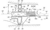
도 7은 카테터를 지나는 유체(예를 들어, 혈액)의 축방향 움직임을 조절/제어하기 위한 풍선, 및 풍선 팽창 동안 카테터 튜브 붕괴를 방지하도록 또한 기능하는 세퍼레이터를 가지는, 도 1의 선 2-2를 따라서 도시된 주입 팁의 대안적인 실시예 및 수축된 상태로 있는 풍선이 도시된 단면도;
도 8은 도 7의 주입 팁 및 팽창된 상태로 있는 풍선이 도시된 단면도;
도 9는 카테터를 지나는 유체(예를 들어, 혈액)의 축방향 움직임을 조절/제어하기 위한 풍선, 및 풍선 팽창 동안 카테터 튜브 붕괴를 방지하도록 또한 기능하는 고리 형상 링을 가지는, 도 1의 선 2-2를 따라서 도시된 주입 팁의 대안적인 실시예 및 수축된 상태로 있는 풍선이 도시된 단면도;
도 10은 도 9에 도시된 주입 팁 및 팽창된 상태로 있는 풍선이 도시된 단면도;
도 10a는 선 10A-10A을 따라서 도시된 도 9의 주입 팁 실시예의 단면도; 및
도 10b는 카테터의 중앙 루멘 내에 있는 팽창 튜브와 주입 튜브를 가지는 또 다른 주입 팁 실시예를 도시하는 도 10a에서와 같은 단면도.The invention itself, as well as novel features thereof, both as to its structure and its operation, will be best understood from the accompanying drawings, taken in conjunction with the accompanying description, in which like reference numerals refer to like parts,
1 is a schematic perspective view of a system of the present invention in which a system catheter positioned in an operating environment is shown;
Figure 2 is a cross-sectional view of the distal portion of the separator and system catheter shown along line 2-2 of Figure 1;
3 is a cross-sectional view of an alternate embodiment of the injection tip shown along line 2-2 of FIG. 1;
Figure 4 is a cross-sectional view of an alternative embodiment of the injection tip shown in Figure 3;
Figure 5a is a top view of a catheter positioned in a balloon and operating environment of the present invention in a contracted configuration;
FIG. 5B is a top view of a system catheter positioned in an inflated configuration of the balloon and operating environment of the present invention; FIG.
6 is a top view of an intravenous catheter for the present invention;
Fig. 7 is a cross-sectional view taken along line 2-2 of Fig. 1, with a balloon for controlling / controlling axial movement of fluid (e.g., blood) past the catheter, and a separator also functioning to prevent catheter tube collapse during balloon inflation An alternate embodiment of the injection tip shown along with a cross-sectional view of the balloon in its contracted state;
Figure 8 is a cross-sectional view of the infusion tip and inflated balloon of Figure 7;
FIG. 9 is a cross-sectional view taken along line 2 (FIG. 1) of FIG. 1 with a balloon for controlling / controlling the axial movement of fluid (e.g., blood) past the catheter and an annular ring that also serves to prevent catheter tube collapse during balloon inflation. An alternative embodiment of the injection tip shown in FIG. 2 and a cross-sectional view in which the balloon in the contracted state is shown;
10 is a cross-sectional view of the infusion tip and inflated balloon shown in FIG. 9;
10A is a cross-sectional view of the injection tip embodiment of FIG. 9 shown along
10B is a cross-sectional view as in FIG. 10A showing another injection tip embodiment having an inflation tube and infusion tube within the central lumen of the catheter.
먼저 도 1을 참조하여, 본 발명에 따라서 유체를 도입(주입)하기 위한 시스템이 도시되고 대체로 도면부호 10으로 지시된다. 도시된 바와 같이, 시스템(10)은 환자(도시되지 않음)의 혈관계에 있는 사전 결정된 위치에 카테터(10)를 위치시키도록 혈관(14) 내로 전진될 수 있는 카테터(12)를 포함한다. 본 발명의 목적을 위하여, 혈관(14)은 바람직하게 환자의 심장 혈관 시스템에 있는 동맥 또는 정맥이며, 시스템(10)은 동맥내, 정맥내 또는 관상동맥내 프로토콜을 위하여 사용된다.Referring first to Figure 1, a system for introducing (injecting) fluids in accordance with the present invention is shown and generally designated 10. As shown, the
상세하게, 도 1은 유체 매체(18)를 유지하기 위한 소스(16)를 포함한다. 또한 도 1에 도시된 바와 같이, 다수의 입자들은 입자/유체 매체(22)를 생성하도록 유체 매체(18)에서 현탁된다. 본 발명을 위하여, 입자(20)들은 약제의 일부 형태일 수 있거나, 또는 필시 생물학적 치료제(즉, 세포, 유전자 또는 단백질)의 일부 형태일 수 있다. 어떠한 경우에도, 입자(20)들은 소스(16)로부터 시스템(10)을 통해 혈관(14) 내로 운반을 위해 입자/유체 매체(22)에 현탁될 것이다. 시스템(10)에 대하여 상기된 바와 같이, 소스(16)는 당업계에 널리 공지된 형태의 주사기일 수 있다. 도 1은 또한, 시스템(10)이 소스(16)와 유체 연통하는 컨트롤러(24)를 포함한다는 것을 도시한다. 본 발명에 대해 예상되는 바와 같이, 컨트롤러(24)는 유체 유동 시스템(예를 들어, 시스템(10))을 통해 유체(예를 들어, 입자/유체 매체(22))를 움직이기 위하여 당업계에 공지된 임의의 형태의 디바이스일 수 있다. 일반적으로, 이러한 디바이스는 IV 펌프, 링거대, 주사기, 또는 다른 유체 유동 계량 장치일 수 있다. 소스(16)가 주사기인 시스템(10)의 실시예에 대하여, 컨트롤러(24)에 대한 특정의 필요성이 없다.In particular, Figure 1 includes a
도 1은 시스템(10)이 다음에 설명되는 바와 같은 목적을 위하여 팽창기(26)를 포함하는 것을 도시한다. 컨트롤러(24)와 팽창기(26)가 모두 시스템(10)을 위하여 사용될 때, 이것들은 카테터(12)와 별개의 유체 연통 채널을 각각 확립하도록 커넥터(28)에서 개별적으로 연결될 수 있다. 바람직하게, 도시된 바와 같이, 이러한 커넥터(28)는 카테터(12)의 근위 단부(30)와 유체 연통으로 연결된다.Figure 1 illustrates
도 1을 여전히 참조하여, 시스템(10)이 카테터(12)의 원위 단부(34)에 부착된 팁(필터)(32)(이후에 때때로 세퍼레이터(68)로서 또한 지칭된다)을 포함하는 것을 알 수 있다. 또한, 밸브(36)가 원위 단부(34)에 인접하여 카테터(12) 상에 장착되고, 그 구멍(38a 및 38b)들이 예시된 다수의 구멍들이 밸브(36)에 형성된 것을 알 수 있다. 카테터(12)의 원위 부분의 실제 구조, 및 세퍼레이터(68)와 밸브(36) 사이의 구조적 조화는 아마도 도 2를 참조하여 가장 잘 예측될 것이다.Still referring to FIG. 1, it can be seen that the
도 2를 참조하고, 세퍼레이터(68)에 대한 특정의 참조에 의해, 그 중 루멘(40a, 40b, 및 40c)이 예시된 다수의 루멘들이 세퍼레이터(68)에 형성된 것을 알 수 있을 것이다. 특히, 루멘들은 세퍼레이터(68)를 통해 축방향으로 연장하고, 서로 실질적으로 평행한다. 루멘들은 대체로 카테터(12)에 의해 한정된 축(42)에 실질적으로 평행하다. 중요하게, 각 루멘은 오직 개별적인 또는 작은 그룹의 입자(20)들을 수용하도록 특별히 치수화된 지름(44)이 확립된다. 비록 각 루멘이 한번에 몇개의 해교된 입자(20)들을 수용할 수 있을지라도, 개별적인 입자(20)들 또는 작은 그룹의 입자들은 입자들이 루멘(예를 들어, 루멘(40a) 참조)을 통과하는 동안 분리되어 유지된다. 또한, 세퍼레이터(68)는 혈관(14) 내에서 카테터(12)를 위치시키는 목적을 위하여 당업자에게 널리 공지된 방식으로 가이드 와이어(48)와 상호 작용하는 모노레일 루멘(46)이 형성될 수 있다.2, it will be appreciated that, by specific reference to the
염두에 둔 세퍼레이터(68)의 구조로, 상기된 바와 같이, 각 루멘의 지름(44)이 카테터(12)의 중앙 루멘(50)으로부터 루멘 내로 큰 그룹의 응집된 입자(20)들의 진입을 방지하도록 치수화된 것은 본 발명의 중요한 양태이다. 특히, 상이한 치료 프로토콜을 위하여, 입자(20)들이 혈관(14)에 들어감에 따라서 분산되고, 이에 의해, 세포가 관상동맥 순환 시스템 내로 주입되면 심근경색 또는 뇌졸증으로 이어질 수 있는 혈관(14)에서의 차후의 응집의 가능성을 최소화하는 것은 매우 필요할 수 있다. 또한, 입자들이 혈관(14)에 들어감에 따라서 입자(20)들의 분산은 조직에 대해 더욱 효율적인 분산을 위하여 혈액과의 보다 양호한 혼합을 제공할 것이다.The diameter of each
다수의 구멍들이 밸브(36)에 형성되었다는 것을 상기한다. 또한, 도 1 및 도 2를 교차 참조하여, 팽창될 때, 밸브(36)는 대체로 고리로서 형상화되고 팽창 챔버(52)가 형성되는 것이 또한 예측될 것이다. 도시된 바와 같이, 팽창 챔버(52)는 팽창 라인(54)을 통해 팽창기(26)와 유체 연통으로 연결된다. 이러한 구조 내에서, 팽창 라인(54)은 카테터(12) 내로 통합될 수 있다. 동작 목적을 위하여, 밸브(36)는 순응성 팽창 재료로 만들어진 밸브 바디(56)를 포함한다. 밸브(36)는, 고리 형상 밸브(36)의 주변에 위치되고 실질적으로 비순응성 재료로 만들어진 림(58)을 또한 포함한다. 시스템(10)을 위하여, 밸브(36)는 세퍼레이터(68)에 인접하여 위치되고, 아교 접착 또는 접착에 의한 것과 같이 당업계에서 널리 공지된 임의의 수단에 의해 카테터(12)의 외부면(60)에 부착된다.Recall that a plurality of holes are formed in the
동작적으로, 밸브(36)(풍선)는 수축된 구성으로부터 시작하고, 그런 다음 밸브(36)가 림(58)에 의해 구속되는 기본 구성(도 1 및 도 2 참조)으로 팽창기(26)에 의해 팽창된다. 이러한 기본 구성에서, 밸브(36)는 카테터(12)의 표면(60)으로부터 방사상 거리(62)를 통하여 연장하게 되고, 기본 구성에서, 아마도 혈관(14)과의 접촉을 만들 것이다. 또한, 기본 구성에서, 각 구멍(예를 들어, 구멍(38a))은 지름(64)을 가질 것이다. 팽창기(26)에 의한 밸브(36)의 추가의 팽창으로, 2개의 상이한 구조적 결과가 발생한다. 하나에 대하여, 림(58)은 기본 구성으로부터 확장하지 않는다. 그러므로, 방사상 거리(62)는 실질적으로 일정하게 유지된다. 다른 것에 대하여, 밸브 바디(56)는 구멍들이 증분적으로 조여지도록 팽창기(26)에 응답하여 확장할 것이다. 상이하게 설명된 바와 같이, 그리고 구멍(38a)에 대한 특정 참조로, 지름(64)은 축소될 것이다. 본 발명을 위한 대안적인 실시예에서, 밸브(36)에 대한 필요성이 없을 수 있다.1 and 2) in which the
동맥내, 정맥내 또는 관상동맥내 프로토콜에서 시스템(10)의 동작에 대하여, 가이드 와이어(48)가 환자의 혈관계에서 먼저 사전 위치된다. 가이드 와이어(48)는 그런 다음 카테터(12)의 모노레일 루멘(46) 내로 수용되고, 카테터(12)는 가이드 와이어(48) 위에서 환자의 혈관계에 있는 위치로 전진된다. 카테터(12)가 적절하게 위치되면, 밸브(36)는 그 기본 구성으로, 또는 그 이상으로 팽창된다. 밸브(36)를 위한 정확한 범위의 팽창은 혈관(14)에 있는 구멍들을 통한 유체의 필요한 유량에 의존할 것이다. 팽창된 밸브(36)에 의해, 컨트롤러(24)는 소스(16)로부터 카테터(12)의 중앙 루멘(50)을 통한 입자/유체 매체(22)의 유동을 유발하도록 활성화된다. 입자/유체 매체(22)에 있는 입자(20)들이 세퍼레이터(68)에 도달함에 따라서, 세퍼레이터(68)에 있는 개별 루멘들의 각각의 지름(44)은 단지 개별 입자(20)들 또는 작은 그룹의 입자(20)들만이 루멘에 들어가는 것을 가능하게 한다. 그러므로, 중앙 루멘(50)에서 입자(20)들의 응집은 분열되며, 입자들이 세퍼레이터(68)를 통과한 후에 입자(20)들의 응집은 최소화된다. 비록, 상기 설명이 환자의 심장 혈관 시스템 내에서 시스템(10)의 적용에 초점을 맞추었을지라도, 시스템(10)은 유체 유동(예를 들어, 혈관(14)을 통한 혈류) 내로 개별 입자(20)로서 추후 방출을 위하여 입자(20)들이 입자/유체 매체(22)에 현탁될 수 있는 임의의 사용에 적절하다.For operation of the
도 3을 참조하여, 생물학적 치료제를 위한 주입 팁이 도시되며, 대체로 도면부호 66으로 지시된다. 이 실시예에서, 세퍼레이터(68')는 카테터(12)의 원위 단부(34)로부터 거리(d)에서 카테터(12)의 중앙 루멘(50)에 위치된다. 이렇게 위치됨에 따라서, 세퍼레이터(68')는 카테터(12)의 원위 단부(34)에서 길이(d)를 가지는 재수집 챔버(70)를 생성한다. 특별히, 재수집 챔버(70)는 카테터(12)의 원위 단부(34) 상에 형성된 관형 섹션이다. 필요하면, 재수집 챔버(70)는 카테터(12)의 원위 단부(34)에 부착될 수 있는 관형의 독립 부분에 의해 확립될 수 있다.Referring to FIG. 3, an injection tip for a biological therapeutic agent is shown, generally indicated at 66. In this embodiment, a separator 68 'is positioned in the
여전히 도 3을 참조하여, 세퍼레이터(68')가 근위(상류) 표면(72)과 원위(하류) 표면(74)을 가지는 것을 알 수 있다. 상세하게, 세퍼레이터(68')의 근위 표면(72)은 카테터(12)의 축(42)에 대해 경사 각도(α)로 배향된다. 그러나, 세퍼레이터(68')의 원위 표면(74)은 축(42)에 직각이며, 실질적으로 평탄하다. 상기된 구조를 염두에 두면, 경사진 근위 표면(72)의 결과는 각 루멘(76a-c)의 근위 단부가 카테터(12)의 축(42)에 대해 각도(α)로 경사진다는 것이다. 결과적으로, 유체가 카테터(12)를 통해 유동하고 카테터(12)의 경사진 근위 표면(72)을 만날 때, 세퍼레이터(68')의 루멘(76a-c)을 통하여 유동하도록 방향이 바뀐다. 동작 시에, 이러한 방향 바꿈은 유체에 있는 입자(20)들이 환자의 혈관계에 들어가기 전에 응집하는 것을 방지하는데 도움이 된다. 세퍼레이터(68')의 루멘(76a-c)을 빠져나갈 때, 유체는 재수집 챔버(70)에 들어가고, 환자의 혈관계에 들어가기 전에 느리게 되는 것이 가능하게 된다.Still referring to FIG. 3, it can be seen that the separator 68 'has a proximal (upstream)
도 3 및 도 4에 도시된 실시예에 대하여, 가이드 와이어 출구 루멘(78)은 세퍼레이터(68' 및 68")에 인접한 대략 25-30㎜ 위치에서 카테터(12) 상에 형성된다.3 and 4, a guide
지금 도 4를 참조하여, 주입 팁(66')의 변형이 도시되며, 세퍼레이터(68")의 근위 표면(72)은 계단 구성이 형성된다. 계단 구성으로 인하여, 각 루멘(80a-c)의 근위 단부는 카테터(12)의 축(42)에 실질적으로 직각으로 유지된다. 그러므로, 모든 중요한 점에서, 도 3 및 도 4에 도시된 주입 팁(66, 66')들은 각각 근위 표면들이 다른 것 외에 동일하다. 세퍼레이터(68)의 근위 표면(72)이 세퍼레이터(32/68)에 대하여 도 2에 도시된 형상을 또한 취할 수 있다는 것을 유념하여야 한다.Referring now to Figure 4, a deformation of the injection tip 66 'is shown and a
도 5a 및 도 5b를 지금 참조하여, 도시된 선택적으로 팽창 가능한 풍선(82)은 세퍼레이터(68)에 인접한 위치에서 카테터(12)에 부착된다. 도 5b에 도시된 바와 같이 팽창될 때, 풍선(82')은 혈관벽(84)을 향하여 카테터(12)로부터 방사상으로 멀리 확장하는 것에 의해 카테터(12) 주위의 혈액의 유량을 제어한다. 본 발명에 대해 예상되는 바와 같이, 카테터(12) 외부에서 혈액의 유량은 카테터(12)의 원위 표면(34)에서 난류를 최소화하기 위하여 카테터(12) 내부의 유체의 유량과 비교 가능하여야 한다. 어떤 경우에, 재수집 챔버(70) 및 팽창성 풍선(82)의 전반적인 목적은, 입자 추가 시간을 분산시키고 혈관을 통해 치료될 조직 내로 진행하도록 혈액의 유량을 감소시키는 것을 가능하게 하는 것에 의해 주입 동안 환자의 혈관에 대한 손상 및 상해의 가능성을 감소시키는 것이다.Referring now to Figures 5A and 5B, the selectively
도 6을 지금 참조하여, 본 발명에 따른 주입 팁(66)이 당업계에 널리 공지된 형태의 정맥 카테터(86)에서 이용될 수 있다는 것이 또한 예측되어야 한다. 정맥 카테터(86)가 사용되면, 주입 팁(66)은 본질적으로 다른 실시예에 대하여 상기된 바와 동일할 것이다. 여기에서 이점은, 적절한 상황에서, 정맥 카테터(86)가 유체 소스(16)로부터 유체의 방출 전에 환자에 고정될 수 있다는 것이다. 예를 들어, 날개(90a-b)들은 유체 소스(16)로부터 유체(18)의 방출 전에 환자에게 고정된다. 모든 다른 중요한 점에서, 본 발명의 주입 팁(66)을 구비한 정맥 카테터(86)의 동작은 이전에 설명된 동작과 동일하다.With reference now to Figure 6, it should also be expected that the
도 7은 내부면(94)과 외부면(96)을 구비한 관형상 벽(92)을 갖는 세장형 카테터(12')를 가지는 주입 팁(66")의 또 다른 실시예를 도시한다. 도시된 바와 같이, 벽(92)의 내부면(94)은 카테터(12')를 위한 중앙 루멘(50')을 둘러싼다. 도 7은 팽창성 풍선(82")이 외벽(96) 상에 장착된 것을 도시한다. 팽창 루멘(98)은 풍선(82")(도 8에 도시된 팽창된 풍선(82"))을 선택적으로 팽창시키도록 제공된다. 외벽(96)의 일부가 팽창 챔버(100)를 확립하도록 풍선(82")과 협동하는 것을 알 수 있다. 풍선(82")을 팽창시키도록, 팽창 유체는 팽창 챔버(100)에서 사전 선택된 팽창 압력을 확립하도록 예를 들어 도 1에 도시되고 상기된 팽창기(26)를 사용하여 팽창 루멘(98)을 통해 펌핑된다. 이러한 압력이 방사상으로 내향하고 카테터(12')를 수축 또는 붕괴하려는, 벽(92) 상의 힘을 확립할 것이라는 것이 예측된다. 상기된 바와 같이, 카테터(12')의 붕괴 또는 수축은 중앙 루멘에서의 유동을 불필요하게 방해하고 및/또는 중앙 루멘 유동에서의 줄기세포와 같은 세포에 응력을 주어, 세포 생존성을 낮춘다(때때로 70-80%까지).Figure 7 shows another embodiment of an
이러한 붕괴를 방지하도록, 도 7은 주입 팁(66")이 팽창성 풍선(82") 아래에서 카테터 벽(92)을 지지하도록 보강 부재(102)를 포함할 수 있는 것을 도시한다. 도시된 바와 같이, 도 7의 실시예에 따라서, 보강 부재(102)는 풍선(82") 아래에서 중앙 루멘(50')에 위치되는 세퍼레이터(68')(도 3을 참조하여 상기된 바와 같은)이다. 대안적으로, 도 2에 도시된 세퍼레이터(32/68), 도 4에 도시된 세퍼레이터(68"), 또는 유사한 세퍼레이터는 풍선(82")의 팽창 동안 벽(92)을 보강하도록 풍선(82") 아래에 있는 중앙 루멘(50')에 위치될 수 있다. 기능적으로, 보강 부재(102)는 벽(92)의 붕괴를 방지하며, 풍선(82")의 팽창 동안 중앙 루멘(50')에 대하여 실질적으로 일정한 단면을 유지하며, 주입 동안 중앙 루멘(50')을 통과하도록 방해받지 않은 유체 유동을 허용한다.To prevent this collapse, Figure 7 illustrates that the
도 7 및 도 8에 도시된 배열에 의해, 주입 팁(66")은 풍선(82")이 수축된 상태(도 7에 도시된 바와 같은)에서 입자(20)들의 전달에 적합한 치료 위치로 전진될 수 있다. 다음에, 치료 부위에서 주입 팁(66")으로, 풍선(82")은 주입 팁(66")을 지나서 유동하는 혈액에 대하여 혈관계에서 혈액의 유동을 제어 및/또는 조절하도록 선택적으로 팽창된다(도 8에 도시된 바와 같이). 혈류(도시되지 않음)가 적절하게 조절되었으면, 입자(20)들을 포함하는 입자/유체 매체(22)는 중앙 루멘(50')으로 도입되고, 크고 응집된 입자들이 혈류에 들어가는 것을 방지하도록 세퍼레이터(68')를 통과할 수 있다. 입자/유체 매체(22)는 그런 다음 재수집 챔버(70')를 통과하여 카테터(12')의 원위 단부(34')를 빠져나간다. 주입 후에, 풍선(82")은 수축될 수 있으며, 주입 팁(66")은 환자의 혈관계로부터 빼내진다.7 and 8, the
도 9, 도 10 및 도 10a는 내부면(94')과 외부면(96')을 구비한 관형상 벽(92')(도 9 참조)을 가지는 세장형 카테터(12")를 위한 주입 팁(66"')의 또 다른 실시예를 도시한다. 도시된 바와 같이, 벽(92')의 내부면(94')은 카테터(12")를 위한 중앙 루멘(50")을 둘러싼다. 도 7은 팽창성 풍선(82"')이 외벽(96') 상에 장착된 것을 또한 도시한다. 팽창 루멘(98')은 풍선(82"')(도 10에 도시된 팽창된 풍선(82"'))을 선택적으로 팽창시키도록 제공된다. 외벽(96')의 일부가 팽창 챔버(100')를 확립하도록 풍선(82"')과 협동하는 것을 알 수 있다. 풍선(82"')을 팽창시키도록, 팽창 유체는 예를 들어 팽창 챔버(100')에서 사전 선택된 팽창 압력을 확립하도록 도 1에 도시되고 설명된 팽창기(26)를 사용하여 팽창 루멘(98')을 통해 펌핑된다. 이러한 압력이 방사상으로 내향하고 카테터(12")를 수축 또는 붕괴하려는, 벽(92') 상의 힘을 확립할 것이라는 것이 예측된다. 상기된 바와 같이, 카테터(12")의 붕괴 또는 수축은 중앙 루멘에서의 유동을 불필요하게 방해하고 및/또는 중앙 루멘 유동에서의 줄기세포와 같은 세포에 응력을 주어, 세포 생존성을 낮춘다(때때로 70-80%까지).Figures 9,10 and 10a illustrate an injection tip for an
이러한 붕괴를 방지하도록, 도 9는 주입 팁(66")이 팽창성 풍선(82'") 아래에서 카테터 벽(92')을 지지하도록 보강 부재(102')를 포함할 수 있는 것을 도시한다. 도시된 바와 같이, 도 9의 실시예에 따라서, 보강 부재(102')는 풍선(82'") 아래에서 카테터 벽(94')의 외부면(96')에 부착된 고리 형상 링으로서 형성된다. 부착되면, 링 형상 보강 부재(102')는 도시된 바와 같이 주입 카테터(12")에 의해 한정된 길이방향 축(42')에 실질적으로 직각으로 배향된다. 기능적으로, 보강 부재(102')는 벽(92')의 붕괴를 방지하며, 풍선(82"')의 팽창 동안 중앙 루멘(50")에 대하여 실질적으로 일정한 단면을 유지하며, 주입 동안 중앙 루멘(50")을 통과하도록 방해받지 않은 유체 유동을 허용한다.To prevent this collapse, FIG. 9 illustrates that the injection tip 66 '' may include a reinforcing member 102 'to support the catheter wall 92' below the inflatable balloon 82 ''. As shown, according to the embodiment of FIG. 9, a reinforcing member 102 'is formed as an annular ring attached to the outer surface 96' of the catheter wall 94 'below the balloon 82' '' The annular reinforcing member 102 'is oriented at a substantially right angle to the longitudinal axis 42' defined by the
도 9 및 도 10에 도시된 배열에 의해, 주입 팁(66'")은 수축된 상태(도 9에 도시된 바와 같은)에서 풍선(82'")과 함께 입자(20)들의 전달에 적합한 치료 위치로 전진될 수 있다. 다음에, 치료 부위에서 주입 팁(66"')으로, 풍선(82"')은 주입 팁(66'")을 지나서 유동하는 혈액에 대하여 혈관계에서 혈액의 유동을 제어 및/또는 조절하도록 선택적으로 팽창된다(도 10에 도시된 바와 같이). 혈류(도시되지 않음)가 적절하게 조절되었으면, 입자(20)들을 포함하는 입자/유체 매체(22)는 중앙 루멘(50")으로 도입되고, 크고 응집된 입자들이 혈류에 들어가는 것을 방지하도록 세퍼레이터(68')를 통과할 수 있다. 대안적으로, 도 2에 도시된 세퍼레이터(32/68), 도 4에 도시된 세퍼레이터(68"), 또는 유사한 세러페이터가 사용될 수 있다. 입자/유체 매체(22)는 그런 다음 재수집 챔버(70")를 통과하여 카테터(12")의 원위 단부(34")를 빠져나간다. 주입 후에, 풍선(82'")은 수축될 수 있으며, 주입 팁(66"')은 환자의 혈관계로부터 빼내진다.With the arrangement shown in Figures 9 and 10, the
도 10b는 카테터(12"')의 중앙 루멘(50"') 내에 위치된 팽창 튜브(104)와 주입 튜브(106)를 가지는 또 다른 주입 팁 실시예를 도시한다. 이 실시예에 대하여, 팽창성 풍선(82"")은 카테터(12"') 상에 장착되고, 팽창성 풍선(82"")과 유체 연통으로 연결된다. 풍선(82"")의 팽창 동안 카테터(12"')의 붕괴를 방지하도록, 보강 부재(102")는 카테터(12"')를 지지하도록 제공된다. 팽창 동안 카테터(12"')의 붕괴는 주입 튜브(106)를 수축시키고, 불필요하게 주입 튜브(106)에서 유동을 방해하고 및/또는 주입 튜브(106)에 있는 줄기세포와 같은 세포에 응력을 주어 세포 생존성을 낮춘다. 도시된 바와 같이, 도 10b의 실시예에 대하여, 보강 부재(102")는 풍선(82"") 아래에서 카테터(12"')의 외부면에 부착된 고리 형상 링으로서 형성될 수 있다.Figure 10B shows another injection tip embodiment having an
본 명세서에 상세하게 도시되고 설명된 보강된 외부 풍선 밸브를 구비한 생물학적 치료제를 위한 특정 주입 카테터 팁이 전체적으로 앞에서 설명된 목적을 달성하고 이점을 제공할 수 있지만, 본 발명의 바람직한 실시예들의 단지 예시이며, 첨부된 청구항들에 설명된 바와 달리 도시된 구성 또는 설계의 상세에 대해 어떠한 제한도 의도되지 않는다는 것이 이해되어야 한다.Although specific infusion catheter tips for biologic therapy with a reinforced external balloon valve shown and described in detail herein may achieve the objectives described above and provide advantages, it should be understood that only a few examples of preferred embodiments of the present invention And that no limitations are intended to the details of the construction or design shown, other than as described in the appended claims.
Claims (20)
Translated fromKorean내부면과 외부면을 구비한 관형상 벽을 가지는 세장형 카테터로서, 상기 벽의 내부면이 상기 카테터의 근위 단부와 원위 단부 사이에서 연장하는 중앙 루멘을 한정하는, 상기 세장형 카테터;
상기 카테터 벽의 외부면 상에 장착되는 팽창성 풍선;
상기 카테터를 지나는 혈관계에서의 혈액의 유동을 제어하고 조절하도록 상기 풍선을 선택적으로 팽창시키기 위하여 상기 풍선과 유체 연통으로 연결되는 팽창기; 및
상기 중앙 루멘의 일부를 둘러싸는 상기 카테터 벽의 섹션과 접촉하도록 위치되는 보강 부재를 포함하며,
상기 보강 부재는, 상기 카테터 벽을 강화하고 상기 풍선의 팽창 동안 상기 중앙 루멘에 대하여 실질적으로 일정한 단면을 유지하도록, 상기 팽창성 풍선 아래에 위치되는 시스템.A system for injecting stem cells into a patient at a predetermined site in the vascular system,
A elongated catheter having a tubular wall having an inner surface and an outer surface, wherein the inner surface of the wall defines a central lumen extending between a proximal end and a distal end of the catheter;
An inflatable balloon mounted on an exterior surface of the catheter wall;
An inflator in fluid communication with the balloon for selectively inflating the balloon to control and regulate the flow of blood through the catheter; And
And a reinforcing member positioned to contact a section of the catheter wall surrounding a portion of the central lumen,
Wherein the stiffening member is positioned beneath the inflatable balloon to reinforce the catheter wall and maintain a substantially constant cross-section relative to the central lumen during inflation of the balloon.
근위 단부와 원위 단부 사이에서 연장하는 중앙 루멘이 형성되고, 축을 한정하는 세장형 카테터;
유체에서 현탁된 상기 입자들의 소스로서, 상기 카테터의 근위 단부와 유체 연통으로 연결되는 상기 소스;
상기 입자 소스와 유체 연통하며, 근위 단부 및 원위 단부를 가지며, 다수의 길이방향으로 정렬된 병렬 루멘들이 형성되며, 각 루멘은 통과하는 입자들을 수용하도록 치수화되는, 실질적으로 원통형으로 형상화된 세퍼레이터;
상기 카테터 주위에 위치되어 상기 카테터에 부착되며, 상기 축에 대해 실질적으로 평행한 방향으로, 상기 카테터 주위에서 혈류를 제어하도록 상기 카테터로부터 외향하는 방사상 방향으로 연장 가능한 팽창성 풍선;
상기 중앙 루멘의 일부를 둘러싸는 상기 카테터 벽의 섹션과 접촉하도록 위치되고, 상기 카테터 벽을 강화하고 상기 풍선의 팽창 동안 상기 중앙 루멘에 대하여 실질적으로 일정한 단면을 유지하도록 상기 팽창성 풍선 아래에 위치되는 보강 부재;
상기 소스로부터 상기 세퍼레이터를 통하여 환자의 혈관계 내로 입자들을 움직이기 위한 주입 디바이스; 및
기본 구성으로부터 2차 구성으로 상기 풍선을 선택적으로 구성하기 위한 팽창기를 포함하며,
상기 풍선은 상기 기본 구성에서 수축되고, 상기 2차 구성에서 팽창되는 시스템.A system for introducing particles into a vascular system of a patient,
A elongated catheter defining a central lumen extending between a proximal end and a distal end and defining an axis;
A source in fluid communication with a proximal end of the catheter, the source of the particles suspended in a fluid;
A substantially cylindrical shaped separator in fluid communication with the particle source and having a proximal end and a distal end, wherein a plurality of longitudinally aligned parallel lumens are formed, each lumen sized to receive particles passing therethrough;
An inflatable balloon positioned about the catheter and attached to the catheter and extending in a radially direction outwardly from the catheter to control blood flow around the catheter, in a direction substantially parallel to the axis;
A catheter wall positioned to contact a section of the catheter wall surrounding a portion of the central lumen and configured to reinforce the catheter wall and to provide a reinforcement positioned under the inflatable balloon to maintain a substantially constant cross-section relative to the central lumen during inflation of the balloon absence;
An injection device for moving particles from the source through the separator into a vascular system of a patient; And
And an inflator for selectively configuring the balloon from a basic configuration to a secondary configuration,
Wherein the balloon is deflated in the basic configuration and inflated in the secondary configuration.
내부면과 외부면을 구비한 관형상 벽을 가지는 세장형 카테터를 제공하는 단계로서, 상기 벽의 내부면은 상기 카테터의 근위 단부와 원위 단부 사이에서 연장하는 중앙 루멘을 한정하는, 상기 단계;
상기 카테터 벽의 외부면 상에 팽창성 풍선을 장착하는 단계;
상기 풍선과 유체 연통으로 팽창기를 연결하는 단계;
상기 중앙 루멘의 일부를 둘러싸는 상기 카테터 벽의 섹션과 접촉하도록 보강 부재를 위치시키는 단계로서, 상기 보강 부재는 상기 카테터 벽을 강화하고 상기 풍선의 팽창 동안 상기 중앙 루멘에 대하여 실질적으로 일정한 단면을 유지하도록 상기 팽창성 풍선 아래에 위치되는, 상기 상기 보강 부재를 위치시키는 단계;
상기 카테터를 지나는 혈관계에서의 혈액의 유동을 제어하고 조절하도록 상기 풍선을 선택적으로 팽창시키는 단계; 및
소스로부터 상기 중앙 루멘을 통하여 환자의 혈관계 내로 입자들을 움직이도록 주입 디바이스를 사용하는 단계를 포함하는 방법.CLAIMS 1. A method for introducing particles into a vascular system of a patient,
Providing a elongated catheter having a tubular wall having an inner surface and an outer surface, the inner surface of the wall defining a central lumen extending between a proximal end and a distal end of the catheter;
Mounting an inflatable balloon on the exterior surface of the catheter wall;
Coupling the inflator with the balloon in fluid communication;
Positioning a stiffening member in contact with a section of the catheter wall surrounding a portion of the central lumen, the stiffening member maintaining a substantially constant cross-section with respect to the central lumen during inflation of the balloon, Said inflatable balloon being positioned below said inflatable balloon;
Selectively inflating the balloon to control and regulate the flow of blood through the vascular system across the catheter; And
Using an injection device to move particles from the source through the central lumen into the vascular system of the patient.
Applications Claiming Priority (3)
| Application Number | Priority Date | Filing Date | Title |
|---|---|---|---|
| US14/145,158US10058675B2 (en) | 2009-09-21 | 2013-12-31 | Infusion catheter tip for biologics with reinforced external balloon valve |
| US14/145,158 | 2013-12-31 | ||
| PCT/US2014/069253WO2015102820A2 (en) | 2013-12-31 | 2014-12-09 | Infusion catheter tip for biologics with reinforced external balloon valve |
Publications (1)
| Publication Number | Publication Date |
|---|---|
| KR20160105829Atrue KR20160105829A (en) | 2016-09-07 |
Family
ID=53494210
Family Applications (1)
| Application Number | Title | Priority Date | Filing Date |
|---|---|---|---|
| KR1020167020515ACeasedKR20160105829A (en) | 2013-12-31 | 2014-12-09 | Infusion catheter tip for biologics with reinforced external balloon valve |
Country Status (10)
| Country | Link |
|---|---|
| EP (1) | EP3089779B1 (en) |
| JP (1) | JP2017502770A (en) |
| KR (1) | KR20160105829A (en) |
| CN (1) | CN106029154B (en) |
| AU (1) | AU2014374253B2 (en) |
| BR (1) | BR112016015361A2 (en) |
| CA (1) | CA2934880A1 (en) |
| IL (1) | IL246519A0 (en) |
| SG (1) | SG11201605320VA (en) |
| WO (1) | WO2015102820A2 (en) |
Cited By (1)
| Publication number | Priority date | Publication date | Assignee | Title |
|---|---|---|---|---|
| WO2022154138A1 (en)* | 2021-01-13 | 2022-07-21 | (주)앰틱스바이오 | Device for spraying wound dressing material for peptic ulcer |
Families Citing this family (4)
| Publication number | Priority date | Publication date | Assignee | Title |
|---|---|---|---|---|
| US10155099B2 (en) | 2009-09-21 | 2018-12-18 | Cook Regentec Llc | Method for infusing stem cells |
| US10058675B2 (en) | 2009-09-21 | 2018-08-28 | Cook Regentec Llc | Infusion catheter tip for biologics with reinforced external balloon valve |
| SG11202107233VA (en)* | 2019-01-09 | 2021-07-29 | Vena Medical Holdings Corp | Cerebrovascular pathology viewing and treatment apparatus |
| US11517867B2 (en)* | 2019-02-08 | 2022-12-06 | Air Liquide Large Industries U.S. Lp | Apparatus for installing a thermocouple inside a reactor tube filled with catalyst |
Family Cites Families (15)
| Publication number | Priority date | Publication date | Assignee | Title |
|---|---|---|---|---|
| IN171253B (en)* | 1986-11-04 | 1992-08-22 | Bard Inc C R | |
| JPH01145074A (en)* | 1987-12-01 | 1989-06-07 | Terumo Corp | Balloon catheter |
| JP3744571B2 (en)* | 1995-09-06 | 2006-02-15 | 株式会社ヴァーユ | Perfusion catheter |
| US5989218A (en)* | 1997-11-18 | 1999-11-23 | Advanced Cardiovascular Systems, Inc. | Perfusion catheter with coil supported inner tubular member |
| US6048332A (en)* | 1998-10-09 | 2000-04-11 | Ave Connaught | Dimpled porous infusion balloon |
| US6663613B1 (en)* | 2000-01-25 | 2003-12-16 | Bacchus Vascular, Inc. | System and methods for clot dissolution |
| US9242069B2 (en)* | 2001-09-30 | 2016-01-26 | Scicotec Gmbh | Method for control of stem cell injection into the body |
| US20070003528A1 (en)* | 2005-06-29 | 2007-01-04 | Paul Consigny | Intracoronary device and method of use thereof |
| US7713232B2 (en)* | 2005-11-04 | 2010-05-11 | Medrad, Inc. | System for washing and processing of cells for delivery thereof to tissue |
| US20100004593A1 (en)* | 2006-09-13 | 2010-01-07 | Boston Scientific Scimed, Inc. | Balloon catheter |
| DE102009017033A1 (en)* | 2009-04-09 | 2010-10-21 | Pulsion Medical Systems Ag | Bladder catheter for measuring the pressure in the bladder of a living being |
| US8790298B2 (en)* | 2009-09-21 | 2014-07-29 | Translational Biologic Infusion Catheter, Llc | Infusion catheter tip for biologics |
| US9050414B2 (en)* | 2010-02-19 | 2015-06-09 | Cardiovascular Systems, Inc. | Systems and methods for mixing therapeutic agents before and/or during administration |
| JP2011244905A (en)* | 2010-05-25 | 2011-12-08 | Asahi Intecc Co Ltd | Balloon catheter |
| SG11201407429PA (en)* | 2012-05-17 | 2014-12-30 | Translational Biolog Infusion Catheter Llc | Infusion catheter tip for biologics |
- 2014
- 2014-12-09KRKR1020167020515Apatent/KR20160105829A/ennot_activeCeased
- 2014-12-09AUAU2014374253Apatent/AU2014374253B2/enactiveActive
- 2014-12-09CACA2934880Apatent/CA2934880A1/ennot_activeAbandoned
- 2014-12-09SGSG11201605320VApatent/SG11201605320VA/enunknown
- 2014-12-09WOPCT/US2014/069253patent/WO2015102820A2/enactiveApplication Filing
- 2014-12-09EPEP14877016.7Apatent/EP3089779B1/enactiveActive
- 2014-12-09BRBR112016015361Apatent/BR112016015361A2/ennot_activeIP Right Cessation
- 2014-12-09JPJP2016544602Apatent/JP2017502770A/enactivePending
- 2014-12-09CNCN201480073983.XApatent/CN106029154B/enactiveActive
- 2016
- 2016-06-28ILIL246519Apatent/IL246519A0/enunknown
Cited By (1)
| Publication number | Priority date | Publication date | Assignee | Title |
|---|---|---|---|---|
| WO2022154138A1 (en)* | 2021-01-13 | 2022-07-21 | (주)앰틱스바이오 | Device for spraying wound dressing material for peptic ulcer |
Also Published As
| Publication number | Publication date |
|---|---|
| AU2014374253B2 (en) | 2020-01-23 |
| CN106029154B (en) | 2020-06-16 |
| SG11201605320VA (en) | 2016-07-28 |
| AU2014374253A1 (en) | 2016-08-04 |
| EP3089779A2 (en) | 2016-11-09 |
| IL246519A0 (en) | 2016-08-31 |
| WO2015102820A3 (en) | 2015-11-19 |
| CA2934880A1 (en) | 2015-07-09 |
| WO2015102820A2 (en) | 2015-07-09 |
| EP3089779A4 (en) | 2017-08-30 |
| JP2017502770A (en) | 2017-01-26 |
| CN106029154A (en) | 2016-10-12 |
| BR112016015361A2 (en) | 2017-08-08 |
| EP3089779B1 (en) | 2019-10-16 |
Similar Documents
| Publication | Publication Date | Title |
|---|---|---|
| US10058675B2 (en) | Infusion catheter tip for biologics with reinforced external balloon valve | |
| KR101803861B1 (en) | Biologics infusion system | |
| KR20160105829A (en) | Infusion catheter tip for biologics with reinforced external balloon valve | |
| US20210031002A1 (en) | Method for infusing stem cells | |
| JP6352903B2 (en) | Infusion catheter tip for biologics | |
| US8790298B2 (en) | Infusion catheter tip for biologics | |
| JP2017502770A5 (en) | ||
| AU2015225718B2 (en) | Method for infusing stem cells | |
| HK1224974B (en) | Infusion catheter tip for biologics with reinforced external balloon valve | |
| HK1224974A1 (en) | Infusion catheter tip for biologics with reinforced external balloon valve | |
| US20200179643A1 (en) | Catheter for Atraumatic Fluid Delivery |
Legal Events
| Date | Code | Title | Description |
|---|---|---|---|
| PA0105 | International application | Patent event date:20160727 Patent event code:PA01051R01D Comment text:International Patent Application | |
| PG1501 | Laying open of application | ||
| A201 | Request for examination | ||
| PA0201 | Request for examination | Patent event code:PA02012R01D Patent event date:20191209 Comment text:Request for Examination of Application | |
| E902 | Notification of reason for refusal | ||
| PE0902 | Notice of grounds for rejection | Comment text:Notification of reason for refusal Patent event date:20210831 Patent event code:PE09021S01D | |
| E601 | Decision to refuse application | ||
| PE0601 | Decision on rejection of patent | Patent event date:20211126 Comment text:Decision to Refuse Application Patent event code:PE06012S01D Patent event date:20210831 Comment text:Notification of reason for refusal Patent event code:PE06011S01I |