KR20160103150A - Flexible helical stent having intermediated non-helical region - Google Patents
Flexible helical stent having intermediated non-helical regionDownload PDFInfo
- Publication number
- KR20160103150A KR20160103150AKR1020167022605AKR20167022605AKR20160103150AKR 20160103150 AKR20160103150 AKR 20160103150AKR 1020167022605 AKR1020167022605 AKR 1020167022605AKR 20167022605 AKR20167022605 AKR 20167022605AKR 20160103150 AKR20160103150 AKR 20160103150A
- Authority
- KR
- South Korea
- Prior art keywords
- stent
- strut
- flexible
- section
- struts
- Prior art date
- Legal status (The legal status is an assumption and is not a legal conclusion. Google has not performed a legal analysis and makes no representation as to the accuracy of the status listed.)
- Granted
Links
Images


Classifications
- A—HUMAN NECESSITIES
- A61—MEDICAL OR VETERINARY SCIENCE; HYGIENE
- A61F—FILTERS IMPLANTABLE INTO BLOOD VESSELS; PROSTHESES; DEVICES PROVIDING PATENCY TO, OR PREVENTING COLLAPSING OF, TUBULAR STRUCTURES OF THE BODY, e.g. STENTS; ORTHOPAEDIC, NURSING OR CONTRACEPTIVE DEVICES; FOMENTATION; TREATMENT OR PROTECTION OF EYES OR EARS; BANDAGES, DRESSINGS OR ABSORBENT PADS; FIRST-AID KITS
- A61F2/00—Filters implantable into blood vessels; Prostheses, i.e. artificial substitutes or replacements for parts of the body; Appliances for connecting them with the body; Devices providing patency to, or preventing collapsing of, tubular structures of the body, e.g. stents
- A61F2/82—Devices providing patency to, or preventing collapsing of, tubular structures of the body, e.g. stents
- A61F2/86—Stents in a form characterised by the wire-like elements; Stents in the form characterised by a net-like or mesh-like structure
- A61F2/88—Stents in a form characterised by the wire-like elements; Stents in the form characterised by a net-like or mesh-like structure the wire-like elements formed as helical or spiral coils
- A—HUMAN NECESSITIES
- A61—MEDICAL OR VETERINARY SCIENCE; HYGIENE
- A61F—FILTERS IMPLANTABLE INTO BLOOD VESSELS; PROSTHESES; DEVICES PROVIDING PATENCY TO, OR PREVENTING COLLAPSING OF, TUBULAR STRUCTURES OF THE BODY, e.g. STENTS; ORTHOPAEDIC, NURSING OR CONTRACEPTIVE DEVICES; FOMENTATION; TREATMENT OR PROTECTION OF EYES OR EARS; BANDAGES, DRESSINGS OR ABSORBENT PADS; FIRST-AID KITS
- A61F2/00—Filters implantable into blood vessels; Prostheses, i.e. artificial substitutes or replacements for parts of the body; Appliances for connecting them with the body; Devices providing patency to, or preventing collapsing of, tubular structures of the body, e.g. stents
- A61F2/82—Devices providing patency to, or preventing collapsing of, tubular structures of the body, e.g. stents
- A61F2/86—Stents in a form characterised by the wire-like elements; Stents in the form characterised by a net-like or mesh-like structure
- A61F2/90—Stents in a form characterised by the wire-like elements; Stents in the form characterised by a net-like or mesh-like structure characterised by a net-like or mesh-like structure
- A61F2/91—Stents in a form characterised by the wire-like elements; Stents in the form characterised by a net-like or mesh-like structure characterised by a net-like or mesh-like structure made from perforated sheets or tubes, e.g. perforated by laser cuts or etched holes
- A61F2/915—Stents in a form characterised by the wire-like elements; Stents in the form characterised by a net-like or mesh-like structure characterised by a net-like or mesh-like structure made from perforated sheets or tubes, e.g. perforated by laser cuts or etched holes with bands having a meander structure, adjacent bands being connected to each other
- A61F2002/91508—Stents in a form characterised by the wire-like elements; Stents in the form characterised by a net-like or mesh-like structure characterised by a net-like or mesh-like structure made from perforated sheets or tubes, e.g. perforated by laser cuts or etched holes with bands having a meander structure, adjacent bands being connected to each other the meander having a difference in amplitude along the band
- A—HUMAN NECESSITIES
- A61—MEDICAL OR VETERINARY SCIENCE; HYGIENE
- A61F—FILTERS IMPLANTABLE INTO BLOOD VESSELS; PROSTHESES; DEVICES PROVIDING PATENCY TO, OR PREVENTING COLLAPSING OF, TUBULAR STRUCTURES OF THE BODY, e.g. STENTS; ORTHOPAEDIC, NURSING OR CONTRACEPTIVE DEVICES; FOMENTATION; TREATMENT OR PROTECTION OF EYES OR EARS; BANDAGES, DRESSINGS OR ABSORBENT PADS; FIRST-AID KITS
- A61F2/00—Filters implantable into blood vessels; Prostheses, i.e. artificial substitutes or replacements for parts of the body; Appliances for connecting them with the body; Devices providing patency to, or preventing collapsing of, tubular structures of the body, e.g. stents
- A61F2/82—Devices providing patency to, or preventing collapsing of, tubular structures of the body, e.g. stents
- A61F2/86—Stents in a form characterised by the wire-like elements; Stents in the form characterised by a net-like or mesh-like structure
- A61F2/90—Stents in a form characterised by the wire-like elements; Stents in the form characterised by a net-like or mesh-like structure characterised by a net-like or mesh-like structure
- A61F2/91—Stents in a form characterised by the wire-like elements; Stents in the form characterised by a net-like or mesh-like structure characterised by a net-like or mesh-like structure made from perforated sheets or tubes, e.g. perforated by laser cuts or etched holes
- A61F2/915—Stents in a form characterised by the wire-like elements; Stents in the form characterised by a net-like or mesh-like structure characterised by a net-like or mesh-like structure made from perforated sheets or tubes, e.g. perforated by laser cuts or etched holes with bands having a meander structure, adjacent bands being connected to each other
- A61F2002/9155—Adjacent bands being connected to each other
- A61F2002/91558—Adjacent bands being connected to each other connected peak to peak
- A—HUMAN NECESSITIES
- A61—MEDICAL OR VETERINARY SCIENCE; HYGIENE
- A61F—FILTERS IMPLANTABLE INTO BLOOD VESSELS; PROSTHESES; DEVICES PROVIDING PATENCY TO, OR PREVENTING COLLAPSING OF, TUBULAR STRUCTURES OF THE BODY, e.g. STENTS; ORTHOPAEDIC, NURSING OR CONTRACEPTIVE DEVICES; FOMENTATION; TREATMENT OR PROTECTION OF EYES OR EARS; BANDAGES, DRESSINGS OR ABSORBENT PADS; FIRST-AID KITS
- A61F2/00—Filters implantable into blood vessels; Prostheses, i.e. artificial substitutes or replacements for parts of the body; Appliances for connecting them with the body; Devices providing patency to, or preventing collapsing of, tubular structures of the body, e.g. stents
- A61F2/82—Devices providing patency to, or preventing collapsing of, tubular structures of the body, e.g. stents
- A61F2/86—Stents in a form characterised by the wire-like elements; Stents in the form characterised by a net-like or mesh-like structure
- A61F2/90—Stents in a form characterised by the wire-like elements; Stents in the form characterised by a net-like or mesh-like structure characterised by a net-like or mesh-like structure
- A61F2/91—Stents in a form characterised by the wire-like elements; Stents in the form characterised by a net-like or mesh-like structure characterised by a net-like or mesh-like structure made from perforated sheets or tubes, e.g. perforated by laser cuts or etched holes
- A61F2/915—Stents in a form characterised by the wire-like elements; Stents in the form characterised by a net-like or mesh-like structure characterised by a net-like or mesh-like structure made from perforated sheets or tubes, e.g. perforated by laser cuts or etched holes with bands having a meander structure, adjacent bands being connected to each other
- A61F2002/9155—Adjacent bands being connected to each other
- A61F2002/91583—Adjacent bands being connected to each other by a bridge, whereby at least one of its ends is connected along the length of a strut between two consecutive apices within a band
- A—HUMAN NECESSITIES
- A61—MEDICAL OR VETERINARY SCIENCE; HYGIENE
- A61F—FILTERS IMPLANTABLE INTO BLOOD VESSELS; PROSTHESES; DEVICES PROVIDING PATENCY TO, OR PREVENTING COLLAPSING OF, TUBULAR STRUCTURES OF THE BODY, e.g. STENTS; ORTHOPAEDIC, NURSING OR CONTRACEPTIVE DEVICES; FOMENTATION; TREATMENT OR PROTECTION OF EYES OR EARS; BANDAGES, DRESSINGS OR ABSORBENT PADS; FIRST-AID KITS
- A61F2230/00—Geometry of prostheses classified in groups A61F2/00 - A61F2/26 or A61F2/82 or A61F9/00 or A61F11/00 or subgroups thereof
- A61F2230/0002—Two-dimensional shapes, e.g. cross-sections
- A61F2230/0028—Shapes in the form of latin or greek characters
- A61F2230/0054—V-shaped
- A—HUMAN NECESSITIES
- A61—MEDICAL OR VETERINARY SCIENCE; HYGIENE
- A61F—FILTERS IMPLANTABLE INTO BLOOD VESSELS; PROSTHESES; DEVICES PROVIDING PATENCY TO, OR PREVENTING COLLAPSING OF, TUBULAR STRUCTURES OF THE BODY, e.g. STENTS; ORTHOPAEDIC, NURSING OR CONTRACEPTIVE DEVICES; FOMENTATION; TREATMENT OR PROTECTION OF EYES OR EARS; BANDAGES, DRESSINGS OR ABSORBENT PADS; FIRST-AID KITS
- A61F2250/00—Special features of prostheses classified in groups A61F2/00 - A61F2/26 or A61F2/82 or A61F9/00 or A61F11/00 or subgroups thereof
- A61F2250/0014—Special features of prostheses classified in groups A61F2/00 - A61F2/26 or A61F2/82 or A61F9/00 or A61F11/00 or subgroups thereof having different values of a given property or geometrical feature, e.g. mechanical property or material property, at different locations within the same prosthesis
- A61F2250/0029—Special features of prostheses classified in groups A61F2/00 - A61F2/26 or A61F2/82 or A61F9/00 or A61F11/00 or subgroups thereof having different values of a given property or geometrical feature, e.g. mechanical property or material property, at different locations within the same prosthesis differing in bending or flexure capacity
- A—HUMAN NECESSITIES
- A61—MEDICAL OR VETERINARY SCIENCE; HYGIENE
- A61F—FILTERS IMPLANTABLE INTO BLOOD VESSELS; PROSTHESES; DEVICES PROVIDING PATENCY TO, OR PREVENTING COLLAPSING OF, TUBULAR STRUCTURES OF THE BODY, e.g. STENTS; ORTHOPAEDIC, NURSING OR CONTRACEPTIVE DEVICES; FOMENTATION; TREATMENT OR PROTECTION OF EYES OR EARS; BANDAGES, DRESSINGS OR ABSORBENT PADS; FIRST-AID KITS
- A61F2250/00—Special features of prostheses classified in groups A61F2/00 - A61F2/26 or A61F2/82 or A61F9/00 or A61F11/00 or subgroups thereof
- A61F2250/0014—Special features of prostheses classified in groups A61F2/00 - A61F2/26 or A61F2/82 or A61F9/00 or A61F11/00 or subgroups thereof having different values of a given property or geometrical feature, e.g. mechanical property or material property, at different locations within the same prosthesis
- A61F2250/0036—Special features of prostheses classified in groups A61F2/00 - A61F2/26 or A61F2/82 or A61F9/00 or A61F11/00 or subgroups thereof having different values of a given property or geometrical feature, e.g. mechanical property or material property, at different locations within the same prosthesis differing in thickness
- A—HUMAN NECESSITIES
- A61—MEDICAL OR VETERINARY SCIENCE; HYGIENE
- A61F—FILTERS IMPLANTABLE INTO BLOOD VESSELS; PROSTHESES; DEVICES PROVIDING PATENCY TO, OR PREVENTING COLLAPSING OF, TUBULAR STRUCTURES OF THE BODY, e.g. STENTS; ORTHOPAEDIC, NURSING OR CONTRACEPTIVE DEVICES; FOMENTATION; TREATMENT OR PROTECTION OF EYES OR EARS; BANDAGES, DRESSINGS OR ABSORBENT PADS; FIRST-AID KITS
- A61F2250/00—Special features of prostheses classified in groups A61F2/00 - A61F2/26 or A61F2/82 or A61F9/00 or A61F11/00 or subgroups thereof
- A61F2250/0058—Additional features; Implant or prostheses properties not otherwise provided for
- A61F2250/0067—Means for introducing or releasing pharmaceutical products into the body
- A61F2250/0068—Means for introducing or releasing pharmaceutical products into the body the pharmaceutical product being in a reservoir
Landscapes
- Health & Medical Sciences (AREA)
- Engineering & Computer Science (AREA)
- Biomedical Technology (AREA)
- Heart & Thoracic Surgery (AREA)
- Life Sciences & Earth Sciences (AREA)
- Cardiology (AREA)
- Oral & Maxillofacial Surgery (AREA)
- Transplantation (AREA)
- Veterinary Medicine (AREA)
- Vascular Medicine (AREA)
- Public Health (AREA)
- Animal Behavior & Ethology (AREA)
- General Health & Medical Sciences (AREA)
- Optics & Photonics (AREA)
- Physics & Mathematics (AREA)
- Media Introduction/Drainage Providing Device (AREA)
- Prostheses (AREA)
Abstract
Translated fromKorean
Description
Translated fromKorean관련 출원의 상호 참조Cross reference of related application
본 출원은, 본원에 참고로 인용된 2010년 8월 2일자로 출원된 미국 가특허출원 제61/369,962호의 이익을 주장한다.This application claims the benefit of U.S. Provisional Patent Application No. 61 / 369,962, filed August 2, 2010, which is incorporated herein by reference.
1. 발명의 기술 분야1. Technical Field of the Invention
본 발명은 조직-지지 의료 장치 및 약물 전달 시스템에 관한 것이며, 더욱 구체적으로는 살아있는 동물 또는 사람의 신체 내강(lumen)에 이식되어 기관을 지지하고/하거나, 개방성(patency)을 유지하고/하거나 약물 또는 제제를 전달하는 팽창가능한 장치에 관한 것이다.The present invention relates to tissue-supported medical devices and drug delivery systems, and more particularly to tissue-supported medical devices and drug delivery systems that are implanted in a living animal or human body lumen to support the organs, and / or maintain patency and / Or delivering the formulation.
2. 관련 기술의 개요2. Overview of Related Technologies
과거에, 신체 도관(body passageway)의 개방성을 유지하고/하거나 약물이나 제제를 국부적으로 전달하기 위해 신체 도관 내에 이식하기 위한 영구적 또는 생분해성 장치가 개발되었다. 이들 장치는 전형적으로 경피적으로 도입되며, 원하는 위치에 배치될 때까지 경관적으로(transluminally) 운반된다. 이어서 이들 장치는 기계적으로, 예를 들어 장치의 내부에 배치된 맨드릴(mandrel) 또는 풍선(balloon)의 팽창에 의해 팽창되거나, 체내 작동시 저장된 에너지를 방출함으로써 그 자체가 팽창된다. 일단 내강 내에서 팽창되면, 전형적으로 스텐트(stent)로 지칭되는 이들 장치는 체조직 내에서 피포(encapsulated)되어 영구적 임플란트로 유지된다.In the past, permanent or biodegradable devices have been developed for implanting into the body conduit to maintain the openness of the body passageway and / or deliver the drug or formulation locally. These devices are typically introduced percutaneously and are transported transluminally until they are placed at the desired location. These devices are then expanded mechanically, for example by expansion of a mandrel or balloon disposed inside the device, or by itself releasing energy stored in the body during operation. Once inflated within the lumen, these devices, typically referred to as stents, are encapsulated within the body tissue and maintained as permanent implants.
공지의 스텐트 디자인에는 모노필라멘트 와이어 코일 스텐트(미국 특허 제4,969,458호), 용접된 금속 케이지(cage)(미국 특허 제4,733,665호 및 제4,776,337호) 및 가장 두드러지게는 원주 주위에 축방향 슬롯들이 형성된 얇은 벽의 금속 실린더(미국 특허 제4,733,665호, 제4,739,762호 및 제4,776,337호)가 포함된다. 스텐트에 사용되기 위한 공지의 구성 재료에는 중합체, 유기 직물 및 생체적합성 금속, 예를 들어 스테인레스강, 금, 은, 탄탈, 티탄, 코발트 크롬 및 형상 기억 합금, 예를 들어 니티놀(Nitinol)이 포함된다.Known stent designs include monofilament wire coil stents (US 4,969,458), welded metal cages (US 4,733,665 and 4,776,337) and most notably thin Wall metal cylinders (U.S. Patent Nos. 4,733,665, 4,739,762 and 4,776,337). Known constituent materials for use in the stent include polymers, organic fabrics and biocompatible metals such as stainless steel, gold, silver, tantalum, titanium, cobalt chromium and shape memory alloys such as Nitinol .
미국 특허 제4,733,665호, 제4,739,762호 및 제4,776,337호는 얇은 벽의 관형 멤버(tubular member)들 형태의 팽창가능하고 변형가능한 내강내 혈관 그래프트(interluminal vascular graft)들을 개시하고 있으며, 이때 축방향 슬롯들이 상기 멤버를 반경방향 외측으로 팽창시켜 신체 도관과 접촉하게 하게 한다. 삽입 후에, 관형 멤버들은 이들의 탄성 한계를 넘어서 기계적으로 팽창되고 따라서 체내에서 영구적으로 고정된다. 이들 관형 스텐트들을 팽창시키는데 필요한 힘은 반경방향에서 벽 재료의 두께에 비례한다. 팽창력을 체내에 사용하기 위한 허용가능한 수준(예를 들어, 5 내지 10 atm)으로 유지시키기 위하여, 이들 디자인은 매우 얇은 벽의 재료[예를 들어, 벽 두께가 0.0025 인치인 스테인레스강 튜빙(tubing)]를 사용하여야 한다. 그러나, 이 얇은 재료는 종래의 형광 투시 및 x-선 장비로는 볼 수 없으며, 따라서 스텐트를 정확하게 위치시키거나, 이후에 분리되어 순환계 내에서 분실되는 스텐트들을 찾아 회수하는 것은 어렵다.U.S. Pat. Nos. 4,733,665, 4,739,762 and 4,776,337 disclose inflatable and deformable interluminal vascular grafts in the form of thin wall tubular members, wherein the axial slots Causing the member to expand radially outward to contact the body conduit. After insertion, the tubular members expand mechanically beyond their elastic limit and are therefore permanently fixed within the body. The force required to expand these tubular stents is proportional to the thickness of the wall material in the radial direction. In order to keep the inflation force at an acceptable level (e.g., 5 to 10 atm) for use in the body, these designs require very thin wall material (e.g., stainless steel tubing with a wall thickness of 0.0025 inch) ] Should be used. However, this thin material is not visible with conventional fluoroscopy and x-ray equipment, and therefore it is difficult to locate the stent correctly, and then to find and recover the stents that are separated and lost in the circulatory system.
더욱이, 이들 얇은 벽의 관형 스텐트 디자인들 중 다수는, 원주방향으로의 폭이 반경방향으로의 두께보다 2배 이상 더 큰 길고 가느다란 스트럿(strut)으로 된 망상구조를 사용한다. 팽창될 때, 이들 스트럿들은 종종 불안정하고, 즉 이들은 휘는 경향이 있고 개개의 스트럿들이 평면 밖로 비틀린다. 이들 비틀린 스트럿들이 혈류내로 과도하게 돌출하면 난류가 증가되고, 따라서 혈전증이 촉진되는 것으로 관찰되었다. 휜 스트럿들의 이러한 문제점을 바로잡기 위해 추가 절차가 종종 필요하다. 예를 들어, 처음의 스텐트 이식으로 스트럿들이 휘게 된 것을 확인한 후, 제2 고압 풍선(예를 들어, 12 내지 18 atm)을 사용하여 비틀린 스트럿들을 내강 벽으로 더욱 미는 것이다. 이들 2차적인 절차는 내강 벽에 대한 추가 손상의 위험으로 인해 환자에게 위험할 수 있다.Moreover, many of these thin-walled tubular stent designs use a network of elongated, thin struts, the width of which in the circumferential direction is at least two times greater than the thickness in the radial direction. When inflated, these struts are often unstable, i.e. they tend to warp, and individual struts twist out of plane. When these twisted struts excessively protruded into the bloodstream, the turbulence was increased and thus thrombosis was observed to be promoted. Additional procedures are often needed to correct this problem of fin struts. For example, after confirming that the struts have been deflected by the initial stent implantation, a second high pressure balloon (e.g., 12 to 18 atm) is used to further push the twisted struts into the lumen wall. These secondary procedures may be hazardous to the patient due to the risk of further damage to the lumen wall.
게다가, 공지의 스텐트들 중 다수는 내강 내부에서 팽창된 후, "복원력(recoil)"으로 이 분야에서 알려진 큰 탄성 회복력을 나타낸다. 큰 복원력은 원하는 최종 직경을 달성하기 위해서 이식 동안에 스텐트의 과도한 팽창을 필요로 한다. 과도한 팽창은 잠재적으로 내강 조직에 해롭다. 상기한 타입의 공지된 스텐트들은 최대 팽창으로부터 약 6 내지 12%까지의 복원력을 경험한다.In addition, many of the known stents exhibit a large elastic recovery force known in the art as "recoil" after being inflated within the lumen. Large restorative forces require excessive expansion of the stent during implantation to achieve the desired final diameter. Excessive swelling is potentially harmful to luminal tissue. Known types of known stents experience restoration forces of about 6 to 12% from maximum swelling.
큰 복원력은 또한 대부분의 공지의 스텐트들을 전달 카테터 풍선들 상에 단단히 크림핑(crimping)하는 것을 매우 어렵게 만든다. 그 결과, 내강내 운반, 최종 위치설정 및 이식 동안에 풍선들 상에서 스텐트들이 미끄러지는 것이 계속되는 문제점이었다. 많은 보조적인 스텐트 고정 장치들 및 기술들이 이러한 기본적인 디자인 문제점을 보완하기 위해 시도되고 있다. 스텐트 고정 장치들 중 일부는 스텐트를 풍선 상에 고정시키는데 사용되는 칼라(collar)들과 슬리브(sleeve)들을 포함한다.Large resiliency also makes it very difficult to tightly crimp most known stents on delivery catheter balloons. As a result, it has been a problem that the stents slip on the balloons during intra-luminal delivery, final positioning and implantation. Many supplemental stent fixation devices and techniques have been attempted to complement this basic design problem. Some of the stent fixation devices include collar and sleeves used to secure the stent on the balloon.
공지의 스텐트 디자인들에서의 또 다른 문제점은 팽창된 스텐트의 기하형태의 불균일성이다. 불균일한 팽창은 내강 벽의 불균일한 커버리지(coverage)를 초래하여 커버리지의 부족 및 불충분한 내강 지지를 발생시킬 수 있다. 또한, 스텐트의 일부 영역 또는 셀(cell)에서의 과도한 팽창은 과도한 재료 변형 및 심지어 스텐트 피쳐(feature)의 파손으로도 이어질 수 있다. 이러한 문제점은, 제조상의 편차가 그에 따라 더욱 중요하게 되는 더 작은 피쳐의 폭 및 두께를 갖는 저팽창력 스텐트에서 잠재적으로 악화된다. 또한, 스텐트를 팽창시키는 데에 사용하기 위한 전형적인 전달 카테터에는 소형 형상으로 접히는 카테터 삽입용의 풍선이 포함된다. 풍선은 유체 압력에 의해 팽창되어 풍선이 펼쳐지고 스텐트가 전개된다. 풍선을 펴는 이러한 과정은 접힘으로 인해 풍선의 팽창 동안에 스텐트에 고르지 않은 응력이 가해져서 불균일한 스텐트 팽창이라는 문제점을 야기한다.Another problem with known stent designs is the non-uniformity of the geometry of the expanded stent. Uneven swelling can lead to nonuniform coverage of the lumen wall, resulting in lack of coverage and insufficient lumen support. In addition, excessive expansion in some areas or cells of the stent may lead to excessive material deformation and even stent fracture. This problem is potentially exacerbated in low expansion force stents having a smaller feature width and thickness, where manufacturing variations become more significant accordingly. A typical delivery catheter for use in inflating a stent also includes a balloon for catheter insertion that folds into a miniature shape. The balloon is inflated by fluid pressure and the balloon is deployed and the stent is deployed. This process of stretching the balloon causes uneven stresses on the stent during inflation of the balloon due to folding, resulting in a problem of uneven stent expansion.
도달하기 어려운 혈관 내에 스텐트를 용이하게 도입하기 위하여 스텐트에 가요성을 제공하는 것이 바람직하다. 그러나, 종종 스텐트를 혈관 내로 도입할 때 바람직한 길이방향 가요성을 제공하는 스텐트의 특성이 스텐트를 팽창 상태로 유지하는 관점에서는 불리할 수 있다. 예를 들어, 폐쇄형 셀 구조들 또는 대체로 다이아몬드-형상의 셀들을 갖는 상호연결된 환들로부터 형성된 스텐트들은 전형적으로 하나 이상의 나선들로부터 형성된 스텐트들보다 가요성이 덜하지만, 보통 나선형 스텐트들보다 더욱 균일하고 일관되게 팽창가능하다. 균일하고 일관된 방식으로 팽창하도록 맞추어진 실질적인 가요성을 갖는 스텐트를 제공하는 것이 바람직하다.It is desirable to provide flexibility to the stent to facilitate introduction of the stent into a vessel that is difficult to reach. However, the characteristics of the stent, which often provides the desired longitudinal flexibility when introducing the stent into the blood vessel, may be disadvantageous in terms of maintaining the stent in an expanded state. For example, stents formed from closed cell structures or interconnected pans having generally diamond-shaped cells are less flexible than stents typically formed from one or more spirals, but are usually more uniform than the helical stents It is consistently expandable. It would be desirable to provide a stent having substantial flexibility tailored to expand in a uniform and consistent manner.
본원에 참고로 인용된 국제 특허출원 공보 제WO 03/015664호에는, 약물 전달을 위한 개구부들을 구비한 상호연결된 스트럿들을 갖는 스텐트가 개시되어 있다. 그러나, 스트럿들을 가교(bridging)시키기 위한 구성요소(element)들은, 일반적으로 스트럿들보다 더 얇고 더 멀리 이격되어 있다. 따라서, 이러한 약물 용출 스텐트들에 있어서, 가교 구성요소는 일관성이 감소되거나 또는 보다 적은 일관성의 약물 전달 면적을 제공할 수 있다. 감소되거나 또는 보다 적은 일관성의 약물 전달 면적을 감소시킬 수 있는 약물 용출 스텐트를 제공하는 것이 바람직하다.International Patent Application Publication No. WO 03/015664, which is incorporated herein by reference, discloses a stent having interconnected struts with openings for drug delivery. However, the elements for bridging the struts are generally thinner and farther apart than the struts. Thus, for these drug-eluting stents, the cross-linking component may provide less consistent or less consistent drug delivery area. It is desirable to provide a drug eluting stent that is capable of reducing or lessening the drug delivery area of less consistency.
발명의 요약SUMMARY OF THE INVENTION
본 발명은 조직-지지 의료 장치 및 약물 전달 시스템에 관한 것이며, 더욱 구체적으로는 살아있는 동물 또는 사람의 신체 내강에 이식되어 기관을 지지하고/하거나, 개방성을 유지하고/하거나 약물 또는 제제들을 전달하는 팽창가능한 장치에 관한 것이다.The present invention relates to tissue-supported medical devices and drug delivery systems, and more particularly to tissue-supported medical devices and drug delivery systems that are implanted in the body lumen of living animals or humans to support and / or maintain openness and / Lt; / RTI >
본 발명의 하나의 양태에서, 가요성 스텐트는 근위 단부 부분(proximal end portion)과 원위 단부 부분(distal end portion)을 갖고, 내강 표면(luminal surface) 및 내강으로부터 벗어난 표면(abluminal surface)과 이들 사이의 두께가 있는 원통형 형상을 갖는다. 원통형 형상은 길이방향 축을 한정한다. 가요성 스텐트는 길이방향으로 배향된 복수의 스트럿 멤버들, 및 원주방향으로 인접한 스트럿 멤버들을 밴드를 형성하도록 연결하는 원주방향으로 배향된 복수의 힌지 멤버들을 갖는 나선형 섹션을 포함한다. 상기 밴드는 실질적으로 나선형 방식으로 길이방향 축 둘레로 말아져서(wrapped) 복수의 나선형 권선부(winding)들을 형성한다. 나선형 섹션은 근위 섹션, 원위 섹션 및 이들 사이의 중간 섹션(intermediate section)을 추가로 포함한다. 상기 스텐트는 밴드의 길이방향으로 인접한 나선형 권선부들 사이로 연장되는 복수의 커넥터 맴버(connector member)들을 추가로 포함하고, 중간 섹션에서의 권선부당 원주방향으로 인접한 커넥터 멤버들의 개수는 근위 섹션 또는 원위 섹션에서의 권선부당 원주방향으로 인접한 커넥터 멤버들의 개수보다 더 크다.In one aspect of the present invention, a flexible stent has a proximal end portion and a distal end portion and has a luminal surface and an abluminal surface between the luminal surface and the lumen, And has a cylindrical shape with a thickness of. The cylindrical shape defines a longitudinal axis. The flexible stent includes a plurality of strut members oriented in the longitudinal direction and a helical section having a plurality of circumferentially oriented hinge members connecting circumferentially adjacent strut members to form a band. The band is wrapped around a longitudinal axis in a substantially helical fashion to form a plurality of helical winding windings. The helical section further comprises a proximal section, a distal section and an intermediate section therebetween. Wherein the stent further comprises a plurality of connector members extending between adjacent helical turns in the longitudinal direction of the band and wherein the number of circumferentially adjacent connector members per winding section in the middle section is greater than the number of connector members in the proximal or distal section Which is greater than the number of adjacent connector members in the circumferential direction per winding portion of the wire.
본 발명의 하나의 양태에서, 중간 섹션에서의 원주방향으로 인접한 커넥터 멤버들은 길이방향 축에 대해 동일한 방향으로 모두 배향된다. 본 발명의 또 다른 양태에서, 중간 섹션에서의 원주방향으로 인접한 커넥터 멤버들은 길이방향 축에 대해 반대 방향으로 모두 배향된다.
In one aspect of the invention, the circumferentially adjacent connector members in the intermediate section are all oriented in the same direction relative to the longitudinal axis. In another aspect of the invention, the circumferentially adjacent connector members in the intermediate section are all oriented in opposite directions with respect to the longitudinal axis.
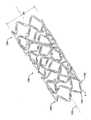
도 1a는 본 발명의 하나의 양태에 따른 팽창(전개) 상태의 가요성 스텐트의 투시도이다.
도 1b는 본 발명의 하나의 양태에 따른 크림핑 상태의 가요성 스텐트의 투시도이다.
도 1c는 본 발명의 하나의 양태에 따른 "절단된 대로(as cut)"(제조된)의 상태의 가요성 스텐트의 투시도이다.
도 2는 본 발명의 하나의 양태에 따른 가요성 스텐트의 평면도이다.
도 3은 도 2의 가요성 스텐트의 분해 평면도이다.
도 4a는 본 발명의 하나의 양태에 따른 가요성 스텐트로부터의 스트럿의 확대 평면도이다.
도 4b는 본 발명의 하나의 양태에 따른 가요성 스텐트로부터의 스트럿의 확대 평면도이다.
도 4c는 본 발명의 하나의 양태에 따른 가요성 스텐트로부터의 스트럿의 확대 평면도이다.
도 4d는 본 발명의 하나의 양태에 따른 가요성 스텐트로부터의 구조상으로 최적화된 스트럿의 확대 평면도이다.
도 5a는 본 발명의 하나의 양태에 따른 가요성 스텐트로부터의 연성 힌지(ductile hinge)의 확대 평면도이다.
도 5b는 본 발명의 하나의 양태에 따른 가요성 스텐트로부터의 연성 힌지의 확대 평면도이다.
도 6a는 본 발명의 하나의 양태에 따른 가요성 스텐트로부터의 원형 힌지 영역의 확대 평면도이다.
도 6b는 본 발명의 하나의 양태에 따른 가요성 스텐트로부터의 원형 힌지 영역의 확대 평면도이다.
도 6c는 본 발명의 하나의 양태에 따른 가요성 스텐트로부터의 원형 힌지 영역의 확대 평면도이다.
도 6d는 본 발명의 하나의 양태에 따른 가요성 스텐트로부터의 원형 힌지 영역의 확대 평면도이다.
도 6e는 본 발명의 하나의 양태에 따른 가요성 스텐트로부터의 원형 힌지 영역의 확대 평면도이다.
도 6f는 본 발명의 하나의 양태에 따른 가요성 스텐트로부터의 원형 힌지 영역의 확대 평면도이다.
도 6g는 본 발명의 하나의 양태에 따른 가요성 스텐트로부터의 원형 힌지 영역의 확대 평면도이다.
도 6h는 본 발명의 하나의 양태에 따른 가요성 스텐트로부터의 원형 힌지 영역의 확대 평면도이다.
도 6i는 본 발명의 하나의 양태에 따른 가요성 스텐트로부터의 원형 힌지 영역의 확대 평면도이다.
도 6j는 본 발명의 하나의 양태에 따른 가요성 스텐트로부터의 원형 힌지 영역의 확대 평면도이다.
도 6k는 본 발명의 하나의 양태에 따른 가요성 스텐트로부터의 원형 힌지 영역의 확대 평면도이다.
도 6l은 본 발명의 하나의 양태에 따른 가요성 스텐트로부터의 원형 힌지 영역의 확대 평면도이다.
도 6m은 본 발명의 하나의 양태에 따른 가요성 스텐트로부터의 원형 힌지 영역의 확대 평면도이다.
도 7은 본 발명의 하나의 양태에 따른 가요성 스텐트로부터의 인덱스 힌지(index hinge)의 확대 평면도이다.
도 8은 나선형 밴드(랩(wrap))의 붙임각(incident angle)을 예시하는, 도 3에 도시된 중심 구역의 확대 평면도이다.
도 9a는 본 발명의 하나의 양태에 따른 도 2에 도시된 가요성 스텐트의 중심 구역을 형성하는 반복 패턴의 일부인 커넥터 스트럿 스트링의 확대 평면도이다.
도 9b는 본 발명의 하나의 양태에 따른 도 2에 도시된 가요성 스텐트의 중심 구역을 형성하는 반복 패턴의 일부인 자유 스트럿 스트링의 확대 평면도이다.
도 10은 본 발명의 하나의 양태에 따른 가요성 스텐트의 평면도이다.
도 11은 도 10의 가요성 스텐트의 분해 평면도이다.
도 12는 본 발명의 하나의 양태에 따른 가요성 스텐트의 평면도이다.
도 13은 도 12의 가요성 스텐트의 분해 평면도이다.
도 14는 본 발명의 하나의 양태에 따른 가요성 스텐트의 평면도이다.
도 15는 도 14의 가요성 스텐트의 분해 평면도이다.
도 16은 본 발명의 하나의 양태에 따른 도 14에 도시된 가요성 스텐트의 중심 구역을 형성하는 반복 패턴의 일부인 자유 스트럿 스트링 및 커넥터 스트럿 스트링의 확대 평면도이다.
도 17은 본 발명의 하나의 양태에 따른 도 12에 도시된 가요성 스텐트의 중심 구역을 형성하는 반복 패턴의 일부인 자유 스트럿 스트링 및 커넥터 스트럿 스트링의 확대 평면도이다.
도 18은 본 발명의 하나의 양태에 따른 도 10에 도시된 가요성 스텐트의 중심 구역을 형성하는 반복 패턴의 일부인 자유 스트럿 스트링 및 커넥터 스트럿 스트링의 확대 평면도이다.
도 19는 본 발명의 하나의 양태에 따른 저장소(depot)를 갖지 않는 가요성 스텐트의 평면도이다.
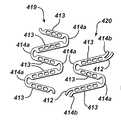
도 20은 본 발명의 하나의 양태에 따른 가요성 스텐트의 평면도이다.
도 21은 도 20의 가요성 스텐트의 분해 평면도이다.
도 22는 본 발명의 하나의 양태에 따른 따른 가요성 스텐트의 평면도이다.
도 23은 도 22의 가요성 스텐트의 분해 평면도이다.
도 24는 본 발명의 하나의 양태에 다른 가요성 스텐트로부터의 원형 힌지 영역의 확대 평면도이다.
도 25는 본 발명의 하나의 양태에 따른 가요성 스텐트의 평면도이다.
도 26은 도 25의 가요성 스텐트의 분해 평면도이다.
도 27은 본 발명의 하나의 양태에 따른 가요성 스텐트의 평면도이다.
도 28은 도 27의 가요성 스텐트의 분해 평면도이다.1A is a perspective view of a flexible stent in an expanded (deployed) state according to one embodiment of the present invention.
1B is a perspective view of a flexible stent in a crimped state according to one embodiment of the present invention.
FIG. 1C is a perspective view of a flexible stent in the "as cut" (manufactured) state according to one aspect of the present invention. FIG.
2 is a top view of a flexible stent according to one embodiment of the present invention.
Figure 3 is an exploded top view of the flexible stent of Figure 2;
4A is an enlarged plan view of a strut from a flexible stent in accordance with one embodiment of the present invention.
4b is an enlarged plan view of a strut from a flexible stent in accordance with an aspect of the present invention.
4C is an enlarged plan view of a strut from a flexible stent in accordance with one embodiment of the present invention.
Figure 4d is an enlarged top view of a structurally optimized strut from a flexible stent in accordance with one embodiment of the present invention.
5A is an enlarged plan view of a ductile hinge from a flexible stent according to one embodiment of the present invention.
Figure 5B is an enlarged plan view of a flexible hinge from a flexible stent in accordance with one embodiment of the present invention.
6A is an enlarged plan view of a circular hinge region from a flexible stent in accordance with one embodiment of the present invention.
6B is an enlarged plan view of a circular hinge region from a flexible stent according to one embodiment of the present invention.
6C is an enlarged plan view of a circular hinge region from a flexible stent in accordance with one embodiment of the present invention.
6D is an enlarged plan view of a circular hinge region from a flexible stent in accordance with one embodiment of the present invention.
6E is an enlarged plan view of a circular hinge region from a flexible stent in accordance with one embodiment of the present invention.
6F is an enlarged plan view of a circular hinge region from a flexible stent according to one embodiment of the present invention.
6G is an enlarged plan view of a circular hinge region from a flexible stent according to one embodiment of the present invention.
6H is an enlarged plan view of a circular hinge region from a flexible stent according to one embodiment of the present invention.
Figure 6i is an enlarged plan view of a circular hinge region from a flexible stent in accordance with one embodiment of the present invention.
6J is an enlarged plan view of a circular hinge region from a flexible stent according to one embodiment of the present invention.
6K is an enlarged plan view of a circular hinge region from a flexible stent in accordance with one embodiment of the present invention.
Figure 61 is an enlarged plan view of a circular hinge region from a flexible stent in accordance with one embodiment of the present invention.
6M is an enlarged plan view of a circular hinge region from a flexible stent according to one embodiment of the present invention.
7 is an enlarged plan view of an index hinge from a flexible stent according to one embodiment of the present invention.
8 is an enlarged plan view of the central zone shown in Fig. 3, illustrating the incident angle of the helical band (wrap). Fig.
FIG. 9A is an enlarged plan view of a connector strut string that is part of a repeating pattern forming a central region of the flexible stent shown in FIG. 2 in accordance with an aspect of the present invention. FIG.
FIG. 9B is an enlarged plan view of a free strut string that is part of a repeating pattern forming a central region of the flexible stent shown in FIG. 2 in accordance with an aspect of the present invention. FIG.
10 is a top view of a flexible stent according to one embodiment of the present invention.
11 is an exploded plan view of the flexible stent of Fig.
12 is a plan view of a flexible stent according to one embodiment of the present invention.
13 is an exploded plan view of the flexible stent of Fig.
14 is a top view of a flexible stent according to one embodiment of the present invention.
15 is an exploded plan view of the flexible stent of Fig.
16 is an enlarged plan view of a free strut string and a connector strut string that are part of a repeating pattern forming a central zone of the flexible stent shown in Fig. 14 according to one aspect of the present invention.
17 is an enlarged plan view of a free strut string and a connector strut string that are part of a repeating pattern forming the central region of the flexible stent shown in Fig. 12 according to one aspect of the present invention.
18 is an enlarged plan view of a free strut string and a connector strut string that are part of a repeating pattern forming the central region of the flexible stent shown in Fig. 10 according to one aspect of the present invention.
Figure 19 is a top view of a flexible stent without a depot according to one aspect of the present invention.
20 is a top view of a flexible stent according to one embodiment of the present invention.
Figure 21 is an exploded plan view of the flexible stent of Figure 20;
22 is a plan view of a flexible stent according to one embodiment of the present invention.
23 is an exploded plan view of the flexible stent of Fig.
24 is an enlarged plan view of a circular hinge region from a flexible stent in accordance with an embodiment of the present invention.
25 is a top view of a flexible stent according to one embodiment of the present invention.
26 is an exploded plan view of the flexible stent of Fig.
27 is a plan view of a flexible stent according to one embodiment of the present invention.
28 is an exploded plan view of the flexible stent of Fig. 27;
본 발명의 스텐트는 매우 가요성이고 전달가능하면서, 여전히 혈관 개방성을 유지하기에 충분한 반경방향 강도를 제공한다. 스텐트는 코발트 크롬 합금, 스테인레스강 합금 또는 니켈 티탄 합금을 포함하는 적합한 재료로부터 제조된 관을 레이저 절단하는 방식과 같은 임의의 적합한 방식으로써 형성될 수 있다. 비록 본 발명의 관상 가요성 스텐트가 본 발명의 하나의 양태를 예시하기 위해 개시되지만, 개시된 본 발명이 예를 들어 맥관, 비맥관 및 말초 혈관, 관(duct) 등과 같은 신체 내의 내강 및 다른 위치에 동등하게 적용될 수 있음을 당업자는 이해할 것이다.The stent of the present invention is highly flexible and deliverable, yet still provides sufficient radial strength to maintain vessel openness. The stent can be formed in any suitable manner, such as by laser cutting a tube made of a suitable material including a cobalt chromium alloy, a stainless steel alloy, or a nickel titanium alloy. Although the tubular flexible stent of the present invention is disclosed to illustrate one aspect of the present invention, it is contemplated that the disclosed invention may be applied to other types of lumens and other locations within the body, such as the vasculature, the vasculature and peripheral blood vessels, ducts, Those skilled in the art will appreciate that the invention is equally applicable.
본 발명의 하나의 양상에 따르면, 가요성 스텐트는 감소된 직경으로 크림핑되고 전달 카테터에 의해 목표 자리까지 신체 내강을 통해 경피 전달되도록 설계된다. 목표 자리는, 예를 들어, 심장 동맥일 수 있다. 일단 전개되면, 가요성 스텐트는 혈관 개방성을 유지하고, 필요에 따라, 제어된 양의 약물 또는 제제를 전달하는 기능을 한다.According to one aspect of the invention, the flexible stent is designed to be crimped to a reduced diameter and transdermally delivered through the body lumen to the target site by the delivery catheter. The target site may be, for example, the heart artery. Once deployed, the flexible stent remains vascular open and functions to deliver a controlled amount of drug or agent, if desired.
본 발명의 하나의 양태에 따른 팽창(전개) 상태, 크림핑 상태 및 "절단된 대로" 또는 제조된 상태의 가요성 스텐트(100)의 투시도가 도 1a, 도 1b 및 도 1c에 각각 도시되어 있다. 스텐트(100)는 도 1c에 도시된 바와 같이 처음 제조되었을 때인 "절단된 대로"의 직경인 D3을 갖는다. 스텐트(100)는 도 1b에 도시된 바와 같이 환자 내로의 삽입을 위해 그리고 혈관을 통한 이동을 위해 제1 직경 D1로, 그리고 도 1a에 도시된 바와 같이 혈관의 목표 지역으로의 전개를 위해 제2 직경 D2로 크림핑되는데, 이때 제2 직경은 제1 직경보다 크다.A perspective view of an inflated (deployed) state, a crimped state, and a
가요성 스텐트(100)는 내강 표면(101) 및 내강으로부터 벗어난 표면(102) 각각과 이들 사이의 두께(벽 두께) "T"를 갖는 구조적 구성요소들의 관형 구성(tubular configuration)을 갖는 원통형이다. 스텐트의 원통형 형상은 길이방향 축(103)을 한정하며, 근위 단부 부분(104) 및 원위 단부 부분(105)을 각각 갖는다.
근위와 원위라는 용어들은 전형적으로 사람의 신체와 관련된 방향 또는 위치를 의미하기 위해 사용된다. 예를 들어, 뼈의 근위 단부는 신체의 중심에 더 가까이 있는 뼈의 단부를 지칭하기 위해 사용될 수 있다. 반대로, "원위"라는 용어는 신체로부터 가장 멀리 있는 뼈의 단부를 지칭하기 위해 사용될 수 있다. 혈관계에서, 근위 및 원위는 때때로 심장으로의 혈류 또는 심장으로부터의 혈류를 각각 나타내기 위해 사용된다. 본 발명에서 기술되는 가요성 스텐트는 동맥계와 정맥계 둘 다를 비롯한 많은 상이한 신체 내강 내에서 사용될 수 있기 때문에, 본 출원에서 "근위" 및 "원위"라는 용어의 사용은 전달의 방향에 대하여 상대적 위치를 기술하기 위해 사용된다. 예를 들어, 본 출원에서 "원위 단부 부분"이라는 용어의 사용은 혈관계 내로 최초로 도입되고 전달 경로에 대하여 신체 내로의 진입 지점으로부터 가장 멀리 있는 스텐트의 단부 부분을 기술한다. 반대로, "근위 단부 부분"이라는 용어의 사용은 전달 경로에 대하여 신체 내로의 진입 지점에 가장 가까이 있는 스텐트의 후방 단부 부분을 기술하기 위해 사용된다.The terms proximal and distal are typically used to refer to a direction or position associated with a person's body. For example, the proximal end of the bone can be used to refer to the end of the bone that is closer to the center of the body. Conversely, the term "distal" can be used to refer to the end of the bone furthest from the body. In the vasculature, proximal and distal are sometimes used to indicate blood flow to or from the heart, respectively. Because the flexible stent described herein can be used in many different body lumens including both the arterial and venous systems, the use of the terms "proximal" and "distal" It is used to describe. For example, the use of the term "distal end portion" in the present application describes the end portion of the stent that is first introduced into the vascular system and furthest from the entry point into the body with respect to the delivery path. Conversely, the use of the term "proximal end portion" is used to describe the posterior end portion of the stent closest to the entry point into the body with respect to the delivery path.
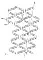
도 2 및 도 3은 본 발명의 하나의 양태에 따른 부분 팽창 상태의 스텐트(100)의 평면도이다. 본원에서 사용되는, 평면도라는 용어는, 하부 가장자리(edge)가 원통의 둘레로 말아져서 상부 가장자리에 연결될 수 있도록, 길이방향 축을 따라 절단하여 편평하게 펼친 스텐트의 2차원(2-D) 도면인 것으로 이해된다.2 and 3 are plan views of a partially expanded
스텐트(100) 구조는 일반적으로 근위 단부 및 원위 단부(104,105)들 각각을 따르는 환형(ring-like)의 단부 섹션(106,107)들, 및 이들 사이의 나선형 내부 섹션(108)을 포함한다. 나선형 내부 섹션(108)은 중심 구역(111), 및 근위 전이 구역 및 원위 전이 구역(109,110)들을 추가로 포함한다. 전이 구역(109,110)들은 중심 구역(111)과 환형의 근위 단부 섹션 및 환형의 원위 단부 섹션(106,107)들 사이에서 전이한다. 도 3은 상이한 섹션들과 구역들을 도시하는 스텐트(100)의 분해 평면도이다.The
스텐트(100)는 원주방향으로 배향된 일련의 연성 힌지(114)들에 의해 연결된, 길이방향으로 배향된 복수의 스트럿(113)들을 포함한다. 원주방향으로 인접한 스트럿(113)들은 대향 단부들에서 힌지(114)에 의해 실질적으로 S자 또는 Z자 형상인 사인파형 패턴으로 연결되어 밴드를 형성한다. 가요성 커넥터(112)들이 다양한 하중 조건하에서의 구조적 안정성을 위해 스텐트(100) 구조의 전체에 걸쳐 분포되어 있다. 도 1 내지 도 3에 도시된 스텐트 디자인은 하나의 가요성 커넥터 기하형태를 갖지만, 매우 다양한 커넥터 기하형태가 고려된다. 전반적으로 도 6b 내지 도 6h를 참조한다.The
나선형 내부 섹션(108)이 환형의 단부 섹션(106,107)들에 처음으로 연결되는 스텐트(100)의 영역은 앵커 지점(anchor point)으로 지칭되며, 그 위치에서의 힌지(114)는 "앵커 힌지"로 지칭된다. 이러한 "출발(take off)" 지점은 디자인 제약에 근거하여 달라질 수 있다. 부가적으로, 붙임각, 스트럿 두께, 스트럿 폭, 힌지 폭, 힌지 길이, 저장소 위치 및 크기, 및 연결 길이는 최적화 및 디자인 제약에 근거하여 달라질 수 있다.The area of the
본원에 사용되는, 길이방향으로, 원주방향으로 및 반경방향으로 배향된 이라는 용어는 스텐트(100) 및 길이방향 축(103)에 대한 특정 방향을 나타내는 것으로 알려져 있다. 길이방향으로 배향된 멤버는 (이의 축을 따라) 단부로부터 단부까지 일반적으로 길이방향 축(103)의 방향으로 배향된다. 도면들을 검토한 후에는, 스텐트(100)가 도 1b에 도시된 바와 같이 크림핑 상태로 있을 때, 스텐트(100)가 도 1a에 도시된 바와 같이 팽창된 전개 상태로 있을 때보다, 스트럿(113)의 길이방향은 길이방향 축에 평행하도록 더 근접해 있음이 명백하다. 그럼에도 불구하고, 각각의 경우에, 스트럿(113)의 축이 실질적으로 길이방향 축과 동일한 방향으로 배향되므로 스트럿(113)은 길이방향으로 배향된 것으로 간주된다. 원주방향으로 배향된 멤버, 예를 들어 힌지(114)는 실질적으로 관형 스텐트(100)의 원주를 따라 배향된다. 유사하게는, 반경방향 또는 반경방향으로의 배향은 단면에서 일반적으로 길이방향 축으로부터 외측으로 관형 스텐트(100)의 원주로 연장되는 반경을 따른다.As used herein, the terms longitudinally, circumferentially, and radially oriented are known to denote specific directions for the
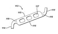
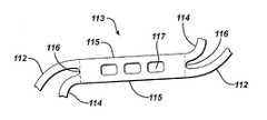
도 4a, 도 4b 및 도 4c는 본 발명의 다양한 양태에 따른 전형적인 스트럿(113)들을 도시한 것이다. 각각의 스트럿(113)은 길이방향으로 연장되는 긴 변(115)들 및 원주방향으로 연장되는 짧은 변(116)들을 갖는 실질적으로 직사각형인 형상의 멤버이다. 대향하는 긴 변(115)들 및 짧은 변(116)들은 실질적으로 서로 평행하여 도 4a에 도시된 스트럿(113)에 의해 나타낸 바와 같이 거의 완전한 직사각형을 형성할 수 있거나, 경사지거나 기울어져 도 4b에 도시된 스트럿(113)에 의해 나타낸 바와 같이 테이퍼링된(tapered) 스트럿(113)을 형성할 수 있다. 도 4a 및 도 4b에서 볼 수 있는 바와 같이, 힌지(114)들은 스트럿의 짧은 변(116)들을 따라 스트럿(113)에 부착되지만, 스트럿의 폭[짧은 변(116)의 길이]은 본 발명의 바람직한 양태에서의 힌지(114)의 폭보다 크다. 도 4b에 도시된 바와 같이, 가요성 커넥터(112)들은 스트럿(113)들의 짧은 변(116)들을 따라 스트럿(113)들에 연결되지만, 힌지(114)들에 연결되지 않는다.4A, 4B, and 4C illustrate
도 4c는 스텐트(100) 디자인의 일부 양태에서 발견될 수 있는 독특한 스트럿(113)을 나타낸다. 도 4c에 도시된 스트럿(113)은 (이하에서 기술되는 바와 같은) 원형 힌지(114)들에 대한 2개의 연결 지점들 및 가요성 커넥터(112)들에 대한 2개의 연결 지점들을 특징으로 한다. 이러한 스트럿(113)은 근위 및 원위 단부들에서 [힌지(114)들과 가요성 커넥터(112)들의 연결 지점들에서] 폭이 가장 넓고, 길이방향 스트럿(113) 길이의 중간 지점 부근에서의 이의 최소 폭으로 테이퍼링된다. 즉, 도 4c에 도시된 스트럿(113)의 짧은 변(116)의 길이는 스트럿(113)의 길이방향 중심 지점 부근에서의 폭보다 크다.Figure 4c shows a
스트럿(113)들은 적어도 하나의 제제를 함유하기 위한 하나 이상의 저장소(117)들을 가질 수 있다. 저장소(117)들은 제제를 유지할 수 있는 임의의 형태의 리세스(recess), 채널, 구멍(hole) 또는 공동(cavity)일 수 있지만, 바람직하게는 스텐트(100)를 관통하여 정밀하게 형성된 관통 구멍들이다. 바람직한 양태에서, 관통 구멍은 내강 표면으로부터 내강으로부터 벗어난 표면까지 스트럿을 통과한다. 이러한 바람직한 구성은 제제 또는 제제들이 스텐트(100)의 내강 변 및 내강으로부터 벗어난 변을 따라 반경방향 내측 및 외측 방향 둘 다로 전달되게 할 수 있다. 또한, 저장소(117)는, 단독인 중합체 인레이(polymer inlay), 또는 용액 등의 상태의 하나 이상의 제제들을 함유하는 중합체 인레이로 충전될 수 있다. 또한, 동일한 스텐트 내의 다양한 저장소(117)들이 동일하거나 상이한 제제들로 충전될 수 있으며, 동일하거나 상이한 농도의 제제들을 가질 수 있다. 임의의 개개의 저장소(117)가 하나 또는 복수의 제제들로 충전될 수 있으며, 이 제제들은 장벽 층(barrier layer)에 의해 분리될 수 있다. 장벽 층은 제제들을 분리시키기 위해 필요에 따라 저장소(117) 내에서 다양한 구성들로 배치될 수 있다. 바람직한 양태에서, 장벽 층은 내강 스텐트 표면에 평행하게 배향된다.The
스트럿(113)은 도 4a 내지 도 4c에 도시된 바와 같이 대칭적으로 크기가 정해지는 저장소(117)들을 가질 수 있거나, 도 4d에 도시된 바와 같이 구조상으로 최적화된 저장소(117)들을 포함할 수 있다. 구조상으로 최적화된 저장소(117)들은 임의의 주어진 스트럿(113) 크기에 대해 저장소(117) 용적을 최대화하면서, 스텐트(100) 팽창시 구조적 완전성을 유지하는데 중요한 재료의 추가 또는 제거를 통해 전체 피쳐의 응력 상태를 감소시키도록 설계된다.
본원에서 사용되는 "제제"라는 용어는 하기를 포함하는 임의의 치료적 또는 약제학적 제제 또는 약물일 수 있다: 항증식제/세포분열억제제, 예컨대 천연 제품, 예를 들어 빈카 알칼로이드(즉, 빈블라스틴, 빈크리스틴 및 비노렐빈), 파클리탁셀, 에피다이포도필로톡신(즉, 에토포사이드, 테니포사이드), 항생제[닥티노마이신(악티노마이신 D), 다우노루비신, 독소루비신 및 이다루비신], 안트라사이클린, 미톡산트론, 블레오마이신, 플리카마이신(미트라마이신) 및 미토마이신, 효소(L-아스파라긴을 전신적으로 대사하며, 그 자신의 아스파라긴을 합성하는 능력을 갖지 않는 세포들을 제거하는 L-아스파라기나아제); 항증식성/세포분열억제성 알킬화제, 예를 들어 질소 머스타드(메클로르에타민, 사이클로포스파미드 및 유사체, 멜팔란, 클로람부실), 에틸렌이민 및 메틸멜라민(헥사메틸멜라민 및 티오테파), 알킬 설포네이트-부설판, 니트로소우레아[카르무스틴(BCNU) 및 유사체, 스트렙토조신], 트라제네스-다카르바지닌(trazenes-dacarbazinine)(DTIC); 항증식성/세포분열억제성 항대사물질, 예를 들어 엽산 유사체(메토트렉세이트), 피리미딘 유사체(플루오로우라실, 플록스우리딘, 및 사이타라빈), 퓨린 유사체 및 관련 억제제(메르캅토퓨린, 티오구아닌, 펜토스타틴 및 2-클로로데옥시아데노신{클라드리빈}); 백금 배위 착체(시스플라틴, 카르보플라틴), 프로카르바진, 하이드록시우레아, 미토탄, 아미노글루테티미드; 호르몬(즉, 에스트로겐); 항응고제(헤파린, 합성 헤파린 염 및 기타 트롬빈 억제제); 피브린용해제(예를 들어, 조직 플라스미노겐 활성제, 스트렙토키나아제 및 유로키나아제), 아스피린, 디피리다몰, 티클로피딘, 클로피도그렐, 압식시맙; 이동억제제(antimigratory); 분비억제제[브레벨딘(breveldin)]; 항염증제: 예를 들어 부신피질 스테로이드(코르티솔, 코르티손, 플루드로코르티손, 프레드니손, 프레드니솔론, 6α-메틸프레드니솔론, 트리암시놀론, 베타메타손, 및 덱사메타손), 비-스테로이드 제제(살리실산 유도체, 즉 아스피린); 파라-아미노페놀 유도체, 즉 아세토미노펜; 인돌 및 인덴 아세트산(인도메타신, 설린닥 및 에토달락), 헤테로아릴 아세트산(톨메틴, 다이클로페낙 및 케토롤락), 아릴프로피온산(이부프로펜 및 유도체), 안트라닐산(메페남산 및 메클로페남산), 에놀린산(피록시캄, 테녹시캄, 페닐부타존 및 옥시펜타트라존), 나부메톤, 금 화합물(오라노핀, 오로티오글루코스, 금 나트륨 티오말레이트); 면역억제제: (사이클로스포린, 타크롤리무스(FK-506), 시롤리무스(라파마이신), 아자티오프린, 미코페놀레이트 모페틸); 혈관신생: 혈관 내피 성장 인자(VEGF: vascular endothelial growht factor), 섬유아세포 성장 인자(FGF: fibroblast growth factor); 산화질소 공여체; 안티-센스 올리고 뉴클레오티드 및 이들의 조합물.As used herein, the term "agent" may be any therapeutic or pharmaceutical agent or drug including antiproliferative / mitotic inhibitors such as natural products such as vinca alkaloids Anticholinergic agents such as antibiotics (Dactinomycin (Actinomycin D), Daunorubicin, Doxorubicin and Dirubicin), Anthraxin L-asparagine (L-asparagine), which systemically metabolizes cyclin, mitoxantrone, bleomycin, plicamycin (mitramycin) and mitomycin, enzyme (L-asparagine and removes cells not capable of synthesizing its own asparagine Better); Antiproliferative / cytostatic alkylating agents such as nitrogen mustards (mechlorethamine, cyclophosphamide and analogues, melphalan, chlorambucil), ethyleneimine and methylmelamines (hexamethylmelamine and thiotepa), Alkyl sulphonate-platelets, nitrosourea [Carmustine (BCNU) and analogs, streptozocin], trazeses-dacarbazinine (DTIC); Antiproliferative / cytostatic antimetabolites such as folic acid analogs (methotrexate), pyrimidine analogs (fluorouracil, phloxuridine, and cytarabine), purine analogues and related inhibitors (mercaptopurine, thio Guanine, pentostatin and 2-chlorodeoxyadenosine {Cladribine}); Platinum coordination complexes (cisplatin, carboplatin), proccarbazine, hydroxyurea, mitotan, aminoglutetimide; Hormones (i. E., Estrogens); Anticoagulants (heparin, synthetic heparin salts and other thrombin inhibitors); Fibrinolytic agents (e.g., tissue plasminogen activator, streptokinase, and europine), aspirin, dipyridamole, ticlopidine, clopidogrel, Antimigratory; Secretion inhibitor [breveldin]; Anti-inflammatory agents such as corticosteroids (cortisol, cortisone, flooded cortisone, prednisone, prednisolone, 6α-methylprednisolone, triamcinolone, betamethasone, and dexamethasone), non-steroidal agents (salicylic acid derivatives, ie aspirin); Para-aminophenol derivatives, i.e., acetominophen; (Indomethacin, sulindac and etodalac), heteroaryl acetic acids (tolmetin, diclofenac and ketololac), arylpropionic acid (ibuprofen and derivatives), anthranilic acids (mefenamic acid and meclofenanic acid) , Enolic acids (pyroxycam, tenoxycam, phenylbutazone and oxypentrazone), nabumetone, gold compounds (auranofin, aurothioglucose, sodium gold thiomalate); Immunosuppressants: (cyclosporine, tacrolimus (FK-506), sylolimus (rapamycin), azathioprine, mycophenolate mopetil); Angiogenesis: vascular endothelial growth factor (VEGF), fibroblast growth factor (FGF); Nitric oxide donors; Anti-sense oligonucleotides and combinations thereof.
하나 이상의 제제들이 내강 또는 내강으로부터 벗어난 스텐트(100) 표면의 적어도 일부를 따라 저장소(117)들 중 하나 이상에 분포되거나, 또는 저장소들 및/또는 스텐트 표면들의 임의의 조합에 분포될 수 있다. 바람직한 양태에서, 제제는 저장소(117)들에만 분포되어, 노출되는 제제 표면적이 스텐트(100) 표면(내강 표면, 내강으로부터 벗어난 표면, 또는 둘 다의 표면)의 저장소 개구의 단면적으로 제한된다. 이러한 디자인은 환자 내로의 삽입시에는 실질적으로 상기 제제로 피복되지 않은 비피복 금속(bare metal)의 표면적을 갖는 스텐트(100)로부터의 제제 전달을 허용한다. 바람직한 양태에서, 스텐트(100)의 노출된 비피복 금속 표면적은 환자 내로의 스텐트(100)의 삽입시에는 40 내지 95%이며, 가장 바람직하게는 환자 내로의 스텐트(100)의 삽입시에 대략 75%가 비피복 금속이다. 즉, 스텐트(100)의 표면적은 대략 25% 제제 및 대략 75% 비피복 금속이다. 제제가 방출됨에 따라, 스텐트(100)는 전적으로 비피복 금속 스텐트가 된다.One or more formulations may be distributed in one or more of the
바람직한 양태에서, 저장소(117)들은 사용된 스텐트의 직경 또는 길이와 무관하게 전개된 스텐트(100)의 단위 표면적당 일관된 제제 투여량을 제공하도록 스트럿 패턴의 전체에 걸쳐 거의 균일하게 분포된다. 제품 디자인을 충족시키기 위해 필요에 따라 스트럿(113)들은 다양한 길이, 붙임각, 저장소 구성 및 폭을 가질 수 있다.In a preferred embodiment, the
연성 힌지(114)들은 원주방향으로 인접한 2개의 스트럿(113)들 사이의 연결 구성요소로서 사용된다. 스텐트(100)에는 두가지 타입의 연성 힌지(114)들이 발견된다. 도 5a 및 도 5b는 본 발명의 하나의 양태에서 발견되는 2개의 전형적인 연성 힌지들을 도시한 것이다. 도 5a는 원주방향으로 인접한 2개의 스트럿(113)들을 연결하는 단일 "자유 힌지(free hinge)"(114a)를 나타낸다. 바람직한 양태에서, 이러한 자유 힌지(114a)는 "C"자 형상이며, 만곡된 섹션 상에서 정점 지점을 통과하여 그어진 기준선 "A"에 대해 실질적으로 대칭이다. 도 5b는 원주방향으로 인접한 2개의 스트럿(113)들을 연결하는 연성 힌지(114b)를 나타내는데, 여기서 스트럿들 중 하나는 가요성 커넥터(112)에 추가로 연결된다. 이러한 연성 힌지(114b)는 형상이 도 5a에 개시된 "C"자 형상의 자유 힌지(114a)보다 더 원형이며, 때때로 본원에서 "원형 힌지"(114b)로 지칭된다. 자유 힌지(114a)들 및 커넥터 힌지(114b)들이 여기에서는 별도로 구별되지만, 이들은 때때로 일반적으로 둘 다 연성 힌지(114)들로 지칭된다. 원형 힌지(114b)를 둘러싸는 영역들은 원형 힌지 영역으로 지칭된다. 가요성 커넥터(112) 및 원형 연성 힌지(114b) 둘 다는 원형 힌지 영역에서 스트럿(113)의 동일한 짧은 변(116)에 연결되지만, 이들은 서로 연결되지는 않는다.The flexible hinges 114 are used as connecting elements between two circumferentially
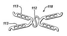
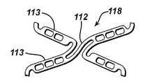
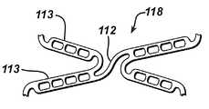
도 6a는 나선형 섹션(108)의 인접한 권선부들 상의 2개의 스트럿 쌍들 사이의 연결 지점으로서 작용하는 "원형 힌지 영역"(118)을 더욱 상세하게 설명한 것이다. 이러한 힌지 영역(118)은 수개의 컴포넌트(component)들을 포함하며, 스트럿 쌍을 형성하는 원주방향으로 인접한 스트럿(113)들 사이에 연성 영역을 제공하면서, 가요성 커넥터(112)에 의해 길이방향으로 인접한 스트럿 쌍들 사이에 필요한 연결성을 제공한다. 조합될 때, 길이방향으로 인접한 스트럿 쌍들 및 상호연결되는 가요성 커넥터(112)는 "쿼드(quad) 힌지 영역들"로 알려진 영역들을 발생시킨다. 이들 영역들은 원형 힌지(114b)들 및 가요성 커넥터(112)들을 통해 직접적으로 또는 간접적으로 연결되는 4개의 스트럿들로 구성된다. 붙임각, 힌지(114b) 폭, 테이퍼링 정도, 길이 및 구멍 패턴은 스텐트들의 의도된 디자인, 피쳐의 위치 및 스텐트 성능 최적화에 따라 변화되기 쉽다. 도 6b 내지 도 6m은 원형 힌지 영역(118)에서 인접한 스트럿 쌍들을 연결하기 위해 사용될 수 있는 다양한 커넥터(112)들을 도시하였다.6A illustrates the "circular hinge region" 118, which acts as a point of connection between two strut pairs on adjacent turns of
도 7은 스텐트(100)의 제조 공정 동안의 또 다른 중요한 주요 스텐트 속성을 도시한 것이다. 원으로 둘러싸서 표시한 연성 힌지(114)는 "인덱스 힌지"로 알려져 있다. 이러한 "인덱스 힌지"는, 연성 힌지 또는 스트럿(113) 헤드가 사인파 단부 환 내의 나머지 스트럿들 상의 스트럿(113) 헤드들의 평면을 지나 돌출하게 하는 더 긴 스트럿(113) 길이를 특징으로 한다. 용이한 도시를 위하여, 기준선 A가 길이방향 축(103)에 수직하게, 그리고 인덱스 힌지의 위와 아래 둘 다의 힌지(114)들의 곡면(curved surface)들에 접하여 그어져 있다. 기준선 B는 길이방향 축(103)에 수직하게, 그리고 인덱스 힌지를 나타내는 힌지(114)의 곡면에 접하여 그어져 있다. 길이방향 축을 따른 기준선 A와 기준선 B 사이의 거리가 인덱스에 의해 제공된 오프셋(offset)이다. 이러한 오프셋은 스텐트(100)의 배향을 결정하는 것을 돕는 기준 지점으로서 역할한다. "인덱스 힌지"는 환형의 근위 단부 섹션 및 환형의 원위 단부 섹션(106,107)들을 따라 임의의 위치에 존재할 수 있다.FIG. 7 illustrates another important key stent attribute during the manufacturing process of the
일반적으로 말하자면, 연성 힌지(114)들은 주위의 스트럿(113)들보다 폭이 실질적으로 더 얇은 변형가능한 구성요소들이다. 이로 인해 연성 힌지(114)들이 변형된 상태에서 가요성을 여전히 유지하면서 소성 변형에 견디게 한다. 따라서, 스트럿(113)들은 연성 힌지(114)들보다 훨씬 더 강성이며, 그러므로 스텐트 팽창 동안에 어떠한 소성 변형도 겪지 않는다. 스트럿(113)은 본질적으로 강체들로서 회전하는 반면에, 연성 힌지(114)들은 스텐트 팽창과 관련된 소성 변형에 견디도록 설계된다. 그 결과, 스트럿(113)들 내의 저장소(117)들은 팽창 동안에 제제들 및/또는 중합체 인레이들의 손상 또는 분리를 야기할 수 있는 과도한 응력으로부터 보호된다. 저장소(117)들은 이상적으로는 스텐트 전개 과정 전체에 걸쳐 응력이 없는 상태이다.Generally speaking, the
본 발명의 바람직한 양태에서, 연성 힌지(114)들은, 이 연성 힌지들이 스텐트(100)에 충분한 반경방향 강성을 제공하면서, 완전 팽창시의 피크 소성 변형이 물질의 변형 지지 능력을 초과하지 않음을 보장하도록, 폭 테이퍼링(width tapering)을 사용하여 최적화된다. 이러한 폭 테이퍼링은 연성 힌지(114)의 길이를 따라 완만하고 균일한 소성 변형 분포를 달성하도록, 각각의 힌지(114) 타입에 대해 최적화된다. 연성 힌지(114)에서의 변형 분포를 완만하게 하고 따라서 변형 집중을 제거함으로써 폭 및 이에 의해 강성이 최대화된다. 연성 힌지(114)의 강성을 최대화하는 것은 스텐트(100)에 반경방향 강성 및 피로 내구성(fatigue durability)을 제공함에 있어서 유리하다.In a preferred embodiment of the invention, the
일반적으로, 테이퍼링된 연성 힌지(114)의 폭은 힌지(114)의 루트(root)에 접근하는 동안 점차적으로 증가하는데, 여기서 상기 힌지(114)는 더 넓은 스트럿(113)(또는 더 강성의 구조물) 중으로의 급격한 전이부와 만난다. 이로 인해 소성 변형이 힌지의 루트에 집중되는 것이 방지되는데, 이는 테이퍼링된 힌지 루트가 더 강성이고 따라서 소성 변형을 힌지(114)의 중심 부분에 분포시키기 때문이다. 곡선의 정점을 포함하는 연성 힌지(114)의 중심 부분은 일반적으로 균일한 폭을 갖는다.Generally, the width of the tapered
도 2 및 도 3을 다시 살펴보자면, 환형의 단부 섹션(106,107)들은, 엔드리스 환(endless ring) 형태로 밴드를 형성하기 위해, 대향 단부들에서, 원주방향으로 배향된 복수의 연성 힌지(114)들에 의해 실질적으로 사인파 S자 또는 Z자 형상인 패턴으로 연결되는, 원주방향으로 배열되고 길이방향으로 배향된 복수의 스트럿 멤버(113)들을 포함한다. 도시된 양태에서, 단부 섹션(106,107)들은 스텐트 디자인을 최적화하고 나선형 내부 섹션(108)이 환형의 단부 섹션(106,107)들에 처음으로 연결되는 앵커 지점에서의 연결을 위해 필요한 기하형태를 제공하기 위해 필요에 따라 다양한 길이의 스트럿(113)들로부터 형성된다.Referring again to Figures 2 and 3, the
환형의 단부 섹션(106,107)들 사이에 스텐트(100)의 나선형 내부 섹션(108)이 위치하는데, 여기서 사인파형으로 배열되는 스트럿(113)들 및 힌지(114)들의 밴드는 나선형 경로를 따른다. 내부 섹션(108)의 나선형 밴드는 스트럿(113)들을 짧은 길이와 긴 길이가 교호하는 반복 패턴으로 배열함으로써 달성된다. 나선형 내부 섹션(108)은 근위 전이 구역 및 원위 전이 구역(109,110)들 각각과, 중심 구역(111)으로 추가로 나뉠 수 있다.A helical
중심 구역(111)은 스트링 패턴을 형성하도록 편성되는 근접한(contiguous) 스트럿 멤버(113)들 및 힌지 멤버(114)들의 그룹으로부터 형성된 스트링들(구성요소들의 집합체)을 포함한다. 본 발명의 하나의 양태에서, 근접한 스트링들은 상이한 스트링 패턴들을 가지며, 반복하는 스트링들은 반복하는 중심 패턴을 형성하도록 기하학적으로 대칭이다. 본 발명의 바람직한 양태에서, 반복하는 중심 패턴은 2개의 상이한 반복 스트링들로 이루어진다. 따라서 중심 구역(111)은 일정한 피치(pitch) 및 붙임각을 갖는다.The
본원에서 사용되는 피치라는 용어는 주어진 면적에 걸쳐 있는 사인파 회선(turn)의 개수를 의미하는 것으로 이해된다. 이는 기어의 직경 피치와 유사한 명명이다. 피치가 클수록, 사인파 회선의 개수가 커지는데, 즉 사인파 밴드가 길이방향 축(103) 둘레로 권선될 때 랩(wrap)당 더 많은 개수의 스트럿(113)들 및 연성 힌지(114)들이 발견될 것이다. 이로 인해 스트럿(113)들 및 힌지(114)들의 매우 조밀한 패턴이 생성된다. 반대로, 피치가 작을수록, 사인파 회선의 개수는 작아지며, 따라서 사인파 밴드가 길이방향 축(103) 둘레로 권선될 때 랩당 더 작은 개수의 스트럿(113)들 및 힌지(114)들이 발견될 것이다. 붙임각이라는 용어는 구체적으로 스텐트(100)의 나선형 권선부 섹션과 관련되며, 사인파 밴드가 길이방향 축과 이루는(길이방향 축에 말아지는) 각도를 의미하는 것으로 이해된다.The term pitch as used herein is understood to mean the number of sine wave turns over a given area. This is a naming similar to the gear diameter pitch. The larger the pitch, the greater the number of sinusoidal lines, i.e., the greater number of
도 8은 도 3에 도시된 중심 구역(111)의 2차원 확대도이다. 제1 기준선 "A"가 길이방향 축(103)에 평행하게 그어져 있다. 제2 기준선 "B"가 사인파 밴드의 방향을 나타내도록 그어져 있다. 붙임각(α)은 기준선 A와 기준선 B 사이의 각도이다.8 is a two-dimensional magnified view of the
도 9a 및 도 9b는 본 발명의 하나의 양태에 따른 스텐트(100)의 중심 구역(111)을 형성하는 반복 패턴의 일부인 2개의 스트럿 스트링들을 도시한 것이다. 도 3, 도 8, 도 9a 및 도 9b를 참조하면, 중심 구역(111)은 도 9b에 도시된 자유 스트럿 스트링(119)을 갖는 원위 전이 구역(110)의 근위 단부에서 시작된다. 도시된 자유 스트럿 스트링(119)은 각각의 단부에서 자유 힌지(114a)에 의해 짧은 2- 저장소 스트럿(113)에 연결되는 긴 3-저장소 스트럿(113)을 포함한다. 자유 스트럿 스트링(119)은 이의 근위 단부에서 커넥터 스트럿 스트링(120)의 원위 단부에 부착된다. 커넥터 스트럿 스트링(120)은 이의 근위 및 원위 단부들의 커넥터 힌지(114b), 및 자유 힌지(114a)들에 의해 연결되는 3개의 긴 (3-저장소) 스트럿(113)들과 2개의 짧은 (2-저장소) 스트럿(113)들의 교호하는 배열을 포함한다. 교호하는 자유 스트럿 스트링(119)과 커넥터 스트럿 스트링(120)들의 이러한 패턴은 중심 구역(111)이 근위 전이 구역(109)과 만날 때까지 계속된다. 도 3에 도시된 양태는 5개의 자유 스트럿 스트링(119)들 및 4개의 커넥터 스트럿 스트링(120)들을 포함하는 중심 구역을 갖는다. 스텐트(100)의 길이는, 근위 전이 구역 및 원위 전이 구역(109,110)들과 환형의 근위 단부 섹션 및 환형의 원위 단부 섹션(106,107)들을 개시된 바와 같이 유지하면서 중심 구역(111)을 부가하거나 단축시킴으로써, 즉 반복 패턴을 유지하기 위해 필요한 바와 같이 자유 스트럿 스트링(119)들 또는 커넥터 스트럿 스트링(120)들을 부가하거나 제거함으로써 변화시킬 수 있다.Figures 9a and 9b illustrate two strut strings that are part of a repeating pattern forming a
근위 전이 구역 및 원위 전이 구역(109,110)들은 가변 피치의 섹션들이며, 반복성 또는 대칭성이 없다. 근위 전이 구역 및 원위 전이 구역(109,110)들은 중심 구역(111)과 환형의 근위 단부 섹션 및 환형의 원위 단부 섹션(105,107)들 사이에서 전이함에 있어서 피치의 점차적인 감소를 제공하도록 구성된다. 근위 전이 구역 및 원위 전이 구역(109,110)들은 앵커 힌지로 불리는 연결성 기하형태부에 의해 환형의 근위 단부 섹션 및 환형의 원위 단부 섹션(106,107)들에 각각 연결된다.The proximal and
앞서 언급된 도면들에 도시된 스텐트(100) 디자인들은 개방 셀(open cell) 디자인으로 알려져 있는데, 이는 길이방향으로 인접한 사인파 구성요소들의 권선부들 사이의 커넥터들이 길이방향으로 인접한 힌지(114) 또는 스트럿(113)마다 걸쳐져 있기보다는 구조물을 통해 간헐적으로만 존재함을 의미한다. 길이방향으로 인접한 힌지 또는 스트럿마다 연결되는 디자인은 폐쇄 셀(closed cell) 디자인으로 알려져 있다. 개방 셀 구조는 일반적으로 폐쇄 셀 구조보다 가요성이 더 크다.The
상기한 바와 같이, 스텐트(100)의 일반적인 구조는 각각의 단부에서 환형의 단부 섹션(106,107)들을 갖는 나선형 내부 섹션(108), 및 다양한 하중 조건하에서의 구조적 안정성을 위해 구조를 통해 분포되어 있는 커넥터(112)들을 포함한다. 나선형 내부 섹션(108)은 일정한 피치 및 붙임각을 갖는 중심 구역(111)과, 근위 전이 구역 및 원위 전이 구역(109,110)들 각각으로 추가로 나뉠 수 있다. 이러한 일반적인 구조는 상이한 크기의 다양한 스텐트들에 대해 동일하게 유지되지만, 구성요소들(스트럿들, 힌지들 및 가요성 커넥터들)의 기하형태 및 패턴은 다양한 원하는 스텐트 직경에 적합하도록 필요에 따라 변할 수 있다.As described above, the general structure of the
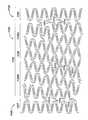
도 10 내지 도 15는 상이한 직경 크기의 스텐트들에 대한 스텐트 디자인들의 여러 양태를 도시한 것이다. 도 10, 도 12 및 도 14는 상이한 크기 및 패턴의 스텐트(200,300,400)들 각각을 도시하는, 도 2와 유사한 2차원 평면도이다. 도 11, 도 13 및 도 15는 상이한 섹션들 및 구역들을 도시하는, 도 3과 유사한, 스텐트(200,300,400)들 각각의 분해 평면도이다. 용이한 도시를 위하여, 유사한 도면 번호들이 스텐트(100)의 유사한 구성요소들에 부여되었으며, 스텐트(100)와 관련된 구성요소들의 설명이 스텐트(200,300,400)들의 유사한 구성요소들에 동등하게 적용된다고 이해된다.Figures 10-15 illustrate various aspects of stent designs for different diameter sized stents. Figures 10, 12 and 14 are two-dimensional plan views similar to Figure 2, showing each of the
각각의 스텐트 패턴 디자인은 스텐트의 의도된 목표 혈관의 치료에 근거하여 목표 최적 결과에 맞게 설계된다. 도 10 및 도 11은 초소형 직경의 목표 혈관 병변을 위해 의도된 스텐트(200)의 하나의 양태를 도시한 것이다. 초소형 직경의 스텐트 계열은 몇몇 디자인 특징들을 통해 매우 작은 직경의 혈관을 위해 최적화되었으며, 이것은 더 작은 직경의 튜빙 재료로부터 제조되는 것을 의미한다.Each stent pattern design is designed to target optimal results based on the treatment of the intended target vessel of the stent. Figures 10 and 11 illustrate one aspect of a
초소형 스텐트에 대한 본 양태는 각각의 환형의 단부 섹션(206,207)들에서 10개의 스트럿(213)들로 구성되는 환형의 사인파 근위 단부 섹션 및 환형의 사인파 원위 단부 섹션(206,207)들을 포함한다. 환형의 단부 섹션(206,207)들 사이에 스텐트(200)의 나선형 내부 섹션(208)이 위치하는데, 여기에서는 스트럿(213)들 및 힌지(214)들의 사인파 배열이 나선형 경로를 따른다. 내부 섹션(208)의 나선형 경로는 밴드를 형성하도록 스트럿(213)들을 짧은 길이와 긴 길이가 교호하는 반복 패턴으로 배열함으로써 달성된다. 각각의 내부 밴드들에서 권선부당 9개의 스트럿(213)들이 있다. 더 적은 개수의 스트럿들은 중요한 처리 파라미터들을 유지하면서 증가된 스텐트 성능을 허용한다. 나선형 내부 섹션(208)은 도 11에 도시된 바와 같이 근위 전이 구역 및 원위 전이 구역(209,210)들 각각과 중심 구역(211)으로 추가로 나뉠 수 있다.This aspect of the miniature stent includes an annular sinusoidal proximal end section and an annular sinusoidal distal end section 206,207, which is comprised of ten
중심 구역(211)은 밴드에 반복 패턴을 형성하도록 기하학적으로 대칭인 반복 스트럿 스트링들 또는 스트럿들의 집합체로 이루어진다. 따라서, 중심 구역(211)은 일정한 피치 및 붙임각을 갖는다. 반복하는 내부 패턴은 9-스트럿 반복 내부 패턴을 형성하도록 교호하는 2개의 3-스트럿 패턴들로 구성된다.The
도 18은 본 발명의 하나의 양태에 따라 스텐트(200)의 중심 구역(211)으로부터 반복 패턴의 일부인 2개의 스트럿 스트링(219,220)들을 도시한 것이다. 도 10, 도 11 및 도 18을 참조하면, 중심 구역(211)은 도 18에 도시된 자유 스트럿 스트링(219)을 갖는 근위 전이 구역(209)의 원위 단부에서 시작된다. 도시된 자유 스트럿 스트링(219)은 각각의 단부에서 자유 힌지(214a)에 의해 짧은 (2-저장소) 스트럿(213)에 연결되는 긴 (4-저장소) 스트럿(213)을 포함한다. 자유 스트럿 스트링(219)은 이의 원위 단부에서 커넥터 스트럿 스트링(220)의 근위 단부에 부착된다. 커넥터 스트럿 스트링(220)은 이의 근위 및 원위 단부들에서의 커넥터 힌지(214b), 및 자유 힌지(214a)에 의해 연결되는 2개의 긴 (4-저장소) 스트럿(213)과 1개의 짧은 (2-저장소) 스트럿(213)의 교호하는 배열을 포함한다. 교호하는 자유 스트럿 스트링(219)과 커넥터 스트럿 스트링(220)의 이러한 패턴은 중심 구역(211)이 원위 전이 구역(210)과 만날 때까지 계속된다. 도 10 및 도 11에 도시된 양태는 6개의 자유 스트럿 스트링(219)들 및 6개의 커넥터 스트럿 스트링(220)들을 포함하는 중심 구역을 갖는다.Figure 18 shows two
중간 크기의 스텐트에 대한 본 양태는 12개의 스트럿(313) 단부 환들로 구성되는 환형의 사인파 근위 단부 섹션 및 환형의 사인파 원위 단부 섹션(306,307)들을 포함한다. 환형의 단부 섹션(306,307)들 사이에 스텐트(300)의 나선형 내부 섹션(308)이 위치하는데, 여기서 밴드 중의 스트럿(313)들 및 힌지(314)들의 사인파 배열이 나선형 경로를 따른다. 내부 섹션(308)의 나선형 경로는 밴드를 형성하도록 스트럿(313)들을 교호하는 짧은 길이와 긴 길이의 반복 패턴으로 배열함으로써 달성된다. 나선형 내부 섹션(308)에서 밴드 권선부당 13개의 스트럿(313)들이 있다. 증가된 개수의 스트럿들은 중요한 처리 파라미터들을 유지하면서 증가된 스텐트 성능을 허용한다. 나선형 내부 섹션(308)은 도 13에 도시된 바와 같이 근위 전이 구역 및 원위 전이 구역(309,310)들 각각과 중심 구역(311)으로 추가로 나뉠 수 있다.This aspect of the mid-sized stent includes an annular sinusoidal proximal end section and an annular sinusoidal distal end section 306,307, which is comprised of twelve
중심 구역(311)은 반복 패턴을 형성하도록 기하학적으로 대칭인 반복 스트럿 스트링들, 또는 스트럿들의 집합체로 이루어진다. 따라서, 중심 구역(311)은 일정한 피치 및 붙임각을 갖는다. 반복 내부 패턴은 13-스트럿 반복 내부 패턴을 형성하도록 교호하는 1개의 3-스트럿 패턴과 1개의 5-스트럿 패턴으로 구성된다.The
도 17은 본 발명의 하나의 양태에 따라 스텐트(300)의 중심 구역(311)을 형성하는 반복 패턴의 일부인 2개의 스트럿 스트링(319,320)들을 도시한 것이다. 도 12, 도 13 및 도 17을 참조하면, 중심 구역(311)은 도 17에 도시된 커넥터 스트럿 스트링(320)을 갖는 근위 전이 구역의 원위 단부에서 시작된다. 도시된 커넥터 스트럿 스트링(320)은 이의 근위 및 원위 단부들에서의 커넥터 힌지(314b), 및 자유 힌지(314a)들에 의해 연결되는 3개의 긴 (3-저장소) 스트럿(313)들의 배열을 포함한다. 자유 스트럿 스트링(319)은 이의 근위 단부에서 커넥터 스트럿 스트링(320)의 원위 단부에 부착된다. 도시된 자유 스트럿 스트링(319)은 자유 힌지(314a)에 의해 상호연결되는 일련의 3개의 긴 (3-저장소) 스트럿(313)들을 포함한다. 3개의 3-저장소 스트럿(313)들은 각각의 단부에서 자유 힌지(314a)에 의해 짧은 2-저장소 스트럿(313)에 연결된다. 교호하는 커넥터 스트럿 스트링(320)들과 자유 스트럿 스트링(319)들의 패턴은 중심 구역(311)이 원위 전이 구역(310)과 만날 때까지 계속된다. 도 12 및 도 13에 도시된 양태는 3개의 커넥터 스트럿 스트링(320)들과 2개의 자유 스트럿 스트링(319)들을 포함하는 중심 구역을 갖는다. 스텐트(300)의 길이는, 근위 전이 구역 및 원위 전이 구역(309,310)들과 환형의 근위 단부 섹션 및 환형의 원위 단부 섹션(306,307)들을 개시된 바와 같이 유지하면서, 중심 구역(311)을 부가하거나 단축시킴으로써, 즉 반복 패턴을 유지하기 위해 필요한 바에 따라 자유 스트럿 스트링(319)들 또는 커넥터 스트럿 스트링(320)들을 부가하거나 제거함으로써 변화시킬 수 있다.Figure 17 shows two
도 14 및 도 15는 큰 직경의 목표 혈관 병변을 위해 의도된 스텐트(400)의 하나의 양태를 나타낸 것이다. 큰 직경의 스텐트 계열은 몇몇 디자인의 피쳐들에 의해 더 큰 혈관에 대해 최적화되었다. 이전의 디자인들과 유사하게, 본 양태는 12개의 스트럿(413)들로 구성되는 환형의 사인파 근위 단부 섹션 및 환형의 사인파 원위 단부 섹션(406,407)들을 함유한다. 상기 단부 섹션(406,407)들에서의 스트럿(413)들은 다양한 길이를 갖지만, 대체적으로 동등한 더 작은 공칭 스텐트 디자인의 전형적인 스트럿보다 큰 직경의 스텐트 디자인에서 더 길다. 단부 섹션(406,407)들은 도 15에 도시된 바와 같이 몇몇 지점들을 통해 근위 전이 구역 및 원위 전이 구역(409,410)들에 연결된다.Figures 14 and 15 illustrate one aspect of a
도 16은 본 발명의 하나의 양태에 따른 스텐트(400)의 중심 구역(411)으로부터의 반복 패턴의 일부인 2개의 스트럿 스트링들을 도시한 것이다. 도 14, 도 15 및 도 16을 참조하면, 중심 구역(411)은 도 16에 도시된 자유 스트럿 스트링(419)을 갖는 원위 전이 구역(410)의 근위 단부에서 시작된다. 도시된 자유 스트럿 스트링(419)은 각각의 단부에서 자유 힌지(414a)에 의해 상호연결되는 짧은 (3-저장소) 스트럿(113)들과 긴 (4-저장소) 스트럿들의 교호하는 배열을 포함한다. 자유 스트럿 스트링(419)은 이의 근위 단부에서 커넥터 스트럿 스트링(420)의 원위 단부에 부착된다. 커넥터 스트럿 스트링(420)은 3개의 스트럿(413)들 길이이며, 이의 근위 및 원위 단부들에서 커넥터 힌지(414b)를 포함한다. 커넥터 스트링(420)에서의 3개의 스트럿들은 자유 힌지(414a)들에 의해 연결되는 긴 (4-저장소) 스트럿(413)과 짧은 (3-저장소) 스트럿(413)의 교호하는 배열을 포함한다. 교호하는 자유 스트럿 스트링(419)들과 커넥터 스트럿 스트링(420)들의 이러한 패턴은 중심 구역(411)이 근위 전이 구역(409)과 만날 때까지 계속된다. 도 15에 도시된 양태는 3개의 자유 스트럿 스트링(419)들 및 2개의 커넥터 스트럿 스트링(420)들을 포함하는 중심 구역을 갖는다.Figure 16 illustrates two strut strings that are part of a repeating pattern from the
본 발명은 도 2, 도 10, 도 12 및 도 14에 개시된 것과 유사한 스트럿/힌지 배향의 중실형(solid) 스트럿들의 사용을 또한 고려한다. 도 19는 스트럿(513)을 따라 저장소를 갖지 않는 유사한 디자인 구조를 갖는 스텐트(500)를 도시한 것이다. 스텐트(500)는 비피복 금속 스텐트로서 사용될 수 있거나, 당업계에 알려져 있는 바와 같이 제제 및/또는 적절한 담체로 부분적으로 또는 완전히 피복될 수 있다.The present invention also contemplates the use of struts / hinged solid struts similar to those disclosed in Figures 2, 10, 12 and 14. FIG. 19 illustrates a
앞에서 도시되고 기술된 스텐트(100) 내지 (500)들은 원주방향으로 배향된 일련의 연성 힌지들에 의해 실질적으로 S자 또는 Z자 형상인 사인파형 패턴으로 연결된 길이방향으로 배향된 반복 스트럿들의 나선형 내부 섹션(108), (208), (308), (408) 및 (508)들을 각각 갖는다. 상기한 바와 같이, 나선형 내부 섹션은 나선형 경로를 따르는 사인파적으로 배열된 스트럿들 및 힌지들의 밴드에 의해 형성된다. 내부 섹션(108), (208), (308), (408) 및 (508)의 나선형 밴드는 짧고 긴 길이의 스트럿들은 교호하는 반복 패턴으로 배열함으로써 달성된다. 나선형 내부 섹션(108), (208), (308), (408) 및 (508)은 각각 근위 및 원위 전이 구역 및 중심 구역(111), (211), (311), (411), (511)으로 추가로 나뉠 수 있다.The
중심 구역들은 스트링 패턴을 형성하도록 편성되는 근접한 스트럿 멤버들 및 힌지 멤버들의 그룹으로부터 형성된 스트링들(구성요소들의 집합체)을 포함한다. 본 발명의 하나의 양태에서, 근접한 스트링들은 상이한 스트링 패턴들을 가지며, 반복하는 스트링들은 반복하는 중심 패턴을 형성하기 위해 기하학적으로 대칭이다. 본 발명의 바람직한 양태에서, 반복하는 중심 패턴은 2개의 상이한 반복 스트링들로 이루어진다. 따라서 중심 구역은 일정한 피치 및 붙임각을 갖는다. 스트링들 및 스트링 패턴들을 형성하는 보완 구성요소들, 즉 유사 스트링들에서의 스트럿들 및 힌지들은 일반적으로 크기 및 형상이 균일하다.The central regions include strings (assemblages of components) formed from a group of adjacent strut members and hinge members arranged to form a string pattern. In one aspect of the invention, adjacent strings have different string patterns, and the repeating strings are geometrically symmetric to form a repeating center pattern. In a preferred embodiment of the present invention, the repeating center pattern consists of two different repeating strings. Thus, the central zone has a constant pitch and an apposition angle. The complementary components that form strings and string patterns, i.e., struts and hinges in similar strings, are generally uniform in size and shape.
또 다른 본 발명의 스텐트 디자인은 내부 섹션, 특히 중심 구역에서 반복하는 중심 패턴을 효과적으로 차단하여 구조적 피쳐의 하나 앞과 하나 뒤에서 반복 패턴의 두 개의 별도의 나선형 써브섹션을 갖는 중심 구역을 산출하도록 나선형 내부 섹션의 중간 섹션을 따라 하나 이상의 구조적 피쳐들을 갖는다.Still another inventive stent design effectively blocks the repeating center pattern in the inner section, particularly the central section, to produce a central zone with two separate helical sub sections of the repeating pattern, one before and one behind the structural features. Have one or more structural features along the middle section of the section.
구조적 피쳐는 전체 스텐트의 가요성을 유지하면서 스텐트에 더 많은 구조물을 부가할 수 있다. 스텐트를 기계적으로 팽창시키기 위하여 풍선을 사용하는 경우, 그 피쳐는 또한 풍선에 대한 스텐트의 부가적인 고정성을 제공하고 전개의 결과로서 개방 셀 디자인을 전방으로 길어지게 하는 - 즉 의도하지 않은 축방향 신장(streching)을 일으키는 위험을 감소시킬 수 있다. 풍선이 스텐트의 한쪽 단부를 움직이게 하거나 잡아당기는 경우 이러한 상태가 특히 일반적이다.Structural features can add more structures to the stent while maintaining the flexibility of the entire stent. If a balloon is used to mechanically inflate the stent, the feature may also provide additional stability of the stent to the balloon and may cause the open cell design to lengthen forward as a result of deployment, i.e., unintentional axial extension lt; RTI ID = 0.0 > streching. < / RTI > This condition is particularly common when the balloon moves or pulls one end of the stent.
구조적 피쳐는 나선형 섹션 길이를 따라 중심에 위치하여, 중간 섹션을 두 개의 동일한 써브섹션들로 효과적으로 이등분시킬 수 있다. 구조적 피쳐가 중심에 위치함으로써 스텐트의 대칭성에 대한 기회를 제공하여 디자인 및 모형 제작을 간단하게 하고 스텐트 특성을 더욱 균일하게 유지하게 한다. 그러나, 구조적 피쳐는 나선형 중간 섹션과 함께 중심에 위치할 필요가 없으며, 이러한 디자인으로 본 발명의 범위를 불필요하게 제한해서는 안된다.The structural feature is centered along the spiral section length, effectively dividing the middle section into two identical sub-sections. By positioning the structural features at the center, it provides opportunities for stent symmetry, simplifying design and modeling, and maintaining stent characteristics more uniform. However, the structural feature need not be centered with the spiral intermediate section, and such design should not unduly limit the scope of the invention.
구조적 피쳐를 갖는 본 발명의 여러 양태들은 하기 도면들에 도시되어 있다. 특징적인 스텐트와 상기한 스텐트들(100) 내지 (500) 사이에서 유사한 피쳐들 및 구성요소들을 지시하기 위해 유사한 참조 번호들이 사용된다. 예를 들어, 스텐트(100)에서의 스트럿(113)은 스텐트(1100)에서의 스트럿(1113)과 유사하다.Various aspects of the present invention having structural features are shown in the following Figures. Similar indications are used to indicate similar features and components between the characteristic stent and the
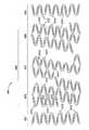
도 20 및 도 21은 본 발명의 하나의 양태에 따라 부분적으로 팽창된 상태의 스텐트(1100)의 평면도이다. 스텐트 구조는 일반적으로 근위 단부 및 원위 단부(1104,1105)들 각각을 따라 폐쇄된 환형의 근위 단부 섹션 및 폐쇄된 환형의 원위 단부 섹션(1106,1107)들과 이들 사이의 실질적인 나선형 내부 섹션(1108)을 포함한다, 스텐트(1100)는 원주방향으로 배향된 일련의 연성 힌지(1114)들에 의해 연결된, 길이방향으로 배향된 복수의 스트럿(1113)들을 포함한다. 원주방향으로 인접한 스트럿(1113)들은 대향 단부들에서 힌지(1114)에 의해 실질적으로 S자 또는 Z자 형상인 사인파형 패턴으로 연결되어 밴드를 형성한다. 가요성 커넥터(1112)들이 다양한 하중 조건하에서의 구조적 안정성을 위해 스텐트(1100) 구조의 전체에 걸쳐 분포되어 있다. 도 20 및 도 21에 도시된 스텐트 디자인은 어떤 하나의 가요성 커넥터 기하형태를 갖지만, 매우 다양한 커넥터 기하형태가 고려된다. 도 6b 내지 도 6h를 일반적으로 참조할 수 있다.Figures 20 and 21 are plan views of a partially expanded
구조적 피쳐(1120)는 내부 섹션(1108)을 따라 위치하여 나선형 패턴을 기능적으로 차단하여 나선형 내부 섹션(1108)을 두 개의 별도의 써브섹션(1108A) 및 (1108B)들로 효과적으로 분리시킨다. 도시된 양태에서, 구조적 피쳐(1120)는 구성요소 프로파일을 따르는 일치 지점(coincident point)에서 나선형 섹션(1108)의 나머지보다 더 넓은 구성요소를 갖는 나선형 밴드 구성요소(1120)를 포함한다. 일치 지점은 유사한 구성요소 상의 동일한 상대 지점일 것이다. 예를 들어, 나선형 밴드 구성요소(1120)에서 3-저장소 스트럿의 길이방향 길이를 따른 중간 지점에서의 스트럿 폭 측정치는 나선형 밴드 구성요소(1120)에 존재하지 않는 3-저장소 스트럿의 길이방향 길이에 따른 중간 지점에서의 스트럿 폭 측정치보다 더 넓을 것이다. 특히, 도시된 양태는 더 넓은 힌지(1114)들 및 스트럿(1113)들을 갖는 나선형 밴드 구성요소(1120)를 보여 주고 있지만, 더 넓은 힌지(1114)들 또는 스트럿(1113)들만을 갖는 나선형 밴드(1120)도 또한 본 발명에서 고려되고 있다. 나선형 밴드(1120)는 더 강성이며, 스텐트의 팽창성 및 가요성을 변화시킨다. 멤버들의 폭, 크기 및 형상은 스텐트를 "조정(tune)"하여, 바라는 특성들을 달성하도록 변경될 수 있다.The
제1 써브섹션(1108A)은 환형의 근위 섹션(1106)과 넓어진 나선형 밴드 구성요소(1120) 사이에 위치한다. 제2 나선형 써브섹션(1108B)은 환형의 원위 단부 섹션(1107)과 넓어진 나선형 밴드 구성요소(1120) 사이에 위치한다. 나선형 내부 섹션(1108)은 중심 구역(1111), 근위 전이 구역 및 원위 전이 구역(1109,1110)들 각각을 추가로 포함할 수 있다. 전이 구역(1109,1110)들은 중심 구역(1111)들과 환형의 근위 단부 섹션 및 환형의 원위 단부 섹션(1106,1107)들 각각의 사이에서 전이한다.
중심 구역(1111)은 스트링 패턴을 형성하도록 편성되는 근접한 스트럿 멤버(1113)들 및 힌지 멤버(1114)들의 그룹으로부터 형성된 스트링들(구성요소들의 집합체)을 포함할 수 있다. 본 발명의 하나의 양태에서, 근접한 스트링들은 상이한 스트링 패턴들을 가지며, 반복하는 스트링들 및 이 스트링들을 구성하는 구성요소들은 반복하는 중심 패턴을 형성하도록 기하학적으로 대칭이다. 본 발명의 바람직한 양태에서, 반복하는 중심 패턴은 2개의 상이한 반복 스트링들로 이루어진다. 중심 구역(1111)은 또한 넓어진 나선형 밴드 구성요소(1120)를 포함한다. 구조적 피쳐(1120)는 중심 구역(1111)에서 반복 패턴을 차단하는 반면, 스트럿들 및 힌지들의 남아있는 반복 패턴은 넓어진 나선형 밴드 구성요소(1120)의 앞과 뒤에서 계속된다.The
도 21은 본 발명의 하나의 양태에 따라 스텐트(1100)의 중심 구역(1111)을 형성하는 반복 패턴의 일부인 두 개의 스트럿 스트링들을 도시한 것이다. 중심 구역(1111)은 커넥터 스트럿 스트링을 갖는 근위 전이 구역(1109)의 원위 단부에서 시작한다. 도시된 커넥터 스트럿 스트링은 근위 및 원위 단부들에서의 커넥터 힌지(1114b), 및 자유 힌지(1114a)에 의해 연결된 3개의 긴(3-저장소) 스트럿(1113)들의 배열을 포함한다. 커넥터 스트럿 스트링을 따르는 자유 스트럿 스트링은 이의 근위 단부 상에서 커넥터 스트럿 스트링의 원위 단부에 부착된다. 도시된 자유 스트럿 스트링은 자유 힌지(1114a)에 의해 상호연결된 일련의 3개의 긴(3-저장소) 스트럿(1113)을 포함한다. 3개의 3-저장소 스트럿(1113)들은 각각의 단부에서 자유 힌지(1114a)에 의해 짧은 2-저장소 스트럿(1113)에 연결된다. 교호하는 커넥터 스트럿 스트링들 및 자유 스트럿 스트링들의 패턴은 스트링 패턴(1111)이 구조적 피쳐(1120) - 도시된 양태에서는 넓어진 나선형 밴드 구성요소(1120) - 를 만날 때까지 계속된다. 상기한 바와 같이, 스트링들 및 스트링 패턴들을 형성하는 구성요소들, 즉 스트럿들 및 힌지들은 유사 스트링들 및 스트링 패턴들의 보완 구성요소들과 일반적으로 크기와 형상이 균일하다. 그러나, 도 20 및 21에 도시된 구조적 피쳐(1120)는 이러한 패턴을 깨뜨린다. 도시된 양태의 구조적 피쳐(1120)가 중심 구역(1111)의 나머지와 동일한 스트럿 스트링들 및 패턴을 유지하는 반면, 구조적 피쳐(1120)는 선행 및 후행의 스트링들보다 더 넓은 스트럿들 및 힌지들로부터 형성된다. 이와 같이, 구조적 피쳐(1120)를 형성하는 구성요소들은 중심 구역(1111)의 나머지를 형성하는 구성요소들과 동일한 크기와 형상을 갖지 않는다. 반복 패턴은 구조적 피쳐(1120)(넓어진 나선형 밴드) 뒤에서 이 반복 패턴이 원위 전이 구역(1110)을 만날 때까지 계속된다.Figure 21 illustrates two strut strings that are part of a repeating pattern forming the
중심 구역에서 반복 패턴을 차단하는 구조적 피쳐의 또 다른 본 발명의 양태는 인접한 나선형 권선부들 사이에 부가적인 커넥터들을 갖는 섹션을 포함한다. 도 22 및 도 23은 본 발명의 하나의 이러한 양태에 따라 부분적으로 팽창된 상태의 스텐트(1200)의 평면도이다. 앞에서 기술된 스텐트들과 유사하게, 스텐트(1200)의 구조는 일반적으로 근위 단부 및 원위 단부(1204,1205)들 각각을 따라 폐쇄된 환형의 근위 단부 섹션 및 폐쇄된 환형의 원위 단부 섹션(1206,1207)들 각각과, 이들 사이의 실질적인 나선형 내부 섹션(1208)을 포함한다. 스텐트(1200)는 원주방향으로 배향된 일련의 연성 힌지(1214)들에 의해 연결된, 길이방향으로 배향된 복수의 스트럿(1213)들을 포함한다. 원주방향으로 인접한 스트럿(1213)들은 대향 단부들에서 힌지(1214)들에 의해 실질적으로 S자 또는 Z자 형상인 사인파형 패턴으로 연결되어 밴드를 형성한다. 가요성 커넥터(1212)들이 다양한 하중 조건하에서의 구조적 안정성을 위해 스텐트(1200) 구조 전체에 걸쳐 분포되어 있다. 부가적인 커넥터(1212)를 갖는 구조적 피쳐(1220)를 명백하게 설명하기 위해, 연결 영역들 및 연성 힌지들을 참조한다.Another aspect of the present invention of a structural feature that blocks repeating patterns in a central zone includes a section with additional connectors between adjacent helical turns. Figures 22 and 23 are plan views of a partially expanded
앞서서 기술된 스텐트들과 유사하게, 스텐트(1200)에는 두가지 타입의 연성 힌지(1214)들이 발견된다. 상기한 바와 같이, 도 5a 및 도 5b는 두 개의 전형적인 연성 힌지들을 도시한 것이다. 도 5a는 원주방향으로 인접한 2개의 스트럿(113)들을 연결하는, 본 양태의 자유 힌지(1214a)와 유사한 단일 "자유 힌지"(114a)를 도시한 것이다. 바람직한 양태에서, 이러한 자유 힌지(114a)는 "C"자 형상이며, 만곡된 섹션 상의 정점 지점을 통과하여 그어진 기준선 "A"에 대해 실질적으로 대칭이다. 도 5b는 원주방향으로 인접한 2개의 스트럿(113)들을 연결하는, 본 양태의 힌지(1214b)와 유사한 연성 힌지(114b)를 도시하고 있는데, 여기서 스트럿들 중 하나는 가요성 커넥터(112)에 추가로 연결된다. 이러한 연성 힌지(114b)는 형상이 도 5a에 개시된 "C"자 형상의 자유 힌지(114a)보다 더 원형이며, 때때로 본원에서 "원형 힌지"(114b)로서 지칭된다. 자유 힌지(1214a)들 및 커넥터 힌지(1214b)들이 여기에서는 별도로 구별되지만, 이들은 때때로 일반적으로 둘 다 연성 힌지(1214)들로 지칭된다. 원형 힌지(1214b)를 둘러싸는 영역들은 원형 힌지 영역으로 지칭된다. 가요성 커넥터(1212) 및 원형 연성 힌지(1214b)는 둘 다 원형 힌지 영역에서 스트럿(1213)의 동일한 짧은 변(116)에 연결되지만, 이들은 서로 연결되지는 않는다.Similar to the stents described above, two types of
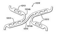
도 24는 나선형 섹션(1208)의 인접한 권선부들 상의 2개의 스트럿 쌍들 사이의 연결 지점으로서 작용하는 "원형 힌지 영역"(1218)을 더욱 상세하게 설명한 것이다. 이러한 힌지 영역(1218)은 수개의 컴포넌트들을 포함하며, 스트럿 쌍을 형성하는 원주방향으로 인접한 스트럿(1213)들 사이에 연성 영역을 제공하면서, 가요성 커넥터(1212)에 의해 길이방향으로 인접한 스트럿 쌍들 사이에 필요한 연결성을 제공한다. 조합될 때, 길이방향으로 인접한 스트럿 쌍들 및 상호연결되는 가요성 커넥터(1212)는 "쿼드(quad) 힌지 영역들"로 알려진 영역들을 생성한다. 이들 영역들은 원형 힌지(1214b)들 및 가요성 커넥터(1212)들을 통해 직접적으로 또는 간접적으로 연결되는 4개의 스트럿들로 구성된다. 붙임각, 힌지(1214b) 폭, 테이퍼링 정도, 길이 및 구멍 패턴은 스텐트들의 의도된 디자인, 피쳐의 위치 및 스텐트 성능 최적화에 근거하여 변화되기 쉽다. 도 6b 내지 도 6m은 원형 힌지 영역(1218)에서 인접한 스트럿 쌍들을 연결하기 위해 사용될 수 있는 다양한 커넥터들을 도시하였다. 이것은 구조적 피쳐(1220)를 확인하는데 사용될 수 있는 원주방향으로 인접한 힌지 영역(1218)들 사이의 개수 및 공간과 관련된다.Figure 24 illustrates in more detail the "circular hinge region" 1218, which acts as a point of connection between two strut pairs on adjacent turns of
구조적 피쳐(1220)는 내부 섹션(1208)을 따라 위치하여 나선형 패턴을 기능적 및 구조적으로 차단하여 나선형 내부 섹션(1208)을 두 개의 별도의 써브섹션(1208A) 및 (1208B)들로 효과적으로 분리시킨다. 도시된 양태에서, 구조적 피쳐(1220)는 나선형 내부 섹션(1208)의 나머지보다 더 많은 가요성 커넥터(1212), 즉 더 많은 원형 힌지 영역(1218)들을 갖는 나선형 밴드 구성요소를 포함한다. 즉, 힌지 영역(1218)들 사이의 개수 및 공간은 스텐트의 나머지에서보다 구조적 피쳐(1220) 영역에서 더 크다. 명확히 하기 위해, 더 조밀한 가요성 연결 기하형태를 갖는 구조적 피쳐(1220)를 형성하는 나선형 밴드 구성요소는 음영처리되었다. 특히, 도시된 양태는 원주배향으로 인접된 두 개의 스트럿 쌍마다 하나의 쌍에서 힌지 영역(1218)들 사이에 연결된 가요성 커넥터(1212)들을 갖는 구조적 피쳐(1220)를 보여 준다. 부가적인 가요성 커넥터(1212)는 구조적 피쳐(1220)를 스텐트(1200)의 나머지보다 더 강성으로 만들고, 스텐트의 팽창 및 가요성 특성들을 변화시킨다. 가요성 커넥터(1212)들의 개수 및 공간은 스텐트를 "조정"하여 원하는 특성들을 달성하도록 변경시킬 수 있다. 예를 들어, 스텐트는 또한 가요성 커넥터(1212)들이 모든 길이방향으로 인접한 스트럿 쌍 사이에서 연결되는 구조적 구성요소(1220)를 가질 수 있다.The
도 22 및 도 23을 다시 참조하자면, 제1 써브섹션(1208A)은 환형의 근위 섹션(1206)과 구조적 피쳐(1220) 사이에 위치한다. 제2 나선형 써브섹션(1208B)은 환형의 원위 단부 섹션(1207)과 구조적 피쳐(1220) 사이에 위치한다. 나선형 내부 섹션(1208)은 중심 구역(1211), 및 근위 전이 구역 및 원위 전이 구역(1209,1210)들 각각을 추가로 포함할 수 있다. 전이 구역(1209,1210)들은 중심 구역(1211)들과 각각의 환형의 근위 단부 섹션 및 환형의 원위 단부 섹션(1206,1207)들 사이에서 전이한다.Referring again to Figs. 22 and 23, the
중심 구역(1211)은 스트링 패턴을 형성하도록 편성되는 근접한 스트럿 멤버(1213)들 및 힌지 멤버(1214)들의 그룹으로부터 형성된 스트링들(구성요소들의 집합체)을 포함할 수 있다. 본 발명의 하나의 양태에서, 근접한 스트링들은 상이한 스트링 패턴들을 가지며, 반복하는 스트링들 및 이 스트링들을 구성하는 구성요소들은 반복하는 중심 패턴을 형성하도록 기하학적으로 대칭이다. 본 발명의 바람직한 양태에서, 반복하는 중심 패턴은 2개의 상이한 반복 스트링들로 이루어진다. 중심 구역(1211)은 또한 더 조밀한 원형의 힌지 영역(1218)을 갖는 구조적 피쳐(1220)를 포함한다. 구조적 피쳐(1220)는 중심 구역(1211)에서 반복 패턴을 차단하고 스트럿들 및 힌지들의 반복 패턴은 구조적 피쳐(1220)의 앞과 뒤에 존재한다.The
도 23은 본 발명의 하나의 양태에 따라 스텐트(1200)의 중심 구역(1211)을 형성하는 반복 패턴의 일부인 스트럿 스트링들을 도시한 것이다. 중심 구역(1211)은 일반적으로 파형 패턴이 나선형 중심 구역(1211) 전체에 걸쳐 권선되기 때문에 힌지(1214)에 의해 연결된 길이방향으로 인접한 스트럿(1213)들 쌍들에 의해 형성된 매 4번째의 굽힘부(bend) 또는 파형부에 부착된 커넥터(1212) 또는 힌지 영역(1218)을 포함한다. 즉, 상기 패턴에서 커넥터 힌지(1214b)에 이어서 3개의 자유 힌지가 이어진다. 그러나, 도 22 및 23에서 명확히 하기 위해 음영처리된 구조적 피쳐(1220)는 두 개의 파형마다 하나의 파형에 힌지 영역을 가졌으며, 나선형 패턴은 중심 구역(1211)을 통하여 권선된다. 커넥터 힌지(1214b)에 이어서 3개의 자유 힌지(1214a)들의 반복 패턴은 구조적 피쳐(1120) 뒤에서 반복 패턴이 원위 전이 구역(1210)을 만날 때까지 계속된다. 중심 구역(1211)을 형성하는 비차단된 반복 패턴을 가장 잘 도시하기 위하여 중심 구역(1211)의 원위 단부에서 시작하는 패턴을 따랐다. 중심 구역(1211)의 원위 단부는 커넥터 스트럿 스트링으로 시작된다. 도시된 커넥터 스트럿 스트링은 이의 근위 및 원위 단부들에서의 커넥터 힌지(1214b), 및 자유 힌지(1214a)에 의해 연결된 3개의 긴(3-저장소) 스트럿(1213)들의 배열을 포함한다. 근위 방향으로 권선될 때 커넥터 스트럿 스트링을 따르는 자유 스트럿 스트링은 이것의 원위 단부 상에서 커넥터 스트럿 스트링의 근위 단부에 부착된다. 도시된 자유 스트럿 스트링은 자유 힌지(1214a)에 의해 상호연결된 일련의 3개의 긴(3-저장소) 스트럿(1213)들을 포함한다. 3개의 3-저장소 스트럿(1213)들은 각각의 단부에서 자유 힌지(1214a)들에 의해 짧은 2-저장소 스트럿(1213)들에 연결된다.23 depicts strut strings that are part of a repeating pattern forming the
도 22 및 도 23에 도시된 양태는 길이방향 축에 대하여 모두 동일한 방향으로 배향되는 구조적 피쳐(1220)에서의 커넥터(1212)들을 도시한 것이다. 즉, 원위에서 근위 방향으로 움직일 때, 모든 커넥터(1212)들은 스트럿(1213)의 하부 단부 부분에서부터 길이방향으로 인접한 스트럿(1213)의 상부 부분으로 연결된다. 각각의 커넥터(1212)에 걸쳐 그어진 가상의 선이 길이방향 축에 평행한 라인과 예각을 형성할 것이다.22 and 23 illustrate
본 발명의 또 다른 양태에서는 일부 패턴에서 커넥터(1212)의 방향이 교호하는 것을 고려하고 있다. 도 25 및 도 26은 본 발명의 이러한 양태에 따라 부분적으로 팽창된 상태의 스텐트(1300)의 평면도이다. 상기한 스텐트(1200)와 유사하게, 스텐트(1300) 구조는 일반적으로 근위 단부 및 원위 단부(1304,1305)들 각각을 따라 폐쇄된 환형의 근위 단부 섹션 및 폐쇄된 환형의 원위 단부 섹션(1306,1307)들 각각과, 이들 사이의 실질적인 나선형 내부 섹션(1308)을 포함한다, 스텐트(1300)는 원주방향으로 배향된 일련의 연성 힌지(1314)들에 의해 연결된, 길이방향으로 배향된 복수의 스트럿(1313)들을 포함한다. 원주방향으로 인접한 스트럿(1313)들은 대향 단부들에서 힌지(1314)들에 의해 실질적으로 S자 또는 Z자 형상인 사인파형 패턴으로 연결되어 밴드를 형성한다. 가요성 커넥터(1312)들이 다양한 하중 조건하에서의 구조적 안정성을 위해 스텐트(1200) 구조의 전체에 걸쳐 분포되어 있다.In yet another aspect of the present invention, it is contemplated that the orientation of
또한, 스텐트(1300)는 명확히 하기 위해 음영처리된 구조적 피쳐(1320)를 갖는데, 이것은 중심 구역(1311)의 인접한 나선형 권선부들 사이의 부가적인 커넥터들을 포함한다. 그러나, 모든 커넥터(1212)들이 동일 방향으로 배향되는, 스텐트(1200)에서의 구조적 피쳐(1220)를 형성하는 커넥터(1212)들의 조밀한 밴드와는 다르게, 스텐트(1300)에서의 커넥터(1312)들의 밴드(1320)는 교호하는 배향을 갖는다. 즉, 원주방향으로 인접한 커넥터(1312)들은 길이방향 축과의 예각 내지는 길이방향 축과의 둔각을 형성하는 것 사이에서 교호한다. 커넥터(1312)들이 대향 배향되면 필요 시에 부가적인 전단 강화가 제공된다.The
중심 구역에서 반복 패턴을 차단시키는 구조적 피쳐의 또 다른 본 발명의 양태에서는 상기한 환형의 단부 섹션들과 유사하게 환형의 중심 섹션 형태의 구조적 피쳐를 포함한다. 도 27 및 도 28은 이러한 피쳐를 포함하는 본 발명의 하나의 양태에 따라 부분적으로 팽창된 상태의 스텐트(1400)의 평면도이다.Another aspect of the present invention of a structural feature that blocks repeating patterns in a central zone includes structural features in the form of an annular center section similar to the annular end sections described above. Figures 27 and 28 are plan views of a partially expanded
스텐트(1400)의 구조는 일반적으로 근위 단부 및 원위 단부(1404,1405)들 각각을 따라 폐쇄된 환형의 근위 단부 섹션 및 폐쇄된 환형의 원위 단부 섹션(1406,1407)들 각각과, 이들 사이에 위치한 환형의 중심 섹션(1420)을 포함한다. 환형 섹션(1406,1407,1420)들은 축상 배열 면에서 폐쇄된 후프 구조이며, 길이방향 축을 한정한다. 예시된 양태가 각 위치에서 하나의 환형 구조를 보이지만, 환형 섹션들 사이의 개수 및 상대 공간이 본 스텐트 디자인에서 제한되는 구성요소로서 해석되어서는 안된다.The structure of the
스텐트(1400)는 환형 섹션들 사이에 적어도 두 개의 나선형 섹션들을 추가로 포함한다. 도시된 양태에서, 제1 나선형 섹션(1408A)은 환형의 근위 단부 섹션(1406)과 환형의 중심 섹션(1420) 사이에 위치한다. 제2 나선형 섹션(1408B)은 환형의 원위 단부 섹션(1407)과 환형의 중심 섹션(1420) 사이에 위치한다. 나선형 내부 섹션(1408A,1408B)들은 각각 중심 구역과 근위 전이 구역과 원위 전이 구역을 추가로 포함할 수 있다.The
도 28은 각각의 나선형 섹션에서 중심 및 전이 섹션들을 도시하는 스텐트(1400)의 분해 평면도이다. 특히, 나선형 내부 섹션(1408A)은 중심 구역(1411A), 근위 전이 구역 및 원위 전이 구역(1409A,1410A)들 각각을 포함한다. 유사하게는, 나선형 내부 섹션(1418B)은 중심 구역(1411B), 근위 전이 구역 및 원위 전이 구역(1409B,1410B)들 각각을 포함한다. 전이 구역(1409A,1409B)들은 나선형 패턴을 중심 구역(1411A,1411B)들 각각과 환형의 근위 단부 섹션 및 환형의 원위 단부 섹션(1406,1407)들 각각의 사이에서 전이한다. 전이 구역(1410A,1410B)들은 나선형 패턴을 중심 구역(1411A,1411B)들과 환형의 중심 섹션(1420) 사이에서 전이한다.28 is an exploded plan view of the
스텐트(1400)는 원주방향으로 배향된 일련의 연성 힌지(1414)들에 의해 연결된, 길이방향으로 배향된 복수의 스트럿(1413)들을 포함한다. 원주방향으로 인접한 스트럿(1413)들은 대향 단부들에서 힌지(1414)들에 의해 실질적으로 S자 또는 Z자 형상인 사인파형 패턴으로 연결되어 밴드를 형성한다. 환형의 단부 섹션(1406,1407)들 및 구조적 피쳐(1420)를 형성하는 밴드는 폐쇄된 환이다. 나선형 중심 섹션(1408A,1408B)들을 형성하는 밴드들은 길이방향 축 둘레로 소용돌이형 또는 나선형 방식으로 권선된다. 가요성 커넥터(1412)들은 다양한 하중 조건하에서의 구조적 안정성을 위해 스텐트(1400) 구조의 전체에 걸쳐 분포된다. 도 27 및 도 28에 도시된 스텐트 디자인은 어떤 하나의 가요성 커넥터 기하형태를 갖지만, 매우 다양한 커넥터 기하형태들이 고려된다. 일반적으로 도 6b 내지 도 6h를 참조한다.The
중심 구역(1411A,1411B)들은 스트링 패턴을 형성하도록 편성되는 근접한 스트럿 멤버(1413)들 및 힌지 멤버(1414)들의 그룹으로부터 형성된 스트링들(구성요소들의 집합체)을 포함할 수 있다. 본 발명의 하나의 양태에서, 근접한 스트링들은 상이한 스트링 패턴들을 가지며, 반복하는 스트링들 및 이 스트링들을 구성하는 구성요소들은 반복하는 중심 패턴을 형성하도록 기하학적으로 대칭이다. 본 발명의 바람직한 양태에서, 반복하는 중심 패턴은 2개의 상이한 반복 스트링들로 이루어진다.
도 28은 본 발명의 하나의 양태에 따라 스텐트(1400)의 중심 구역(1411A,1411B)들을 형성하는 반복 패턴의 일부인 스트럿 스트링들을 도시한 것이다. 중심 구역(1411)을 형성하는 비차단된 반복 패턴을 가장 잘 도시하기 위해 중심 구역(1411B)의 원위 단부에서 시작하는 패턴을 따랐다. 중심 구역(1411B)의 원위 단부는 커넥터 스트럿 스트링으로 시작된다. 도시된 커넥터 스트럿 스트링은 이의 근위 및 원위 단부에서의 커넥터 힌지(1414b) 및 자유 힌지(1414a)들에 의해 연결된 3개의 긴(3-저장소) 스트럿(1413)들의 배열을 포함한다. 근위 방향으로 권선될 때 커넥터 스트럿 스트링을 따르는 자유 스트럿 스트링은 이의 원위 단부 상에서 커넥터 스트럿 스트링의 근위 단부에 부착된다. 도시된 자유 스트럿 스트링은 자유 힌지(1414a)에 의해 상호연결된 일련의 3개의 긴(3-저장소) 스트럿(1413)들을 포함한다. 3개의 3-저장소 스트럿(1413)은 각각의 단부에서 자유 힌지(1414a)들에 의해 짧은 2-저장소 스트럿(1413)에 연결된다. 유사한 패턴이 중심 구역(1411A)에서 발견된다. 스트럿 스트링들의 패턴은 중심 구역(1411A,1411B)들 전체에 걸쳐서 반복된다.Figure 28 illustrates strut strings that are part of a repeating pattern forming
구조적 피쳐(1420)를 형성하는 폐쇄된 환은 더욱 강성의 중심 지역을 제공하여서 스텐트가 팽창된 풍선에 더욱 확고하게 크림핑되게 한다. 이것은 스텐트 전개를 개선시킬 것이다. 이러한 디자인은 전개 동안에 전방으로 길어지는 위험성을 또한 감소시켜서 스텐트의 의도하지 않은 변형을 감소시키고, 더 큰 파쇄 저항성을 산출하고, 의도하는 스텐트 길이를 유지시킴으로써 스텐트의 배치에 일반적으로 도움을 줄 것이다.
The closed ring that forms the
Claims (1)
Translated fromKorean상기 관형 가요성 스텐트는 근위 단부 부분(proximal end portion)과 원위 단부 부분(distal end portion)을 갖고, 내강 표면(luminal surface) 및 내강으로부터 벗어난 표면(abluminal surface)과 이들 사이의 두께를 갖는 원통형 형상(여기서, 상기 원통형 형상은 길이방향 축을 한정한다)을 가지며,
상기 관형 가요성 스텐트는, 근위 나선형 섹션, 원위 나선형 섹션, 및 이들 사이의 중간 환 섹션(intermediate ring section)을 포함하고, 상기 근위 나선형 섹션과 원위 나선형 섹션 각각은, 길이방향으로 배향된 복수의 스트럿 멤버(strut member)들, 및 원주방향으로 인접한 스트럿 멤버들을 밴드를 형성하도록 연결하는 원주방향으로 배향된 복수의 힌지 멤버들을 가지며, 상기 밴드는 실질적으로 나선형 방식으로 상기 길이방향 축 둘레로 말아져서(wrapped) 복수의 나선형 권선부(winding)들을 형성하며, 상기 중간 환 섹션은 길이방향으로 배향된 복수의 스트럿 멤버들, 및 원주방향으로 인접한 스트럿 멤버들을 엔드리스 환(endless ring)을 형성하도록 연결하는 원주방향으로 배향된 복수의 힌지 멤버들을 포함하며, 상기 중간 환 섹션은 적어도 하나의 커넥터 멤버(connector member)들에 의해 상기 근위 나선형 섹션의 상기 원위 단부 및 상기 원위 나선형 섹션의 상기 근위 단부에 부착되어 있는,
관형 가요성 스텐트.As a tubular flexible stent,
The tubular flexible stent has a proximal end portion and a distal end portion and has a cylindrical shape with an abluminal surface and a thickness between the luminal surface and the lumen, (Where the cylindrical shape defines a longitudinal axis)
Wherein the tubular flexible stent includes a proximal spiral section, a distal spiral section, and an intermediate ring section therebetween, each of the proximal spiral section and the distal spiral section having a plurality of longitudinally oriented struts Strut members and a plurality of circumferentially oriented hinge members connecting circumferentially adjacent strut members to form a band, said band being curled about said longitudinal axis in a substantially helical fashion wherein the intermediate ring section comprises a plurality of longitudinally oriented strut members and a plurality of circumferentially adjacent strut members for connecting the circumferentially adjacent strut members to form an endless ring, Wherein the intermediate ring section comprises at least one connector member (conne < RTI ID = 0.0 > cortical members attached to said proximal end of said proximal spiral section and said proximal end of said distal spiral section,
Tubular flexible stent.
Applications Claiming Priority (3)
| Application Number | Priority Date | Filing Date | Title |
|---|---|---|---|
| US36996210P | 2010-08-02 | 2010-08-02 | |
| US61/369,962 | 2010-08-02 | ||
| PCT/US2011/046299WO2012018840A1 (en) | 2010-08-02 | 2011-08-02 | Flexible helical stent having intermediated non-helical region |
Related Parent Applications (1)
| Application Number | Title | Priority Date | Filing Date |
|---|---|---|---|
| KR1020137005474ADivisionKR20130096716A (en) | 2010-08-02 | 2011-08-02 | Flexible helical stent having intermediated non-helical region |
Publications (2)
| Publication Number | Publication Date |
|---|---|
| KR20160103150Atrue KR20160103150A (en) | 2016-08-31 |
| KR101961531B1 KR101961531B1 (en) | 2019-07-17 |
Family
ID=44533145
Family Applications (2)
| Application Number | Title | Priority Date | Filing Date |
|---|---|---|---|
| KR1020137005474ACeasedKR20130096716A (en) | 2010-08-02 | 2011-08-02 | Flexible helical stent having intermediated non-helical region |
| KR1020167022605AExpired - Fee RelatedKR101961531B1 (en) | 2010-08-02 | 2011-08-02 | A tubular flexible stent having helical sections |
Family Applications Before (1)
| Application Number | Title | Priority Date | Filing Date |
|---|---|---|---|
| KR1020137005474ACeasedKR20130096716A (en) | 2010-08-02 | 2011-08-02 | Flexible helical stent having intermediated non-helical region |
Country Status (11)
| Country | Link |
|---|---|
| US (1) | US10231855B2 (en) |
| EP (1) | EP2600803B1 (en) |
| JP (1) | JP5914479B2 (en) |
| KR (2) | KR20130096716A (en) |
| CN (1) | CN103118639B (en) |
| AU (1) | AU2011285808B2 (en) |
| BR (1) | BR112013002720A2 (en) |
| CA (1) | CA2807025C (en) |
| IL (1) | IL224233A (en) |
| MX (1) | MX2013001443A (en) |
| WO (1) | WO2012018840A1 (en) |
Families Citing this family (2)
| Publication number | Priority date | Publication date | Assignee | Title |
|---|---|---|---|---|
| MX2013001444A (en)* | 2010-08-02 | 2013-03-12 | Cordis Corp | Flexible helical stent having different helical regions. |
| WO2025086189A1 (en)* | 2023-10-26 | 2025-05-01 | Covidien Lp | Stent with struts defining circumferentially offset apices |
Citations (4)
| Publication number | Priority date | Publication date | Assignee | Title |
|---|---|---|---|---|
| US5810872A (en)* | 1997-03-14 | 1998-09-22 | Kanesaka; Nozomu | Flexible stent |
| US20040249449A1 (en)* | 2003-06-05 | 2004-12-09 | Conor Medsystems, Inc. | Drug delivery device and method for bi-directional drug delivery |
| US20070005126A1 (en)* | 2005-06-30 | 2007-01-04 | Boston Scientific Scimed, Inc. | Hybrid stent |
| US20080097582A1 (en)* | 2006-10-18 | 2008-04-24 | Conor Medsystems, Inc. | Stent with flexible hinges |
Family Cites Families (57)
| Publication number | Priority date | Publication date | Assignee | Title |
|---|---|---|---|---|
| US4733665C2 (en) | 1985-11-07 | 2002-01-29 | Expandable Grafts Partnership | Expandable intraluminal graft and method and apparatus for implanting an expandable intraluminal graft |
| US5102417A (en) | 1985-11-07 | 1992-04-07 | Expandable Grafts Partnership | Expandable intraluminal graft, and method and apparatus for implanting an expandable intraluminal graft |
| SE453258B (en) | 1986-04-21 | 1988-01-25 | Medinvent Sa | ELASTIC, SELF-EXPANDING PROTEST AND PROCEDURE FOR ITS MANUFACTURING |
| US4969458A (en) | 1987-07-06 | 1990-11-13 | Medtronic, Inc. | Intracoronary stent and method of simultaneous angioplasty and stent implant |
| US5507767A (en) | 1992-01-15 | 1996-04-16 | Cook Incorporated | Spiral stent |
| US5913897A (en) | 1993-09-16 | 1999-06-22 | Cordis Corporation | Endoprosthesis having multiple bridging junctions and procedure |
| DE69528216T2 (en) | 1994-06-17 | 2003-04-17 | Terumo K.K., Tokio/Tokyo | Process for the production of a permanent stent |
| BE1009278A3 (en) | 1995-04-12 | 1997-01-07 | Corvita Europ | Guardian self-expandable medical device introduced in cavite body, and medical device with a stake as. |
| US5922021A (en) | 1996-04-26 | 1999-07-13 | Jang; G. David | Intravascular stent |
| JP4636634B2 (en) | 1996-04-26 | 2011-02-23 | ボストン サイエンティフィック サイムド,インコーポレイテッド | Intravascular stent |
| US20040225347A1 (en) | 2000-06-05 | 2004-11-11 | Lang G. David | Intravascular stent with increasing coating retaining capacity |
| US20040106985A1 (en) | 1996-04-26 | 2004-06-03 | Jang G. David | Intravascular stent |
| US6783543B2 (en) | 2000-06-05 | 2004-08-31 | Scimed Life Systems, Inc. | Intravascular stent with increasing coating retaining capacity |
| US20020058990A1 (en) | 2000-09-23 | 2002-05-16 | Jang G. David | Intravascular stent consists of stairstep expansion strut pairs and double stairstep diagonal connecting struts contralaterally extended from expansion struts |
| US6488706B1 (en) | 1996-05-08 | 2002-12-03 | Carag Ag | Device for plugging an opening such as in a wall of a hollow or tubular organ |
| US7070590B1 (en) | 1996-07-02 | 2006-07-04 | Massachusetts Institute Of Technology | Microchip drug delivery devices |
| US5827321A (en) | 1997-02-07 | 1998-10-27 | Cornerstone Devices, Inc. | Non-Foreshortening intraluminal prosthesis |
| US20040267350A1 (en) | 2002-10-30 | 2004-12-30 | Roubin Gary S. | Non-foreshortening intraluminal prosthesis |
| US6033433A (en) | 1997-04-25 | 2000-03-07 | Scimed Life Systems, Inc. | Stent configurations including spirals |
| US7329277B2 (en) | 1997-06-13 | 2008-02-12 | Orbusneich Medical, Inc. | Stent having helical elements |
| US6059822A (en) | 1997-08-22 | 2000-05-09 | Uni-Cath Inc. | Stent with different mesh patterns |
| US6190406B1 (en)* | 1998-01-09 | 2001-02-20 | Nitinal Development Corporation | Intravascular stent having tapered struts |
| US5938697A (en) | 1998-03-04 | 1999-08-17 | Scimed Life Systems, Inc. | Stent having variable properties |
| US7208010B2 (en)* | 2000-10-16 | 2007-04-24 | Conor Medsystems, Inc. | Expandable medical device for delivery of beneficial agent |
| DE19829701C1 (en) | 1998-07-03 | 2000-03-16 | Heraeus Gmbh W C | Radially expandable support device IV |
| US5911754A (en) | 1998-07-24 | 1999-06-15 | Uni-Cath Inc. | Flexible stent with effective strut and connector patterns |
| US6193744B1 (en) | 1998-09-10 | 2001-02-27 | Scimed Life Systems, Inc. | Stent configurations |
| US6042597A (en) | 1998-10-23 | 2000-03-28 | Scimed Life Systems, Inc. | Helical stent design |
| US6355059B1 (en)* | 1998-12-03 | 2002-03-12 | Medinol, Ltd. | Serpentine coiled ladder stent |
| US6096072A (en) | 1999-01-26 | 2000-08-01 | Uni-Cath Inc. | Self-exchange stent with effective supporting ability |
| US6730116B1 (en)* | 1999-04-16 | 2004-05-04 | Medtronic, Inc. | Medical device for intraluminal endovascular stenting |
| US6245101B1 (en) | 1999-05-03 | 2001-06-12 | William J. Drasler | Intravascular hinge stent |
| FR2793673B1 (en)* | 1999-05-18 | 2001-10-12 | Jean Marie Lefebvre | TUBULAR STENT TYPE WITH LOW CRUSHING RESISTANCE |
| US6569193B1 (en) | 1999-07-22 | 2003-05-27 | Advanced Cardiovascular Systems, Inc. | Tapered self-expanding stent |
| AU770395B2 (en) | 1999-11-17 | 2004-02-19 | Boston Scientific Limited | Microfabricated devices for the delivery of molecules into a carrier fluid |
| US6352552B1 (en) | 2000-05-02 | 2002-03-05 | Scion Cardio-Vascular, Inc. | Stent |
| US6423091B1 (en) | 2000-05-16 | 2002-07-23 | Cordis Corporation | Helical stent having flat ends |
| JP2003533335A (en) | 2000-05-22 | 2003-11-11 | オーバス メディカル テクノロジーズ インク. | Self-expanding stent |
| US6652576B1 (en) | 2000-06-07 | 2003-11-25 | Advanced Cardiovascular Systems, Inc. | Variable stiffness stent |
| US7766956B2 (en) | 2000-09-22 | 2010-08-03 | Boston Scientific Scimed, Inc. | Intravascular stent and assembly |
| JP2004521720A (en) | 2000-12-11 | 2004-07-22 | オーバス メディカル テクノロジーズ インク. | Stent with helical component |
| US6969402B2 (en) | 2002-07-26 | 2005-11-29 | Syntheon, Llc | Helical stent having flexible transition zone |
| US6878162B2 (en) | 2002-08-30 | 2005-04-12 | Edwards Lifesciences Ag | Helical stent having improved flexibility and expandability |
| DE10261822A1 (en)* | 2002-12-20 | 2004-07-01 | Biotronik Meß- und Therapiegeräte GmbH & Co. Ingenieurbüro Berlin | Helix bridge connection |
| US20050033410A1 (en) | 2002-12-24 | 2005-02-10 | Novostent Corporation | Vascular prothesis having flexible configuration |
| US20070239251A1 (en)* | 2002-12-31 | 2007-10-11 | Abbott Cardiovascular Systems Inc. | Flexible stent |
| US7163555B2 (en) | 2003-04-08 | 2007-01-16 | Medtronic Vascular, Inc. | Drug-eluting stent for controlled drug delivery |
| DE102006017873A1 (en)* | 2005-07-14 | 2007-01-25 | Qualimed Innovative Medizinprodukte Gmbh | Temporary stent |
| US8956400B2 (en) | 2005-10-14 | 2015-02-17 | Flexible Stenting Solutions, Inc. | Helical stent |
| GB0616999D0 (en) | 2006-08-29 | 2006-10-04 | Angiomed Ag | Annular mesh |
| US8545545B2 (en) | 2006-10-18 | 2013-10-01 | Innovational Holdings Llc | Stent with flexible hinges |
| EP2086599A4 (en)* | 2006-10-20 | 2012-11-28 | Orbusneich Medical Inc | Bioabsorbable medical device with coating |
| US8691321B2 (en)* | 2006-10-20 | 2014-04-08 | Orbusneich Medical, Inc. | Bioabsorbable polymeric composition and medical device background |
| US7722661B2 (en) | 2007-12-19 | 2010-05-25 | Boston Scientific Scimed, Inc. | Stent |
| US7972373B2 (en)* | 2007-12-19 | 2011-07-05 | Advanced Technologies And Regenerative Medicine, Llc | Balloon expandable bioabsorbable stent with a single stress concentration region interconnecting adjacent struts |
| US9060889B2 (en)* | 2009-09-18 | 2015-06-23 | Medtronic Vascular, Inc. | Methods for forming an orthogonal end on a helical stent |
| US8801775B2 (en)* | 2010-04-27 | 2014-08-12 | Medtronic Vascular, Inc. | Helical stent with opposing and/or alternating pitch angles |
- 2011
- 2011-08-02CACA2807025Apatent/CA2807025C/enactiveActive
- 2011-08-02WOPCT/US2011/046299patent/WO2012018840A1/enactiveApplication Filing
- 2011-08-02USUS13/196,462patent/US10231855B2/enactiveActive
- 2011-08-02AUAU2011285808Apatent/AU2011285808B2/ennot_activeCeased
- 2011-08-02CNCN201180047911.4Apatent/CN103118639B/ennot_activeExpired - Fee Related
- 2011-08-02MXMX2013001443Apatent/MX2013001443A/enactiveIP Right Grant
- 2011-08-02KRKR1020137005474Apatent/KR20130096716A/ennot_activeCeased
- 2011-08-02JPJP2013523283Apatent/JP5914479B2/enactiveActive
- 2011-08-02KRKR1020167022605Apatent/KR101961531B1/ennot_activeExpired - Fee Related
- 2011-08-02BRBR112013002720Apatent/BR112013002720A2/ennot_activeApplication Discontinuation
- 2011-08-02EPEP11743732.7Apatent/EP2600803B1/enactiveActive
- 2013
- 2013-01-15ILIL224233Apatent/IL224233A/enactiveIP Right Grant
Patent Citations (4)
| Publication number | Priority date | Publication date | Assignee | Title |
|---|---|---|---|---|
| US5810872A (en)* | 1997-03-14 | 1998-09-22 | Kanesaka; Nozomu | Flexible stent |
| US20040249449A1 (en)* | 2003-06-05 | 2004-12-09 | Conor Medsystems, Inc. | Drug delivery device and method for bi-directional drug delivery |
| US20070005126A1 (en)* | 2005-06-30 | 2007-01-04 | Boston Scientific Scimed, Inc. | Hybrid stent |
| US20080097582A1 (en)* | 2006-10-18 | 2008-04-24 | Conor Medsystems, Inc. | Stent with flexible hinges |
Also Published As
| Publication number | Publication date |
|---|---|
| CA2807025A1 (en) | 2012-02-09 |
| US10231855B2 (en) | 2019-03-19 |
| BR112013002720A2 (en) | 2016-05-31 |
| CN103118639A (en) | 2013-05-22 |
| CN103118639B (en) | 2016-11-09 |
| EP2600803A1 (en) | 2013-06-12 |
| IL224233A (en) | 2017-01-31 |
| AU2011285808B2 (en) | 2015-04-30 |
| KR101961531B1 (en) | 2019-07-17 |
| US20120029621A1 (en) | 2012-02-02 |
| JP2013535290A (en) | 2013-09-12 |
| MX2013001443A (en) | 2013-03-12 |
| EP2600803B1 (en) | 2022-05-18 |
| AU2011285808A1 (en) | 2013-02-07 |
| KR20130096716A (en) | 2013-08-30 |
| WO2012018840A1 (en) | 2012-02-09 |
| CA2807025C (en) | 2017-01-24 |
| JP5914479B2 (en) | 2016-05-11 |
Similar Documents
| Publication | Publication Date | Title |
|---|---|---|
| KR101774474B1 (en) | Flexible stent design | |
| KR101644410B1 (en) | Flexible helical stent having intermediate structural feature | |
| KR20160103151A (en) | Flexible helical stent having different helical regions | |
| US8920489B2 (en) | Flexible stent having protruding hinges | |
| KR101676265B1 (en) | Flexible helical stent having intermediate structural feature | |
| KR101961531B1 (en) | A tubular flexible stent having helical sections |
Legal Events
| Date | Code | Title | Description |
|---|---|---|---|
| A107 | Divisional application of patent | ||
| PA0104 | Divisional application for international application | St.27 status event code:A-0-1-A10-A16-div-PA0104 St.27 status event code:A-0-1-A10-A18-div-PA0104 | |
| PG1501 | Laying open of application | St.27 status event code:A-1-1-Q10-Q12-nap-PG1501 | |
| PA0201 | Request for examination | St.27 status event code:A-1-2-D10-D11-exm-PA0201 | |
| T11-X000 | Administrative time limit extension requested | St.27 status event code:U-3-3-T10-T11-oth-X000 | |
| T11-X000 | Administrative time limit extension requested | St.27 status event code:U-3-3-T10-T11-oth-X000 | |
| T11-X000 | Administrative time limit extension requested | St.27 status event code:U-3-3-T10-T11-oth-X000 | |
| T11-X000 | Administrative time limit extension requested | St.27 status event code:U-3-3-T10-T11-oth-X000 | |
| P11-X000 | Amendment of application requested | St.27 status event code:A-2-2-P10-P11-nap-X000 | |
| P13-X000 | Application amended | St.27 status event code:A-2-2-P10-P13-nap-X000 | |
| E902 | Notification of reason for refusal | ||
| PE0902 | Notice of grounds for rejection | St.27 status event code:A-1-2-D10-D21-exm-PE0902 | |
| T11-X000 | Administrative time limit extension requested | St.27 status event code:U-3-3-T10-T11-oth-X000 | |
| R17-X000 | Change to representative recorded | St.27 status event code:A-3-3-R10-R17-oth-X000 | |
| T11-X000 | Administrative time limit extension requested | St.27 status event code:U-3-3-T10-T11-oth-X000 | |
| T11-X000 | Administrative time limit extension requested | St.27 status event code:U-3-3-T10-T11-oth-X000 | |
| T11-X000 | Administrative time limit extension requested | St.27 status event code:U-3-3-T10-T11-oth-X000 | |
| T11-X000 | Administrative time limit extension requested | St.27 status event code:U-3-3-T10-T11-oth-X000 | |
| T13-X000 | Administrative time limit extension granted | St.27 status event code:U-3-3-T10-T13-oth-X000 | |
| T11-X000 | Administrative time limit extension requested | St.27 status event code:U-3-3-T10-T11-oth-X000 | |
| T13-X000 | Administrative time limit extension granted | St.27 status event code:U-3-3-T10-T13-oth-X000 | |
| T11-X000 | Administrative time limit extension requested | St.27 status event code:U-3-3-T10-T11-oth-X000 | |
| T13-X000 | Administrative time limit extension granted | St.27 status event code:U-3-3-T10-T13-oth-X000 | |
| T11-X000 | Administrative time limit extension requested | St.27 status event code:U-3-3-T10-T11-oth-X000 | |
| T13-X000 | Administrative time limit extension granted | St.27 status event code:U-3-3-T10-T13-oth-X000 | |
| T11-X000 | Administrative time limit extension requested | St.27 status event code:U-3-3-T10-T11-oth-X000 | |
| T13-X000 | Administrative time limit extension granted | St.27 status event code:U-3-3-T10-T13-oth-X000 | |
| T11-X000 | Administrative time limit extension requested | St.27 status event code:U-3-3-T10-T11-oth-X000 | |
| T13-X000 | Administrative time limit extension granted | St.27 status event code:U-3-3-T10-T13-oth-X000 | |
| T11-X000 | Administrative time limit extension requested | St.27 status event code:U-3-3-T10-T11-oth-X000 | |
| T13-X000 | Administrative time limit extension granted | St.27 status event code:U-3-3-T10-T13-oth-X000 | |
| AMND | Amendment | ||
| P11-X000 | Amendment of application requested | St.27 status event code:A-2-2-P10-P11-nap-X000 | |
| P13-X000 | Application amended | St.27 status event code:A-2-2-P10-P13-nap-X000 | |
| E601 | Decision to refuse application | ||
| PE0601 | Decision on rejection of patent | St.27 status event code:N-2-6-B10-B15-exm-PE0601 | |
| T11-X000 | Administrative time limit extension requested | St.27 status event code:U-3-3-T10-T11-oth-X000 | |
| T13-X000 | Administrative time limit extension granted | St.27 status event code:U-3-3-T10-T13-oth-X000 | |
| T11-X000 | Administrative time limit extension requested | St.27 status event code:U-3-3-T10-T11-oth-X000 | |
| T13-X000 | Administrative time limit extension granted | St.27 status event code:U-3-3-T10-T13-oth-X000 | |
| AMND | Amendment | ||
| P11-X000 | Amendment of application requested | St.27 status event code:A-2-2-P10-P11-nap-X000 | |
| P13-X000 | Application amended | St.27 status event code:A-2-2-P10-P13-nap-X000 | |
| PX0901 | Re-examination | St.27 status event code:A-2-3-E10-E12-rex-PX0901 | |
| PX0701 | Decision of registration after re-examination | St.27 status event code:A-3-4-F10-F13-rex-PX0701 | |
| X701 | Decision to grant (after re-examination) | ||
| PR1002 | Payment of registration fee | Fee payment year number:1 St.27 status event code:A-2-2-U10-U12-oth-PR1002 | |
| GRNT | Written decision to grant | ||
| PR0701 | Registration of establishment | St.27 status event code:A-2-4-F10-F11-exm-PR0701 | |
| PG1601 | Publication of registration | St.27 status event code:A-4-4-Q10-Q13-nap-PG1601 | |
| R18-X000 | Changes to party contact information recorded | St.27 status event code:A-5-5-R10-R18-oth-X000 | |
| PN2301 | Change of applicant | St.27 status event code:A-5-5-R10-R11-asn-PN2301 | |
| PN2301 | Change of applicant | St.27 status event code:A-5-5-R10-R14-asn-PN2301 | |
| PR1001 | Payment of annual fee | Fee payment year number:4 St.27 status event code:A-4-4-U10-U11-oth-PR1001 | |
| PR1001 | Payment of annual fee | Fee payment year number:5 St.27 status event code:A-4-4-U10-U11-oth-PR1001 | |
| PN2301 | Change of applicant | St.27 status event code:A-5-5-R10-R11-asn-PN2301 | |
| PN2301 | Change of applicant | St.27 status event code:A-5-5-R10-R14-asn-PN2301 | |
| PN2301 | Change of applicant | St.27 status event code:A-5-5-R10-R14-asn-PN2301 | |
| PC1903 | Unpaid annual fee | Not in force date:20240320 Payment event data comment text:Termination Category : DEFAULT_OF_REGISTRATION_FEE St.27 status event code:A-4-4-U10-U13-oth-PC1903 | |
| PC1903 | Unpaid annual fee | Ip right cessation event data comment text:Termination Category : DEFAULT_OF_REGISTRATION_FEE Not in force date:20240320 St.27 status event code:N-4-6-H10-H13-oth-PC1903 |