KR20160102394A - A quantum dot for emitting light and method for synthesizing same - Google Patents
A quantum dot for emitting light and method for synthesizing sameDownload PDFInfo
- Publication number
- KR20160102394A KR20160102394AKR1020167012884AKR20167012884AKR20160102394AKR 20160102394 AKR20160102394 AKR 20160102394AKR 1020167012884 AKR1020167012884 AKR 1020167012884AKR 20167012884 AKR20167012884 AKR 20167012884AKR 20160102394 AKR20160102394 AKR 20160102394A
- Authority
- KR
- South Korea
- Prior art keywords
- quantum dot
- center
- content
- precursor
- selenium
- Prior art date
- Legal status (The legal status is an assumption and is not a legal conclusion. Google has not performed a legal analysis and makes no representation as to the accuracy of the status listed.)
- Ceased
Links
- 239000002096quantum dotSubstances0.000titleclaimsabstractdescription158
- 238000000034methodMethods0.000titleclaimsabstractdescription45
- 230000002194synthesizing effectEffects0.000titleclaimsdescription5
- 239000000203mixtureSubstances0.000claimsabstractdescription71
- 239000000376reactantSubstances0.000claimsabstractdescription27
- 238000006243chemical reactionMethods0.000claimsabstractdescription9
- 230000035484reaction timeEffects0.000claimsabstractdescription9
- 230000000638stimulationEffects0.000claimsabstractdescription7
- 230000008569processEffects0.000claimsabstractdescription3
- 239000002243precursorSubstances0.000claimsdescription78
- 239000011669seleniumSubstances0.000claimsdescription75
- 229910052717sulfurInorganic materials0.000claimsdescription57
- 239000011701zincSubstances0.000claimsdescription56
- NINIDFKCEFEMDL-UHFFFAOYSA-NSulfurChemical compound[S]NINIDFKCEFEMDL-UHFFFAOYSA-N0.000claimsdescription55
- 239000011593sulfurSubstances0.000claimsdescription55
- 229910052711seleniumInorganic materials0.000claimsdescription53
- BUGBHKTXTAQXES-UHFFFAOYSA-NSeleniumChemical compound[Se]BUGBHKTXTAQXES-UHFFFAOYSA-N0.000claimsdescription50
- SBIBMFFZSBJNJF-UHFFFAOYSA-Nselenium;zincChemical compound[Se]=[Zn]SBIBMFFZSBJNJF-UHFFFAOYSA-N0.000claimsdescription31
- 125000002091cationic groupChemical group0.000claimsdescription25
- 239000011259mixed solutionSubstances0.000claimsdescription23
- 229910052793cadmiumInorganic materials0.000claimsdescription21
- 229910052725zincInorganic materials0.000claimsdescription21
- BDOSMKKIYDKNTQ-UHFFFAOYSA-Ncadmium atomChemical compound[Cd]BDOSMKKIYDKNTQ-UHFFFAOYSA-N0.000claimsdescription19
- HCHKCACWOHOZIP-UHFFFAOYSA-NZincChemical compound[Zn]HCHKCACWOHOZIP-UHFFFAOYSA-N0.000claimsdescription18
- 239000002105nanoparticleSubstances0.000claimsdescription16
- 239000002904solventSubstances0.000claimsdescription16
- 238000002347injectionMethods0.000claimsdescription14
- 239000007924injectionSubstances0.000claimsdescription14
- 239000002245particleSubstances0.000claimsdescription13
- CCCMONHAUSKTEQ-UHFFFAOYSA-Noctadec-1-eneChemical groupCCCCCCCCCCCCCCCCC=CCCCMONHAUSKTEQ-UHFFFAOYSA-N0.000claimsdescription12
- 239000000243solutionSubstances0.000claimsdescription11
- UHYPYGJEEGLRJD-UHFFFAOYSA-Ncadmium(2+);selenium(2-)Chemical compound[Se-2].[Cd+2]UHYPYGJEEGLRJD-UHFFFAOYSA-N0.000claimsdescription10
- 239000000463materialSubstances0.000claimsdescription7
- RMZAYIKUYWXQPB-UHFFFAOYSA-NtrioctylphosphaneChemical compoundCCCCCCCCP(CCCCCCCC)CCCCCCCCRMZAYIKUYWXQPB-UHFFFAOYSA-N0.000claimsdescription5
- 150000001450anionsChemical class0.000claimsdescription4
- 239000000126substanceSubstances0.000claimsdescription4
- WRIDQFICGBMAFQ-UHFFFAOYSA-N(E)-8-Octadecenoic acidNatural productsCCCCCCCCCC=CCCCCCCC(O)=OWRIDQFICGBMAFQ-UHFFFAOYSA-N0.000claimsdescription3
- LQJBNNIYVWPHFW-UHFFFAOYSA-N20:1omega9c fatty acidNatural productsCCCCCCCCCCC=CCCCCCCCC(O)=OLQJBNNIYVWPHFW-UHFFFAOYSA-N0.000claimsdescription3
- QSBYPNXLFMSGKH-UHFFFAOYSA-N9-HeptadecensaeureNatural productsCCCCCCCC=CCCCCCCCC(O)=OQSBYPNXLFMSGKH-UHFFFAOYSA-N0.000claimsdescription3
- ZQPPMHVWECSIRJ-UHFFFAOYSA-NOleic acidNatural productsCCCCCCCCC=CCCCCCCCC(O)=OZQPPMHVWECSIRJ-UHFFFAOYSA-N0.000claimsdescription3
- 239000005642Oleic acidSubstances0.000claimsdescription3
- 239000012300argon atmosphereSubstances0.000claimsdescription3
- QXJSBBXBKPUZAA-UHFFFAOYSA-Nisooleic acidNatural productsCCCCCCCC=CCCCCCCCCC(O)=OQXJSBBXBKPUZAA-UHFFFAOYSA-N0.000claimsdescription3
- ZQPPMHVWECSIRJ-KTKRTIGZSA-Noleic acidChemical compoundCCCCCCCC\C=C/CCCCCCCC(O)=OZQPPMHVWECSIRJ-KTKRTIGZSA-N0.000claimsdescription3
- 239000012683anionic precursorSubstances0.000claimsdescription2
- 238000005424photoluminescenceMethods0.000description6
- 238000001308synthesis methodMethods0.000description6
- 150000001768cationsChemical class0.000description4
- 238000000103photoluminescence spectrumMethods0.000description3
- 238000006862quantum yield reactionMethods0.000description3
- 230000006798recombinationEffects0.000description3
- 238000005215recombinationMethods0.000description3
- 238000004833X-ray photoelectron spectroscopyMethods0.000description2
- 239000012298atmosphereSubstances0.000description2
- 230000015572biosynthetic processEffects0.000description2
- 229910052799carbonInorganic materials0.000description2
- 230000007547defectEffects0.000description2
- 238000010586diagramMethods0.000description2
- 238000005401electroluminescenceMethods0.000description2
- 239000011521glassSubstances0.000description2
- 230000005525hole transportEffects0.000description2
- 238000002513implantationMethods0.000description2
- 229910052738indiumInorganic materials0.000description2
- AMGQUBHHOARCQH-UHFFFAOYSA-Nindium;oxotinChemical compound[In].[Sn]=OAMGQUBHHOARCQH-UHFFFAOYSA-N0.000description2
- 230000001788irregularEffects0.000description2
- 238000005580one pot reactionMethods0.000description2
- 230000003287optical effectEffects0.000description2
- 235000012736patent blue VNutrition0.000description2
- 229920003227poly(N-vinyl carbazole)Polymers0.000description2
- 238000000746purificationMethods0.000description2
- 150000003254radicalsChemical class0.000description2
- 230000009257reactivityEffects0.000description2
- MJNSMKHQBIVKHV-UHFFFAOYSA-Nselenium;trioctylphosphaneChemical compound[Se].CCCCCCCCP(CCCCCCCC)CCCCCCCCMJNSMKHQBIVKHV-UHFFFAOYSA-N0.000description2
- 239000000758substrateSubstances0.000description2
- 238000003786synthesis reactionMethods0.000description2
- OKTJSMMVPCPJKN-UHFFFAOYSA-NCarbonChemical compound[C]OKTJSMMVPCPJKN-UHFFFAOYSA-N0.000description1
- 229920000144PEDOT:PSSPolymers0.000description1
- 229910052782aluminiumInorganic materials0.000description1
- XAGFODPZIPBFFR-UHFFFAOYSA-NaluminiumChemical compound[Al]XAGFODPZIPBFFR-UHFFFAOYSA-N0.000description1
- 125000000129anionic groupChemical group0.000description1
- 238000000137annealingMethods0.000description1
- 229910052786argonInorganic materials0.000description1
- 230000004888barrier functionEffects0.000description1
- 230000008859changeEffects0.000description1
- 239000003086colorantSubstances0.000description1
- 239000002131composite materialSubstances0.000description1
- 230000007423decreaseEffects0.000description1
- 230000003247decreasing effectEffects0.000description1
- 230000000694effectsEffects0.000description1
- 238000000295emission spectrumMethods0.000description1
- 238000005265energy consumptionMethods0.000description1
- 238000010438heat treatmentMethods0.000description1
- 229910052734heliumInorganic materials0.000description1
- 230000006872improvementEffects0.000description1
- 229910052743kryptonInorganic materials0.000description1
- 239000003446ligandSubstances0.000description1
- 230000031700light absorptionEffects0.000description1
- 229910052754neonInorganic materials0.000description1
- 230000006911nucleationEffects0.000description1
- 238000010899nucleationMethods0.000description1
- KZCOBXFFBQJQHH-UHFFFAOYSA-Noctane-1-thiolChemical compoundCCCCCCCCSKZCOBXFFBQJQHH-UHFFFAOYSA-N0.000description1
- 238000005457optimizationMethods0.000description1
- 230000005855radiationEffects0.000description1
- 238000001338self-assemblyMethods0.000description1
- 239000004065semiconductorSubstances0.000description1
- 239000004054semiconductor nanocrystalSubstances0.000description1
- 239000007787solidSubstances0.000description1
- 238000006467substitution reactionMethods0.000description1
- 229910052724xenonInorganic materials0.000description1
Images


Classifications
- H—ELECTRICITY
- H10—SEMICONDUCTOR DEVICES; ELECTRIC SOLID-STATE DEVICES NOT OTHERWISE PROVIDED FOR
- H10H—INORGANIC LIGHT-EMITTING SEMICONDUCTOR DEVICES HAVING POTENTIAL BARRIERS
- H10H20/00—Individual inorganic light-emitting semiconductor devices having potential barriers, e.g. light-emitting diodes [LED]
- H10H20/80—Constructional details
- H10H20/81—Bodies
- H10H20/811—Bodies having quantum effect structures or superlattices, e.g. tunnel junctions
- H10H20/812—Bodies having quantum effect structures or superlattices, e.g. tunnel junctions within the light-emitting regions, e.g. having quantum confinement structures
- H01L33/06—
- H01L33/0029—
- H01L33/005—
- H01L33/10—
- H01L33/28—
- H—ELECTRICITY
- H05—ELECTRIC TECHNIQUES NOT OTHERWISE PROVIDED FOR
- H05B—ELECTRIC HEATING; ELECTRIC LIGHT SOURCES NOT OTHERWISE PROVIDED FOR; CIRCUIT ARRANGEMENTS FOR ELECTRIC LIGHT SOURCES, IN GENERAL
- H05B33/00—Electroluminescent light sources
- H05B33/10—Apparatus or processes specially adapted to the manufacture of electroluminescent light sources
- H—ELECTRICITY
- H10—SEMICONDUCTOR DEVICES; ELECTRIC SOLID-STATE DEVICES NOT OTHERWISE PROVIDED FOR
- H10H—INORGANIC LIGHT-EMITTING SEMICONDUCTOR DEVICES HAVING POTENTIAL BARRIERS
- H10H20/00—Individual inorganic light-emitting semiconductor devices having potential barriers, e.g. light-emitting diodes [LED]
- H10H20/01—Manufacture or treatment
- H10H20/036—Manufacture or treatment of packages
- H—ELECTRICITY
- H10—SEMICONDUCTOR DEVICES; ELECTRIC SOLID-STATE DEVICES NOT OTHERWISE PROVIDED FOR
- H10H—INORGANIC LIGHT-EMITTING SEMICONDUCTOR DEVICES HAVING POTENTIAL BARRIERS
- H10H20/00—Individual inorganic light-emitting semiconductor devices having potential barriers, e.g. light-emitting diodes [LED]
- H10H20/80—Constructional details
- H10H20/81—Bodies
- H10H20/811—Bodies having quantum effect structures or superlattices, e.g. tunnel junctions
- H—ELECTRICITY
- H10—SEMICONDUCTOR DEVICES; ELECTRIC SOLID-STATE DEVICES NOT OTHERWISE PROVIDED FOR
- H10H—INORGANIC LIGHT-EMITTING SEMICONDUCTOR DEVICES HAVING POTENTIAL BARRIERS
- H10H20/00—Individual inorganic light-emitting semiconductor devices having potential barriers, e.g. light-emitting diodes [LED]
- H10H20/80—Constructional details
- H10H20/81—Bodies
- H10H20/814—Bodies having reflecting means, e.g. semiconductor Bragg reflectors
- H—ELECTRICITY
- H10—SEMICONDUCTOR DEVICES; ELECTRIC SOLID-STATE DEVICES NOT OTHERWISE PROVIDED FOR
- H10H—INORGANIC LIGHT-EMITTING SEMICONDUCTOR DEVICES HAVING POTENTIAL BARRIERS
- H10H20/00—Individual inorganic light-emitting semiconductor devices having potential barriers, e.g. light-emitting diodes [LED]
- H10H20/80—Constructional details
- H10H20/81—Bodies
- H10H20/822—Materials of the light-emitting regions
- H10H20/823—Materials of the light-emitting regions comprising only Group II-VI materials, e.g. ZnO
- B—PERFORMING OPERATIONS; TRANSPORTING
- B82—NANOTECHNOLOGY
- B82Y—SPECIFIC USES OR APPLICATIONS OF NANOSTRUCTURES; MEASUREMENT OR ANALYSIS OF NANOSTRUCTURES; MANUFACTURE OR TREATMENT OF NANOSTRUCTURES
- B82Y30/00—Nanotechnology for materials or surface science, e.g. nanocomposites
- H—ELECTRICITY
- H01—ELECTRIC ELEMENTS
- H01L—SEMICONDUCTOR DEVICES NOT COVERED BY CLASS H10
- H01L2924/00—Indexing scheme for arrangements or methods for connecting or disconnecting semiconductor or solid-state bodies as covered by H01L24/00
- H01L2924/10—Details of semiconductor or other solid state devices to be connected
- H01L2924/11—Device type
- H01L2924/12—Passive devices, e.g. 2 terminal devices
- H01L2924/1204—Optical Diode
- H01L2924/12041—LED
- H01L2933/0033—
Landscapes
- Engineering & Computer Science (AREA)
- Manufacturing & Machinery (AREA)
- Luminescent Compositions (AREA)
- Optical Filters (AREA)
- Led Devices (AREA)
- Electroluminescent Light Sources (AREA)
- Semiconductor Lasers (AREA)
Abstract
Translated fromKoreanDescription
Translated fromKorean본 발명은 빛 방출을 위한 양자점 및 이의 합성방법에 관한 것이다. 본 출원은 2013년 10월 17일 출원된 미국 가출원 제 61/891,987 호에 대한 우선권주장 출원이며, 모두 본 출원 명세서의 내용에 참조 문헌으로서 포함된다The present invention relates to a quantum dot for light emission and a method of synthesizing the same. This application is a priority claim of U.S. Provisional Application No. 61 / 891,987, filed October 17, 2013, which is incorporated herein by reference in its entirety
본 발명은 양자점 발광 다이오드에 관한 것이다. 특히, 본 발명은 양자점 발광 다이오드의 발광층을 형성하는 양자점 나노입자에 관한 것이다.The present invention relates to a quantum dot light emitting diode. In particular, the present invention relates to quantum dot nanoparticles forming a light emitting layer of a quantum dot light emitting diode.
발광 다이오드 (LED)는 산업적으로뿐만 아니라 가정에서도 사용이 증가되고 있다. 낮은 에너지 소비, 작은 크기 및 긴 수명으로 인해 LED는 탄소 배출을 감소시키기 위한 노력의 결과로 매우 인기를 끌고 있다.Light emitting diodes (LEDs) are increasingly used not only industrially but also at home. Due to its low energy consumption, small size and long life, LEDs are becoming very popular as a result of efforts to reduce carbon emissions.
발광 다이오드의 한 종류는 양자점 발광 다이오드 (QD-LED)이다. 양자점 (QD)은 해당 반도체의 벌크 엑시톤 보어 반경과 거의 동일하거나 작은 반경을 갖는 반도체 나노결정체이다. 크기가 보어 반경에 근접하거나 보어 반경보다 작을 때 전자 및 정공의 양자 구속효과(Quantum Confinement)는 QD의 밴드갭을 증가시킨다. 밴드갭이 증가할 때, 점의 크기가 감소할수록 양자점으로부터의 광 흡수 및 방출은 높은 에너지로 이동하게 된다.One type of light emitting diode is a quantum dot light emitting diode (QD-LED). The quantum point QD is a semiconductor nanocrystal having a radius substantially equal to or smaller than the bulk exciton bore radius of the semiconductor. When the size is close to the bore radius or less than the bore radius, the quantum confinement of electrons and holes increases the bandgap of the QD. As the bandgap increases, the light absorption and emission from the quantum dots move to higher energy as the point size decreases.
도 1에 도시된 바와 같이, QD-LED은 본 기술분야에서 공지되어 있고, PCT/US2010/041208에서 기재한 바와 같이, 발광성 방출을 위한 효율적인 전하 주입, 전하 전이 및 전하 재결합을 위한 물질의 순수층(neat layer) 및/또는 복합층(composite layer)을 이용한다. 일반적으로 (10)으로 표시되는 QD-LED는 전자 수송 및 주입층 (14) 기능을 하는 ZnO 나노입자층을 포함할 수 있다. 바람직하게는 알루미늄으로 형성된 캐소드 (12)는 전자를 ZnO 나노입자층 (14)으로 주입한다. 전자는 전자 수송/주입층 (14)를 지나 전자층 (10)에서 QD 발광층 (16)으로 주입된다. QD은 일반적으로 CdSe 코어와 ZnS 쉘을 포함한다. 발광층 (16)은 TFB 층 (18) 및 PEDOT:PSS 층 (19)로 형성된 정공 주입 및 수송층에 의해 지지된다. 정공 주입 및 수송층은 인듐 주석 산화물 애노드 (22)에 의해 차례로 지지되고, 정공이 인듐 주석 산화물 애노드 (22)으로부터 주입되며, 차례로 고체유리기판 (24) 상에 지지된다. 정공은 주입 및 수송층은 NiO 또는 Mo03 나노입자를 이용하여 형성될 수도 있다. 캐소드 (12)는 전압원 (30)을 통해 애노드 (22)에 전기적으로 연결된다. 이러한 방법으로 QD-LED는 여기되어 유리기판 (24)을 통해 빛을 방출한다.As shown in Figure 1, QD-LEDs are known in the art and include a pure layer of material for efficient charge injection, charge transfer and charge recombination for luminescent emission, as described in PCT / US2010 / 041208. a neat layer and / or a composite layer. The QD-LED, generally designated 10, may comprise a ZnO nanoparticle layer that functions as an electron transporting and implanting layer 14. The cathode 12, preferably formed of aluminum, injects electrons into the ZnO nanoparticle layer 14. The electrons are injected into the QD light emitting layer 16 from the
종래 기술의 QD-LED는 만족스러웠다. 그러나, 발광층의 QD의 부적합한 조성 및 조성의 불연속성으로 인해 기존의 QD-LED는 밝지가 않고 설계된 파장에서 적은 휘도를 위해 더 많은 에너지를 필요로 하여 비효율적이다.The prior art QD-LEDs were satisfactory. However, due to the incompatible composition and composition discontinuity of the QD of the light emitting layer, conventional QD-LEDs are not bright and are inefficient because they require more energy for less brightness at the designed wavelength.
따라서, 이러한 기존의 단점을 해결하기 위한 QD-LED용 QD이 요구된다.Therefore, a QD for a QD-LED is required to overcome the conventional disadvantages.
전기 자극하에서 빛을 방출하기 위한 양자점을 포함하는 발광층을 갖는 발광 다이오드는 하나 또는 그 이상의 양자점을 포함한다. 각 양자점은 제1 조성의 중심 및 제2 조성의 표면을 가지고, 여기서 상기 제2 조성은 제1 조성과 다르다. 중간영역은 중심에서 표면으로 연장되고, 모든 지점에서 중심과 표면 사이의 QD 반경에 걸쳐 연속적으로 변하는 조성을 갖는다. 녹색광 또는 적색광 방출의 바람직한 실시예에 있어서, 상기 중심은 CdxZn1-xSeyS1-y 구조를 가지고, 여기서 0<X≤0.5, 및 0.5≤Y<1 및 0≤Y<0.5 중 하나이고, 즉, 상기 중심은 CdSe이 풍부하고; 상기 표면은 CdxZn1-xSeyS1-y 구조를 가지고, 여기서 0<X≤0.5 및 0<Y≤0.5이고, 즉, 상기 표면은 ZnS이 풍부하고; 및 상기 중심과 상기 표면 사이의 중간의 구조는 CdxZn1-xSeyS1-y이고, 여기서 0<X≤0.5, 및 0.5≤Y<1 및 0≤Y<0.5 중 하나이고, 즉, 상기 중간영역은 ZnSe이 풍부하다.A light emitting diode having a light emitting layer including quantum dots for emitting light under electrical stimulation includes one or more quantum dots. Each quantum dot has a center of the first composition and a surface of the second composition, wherein the second composition is different from the first composition. The middle region extends from the center to the surface and has a composition that varies continuously across the QD radii between the center and the surface at all points. In a preferred embodiment of the green or red light emission, the center has a Cdx Zn1-x Sey S1 -y structure, where 0 <X ≦ 0.5, and 0.5 ≦ Y <1 and 0 ≦ Y <0.5 One, i.e., the center is rich in CdSe; Wherein the surface has a Cdx Zn1-x Sey S1 -y structure, where 0 <X≤0.5 and 0 <Y≤0.5, ie the surface is rich in ZnS; And an intermediate structure between the center and the surface is Cdx Zn1-x Sey S1-y , where 0 <X ≦ 0.5, and 0.5 ≦ Y <1 and 0 ≦ Y <0.5, , And the intermediate region is rich in ZnSe.
전기 자극하에서 빛을 방출하기 위한 양자점 나노입자는 제어된 농도의 아연 반응물질, 카드늄 반응물질 및 용매를 포함하는 양이온(cationic) 혼합용액을 제조함으로써 형성된다. 상기 용매는 일반적으로 비배위 용매이나, 배위 용매도 사용될 수 있다. 제어된 농도의 황 반응물질 및 제어된 농도의 셀레늄 반응물질을 포함하는 음이온(anionic) 전구체 용액은 상기 양이온 혼합용액에 용해된다. 하나 또는 그 이상의 반응물질 간의 반응속도 및 정도는 다음의 변수 중 적어도 하나에 따라 제어된다: 반응시간, 반응온도 및 반응물질의 종류. 양이온 반응물질에 대한 음이온 반응물질의 상대적인 함량도 제어된다. 황 반응물질 내의 황의 농도는 0에서 100% 사이이다. 셀레늄 반응물질 내의 셀레늄 농도는 0에서 100% 사이다.Quantum dot nanoparticles for emitting light under electrical stimulation are formed by preparing a cationic mixed solution containing a controlled concentration of zinc reactant, cadmium reactant and solvent. The solvent may generally be a non-coordination solvent or a coordination solvent. An anionic precursor solution containing a controlled concentration of sulfur reactant and a controlled concentration of selenium reactant is dissolved in the cationic mixed solution. The rate and extent of reaction between one or more reactants is controlled according to at least one of the following variables: reaction time, reaction temperature and type of reactant. The relative content of the anionic reactant relative to the cationic reactant is also controlled. The concentration of sulfur in the sulfur reactant is between 0 and 100%. The selenium concentration in the selenium reactant is between 0 and 100%.
도 1은 종래 기술에 따른 QD-LED의 개략도이다.
도 2는 본 발명에 따른 양자점 나노입자의 구배 조성의 개략도이다.
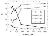
도 3a는 본 발명에 따라 합성된 Cd 및 황-풍부 중간영역을 갖는 양자점에 대한 반응시간에 따른 반응물질의 원자농도 그래프이다.
도 3b는 본 발명에 따라 합성된 Zn 및 셀레늄-풍부 중간영역을 갖는 양자점에 대한 반응시간에 따른 반응물질의 원자농도 그래프이다.
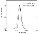
도 4는 본 발명에 따라 합성된 CdS-풍부 또는 ZnSe-풍부 중간영역을 갖는 녹색 양자점으로부터의 광발광 그래프이다.
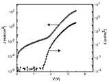
도 5는 본 발명에 따라 합성된 Cd 및 S-풍부, 또는 Zn 및 Se-풍부 중간층을 포함하는 녹색 발광 양자점을 갖는 QD-LED에 대한 전압 (V)에 따른 전류밀도 (J) 및 휘도 (L)를 나타내는 그래프이다.
도 6은 본 발명에 따라 합성된 Cd 및 S-풍부, 또는 Zn 및 Se-풍부 중간층을 포함하는 녹색 발광 양자점을 갖는 QD-LED에 대한 휘도 (L)에 따른 전류효율 (ηA) 및 외부 양자효율 (ηEQE)을 나타내는 그래프이다.
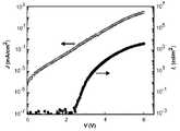
도 7은 본 발명에 따라 합성된 적색 발광 양자점을 갖는 QD-LED로부터의 전기발광 그래프이다.
도 8은 본 발명에 따라 합성된 적색 발광 양자점을 갖는 QD-LED에 대한 전압 (V)에 따른 전류밀도 (J) 및 휘도 (L)를 나타내는 그래프이다.
도 9는 본 발명에 따라 합성된 적색 발광 양자점을 갖는 QD-LED에 대한 휘도 (L)에 따른 전류효율 (ηA) 및 외부 양자효율 (ηEQE)을 나타내는 그래프이다.
도 10은 본 발명에 따라 합성된 진청색 (deep blue, λmax~450nm) 및 하늘색 (sky blue, λmax~470nm) 양자점으로부터의 광발광 그래프이다.
도 11은 본 발명에 따른 TFB 정공 수송층을 이용한 진청색 방출 양자점을 갖는 QD-LED에 대한 전압 (V)에 따른 전류밀도 (J) 및 휘도 (L)를 나타내는 그래프이다.
도 12는 본 발명에 따른 TFB 정공 수송층을 이용한 진청색 방출 양자점을 갖는 QD-LED에 대한 휘도 (L)에 따른 전류효율 (ηA) 및 외부 양자효율 (ηEQE)을 나타내는 그래프이다.1 is a schematic diagram of a QD-LED according to the prior art.
2 is a schematic diagram of the gradient composition of the quantum dot nanoparticles according to the present invention.
FIG. 3A is a graph of the atomic concentration of reactants with respect to reaction time for quantum dots having Cd and sulfur-rich intermediate regions synthesized according to the present invention. FIG.
FIG. 3B is a graph showing the atomic concentration of reactants with respect to reaction time for quantum dots having Zn and selenium-rich intermediate regions synthesized according to the present invention.
4 is a photoluminescence graph from a green quantum dot having a CdS-rich or ZnSe-rich middle region synthesized according to the present invention.
FIG. 5 is a graph showing current density J and luminance (L) of a QD-LED having green light emitting quantum dots including Cd and S-rich portions or Zn and Se- rich intermediate layers synthesized according to the present invention, ).
6 is a graph showing current efficiency (ηA ) according to luminance (L) for a QD-LED having Cd and S-rich portions or Zn and Se-rich intermediate layers synthesized according to the present invention and having green emission quantum dots, Efficiency < RTI ID = 0.0 > (EQE ). ≪ / RTI >
7 is a graph of electroluminescence from QD-LEDs having red light emitting quantum dots synthesized in accordance with the present invention.
8 is a graph showing a current density J and a luminance L according to a voltage V for a QD-LED having red light emitting quantum dots synthesized according to the present invention.
9 is a graph showing a current efficiency (ηA ) and an external quantum efficiency (ηEQE ) according to a luminance (L) for a QD-LED having red light emitting quantum dots synthesized according to the present invention.
10 is a photoluminescence graph from deep blue (λmax to 450 nm) and sky blue (λmax to 470 nm) quantum dots synthesized according to the present invention.
11 is a graph showing current density (J) and luminance (L) according to voltage (V) for a QD-LED having a blue color emitting quantum dot using a TFB hole transporting layer according to the present invention.
12 is a graph showing a current efficiency (ηA ) and an external quantum efficiency (ηEQE ) according to the luminance (L) for a QD-LED having a blue-emitting emission quantum dot using a TFB hole transporting layer according to the present invention.
본 발명에 따른 발광 다이오드의 적색, 녹색 또는 청색 발광층에 사용하기 위한 양자점은 CdxZn1-xSeyS1-y 조성을 가지는 중심, 여기서 0<X≤0.5, 및 0.5≤Y<1 및 0≤Y<0.5 중 하나이고; CdxZn1-xSeyS1-y 조성을 가지는 표면, 여기서 0<X≤0.5 및 0<Y≤0.5이고; 및 CdxZn1-xSeyS1-y의 조성을 가지는 상기 중심과 상기 표면 사이의 대략 중간 구조, 여기서 0<X≤0.5, 및 0.5≤Y<1 및 0≤Y<0.5 중 하나를 포함하는 구조를 가진다.Quantum dots for use in the red, green and blue light-emitting layer of the LED according to the present invention Cdx Zn1- center havingx Sey S1-y composition, where 0 <X≤0.5, and 0.5≤Y <1 and 0 Lt; Y <0.5; Cdx Zn1- surface havingx Sey S1-y composition, where 0 <X≤0.5 and 0 <Y≤0.5 gt; AndCd x Zn 1 - x Se y S1-y having a composition of approximately intermediate structure between the center and the surface, wherein 0 <X≤0.5, and 0.5≤Y <1 and 0≤Y <0.5 comprises one of .
도 2에 도시된 바와 같이, 각 양자점 (100)은 중심 (102) 및 표면 (104)을 포함한다. 중간영역 (106)은 중심 (102)에서 표면 (104)으로 연장된다. 중심 및 표면 근처 영역 및 중간영역 (106)은 서브-영역(sub-region)으로 형성될 수 있다. 상기 구조는 중심에서 표면으로의 양자점의 반경에 걸쳐 연속적으로 변하는 조성을 갖는다.As shown in FIG. 2, each of the
이상적인 구형의 양자점의 중심, 중간영역 및 표면은 도 2에 개략적으로 도시되어 있다.The center, middle region and surface of the ideal spherical quantum dot are schematically shown in Fig.
후술되는 바와 같이, 상기 구조는 카드늄과 아연 간의 상이한 반응성 및 셀레늄 전구체와 황 전구체 간의 상이한 반응성으로 인해 형성된다. 보다 반응성이 큰 카드늄 및 셀레늄 전구체는 먼저 Cd-풍부 및 Se-풍부 중심 (102)의 핵형성을 야기시킨 다음, 보다 반응성이 적은 Zn 및 Se 전구체는 표면 (104) 및 중간영역 (106)의 형성에 서서히 참여하여, 양자점 (100)의 라디칼 방향 (중간영역 (106)을 통과)을 따라 연속적인 화학적 조성 구배를 형성한다.As described below, the structure is formed due to the different reactivity between cadmium and zinc and the different reactivity between the selenium precursor and the sulfur precursor. The more reactive cadmium and selenium precursors first cause nucleation of the Cd-enriched and Se-
이러한 구배형 구조의 결과, 종래 기술의 영역 사이의 비연속적 경계면은 소멸된다. 본 발명의 화학적 조성 구배 구조는, 경계면 결함 및 불규칙한 나노입자 성장을 일으키고, 발명자가 낮은 양자효율의 주원인 중 하나로 생각하는, 중심, 표면 및 중간영역 사이의 상당한 격자 불일치를 제거시킨다.As a result of this gradient structure, the discontinuous interface between the regions of the prior art is extinguished. The chemical composition gradient structure of the present invention eliminates the significant lattice mismatch between the center, the surface and the intermediate regions, which causes interface defects and irregular nanoparticle growth and which the inventor considers to be one of the main sources of low quantum efficiency.
상기 양자점은 적색, 청색 및 녹색 LED 각각의 발광 다이오드에 적용되고 결합될 수 있는 구조를 가진다. 후술되는 바와 같이, 중심, 중간영역 및 표면 각각의 카드늄, 아연, 셀레늄, 및 황의 상대적인 함량 및 이들 간의 조성 구배를 제어하여 양자점을 합성하는데 있어서, 양자점에 의해 형성된 발광층의 출력 특성은 적색, 청색, 또는 녹색 LED를 위한 발광층을 형성하도록 설정될 수 있다. 각 양자점의 합성방법은 이하 색깔별로 설명될 것이다.The quantum dots have a structure that can be applied to and coupled to red, blue, and green LEDs, respectively. As described below, in synthesizing quantum dots by controlling the relative amounts of cadmium, zinc, selenium, and sulfur in the center, middle region, and surface, respectively, and the composition gradient therebetween, the output characteristics of the light emitting layer formed by the quantum dots are red, Or a light emitting layer for a green LED. The synthesis method of each quantum dot will be described below by color.
녹색green양자점Qdot
각 양자점은 원-포트 공정(one pot method)을 사용하여 합성된다. 원-포트 공정에 있어서, 구성성분 각각이 함께 혼합되고 라디칼 구조는 적어도 다음을 포함하는 다수의 변수를 제어하여 결정된다: (i) 전구체의 종류, (ii) 반응시간, (iii) 반응온도, 및 (iv) 반응환경. 녹색 LED를 위한 양자점 합성에 있어서, 양이온 혼합용액은 아연 반응물질, 카드늄 반응물질 및 용매로 형성된다. 일반적인 용매는 비배위 용매이나 배위 용매도 사용될 수 있다. 바람직한 실시예에 있어서, 카드늄 및 아연 각각은 올레산으로 형성되고, 비배위 용매는 1-옥타데센이다. 이렇게 혼합된 용액은 양이온 용액을 형성한다.Each quantum dot is synthesized using a one pot method. In a one-pot process, each of the components is mixed together and the radical structure is determined by controlling a number of variables including at least: (i) the type of precursor, (ii) the reaction time, (iii) And (iv) the reaction environment. In quantum dot synthesis for a green LED, a cationic mixed solution is formed of a zinc reactant, a cadmium reactant and a solvent. As a general solvent, a non-coordination solvent or a coordination solvent may be used. In a preferred embodiment, each of cadmium and zinc is formed of oleic acid and the non-coordinating solvent is 1-octadecene. This mixed solution forms a cationic solution.
양이온 용액은 셀레늄 전구체 및 황 전구체와 혼합된다. 바람직한 실시예에 있어서, 상기 셀레늄 전구체 및 황 전구체는 양이온 혼합용액과 동시에 혼합된다. 후술되는 바와 같이, 전구체의 종류는 달라질 수 있다. 본 발명의 목적을 위해서, 전구체의 종류는 황 또는 셀레늄 또는 기타 반응물질이 전구체를 형성하기 위해 혼합되는 물질을 의미한다. 녹색광 방출 양자점을 위한 바람직하나, 제한되지 않는 실시예에 있어서, 셀레늄 및 황은 상기 전구체 (각각 Se-TOP 및 S-TOP)를 형성하기 위하여 트리옥틸포스핀에 용해된다. 상기 셀레늄 전구체 및 황 전구체는 음이온 전구체로서 형성되고, 290 ~ 310℃ 온도, 비제한적 실시예로서 바람직하게는 약 300℃의 온도에서 양이온 혼합용액에 실질적으로 동시에 혼합되고, N2, He, Ne, Ar, Kr 또는 Xe와 같은 불활성 분위기, 이에 제한되는 것은 아니나 바람직하게는 아르곤 분위기하에서 1 내지 약 500분, 이에 제한되는 것은 아니나 바람직하게는 약 10분 동안 반응된다.The cation solution is mixed with the selenium precursor and the sulfur precursor. In a preferred embodiment, the selenium precursor and the sulfur precursor are mixed simultaneously with the cationic mixed solution. As will be described later, the kind of the precursor can be varied. For purposes of the present invention, the type of precursor refers to a material in which sulfur or selenium or other reactive material is mixed to form a precursor. In a preferred but non-limiting embodiment for green light emitting quantum dots, selenium and sulfur are dissolved in trioctylphosphine to form the precursors (Se-TOP and S-TOP, respectively). The selenium precursor and the sulfur precursor is formed as an anion precursor, 290 ~ 310 ℃ temperature, preferably as non-limiting examples are mixed at substantially the same time to the cation mixture solution at a temperature of about 300 ℃, N2, He, Ne, In an inert atmosphere such as Ar, Kr or Xe, for example, but not limited to, for 1 to about 500 minutes, preferably, about 10 minutes under an argon atmosphere.
상기 기술한 바와 같이, 모든 전구체가 양이온 혼합용액에 실질적으로 동시에 혼합되기 때문에 중심의 조성, 표면의 조성 및 중간영역의 두께 및 조성을 포함한 양자점 (100)의 구조 변수는 반응물질/전구체의 상대적인 함량 및 종류에 의해 동시에 제어될 수 있다.As all precursors are substantially simultaneously mixed with the cationic mixed solution as described above, the structural parameters of the
일반적으로, 아연 전구체의 상대적인 함량은 나머지 전구체의 함량을 초과한다. 아연 전구체의 함량은 표면의 범위(extent) 및 조성 구배에 큰 영향을 미친다. 카드늄 및 셀레늄 전구체의 상대적인 함량은 중심에서의 조성 및 조성 구배에 큰 영향을 미친다. 중심으로 접근할수록 중간영역의 구조는 모든 전구체 비율에 의해 영향을 받는다. 셀레늄에 비해 과량의 카드늄은 카드늄 황 풍부 중간영역을 생성하는 반면, 셀레늄이 카드늄의 함량보다 상대적으로 많이 혼합물에 사용된 경우, 아연 셀레늄-풍부 중간영역이 형성된다. 표면 조성은 주로 황 전구체의 함량에 의해 결정된다. 그러나, 구조 또는 변수는 하나의 전구체의 절대적인 함량에 의해 독립적으로 제어되지 않는다. 일반적 실시예에 있어서, 아연은 과량이고, Zn/Cd의 비는 대략 20이다. CdS 풍부한 중간영역에 대해서는 일반적인 Cd/Zn 비는 2.0이다. ZnSe-풍부 중간영역 조성에 대해서는 Se/Cd 비는 일반적으로 5이다.Generally, the relative content of the zinc precursor exceeds the content of the remaining precursor. The content of zinc precursor has a great influence on the extent and composition gradient of the surface. The relative content of cadmium and selenium precursors has a significant effect on the composition and composition gradient at the center. As we approach the center, the structure of the middle region is affected by all the precursor ratios. An excess of cadmium compared to selenium produces a cadmium-rich sulfur intermediate region, whereas when selenium is used in a relatively higher amount of cadmium, a zinc selenium-rich intermediate region is formed. The surface composition is mainly determined by the content of the sulfur precursor. However, the structure or variable is not independently controlled by the absolute content of one precursor. In a typical embodiment, zinc is excessive and the ratio of Zn / Cd is approximately 20. For CdS-rich intermediate regions, the typical Cd / Zn ratio is 2.0. The Se / Cd ratio is generally 5 for the ZnSe-rich intermediate zone composition.
상기 기재된 합성방법의 사용은 QD- LED용 효율적 녹색 양자점을 성장시킨다. 녹색 양자점의 방출 피크 파장은 505nm 내지 555nm 범위에서 조정될 수 있다. 동시에 양자효율은 80 퍼센트로 또는 그 이상으로 유지되고, 전기발광 피크의 반치전폭(full width half maximum, FWHM)은 40nm 미만이다. 상기 범위를 벗어난 방출 피크를 갖는 양자점도 얻을 수 있으나, 40% 내지 80%의 양자효율을 갖는다. 녹색 양자점의 화학조성이 CdS-풍부 중간영역 (106)에서 ZnSe-풍부 중간영역 (106)으로 변화할 때 전계발광소자 성능에 있어서 현저한 차이를 보인다; 그러나 두 종류의 녹색 양자점이 광발광 양자효율 및 광발광 스펙트럼과 같은 광학적 특성은 유사함을 보인다. 이는 고성능의 QD-LED를 제공에 있어서 양자점의 광학적 특성 및 전기적 특성의 중요성을 나타낸다.The use of the synthesis method described above grows efficient green quantum dots for QD-LEDs. The emission peak wavelength of the green quantum dot can be adjusted in the range of 505 nm to 555 nm. At the same time, the quantum efficiency is maintained at 80 percent or more, and the full width half maximum (FWHM) of the electroluminescent peak is less than 40 nm. Quantum dots having emission peaks out of the above range can also be obtained, but have a quantum efficiency of 40% to 80%. The green quantum dot shows a remarkable difference in the electroluminescent device performance when the chemical composition changes from the CdS-rich
도 3a, 3b에서 XPS (X-ray photoelectron spectroscopy)에 의해 측정된 QD의 표면 조성을 CdS-풍부 (도 3a) 또는 ZnSe-풍부 (도 3b) 중간영역을 갖는 QD의 반응시간의 함수로 나타내었다. 300 ℃ 미만에서 600초까지의 성장시간 동안 중간영역은 서너 초에서 200초 사이의 반응시간에 형성된다. CdS 풍부 중간영역에 대하여 도 3a에서 도시된 바와 같이, Se 조성은 <10 at.%로 낮다. 이는 제한된 셀레늄 공급이 중심을 형성하는데 대부분 사용된 반면, 아연 및 황 성분은 표면 (104)에서 우세하기 때문이다.The surface composition of QD measured by X-ray photoelectron spectroscopy (XPS) in FIGS. 3a and 3b is shown as a function of the reaction time of QD with CdS-rich (FIG. 3A) or ZnSe-rich (FIG. During the growth time from less than 300 DEG C to 600 seconds, the intermediate region is formed at a reaction time of between 3 and 200 seconds. As shown in FIG. 3A for the CdS rich intermediate region, the Se composition is as low as <10 at.%. This is because the limited selenium supply is mostly used to form the center while the zinc and sulfur components predominate on the
이와 반대로, 도 3b에서 도시된 바와 같이, ZnSe-풍부 중간영역을 갖는 녹색 양자점 (100)은 보다 높은 셀레늄 중심 농도 (약 20 at.% 초기 100초의 성장 동안)를 보이고, 카드늄이 중심 (102)의 핵형성 및 성장에 소비됨으로 인해 카드늄 조성을 서서히 초과함을 보인다. 이는 ZnS-풍부 표면을 갖는 ZnSe-풍부 중간영역 (106)을 형성시킨다. 두 가지 타입의 QD의 중간영역은 CdxZn1-xSeyS1-y의 조성을 가지고, 여기서, CdS-풍부 중간층에 대해서는 x는 더 크고 y는 더 작고, ZnSe-풍부 중간영역에 대해서는 x는 더 작고 y는 더 크다.3B, the
두 가지 타입의 양자점은 뚜렷하게 상이한 형태를 가진다. ZnS-풍부 중간영역 (106)을 갖는 양자점의 평균 크기는 약 10 nm로 더 크다. 이와 반대로, ZnSe-풍부 중간영역 (106)을 갖는 양자점은 더 작은 약 7 내지 8 nm의 입자크기를 갖는다. 황의 함량은 주로 두께를 결정하기 때문에, 더 작은 크기의 양자점은 보다 얇은 ZnS 표면으로부터 결과한다. 이는 전기발광 동안 양자점 발광층에서 전하 주입 및 수송의 균형을 위해 중요하다. 적색 QD에 있어서 S:Zn 비는 약 1:20이고; 녹색 QD에 있어서 S:Zn 비는 약 1:2이고; 및 청색 QD에 있어서 크기의 비는 1:2 보다 크다.The two types of quantum dots have distinctly different forms. The average size of the quantum dots having the ZnS-rich
도 4에 도시된 바와 같이, CdS 또는 ZnSe-풍부 중간영역을 갖는 QD는 유사한 광발광 스펙트럼을 가지고, CdS-풍부 양자점은 약 530nm에서 ZnSe-풍부 양자점은 약 533nm에서, 즉, 녹색광 범위에서, 방출피크를 가진다. 또한, CdS-풍부 양자점은 37nm FWHM을 가지고, 이는 ZnSe-풍부 양자점이 25nm FWHM인 것과 비교하여 크다. 반면에 광발광 양자 수득율(quantum yield)는 유사하였다 (각각 65% 및 70%).As shown in Fig. 4, QD with a CdS or ZnSe-rich intermediate region has a similar photoluminescence spectrum, CdS-rich quantum dots at about 530 nm, ZnSe-rich quantum dots at about 533 nm, It has a peak. In addition, the CdS-rich QdS has a 37 nm FWHM, which is larger than that of the ZnSe-rich QdS at 25 nm FWHM. On the other hand, the photoluminescence quantum yields were similar (65% and 70%, respectively).
도 4에서 알 수 있듯이, CdS-풍부 및 ZnSe-풍부 중간영역 양자점의 광발광 스펙트럼의 차이점은 아주 작다. 그러나, LED의 발광층으로 사용될 경우 전기발광 특성은 매우 다르다. 도 5에서 도시된 바와 같이, 방출층의 두 가지 유형의 양자점을 이용한 QD-LED의 도 5의 전류밀도-휘도-전압 및 도 6의 효율특성은 현저히 다르다. CdS-풍부 중간영역을 갖는 양자점을 갖는 양자점 LED와 비교하여, ZnSe-풍부 중간영역 (106)을 갖는 양자점은 3 볼트 미만의 전압에서는 낮은 누설전류(leakage current)를 나타내고, 3 볼트 이상의 전압에서는 높은 순방향 주입 전류(forward injection current)를 나타낸다. 즉, 보다 낮은 누설전류와 함께 더욱 우수한 다이오드 특성을 ZnSe-풍부 중간영역을 이용하는 QD로부터 얻었다. 녹색 발광 다이오드를 위해 사용될 경우, CdS-풍부 중간영역을 갖는 양자점으로 제조된 발광층과 비교하여 약 2 볼트의 턴-온 전압(turn-on voltage)에서 ZnSe-풍부 소자는 현저하게 낮은 구동전압을 가진다.As can be seen from Fig. 4, the difference in the photoluminescence spectra of the CdS-rich and ZnSe-rich middle region quantum dots is very small. However, when used as a light emitting layer of an LED, the electroluminescent characteristics are very different. As shown in FIG. 5, the current density-luminance-voltage of FIG. 5 of the QD-LED using two types of quantum dots of the emission layer and the efficiency characteristic of FIG. 6 are significantly different. In comparison with a quantum dot LED having a quantum dot having a CdS-rich intermediate region, a quantum dot having a ZnSe-rich
녹색 발광 다이오드에 있어서, ZnSe 양자점 소자가 1,000 cd/m2의 휘도를 생성하는데 구동전압이 약 3.3 볼트일 때 보다 우수한 효율성이 측정된다. 이와 반대로, CdS-풍부 소자는 1,000 cd/m2의 휘도를 얻기 위하여 약 4.6 볼트의 구동전압이 요구된다. 이는, 도 6에서 도시된 바와 같이, ZnSe-풍부 양자점 소자가 63 cd/A의 피크 전류효율 및 14.4 퍼센트의 외부 양자효율로 전류효율 및 외부 양자효율의 상당한 향상을 나타낸다. 33 cd/A의 피크 전류효율 및 단지 7.9 퍼센트의 외부 양자효율을 갖는 CdS-풍부 소자와 비교하여 거의 2배 증가됨을 보여준다. ZnSe-풍부 양자점은 약 100 내지 10,000 cd/m2의 발광범위에 걸쳐 넓고, 고효율을 갖는 QD-LED를 제공한다. 그 결과, ZnSe-풍부 중간영역을 갖는 양자점의 QD-LED는 디스플레이에 사용되는 종래 기술의 QD-LED 보다 적합하다.For a green light emitting diode, a ZnSe quantum dot device produces a luminance of 1,000 cd / m2 , and a better efficiency is measured when the driving voltage is about 3.3 volts. Conversely, a CdS-rich device requires a driving voltage of about 4.6 volts to achieve a luminance of 1,000 cd / m <2 & gt ;. This indicates that the ZnSe-rich quantum dot device exhibits a significant improvement in current efficiency and external quantum efficiency with a peak current efficiency of 63 cd / A and an external quantum efficiency of 14.4 percent, as shown in Fig. A peak current efficiency of 33 cd / A and a CdS-rich device with an external quantum efficiency of only 7.9 percent. ZnSe-rich quantum dots provide a QD-LED with a wide, high efficiency over a luminescent range of about 100 to 10,000 cd / m <2 >. As a result, QD-LEDs of quantum dots having a ZnSe-rich intermediate region are more suitable than those of the prior art QD-LEDs used in displays.
하기 표 1은 ZnSe-풍부 중간영역을 갖는 양자점과 CdS-풍부 중간영역을 갖는 양자점의 성능을 비교 및 요약한다.Table 1 below compares and summarizes the performance of quantum dots having a ZnSe-rich intermediate region and quantum dots having a CdS-rich intermediate region.
ZnSe-풍부 소자에 있어서, 감소된 구동전압은 60 Im/W의 전력효율의 상당한 증가를 초래한다. 이러한 결과는 아마도 전하 주입/수송 특성으로 인해 ZnSe-풍부 중간영역 (106)를 갖는 녹색 양자점이 CdS-풍부 중간영역을 갖는 녹색 양자점 보다 우수한 성능을 보임을 증명한다. 이는 ZnSe 및 CdS의 상이한 전도성 및 원자가 밴드 에너지 레벨에 의해 적어도 부분적으로 설명된다. CdS의 원자가 밴드의 상부는 약 6.3eV이므로, 약 5.9 eV의 원자가 밴드를 갖는 ZnSe와 비교하여, 방출성의 CdS 중심 영역으로의 정공 주입은 보다 어렵다. 또한, ZnSe-풍부 중간영역 (106)의 성장은 보다 얇은 ZnS 표면 (104)을 초래하여 양자점 방출층 내에서 전하 전이를 용이하게 할 수 있다. 이는 상기 도면 및 표에서 도시된 바와 같이 증가된 효율성을 나타낸다.For ZnSe-rich devices, the reduced drive voltage results in a significant increase in power efficiency of 60 Im / W. These results demonstrate that the green quantum dot with the ZnSe-rich
적색 LEDRed LED
상기 기재된 바와 같이, 적색 양자점 LED의 발광층으로 사용하기 위하여 향상된 결과를 제공하기 위하여 동일한 구성의 반응물질을 사용하여 조성 및 구배 구조는 변경될 수 있다. 원-포트 합성방법은 양자점의 방출 파장을 녹색에서 적색으로의 적색 이동에 사용될 수 있다. 일반적으로, 녹색 양자점을 위한 상대적인 함량을 비교할 때, 적색 방출을 위해 셀레늄 전구체의 함량은 황 전구체에 비하여 증가된다. 이는 셀레늄 전구체의 절대량을 증가시키고 황 전구체의 함량을 감소시킴에 의해 수행될 수 있다.As described above, the composition and the gradation structure can be changed using reactants of the same composition to provide improved results for use as the light emitting layer of the red quantum dot LED. The one-port synthesis method can be used to red shift the emission wavelength of the quantum dot from green to red. Generally, when comparing the relative content for the green quantum dot, the content of the selenium precursor for red emission is increased relative to the sulfur precursor. This can be done by increasing the absolute amount of the selenium precursor and decreasing the content of the sulfur precursor.
녹색 양자점 및 적색 양자점을 합성하기 위한 원-포트 공정 간의 주요 다른점은 음이온 전구체가 양이온 용액에 순차적으로(step-wise) 주입되는 것이다. 이러한 방법으로 셀레늄 전구체의 제1 주입은 중심의 특성 및 중간영역 조성 및 두께를 주로 제어한다. 황 전구체의 제2 주입은 표면의 특성을 주로 제어하여 제어 가능성 및 제어능을 갖는 적색 양자점을 생성한다. 투-포트 합성방법과는 달리, 원-포트 합성방법은 중단 없이 중심 및 표면의 성장 완료를 허용하고 추가의 정제단계를 요구하지 않는다.The main difference between the one-port process for synthesizing the green quantum dot and the red quantum dot is that the anion precursor is injected step-wise into the cation solution. In this way, the first injection of the selenium precursor primarily controls the properties of the center and the middle zone composition and thickness. The second implantation of the sulfur precursor produces red quantum dots with controllability and controllability primarily by controlling the surface properties. Unlike the two-port synthesis method, the one-port synthesis method allows the completion of center and surface growth without interruption and does not require an additional purification step.
특히, Se 전구체는 제1 단계로 상술한 상기 혼합 양이온 용액에 주입되어 중심을 형성한다. ZnSe-풍부 중간영역도 이 단계에서 생성될 것이다. 그런 다음 황 전구체 및 소량 (최초 Se 전구체 함량의 약 10%)의 셀레늄 전구체가 제2 단계로 상기 양이온 혼합용액에 넣어진다. 셀레늄의 제2 주입은 중간영역을 형성하는 다른 영역간의 격자 불일치를 감소시키기 위하여 연속적 조성 구배를 생성한다. ZnS 표면의 두께는 제2 단계에서 양이온 혼합용액에 주입된 황 전구체의 함량을 변경함으로써 조정될 수 있다.In particular, the Se precursor is injected into the mixed cation solution described above as the first step to form a center. A ZnSe-rich intermediate region will also be generated at this stage. The sulfur precursor and a small amount (about 10% of the initial Se precursor content) of the selenium precursor are then introduced into the cationic mixed solution in a second step. The second implantation of selenium produces a continuous composition gradient to reduce lattice mismatch between other regions forming the intermediate region. The thickness of the ZnS surface can be adjusted by changing the content of the sulfur precursor injected into the cationic mixed solution in the second step.
상기 방법에서, 음이온 전구체의 종류는 각각 용매, 예를 들어, 트리옥틸포스핀에 용해된 셀레늄 및 황이다. Se-TOP 전구체를 형성하는 일반적인 조건은 불활성 분위기에서 2시간 동안 110℃이다.In this method, the types of anion precursors are respectively selenium and sulfur dissolved in a solvent, for example, trioctylphosphine. Typical conditions for forming Se-TOP precursors are 110 < 0 > C for 2 hours in an inert atmosphere.
적색-방출 QD-LED의 모든 영역의 조성은 CdxZn1-xSeyS1-y 이고, 상기 중심은 CdSe-풍부이고, 상기 중간영역은 ZnSe-풍부이고, 및 상술한 바와 같이 상기 합성된 적색 양자점의 표면은 ZnS-풍부이다. 양자점의 중심, 중간영역 및 표면 간의 조성은 연속적으로 변하고 얕은 조성 구배로 제공된다. 양자점의 평균 입자크기는 8nm이다. 정제 및 옥탄티올과의 리간드 교환 후, 상기 구조를 갖는 적색 양자점의 광발광 양자 수득율은 약 65 퍼센트이다.The composition of all regions of the red-emitting QD-LED is Cdx Zn1-x Sey S1-y , the center is CdSe-rich, the middle region is ZnSe-rich, and the synthesis The surface of the red quantum dots is ZnS-rich. The composition between the center, the middle region and the surface of the quantum dot is continuously varied and provided with a shallow composition gradient. The average particle size of the quantum dot is 8 nm. After purification and ligand exchange with octanethiol, the photoluminescence quantum yield of the red quantum dot having the above structure is about 65 percent.
도 7 내지 9에서 상기 기술한 구배로 구성된 양자점을 포함하는 적색-방출 QD-LED의 특성을 도시된다. 도 7에서 도시된 바와 같이, 적색 QD-LED는 약 25nm의 FWHM 및 약 625nm에서 방출 피크를 갖는 좁은 방출 스펙트럼을 가진다. 도 8에서 도시된 바와 같이, QD-LED는 또한 동일한 구동전압으로 보다 높은 전류주입 및 휘도를 나타낸다. 휘도는 약 2.7 볼트의 구동전압으로 1000 cd/m2에 이른다. 또한, 약 1.5 볼트의 문턱전압 이하 턴-온 전압(subthreshold turn-on voltage)이 관찰된다. 이는 정공 수송층/양자점층 계면에서 계면 오제 재결합(interfacial Auger recombination)을 일으켜 계면 장벽을 통과할 수 있는 핫 정공(hot hole)을 제공하는 것으로 여겨진다. 이는 방사 재결합을 야기시킨다. 그 결과, 도 8에서 도시된 바와 같이, 적색 양자점은 약 12 퍼센트의 높은 외부 양자효율 및 약 15 cd/A의 전류효율을 나타낸다.The characteristics of the red-emitting QD-LEDs comprising quantum dots composed of the grades described above in Figs. 7-9 are shown. As shown in FIG. 7, the red QD-LED has a narrow emission spectrum with an FWHM of about 25 nm and an emission peak at about 625 nm. As shown in FIG. 8, the QD-LED also exhibits higher current injection and brightness with the same drive voltage. The luminance reaches 1000 cd / m2 at a drive voltage of about 2.7 volts. In addition, a subthreshold turn-on voltage of about 1.5 volts is observed. It is believed that this provides a hot hole through the interfacial barrier by causing interfacial Auger recombination at the hole transport layer / quantum dot layer interface. This causes radiation recombination. As a result, as shown in FIG. 8, the red quantum dot exhibits a high external quantum efficiency of about 12 percent and a current efficiency of about 15 cd / A.
청색blueQDQD-LED-LED
상기 청색-방출 QD-LED의 모든 영역의 조성은 CdxZn1-xSeyS1-y이고, 여기서 y는 중심에서 0에 근접하여 CdS-풍부 중심을 만들고, 중간영역은 CdxZn1-xS-풍부이고, 및 상술한 바와 같이 합성된 청색 양자점의 표면은 ZnS-풍부이다. 조성은 양자점의 중심, 중간영역과 표면 사이에서 연속적으로 변하고 얕은 조성 구배로 제공된다. 상기 조성 구배는 QD-LED로부터 두 가지의 다른 청색 (하늘색 또는 진청색)을 생성하기 위하여 변형될 수 있다. 하늘색을 갖는 구조 (λmax~470 nm)는 중심에 보다 많은 함량의 CdSe를 가질 수 있다. 본 실시예에 있어서, 셀레늄 전구체의 함량은 황 전구체에 비하여 매우 소량이다 (일반적으로 400 중량부(parts)의 S에 대하여 1 중량부(part)의 Se). 진청색 방출 (λmax~450 nm)을 갖는 양자점은 Cd1-xZnxS 중심을 갖는다. 그 결과 양자점은 Cd1-xZnxS -풍부 중간영역 및 두꺼운 ZnS 표면을 갖는 구조를 형성한다. QD는 진청색을 방출한다.The blue-emitting composition of all areas of the QD-LED is Znx Cd1-x and SeyS1-y, where y is close to zero in the center to create a rich CdS- center, an intermediate area Cdx Zn1-x S-rich, and the surface of the blue quantum dot synthesized as described above is ZnS-rich. The composition changes continuously between the center, middle region of the quantum dot and the surface and is provided with a shallow composition gradient. The composition gradient can be modified to produce two different blue (blue or dark blue) colors from the QD-LED. The structure with light blue (λmax ~ 470 nm) can have a higher content of CdSe at the center. In this example, the selenium precursor content is very small compared to the sulfur precursor (typically, one part by weight of S for 400 parts by weight of S). Quantum dots with a dark blue emission (λmax to 450 nm) have a Cd1-x Znx S center. As a result, the quantum dots form a structure with a Cd1-x Znx S - rich intermediate region and a thick ZnS surface. QD emits dark blue.
일반적으로 원-포트, 투-포트 주입 합성방법이 사용된다. Cd1-xZnxS 중심 영역은 보다 반응성이 큰 황 전구체를 양이온 용액에 넣음으로써 형성된다. 바람직하나 제한되지 않는 실시예에 있어서, 이러한 제1 주입은 1-옥타데센에 2시간에 걸쳐 110℃에서 용해된 황의 황 전구체를 사용한다. 상기 제1 주입은 약 310℃의 온도에서 수행되고 약 8분 동안 반응된다.Generally, a one-port, two-port injection synthesis method is used. The Cd1-x Znx S central region is formed by introducing a more reactive sulfur precursor into the cationic solution. In a preferred but not limiting embodiment, this first injection uses a sulfur precursor of sulfur dissolved in 1-octadecene at 110 DEG C over 2 hours. The first injection is performed at a temperature of about 310 < 0 > C and is reacted for about 8 minutes.
보다 반응성이 적은 황 전구체의 제2 주입은 ZnS 표면 성장을 촉진시키기 위하여 첨가된다. 바람직하나 제한되지 않는 일 실시예에 있어서, S 전구체는 S-TOP 유형이다. 또한 제2 전구체는 310℃에서 30 내지 40분 동안 반응되어 양자점의 열처리를 수행한다. 이러한 긴 열처리 시간은 양자점 내의 결함을 감소시키고 양자 수득율을 높인다.A second injection of less reactive sulfur precursor is added to promote ZnS surface growth. In one preferred but not limiting embodiment, the S precursor is of the S-TOP type. And the second precursor is reacted at 310 DEG C for 30 to 40 minutes to perform the heat treatment of the quantum dot. This long annealing time reduces the defects in the quantum dots and increases the quantum yield.
상기 중심영역을 기반으로 한 방출 파장은 진청색에서 하늘색으로, 즉 λmax 430nm에서 490nm으로, 연속적으로 변할 것이다. 80 퍼센트의 높은 광발광 양자효율을 필요로 하나, 효율적인 QD-LED에서 λmax~450nm에서 진청색 방출하는 QD에 대해서는 충분한 조건은 아니다. Cd1-xZnxS 코어영역을 갖는 양자점은 바람직한 진청색 에미터(emitter)이다.The emission wavelength based on the central region will change continuously from dark blue to sky blue, i.e., from λmax 430 nm to 490 nm. It is not a sufficient condition for a QD that requires a high photon emission quantum efficiency of 80 percent, but emits a deep blue color at λmax to 450 nm in an efficient QD-LED. The quantum dot having a Cd1-x Znx S core region is a preferred dark blue emitter.
하늘색 양자점으로 사용될 경우, CdS-풍부 중간영역 및 상대적으로 두꺼운 ZnS 표면을 갖는 양자점은 약 12nm의 보다 큰 입자크기 및 불규칙한 형상을 생성할 것이다. 이와 반대로, Cd1-xZnxS/ZnS 양자점은 약 8nm의 입자크기를 갖는 보다 규칙적인 형상을 가짐으로 인해 우수한 입자의 자기조립(self assembly)을 하게한다. 도 10에서 도시된 바와 같이, 진청색 및 하늘색 양자점의 광발광 강도(PL intensity)는 각각 약 455 및 477nm에서 최대값 및 각각 20 및 24nm의 FWHM를 보였다.Quantum dots with a CdS-rich intermediate region and a relatively thick ZnS surface when used as sky blue quantum dots will produce larger particle sizes and irregular shapes of about 12 nm. Conversely, the Cd1-x Znx S / ZnS quantum dots have more regular shapes with a particle size of about 8 nm, resulting in self assembly of good particles. As shown in FIG. 10, the photoluminescence intensities (PL intensities) of the dark blue and sky blue quantum dots showed maximum values at about 455 and 477 nm, respectively, and FWHM of 20 and 24 nm, respectively.
청색 양자점에 있어서, 셀레늄의 농도는 1 % 미만으로 예측되어 매우 낮다. 그 결과, 중심은 Cd1-xZnxS이고, 여기서 x는 1에 근접하고 중간영역은 Cd1-xZnxS이고, 여기서 x는 0.5에 근접하고, 표면은 Cd1-xZnxS이고 여기서 x는 0에 근접하다. 조성의 변화는 연속적이고 얕은 조성 구배로 제공된다. 중심 및 중간영역의 조성을 변화시켜 방출파장이 디스플레이 응용을 위해 보다 적합한 진청색으로 이동시킬 수 있다.For blue quantum dots, the concentration of selenium is predicted to be less than 1% and is very low. As a result, the center is Cd1-x Znx S, where x is close to 1 and the middle region is Cd1-x Znx S, where x is close to 0.5 and the surface is Cd1-x Znx S Where x is close to zero. Changes in composition are provided in a continuous, shallow composition gradient. The composition of the center and middle regions can be varied to shift the emission wavelength to a more suitable dark blue color for display applications.
TFB 정공 수송층을 이용한 진청색 방출 양자점을 갖는 QD-LED의 전압 (V)에 따른 전류밀도 (J) 및 휘도 (L)는 도 11에 도시되었다. TFB 정공 수송층을 이용한 진청색 방출 양자점을 갖는 QD-LED의 휘도 (L)에 따른 전류효율 (ηA) 및 외부 양자효율(ηEQE)은 도 12에 도시되었다.The current density (J) and the luminance (L) according to the voltage (V) of the QD-LED having the blue-emitting emission quantum dot using the TFB hole transporting layer are shown in FIG. The current efficiency (ηA ) and the external quantum efficiency (ηEQE ) according to the luminance (L) of the QD-LED having the blue-emitting emission quantum dot using the TFB hole transport layer are shown in FIG.
최첨단에 익숙한 사람은 TFB 이외의 물질이, 예를 들어 TFB 보다는 폴리비닐 카바졸 (PVK)이 정공을 수송하고, 방출층으로 이들을 주입하기에 사용될 수 있음을 알 것이다.Those skilled in the art will appreciate that materials other than TFB can be used to transport holes, for example polyvinyl carbazole (PVK) rather than TFB, and to inject them into the emissive layer.
하기 표 2에서 보여주는 바와 같이, 향상된 양자점 LED가 원-포트 방법에 의해 얻어지고, 중심, 중간영역 및 표면의 조성의 최적화는, 높은 효율 및 높은 밝기를 갖는 소자의 바람직한 파장을 방출하는 양자점을 생성하기 위하여 조정될 수 있다. 조성의 연속적인 변화를 이용하여, 조성의 불연속성으로 인한 종래 기술의 단점이 해소될 수 있다.As shown in the following Table 2, an improved quantum dot LED is obtained by the one-port method, and the optimization of the composition of the center, middle region and surface generates a quantum dot that emits the desired wavelength of the device with high efficiency and high brightness Can be adjusted. Using continuous changes in composition, the disadvantages of the prior art due to composition discontinuities can be overcome.
본 발명은 바람직한 실시예를 통해 설명되고 있지만, 해당 기술분야에서 통상의 지식을 가진 자라면 청구범위에 포함된 본 발명의 범위로부터 벗어나지 않는 한도에서 형상 및 디테일에 있어서 다양한 의견, 치환 및 변화가 만들어질 수 있다는 것을 이해할 수 있을 것이다. 따라서, 본 발명의 보호범위는 청구된 특허청구범위에 기재된 바에 의해 해석되어야 한다. 하기 청구범위는 본 발명에 개시된 모든 일반적 및 특정적 특징 및 본 발명의 보호범위를 포함하는 것으로 이해할 수 있을 것이다.While the present invention has been described by way of preferred embodiments, those skilled in the art will recognize that various changes, substitutions and changes in form and detail may be made therein without departing from the scope of the invention encompassed by the appended claims. You can understand that it can be. Accordingly, the protection scope of the present invention should be construed as described in the appended claims. It is to be understood that the following claims are inclusive of all general and specific features disclosed herein and the protection scope of the present invention.
Claims (76)
Translated fromKorean제어된 농도의 아연 반응물질, 카드늄 반응물질 및 용매를 포함하는 양이온 혼합용액을 제조하는 단계;
제어된 농도의 황 반응물질 및 제어된 농도의 셀레늄 반응물질을 포함하는 음이온 전구체를 상기 양이온 혼합용액에 용해시키는 단계;
반응속도를 제어하는 다음의 3개의 변수 중 적어도 하나를 변화시킴으로써, 양이온 혼합용액 내의 상기 셀레늄 반응물질 및 상기 황 반응물질 중 적어도 하나의 반응속도 및 정도를 제어하는 단계: (i) 반응시간, (ii) 반응온도 및 (iii) 반응물질의 종류; 및
불활성 환경에서 양이온 반응물질에 대한 음이온 반응물질의 상대적인 함량을 제어하는 단계
를 포함하는 양자점 나노입자 합성방법.
A method of synthesizing quantum dot nanoparticles that, when bound to a quantum dot light emitting diode emitting layer, emits light under electrical stimulation, said quantum dot having a composition that continuously varies across the nanoparticle radius from the center of the particle to the surface,
Preparing a cationic mixed solution comprising a controlled concentration of a zinc reactant, a cadmium reactant, and a solvent;
Dissolving an anionic precursor comprising a controlled concentration of sulfur reactant and a controlled concentration of selenium reactant in the cationic mixed solution;
Controlling the reaction rate and degree of at least one of the selenium reactant and the sulfur reactant in the cationic mixed solution by varying at least one of the following three variables controlling the reaction rate: (i) reaction time, ii) the reaction temperature and (iii) the type of reactant; And
Controlling the relative content of the anion reactive material to the cationic reactive material in an inert environment
Lt; RTI ID = 0.0 > nanoparticle < / RTI >
The method of claim 1, wherein the sulfur reactant and the selenium reactant are simultaneously dissolved in a cationic mixed solution.
The method of claim 1, wherein the selenium concentration in the selenium reactant is between 0 and 100%.
The method of claim 1, wherein the concentration of sulfur in the sulfur reactant material is between 0 and 100%.
The method of claim 1, wherein the zinc is present in an amount greater than the content of at least one of the selenium precursor and the sulfur precursor.
The method of claim 1, wherein the solvent is 1-octadecene.
2. The method of claim 1, wherein the selenium precursor and the sulfur precursor are mixed into a cationic mixed solution at a temperature of about 300 < 0 > C.
3. The method of claim 1, wherein the selenium precursor and the sulfur precursor are mixed into the cationic mixed solution for about 10 minutes.
The method of claim 1, wherein the inert environment is an argon atmosphere.
The method of claim 1, wherein the selenium precursor is formed by dissolving selenium in trioctylphosphine.
The method of claim 1, wherein the sulfur precursor is formed by dissolving sulfur in trioctylphosphine.
The method of claim 1, wherein the quantum dot nanoparticles have a region extending from the center to the surface and controlling the thickness of the region by providing zinc in an excess amount relative to the content of the selenium precursor and the content of the sulfur precursor Further comprising:
2. The method of claim 1, wherein the quantum dot nanoparticles have a region extending from the center to the surface, and further comprising providing selenium in excess of cadmium to control the size of the region.
The method of claim 1, wherein the particle size of the quantum dot is about 7-8 nanometers.
The method of claim 1, wherein the quantum dots emit green light.
The method of claim 1, wherein the cationic mixed solution comprises oleic acid.
상기 셀레늄 전구체 및 상기 황 전구체를 약 310 ℃의 온도에서 용해시키는 단계; 및
상기 셀레늄 전구체 및 상기 황 전구체를 약 10분 동안 상기 양이온 혼합용액에 혼합하는 단계를 더 포함하고,
여기서 상기 불활성 환경은 아르곤 분위기인 방법.
The process of claim 1 wherein the solvent is 1-octadecene,
Dissolving the selenium precursor and the sulfur precursor at a temperature of about 310 < 0 >C; And
Further comprising mixing the selenium precursor and the sulfur precursor into the cationic mixed solution for about 10 minutes,
Wherein said inert environment is an argon atmosphere.
The method of claim 1, wherein the relative content of selenium is greater than the relative content of cadmium.
제1의 상기 셀레늄 전구체를 혼합 베이스 용액에 주입하는 단계;
그런 다음 황 전구체를 상기 양이온 혼합용액에 주입하는 단계; 및
상기 제1의 셀레늄 전구체보다 적은 함량으로 제2의 셀레늄 전구체를 양이온 혼합용액에 상기 황 전구체의 주입과 실질적으로 동시에 주입하는 단계
를 더 포함하는 방법.
The method according to claim 1,
Injecting a first selenium precursor into a mixed base solution;
Then injecting the sulfur precursor into the cationic mixed solution; And
Injecting a second selenium precursor with a lesser content than the first selenium precursor substantially simultaneously with the injection of the sulfur precursor into the cationic mixed solution
≪ / RTI >
상기 셀레늄 전구체의 함량에 비해 과량의 함량으로 아연을 제공하여 영역의 두께를 제어하는 단계를 더 포함하는 방법.
The method of claim 19, wherein the quantum dot nanoparticles have a region extending from the center to the surface,
Further comprising providing zinc in an excess amount relative to the content of the selenium precursor to control the thickness of the region.
황 전구체의 함량에 비해 과량의 함량으로 아연을 제공하여 상기 중간영역의 두께를 제어하는 단계를 더 포함하는 방법.
20. The method of claim 19, wherein the quantum dot nanoparticles have an intermediate region extending from a center to a surface,
Further comprising providing zinc in an excess amount relative to the content of the sulfur precursor to control the thickness of the intermediate region.
카드늄의 함량을 초과하는 과량의 함량의 셀레늄을 제공하여 영역 크기를 제어하는 단계를 더 포함하는 방법.
20. The method of claim 19, wherein the quantum dot nanoparticles have an intermediate region extending from a center to a surface,
Further comprising providing an excess amount of selenium in excess of the content of cadmium to control the area size.
The method of claim 1, wherein the particle size of the quantum dot is about 8 nanometers.
상기 황 전구체의 함량 및 종류, 반응시간 및 반응온도를 제어하여 상기 영역의 두께를 제어하는 단계를 더 포함하는 방법.
The method of claim 19, wherein the quantum dot nanoparticles have a region extending from the center to the surface,
Controlling the content and type of the sulfur precursor, the reaction time, and the reaction temperature to control the thickness of the region.
The method of claim 1, wherein the center and the surface are formed of a certain amount of selenium, cadmium, zinc, and sulfur, and wherein the intermediate region is formed of a continuous concentration gradient of one or more of selenium, cadmium, zinc, .
26. The method of claim 25 wherein the center is a Cdx Zn1- has a compositionx Sey S1-y, where 0 <X≤0.5, and 0.5≤Y <1 and 0≤Y <is one of 0.5, and the surface Cdx Zn1- withx Sey S1-y composition, where 0 <X≤0.5 and 0 <Y≤0.5 gt; And a substantially intermediate composition between said center and said surface is Cdx Zn1-x Sey S1 -y , wherein 0 <X ≦ 0.5, and 0.5 ≦ Y ≦ 1 and 0 ≦ Y <0.5.
제1 황 전구체를 양이온 혼합용액에 용해시키는 단계, 여기서 상기 제1 황 전구체는 황을 1-옥타데센에 용해시켜 형성됨;
제2 황 전구체를 상기 양이온 혼합용액에 넣는 단계, 여기서 상기 제2 황 전구체는 황을 트리옥틸포스핀에 용해시켜 형성되는 단계를 더 포함하고;
상기 제1 황 전구체는 상기 제2 황 전구체보다 상기 혼합 용액과 더 반응성이 큰 방법.
The method according to claim 1,
Dissolving a first sulfur precursor in a cationic mixed solution, wherein the first sulfur precursor is formed by dissolving sulfur in 1-octadecene;
Introducing a second sulfur precursor into the cationic mixed solution, wherein the second sulfur precursor is formed by dissolving sulfur in trioctylphosphine;
Wherein the first sulfur precursor is more reactive with the mixed solution than the second sulfur precursor.
28. The method of claim 27, wherein the solvent is a coordination solvent and the coordination solvent is 1-octadecene.
28. The method of claim 27, further comprising maintaining the cationic mixed solution at a temperature of about 310 < 0 > C while the first and second sulfur precursors are reacting with the mixed base solution.
28. The method of claim 27, further comprising reacting the first sulfur precursor with the mixed base solution for about 8 minutes.
28. The method of claim 27, further comprising reacting the second sulfur precursor with the base solution for about 30 to 40 minutes.
The method of claim 1, wherein the quantum dot particle size is about 12 nanometers.
The method of claim 1, wherein blue light is emitted by the quantum dot under electrical stimulation.
28. The method of claim 27, wherein the cationic mixed solution comprises oleic acid.
The method of claim 1, wherein the red light is emitted by the quantum dot under electrical stimulation.
제2 조성의 표면을 포함하고, 여기서 제2 조성은 제1 조성과 다르고, 및
상기 중심과 표면 사이에서 연장되는 중간영역은 상기 중심과 표면 사이에서 연속 조성 구배를 갖는
전기 자극하에서 빛을 방출하기 위한 양자점.
The center of the first composition; And
Wherein the second composition is different from the first composition, and < RTI ID = 0.0 >
Wherein the intermediate region extending between the center and the surface has a continuous composition gradient between the center and the surface
Quantum dots to emit light under electrical stimulation.
37. The quantum dot of claim 36, wherein the content of CdSe in the center is larger than the content of ZnS in the center, and the content of CdSe in the center is larger than the content of ZnSe in the center.
37. The quantum dot according to claim 36, wherein the content of ZnS on the surface is larger than the content of CdSe on the surface.
37. The method of claim 36 wherein the center is a Cdx Zn1-x Sey S, and has a composition of1-y, where 0 <X≤0.5, and one of the 0.5≤Y <1 and 0≤Y <0.5, the surface the Cdx Zn1- has a compositionx Sey S1-y, where 0 <X≤0.5 and 0 <Y≤0.5 gt; And a substantially intermediate composition between the center and the surface is Cdx Zn1-x Sey S1 -y , where 0 <X ≦ 0.5, and 0.5 ≦ Y <1 and 0 ≦ Y <0.5.
37. The quantum dot of claim 36, having an internal quantum efficiency of 40 to 80 percent.
37. The quantum dot of claim 36, wherein at least one of the center, the surface and the middle region has a content of selenium greater than the content of cadmium.
37. The quantum dot of claim 36, wherein the relative content of the zinc precursor is greater than the relative content of selenium.
37. The quantum dot of claim 36, wherein the quantum dot has a particle size of about 7 nanometers to 8 nanometers.
37. The quantum dot of claim 36, having an emission peak at a wavelength from about 510 nm to about 540 nm.
37. The quantum dot of claim 36, wherein the peak emission occurs at a wavelength of about 600 nm to 630 nm.
37. The quantum dot of claim 36, wherein the first composition is Cd1-x Znx S.
37. The quantum dot of claim 36, wherein the center has a content of ZnS larger than that of CdS.
37. The quantum dot of claim 36, further comprising an intermediate region extending from the center to the surface, wherein the intermediate region is larger in the content of CdS than the content of ZnS.
37. The quantum dot of claim 36, wherein the quantum dot has a particle size of about 12 nanometers.
37. The quantum dot of claim 36, wherein the quantum dot has a maximum power efficiency in the range of 430 to 490 nanometers.
37. The quantum dot of claim 36, wherein the quantum dot has a peak power efficiency in the range of 420 to 460 nanometers.
37. The quantum dot of claim 36, wherein the internal quantum efficiency is 70 to 80 percent.
제2 조성의 표면을 포함하고, 여기서 제2 조성은 제1 조성과 다르고, 및
상기 중심과 표면 사이에서 연장되는 중간영역은 상기 중심과 표면 사이에서 연속 조성 구배를 갖는
양자점층을 포함하는 양자점 발광 다이오드.
The center of the first composition; And
Wherein the second composition is different from the first composition, and < RTI ID = 0.0 >
Wherein the intermediate region extending between the center and the surface has a continuous composition gradient between the center and the surface
A quantum dot light emitting diode comprising a quantum dot layer.
The quantum dot light emitting diode according to claim 53, wherein the content of CdSe in the center is larger than the content of ZnS in the center, and the content of CdSe in the center is larger than the content of ZnSe in the center.
The quantum dot light emitting diode according to claim 53, wherein the content of ZnS on the surface is larger than the content of CdSe on the surface.
The method of claim 53, wherein the quantum dots Cdx Zn1- has the chemical structure of thex Sey S1-y, where the center Cdx Zn1- have a composition ofx Sey S1-y, where 0 <X ≤0.5, and 0.5≤Y wherein one of <1 and 0≤Y <0.5, the surface of the Cdx Zn1- has a compositionx Sey S1-y, where 0 <X≤0.5 and 0 <a Y≤0.5 ; And a substantially intermediate composition between the center and the surface is Cdx Zn1-x Sey S1 -y , where 0 <X ≦ 0.5, and 0.5 ≦ Y ≦ 1 and 0 ≦y <0.5 diode.
54. The quantum dot light emitting diode of claim 53, wherein the quantum dot light emitting diode has an internal quantum efficiency of 40 to 80 percent.
55. The quantum dot light emitting diode of claim 53, having an electroluminescent peak when electrically activated at a full width at half maximum of less than 40 nm.
54. The quantum dot light emitting diode of claim 53, wherein at least one of the center, the surface and the middle region has a relative content of selenium greater than the relative content of cadmium.
55. The quantum dot light emitting diode of claim 53, wherein the relative content of zinc precursor is greater than the relative content of selenium.
55. The quantum dot light emitting diode of claim 53, wherein the quantum dot has a particle size of about 7 nanometers to 8 nanometers.
55. The quantum dot light emitting diode of claim 53, having an emission peak at a wavelength of about 510 nm to about 540 nm.
54. The quantum dot light emitting diode of claim 53, wherein the brightness is about 1,000 to 10,000 cd / m <2 >.
64. The quantum dot light emitting diode of claim 63, wherein the brightness is generated in response to a drive voltage of 2.0 to 3.3 volts.
54. The quantum dot light emitting diode of claim 53, having a luminance of about 1,000 to 10,000 cd / m <2 > in response to a drive voltage of about 2.7-3,3v.
55. The quantum dot light emitting diode of claim 53, wherein the peak emission occurs at a red wavelength of about 600 nm to 630 nm.
55. The quantum dot light emitting diode of claim 53, wherein the external quantum efficiency is about 10 to 14 percent.
54. The method of claim 53, wherein the first composition is Cd1-x Znx S of the quantum dot light-emitting diode.
The quantum dot light emitting diode according to claim 53, wherein the center has a larger content of ZnS than the content of CdS.
55. The quantum dot light emitting diode of claim 53, further comprising an intermediate region extending from the center to the surface, wherein the intermediate region has a greater content of CdS than the content of ZnS.
55. The quantum dot light emitting diode of claim 53, wherein the particle size is about 12 nanometers.
54. The quantum dot light emitting diode of claim 53, wherein the quantum dot has a maximum power efficiency in the range of 430 to 490 nanometers.
55. The quantum dot light emitting diode of claim 53 having a peak power efficiency in the range of 420 to 460 nanometers.
54. The quantum dot light emitting diode of claim 53, wherein the internal quantum efficiency is 70 to 80 percent.
55. The quantum dot light emitting diode of claim 53, wherein the brightness is about 3,000 cd / m <2 > at about 5-7 volts.
Applications Claiming Priority (3)
| Application Number | Priority Date | Filing Date | Title |
|---|---|---|---|
| US201361891987P | 2013-10-17 | 2013-10-17 | |
| US61/891,987 | 2013-10-17 | ||
| PCT/US2014/060866WO2015057944A1 (en) | 2013-10-17 | 2014-10-16 | Quantum dot for emitting light and method for synthesizing same |
Publications (1)
| Publication Number | Publication Date |
|---|---|
| KR20160102394Atrue KR20160102394A (en) | 2016-08-30 |
Family
ID=52828689
Family Applications (1)
| Application Number | Title | Priority Date | Filing Date |
|---|---|---|---|
| KR1020167012884ACeasedKR20160102394A (en) | 2013-10-17 | 2014-10-16 | A quantum dot for emitting light and method for synthesizing same |
Country Status (7)
| Country | Link |
|---|---|
| US (2) | US9887318B2 (en) |
| EP (1) | EP3058598A4 (en) |
| JP (1) | JP2017503901A (en) |
| KR (1) | KR20160102394A (en) |
| CN (1) | CN105830236A (en) |
| TW (1) | TW201528544A (en) |
| WO (1) | WO2015057944A1 (en) |
Cited By (4)
| Publication number | Priority date | Publication date | Assignee | Title |
|---|---|---|---|---|
| KR20180105503A (en)* | 2017-03-15 | 2018-09-28 | (주)디씨티 | Method of manufacturing quantum dot and quantum dot manufactured by the method |
| KR20190101431A (en)* | 2016-12-30 | 2019-08-30 | 티씨엘 코포레이션 | Quantum dot material, manufacturing method, and semiconductor device |
| KR20220055069A (en)* | 2020-10-26 | 2022-05-03 | 재단법인 구미전자정보기술원 | Method of forming a quantum dot and quantum dot using the same |
| US11552212B2 (en) | 2020-05-11 | 2023-01-10 | Samsung Electronics Co., Ltd. | Sensors and electronic devices |
Families Citing this family (20)
| Publication number | Priority date | Publication date | Assignee | Title |
|---|---|---|---|---|
| KR20160102394A (en)* | 2013-10-17 | 2016-08-30 | 나노포토니카, 인크. | A quantum dot for emitting light and method for synthesizing same |
| CN110611038A (en) | 2013-12-12 | 2019-12-24 | 内诺光学有限公司 | Method and structure for improving positive aging effect and stability of quantum dot light-emitting diodes |
| JP6815602B2 (en)* | 2016-11-01 | 2021-01-20 | スタンレー電気株式会社 | Quantum dots |
| CN106590633B (en)* | 2016-11-15 | 2021-04-13 | Tcl科技集团股份有限公司 | Alloy quantum dot core with uniform internal and external composition and preparation method thereof |
| CN108264900A (en)* | 2016-12-30 | 2018-07-10 | Tcl集团股份有限公司 | A kind of quantum dot composite material, preparation method and semiconductor devices |
| CN108276826B (en)* | 2016-12-30 | 2022-06-24 | Tcl科技集团股份有限公司 | Quantum dot ink and preparation method thereof |
| CN108264902B (en)* | 2016-12-30 | 2022-04-01 | Tcl科技集团股份有限公司 | Biological probe based on quantum dot material, preparation method and application |
| CN108269891B (en)* | 2016-12-30 | 2021-05-18 | Tcl科技集团股份有限公司 | Nano composite material, preparation method and semiconductor device |
| CN108264905A (en)* | 2016-12-30 | 2018-07-10 | Tcl集团股份有限公司 | A kind of quanta point material, preparation method and semiconductor devices |
| TWI623490B (en) | 2017-02-15 | 2018-05-11 | 國立清華大學 | Method for preparing quantum dot nanocrystal with double particle size distribution |
| CN109390441A (en)* | 2017-08-03 | 2019-02-26 | Tcl集团股份有限公司 | QLED device |
| KR102718276B1 (en) | 2018-03-09 | 2024-10-16 | 삼성전자주식회사 | Semiconductor nanocrystal particles, production methods thereof, and devices including the same |
| KR102797437B1 (en) | 2018-03-09 | 2025-04-21 | 삼성전자주식회사 | Quantum dots and devices including the same |
| EP3536761B1 (en) | 2018-03-09 | 2021-11-24 | Samsung Electronics Co., Ltd. | Quantum dots |
| CN108359468B (en)* | 2018-03-22 | 2021-03-02 | 苏州星烁纳米科技有限公司 | Preparation method of quantum dot and quantum dot |
| CN110165063A (en)* | 2019-05-27 | 2019-08-23 | 深圳市华星光电技术有限公司 | Quantum rod LED device |
| CN113122235A (en)* | 2019-12-31 | 2021-07-16 | Tcl集团股份有限公司 | Preparation method of quantum dots |
| CN113122234A (en)* | 2019-12-31 | 2021-07-16 | Tcl集团股份有限公司 | Composite material, preparation method thereof and light-emitting diode |
| JP7622356B2 (en)* | 2020-05-22 | 2025-01-28 | Toppanホールディングス株式会社 | Quantum dots, quantum dot precursors, and methods for producing quantum dots |
| CN114765201A (en)* | 2020-12-31 | 2022-07-19 | Tcl科技集团股份有限公司 | Display device and pixel lighting control method thereof |
Family Cites Families (26)
| Publication number | Priority date | Publication date | Assignee | Title |
|---|---|---|---|---|
| US6322901B1 (en)* | 1997-11-13 | 2001-11-27 | Massachusetts Institute Of Technology | Highly luminescent color-selective nano-crystalline materials |
| US6576291B2 (en)* | 2000-12-08 | 2003-06-10 | Massachusetts Institute Of Technology | Preparation of nanocrystallites |
| JP4740862B2 (en)* | 2003-05-07 | 2011-08-03 | インディアナ ユニヴァーシティ リサーチ アンド テクノロジー コーポレイション | Alloyed semiconductor quantum dots and alloyed concentration gradient quantum dots, series comprising these quantum dots, and methods relating thereto |
| EP2292718A3 (en)* | 2004-11-11 | 2011-06-22 | Samsung Electronics Co., Ltd | Interfused nanocrystals and method of preparing the same |
| EP1812335A4 (en)* | 2004-11-19 | 2009-07-01 | Agency Science Tech & Res | PRODUCTION OF HEART-ENVELOPED SEMICONDUCTOR NANOCRYSTALS IN AQUEOUS SOLUTIONS |
| WO2007143197A2 (en)* | 2006-06-02 | 2007-12-13 | Qd Vision, Inc. | Light-emitting devices and displays with improved performance |
| US8941293B2 (en) | 2006-05-11 | 2015-01-27 | Samsung Electronics Co., Ltd. | Solid state lighting devices comprising quantum dots |
| JP2010508620A (en)* | 2006-09-12 | 2010-03-18 | キユーデイー・ビジヨン・インコーポレーテツド | Electroluminescent display useful for displaying a predetermined pattern |
| KR100817853B1 (en)* | 2006-09-25 | 2008-03-31 | 재단법인서울대학교산학협력재단 | Quantum dots with gradual concentration gradient shell structure and preparation method thereof |
| KR101730164B1 (en)* | 2007-07-18 | 2017-04-25 | 삼성전자주식회사 | Quantum dot-based light sheets useful for solid-state lighting |
| US7777233B2 (en)* | 2007-10-30 | 2010-08-17 | Eastman Kodak Company | Device containing non-blinking quantum dots |
| WO2009148131A1 (en) | 2008-06-06 | 2009-12-10 | 住友ベークライト株式会社 | Wavelength converting composition and photovoltaic device comprising layer composed of wavelength converting composition |
| US9054330B2 (en)* | 2009-07-07 | 2015-06-09 | University Of Florida Research Foundation, Inc. | Stable and all solution processable quantum dot light-emitting diodes |
| WO2011088159A1 (en)* | 2010-01-15 | 2011-07-21 | Eastman Kodak Company | Optoelectronic device containing large-sized emitting colloidal nanocrystals |
| WO2011148791A1 (en) | 2010-05-24 | 2011-12-01 | 株式会社 村田製作所 | Light emitting element, production method for light emitting element, and display device |
| KR101156096B1 (en) | 2010-07-20 | 2012-06-20 | 엘지이노텍 주식회사 | Back ligtht unit for quantum dot sheet and manufacturing method thereof |
| US10158057B2 (en) | 2010-10-28 | 2018-12-18 | Corning Incorporated | LED lighting devices |
| JP5919504B2 (en) | 2011-06-30 | 2016-05-18 | パナソニックIpマネジメント株式会社 | Light emitting device |
| GB201116517D0 (en)* | 2011-09-23 | 2011-11-09 | Nanoco Technologies Ltd | Semiconductor nanoparticle based light emitting materials |
| WO2013052541A2 (en)* | 2011-10-04 | 2013-04-11 | Arizona Board Of Regents, A Body Corporate Of The State Of Arizona Acting For And On Behalf Of Arizona State University | Quantum dots, rods, wires, sheets, and ribbons, and uses thereof |
| KR20130043294A (en) | 2011-10-20 | 2013-04-30 | 엘지디스플레이 주식회사 | Led pakage and method of fabricating the same |
| KR101686572B1 (en) | 2011-10-21 | 2016-12-15 | 삼성전자 주식회사 | Light emitting diode |
| WO2013157495A1 (en) | 2012-04-20 | 2013-10-24 | コニカミノルタ株式会社 | Organic electroluminescence element and production method for organic electroluminescence element |
| WO2013171275A2 (en) | 2012-05-16 | 2013-11-21 | Novopolymers N.V. | Polymer sheet |
| KR20160102394A (en)* | 2013-10-17 | 2016-08-30 | 나노포토니카, 인크. | A quantum dot for emitting light and method for synthesizing same |
| CN110611038A (en) | 2013-12-12 | 2019-12-24 | 内诺光学有限公司 | Method and structure for improving positive aging effect and stability of quantum dot light-emitting diodes |
- 2014
- 2014-10-16KRKR1020167012884Apatent/KR20160102394A/ennot_activeCeased
- 2014-10-16JPJP2016549201Apatent/JP2017503901A/enactivePending
- 2014-10-16EPEP14853330.0Apatent/EP3058598A4/ennot_activeWithdrawn
- 2014-10-16USUS15/029,950patent/US9887318B2/ennot_activeExpired - Fee Related
- 2014-10-16CNCN201480068884.2Apatent/CN105830236A/enactivePending
- 2014-10-16WOPCT/US2014/060866patent/WO2015057944A1/enactiveApplication Filing
- 2014-10-17TWTW103135940Apatent/TW201528544A/enunknown
- 2018
- 2018-02-05USUS15/888,557patent/US20180158985A1/ennot_activeAbandoned
Cited By (5)
| Publication number | Priority date | Publication date | Assignee | Title |
|---|---|---|---|---|
| KR20190101431A (en)* | 2016-12-30 | 2019-08-30 | 티씨엘 코포레이션 | Quantum dot material, manufacturing method, and semiconductor device |
| KR20180105503A (en)* | 2017-03-15 | 2018-09-28 | (주)디씨티 | Method of manufacturing quantum dot and quantum dot manufactured by the method |
| US11552212B2 (en) | 2020-05-11 | 2023-01-10 | Samsung Electronics Co., Ltd. | Sensors and electronic devices |
| US11855236B2 (en) | 2020-05-11 | 2023-12-26 | Samsung Electronics Co., Ltd. | Sensors and electronic devices |
| KR20220055069A (en)* | 2020-10-26 | 2022-05-03 | 재단법인 구미전자정보기술원 | Method of forming a quantum dot and quantum dot using the same |
Also Published As
| Publication number | Publication date |
|---|---|
| US20180158985A1 (en) | 2018-06-07 |
| CN105830236A (en) | 2016-08-03 |
| WO2015057944A8 (en) | 2015-12-10 |
| US20160233378A1 (en) | 2016-08-11 |
| US9887318B2 (en) | 2018-02-06 |
| EP3058598A4 (en) | 2017-03-29 |
| JP2017503901A (en) | 2017-02-02 |
| EP3058598A1 (en) | 2016-08-24 |
| WO2015057944A1 (en) | 2015-04-23 |
| TW201528544A (en) | 2015-07-16 |
Similar Documents
| Publication | Publication Date | Title |
|---|---|---|
| KR20160102394A (en) | A quantum dot for emitting light and method for synthesizing same | |
| KR102181060B1 (en) | Metal oxide nanoparticles with metal ion surface-treatment, quantum dot-light-emitting devices comprising the same and method for fabricating the same | |
| KR102181062B1 (en) | Ⅱ-Ⅵ based non-Cd quantum dots, manufacturing method thereof and QLED using the same | |
| Han et al. | Development of colloidal quantum dots for electrically driven light-emitting devices | |
| Chen et al. | Blue quantum dot-based electroluminescent light-emitting diodes | |
| Chen et al. | Pure colors from core–shell quantum dots | |
| KR101774775B1 (en) | Alloy-shell quantum dot, manufacturing method of the same, and backlight unit including same | |
| Su et al. | Recent progress in quantum dot based white light-emitting devices | |
| Rhee et al. | Recent progress in high-luminance quantum dot light-emitting diodes | |
| WO2013065956A1 (en) | Tunable light emitting diode using graphene conjugated metal oxide semiconductor-graphene core-shell quantum dots and its fabrication process thereof | |
| KR102646794B1 (en) | Ⅱ-Ⅵ based non-Cd quantum dots, manufacturing method thereof and QLED using the same | |
| Deng et al. | Heavy-metal-free blue-emitting ZnSe (Te) quantum dots: synthesis and light-emitting applications | |
| US20250261489A1 (en) | Light-emitting device and method for manufacturing same | |
| Titov et al. | 6‐3: Quantum Dot LEDs: Problems & Prospects | |
| Channa et al. | Advancements in Eco‐Friendly Colloidal Quantum Dots and their Application in Light Emitting Diodes: Achieving Bright and Color‐Pure Emission for Displays | |
| Jeon et al. | Recent Progress on Blue Quantum Dot Light-Emitting Diodes from Materials to Device Engineering: Y. Jeon et al. | |
| KR20240154254A (en) | Method for Preparing II-VI Ternary Quantum Dot Using Chalcogen Alloy Precursor | |
| CN108269891B (en) | Nano composite material, preparation method and semiconductor device | |
| Kim et al. | 51‐1: Invited Paper: Charge Injection Control of Cadmium‐Free Quantum Dot Light‐Emitting Diodes | |
| CN108269929B (en) | Positive top-emitting QLED device and preparation method thereof | |
| JP2004335716A (en) | White LED | |
| CN108269933A (en) | One kind inverts bottom emitting QLED devices and preparation method thereof | |
| US11401469B2 (en) | Alloy nanomaterial, preparation method therefor, and semiconductor device | |
| KR102816641B1 (en) | Core-multilayer shell quantum dots with excellent luminescence lifetime and blue luminescence efficiency, light-emitting device including same, and method for manufacturing same | |
| Chen et al. | P‐144: Ultra‐High Brightness Quantum‐Dot Light‐Emitting Diodes with ZnO Nanoparticles Charge‐Control Layer |
Legal Events
| Date | Code | Title | Description |
|---|---|---|---|
| PA0105 | International application | Patent event date:20160516 Patent event code:PA01051R01D Comment text:International Patent Application | |
| PG1501 | Laying open of application | ||
| A201 | Request for examination | ||
| PA0201 | Request for examination | Patent event code:PA02012R01D Patent event date:20191016 Comment text:Request for Examination of Application | |
| E902 | Notification of reason for refusal | ||
| PE0902 | Notice of grounds for rejection | Comment text:Notification of reason for refusal Patent event date:20201120 Patent event code:PE09021S01D | |
| E601 | Decision to refuse application | ||
| PE0601 | Decision on rejection of patent | Patent event date:20210301 Comment text:Decision to Refuse Application Patent event code:PE06012S01D Patent event date:20201120 Comment text:Notification of reason for refusal Patent event code:PE06011S01I |