KR20160091429A - Wireless charging system - Google Patents
Wireless charging systemDownload PDFInfo
- Publication number
- KR20160091429A KR20160091429AKR1020167019545AKR20167019545AKR20160091429AKR 20160091429 AKR20160091429 AKR 20160091429AKR 1020167019545 AKR1020167019545 AKR 1020167019545AKR 20167019545 AKR20167019545 AKR 20167019545AKR 20160091429 AKR20160091429 AKR 20160091429A
- Authority
- KR
- South Korea
- Prior art keywords
- storage capacitor
- charge storage
- power supply
- charging
- charge
- Prior art date
- Legal status (The legal status is an assumption and is not a legal conclusion. Google has not performed a legal analysis and makes no representation as to the accuracy of the status listed.)
- Ceased
Links
- 239000003990capacitorSubstances0.000claimsabstractdescription184
- 230000001939inductive effectEffects0.000claimsabstractdescription151
- 238000000034methodMethods0.000claimsdescription53
- 238000004891communicationMethods0.000claimsdescription42
- 230000005672electromagnetic fieldEffects0.000claimsdescription19
- 230000004044responseEffects0.000claimsdescription11
- 230000001105regulatory effectEffects0.000claimsdescription5
- 230000001965increasing effectEffects0.000description6
- 230000008859changeEffects0.000description5
- 230000007704transitionEffects0.000description4
- 230000008901benefitEffects0.000description3
- 238000010586diagramMethods0.000description3
- HBBGRARXTFLTSG-UHFFFAOYSA-NLithium ionChemical compound[Li+]HBBGRARXTFLTSG-UHFFFAOYSA-N0.000description2
- 230000009471actionEffects0.000description2
- 238000009529body temperature measurementMethods0.000description2
- 230000001276controlling effectEffects0.000description2
- 230000007423decreaseEffects0.000description2
- 238000013461designMethods0.000description2
- 238000001914filtrationMethods0.000description2
- 229910001416lithium ionInorganic materials0.000description2
- 238000012544monitoring processMethods0.000description2
- 238000012546transferMethods0.000description2
- 238000004804windingMethods0.000description2
- 230000004075alterationEffects0.000description1
- 230000009286beneficial effectEffects0.000description1
- 230000005540biological transmissionEffects0.000description1
- 230000003750conditioning effectEffects0.000description1
- 239000013078crystalSubstances0.000description1
- 230000003247decreasing effectEffects0.000description1
- 238000001514detection methodMethods0.000description1
- 230000000694effectsEffects0.000description1
- 230000006870functionEffects0.000description1
- 230000006872improvementEffects0.000description1
- 230000000415inactivating effectEffects0.000description1
- 230000000977initiatory effectEffects0.000description1
- 230000007246mechanismEffects0.000description1
- 238000012986modificationMethods0.000description1
- 230000004048modificationEffects0.000description1
- 238000011017operating methodMethods0.000description1
- 238000005457optimizationMethods0.000description1
- 238000004806packaging method and processMethods0.000description1
- 230000008569processEffects0.000description1
- 238000011084recoveryMethods0.000description1
Images


Classifications
- H02J5/005—
- H—ELECTRICITY
- H02—GENERATION; CONVERSION OR DISTRIBUTION OF ELECTRIC POWER
- H02J—CIRCUIT ARRANGEMENTS OR SYSTEMS FOR SUPPLYING OR DISTRIBUTING ELECTRIC POWER; SYSTEMS FOR STORING ELECTRIC ENERGY
- H02J7/00—Circuit arrangements for charging or depolarising batteries or for supplying loads from batteries
- H02J7/00032—Circuit arrangements for charging or depolarising batteries or for supplying loads from batteries characterised by data exchange
- H02J7/00034—Charger exchanging data with an electronic device, i.e. telephone, whose internal battery is under charge
- H02J7/025—
- H—ELECTRICITY
- H02—GENERATION; CONVERSION OR DISTRIBUTION OF ELECTRIC POWER
- H02J—CIRCUIT ARRANGEMENTS OR SYSTEMS FOR SUPPLYING OR DISTRIBUTING ELECTRIC POWER; SYSTEMS FOR STORING ELECTRIC ENERGY
- H02J50/00—Circuit arrangements or systems for wireless supply or distribution of electric power
- H02J50/10—Circuit arrangements or systems for wireless supply or distribution of electric power using inductive coupling
- H02J50/12—Circuit arrangements or systems for wireless supply or distribution of electric power using inductive coupling of the resonant type
- H—ELECTRICITY
- H02—GENERATION; CONVERSION OR DISTRIBUTION OF ELECTRIC POWER
- H02J—CIRCUIT ARRANGEMENTS OR SYSTEMS FOR SUPPLYING OR DISTRIBUTING ELECTRIC POWER; SYSTEMS FOR STORING ELECTRIC ENERGY
- H02J50/00—Circuit arrangements or systems for wireless supply or distribution of electric power
- H02J50/70—Circuit arrangements or systems for wireless supply or distribution of electric power involving the reduction of electric, magnetic or electromagnetic leakage fields
- H—ELECTRICITY
- H02—GENERATION; CONVERSION OR DISTRIBUTION OF ELECTRIC POWER
- H02J—CIRCUIT ARRANGEMENTS OR SYSTEMS FOR SUPPLYING OR DISTRIBUTING ELECTRIC POWER; SYSTEMS FOR STORING ELECTRIC ENERGY
- H02J50/00—Circuit arrangements or systems for wireless supply or distribution of electric power
- H02J50/80—Circuit arrangements or systems for wireless supply or distribution of electric power involving the exchange of data, concerning supply or distribution of electric power, between transmitting devices and receiving devices
- H—ELECTRICITY
- H02—GENERATION; CONVERSION OR DISTRIBUTION OF ELECTRIC POWER
- H02J—CIRCUIT ARRANGEMENTS OR SYSTEMS FOR SUPPLYING OR DISTRIBUTING ELECTRIC POWER; SYSTEMS FOR STORING ELECTRIC ENERGY
- H02J50/00—Circuit arrangements or systems for wireless supply or distribution of electric power
- H02J50/90—Circuit arrangements or systems for wireless supply or distribution of electric power involving detection or optimisation of position, e.g. alignment
- H—ELECTRICITY
- H04—ELECTRIC COMMUNICATION TECHNIQUE
- H04B—TRANSMISSION
- H04B5/00—Near-field transmission systems, e.g. inductive or capacitive transmission systems
- H04B5/70—Near-field transmission systems, e.g. inductive or capacitive transmission systems specially adapted for specific purposes
- H04B5/79—Near-field transmission systems, e.g. inductive or capacitive transmission systems specially adapted for specific purposes for data transfer in combination with power transfer
Landscapes
- Engineering & Computer Science (AREA)
- Power Engineering (AREA)
- Computer Networks & Wireless Communication (AREA)
- Physics & Mathematics (AREA)
- Electromagnetism (AREA)
- Signal Processing (AREA)
- Charge And Discharge Circuits For Batteries Or The Like (AREA)
- Secondary Cells (AREA)
Abstract
Translated fromKoreanDescription
Translated fromKorean본 출원은 본 명세서에 그 전체가 참고로서 포함되는 2008년 7월 9일에 출원된 미국 임시 특허 출원 제61/079,301호의 이익을 청구한다.This application claims the benefit of U.S. Provisional Patent Application No. 61 / 079,301, filed July 9, 2008, the entirety of which is incorporated herein by reference.
본 발명은 무선 전력 공급 시스템들과 관련되고, 보다 구체적으로는 전자 장치를 무선으로 충전하기 위한 시스템과 관련된다.The present invention relates to wireless power supply systems, and more particularly to a system for charging electronic devices wirelessly.
배터리로 동작되는 휴대용 전자 장치의 사용이 지속적으로 늘어남에 따라, 종래의 배터리 충전기와 연관된 문제에 관한 우려가 증가하고 있다. 배터리로 동작되는 휴대용 전자 장치들은 종종 배터리들을 재충전하는 데 사용하기 위한 배터리 충전기와 함께 제공된다. 많은 종래의 배터리 충전기들은 전자 장치 상의 전력 입력 포트에 꽂히는 전력 코드를 포함한다. 전력 사양 및 플러그 구성을 포함하는 배터리 충전기의 디자인은 전형적으로 장치마다 달라서, 한 장치의 배터리 충전기가 다른 장치의 배터리들을 충전함에 있어서 올바르게 동작하지 않을 수 있다. 따라서, 복수의 전자 장치를 갖는 사용자는 다양한 상이한 배터리 충전기를 유지하고 저장할 필요가 있다. 종래의 코드가 달린 배터리 충전기들의 코드들은 눈에 거슬리고, 혼자서 그리고 다른 충전기들의 코드들과 함께 엉키게 되는 경향을 갖는다. 코드가 달린 충전기들은 또한 장치가 충전될 때마다 사용자가 코드를 꽂고 뺄 필요가 있으므로 비교적 불편하다.As the use of battery operated portable electronic devices continues to increase, concerns over the problems associated with conventional battery chargers are increasing. Battery powered portable electronic devices are often provided with a battery charger for use in recharging batteries. Many conventional battery chargers include a power cord plugged into a power input port on an electronic device. The design of the battery charger, including the power specifications and plug configuration, is typically device-specific, so that the battery charger of one device may not operate correctly when charging the batteries of the other device. Thus, a user with multiple electronic devices needs to maintain and store a variety of different battery chargers. The cords of conventional corded battery chargers are uncomfortable, and tend to be entangled alone and with the cords of other chargers. Chargers with cords are also relatively uncomfortable because they require plugging and unplugging the cord each time the device is charged.
코드가 달린 배터리 충전기와 연관된 이러한 그리고 다른 문제들을 극복하기 위해, 휴대용 전자 장치들의 배터리들을 충전하기 위한 무선 충전 시스템들을 사용하는 경향이 증가하고 있다. 무선 충전 시스템들은 다수의 이점을 제공한다. 예컨대, 이들은 충전기 코드들의 모음이 만들어내는 눈에 거슬리는 지저분함을 없애고, 사용자들이 충전기에 장치를 꽂고 빼야 할 필요가 없게 한다.In order to overcome these and other problems associated with corded battery chargers, there is an increasing trend to use wireless charging systems to charge the batteries of portable electronic devices. Wireless charging systems offer a number of advantages. For example, they eliminate the glaring dirt that a collection of charger cords create, and eliminate the need for users to plug and unplug the charger.
무선 충전 시스템들이 유선 충전기들에 비해 두드러진 향상일 수 있지만, 이들은 다소간의 불편함으로 인해 계속 곤란을 겪는다. 예컨대, 배터리들의 성질에 내재하는 한계로 인해, 종래의 배터리 충전기들은 비교적 느린 속도로 충전된다. 그 결과, 자신의 배터리를 소모한 장치는 이것이 더 사용될 수 있기에 앞서 비교적 오랜 기간 동안 충전기에 머물러야 한다. 장치가 충전기에 머무르는 장기간 동안 장치를 사용하지 못하는 것은 상당히 불편할 수 있다.Wireless charging systems may be a noticeable improvement over wired chargers, but they continue to suffer from some inconvenience. For example, due to inherent limitations in the properties of batteries, conventional battery chargers are charged at relatively slow rates. As a result, a device that consumes its own battery must stay in the charger for a relatively long time before it can be used. Failure to use the device for a long period of time while the device remains in the charger can be quite inconvenient.
본 발명은 유도 전력 공급 장치 및 보조 전력 회로(secondary power circuit)를 갖는 무선 충전 시스템을 배터리로 동작되는 원격 제어 장치(remote control)에게 제공하는데, 보조 전력 회로는 전하 저장 커패시터 및 전하 저장 커패시터에 저장된 전력으로 배터리를 충전하기 위한 충전 부회로를 갖는다. 동작시에, 보조 전력 회로는 유도 전력 공급 장치로부터 무선으로 전력을 수신하고 커패시터를 고속으로 충전한다. 충전 부회로는 전하 저장 커패시터로부터의 전력으로 배터리를 배터리 충전에 적합한 속도로 충전한다. 전력이 커패시터에 저장되므로, 배터리 충전은 원격 제어 장치가 유도 전력 공급 장치로부터 제거된 후에도 계속될 수 있다.The present invention provides a wireless charging system having an inductive power supply and a secondary power circuit to a battery-operated remote control, the auxiliary power circuit comprising a charge storage capacitor and a charge storage capacitor And a charging subcircuit for charging the battery with electric power. In operation, the auxiliary power circuit receives power wirelessly from the inductive power supply and charges the capacitor at high speed. The charging subcircuit charges the battery at a rate suitable for charging the battery with electric power from the charge storage capacitor. As the power is stored in the capacitor, the battery charge can continue even after the remote control is removed from the inductive power supply.
일 실시예에서, 전하 저장 커패시터는 원격 제어 장치의 전자 소자(electronics)에 전기적으로 접속되어 원격 제어 장치가 전하 저장 커패시터에 저장된 전력을 사용하여 동작할 수 있도록 한다. 전하 저장 커패시터는 단일 수퍼커패시터(supercapacitor)일 수 있거나 또는 수퍼커패시터들의 직렬 또는 병렬 배열과 같은 복수의 커패시터의 뱅크(bank)일 수 있다.In one embodiment, the charge storage capacitor is electrically connected to the electronics of the remote control so that the remote control can operate using the power stored in the charge storage capacitor. The charge storage capacitor may be a single supercapacitor or it may be a bank of a plurality of capacitors, such as a series or parallel arrangement of supercapacitors.
일 실시예에서, 충전 시스템은 세컨더리(secondary)로부터 유도 전력 공급 장치로 충전 정보를 통신하기 위한 통신 시스템을 포함한다. 충전 정보는 다른 것들 중에서도 유도 전력 공급 장치가 동작 파라미터들을 결정할 수 있도록 하는 동작 파라미터들 또는 데이터를 포함할 수 있다. 예컨대, 세컨더리는 보조 전력 회로에 공급되는 전력이 커패시터를 충전하기에 적절한 범위 내에 있을 경우, 커패시터가 완전히 충전될 경우 또는 커패시터가 추가적인 충전을 필요로 할 경우를 지시할 수 있다.In one embodiment, the charging system includes a communication system for communicating charging information from a secondary to an inductive power supply. The charging information may include, among other things, operating parameters or data that allow the inductive power supply to determine operational parameters. For example, the secondary may indicate when the capacitor is fully charged, or when the capacitor requires additional charging, if the power supplied to the auxiliary power circuit is within a range suitable for charging the capacitor.
일 실시예에서, 세컨더리는 커패시터와 배터리를 접속시키는 충전 회로를 포함한다. 충전 회로는 배터리와 커패시터를 접속시키는 전기적 접속기에 불과할 수 있다. 그 대신, 충전 회로는 배터리가 커패시터로 전력을 누설하지 않게 하기 위한 적절한 다이오드 또는 집적 회로로 구현된 충전 제어 회로와 같은 보다 복잡한 충전 회로일 수 있다.In one embodiment, the secondary includes a charging circuit that connects the capacitor and the battery. The charging circuit may be merely an electrical connector connecting the battery and the capacitor. Instead, the charging circuit may be a more complex charging circuit, such as a charging control circuit implemented with an appropriate diode or integrated circuit to prevent the battery from leaking power to the capacitor.
대안적인 실시예에서, 본 발명은 간단한 아날로그 충전 시스템으로 구현될 수 있다. 이러한 실시예에서, 세컨더리는 커패시터가 미리 결정된 전압에 도달할 때까지 전력을 커패시터에 공급한다. 커패시터가 그 전압에 도달하면, 충전 스위치가 열려 세컨더리로부터 커패시터로의 전류 경로를 연다. 예컨대 커패시터 내의 충분한 양의 전력이 배터리를 충전하는 데 소모된 후에, 커패시터는 커패시터의 전압이 미리 결정된 값 미만으로 다시 떨어질 때까지 열려 있다.In an alternative embodiment, the present invention may be implemented with a simple analog charging system. In this embodiment, the secondary supplies power to the capacitor until the capacitor reaches a predetermined voltage. When the capacitor reaches that voltage, the charge switch opens to open the current path from the secondary to the capacitor. For example, after a sufficient amount of power in the capacitor has been consumed to charge the battery, the capacitor is open until the voltage of the capacitor falls back below a predetermined value.
다른 일 태양에 있어서, 본 발명은 원격 제어 장치의 배터리를 고속으로 충전하기 위한 방법을 제공한다. 상기 방법은 다음과 같은 일반적인 단계들, 즉, 1) 유도 전력 공급 장치로 전자기장을 생성하는 단계, 2) 보조 전력 회로를 갖는 원격 장치를 전자기장 내에 배치하여 보조 전력 회로 내에 전력을 유도하는 단계, 3) 유도된 전력으로 보조 전력 회로 내의 전하 저장 커패시터를 고속으로 충전하는 단계 및 4) 전하 저장 커패시터에 저장된 전력으로 원격 장치의 배터리를 충전하는 단계를 포함한다.In another aspect, the present invention provides a method for charging a battery of a remote control device at high speed. The method comprises the steps of: 1) generating an electromagnetic field with an inductive power supply, 2) placing a remote device with an auxiliary power circuit in the electromagnetic field to induce power in the auxiliary power circuit, 3 Charging the charge storage capacitor in the auxiliary power circuit at a high rate with the induced power; and 4) charging the battery of the remote device with the power stored in the charge storage capacitor.
일 실시예에서, 상기 방법은 1) 충전 정보를 보조 전력 회로로부터 유도 전력 공급 장치로 송신하는 단계 및 2) 보조 전력 회로로부터 수신된 충전 정보에 기초하여 유도 전력 공급 장치의 동작을 조절하는 단계를 포함한다. 일 실시예에서, 유도 전력 공급 장치는 충전 정보에 기초하여 자신의 동작 주파수를 조절한다. 다른 일 실시예에서, 유도 전력 공급 장치는 충전 정보에 기초하여 듀티 사이클(duty cycle)을 조절한다. 다른 일 실시예에서, 유도 전력 공급 장치는 충전 정보에 기초하여 입력 레일(rail) 전압을 조절한다.In one embodiment, the method comprises the steps of 1) transmitting charging information from the auxiliary power circuit to the inductive power supply, and 2) regulating the operation of the inductive power supply based on the charging information received from the auxiliary power circuit . In one embodiment, the inductive power supply adjusts its operating frequency based on the charge information. In another embodiment, the inductive power supply regulates the duty cycle based on the charge information. In another embodiment, the inductive power supply regulates the input rail voltage based on the charge information.
본 발명은 원격 제어 시스템들 및 다른 배터리로 동작되는 전자 장치들에 적합한 간단하고 효과적인 무선 재충전 시스템을 제공한다. 전하 저장 커패시터는 종래의 재충전 가능 배터리보다 훨씬 더 빠르게 충전하므로, 전하 저장 커패시터는 배터리보다 훨씬 더 고속으로 충전될 수 있다. 그 결과, 본 발명은 보조 전력 회로가 전자 장치를 적어도 짧은 기간 동안 동작시키기에 충분한 전력을 빠르게 저장할 수 있도록 한다. 또한, 통신 시스템은 유도 전력 공급 장치가 효율적인 동작을 제공하도록 동작 주파수 및/또는 듀티 사이클과 같은 자신의 동작 파라미터들을 적응시킬 수 있도록 한다. 또한, 통신 시스템은 호환 가능한 원격 장치들이 자기 자신을 유도 전력 공급 장치에게 식별시키고 유도 충전을 개시할 수 있도록 함으로써 상호 운용성(interoperability)을 촉진한다.The present invention provides a simple and effective wireless recharging system suitable for remote control systems and other battery operated electronic devices. The charge storage capacitor charges much faster than conventional rechargeable batteries, so the charge storage capacitor can be charged much faster than the battery. As a result, the present invention allows the auxiliary power circuit to quickly store enough power to operate the electronic device for at least a short period of time. The communication system also allows the inductive power supply to adapt its operating parameters such as operating frequency and / or duty cycle to provide efficient operation. In addition, the communication system facilitates interoperability by allowing compatible remote devices to identify themselves to the inductive power supply and initiate inductive charging.
본 발명의 이러한 그리고 다른 목적들, 장점들 및 특징들은 현재의 실시예에 관한 설명 및 도면들을 참조함으로써 더욱 완전히 이해되고 파악될 것이다.These and other objects, advantages and features of the present invention will become more fully understood and appreciated by referring to the following description and drawings of the present embodiment.
도 1은 본 발명의 실시예에 따른 고속 충전 시스템을 포함하는 원격 제어 장치의 개략적인 표현.
도 2a 내지 2e는 유도 전력 공급 회로의 도면들.
도 3a 및 3b는 보조 전력 회로의 도면들.
도 4는 유도 전력 공급 회로의 동작 방법의 흐름도.
도 5는 2차 전력 공급 회로의 동작 방법의 흐름도.
도 6은 본 발명의 실시예에 대한 대표적인 전력/주파수 곡선.
도 7은 데이터를 운반하는 진폭 변조된 신호의 표현.
도 8은 차등 2상 인코딩(differential bi-phase encoding)을 사용하여 인코딩된 데이터의 표현.
도 9는 데이터 패킷의 표현.
도 10은 직렬 커패시터들의 뱅크의 개략적인 표현.
도 11은 병렬 커패시터들의 뱅크의 개략적인 표현.
도 12는 보조 전력 회로의 대안적인 실시예의 개략적인 표현.
도 13a 내지 13d는 다른 대안적인 실시예의 도면들.
도 14a 및 14b는 보조 전력 회로의 다른 실시예의 도면들.1 is a schematic representation of a remote control device including a fast charging system according to an embodiment of the present invention;
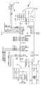
Figures 2a to 2e are diagrams of an inductive power supply circuit.
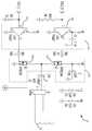
Figures 3a and 3b are views of an auxiliary power circuit.
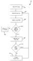
4 is a flow chart of a method of operating an inductive power supply circuit.
5 is a flowchart of a method of operating a secondary power supply circuit.
Figure 6 is a representative power / frequency curve for an embodiment of the present invention.
7 is a representation of an amplitude modulated signal carrying data;
Figure 8 is a representation of data encoded using differential bi-phase encoding.
9 is a representation of a data packet;
10 is a schematic representation of a bank of series capacitors;
11 is a schematic representation of a bank of parallel capacitors.
Figure 12 is a schematic representation of an alternative embodiment of an auxiliary power circuit.
Figures 13a-13d are views of another alternative embodiment.
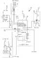
14A and 14B are views of another embodiment of an auxiliary power circuit.
I.개요I.Overview
본 발명의 실시예에 따른 유도 충전 시스템을 갖는 원격 제어 시스템(10)이 도 1에 도시된다. 상기 시스템은 일반적으로 유도 전력 공급 장치(12) 및 배터리로 동작되는 원격 제어 장치(14)를 포함한다. 유도 전력 공급 장치(12)는 원격 제어 장치(14)에게 무선으로 전력을 송신할 수 있는 전자기장을 생성한다. 원격 제어 장치(14)는 적절한 전자기장이 존재하는 경우에 전력을 수신하고 이를 사용 가능한 형태로 전달할 수 있는 2차 전력 공급 장치(60)를 포함한다. 2차 회로(60)에서 유도된 전력은 전하 저장 커패시터(72)에 고속으로 저장된다. 전하 저장 커패시터(72)에 저장된 전력은 배터리 충전에 적합한 장기간에 걸쳐 배터리(100)를 충전하는 데 사용된다. 따라서, 전력이 전하 저장 커패시터(72)에 빠르게 저장될 수 있고, 원격 제어 장치(14)가 유도 전력 공급 장치(12)로부터 제거된 후에도 배터리(100)를 계속 충전하는 데 사용될 수 있다. 일부 응용예들에서, 전하 저장 커패시터(72)에 저장된 전력은 원격 제어 장치(14)를 위한 단기적인 전원을 제공하는 데 사용될 수 있다. 예컨대, 일부 응용예들에서, 원격 제어 장치(14)는 전하 저장 커패시터(72)로부터 직접 전력을 인출할 수 있다. 이러한 실시예들에서, 원격 제어 장치(14)는 시스템이 배터리 충전에만 의존하는 경우에 필요한 것보다 훨씬 더 빠르게 작동하기에 충분한 정도로 충전될 수 있다.A
II.구조II.rescue
위에서 주목한 바처럼, 원격 제어 시스템(10)은 원격 제어 장치(14)와 같은 적절한 원격 장치에서 전력을 유도할 수 있는 전자기장을 생성하는 유도 전력 공급 장치(12)를 포함한다. 특정한 유도 전력 공급 장치(12)와 관련하여 기술되지만, 본 발명은 필요한 전력을 전달할 수 있는 실질적으로 임의의 유도 전력 공급 장치와 함께 사용되도록 구성될 수 있다. 이제 도 1을 참조하면, 도시된 실시예의 유도 전력 공급 장치(12)는 일반적으로 제어기(32) 및 탱크(tank) 회로(34)를 포함한다. 이러한 실시예의 제어기(32)는 상이한 동작 주파수에서 탱크 회로(34)에 전력을 공급할 수 있는데, 이는 제어기(32)가 원격 제어 장치(14)에 제공되는 전력을 변화시킬 수 있도록 한다. 대안적인 실시예들에서, 제어기(32)는 동작 주파수 대신, 또는 그에 부가하여 듀티 사이클을 변화시킬 수 있다. 이러한 실시예의 탱크 회로(34)는 1차 코일(16) 및 커패시터(38)를 갖는 직렬 공진 탱크 회로이다. 탱크 회로(34)는 그 대신 병렬 공진 탱크 회로들과 같은 다른 형태의 공진 및 비공진 탱크 회로들일 수 있다. 이러한 실시예의 유도 전력 공급 장치(12)는 외부 DC 전력 공급 장치(22)로부터 전력을 수신한다. 외부 DC 전력 공급 장치(22)는 110V AC 입력을 수신하고 19V DC에서 출력 전력을 제공할 수 있는 종래의 DC 전력 공급 장치일 수 있다.As noted above, the
본 발명의 실시예에 따른 유도 전력 공급 장치(12)의 회로도가 도 2a 내지 2e에 도시된다. 도 2a 내지 2e에 도시되지 않지만, 유도 전력 공급 장치(12)는 외부 DC 전력 공급 장치(22)로부터 VIN에서 전력을 수신한다(도 1 참조). 유도 전력 공급 장치(12)는 일반적으로 제어기(32), 메모리(40), 전력 공급 장치(42), 클록(44), IRDA 부회로(46), 포트(48), 드라이버 전자 소자들(50a 및 50b), FET들(52a 및 52b), 1차 코일(16), 탱크 커패시터(38), 전류 감지 변성기(current sense transformer) 부회로(54), LED(56) 및 LED 전력 부회로(58)를 포함한다. 전력 공급 장치(42)는 제어기(32) 및 회로의 다른 컴포넌트들을 위한 DC 전력을 제공하고, VIN을 적절한 DC 전압 VCC로 변환하는 종래의 DC/DC 전력 공급 장치일 수 있다. 전력 공급 장치(42)의 출력은 원하는 경우 필터링 커패시터들(43)의 배열을 통해 제어기(32)에 제공될 수 있다. 메모리(40)는 다른 것들 중에서도 유도 전력 공급 장치(12)의 동작 프로그램 및 동작 파라미터들을 저장하는 데 사용될 수 있다. 메모리(40)는 임의의 적합한 메모리일 수 있지만, 도시된 실시예에서는 64k의 종래의 EEPROM이다. 상기 회로는 제어기(32) 내에 통합된 내부 RC 상수 클록에 비해 향상된 정밀도를 제공하기 위한 외부 클록(44)을 포함할 수 있다. 외부 클록(42)은 종래의 수정 발진기 클록일 수 있다. 제어기(32)는 스위칭 회로(53)의 타이밍을 제어하는 드라이버 회로(51)에게 제어 신호들을 출력한다. 드라이버 회로(51)는 드라이버 전자 소자들(50a 및 50b)을 포함하고, 스위칭 회로(53)는 FET들(52a 및 52b)을 포함한다. 드라이버 전자 소자들(50a 및 50b)에 대한 제어 신호들의 타이밍은 FET들(52a 및 52b)의 타이밍을 제어하고, 그 결과 탱크 회로(34)의 동작 주파수를 제어한다. 보다 구체적으로, 제어 신호들은 드라이버 전자 소자들(50a 및 50b)에 의해 FET들(52a 및 52b)을 동작시키기에 충분한 진폭으로 증폭된다. 제어기(32)는 원하는 동작 주파수로 탱크 회로(34)를 VIN 또는 접지에 교대로 접속시키도록 FET들(52a 및 52b)을 교대로 열고 닫는 제어 신호들을 생성한다. 제어기(32)는 제어 신호들의 타이밍을 변화시켜 유도 전력 공급 장치(12)의 동작 주파수 및/또는 듀티 사이클을 변화시킬 수 있다.A circuit diagram of the
도시된 실시예에서, 1차 코일(16)은 리츠선(Litz wire)과 같은 선의 코일이다. 1차 코일(16)의 특성들(예컨대 선 크기, 선 유형, 권선수, 코일의 모양)은 원하는 기능을 달성하도록 응용예마다 달라질 것이다. 1차 코일(16)은 자기장을 생성할 수 있는 실질적으로 임의의 컴포넌트일 수 있다. 예컨대, 1차 코일(16)은 인쇄 회로 기판(printed circuit board) 코일 또는 스탬프 코일(stamped coil)로 대체될 수 있다.In the illustrated embodiment, the
도시된 실시예의 탱크 커패시터(38)는 1차 코일(16)과 결합되는 경우 동작 주파수들의 예상 범위에서 또는 그 근처에서 탱크 회로에게 공진 주파수를 제공하는 커패시턴스를 갖도록 선택된다. 탱크 커패시터(38)의 특성들은 원하는 바에 따라 응용예마다 달라질 수 있다.The
전류 감지 변성기 부회로(54)는 탱크 회로(34)에 결합되어 탱크 회로(34) 내의 전류를 나타내는 신호를 제어기(32)에게 제공한다. 도시된 실시예에서, 전류 감지 변성기 부회로(54)는 전류 감지 변성기(55)를 포함하는데, 이것의 출력은 제어기(32)에 도달하기 전에 도 2a 내지 2e에 도시된 바와 같은 다양한 컨디셔닝(conditioning) 및 필터링 컴포넌트를 통과한다. 전류 감지 변성기 부회로(54)의 출력은 전자기장 상에서 운반되는 데이터 신호들을 복조할 뿐만 아니라(아래에서 더 상세히 기술됨) 초과 전력 인출과 같은 고장 상태를 식별하도록 제어기(32)에 의해 사용될 수 있다. 고장 상태가 발생할 경우, 제어기(32)는 예컨대 고장 상태를 해결하기 위한 노력으로서 시스템을 차단하거나 이것의 동작 파라미터들을 변화시킴으로써 복구 조치를 취할 수 있다.The current
도시된 실시예는 선택적인 IRDA 부회로(46) 및 선택적인 프로그래밍 포트(48)를 포함한다. IRDA 부회로(46) 및 포트(48)는 제어기(32)를 프로그래밍하고 업그레이드하기 위한 대안들이다. IRDA 부회로(46)는 종래의 IRDA 통신을 사용하여 제어기(32)가 프로그래밍되거나 업그레이드될 수 있도록 하고, 포트(48)는 제어기(32)가 플러그인 접속(plugged-in connection)을 통해 프로그래밍되거나 업그레이드될 수 있도록 한다.The illustrated embodiment includes an
원격 제어 장치(14)는 유도 전력 공급 장치(12)로부터 전력을 수신하고 전력을 사용하여 전하 저장 커패시터(72)를 고속으로 충전하는 보조 전력 회로(60)를 포함하는, 배터리로 동작되는 원격 제어 장치이다. 예컨대, 일 실시예에서, 원격 제어 장치(14)는 원격으로 텔레비전의 채널을 변경하기 위한 텔레비전 원격 제어 장치일 수 있다. 보조 전력 회로(60)는 전하 저장 커패시터(72)에 저장된 전력을 활용하여 적절한 기간에 걸쳐 원격 제어 장치(14)의 배터리(100)를 충전한다. 도시된 실시예에서, 보조 전력 회로(60)는 일반적으로 2차 코일(62), 정류기(64), 충전 스위치(66), 전류 감지 증폭기 부회로(68), 전압 감지 부회로(70), 전하 저장 커패시터(72), VCC 조정기(regulator) 부회로(74), 승압(voltage boost) 부회로(76), 스위치 드라이버 부회로(78), 제어기(80), 통신 부회로(82), 온도 감지 부회로(84) 및 A/D 전압 기준 부회로(86)를 포함한다. 도시된 실시예에서, 2차 코일(62)은 일반적으로 리츠선과 같은 선으로 된 종래의 중앙 탭(center-tapped) 코일이다. 2차 코일(62)의 특성들(예컨대 선 크기, 선 유형, 권선수, 코일의 모양)은 원하는 기능을 달성하도록 응용예마다 달라질 것이다. 2차 코일(62)은 유도 전력 공급 장치(12)에 의해 생성되는 장과 같은 자기장의 존재 하에 전압이 유도되는 실질적으로 임의의 컴포넌트일 수 있다. 예컨대, 2차 코일(62)은 인쇄 회로 기판 코일 또는 스탬프 코일로 대체될 수 있다. 정류기(64)는 2차 코일(62)에서 유도된 AC 전력을 정류하여 DC 전력을 제공한다. 정류기(64)는 AC 전력을 DC 전력으로 변환할 수 있는 실질적으로 임의의 회로일 수 있지만, 도시된 실시예에서는 두 개의 다이오드(88a 및 88b)를 갖는 전파(full-wave) 정류기이다. 충전 스위치(66)는 정류기(64)로부터 전하 저장 커패시터(72)로의 DC 전력의 공급을 선택적으로 제어하도록 동작 가능하다. 충전 스위치(66)는 스위치 드라이버 부회로(78)의 동작에 의해 열리고 닫히는 FET일 수 있다. 스위치 드라이버 부회로(78)는 충전 스위치(66)의 동작을 제어할 수 있는 실질적으로 임의의 드라이버일 수 있다. 도시된 실시예에서, 스위치 드라이버 부회로(78)는 승압 부회로(76)와 협력하여 충전 스위치(66)를 동작시킨다. 도시된 실시예(78)의 스위치 드라이버 부회로(78)는 제어기(80)로부터의 제어 신호에 의해 작동되는 트랜지스터(90)를 포함한다. 트랜지스터(90)가 닫히는 경우, 승압 부회로(76)의 출력은 접지로 떨어지고, 그럼으로써 충전 스위치(66)를 연다. 도시된 실시예에서, 승압 부회로(76)는 2차 코일(62)로부터의 AC 전압을 더 높은 DC 전압으로 변환하는 종래의 전압 배율기(voltage doubler)이다. 승압 부회로(76)의 출력은 충전 스위치(66)를 동작시키도록 스위치 드라이버 부회로(78)에 의해 사용된다. 전류 감지 증폭기 부회로(68)는 전하 저장 커패시터(72)에 인가되는 전류를 측정한다.The
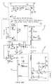
보조 전력 회로(60)는 전류 감지 및 전압 감지 회로를 포함한다. 보조 전력 회로의 일 실시예가 도 3a 및 3b에 도시된다. 이러한 부회로들은 다양한 동작을 위한 입력을 제공하지만, 충전 중에 전하 저장 커패시터(72)에 인가되는 전력의 양을 제어하고 전하 저장 커패시터(72)가 완전히 충전되는 때를 결정하는 데 주로 사용된다. 도시된 실시예의 전류 감지 증폭기 부회로(68)는 사실상 저항기(92)에 걸친 전압 강하를 측정하는 연산 증폭기를 갖는 일반적인 종래의 부회로이다. 전류 감지 증폭기 부회로(68)의 출력은 제어기(80)에 공급된다. 전압 감지 부회로(70)는 전하 저장 커패시터(72)에 인가되는 전압을 측정한다. 전압 감지 부회로(70)는 커패시터에 인가되는 전압을 나타내는 출력을 제공할 수 있는 임의의 회로일 수 있다. 도시된 실시예에서, 전압 감지 부회로(70)는 전하 저장 커패시터(72)가 충전되고 있지 않은 경우 부회로(70)를 선택적으로 비활성화시키기 위한 FET(94)을 포함한다. 이는 전하 저장 커패시터(72)가 충전되고 있지 않은 경우에 전압 감지 부회로(70)를 통해 전하 저장 커패시터(72)로부터 여분의 전력이 누출되는 것을 방지한다. 전압 감지 부회로(70)는 또한 제어기(80)에 대한 입력에 적합한 범위로 전압을 스케일링(scale)하기 위한 분압기(voltage divider)를 포함한다.The
전하 저장 커패시터(72)는 단일 커패시터 또는 커패시터들의 뱅크일 수 있다. 예컨대, 도 10은 직렬로 배열된 복수의 커패시터(72a 내지 72c)를 도시한다. 다른 예로서, 도 11은 병렬로 배열된 복수의 커패시터(72a 내지 72c)를 도시한다. 전하 저장 커패시터(72)의 특성들은 응용예마다 전력 요구 및 패키징 제약에 많은 부분을 의존하여 달라질 수 있다. 도시된 실시예에서, 전하 저장 커패시터(72)는 수퍼커패시터, 울트라커패시터(ultracapacitor) 또는 전기 화학적 이중층 커패시터이다. 일부 응용예들에서, 전하 저장 커패시터(72)는 하나 이상의 종래의 전해 커패시터일 수 있다.The
위에서 주목한 바처럼, 보조 전력 회로(60)는 제어기(80) 및 다른 컴포넌트들을 동작시키는 데 적합한 레벨로 DC 전압을 제공하기 위한 VCC 조정기 부회로(74)를 포함한다. VCC 조정기 부회로(74)는 원하는 DC 출력을 제공할 수 있는 실질적으로 임의의 부회로일 수 있다.As noted above, the
보조 전력 회로(60)는 A/D 전압 기준 부회로(86)를 포함한다. 이러한 부회로(86)는 안정적인 기준 전압을 생성할 수 있는 실질적으로 임의의 부회로일 수 있다. 도시된 실시예에서, A/D 전압 기준 부회로(86)는 기준 전압을 생성하기 위한 IC(93)를 포함한다. 그 대신, VCC 조정기 부회로(74)가 충분히 안정적인 전압을 제공하도록 구성되는 경우, A/D 전압 기준 부회로(86)는 제거될 수 있다.The auxiliary power circuit (60) includes an A / D voltage reference sub-circuit (86). This
보조 전력 회로(60)는 또한 2차 회로 내의 온도를 모니터링하고 온도 측정값을 제어기(80)에게 제공하는 온도 감지 부회로(84)를 포함할 수 있다. 온도 측정값이 미리 결정된 값을 초과하는 경우 제어기(80)는 보조 전력 회로(60)를 비활성화할 수 있다.The
보조 전력 회로(60)는 충전 회로(102)에 의해 배터리(100)에 결합된다. 사용시에, 배터리(100)는 원격 제어 장치(14)의 원격 제어 기능들에게 전력을 제공한다. 충전 회로(102)는 전하 저장 커패시터(72)에 저장된 전력을 사용하여 배터리(100)를 충전할 수 있는 실질적으로 임의의 회로일 수 있다. 일 실시예에서, 충전 회로(102)는 단순히 배터리를 전하 저장 커패시터(72) 및 접지에 접속시키는 전기적 접속기들이다. 다른 실시예에서, 충전 회로(102)는 전하 저장 커패시터(72)와 배터리(100) 사이에 배치되는 다이오드를 포함한다. 또 다른 실시예에서, 충전 회로(102)는 배터리 충전 IC를 포함할 수 있다. 다양한 배터리 충전 IC가 상업적으로 입수 가능하다. 예컨대, 종래의 리튬 이온 충전 프로파일(profile)에 따라 배터리(100)를 충전하기 위한 리튬 이온 충전 IC들이 상업적으로 입수 가능하다.The auxiliary power circuit (60) is coupled to the battery (100) by a charging circuit (102). In use, the
아래에서 더 상세히 기술되는 바처럼, 통신 부회로(82)는 전자기장 상에서 운반되는 데이터 통신을 생성하도록 디자인된다. 일반적으로, 통신 부회로(82)는 데이터를 표현하는 패턴으로 부하를 2차 코일에 선택적으로 인가함으로써 통신한다. 도시된 실시예에서, 통신 부회로(82)는 FET(96) 및 저항기(98)의 형태인 통신 부하를 포함한다. 동작시에, 제어기(80)는 FET(96)를 선택적으로 작동시켜 저항기(98)를 인가 및 제거한다. 이러한 부하의 존재 또는 부재는 반사된 임피던스를 통해 1차 회로에 전달되는데, 이는 다음으로 탱크 회로 내의 전류에 영향을 미친다. 예컨대, 2차 회로 내의 증가된 부하는 전형적으로 탱크 회로 내의 전류가 증가하는 결과를 낳는다. 통신 부회로의 부하가 충분히 상당한 경우, 1차 회로는 탱크 회로 내의 전류를 모니터링함으로써 2차 회로 내의 통신 부회로 부하의 존재 또는 부재를 구별할 수 있을 것이다. 통신 회로 부하의 "온" 및 "오프" 패턴들은 아래에서 더 상세히 기술되는 바처럼 1차 회로에 의해 인식될 수 있는 이진 데이터 스트림을 생성하는 데 사용될 수 있다. 도시된 실시예는 전자기장을 통해 데이터를 송신하는 통신 시스템을 포함하지만, 시스템(10)은 전자기장을 통해 통신하지 않는 통신 시스템들과 같은 대안적인 통신 시스템들을 포함할 수 있다. 예컨대, 시스템은 Bluetooth, WiFi 또는 전자기 코일들의 두 번째 쌍과 같은 외부 통신 시스템을 활용할 수 있다.As will be described in more detail below,
III.동작III.action
도시된 실시예에서, 유도 전력 공급 장치(12)의 동작 방법은 일반적으로 1) 호환 가능한 원격 제어 장치가 존재하는 때를 결정하는 단계, 2) 호환 가능한 원격 제어 장치가 존재하면 유도적으로 전력을 전송하는 단계, 3) 원격 제어 장치로부터의 피드백에 응답하여 동작을 조절하는 단계 및 4) 원격 제어 장치가 충전되면 유도 전력 전송을 중단하는 단계를 포함한다. 도시된 동작 방법은 향상된 효율 또는 향상된 성능을 제공할 수 있는 다양한 선택적인 단계를 포함한다. 동작 방법은, 선택적인 단계들의 제거를 포함하여, 원하는 바에 따라 응용예마다 달라질 수 있다.In the illustrated embodiment, the method of operation of the
도시된 실시예의 유도 전력 공급 장치(12)의 동작 방법(200)이 이제 도 4와 관련하여 기술될 것이다. 호환 가능한 원격 제어 장치가 존재하지 않는 경우에 시스템(10)에 의해 소비되는 에너지를 감소시키기 위해, 유도 전력 공급 장치(12)의 동작 방법은 전자기장 내에 적합한 원격 제어 장치(14)가 존재하는 때를 결정하기 위한 "핑잉(pinging)" 프로세스를 포함한다. 도 4에 도시된 바처럼, 유도 전력 공급 장치는 비교적 적은 양의 전력을 탱크 회로(34)에 주기적으로 인가함으로써 핑 상태(202)에 진입한다. 전형적으로 각 핑에서의 전력량은 소모된 배터리(100)를 갖는 원격 제어 장치(14)가 전자기장 내의 자신의 존재를 식별시키기 위한 피드백 신호를 생성하도록 하기에 충분하다. 그 대신, 핑은 더 적은 양의 전력을 포함할 수 있고, 전력은 시간에 따라 전하 저장 커패시터(72) 또는 배터리(100) 내에 축적되어 종국적으로 원격 제어 장치(14)가 자신을 유도 전력 공급 장치(12)에게 식별시키기에 충분한 전력을 제공할 수 있다. 피드백 신호 및 다른 통신의 성질 및 내용은 아래에서 더 상세히 논의된다. 유도 전력 공급 장치(12)는 원격 제어 장치(14)로부터의 통신에 관해 탱크 회로(34) 내의 전류를 모니터링하여 호환 가능한 원격 제어 장치(14)가 존재하는 때를 결정한다(204). 위에서 주목한 바처럼, 제어기(32)는 전류 감지 변성기 부회로(54)를 통해 통신을 모니터링한다.A
호환 가능 원격 제어 장치(14)의 존재를 나타내는 통신 신호가 수신되는 경우, 유도 전력 공급 장치(12)는 특정한 시작 주파수에서 유도 전력 전송을 개시한다(206). 이러한 시작 주파수는 유도 전력 공급 장치(12) 내의 메모리에 저장될 수 있거나, 또는 예컨대 핑에 응답하여 원격 제어 장치(14)에 의해 생성되는 피드백 신호 내에서 원격 제어 장치(14)에 의해 유도 전력 공급 장치(12)에게 통신될 수 있다.When a communication signal indicating the presence of the compatible
유도 전력 공급 장치(12)는 지정된 기간 동안에 시작 주파수에서 유도 전력 전송을 계속한다. 이러한 기간은 유도 전력 공급 장치(12) 내의 메모리에 저장되거나 원격 제어 장치(14)에 의해 유도 전력 공급 장치(12)에 통신될 수 있다. 예컨대, 기간의 길이는 핑에 응답하여 원격 제어 장치(14)에 의해 생성되는 피드백 신호 내에 내장(embed)될 수 있다. 지정된 기간이 경과한 후에 유도 전력 공급 장치(12)가 원격 제어 장치(14)로부터 피드백 신호를 수신하지 않은 경우, 유도 전력 공급 장치(12)는 원격 제어 장치(14)에 공급되는 전력을 증가시키도록 자신의 동작 주파수를 조절한다. 도시된 실시예에서, 유도 전력 공급 장치(12)는 탱크 회로(34)의 공진 주파수보다 높게 동작한다(도 6 참조). 따라서, 주파수의 감소는 유도 전력 공급 장치(12)를 공진에 더 가깝게 할 것이고, 원격 제어 장치(14)에 제공되는 전력을 증가시킬 것인데, 이는 도 6에서 점점 더 높아지는 주파수들 A, B, C 및 D에서 전력 레벨을 비교함으로써 확인될 수 있다. 그 결과, 지연 기간의 끝까지 피드백 신호가 수신되지 않는 경우, 유도 전력 공급 장치(12)는 자신의 동작 주파수를 감소시킬 것이다(210). 도 6에 도시된 전력/주파수 곡선에서, 주파수는 x축을 따라 양의 x 방향으로 이동함에 따라 증가하고, 전력은 y축을 따라 양의 y 방향으로 이동함에 따라 증가한다.The
한편, 원격 제어 장치(14)로부터 피드백 신호가 수신되는 경우, 유도 전력 공급 장치(12)는 피드백 신호를 분석하여 신호의 내용을 결정한다. 피드백 신호가 유도 전력 공급 장치(12)에게 충전을 중단하도록 지시하는 경우(212), 유도 전력 공급 장치(12)는 유도 전력 전송을 중단하고(214) 핑 상태(202)로 돌아간다.On the other hand, when a feedback signal is received from the
그렇지 않은 경우, 유도 전력 공급 장치(12)는 피드백 신호를 분석하고 통신에 따라 유도 전력 공급 장치(12)를 조절한다. 도시된 실시예에서, 시스템(10)은 전하 저장 커패시터(72)에게 고정된 양의 전력을 공급하도록 시도한다. 아래에서 더 상세히 기술되는 바처럼, 2차 회로(60)는 전하 저장 커패시터(72)에 인가되는 전력을 모니터링하고, 원하는 전력을 제공하도록 유도 전력 공급 장치(12)가 자신의 동작을 변화시키게 하는 피드백 신호들을 제공한다. 이러한 실시예에서, 유도 전력 공급 장치(12)는 2차 회로(60)가 전력이 원하는 레벨에 있음을 나타낼 때까지 전력을 증가시킨다. 다음으로 2차 회로(60)는 유도 전력 공급 장치에게 이것의 전력 레벨을 증가시키는 것을 중단하도록 지시하는 피드백 신호를 제공한다. 이러한 실시예는 동작 주파수를 조절하여 전력 레벨을 제어하므로, 피드백 신호는 실질적으로 유도 전력 공급 장치에게 이것의 동작 주파수를 감소시키는 것을 중단하도록 지시한다. 유도 전력 공급 장치(12)는 자신의 동작 주파수를 증가시키고(216), 지정된 지연 기간 후에(217) 단계 208로 돌아간다. 전력이 원하는 충전 레벨 이상에 있거나 전하 저장 커패시터(72)가 완전히 충전되었음을 나타내는 피드백 신호의 제공을 2차 회로(60)가 중단할 때까지 유도 전력 공급 장치(12)는 자신의 동작 주파수를 계속 증가시킬 것이다. 조절 간의 지연 길이와 조절의 크기는 원하는 바에 따라 응용예마다 달라질 수 있다. 이러한 값들은 유도 전력 공급 장치(12)의 내부 메모리에 저장되거나 원격 제어 장치(14)에 의해 유도 전력 공급 장치(12)에게 통신될 수 있다. 예컨대, 지연은 핑에 응답하여 원격 제어 장치(14)에 의해 생성되는 피드백 신호 내에 내장될 수 있다.Otherwise, the
확인할 수 있는 바처럼, 피드백 신호들은 이 실시예에서 유도 전력 공급 장치(12)의 동작을 구동시킨다. 피드백 신호가 수신되지 않는 경우, 유도 전력 공급 장치(12)는 주기적이고 반복적으로 동작 주파수를 감소시킨다(예컨대 단계 208 및 210). 피드백 신호가 충전 전력이 원하는 값에 있음을 나타내는 경우, 유도 전력 공급 장치(12)는 주기적이고 반복적으로 동작 주파수를 증가시킨다(예컨대 단계 208 및 216). 피드백 신호가 전하 저장 커패시터(72)가 완전히 충전되었음을 나타내는 경우, 유도 전력 공급 장치(12)는 유도 전력 전송을 중단하고(214) 핑 상태(202)로 돌아간다(예컨대 단계 208, 212 및 214). 이러한 방식으로, 호환 가능한 원격 제어 장치(14)(또는 다른 원격 장치)가 존재할 때까지 유도 전력 공급 장치(12)는 저전력 핑 상태에 머무른다. 이후 유도 전력 공급 장치(12)는 원격 제어 장치(14)에게 유도적으로 전력을 공급하면서, 커패시터가 완전히 충전될 때까지 원격 제어 장치(14)로부터의 피드백에 기초하여 비교적 일정한 전력 레벨을 유지하도록 자신의 동작 파라미터들을 조절한다.As can be seen, the feedback signals drive the operation of the
보조 전력 회로(60)의 동작 방법(250)이 주로 도 5를 참조하여 기술된다. 일반적으로, 보조 전력 회로(60)는 유도 전력 공급 장치(12)로부터 전력을 수신하고 그 전력을 활용하여 전하 저장 커패시터(72)를 충전한다. 보조 전력 회로(60)는 전하 저장 커패시터(72) 내의 전력을 사용하여 배터리(100)를 충전하고, 커패시터 내의 전력이 원격 제어 장치(14)를 동작시키는 데에 사용될 수 있도록 만들 수 있다. 보조 전력 회로(60)는 충전 프로세스를 모니터링하고 피드백 신호들을 유도 전력 공급 장치(12)에 송신하여 유도 전력 공급 장치(12)의 동작 파라미터들을 제어한다.The
보조 전력 회로(60)는 유도 전력 공급 장치(12)에 의해 송신되는 핑의 존재시에 "깨어난다". 깨어나면, 보조 전력 회로(60)는 다시 유도 전력 공급 장치(12)에게 식별 신호를 송신한다(252). 다른 부분에서 기술되는 바처럼, 보조 전력 회로(12)는 통신 부하(98)를 2차 코일(62)에게 선택적으로 인가함으로써 피드백 신호들을 생성한다. 제어기(80)는 아래에서 더 상세히 기술되는 통신 프로토콜에 따라 전자기장에서 데이터 스트림을 생성하도록 FET(96)를 선택적으로 열고 닫는다. 도시된 실시예에서, 데이터는 데이터 패킷들 내에서 유도 전력 공급 장치(12)에게 송신된다. 데이터 패킷을 생성하기 전에, 제어기(80)는 2차 코일(62)로부터 전하 저장 커패시터(72)를 분리시킨다. 보조 전력 회로(60)는 스위치 드라이버 부회로(78)를 통해 전하 저장 커패시터(72)를 분리시킨다. 제어기(80)는 트랜지스터(90)를 닫는 신호를 출력하고, 그럼으로써 승압 부회로(76)의 출력을 접지로 떨어뜨리고, 다음으로 이는 충전 스위치(66)를 연다. 열리면, 전하 저장 커패시터(72)는 2차 코일(62) 및 통신 부하(98)로부터 효과적으로 격리된다. 충전 스위치(66)는 데이터 패킷을 송신하기에 충분한 기간 동안 열려 있다. 데이터 패킷이 송신된 후에, 충전 스위치(66)는 다시 닫혀 전력이 전하 저장 커패시터(72)로 흐르도록 한다. 위에서 주목한 바처럼, 유도 전력 공급 장치(12)는 유도 전력 공급을 개시함으로써 식별 신호에 응답한다.The
유도 전력 공급이 진행중인 동안에, 보조 전력 회로(60)는 전하 저장 커패시터(72)의 전압을 주기적으로 또는 지속적으로 모니터링하고(254), 커패시터(72)에 인가되는 전류를 주기적으로 또는 지속적으로 모니터링한다(256). 보다 구체적으로, 전압 감지 부회로(70)는 전하 저장 커패시터(72)의 전압을 나타내는 신호를 제어기(80)에게 제공한다. 감지된 전압이 최대 용량 이상인 경우(258), 보조 전력 회로(60)는 전하 저장 커패시터(72)가 완전히 충전되었음을 나타내는 데이터 패킷을 유도 전력 공급 장치(12)에게 송신하는데(260), 이는 위에서 논의된 바처럼 유도 전력 공급 장치가 유도 전력 전송을 중단하고 핑 상태로 돌아가도록 야기한다. "완충(fully charged)" 데이터 패킷이 송신되는 동안에 충전 스위치(66)는 열려 있다. 감지된 전압이 최대 용량 미만인 경우, 제어기(80)는 전류 감지 증폭기 부회로(68) 및 전압 감지 부회로(70)로부터의 신호들에 기초하여 커패시터 충전 전력을 계산한다(262). 전력이 원하는 충전 전력 이상인 경우(264), 보조 전력 회로(60)는 전력이 원하는 값 이상임을 나타내는 데이터 패킷을 유도 전력 공급 장치(12)에게 송신한다(266). 다시, 데이터 패킷이 송신되는 동안에 충전 스위치는 열려 있다. "충전중(at charging power)" 데이터 패킷이 아래에서 논의되는 통신 방법에 따라 송신된다. 위에서 주목한 바처럼, 유도 전력 공급 장치(12)는 유도 전력 공급 장치(12)의 동작 주파수를 증가시킴으로써 이러한 데이터 패킷에 응답하는데, 이는 동작 주파수를 공진으로부터 멀어지게 하고 2차 코일(62)에 공급되는 전력을 감소시킨다. 보조 전력 회로(60)는 계산된 전력이 미리 결정된 충전 전력 이상에 머무르는 동안에는 "충전중" 신호를 주기적으로 계속 송신할 것이다.While the inductive power supply is in progress, the
충전 전력이 원하는 문턱값 미만으로 떨어지면, 보조 전력 회로(60)는 "충전중" 신호의 송신을 중단할 것이다. 이러한 신호의 부재는 유도 전력 공급 장치(12)가 동작 주파수를 주기적이고 반복적으로 감소시키기 시작하도록 야기하고, 그럼으로써 커패시터 충전 전력이 다시 원하는 문턱값에 도달할 때까지 순차적으로 커패시터 충전 전력을 증가시키도록 한다. 확인할 수 있는 바처럼, 도시된 실시예의 보조 전력 회로(60)는 원하는 커패시터 충전 전력을 유지하도록 동작 파라미터들을 조절하고 전하 저장 커패시터(72)가 완전히 충전되면 유도 전력 전송을 중단하도록 유도 전력 공급 장치(12)에게 지시하는 피드백 신호들을 생성한다.If the charge power falls below a desired threshold, the
도시된 실시예에서, 2차 코일에 공급되는 전력은 탱크 회로(34)에 공급되는 전력의 동작 주파수에 대한 조절을 통해 변화된다. 동작 주파수 조절은 원하는 경우 전력을 변화시키기 위한 다른 메커니즘들로 대체되거나 보충될 수 있다. 예컨대, 유도 전력 공급 장치는 (동작 주파수를 변화시키는 대신에 또는 그에 부가하여) 탱크 회로(34)에 인가되는 신호의 듀티 사이클을 변화시킴으로써 전력을 제어하도록 구성될 수 있다. 입력 DC 전압 레일은 주파수가 일정하게 유지되는 동안에 변화될 수 있다.In the illustrated embodiment, the power supplied to the secondary coil is varied through adjustment to the operating frequency of the power supplied to the
위에서 논의된 바처럼, 도시된 실시예의 보조 전력 회로(60)는 유도 전력 공급 장치(12)의 동작에 관한 소정의 국면들을 제어하는 데 유용한 통신을 유도 전력 공급 장치(12)에게 송신한다. 본 발명은 보조 전력 회로(60)로부터 유도 전력 공급 장치(12)로 통신을 제공할 수 있는 실질적으로 임의의 통신 시스템을 사용할 수 있다. 도시된 실시예에서, 통신은 전자기장 상에서 운반되는 피드백 신호들의 형태로 송신된다. 이는 통신이 2차 코일(62)로부터 1차 코일(16)로 전달될 수 있도록 하고, 그럼으로써 추가적인 통신 컴포넌트들에 대한 필요를 없앤다. 통신을 전자기장에 내장시키기 위한 방법은 응용예마다 달라질 수 있지만, 도시된 실시예의 통신 시스템은 디지털 2상 인코딩 및 후방 산란(backscatter) 변조 기술을 사용한다. 이러한 응용예에서, 데이터는 보조 전력 회로(60)에 의해 RF 장 위로 후방 산란 변조에 의해 변조된다. 이는 비교적 큰 부하(저항기 98)를 2차 코일(62)에 대해 "켜고" "끔"으로써 통신 부회로(82)를 통해 이루어질 수 있다. 이러한 부하를 "켜고" "끄는" 것은 보조 전력 회로(60)의 임피던스 변화를 야기하는데, 이는 반사된 임피던스에 의해 1차 코일(16)에 전달된다. 이러한 반사된 임피던스의 변화는 유도 전력 공급 장치 측에서 탱크 회로(34) 내의 전류 변화로서 탐지된다. 신호의 진폭 증가가 도 7의 영역 120 및 122에 의해 도시된다. 탱크 회로(34) 내의 전류를 모니터링함으로써, 유도 전력 공급 장치(12)는 전자기장 상에서 운반되는 데이터 신호들을 복조할 수 있다. 따라서, 통신 부회로(82)는 보조 전력 회로(60)로부터 유도 전력 공급 장치(12)로 데이터를 송신하는 데 사용될 수 있는 진폭 변조된 신호를 생성한다.As discussed above, the
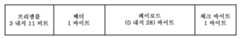
본 발명은 데이터 비트들을 인코딩하기 위한 실질적으로 임의의 방법을 활용할 수 있다. 도시된 실시예에서, 보조 전력 회로(60)는 차등 2상 인코딩 기법을 사용하여 데이터 비트들을 생성한다. 이 기법은 천이(transition)에 기초하고, 에지(edge)가 매 클록 에지에서 발생한다. 데이터 비트들은 클록 주기 중의 천이의 존재 또는 부재에 의해 구별된다. 천이가 클록 주기 중에 발생하는 경우 데이터 비트는 "1"이고, 그렇지 않은 경우 데이터 비트는 "0"이다. 인코딩 기법은 천이에 기초하므로, 이는 데이터 변조에 의해 사용되는 "0"들과 "1"들의 극성에 대해 독립적이다. 데이터 바이트들은 표준 비동기 직렬 형식, 즉 1개의 시작 비트, 8개의 데이터 비트(LSB 우선), 1개의 홀수 패리티 비트 및 1개의 정지 비트를 사용하여 형식화될 수 있다. 이러한 실시예에서, 시작 비트는 "0"이고 정지 비트는 "1"이다. 도 8은 차등 2상 인코딩을 사용하여 인코딩된 데이터의 대표적인 도시이다. 도시된 실시예에서, 데이터는 패킷 형식으로 보조 전력 회로(60)로부터 유도 전력 공급 장치(12)로 송신된다. 패킷은 프리앰블(preamble), 헤더 바이트, 페이로드(payload) 바이트들(선택적) 및 검사 바이트(도 9 참조)로 이루어질 수 있다. 각 바이트는 도 9에 도시된 바처럼 11개의 비트로 이루어질 수 있다. 이 실시예에서, 프리앰블을 포함하는 전체 패킷은 31 바이트까지의 길이를 갖는다. 프리앰블은 유도 전력 공급 장치가 들어오는 데이터를 동기화할 수 있도록 하고, 데이터의 제1 바이트의 시작 비트를 정확히 결정할 수 있도록 한다. 이러한 실시예의 프리앰블은 적어도 3개의 비트(이 경우에는 모두 "1"임)로 이루어질 수 있지만, 이 실시예에서는 표준 UART가 통신을 구동시키고 프리앰블을 송신할 수 있도록 11 비트만큼 길 수 있다. 헤더는 패킷의 유형을 정의하는 단일 바이트이다. 패킷 유형 필드는 패킷의 길이를 결정하는 데 사용될 수 있다. 페이로드는 패킷으로 통신되는 주요 데이터를 포함한다. 패킷 유형은 페이로드의 내용 및 크기를 지시할 수 있다. 패킷은 수신된 데이터 패킷을 인증하기 위한 방식으로서 검사 바이트를 포함할 수 있다. 오류 탐지를 가능하게 하도록 검사 바이트가 매 패킷의 끝에 추가될 수 있다. 검사 바이트는 헤더에서부터 페이로드 바이트들의 마지막 바이트까지의 모든 바이트들을 "배타적 논리합(Exclusive OR)"함으로써 생성될 수 있다. 도시된 실시예에서, 프리앰블은 검사 바이트 계산에 포함되지 않는다. 본 발명이 특정한 통신 시스템에 관하여 상세히 기술되지만, 본 발명은 보조 전력 회로(60)로부터 유도 전력 공급 장치(12)로 데이터를 통신하는 데 적합한 실질적으로 임의의 통신 시스템을 활용할 수 있다.The present invention may utilize substantially any method for encoding data bits. In the illustrated embodiment, the
일부 응용예들에서, 통신 시스템은 전부 제거될 수 있다. 예컨대, 본 발명은 충전 제어가 보조 전력 회로 내에서만 수행되는 간단한 아날로그 회로로 구현될 수 있다. 이제 도 12를 참조하면, 아날로그로 구현한 보조 전력 회로(60')는 일반적으로 2차 코일(62'), 다이오드(64')(정류를 위한 것임), 충전 스위치(66'), 전압 감지 부회로(70'), 전하 저장 커패시터(72'), 배터리(100') 및 충전 회로(102')를 포함할 수 있다. 동작시에, 2차 코일(62')은 유도 전력 공급 장치(도시되지 않음)로부터 유도적으로 전력을 수신한다. 유도된 전력은 다이오드(64')에 의해 정류된다. 정류된 전력은 충전 스위치(66')의 상태에 따라 전하 저장 커패시터(72')에 인가될 수 있다. 충전 스위치(66')는 전압 감지 부회로(70')의 동작을 통해 열리고 닫힌다. 전하 저장 커패시터(72')가 완전히 충전되는 경우, 전압 감지 부회로(70')는 전하 저장 커패시터(72')를 2차 코일(62')로부터 실질적으로 분리시키도록 충전 스위치(66')를 연다. 전하 저장 커패시터(72')가 완전히 충전되지 않은 경우, 전압 감지 부회로(70')는 추가적인 충전을 가능하게 하도록 충전 스위치(66')를 닫는다. 전하 저장 커패시터(72') 내의 전력은 충전 회로(102')를 통해 배터리(100')에 인가된다. 도시된 실시예에서, 충전 회로(102')는 단순히 전하 저장 커패시터(72')로부터 배터리(100')로의 전기적 접속부이다.In some applications, the communication system may be eliminated altogether. For example, the present invention can be implemented with a simple analog circuit in which charge control is performed only within the auxiliary power circuit. Referring now to FIG. 12, an analog implemented auxiliary power circuit 60 'generally includes a secondary coil 62', a diode 64 '(for rectification), a charge switch 66' A sub-circuit 70 ', a charge storage capacitor 72', a battery 100 'and a charging circuit 102'. In operation, the secondary coil 62 'receives power inductively from an inductive power supply (not shown). The induced power is rectified by diode 64 '. The rectified power may be applied to the charge storage capacitor 72 'according to the state of the charge switch 66'. The charging switch 66 'is opened and closed through the operation of the
보조 전력 회로의 다른 예시적인 실시예가 도 14a 및 14b의 회로도에 도시된다. 이 회로는 도 3a 및 3b에 도시된 보조 전력 회로에 포함된 것과 유사하다. 회로 전반에 걸쳐 사용된 컴포넌트들에 있어서 일부 차이가 존재한다. 예컨대, 마이크로프로세서를 사용하는 상이한 VCC 조정기 부회로(74')가 도 3a 및 3b의 실시예에서 사용된 VCC 조정기 부회로를 대체한다. 또한, 상이한 스위칭 소자들이 회로 전반에 걸쳐, 예컨대 충전 스위치(66') 및 스위치 드라이버 부회로(78')에서 사용된다. 일부 컴포넌트들은 보조 전력 회로 내의 상이한 위치들에 배치되는데, 예컨대 전류 감지 증폭기(68')는 도 14a 및 14b의 실시예에서 울트라커패시터의 맞은 편 단자 상에 배치된다. 도 14a 및 14b의 실시예에서, 온도 센서가 보조 전력 회로로부터 제거된다. 이러한 차이는 대체로 디자인 선택 및 특정한 응용예에 대한 최적화의 결과이다. 다른 실시예들에서는 상이한 컴포넌트들 및 회로 배열들이 적합할 수 있다.Other exemplary embodiments of the auxiliary power circuit are shown in the circuit diagrams of Figs. 14A and 14B. This circuit is similar to that included in the auxiliary power circuit shown in Figs. 3A and 3B. There are some differences in the components used throughout the circuit. For example, a different VCC regulator subcircuit 74 'using a microprocessor replaces the VCC regulator subcircuit used in the embodiment of FIGS. 3A and 3B. In addition, different switching elements are used throughout the circuit, for example, in the charging switch 66 'and the switch driver subcircuit 78'. Some components are disposed at different locations within the auxiliary power circuit, e.g., current sense amplifier 68 'is disposed on the opposite terminal of the ultracapacitor in the embodiment of Figs. 14A and 14B. In the embodiment of Figures 14A and 14B, the temperature sensor is removed from the auxiliary power circuit. These differences are largely the result of design choices and optimization for specific applications. In other embodiments, different components and circuit arrangements may be suitable.
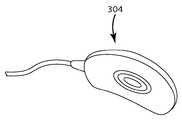
원격 제어 장치(14)와 관련하여 기술되지만, 본 발명은 다양한 배터리 전원 전자 장치와 관련하여 사용되기에 적합하다. 예컨대, 본 발명은 스마트폰, 휴대 전화, 미디어 플레이어, PDA(Personal Digital Assistant) 및 다른 휴대용 전자 장치로 구현될 수 있다. 본 발명은 또한 유도 충전 이식 가능 의료 장치들로 구현될 수 있다. 예컨대, 도 13a 내지 13d는 배터리 전원 이식 가능 의료 장치로 구현되는 본 발명의 실시예를 도시한다. 본 발명은 배터리 충전을 위해 사람이 움직이지 않고 있어야 하는 시간의 양을 극적으로 감소시킬 수 있기 때문에 이식 가능 의료 장치 응용예들에 있어서 특히 유익하다. 이러한 실시예의 의료 장치 시스템(300)은 일반적으로 이식 가능 의료 장치(302)(이 경우 심박 조율기), 핸드헬드(hand-held) 유도 전력 공급 장치(304) 및 보조 전력 회로(306)를 포함한다. 앞서 기술된 실시예들과 마찬가지로, 보조 전력 회로(306)는 2차 코일(308), 전하 저장 커패시터(310), 충전 회로(도시되지 않음) 및 배터리(314)를 포함할 수 있다. 2차 코일(308)은 외부 유도 전력 공급 장치로부터 유도 전력을 손쉽게 수신할 수 있는 피부 바로 아래에 배치될 수 있다. 동작시에, 내장된 전하 저장 커패시터(310)를 고속으로 충전하기 위해, 핸드헬드 장치(304)가 사용자에 의해 2차 코일(308)위에 배치될 수 있다. 충전된 전하 저장 커패시터(310) 내의 전력은 배터리(314)를 충전하거나 또는 의료 장치(302)에 직접 전력을 공급하는 데 사용될 수 있다. 의료 장치 시스템(300)은 원하는 경우 통신 시스템을 포함할 수 있다.Although described in connection with the
위의 설명은 본 발명의 현재의 실시예에 관한 것이다. 본 발명의 사상 및 더 넓은 태양들로부터 벗어나지 않고 다양한 개변 및 변경이 이루어질 수 있다.The foregoing description is of a current embodiment of the invention. Various modifications and alterations can be made without departing from the spirit and broader aspects of the invention.
10: 원격 제어 시스템
12: 유도 전력 공급 장치
14: 원격 제어 장치
22: 전력 공급 장치
32: 제어기
34: 탱크 회로10: Remote control system
12: Inductive power supply
14: Remote control device
22: Power supply
32:
34: tank circuit
Claims (43)
Translated fromKorean무선 전력을 공급하기 위한 유도 전력 공급 장치; 및
상기 유도 전력 공급 장치로부터 분리 가능한 원격 장치
를 포함하고,
상기 원격 장치는 보조 전력 회로(secondary power circuit), 전하 저장 커패시터, 충전 부회로 및 배터리를 포함하고,
상기 보조 전력 회로는 상기 전하 저장 커패시터에 전기적으로 접속되고, 상기 보조 전력 회로는 상기 유도 전력 공급 장치로부터 무선 전력을 수신하고 상기 전하 저장 커패시터를 고속으로 충전하도록 구성되고,
상기 충전 부회로는 상기 전하 저장 커패시터 및 상기 배터리에 전기적으로 접속되고, 상기 충전 부회로는 상기 전하 저장 커패시터에 저장된 전력으로 상기 배터리를 충전하도록 구성되고,
상기 보조 전력 회로는, 상기 전하 저장 커패시터가 미리 결정된 전압에 도달하는 것에 응답하여, 상기 보조 전력 회로로부터 상기 전하 저장 커패시터로의 전류 경로를 열도록 구성되는 무선 충전 시스템.A wireless charging system,
An inductive power supply for supplying wireless power; And
A remote device that is detachable from the inductive power supply;
Lt; / RTI >
The remote device includes a secondary power circuit, a charge storage capacitor, a charging circuit, and a battery,
Wherein the auxiliary power circuit is electrically connected to the charge storage capacitor and the auxiliary power circuit is configured to receive radio power from the inductive power supply and charge the charge storage capacitor at high speed,
Wherein the charging subcircuit is electrically connected to the charge storage capacitor and the battery and the charging subcircuit is configured to charge the battery with power stored in the charge storage capacitor,
Wherein the auxiliary power circuit is configured to open a current path from the auxiliary power circuit to the charge storage capacitor in response to the charge storage capacitor reaching a predetermined voltage.
상기 충전 부회로는 상기 보조 전력 회로가 상기 유도 전력 공급 장치로부터 제거되는 경우 상기 전하 저장 커패시터에 저장된 전력으로 상기 배터리를 충전할 수 있는 무선 충전 시스템.The method according to claim 1,
Wherein the charging subcircuit is capable of charging the battery with power stored in the charge storage capacitor when the auxiliary power circuit is removed from the inductive power supply.
상기 원격 장치는 상기 전하 저장 커패시터에 저장된 전력을 이용하여 동작할 수 있는 무선 충전 시스템.The method according to claim 1,
Wherein the remote device is operable using power stored in the charge storage capacitor.
무선 전력을 공급하기 위한 유도 전력 공급 장치; 및
상기 유도 전력 공급 장치로부터 분리 가능한 원격 장치
를 포함하고,
상기 원격 장치는 보조 전력 회로, 전하 저장 커패시터, 충전 부회로 및 배터리를 포함하고,
상기 보조 전력 회로는 상기 전하 저장 커패시터에 전기적으로 접속되고, 상기 보조 전력 회로는 상기 유도 전력 공급 장치로부터 무선 전력을 수신하고 상기 전하 저장 커패시터를 고속으로 충전하도록 구성되고,
상기 충전 부회로는 상기 전하 저장 커패시터 및 상기 배터리에 전기적으로 접속되고, 상기 충전 부회로는 상기 전하 저장 커패시터에 저장된 전력으로 상기 배터리를 충전하도록 구성되고,
상기 무선 충전 시스템은 상기 전하 저장 커패시터가 완전히 충전되는 경우 및 상기 전하 저장 커패시터가 추가적인 충전을 필요로 하는 경우 중 적어도 하나의 경우를 통신하기 위한 통신 시스템을 포함하는 무선 충전 시스템.A wireless charging system,
An inductive power supply for supplying wireless power; And
A remote device that is detachable from the inductive power supply;
Lt; / RTI >
The remote device includes an auxiliary power circuit, a charge storage capacitor, a charging subcircuit, and a battery,
Wherein the auxiliary power circuit is electrically connected to the charge storage capacitor and the auxiliary power circuit is configured to receive radio power from the inductive power supply and charge the charge storage capacitor at high speed,
Wherein the charging subcircuit is electrically connected to the charge storage capacitor and the battery and the charging subcircuit is configured to charge the battery with power stored in the charge storage capacitor,
Wherein the wireless charging system comprises a communication system for communicating at least one of the cases where the charge storage capacitor is fully charged and the case where the charge storage capacitor requires additional charging.
상기 충전 부회로는 상기 배터리가 상기 전하 저장 커패시터로 전력을 누설하는 것을 방지하는 무선 충전 시스템.The method according to claim 1,
Wherein the charging circuit prevents the battery from leaking power to the charge storage capacitor.
무선 전력을 수신하도록 구성된 보조 전력 회로;
상기 보조 전력 회로에 전기적으로 접속된 전하 저장 커패시터 - 상기 보조 전력 회로는 상기 전하 저장 커패시터를 고속으로 충전하도록 구성됨 -;
배터리; 및
상기 전하 저장 커패시터 및 상기 배터리에 전기적으로 접속된 충전 부회로 - 상기 충전 부회로는 상기 전하 저장 커패시터에 저장된 전력으로 상기 배터리를 충전하도록 구성됨 -
를 포함하고,
상기 보조 전력 회로는, 상기 전하 저장 커패시터가 미리 결정된 전압에 도달하는 것에 응답하여, 상기 보조 전력 회로로부터 상기 전하 저장 커패시터로의 전류 경로를 여는 충전 스위치를 포함하는 원격 장치.A remote device for receiving wireless power from an inductive power supply,
An auxiliary power circuit configured to receive wireless power;
A charge storage capacitor electrically connected to the auxiliary power circuit, the auxiliary power circuit configured to charge the charge storage capacitor at high speed;
battery; And
A charge subcircuit electrically connected to the charge storage capacitor and the battery, the charge subcircuit configured to charge the battery with power stored in the charge storage capacitor,
Lt; / RTI >
Wherein the auxiliary power circuit includes a charge switch that opens a current path from the auxiliary power circuit to the charge storage capacitor in response to the charge storage capacitor reaching a predetermined voltage.
상기 원격 장치는 상기 전하 저장 커패시터에 저장된 전력을 이용하여 동작할 수 있는 원격 장치.The method according to claim 6,
Wherein the remote device is operable using power stored in the charge storage capacitor.
무선 전력을 수신하도록 구성된 보조 전력 회로;
상기 보조 전력 회로에 전기적으로 접속된 전하 저장 커패시터 - 상기 보조 전력 회로는 상기 전하 저장 커패시터를 고속으로 충전하도록 구성됨 -;
배터리; 및
상기 전하 저장 커패시터 및 상기 배터리에 전기적으로 접속된 충전 부회로 - 상기 충전 부회로는 상기 전하 저장 커패시터에 저장된 전력으로 상기 배터리를 충전하도록 구성됨 -
를 포함하고,
상기 원격 장치는 상기 전하 저장 커패시터가 완전히 충전되는 경우 및 상기 전하 저장 커패시터가 추가적인 충전을 필요로 하는 경우 중 적어도 하나의 경우를 통신하기 위한 통신 시스템을 포함하는 원격 장치.A remote device for receiving wireless power from an inductive power supply,
An auxiliary power circuit configured to receive wireless power;
A charge storage capacitor electrically connected to the auxiliary power circuit, the auxiliary power circuit configured to charge the charge storage capacitor at high speed;
battery; And
A charge subcircuit electrically connected to the charge storage capacitor and the battery, the charge subcircuit configured to charge the battery with power stored in the charge storage capacitor,
Lt; / RTI >
Wherein the remote device comprises a communication system for communicating at least one of the case where the charge storage capacitor is fully charged and the case where the charge storage capacitor requires additional charge.
상기 충전 부회로는 상기 배터리가 상기 전하 저장 커패시터로 전력을 누설하는 것을 방지하는 원격 장치.The method according to claim 6,
Wherein the charging circuit prevents the battery from leaking power to the charge storage capacitor.
유도 전력 공급 장치로 전자기장을 생성하는 단계;
보조 전력 회로를 구비한 원격 장치를 전자기장 내에 배치하여 보조 전력 회로 내에 전력을 유도하는 단계;
유도된 전력으로 보조 전력 회로 내의 전하 저장 커패시터를 고속으로 충전하는 단계;
전하 저장 커패시터에 저장된 전력으로 원격 장치의 배터리를 충전하는 단계; 및
전하 저장 커패시터에서 미리 결정된 전압에 도달하는 것에 응답하여, 보조 전력 회로로부터 전하 저장 커패시터로의 전류 경로를 열도록 충전 스위치를 여는 단계
를 포함하는 방법.CLAIMS 1. A method for charging a battery of a remote device at high speed,
Generating an electromagnetic field with an inductive power supply;
Placing a remote device having an auxiliary power circuit in an electromagnetic field to induce power in the auxiliary power circuit;
Charging the charge storage capacitor in the auxiliary power circuit at a high rate with the induced power;
Charging the battery of the remote device with power stored in the charge storage capacitor; And
Opening the charge switch to open a current path from the auxiliary power circuit to the charge storage capacitor in response to reaching a predetermined voltage at the charge storage capacitor,
≪ / RTI >
보조 전력 회로로부터 유도 전력 공급 장치로 충전 정보를 송신하는 단계; 및
보조 전력 회로로부터 수신된 충전 정보에 기초하여 유도 전력 공급 장치의 동작을 조절하는 단계
를 포함하는 방법.11. The method of claim 10,
Transmitting charge information from the auxiliary power circuit to the inductive power supply; And
Adjusting the operation of the inductive power supply based on the charging information received from the auxiliary power circuit
≪ / RTI >
상기 유도 전력 공급 장치의 동작을 조절하는 단계는 유도 전력 공급 장치의 동작 주파수, 듀티 사이클(duty cycle) 및 입력 레일 전압(input rail voltage) 중 적어도 하나를 조절하는 단계를 포함하는 방법.12. The method of claim 11,
Wherein adjusting the operation of the inductive power supply comprises adjusting at least one of an operating frequency, a duty cycle, and an input rail voltage of the inductive power supply.
원격 장치의 배터리를 충전하는 단계는 원격 장치가 유도 전력 공급 장치로부터 제거된 후에도 계속될 수 있는 방법.11. The method of claim 10,
Wherein charging the battery of the remote device can continue after the remote device is removed from the inductive power supply.
유도 전력 공급 장치로부터 무선으로 전력을 수신하는 단계;
유도 전력 공급 장치로부터 수신된 무선 전력을 이용하여 전하 저장 커패시터를 고속으로 충전하는 단계;
커패시터에 저장된 전력으로 원격 장치 내의 배터리를 배터리에 적합한 속도(rate)로 충전하는 단계; 및
전하 저장 커패시터에서 미리 결정된 전압에 도달하는 것에 응답하여, 보조 전력 회로로부터 전하 저장 커패시터로의 전류 경로를 열도록 충전 스위치를 여는 단계
를 포함하는 방법.CLAIMS 1. A method for charging a battery in a remote device at high speed,
Receiving power wirelessly from an inductive power supply;
Charging the charge storage capacitor at high speed using the wireless power received from the inductive power supply;
Charging the battery in the remote device at a rate suitable for the battery with the power stored in the capacitor; And
Opening the charge switch to open a current path from the auxiliary power circuit to the charge storage capacitor in response to reaching a predetermined voltage at the charge storage capacitor,
≪ / RTI >
원격 장치로부터 유도 전력 공급 장치로 충전 정보를 송신하는 단계; 및
원격 장치로부터 수신된 충전 정보에 기초하여 유도 전력 공급 장치의 동작을 조절하는 단계
를 포함하는 방법.15. The method of claim 14,
Transmitting charge information from the remote device to the inductive power supply; And
Adjusting the operation of the inductive power supply based on the charging information received from the remote device
≪ / RTI >
상기 유도 전력 공급 장치의 동작을 조절하는 단계는 유도 전력 공급 장치의 동작 주파수, 듀티 사이클 및 입력 레일 전압 중 적어도 하나를 조절하는 단계를 포함하는 방법.16. The method of claim 15,
Wherein adjusting the operation of the inductive power supply comprises adjusting at least one of an operating frequency, a duty cycle, and an input rail voltage of the inductive power supply.
전하 저장 커패시터는 수퍼커패시터, 울트라커패시터(ultracapacitor) 및 전기 화학적 이중층 커패시터(electrochemical double layer capacitor)로 이루어지는 그룹으로부터 선택되는 무선 충전 시스템.The method according to claim 1,
The charge storage capacitor is selected from the group consisting of a supercapacitor, an ultracapacitor, and an electrochemical double layer capacitor.
전하 저장 커패시터는 수퍼커패시터, 울트라커패시터 및 전기 화학적 이중층 커패시터로 이루어지는 그룹으로부터 선택되는 무선 충전 시스템.5. The method of claim 4,
Wherein the charge storage capacitor is selected from the group consisting of a supercapacitor, an ultracapacitor, and an electrochemical bi-layer capacitor.
전하 저장 커패시터는 수퍼커패시터, 울트라커패시터 및 전기 화학적 이중층 커패시터로 이루어지는 그룹으로부터 선택되는 원격 장치.The method according to claim 6,
The charge storage capacitor is selected from the group consisting of a supercapacitor, an ultracapacitor, and an electrochemical double layer capacitor.
전하 저장 커패시터는 수퍼커패시터, 울트라커패시터 및 전기 화학적 이중층 커패시터로 이루어지는 그룹으로부터 선택되는 원격 장치.9. The method of claim 8,
The charge storage capacitor is selected from the group consisting of a supercapacitor, an ultracapacitor, and an electrochemical double layer capacitor.
전하 저장 커패시터는 수퍼커패시터, 울트라커패시터 및 전기 화학적 이중층 커패시터로 이루어지는 그룹으로부터 선택되는 방법.11. The method of claim 10,
Wherein the charge storage capacitor is selected from the group consisting of a supercapacitor, an ultracapacitor, and an electrochemical double layer capacitor.
전하 저장 커패시터는 수퍼커패시터, 울트라커패시터 및 전기 화학적 이중층 커패시터로 이루어지는 그룹으로부터 선택되는 방법.15. The method of claim 14,
Wherein the charge storage capacitor is selected from the group consisting of a supercapacitor, an ultracapacitor, and an electrochemical double layer capacitor.
상기 전하 저장 커패시터는 상기 전하 저장 커패시터가 상기 미리 결정된 전압에 도달하는 것에 응답하여 상기 보조 전력 회로로부터 접속해제되고, 상기 충전 부회로는 상기 전하 저장 커패시터가 상기 보조 전력 회로로부터 접속해제되는 경우 및 상기 원격 장치가 상기 유도 전력 공급 장치에 근접하여 있는 경우 상기 보조 전력 회로에서 수신된 전력으로 상기 배터리를 충전하도록 구성되어 있는 무선 충전 시스템.The method according to claim 1,
Wherein the charge storage capacitor is disconnected from the auxiliary power circuit in response to the charge storage capacitor reaching the predetermined voltage and the charging subcircuit is switched off when the charge storage capacitor is disconnected from the auxiliary power circuit, And to charge the battery with power received in the auxiliary power circuit if the remote device is in proximity to the inductive power supply.
상기 전하 저장 커패시터는 상기 전하 저장 커패시터가 상기 미리 결정된 전압에 도달하는 것에 응답하여 상기 보조 전력 회로로부터 접속해제되고, 상기 충전 부회로는 상기 전하 저장 커패시터가 상기 보조 전력 회로로부터 접속해제되는 경우 및 상기 원격 장치가 상기 유도 전력 공급 장치에 근접하여 있는 경우 상기 보조 전력 회로에서 수신된 전력으로 상기 배터리를 충전하도록 구성되어 있는 원격 장치.The method according to claim 6,
Wherein the charge storage capacitor is disconnected from the auxiliary power circuit in response to the charge storage capacitor reaching the predetermined voltage and the charging subcircuit is switched off when the charge storage capacitor is disconnected from the auxiliary power circuit, And to charge the battery with power received at the auxiliary power circuit when the remote device is in proximity to the inductive power supply.
상기 충전 스위치를 여는 단계는 보조 전력 회로로부터 전하 저장 커패시터를 접속해제하는 단계를 포함하고, 전하 저장 커패시터가 보조 전력 회로로부터 접속해제되는 경우 및 원격 장치가 유도 전력 공급 장치에 근접하여 있는 경우 상기 보조 전력 회로에서 수신된 전력으로 배터리를 충전하는 단계를 더 포함하는 방법.11. The method of claim 10,
Wherein opening the charge switch comprises disconnecting the charge storage capacitor from the auxiliary power circuit, and when the charge storage capacitor is disconnected from the auxiliary power circuit and when the remote device is in proximity to the inductive power supply, Further comprising the step of charging the battery with power received at the power circuit.
상기 충전 스위치를 여는 단계는 보조 전력 회로로부터 전하 저장 커패시터를 접속해제하는 단계를 포함하고, 전하 저장 커패시터가 보조 전력 회로로부터 접속해제되는 경우 및 원격 장치가 유도 전력 공급 장치에 근접하여 있는 경우 상기 보조 전력 회로에서 수신된 전력으로 배터리를 충전하는 단계를 더 포함하는 방법.15. The method of claim 14,
Wherein opening the charge switch comprises disconnecting the charge storage capacitor from the auxiliary power circuit, and when the charge storage capacitor is disconnected from the auxiliary power circuit and when the remote device is in proximity to the inductive power supply, Further comprising the step of charging the battery with power received at the power circuit.
무선 전력을 공급하기 위한 유도 전력 공급 장치; 및
상기 유도 전력 공급 장치로부터 분리 가능한 원격 장치
를 포함하고,
상기 원격 장치는 보조 전력 회로, 전하 저장 커패시터, 충전 부회로 및 배터리를 포함하고,
상기 보조 전력 회로는 상기 전하 저장 커패시터에 전기적으로 접속되고, 상기 보조 전력 회로는 상기 유도 전력 공급 장치로부터 무선 전력을 수신하고 상기 전하 저장 커패시터를 고속으로 충전하도록 구성되고,
상기 충전 부회로는 상기 전하 저장 커패시터 및 상기 배터리에 전기적으로 접속되고,
상기 전하 저장 커패시터가 미리 결정된 전압에 도달하는 것에 응답하여, 상기 충전 부회로는 상기 전하 저장 커패시터에 저장된 전력으로 상기 배터리를 충전하고,
상기 보조 전력 회로는 상기 유도 전력 공급 장치에 충전 정보를 송신하고,
상기 유도 전력 공급 장치의 동작은 상기 보조 전력 회로로부터 수신된 상기 충전 정보에 기초하여 조절되는 무선 충전 시스템.A wireless charging system,
An inductive power supply for supplying wireless power; And
A remote device that is detachable from the inductive power supply;
Lt; / RTI >
The remote device includes an auxiliary power circuit, a charge storage capacitor, a charging subcircuit, and a battery,
Wherein the auxiliary power circuit is electrically connected to the charge storage capacitor and the auxiliary power circuit is configured to receive radio power from the inductive power supply and charge the charge storage capacitor at high speed,
Wherein the charging sub-circuit is electrically connected to the charge storage capacitor and the battery,
In response to the charge storage capacitor reaching a predetermined voltage, the charging subcircuit charges the battery with the power stored in the charge storage capacitor,
The auxiliary power circuit transmits charging information to the inductive power supply,
Wherein operation of the inductive power supply is regulated based on the charge information received from the auxiliary power circuit.
상기 충전 부회로는 상기 보조 전력 회로가 상기 유도 전력 공급 장치로부터 제거되는 경우 상기 전하 저장 커패시터에 저장된 전력으로 상기 배터리를 충전할 수 있는 무선 충전 시스템.28. The method of claim 27,
Wherein the charging subcircuit is capable of charging the battery with power stored in the charge storage capacitor when the auxiliary power circuit is removed from the inductive power supply.
상기 원격 장치는 상기 전하 저장 커패시터에 저장된 전력을 이용하여 동작할 수 있는 무선 충전 시스템.28. The method of claim 27,
Wherein the remote device is operable using power stored in the charge storage capacitor.
상기 충전 부회로는 상기 배터리가 상기 전하 저장 커패시터로 전력을 누설하는 것을 방지하는 무선 충전 시스템.28. The method of claim 27,
Wherein the charging circuit prevents the battery from leaking power to the charge storage capacitor.
전하 저장 커패시터는 수퍼커패시터, 울트라커패시터 및 전기 화학적 이중층 커패시터로 이루어지는 그룹으로부터 선택되는 무선 충전 시스템.28. The method of claim 27,
Wherein the charge storage capacitor is selected from the group consisting of a supercapacitor, an ultracapacitor, and an electrochemical bi-layer capacitor.
무선 전력을 수신하도록 구성된 보조 전력 회로;
상기 보조 전력 회로에 전기적으로 접속된 전하 저장 커패시터 - 상기 보조 전력 회로는 상기 전하 저장 커패시터를 고속으로 충전하도록 구성됨 -;
배터리; 및
상기 전하 저장 커패시터 및 상기 배터리에 전기적으로 접속된 충전 부회로 - 상기 충전 부회로는 상기 전하 저장 커패시터에 저장된 전력으로 상기 배터리를 충전하도록 구성됨 -
를 포함하고,
상기 충전 부회로는, 상기 전하 저장 커패시터가 미리 결정된 문턱값에 도달하는 것에 응답하여, 상기 전하 저장 커패시터에 저장된 전력으로 상기 배터리를 충전하고,
상기 보조 전력 회로는 유도 전력 공급 장치에 충전 정보를 송신하고,
유도 전력 공급 장치의 동작은 상기 보조 전력 회로로부터 수신된 상기 충전 정보에 기초하여 조절되는 원격 장치.A remote device for receiving wireless power from an inductive power supply,
An auxiliary power circuit configured to receive wireless power;
A charge storage capacitor electrically connected to the auxiliary power circuit, the auxiliary power circuit configured to charge the charge storage capacitor at high speed;
battery; And
A charge subcircuit electrically connected to the charge storage capacitor and the battery, the charge subcircuit configured to charge the battery with power stored in the charge storage capacitor,
Lt; / RTI >
Wherein the charging circuit is configured to charge the battery with power stored in the charge storage capacitor in response to the charge storage capacitor reaching a predetermined threshold,
The auxiliary power circuit transmits charging information to the inductive power supply,
Wherein operation of the inductive power supply is regulated based on the charge information received from the auxiliary power circuit.
상기 전하 저장 커패시터에 저장된 전력을 이용하여 동작할 수 있는 원격 장치.33. The method of claim 32,
And wherein the remote device is operable using power stored in the charge storage capacitor.
전하 저장 커패시터는 수퍼커패시터, 울트라커패시터 및 전기 화학적 이중층 커패시터로 이루어지는 그룹으로부터 선택되는 원격 장치.33. The method of claim 32,
The charge storage capacitor is selected from the group consisting of a supercapacitor, an ultracapacitor, and an electrochemical double layer capacitor.
상기 충전 부회로는 상기 배터리가 상기 전하 저장 커패시터로 전력을 누설하는 것을 방지하는 원격 장치.33. The method of claim 32,
Wherein the charging circuit prevents the battery from leaking power to the charge storage capacitor.
원격 제어 장치(remote control)인 원격 장치.33. The method of claim 32,
A remote device that is a remote control.
이식 가능 의료 장치(implantable medical device)인 원격 장치.33. The method of claim 32,
A remote device that is an implantable medical device.
유도 전력 공급 장치로 전자기장을 생성하는 단계;
보조 전력 회로를 구비한 원격 장치를 전자기장 내에 배치하여 보조 전력 회로 내에 전력을 유도하는 단계;
유도된 전력으로 보조 전력 회로 내의 전하 저장 커패시터를 고속으로 충전하는 단계;
전하 저장 커패시터에서 미리 결정된 전압에 도달하는 것에 응답하여, 전하 저장 커패시터에 저장된 전력으로 원격 장치의 배터리를 충전하는 단계;
보조 전력 회로로부터 유도 전력 공급 장치로 충전 정보를 송신하는 단계; 및
보조 전력 회로로부터 수신된 충전 정보에 기초하여 유도 전력 공급 장치의 동작을 조절하는 단계
를 포함하는 방법.CLAIMS 1. A method for charging a battery of a remote device at high speed,
Generating an electromagnetic field with an inductive power supply;
Placing a remote device having an auxiliary power circuit in an electromagnetic field to induce power in the auxiliary power circuit;
Charging the charge storage capacitor in the auxiliary power circuit at a high rate with the induced power;
Responsive to reaching a predetermined voltage at the charge storage capacitor, charging the battery of the remote device with power stored in the charge storage capacitor;
Transmitting charge information from the auxiliary power circuit to the inductive power supply; And
Adjusting the operation of the inductive power supply based on the charging information received from the auxiliary power circuit
≪ / RTI >
상기 유도 전력 공급 장치의 동작을 조절하는 단계는 유도 전력 공급 장치의 동작 주파수, 듀티 사이클 및 입력 레일 전압 중 적어도 하나를 조절하는 단계를 포함하는 방법.39. The method of claim 38,
Wherein adjusting the operation of the inductive power supply comprises adjusting at least one of an operating frequency, a duty cycle, and an input rail voltage of the inductive power supply.
원격 장치의 배터리를 충전하는 단계는 원격 장치가 유도 전력 공급 장치로부터 제거된 후에도 계속될 수 있는 방법.39. The method of claim 38,
Wherein charging the battery of the remote device can continue after the remote device is removed from the inductive power supply.
전하 저장 커패시터는 수퍼커패시터, 울트라커패시터 및 전기 화학적 이중층 커패시터로 이루어지는 그룹으로부터 선택되는 방법.39. The method of claim 38,
Wherein the charge storage capacitor is selected from the group consisting of a supercapacitor, an ultracapacitor, and an electrochemical double layer capacitor.
상기 유도 전력 공급 장치의 동작은 상기 유도 전력 공급 장치의 동작 주파수, 듀티 사이클 및 입력 레일 전압 중 적어도 하나를 조절함으로써 조절되는 무선 충전 시스템.28. The method of claim 27,
Wherein operation of the inductive power supply is regulated by adjusting at least one of an operating frequency, a duty cycle and an input rail voltage of the inductive power supply.
유도 전력 공급 장치의 동작은 유도 전력 공급 장치의 동작 주파수, 듀티 사이클 및 입력 레일 전압 중 적어도 하나를 조절함으로써 조절되는 원격 장치.33. The method of claim 32,
Wherein the operation of the inductive power supply is regulated by adjusting at least one of an operating frequency, a duty cycle and an input rail voltage of the inductive power supply.
Applications Claiming Priority (3)
| Application Number | Priority Date | Filing Date | Title |
|---|---|---|---|
| US7930108P | 2008-07-09 | 2008-07-09 | |
| US61/079,301 | 2008-07-09 | ||
| PCT/US2009/049992WO2010006091A1 (en) | 2008-07-09 | 2009-07-09 | Wireless charging system |
Related Parent Applications (1)
| Application Number | Title | Priority Date | Filing Date |
|---|---|---|---|
| KR1020117003043ADivisionKR101642742B1 (en) | 2008-07-09 | 2009-07-09 | Wireless charging system |
Publications (1)
| Publication Number | Publication Date |
|---|---|
| KR20160091429Atrue KR20160091429A (en) | 2016-08-02 |
Family
ID=41119259
Family Applications (2)
| Application Number | Title | Priority Date | Filing Date |
|---|---|---|---|
| KR1020117003043AActiveKR101642742B1 (en) | 2008-07-09 | 2009-07-09 | Wireless charging system |
| KR1020167019545ACeasedKR20160091429A (en) | 2008-07-09 | 2009-07-09 | Wireless charging system |
Family Applications Before (1)
| Application Number | Title | Priority Date | Filing Date |
|---|---|---|---|
| KR1020117003043AActiveKR101642742B1 (en) | 2008-07-09 | 2009-07-09 | Wireless charging system |
Country Status (11)
| Country | Link |
|---|---|
| US (3) | US8531153B2 (en) |
| EP (1) | EP2294673A1 (en) |
| JP (3) | JP2011527885A (en) |
| KR (2) | KR101642742B1 (en) |
| CN (2) | CN104539027A (en) |
| AU (1) | AU2009268616B2 (en) |
| CA (1) | CA2729109A1 (en) |
| MY (1) | MY159639A (en) |
| RU (1) | RU2011104370A (en) |
| TW (2) | TWI560969B (en) |
| WO (1) | WO2010006091A1 (en) |
Families Citing this family (633)
| Publication number | Priority date | Publication date | Assignee | Title |
|---|---|---|---|---|
| US9060770B2 (en) | 2003-05-20 | 2015-06-23 | Ethicon Endo-Surgery, Inc. | Robotically-driven surgical instrument with E-beam driver |
| US20070084897A1 (en) | 2003-05-20 | 2007-04-19 | Shelton Frederick E Iv | Articulating surgical stapling instrument incorporating a two-piece e-beam firing mechanism |
| US9072535B2 (en) | 2011-05-27 | 2015-07-07 | Ethicon Endo-Surgery, Inc. | Surgical stapling instruments with rotatable staple deployment arrangements |
| US11998198B2 (en) | 2004-07-28 | 2024-06-04 | Cilag Gmbh International | Surgical stapling instrument incorporating a two-piece E-beam firing mechanism |
| US11890012B2 (en) | 2004-07-28 | 2024-02-06 | Cilag Gmbh International | Staple cartridge comprising cartridge body and attached support |
| US11246590B2 (en) | 2005-08-31 | 2022-02-15 | Cilag Gmbh International | Staple cartridge including staple drivers having different unfired heights |
| US7669746B2 (en) | 2005-08-31 | 2010-03-02 | Ethicon Endo-Surgery, Inc. | Staple cartridges for forming staples having differing formed staple heights |
| US10159482B2 (en) | 2005-08-31 | 2018-12-25 | Ethicon Llc | Fastener cartridge assembly comprising a fixed anvil and different staple heights |
| US11793518B2 (en) | 2006-01-31 | 2023-10-24 | Cilag Gmbh International | Powered surgical instruments with firing system lockout arrangements |
| US7952322B2 (en) | 2006-01-31 | 2011-05-31 | Mojo Mobility, Inc. | Inductive power source and charging system |
| US11201500B2 (en) | 2006-01-31 | 2021-12-14 | Mojo Mobility, Inc. | Efficiencies and flexibilities in inductive (wireless) charging |
| US8186555B2 (en) | 2006-01-31 | 2012-05-29 | Ethicon Endo-Surgery, Inc. | Motor-driven surgical cutting and fastening instrument with mechanical closure system |
| US8708213B2 (en) | 2006-01-31 | 2014-04-29 | Ethicon Endo-Surgery, Inc. | Surgical instrument having a feedback system |
| US7845537B2 (en) | 2006-01-31 | 2010-12-07 | Ethicon Endo-Surgery, Inc. | Surgical instrument having recording capabilities |
| US8169185B2 (en) | 2006-01-31 | 2012-05-01 | Mojo Mobility, Inc. | System and method for inductive charging of portable devices |
| US20120292367A1 (en) | 2006-01-31 | 2012-11-22 | Ethicon Endo-Surgery, Inc. | Robotically-controlled end effector |
| US9173661B2 (en) | 2006-02-27 | 2015-11-03 | Biomet Manufacturing, Llc | Patient specific alignment guide with cutting surface and laser indicator |
| US7967868B2 (en) | 2007-04-17 | 2011-06-28 | Biomet Manufacturing Corp. | Patient-modified implant and associated method |
| US9345548B2 (en) | 2006-02-27 | 2016-05-24 | Biomet Manufacturing, Llc | Patient-specific pre-operative planning |
| US8377066B2 (en) | 2006-02-27 | 2013-02-19 | Biomet Manufacturing Corp. | Patient-specific elbow guides and associated methods |
| US8864769B2 (en) | 2006-02-27 | 2014-10-21 | Biomet Manufacturing, Llc | Alignment guides with patient-specific anchoring elements |
| US8591516B2 (en) | 2006-02-27 | 2013-11-26 | Biomet Manufacturing, Llc | Patient-specific orthopedic instruments |
| US9339278B2 (en) | 2006-02-27 | 2016-05-17 | Biomet Manufacturing, Llc | Patient-specific acetabular guides and associated instruments |
| US8407067B2 (en) | 2007-04-17 | 2013-03-26 | Biomet Manufacturing Corp. | Method and apparatus for manufacturing an implant |
| US9907659B2 (en) | 2007-04-17 | 2018-03-06 | Biomet Manufacturing, Llc | Method and apparatus for manufacturing an implant |
| US8858561B2 (en) | 2006-06-09 | 2014-10-14 | Blomet Manufacturing, LLC | Patient-specific alignment guide |
| US8608749B2 (en) | 2006-02-27 | 2013-12-17 | Biomet Manufacturing, Llc | Patient-specific acetabular guides and associated instruments |
| US8603180B2 (en) | 2006-02-27 | 2013-12-10 | Biomet Manufacturing, Llc | Patient-specific acetabular alignment guides |
| US20150335438A1 (en) | 2006-02-27 | 2015-11-26 | Biomet Manufacturing, Llc. | Patient-specific augments |
| US9289253B2 (en) | 2006-02-27 | 2016-03-22 | Biomet Manufacturing, Llc | Patient-specific shoulder guide |
| US8092465B2 (en) | 2006-06-09 | 2012-01-10 | Biomet Manufacturing Corp. | Patient specific knee alignment guide and associated method |
| US8133234B2 (en) | 2006-02-27 | 2012-03-13 | Biomet Manufacturing Corp. | Patient specific acetabular guide and method |
| US8608748B2 (en) | 2006-02-27 | 2013-12-17 | Biomet Manufacturing, Llc | Patient specific guides |
| US9113971B2 (en) | 2006-02-27 | 2015-08-25 | Biomet Manufacturing, Llc | Femoral acetabular impingement guide |
| US8568487B2 (en) | 2006-02-27 | 2013-10-29 | Biomet Manufacturing, Llc | Patient-specific hip joint devices |
| US8535387B2 (en) | 2006-02-27 | 2013-09-17 | Biomet Manufacturing, Llc | Patient-specific tools and implants |
| US10278711B2 (en) | 2006-02-27 | 2019-05-07 | Biomet Manufacturing, Llc | Patient-specific femoral guide |
| US8241293B2 (en) | 2006-02-27 | 2012-08-14 | Biomet Manufacturing Corp. | Patient specific high tibia osteotomy |
| US9918740B2 (en) | 2006-02-27 | 2018-03-20 | Biomet Manufacturing, Llc | Backup surgical instrument system and method |
| US8992422B2 (en) | 2006-03-23 | 2015-03-31 | Ethicon Endo-Surgery, Inc. | Robotically-controlled endoscopic accessory channel |
| US7948208B2 (en) | 2006-06-01 | 2011-05-24 | Mojo Mobility, Inc. | Power source, charging system, and inductive receiver for mobile devices |
| US11329511B2 (en) | 2006-06-01 | 2022-05-10 | Mojo Mobility Inc. | Power source, charging system, and inductive receiver for mobile devices |
| US9795399B2 (en) | 2006-06-09 | 2017-10-24 | Biomet Manufacturing, Llc | Patient-specific knee alignment guide and associated method |
| US11980366B2 (en) | 2006-10-03 | 2024-05-14 | Cilag Gmbh International | Surgical instrument |
| US8632535B2 (en) | 2007-01-10 | 2014-01-21 | Ethicon Endo-Surgery, Inc. | Interlock and surgical instrument including same |
| US8684253B2 (en) | 2007-01-10 | 2014-04-01 | Ethicon Endo-Surgery, Inc. | Surgical instrument with wireless communication between a control unit of a robotic system and remote sensor |
| US20080169333A1 (en) | 2007-01-11 | 2008-07-17 | Shelton Frederick E | Surgical stapler end effector with tapered distal end |
| US11564682B2 (en) | 2007-06-04 | 2023-01-31 | Cilag Gmbh International | Surgical stapler device |
| US8931682B2 (en) | 2007-06-04 | 2015-01-13 | Ethicon Endo-Surgery, Inc. | Robotically-controlled shaft based rotary drive systems for surgical instruments |
| US11849941B2 (en) | 2007-06-29 | 2023-12-26 | Cilag Gmbh International | Staple cartridge having staple cavities extending at a transverse angle relative to a longitudinal cartridge axis |
| US11986183B2 (en) | 2008-02-14 | 2024-05-21 | Cilag Gmbh International | Surgical cutting and fastening instrument comprising a plurality of sensors to measure an electrical parameter |
| US8573465B2 (en) | 2008-02-14 | 2013-11-05 | Ethicon Endo-Surgery, Inc. | Robotically-controlled surgical end effector system with rotary actuated closure systems |
| US8636736B2 (en) | 2008-02-14 | 2014-01-28 | Ethicon Endo-Surgery, Inc. | Motorized surgical cutting and fastening instrument |
| JP5410110B2 (en) | 2008-02-14 | 2014-02-05 | エシコン・エンド−サージェリィ・インコーポレイテッド | Surgical cutting / fixing instrument with RF electrode |
| US9585657B2 (en) | 2008-02-15 | 2017-03-07 | Ethicon Endo-Surgery, Llc | Actuator for releasing a layer of material from a surgical end effector |
| CN102084442B (en) | 2008-03-17 | 2013-12-04 | 鲍尔马特技术有限公司 | Inductive transmission system |
| US20110050164A1 (en) | 2008-05-07 | 2011-03-03 | Afshin Partovi | System and methods for inductive charging, and improvements and uses thereof |
| US11979201B2 (en) | 2008-07-02 | 2024-05-07 | Powermat Technologies Ltd. | System and method for coded communication signals regulating inductive power transmissions |
| US8981598B2 (en) | 2008-07-02 | 2015-03-17 | Powermat Technologies Ltd. | Energy efficient inductive power transmission system and method |
| US8111042B2 (en)* | 2008-08-05 | 2012-02-07 | Broadcom Corporation | Integrated wireless resonant power charging and communication channel |
| US9005230B2 (en) | 2008-09-23 | 2015-04-14 | Ethicon Endo-Surgery, Inc. | Motorized surgical instrument |
| US8210411B2 (en) | 2008-09-23 | 2012-07-03 | Ethicon Endo-Surgery, Inc. | Motor-driven surgical cutting instrument |
| US9386983B2 (en) | 2008-09-23 | 2016-07-12 | Ethicon Endo-Surgery, Llc | Robotically-controlled motorized surgical instrument |
| US8608045B2 (en) | 2008-10-10 | 2013-12-17 | Ethicon Endo-Sugery, Inc. | Powered surgical cutting and stapling apparatus with manually retractable firing system |
| EP2347698A4 (en)* | 2008-11-18 | 2013-10-16 | Olympus Corp | Encapsulated medical device, power supply device, and power supply system |
| US8421479B2 (en)* | 2009-06-30 | 2013-04-16 | Navisense | Pulsed echo propagation device and method for measuring a parameter |
| US8655272B2 (en)* | 2009-07-07 | 2014-02-18 | Nokia Corporation | Wireless charging coil filtering |
| US9318897B2 (en)* | 2009-07-21 | 2016-04-19 | Texas Instruments Incorporated | Reducing corruption of communication in a wireless power transmission system |
| JP5434330B2 (en)* | 2009-07-22 | 2014-03-05 | ソニー株式会社 | Power receiving device, power transmission system, charging device, and power transmission method |
| DE102009028503B4 (en) | 2009-08-13 | 2013-11-14 | Biomet Manufacturing Corp. | Resection template for the resection of bones, method for producing such a resection template and operation set for performing knee joint surgery |
| US20110057606A1 (en)* | 2009-09-04 | 2011-03-10 | Nokia Corpation | Safety feature for wireless charger |
| JP5664018B2 (en)* | 2009-10-30 | 2015-02-04 | Tdk株式会社 | Wireless power feeder, wireless power transmission system, and table and table lamp using the same |
| US8829727B2 (en) | 2009-10-30 | 2014-09-09 | Tdk Corporation | Wireless power feeder, wireless power transmission system, and table and table lamp using the same |
| WO2011062827A2 (en)* | 2009-11-17 | 2011-05-26 | Apple Inc. | Wireless power utilization in a local computing environment |
| US8427101B2 (en)* | 2009-11-18 | 2013-04-23 | Nokia Corporation | Wireless energy repeater |
| US20110158329A1 (en)* | 2009-12-23 | 2011-06-30 | Eric Gregory Oettinger | System and method for bi-phase modulation decoding |
| US9153995B2 (en)* | 2010-01-26 | 2015-10-06 | Broadcom Corporation | Smart power delivery system and related method |
| US9153993B2 (en)* | 2010-01-26 | 2015-10-06 | Broadcom Corporation | Smart charging system and related method |
| TW201126859A (en)* | 2010-01-27 | 2011-08-01 | U Way Corp | Non-resonance wireless powering system and multipoint wireless powering method |
| US8632547B2 (en) | 2010-02-26 | 2014-01-21 | Biomet Sports Medicine, Llc | Patient-specific osteotomy devices and methods |
| SE535126C2 (en)* | 2010-04-01 | 2012-04-24 | Elways Ab | Rail Construction |
| SE1000330A1 (en)* | 2010-04-01 | 2011-08-30 | Elways Ab | One or more electrically propulsive vehicle-adapted system (Metal Detector) |
| SE1000327A1 (en)* | 2010-04-01 | 2011-08-23 | Elways Ab | A rail construction adapted for one or more electrically propulsive vehicles |
| SE536043C2 (en)* | 2010-04-01 | 2013-04-16 | Elways Ab | An electrically propulsive vehicle system adapted (Overload limitation) |
| US8274255B2 (en)* | 2010-04-06 | 2012-09-25 | TPV Electronics (Fujian) Co., Ltd. | Multi-function remote control and a method for obtaining residual power |
| US8594806B2 (en) | 2010-04-30 | 2013-11-26 | Cyberonics, Inc. | Recharging and communication lead for an implantable device |
| US8427014B2 (en) | 2010-05-11 | 2013-04-23 | The Invention Science Fund I, Llc | System including wearable power receiver and wearable power-output device |
| US20110278943A1 (en)* | 2010-05-11 | 2011-11-17 | Searete Llc, A Limited Liability Corporation Of The State Of Delaware | System including wearable power receiver and wearable power-output device |
| US20110278942A1 (en)* | 2010-05-11 | 2011-11-17 | Searete Llc, A Limited Liability Corporation Of The State Of Delaware | Wearable power source carryable by a health care provider |
| TWI406471B (en)* | 2010-05-14 | 2013-08-21 | 崇越科技股份有限公司 | Charging system and charging method thereof |
| US9413197B2 (en) | 2010-05-31 | 2016-08-09 | Fu Da Tong Technology Co., Ltd. | Inductive power supply system and intruding metal detection method thereof |
| TWI429165B (en) | 2011-02-01 | 2014-03-01 | Fu Da Tong Technology Co Ltd | Method of data transmission in high power |
| US8772979B2 (en)* | 2011-02-01 | 2014-07-08 | Fu Da Tong Technology Co., Ltd. | Method for power self-regulation in a high-power induction type power source |
| CN103038972A (en)* | 2010-06-03 | 2013-04-10 | 波尔基斯公司 | Inductive charging |
| WO2011156768A2 (en)* | 2010-06-11 | 2011-12-15 | Mojo Mobility, Inc. | System for wireless power transfer that supports interoperability, and multi-pole magnets for use therewith |
| US9271744B2 (en) | 2010-09-29 | 2016-03-01 | Biomet Manufacturing, Llc | Patient-specific guide for partial acetabular socket replacement |
| US9386988B2 (en) | 2010-09-30 | 2016-07-12 | Ethicon End-Surgery, LLC | Retainer assembly including a tissue thickness compensator |
| US11812965B2 (en) | 2010-09-30 | 2023-11-14 | Cilag Gmbh International | Layer of material for a surgical end effector |
| US9629814B2 (en) | 2010-09-30 | 2017-04-25 | Ethicon Endo-Surgery, Llc | Tissue thickness compensator configured to redistribute compressive forces |
| US11925354B2 (en) | 2010-09-30 | 2024-03-12 | Cilag Gmbh International | Staple cartridge comprising staples positioned within a compressible portion thereof |
| US10945731B2 (en) | 2010-09-30 | 2021-03-16 | Ethicon Llc | Tissue thickness compensator comprising controlled release and expansion |
| US9788834B2 (en) | 2010-09-30 | 2017-10-17 | Ethicon Llc | Layer comprising deployable attachment members |
| US12213666B2 (en) | 2010-09-30 | 2025-02-04 | Cilag Gmbh International | Tissue thickness compensator comprising layers |
| DE102010043154A1 (en)* | 2010-10-29 | 2012-05-03 | Fraunhofer-Gesellschaft zur Förderung der angewandten Forschung e.V. | Portable electronic device, external base device, method for coupling the portable electronic device to an external base device and use of the external base device for coupling the portable electronic device |
| US9968376B2 (en) | 2010-11-29 | 2018-05-15 | Biomet Manufacturing, Llc | Patient-specific orthopedic instruments |
| US20120161721A1 (en)* | 2010-12-24 | 2012-06-28 | Antony Kalugumalai Neethimanickam | Power harvesting systems |
| US11342777B2 (en) | 2011-01-18 | 2022-05-24 | Mojo Mobility, Inc. | Powering and/or charging with more than one protocol |
| US9496732B2 (en) | 2011-01-18 | 2016-11-15 | Mojo Mobility, Inc. | Systems and methods for wireless power transfer |
| US9178369B2 (en) | 2011-01-18 | 2015-11-03 | Mojo Mobility, Inc. | Systems and methods for providing positioning freedom, and support of different voltages, protocols, and power levels in a wireless power system |
| US10115520B2 (en) | 2011-01-18 | 2018-10-30 | Mojo Mobility, Inc. | Systems and method for wireless power transfer |
| TWI493825B (en)* | 2013-02-04 | 2015-07-21 | Fu Da Tong Technology Co Ltd | Operating clock synchronization adjusting method and synchronous data transmitting for wireless power system |
| US9600021B2 (en) | 2011-02-01 | 2017-03-21 | Fu Da Tong Technology Co., Ltd. | Operating clock synchronization adjusting method for induction type power supply system |
| US9075587B2 (en) | 2012-07-03 | 2015-07-07 | Fu Da Tong Technology Co., Ltd. | Induction type power supply system with synchronous rectification control for data transmission |
| US9671444B2 (en) | 2011-02-01 | 2017-06-06 | Fu Da Tong Technology Co., Ltd. | Current signal sensing method for supplying-end module of induction type power supply system |
| US9628147B2 (en) | 2011-02-01 | 2017-04-18 | Fu Da Tong Technology Co., Ltd. | Method of automatically adjusting determination voltage and voltage adjusting device thereof |
| US10038338B2 (en) | 2011-02-01 | 2018-07-31 | Fu Da Tong Technology Co., Ltd. | Signal modulation method and signal rectification and modulation device |
| US9831687B2 (en) | 2011-02-01 | 2017-11-28 | Fu Da Tong Technology Co., Ltd. | Supplying-end module for induction-type power supply system and signal analysis circuit therein |
| US10056944B2 (en) | 2011-02-01 | 2018-08-21 | Fu Da Tong Technology Co., Ltd. | Data determination method for supplying-end module of induction type power supply system and related supplying-end module |
| US8941267B2 (en) | 2011-06-07 | 2015-01-27 | Fu Da Tong Technology Co., Ltd. | High-power induction-type power supply system and its bi-phase decoding method |
| US9048881B2 (en) | 2011-06-07 | 2015-06-02 | Fu Da Tong Technology Co., Ltd. | Method of time-synchronized data transmission in induction type power supply system |
| CN103460615B (en)* | 2011-02-07 | 2016-04-27 | 捷通国际有限公司 | Systems and methods for providing communication in a wireless power transfer system |
| KR101779344B1 (en)* | 2011-02-07 | 2017-09-19 | 삼성전자주식회사 | Method and Apparatus for controlling wireless power transmission and reception, and wireless power transmission system |
| US9241745B2 (en) | 2011-03-07 | 2016-01-26 | Biomet Manufacturing, Llc | Patient-specific femoral version guide |
| CN102684314B (en)* | 2011-03-15 | 2014-09-10 | 富达通科技股份有限公司 | Method of data transmission in high power inductive power supply |
| EP2689512B1 (en)* | 2011-03-21 | 2016-11-30 | Koninklijke Philips N.V. | Calculating power loss for inductive power transmission |
| WO2012129273A1 (en)* | 2011-03-22 | 2012-09-27 | Access Business Group International Llc | System and method for improved control in wireless power supply systems |
| US20120244969A1 (en) | 2011-03-25 | 2012-09-27 | May Patents Ltd. | System and Method for a Motion Sensing Device |
| US8715289B2 (en) | 2011-04-15 | 2014-05-06 | Biomet Manufacturing, Llc | Patient-specific numerically controlled instrument |
| US9675400B2 (en) | 2011-04-19 | 2017-06-13 | Biomet Manufacturing, Llc | Patient-specific fracture fixation instrumentation and method |
| US9620995B2 (en) | 2011-04-26 | 2017-04-11 | Panasonic Intellectual Property Management Co., Ltd. | Wireless power transmission system |
| US8594804B2 (en)* | 2011-04-28 | 2013-11-26 | Cyberonics, Inc. | Implantable medical device charging |
| US8668700B2 (en) | 2011-04-29 | 2014-03-11 | Biomet Manufacturing, Llc | Patient-specific convertible guides |
| AU2012250197B2 (en) | 2011-04-29 | 2017-08-10 | Ethicon Endo-Surgery, Inc. | Staple cartridge comprising staples positioned within a compressible portion thereof |
| US8956364B2 (en) | 2011-04-29 | 2015-02-17 | Biomet Manufacturing, Llc | Patient-specific partial knee guides and other instruments |
| KR101662513B1 (en)* | 2011-05-04 | 2016-10-05 | 현대자동차주식회사 | Method for prevent frequency interference of wireless power transmission |
| US9072479B2 (en) | 2011-05-06 | 2015-07-07 | Welch Allyn, Inc. | Variable control for handheld device |
| US9391671B2 (en)* | 2011-05-06 | 2016-07-12 | Samsung Electronics Co., Ltd. | Wireless power transmission and charging system and method thereof |
| US9065287B2 (en) | 2011-05-06 | 2015-06-23 | Welch Allyn, Inc. | Recharging energy storage cells using capacitive storage device |
| US8890489B2 (en) | 2011-05-06 | 2014-11-18 | Welch Allyn, Inc. | Capacitive power supply for handheld device |
| DE102011076135A1 (en) | 2011-05-19 | 2012-11-22 | Endress + Hauser Gmbh + Co. Kg | Method and device for communication by means of a transformer |
| KR101185112B1 (en)* | 2011-05-27 | 2012-09-21 | 주식회사 엠아이텍 | Medical instrument and power controlling method thereof |
| US11207064B2 (en) | 2011-05-27 | 2021-12-28 | Cilag Gmbh International | Automated end effector component reloading system for use with a robotic system |
| CN103582990B (en) | 2011-05-31 | 2016-03-16 | 苹果公司 | Multiple resonance coils of the one-tenth tight spacing array of magnetic decoupling |
| DE102011076963A1 (en)* | 2011-06-06 | 2012-12-06 | Robert Bosch Gmbh | Battery pack with a separate power supply device for a wireless communication device of the battery pack |
| US8532807B2 (en) | 2011-06-06 | 2013-09-10 | Biomet Manufacturing, Llc | Pre-operative planning and manufacturing method for orthopedic procedure |
| US9084618B2 (en) | 2011-06-13 | 2015-07-21 | Biomet Manufacturing, Llc | Drill guides for confirming alignment of patient-specific alignment guides |
| US9014305B2 (en)* | 2011-06-23 | 2015-04-21 | Texas Instruments Incorporated | Bi-phase communication demodulation techniques |
| NZ593764A (en)* | 2011-06-27 | 2013-12-20 | Auckland Uniservices Ltd | Load control for bi-directional inductive power transfer systems |
| US9300147B2 (en) | 2011-06-29 | 2016-03-29 | Lg Electronics Inc. | Method for avoiding signal collision in wireless power transfer |
| US8764760B2 (en) | 2011-07-01 | 2014-07-01 | Biomet Manufacturing, Llc | Patient-specific bone-cutting guidance instruments and methods |
| US20130001121A1 (en) | 2011-07-01 | 2013-01-03 | Biomet Manufacturing Corp. | Backup kit for a patient-specific arthroplasty kit assembly |
| US8597365B2 (en) | 2011-08-04 | 2013-12-03 | Biomet Manufacturing, Llc | Patient-specific pelvic implants for acetabular reconstruction |
| US9295497B2 (en) | 2011-08-31 | 2016-03-29 | Biomet Manufacturing, Llc | Patient-specific sacroiliac and pedicle guides |
| WO2013031054A1 (en)* | 2011-08-31 | 2013-03-07 | Necカシオモバイルコミュニケーションズ株式会社 | Charging system, electronic apparatus, charge control method, and program |
| JP5840425B2 (en)* | 2011-08-31 | 2016-01-06 | 株式会社東芝 | Electric railway vehicle charging system |
| US9066734B2 (en) | 2011-08-31 | 2015-06-30 | Biomet Manufacturing, Llc | Patient-specific sacroiliac guides and associated methods |
| US9728997B2 (en)* | 2011-09-21 | 2017-08-08 | Samsung Electronics Co., Ltd. | Wireless power transmission system |
| US9386993B2 (en) | 2011-09-29 | 2016-07-12 | Biomet Manufacturing, Llc | Patient-specific femoroacetabular impingement instruments and methods |
| KR101779829B1 (en)* | 2011-10-07 | 2017-10-11 | 삼성전자주식회사 | Apparatus and method for envelope detection |
| US9553485B2 (en)* | 2011-10-13 | 2017-01-24 | Integrated Device Technology, Inc. | Apparatus, system, and method for detecting a foreign object in an inductive wireless power transfer system based on input power |
| US9450648B2 (en) | 2011-10-13 | 2016-09-20 | Integrated Device Technology, Inc. | Apparatus, system, and method for detecting a foreign object in an inductive wireless power transfer system |
| US9153994B2 (en) | 2011-10-14 | 2015-10-06 | Welch Allyn, Inc. | Motion sensitive and capacitor powered handheld device |
| US9554910B2 (en) | 2011-10-27 | 2017-01-31 | Biomet Manufacturing, Llc | Patient-specific glenoid guide and implants |
| US9451973B2 (en) | 2011-10-27 | 2016-09-27 | Biomet Manufacturing, Llc | Patient specific glenoid guide |
| WO2013062848A1 (en) | 2011-10-27 | 2013-05-02 | Biomet Manufacturing Corporation | Patient-specific glenoid guides |
| TWI487260B (en)* | 2011-10-27 | 2015-06-01 | Quanta Comp Inc | Power supply system |
| US9301812B2 (en) | 2011-10-27 | 2016-04-05 | Biomet Manufacturing, Llc | Methods for patient-specific shoulder arthroplasty |
| KR20130046337A (en) | 2011-10-27 | 2013-05-07 | 삼성전자주식회사 | Multi-view device and contol method thereof, display apparatus and contol method thereof, and display system |
| JP6060516B2 (en)* | 2011-11-30 | 2017-01-18 | ソニー株式会社 | Electronic equipment and power supply system |
| US8831256B2 (en)* | 2011-12-09 | 2014-09-09 | Cochlear Limited | Controlling a link for different load conditions |
| US9087638B2 (en) | 2011-12-13 | 2015-07-21 | Texas Instruments Incorporated | Wireless power system and method |
| KR101848931B1 (en) | 2011-12-15 | 2018-04-16 | 삼성전자주식회사 | Wireless power charge device and method |
| US9806537B2 (en) | 2011-12-15 | 2017-10-31 | Samsung Electronics Co., Ltd | Apparatus and method for determining whether a power receiver is removed from the apparatus |
| KR101951358B1 (en)* | 2011-12-15 | 2019-02-22 | 삼성전자주식회사 | Wireless power transmitter, wireless power receiver and method for controlling each thereof |
| EP2800110A4 (en)* | 2011-12-27 | 2015-06-03 | Panasonic Ip Man Co Ltd | Non-contact charging device |
| CN104137648B (en) | 2011-12-29 | 2017-06-27 | 阿塞里克股份有限公司 | The wireless kitchen utensils operated on induction heating cooker |
| WO2013098016A1 (en)* | 2011-12-29 | 2013-07-04 | Arcelik Anonim Sirketi | Wireless kitchen appliance operated on an induction heating cooker |
| US9237950B2 (en) | 2012-02-02 | 2016-01-19 | Biomet Manufacturing, Llc | Implant with patient-specific porous structure |
| TWI587597B (en) | 2012-02-17 | 2017-06-11 | Lg伊諾特股份有限公司 | Wireless power transmitter, wireless power receiver, and power transmission method of wireless power transmitting system |
| KR101360744B1 (en)* | 2012-02-17 | 2014-02-10 | 엘지이노텍 주식회사 | Apparatus for transmitting wireless power, apparatus for receiving wireless power, system for transmitting wireless power and method for transmitting wireless power |
| RU2596613C2 (en)* | 2012-02-22 | 2016-09-10 | Тойота Дзидося Кабусики Кайся | Contactless power transmission, power receiving device and system for contactless power transmission |
| TWI464995B (en)* | 2012-03-15 | 2014-12-11 | Wistron Corp | Wireless charging system and method for controlling the wireless charging system |
| US9722447B2 (en) | 2012-03-21 | 2017-08-01 | Mojo Mobility, Inc. | System and method for charging or powering devices, such as robots, electric vehicles, or other mobile devices or equipment |
| US20130271069A1 (en) | 2012-03-21 | 2013-10-17 | Mojo Mobility, Inc. | Systems and methods for wireless power transfer |
| MX358135B (en) | 2012-03-28 | 2018-08-06 | Ethicon Endo Surgery Inc | Tissue thickness compensator comprising a plurality of layers. |
| BR112014024098B1 (en) | 2012-03-28 | 2021-05-25 | Ethicon Endo-Surgery, Inc. | staple cartridge |
| US8942624B2 (en) | 2012-03-30 | 2015-01-27 | Integrated Device Technology, Inc. | Apparatus, system, and method for back-channel communication in an inductive wireless power transfer system |
| CN103368270B (en)* | 2012-03-31 | 2015-03-25 | 富达通科技股份有限公司 | Method for timing synchronous data transmission in inductive power supply |
| CN102722343A (en)* | 2012-06-01 | 2012-10-10 | 湖南国安思科计算机系统有限公司 | Wireless private security cloud storage equipment |
| US9101358B2 (en) | 2012-06-15 | 2015-08-11 | Ethicon Endo-Surgery, Inc. | Articulatable surgical instrument comprising a firing drive |
| US20140001231A1 (en) | 2012-06-28 | 2014-01-02 | Ethicon Endo-Surgery, Inc. | Firing system lockout arrangements for surgical instruments |
| US12383267B2 (en) | 2012-06-28 | 2025-08-12 | Cilag Gmbh International | Robotically powered surgical device with manually-actuatable reversing system |
| US9289256B2 (en) | 2012-06-28 | 2016-03-22 | Ethicon Endo-Surgery, Llc | Surgical end effectors having angled tissue-contacting surfaces |
| KR101987276B1 (en)* | 2012-07-03 | 2019-09-30 | 삼성전자주식회사 | Data reception apparatus and method thereof, data transmission apparatus, data communication system |
| WO2014006627A1 (en) | 2012-07-05 | 2014-01-09 | Powermat Technologies Ltd. | System and method for providing inductive power at multiple power levels |
| US9966765B1 (en) | 2013-06-25 | 2018-05-08 | Energous Corporation | Multi-mode transmitter |
| US9252628B2 (en) | 2013-05-10 | 2016-02-02 | Energous Corporation | Laptop computer as a transmitter for wireless charging |
| US9923386B1 (en) | 2012-07-06 | 2018-03-20 | Energous Corporation | Systems and methods for wireless power transmission by modifying a number of antenna elements used to transmit power waves to a receiver |
| US10439448B2 (en) | 2014-08-21 | 2019-10-08 | Energous Corporation | Systems and methods for automatically testing the communication between wireless power transmitter and wireless power receiver |
| US9912199B2 (en) | 2012-07-06 | 2018-03-06 | Energous Corporation | Receivers for wireless power transmission |
| US10223717B1 (en) | 2014-05-23 | 2019-03-05 | Energous Corporation | Systems and methods for payment-based authorization of wireless power transmission service |
| US20150326070A1 (en) | 2014-05-07 | 2015-11-12 | Energous Corporation | Methods and Systems for Maximum Power Point Transfer in Receivers |
| US10199849B1 (en) | 2014-08-21 | 2019-02-05 | Energous Corporation | Method for automatically testing the operational status of a wireless power receiver in a wireless power transmission system |
| US10992187B2 (en) | 2012-07-06 | 2021-04-27 | Energous Corporation | System and methods of using electromagnetic waves to wirelessly deliver power to electronic devices |
| US10230266B1 (en) | 2014-02-06 | 2019-03-12 | Energous Corporation | Wireless power receivers that communicate status data indicating wireless power transmission effectiveness with a transmitter using a built-in communications component of a mobile device, and methods of use thereof |
| US9893554B2 (en) | 2014-07-14 | 2018-02-13 | Energous Corporation | System and method for providing health safety in a wireless power transmission system |
| US9939864B1 (en) | 2014-08-21 | 2018-04-10 | Energous Corporation | System and method to control a wireless power transmission system by configuration of wireless power transmission control parameters |
| US10186913B2 (en) | 2012-07-06 | 2019-01-22 | Energous Corporation | System and methods for pocket-forming based on constructive and destructive interferences to power one or more wireless power receivers using a wireless power transmitter including a plurality of antennas |
| US9847677B1 (en) | 2013-10-10 | 2017-12-19 | Energous Corporation | Wireless charging and powering of healthcare gadgets and sensors |
| US9948135B2 (en) | 2015-09-22 | 2018-04-17 | Energous Corporation | Systems and methods for identifying sensitive objects in a wireless charging transmission field |
| US10205239B1 (en) | 2014-05-07 | 2019-02-12 | Energous Corporation | Compact PIFA antenna |
| US9368020B1 (en) | 2013-05-10 | 2016-06-14 | Energous Corporation | Off-premises alert system and method for wireless power receivers in a wireless power network |
| US10270261B2 (en) | 2015-09-16 | 2019-04-23 | Energous Corporation | Systems and methods of object detection in wireless power charging systems |
| US9941747B2 (en) | 2014-07-14 | 2018-04-10 | Energous Corporation | System and method for manually selecting and deselecting devices to charge in a wireless power network |
| US9143000B2 (en) | 2012-07-06 | 2015-09-22 | Energous Corporation | Portable wireless charging pad |
| US9853458B1 (en) | 2014-05-07 | 2017-12-26 | Energous Corporation | Systems and methods for device and power receiver pairing |
| US10063106B2 (en) | 2014-05-23 | 2018-08-28 | Energous Corporation | System and method for a self-system analysis in a wireless power transmission network |
| US10206185B2 (en) | 2013-05-10 | 2019-02-12 | Energous Corporation | System and methods for wireless power transmission to an electronic device in accordance with user-defined restrictions |
| US10211682B2 (en) | 2014-05-07 | 2019-02-19 | Energous Corporation | Systems and methods for controlling operation of a transmitter of a wireless power network based on user instructions received from an authenticated computing device powered or charged by a receiver of the wireless power network |
| US9882430B1 (en) | 2014-05-07 | 2018-01-30 | Energous Corporation | Cluster management of transmitters in a wireless power transmission system |
| US9899873B2 (en) | 2014-05-23 | 2018-02-20 | Energous Corporation | System and method for generating a power receiver identifier in a wireless power network |
| US9806564B2 (en) | 2014-05-07 | 2017-10-31 | Energous Corporation | Integrated rectifier and boost converter for wireless power transmission |
| US10992185B2 (en) | 2012-07-06 | 2021-04-27 | Energous Corporation | Systems and methods of using electromagnetic waves to wirelessly deliver power to game controllers |
| US9847679B2 (en) | 2014-05-07 | 2017-12-19 | Energous Corporation | System and method for controlling communication between wireless power transmitter managers |
| US9991741B1 (en) | 2014-07-14 | 2018-06-05 | Energous Corporation | System for tracking and reporting status and usage information in a wireless power management system |
| US10075008B1 (en) | 2014-07-14 | 2018-09-11 | Energous Corporation | Systems and methods for manually adjusting when receiving electronic devices are scheduled to receive wirelessly delivered power from a wireless power transmitter in a wireless power network |
| US9859757B1 (en) | 2013-07-25 | 2018-01-02 | Energous Corporation | Antenna tile arrangements in electronic device enclosures |
| US10124754B1 (en) | 2013-07-19 | 2018-11-13 | Energous Corporation | Wireless charging and powering of electronic sensors in a vehicle |
| US9825674B1 (en) | 2014-05-23 | 2017-11-21 | Energous Corporation | Enhanced transmitter that selects configurations of antenna elements for performing wireless power transmission and receiving functions |
| US10381880B2 (en) | 2014-07-21 | 2019-08-13 | Energous Corporation | Integrated antenna structure arrays for wireless power transmission |
| US10141768B2 (en) | 2013-06-03 | 2018-11-27 | Energous Corporation | Systems and methods for maximizing wireless power transfer efficiency by instructing a user to change a receiver device's position |
| US9859797B1 (en) | 2014-05-07 | 2018-01-02 | Energous Corporation | Synchronous rectifier design for wireless power receiver |
| US10090699B1 (en) | 2013-11-01 | 2018-10-02 | Energous Corporation | Wireless powered house |
| US10038337B1 (en) | 2013-09-16 | 2018-07-31 | Energous Corporation | Wireless power supply for rescue devices |
| US9843213B2 (en) | 2013-08-06 | 2017-12-12 | Energous Corporation | Social power sharing for mobile devices based on pocket-forming |
| US9891669B2 (en) | 2014-08-21 | 2018-02-13 | Energous Corporation | Systems and methods for a configuration web service to provide configuration of a wireless power transmitter within a wireless power transmission system |
| US9899861B1 (en) | 2013-10-10 | 2018-02-20 | Energous Corporation | Wireless charging methods and systems for game controllers, based on pocket-forming |
| US9941707B1 (en) | 2013-07-19 | 2018-04-10 | Energous Corporation | Home base station for multiple room coverage with multiple transmitters |
| US9876394B1 (en) | 2014-05-07 | 2018-01-23 | Energous Corporation | Boost-charger-boost system for enhanced power delivery |
| US10103582B2 (en) | 2012-07-06 | 2018-10-16 | Energous Corporation | Transmitters for wireless power transmission |
| US9887739B2 (en) | 2012-07-06 | 2018-02-06 | Energous Corporation | Systems and methods for wireless power transmission by comparing voltage levels associated with power waves transmitted by antennas of a plurality of antennas of a transmitter to determine appropriate phase adjustments for the power waves |
| US9906065B2 (en) | 2012-07-06 | 2018-02-27 | Energous Corporation | Systems and methods of transmitting power transmission waves based on signals received at first and second subsets of a transmitter's antenna array |
| US10312715B2 (en) | 2015-09-16 | 2019-06-04 | Energous Corporation | Systems and methods for wireless power charging |
| US9124125B2 (en) | 2013-05-10 | 2015-09-01 | Energous Corporation | Wireless power transmission with selective range |
| US10211680B2 (en) | 2013-07-19 | 2019-02-19 | Energous Corporation | Method for 3 dimensional pocket-forming |
| US9812890B1 (en) | 2013-07-11 | 2017-11-07 | Energous Corporation | Portable wireless charging pad |
| US10291066B1 (en) | 2014-05-07 | 2019-05-14 | Energous Corporation | Power transmission control systems and methods |
| US10128699B2 (en) | 2014-07-14 | 2018-11-13 | Energous Corporation | Systems and methods of providing wireless power using receiver device sensor inputs |
| US9900057B2 (en) | 2012-07-06 | 2018-02-20 | Energous Corporation | Systems and methods for assigning groups of antenas of a wireless power transmitter to different wireless power receivers, and determining effective phases to use for wirelessly transmitting power using the assigned groups of antennas |
| US9824815B2 (en) | 2013-05-10 | 2017-11-21 | Energous Corporation | Wireless charging and powering of healthcare gadgets and sensors |
| US9941754B2 (en) | 2012-07-06 | 2018-04-10 | Energous Corporation | Wireless power transmission with selective range |
| US9871398B1 (en) | 2013-07-01 | 2018-01-16 | Energous Corporation | Hybrid charging method for wireless power transmission based on pocket-forming |
| US9831718B2 (en) | 2013-07-25 | 2017-11-28 | Energous Corporation | TV with integrated wireless power transmitter |
| US9838083B2 (en) | 2014-07-21 | 2017-12-05 | Energous Corporation | Systems and methods for communication with remote management systems |
| US10063105B2 (en) | 2013-07-11 | 2018-08-28 | Energous Corporation | Proximity transmitters for wireless power charging systems |
| US9954374B1 (en) | 2014-05-23 | 2018-04-24 | Energous Corporation | System and method for self-system analysis for detecting a fault in a wireless power transmission Network |
| US9893768B2 (en) | 2012-07-06 | 2018-02-13 | Energous Corporation | Methodology for multiple pocket-forming |
| US9843201B1 (en) | 2012-07-06 | 2017-12-12 | Energous Corporation | Wireless power transmitter that selects antenna sets for transmitting wireless power to a receiver based on location of the receiver, and methods of use thereof |
| US10063064B1 (en) | 2014-05-23 | 2018-08-28 | Energous Corporation | System and method for generating a power receiver identifier in a wireless power network |
| US9876648B2 (en) | 2014-08-21 | 2018-01-23 | Energous Corporation | System and method to control a wireless power transmission system by configuration of wireless power transmission control parameters |
| US9876379B1 (en) | 2013-07-11 | 2018-01-23 | Energous Corporation | Wireless charging and powering of electronic devices in a vehicle |
| US10008889B2 (en) | 2014-08-21 | 2018-06-26 | Energous Corporation | Method for automatically testing the operational status of a wireless power receiver in a wireless power transmission system |
| US20140008993A1 (en) | 2012-07-06 | 2014-01-09 | DvineWave Inc. | Methodology for pocket-forming |
| US10141791B2 (en) | 2014-05-07 | 2018-11-27 | Energous Corporation | Systems and methods for controlling communications during wireless transmission of power using application programming interfaces |
| US10243414B1 (en) | 2014-05-07 | 2019-03-26 | Energous Corporation | Wearable device with wireless power and payload receiver |
| US10224758B2 (en) | 2013-05-10 | 2019-03-05 | Energous Corporation | Wireless powering of electronic devices with selective delivery range |
| US9973021B2 (en) | 2012-07-06 | 2018-05-15 | Energous Corporation | Receivers for wireless power transmission |
| US10148097B1 (en) | 2013-11-08 | 2018-12-04 | Energous Corporation | Systems and methods for using a predetermined number of communication channels of a wireless power transmitter to communicate with different wireless power receivers |
| US10263432B1 (en) | 2013-06-25 | 2019-04-16 | Energous Corporation | Multi-mode transmitter with an antenna array for delivering wireless power and providing Wi-Fi access |
| US9887584B1 (en) | 2014-08-21 | 2018-02-06 | Energous Corporation | Systems and methods for a configuration web service to provide configuration of a wireless power transmitter within a wireless power transmission system |
| US9438045B1 (en) | 2013-05-10 | 2016-09-06 | Energous Corporation | Methods and systems for maximum power point transfer in receivers |
| US10128693B2 (en) | 2014-07-14 | 2018-11-13 | Energous Corporation | System and method for providing health safety in a wireless power transmission system |
| US10256657B2 (en) | 2015-12-24 | 2019-04-09 | Energous Corporation | Antenna having coaxial structure for near field wireless power charging |
| US9893555B1 (en) | 2013-10-10 | 2018-02-13 | Energous Corporation | Wireless charging of tools using a toolbox transmitter |
| US10291055B1 (en) | 2014-12-29 | 2019-05-14 | Energous Corporation | Systems and methods for controlling far-field wireless power transmission based on battery power levels of a receiving device |
| US11502551B2 (en) | 2012-07-06 | 2022-11-15 | Energous Corporation | Wirelessly charging multiple wireless-power receivers using different subsets of an antenna array to focus energy at different locations |
| US10090886B1 (en) | 2014-07-14 | 2018-10-02 | Energous Corporation | System and method for enabling automatic charging schedules in a wireless power network to one or more devices |
| US9787103B1 (en) | 2013-08-06 | 2017-10-10 | Energous Corporation | Systems and methods for wirelessly delivering power to electronic devices that are unable to communicate with a transmitter |
| US10050462B1 (en) | 2013-08-06 | 2018-08-14 | Energous Corporation | Social power sharing for mobile devices based on pocket-forming |
| US9853692B1 (en) | 2014-05-23 | 2017-12-26 | Energous Corporation | Systems and methods for wireless power transmission |
| US9793758B2 (en)* | 2014-05-23 | 2017-10-17 | Energous Corporation | Enhanced transmitter using frequency control for wireless power transmission |
| US10965164B2 (en) | 2012-07-06 | 2021-03-30 | Energous Corporation | Systems and methods of wirelessly delivering power to a receiver device |
| US9882427B2 (en) | 2013-05-10 | 2018-01-30 | Energous Corporation | Wireless power delivery using a base station to control operations of a plurality of wireless power transmitters |
| US9859756B2 (en) | 2012-07-06 | 2018-01-02 | Energous Corporation | Transmittersand methods for adjusting wireless power transmission based on information from receivers |
| US10211674B1 (en) | 2013-06-12 | 2019-02-19 | Energous Corporation | Wireless charging using selected reflectors |
| US10193396B1 (en) | 2014-05-07 | 2019-01-29 | Energous Corporation | Cluster management of transmitters in a wireless power transmission system |
| US10224982B1 (en) | 2013-07-11 | 2019-03-05 | Energous Corporation | Wireless power transmitters for transmitting wireless power and tracking whether wireless power receivers are within authorized locations |
| US12057715B2 (en) | 2012-07-06 | 2024-08-06 | Energous Corporation | Systems and methods of wirelessly delivering power to a wireless-power receiver device in response to a change of orientation of the wireless-power receiver device |
| US10199835B2 (en) | 2015-12-29 | 2019-02-05 | Energous Corporation | Radar motion detection using stepped frequency in wireless power transmission system |
| US10218227B2 (en) | 2014-05-07 | 2019-02-26 | Energous Corporation | Compact PIFA antenna |
| US9867062B1 (en) | 2014-07-21 | 2018-01-09 | Energous Corporation | System and methods for using a remote server to authorize a receiving device that has requested wireless power and to determine whether another receiving device should request wireless power in a wireless power transmission system |
| US9142999B2 (en)* | 2012-07-13 | 2015-09-22 | Qualcomm Incorporated | Systems, methods, and apparatus for small device wireless charging modes |
| US9343923B2 (en) | 2012-08-23 | 2016-05-17 | Cyberonics, Inc. | Implantable medical device with backscatter signal based communication |
| US9935498B2 (en) | 2012-09-25 | 2018-04-03 | Cyberonics, Inc. | Communication efficiency with an implantable medical device using a circulator and a backscatter signal |
| EP2909917B1 (en)* | 2012-10-16 | 2020-11-11 | Koninklijke Philips N.V. | Wireless inductive power transfer |
| US9276435B2 (en)* | 2012-11-02 | 2016-03-01 | Maishi Electronic (Shanghai) Ltd. | Method and apparatus for wirelessly receiving power |
| US9060788B2 (en) | 2012-12-11 | 2015-06-23 | Biomet Manufacturing, Llc | Patient-specific acetabular guide for anterior approach |
| US9204977B2 (en) | 2012-12-11 | 2015-12-08 | Biomet Manufacturing, Llc | Patient-specific acetabular guide for anterior approach |
| US20140170967A1 (en)* | 2012-12-13 | 2014-06-19 | Texas Instruments Incorporated | Wireless powered ic card for sensor data acquisition, processing and radio frequency transmission |
| US20140197782A1 (en)* | 2013-01-15 | 2014-07-17 | Lite-On It Corporation | Wireless charger with combined electric radiation shielding and capacitive sensing functions |
| JP6036348B2 (en) | 2013-01-31 | 2016-11-30 | 株式会社デンソー | In-vehicle system, communication device, and program |
| JP6200167B2 (en)* | 2013-02-27 | 2017-09-20 | デクセリアルズ株式会社 | Power receiving device, received power adjusting method, received power adjusting program, and semiconductor device |
| RU2672520C2 (en) | 2013-03-01 | 2018-11-15 | Этикон Эндо-Серджери, Инк. | Hingedly turnable surgical instruments with conducting ways for signal transfer |
| BR112015021082B1 (en) | 2013-03-01 | 2022-05-10 | Ethicon Endo-Surgery, Inc | surgical instrument |
| US9839438B2 (en) | 2013-03-11 | 2017-12-12 | Biomet Manufacturing, Llc | Patient-specific glenoid guide with a reusable guide holder |
| US9579107B2 (en) | 2013-03-12 | 2017-02-28 | Biomet Manufacturing, Llc | Multi-point fit for patient specific guide |
| US9826981B2 (en) | 2013-03-13 | 2017-11-28 | Biomet Manufacturing, Llc | Tangential fit of patient-specific guides |
| US9498233B2 (en) | 2013-03-13 | 2016-11-22 | Biomet Manufacturing, Llc. | Universal acetabular guide and associated hardware |
| US9629629B2 (en) | 2013-03-14 | 2017-04-25 | Ethicon Endo-Surgey, LLC | Control systems for surgical instruments |
| US9692248B2 (en) | 2013-03-14 | 2017-06-27 | Blackberry Limited | Positioning aid for wireless energy transfer |
| US9517145B2 (en) | 2013-03-15 | 2016-12-13 | Biomet Manufacturing, Llc | Guide alignment system and method |
| US9553471B2 (en)* | 2013-03-15 | 2017-01-24 | Bosch Automotive Service Solutions Inc. | Method and system for wirelessly charge a diagnostic tool |
| US9837846B2 (en) | 2013-04-12 | 2017-12-05 | Mojo Mobility, Inc. | System and method for powering or charging receivers or devices having small surface areas or volumes |
| BR112015026109B1 (en) | 2013-04-16 | 2022-02-22 | Ethicon Endo-Surgery, Inc | surgical instrument |
| US9537357B2 (en) | 2013-05-10 | 2017-01-03 | Energous Corporation | Wireless sound charging methods and systems for game controllers, based on pocket-forming |
| US9538382B2 (en) | 2013-05-10 | 2017-01-03 | Energous Corporation | System and method for smart registration of wireless power receivers in a wireless power network |
| US9866279B2 (en) | 2013-05-10 | 2018-01-09 | Energous Corporation | Systems and methods for selecting which power transmitter should deliver wireless power to a receiving device in a wireless power delivery network |
| US9819230B2 (en) | 2014-05-07 | 2017-11-14 | Energous Corporation | Enhanced receiver for wireless power transmission |
| US9419443B2 (en) | 2013-05-10 | 2016-08-16 | Energous Corporation | Transducer sound arrangement for pocket-forming |
| US10103552B1 (en) | 2013-06-03 | 2018-10-16 | Energous Corporation | Protocols for authenticated wireless power transmission |
| US10003211B1 (en) | 2013-06-17 | 2018-06-19 | Energous Corporation | Battery life of portable electronic devices |
| US20150008867A1 (en)* | 2013-07-03 | 2015-01-08 | At&T Intellectual Property I, L.P. | Charge pump battery charging |
| US10021523B2 (en) | 2013-07-11 | 2018-07-10 | Energous Corporation | Proximity transmitters for wireless power charging systems |
| US9979440B1 (en) | 2013-07-25 | 2018-05-22 | Energous Corporation | Antenna tile arrangements configured to operate as one functional unit |
| US9775609B2 (en) | 2013-08-23 | 2017-10-03 | Ethicon Llc | Tamper proof circuit for surgical instrument battery pack |
| US9847666B2 (en) | 2013-09-03 | 2017-12-19 | Apple Inc. | Power management for inductive charging systems |
| CA2865739C (en)* | 2013-09-30 | 2018-12-04 | Norman R. Byrne | Wireless power for portable articles |
| US9705566B2 (en)* | 2013-10-02 | 2017-07-11 | Mediatek Singapore Pte. Ltd. | Wireless charger communication automatic gain control |
| US9837866B2 (en) | 2013-10-09 | 2017-12-05 | Apple Inc. | Reducing power dissipation in inductive energy transfer systems |
| US20150112349A1 (en) | 2013-10-21 | 2015-04-23 | Biomet Manufacturing, Llc | Ligament Guide Registration |
| US20190089183A9 (en)* | 2013-10-23 | 2019-03-21 | Apple Inc. | Transmitter and receiver communication for inductive power transfer systems |
| US9300162B2 (en)* | 2013-11-15 | 2016-03-29 | Auden Techno Corp. | Wireless charging storage stand |
| US9673784B2 (en) | 2013-11-21 | 2017-06-06 | Apple Inc. | Using pulsed biases to represent DC bias for charging |
| CN103701164A (en)* | 2013-12-11 | 2014-04-02 | 东莞市石龙富华电子有限公司 | Supercapacitor and conventional cell combined power supply capable of being quickly charged |
| KR101491378B1 (en)* | 2013-12-20 | 2015-02-06 | 현대자동차주식회사 | Apparatus and Method for Operating of Multimedia Apparatus and Wireless Charging for Portable Apparatus |
| US10075017B2 (en) | 2014-02-06 | 2018-09-11 | Energous Corporation | External or internal wireless power receiver with spaced-apart antenna elements for charging or powering mobile devices using wirelessly delivered power |
| US9935482B1 (en) | 2014-02-06 | 2018-04-03 | Energous Corporation | Wireless power transmitters that transmit at determined times based on power availability and consumption at a receiving mobile device |
| US10283995B2 (en)* | 2014-02-28 | 2019-05-07 | L'oreal | Charge current monitoring or control in a resonance-tuned inductive charger |
| US10664772B1 (en) | 2014-03-07 | 2020-05-26 | Steelcase Inc. | Method and system for facilitating collaboration sessions |
| US9716861B1 (en) | 2014-03-07 | 2017-07-25 | Steelcase Inc. | Method and system for facilitating collaboration sessions |
| US10013049B2 (en) | 2014-03-26 | 2018-07-03 | Ethicon Llc | Power management through sleep options of segmented circuit and wake up control |
| US20150272580A1 (en) | 2014-03-26 | 2015-10-01 | Ethicon Endo-Surgery, Inc. | Verification of number of battery exchanges/procedure count |
| US12232723B2 (en) | 2014-03-26 | 2025-02-25 | Cilag Gmbh International | Systems and methods for controlling a segmented circuit |
| EP3126922B1 (en)* | 2014-04-02 | 2021-06-02 | Bookleaf Pty Ltd | Battery management system and method and battery powered appliance incorporating the same |
| US10044232B2 (en) | 2014-04-04 | 2018-08-07 | Apple Inc. | Inductive power transfer using acoustic or haptic devices |
| US20150297225A1 (en) | 2014-04-16 | 2015-10-22 | Ethicon Endo-Surgery, Inc. | Fastener cartridges including extensions having different configurations |
| CN106456176B (en) | 2014-04-16 | 2019-06-28 | 伊西康内外科有限责任公司 | Fastener Cartridge Including Extensions With Different Configurations |
| BR112016023825B1 (en) | 2014-04-16 | 2022-08-02 | Ethicon Endo-Surgery, Llc | STAPLE CARTRIDGE FOR USE WITH A SURGICAL STAPLER AND STAPLE CARTRIDGE FOR USE WITH A SURGICAL INSTRUMENT |
| US10327764B2 (en) | 2014-09-26 | 2019-06-25 | Ethicon Llc | Method for creating a flexible staple line |
| CN106456159B (en) | 2014-04-16 | 2019-03-08 | 伊西康内外科有限责任公司 | Fastener Cartridge Assembly and Nail Retainer Cover Arrangement |
| US10282488B2 (en) | 2014-04-25 | 2019-05-07 | Biomet Manufacturing, Llc | HTO guide with optional guided ACL/PCL tunnels |
| US9966784B2 (en) | 2014-06-03 | 2018-05-08 | Energous Corporation | Systems and methods for extending battery life of portable electronic devices charged by sound |
| US10158257B2 (en) | 2014-05-01 | 2018-12-18 | Energous Corporation | System and methods for using sound waves to wirelessly deliver power to electronic devices |
| US9973008B1 (en) | 2014-05-07 | 2018-05-15 | Energous Corporation | Wireless power receiver with boost converters directly coupled to a storage element |
| US10153645B1 (en) | 2014-05-07 | 2018-12-11 | Energous Corporation | Systems and methods for designating a master power transmitter in a cluster of wireless power transmitters |
| US10153653B1 (en) | 2014-05-07 | 2018-12-11 | Energous Corporation | Systems and methods for using application programming interfaces to control communications between a transmitter and a receiver |
| US10170917B1 (en) | 2014-05-07 | 2019-01-01 | Energous Corporation | Systems and methods for managing and controlling a wireless power network by establishing time intervals during which receivers communicate with a transmitter |
| US9800172B1 (en) | 2014-05-07 | 2017-10-24 | Energous Corporation | Integrated rectifier and boost converter for boosting voltage received from wireless power transmission waves |
| US9408616B2 (en) | 2014-05-12 | 2016-08-09 | Biomet Manufacturing, Llc | Humeral cut guide |
| US10135303B2 (en)* | 2014-05-19 | 2018-11-20 | Apple Inc. | Operating a wireless power transfer system at multiple frequencies |
| US9876536B1 (en) | 2014-05-23 | 2018-01-23 | Energous Corporation | Systems and methods for assigning groups of antennas to transmit wireless power to different wireless power receivers |
| KR102710592B1 (en)* | 2014-05-26 | 2024-09-25 | 지이 하이브리드 테크놀로지스, 엘엘씨 | Wireless power reception device and wireless communication method |
| KR20230129621A (en) | 2014-05-26 | 2023-09-08 | 지이 하이브리드 테크놀로지스, 엘엘씨 | Contactless power reception device and reception method |
| US9839436B2 (en) | 2014-06-03 | 2017-12-12 | Biomet Manufacturing, Llc | Patient-specific glenoid depth control |
| US9561040B2 (en) | 2014-06-03 | 2017-02-07 | Biomet Manufacturing, Llc | Patient-specific glenoid depth control |
| US9380682B2 (en) | 2014-06-05 | 2016-06-28 | Steelcase Inc. | Environment optimization for space based on presence and activities |
| US9766079B1 (en) | 2014-10-03 | 2017-09-19 | Steelcase Inc. | Method and system for locating resources and communicating within an enterprise |
| US9955318B1 (en) | 2014-06-05 | 2018-04-24 | Steelcase Inc. | Space guidance and management system and method |
| US11744376B2 (en) | 2014-06-06 | 2023-09-05 | Steelcase Inc. | Microclimate control systems and methods |
| US10614694B1 (en) | 2014-06-06 | 2020-04-07 | Steelcase Inc. | Powered furniture assembly |
| US10433646B1 (en) | 2014-06-06 | 2019-10-08 | Steelcaase Inc. | Microclimate control systems and methods |
| US10600070B2 (en)* | 2014-07-02 | 2020-03-24 | Sk Planet Co., Ltd. | Service providing device, terminal, wireless charging system comprising the same, control method thereof and computer readable medium having computer program recorded therefor |
| CN106663528B (en)* | 2014-07-09 | 2020-05-05 | 奥克兰联合服务有限公司 | Inductive power system suitable for electric vehicle |
| US10116143B1 (en) | 2014-07-21 | 2018-10-30 | Energous Corporation | Integrated antenna arrays for wireless power transmission |
| US10068703B1 (en) | 2014-07-21 | 2018-09-04 | Energous Corporation | Integrated miniature PIFA with artificial magnetic conductor metamaterials |
| US9871301B2 (en) | 2014-07-21 | 2018-01-16 | Energous Corporation | Integrated miniature PIFA with artificial magnetic conductor metamaterials |
| DE102014110956A1 (en)* | 2014-08-01 | 2016-02-04 | Dewertokin Gmbh | Operating unit and control system for an electromotive adjusting drive of a piece of furniture |
| US9780575B2 (en) | 2014-08-11 | 2017-10-03 | General Electric Company | System and method for contactless exchange of power |
| US9917477B1 (en) | 2014-08-21 | 2018-03-13 | Energous Corporation | Systems and methods for automatically testing the communication between power transmitter and wireless receiver |
| US9965009B1 (en) | 2014-08-21 | 2018-05-08 | Energous Corporation | Systems and methods for assigning a power receiver to individual power transmitters based on location of the power receiver |
| BR112017004361B1 (en) | 2014-09-05 | 2023-04-11 | Ethicon Llc | ELECTRONIC SYSTEM FOR A SURGICAL INSTRUMENT |
| US11311294B2 (en) | 2014-09-05 | 2022-04-26 | Cilag Gmbh International | Powered medical device including measurement of closure state of jaws |
| US10105142B2 (en) | 2014-09-18 | 2018-10-23 | Ethicon Llc | Surgical stapler with plurality of cutting elements |
| KR102332172B1 (en) | 2014-09-26 | 2021-11-29 | 삼성전자주식회사 | Wireless power transmitter and wireless power receiver |
| US11523821B2 (en) | 2014-09-26 | 2022-12-13 | Cilag Gmbh International | Method for creating a flexible staple line |
| US9826994B2 (en) | 2014-09-29 | 2017-11-28 | Biomet Manufacturing, Llc | Adjustable glenoid pin insertion guide |
| US9833245B2 (en) | 2014-09-29 | 2017-12-05 | Biomet Sports Medicine, Llc | Tibial tubercule osteotomy |
| US9852388B1 (en) | 2014-10-03 | 2017-12-26 | Steelcase, Inc. | Method and system for locating resources and communicating within an enterprise |
| US9924944B2 (en) | 2014-10-16 | 2018-03-27 | Ethicon Llc | Staple cartridge comprising an adjunct material |
| US10517594B2 (en) | 2014-10-29 | 2019-12-31 | Ethicon Llc | Cartridge assemblies for surgical staplers |
| US10736636B2 (en) | 2014-12-10 | 2020-08-11 | Ethicon Llc | Articulatable surgical instrument system |
| US10085748B2 (en) | 2014-12-18 | 2018-10-02 | Ethicon Llc | Locking arrangements for detachable shaft assemblies with articulatable surgical end effectors |
| US9987000B2 (en) | 2014-12-18 | 2018-06-05 | Ethicon Llc | Surgical instrument assembly comprising a flexible articulation system |
| US10122415B2 (en) | 2014-12-27 | 2018-11-06 | Energous Corporation | Systems and methods for assigning a set of antennas of a wireless power transmitter to a wireless power receiver based on a location of the wireless power receiver |
| US9893535B2 (en) | 2015-02-13 | 2018-02-13 | Energous Corporation | Systems and methods for determining optimal charging positions to maximize efficiency of power received from wirelessly delivered sound wave energy |
| KR20160102779A (en)* | 2015-02-23 | 2016-08-31 | 한국전자통신연구원 | Wireless power transmission device, wireless power transmission system including thereof and wireless power transmission method thereof |
| US11154301B2 (en) | 2015-02-27 | 2021-10-26 | Cilag Gmbh International | Modular stapling assembly |
| US10441279B2 (en) | 2015-03-06 | 2019-10-15 | Ethicon Llc | Multiple level thresholds to modify operation of powered surgical instruments |
| US10181735B2 (en) | 2015-03-11 | 2019-01-15 | Norman R. Byrne | Portable electrical power unit |
| BR102015005444A2 (en)* | 2015-03-11 | 2016-09-13 | Mirca Christina Da Silva Batista | wireless electromyograph equipment and its operating system |
| US9820868B2 (en) | 2015-03-30 | 2017-11-21 | Biomet Manufacturing, Llc | Method and apparatus for a pin apparatus |
| US10433844B2 (en) | 2015-03-31 | 2019-10-08 | Ethicon Llc | Surgical instrument with selectively disengageable threaded drive systems |
| JP6440197B2 (en)* | 2015-03-31 | 2018-12-19 | トッパン・フォームズ株式会社 | Non-contact power supply system and power transmitter |
| US20160301238A1 (en)* | 2015-04-10 | 2016-10-13 | Intel Corporation | Managing presence and long beacon extension pulses |
| CN104757705B (en)* | 2015-04-24 | 2019-05-21 | 北京希格玛和芯微电子技术有限公司 | The electronic cigarette microphone and its charging method and device of support wireless charging |
| US10135288B2 (en) | 2015-04-29 | 2018-11-20 | Fp Wireless Llc | Electronic control module and driver module for controlling an electronic lock module |
| US20160322847A1 (en) | 2015-04-29 | 2016-11-03 | Fp Wireless Llc | Wireless Battery Charging Systems And Methods |
| US9876386B2 (en) | 2015-04-29 | 2018-01-23 | Fp Wireless Llc | Wirelessly powered door lock systems and methods |
| US10733371B1 (en) | 2015-06-02 | 2020-08-04 | Steelcase Inc. | Template based content preparation system for use with a plurality of space types |
| US9425644B1 (en) | 2015-06-03 | 2016-08-23 | Thor Charger Company | Method and apparatus for charging an electrically chargeable device utilizing resonating magnetic oscillations in the apparatus |
| US10432024B2 (en) | 2015-06-23 | 2019-10-01 | Joshua Hershel NEWMAN | Split-phase high-efficiency reactive enhanced active transducer |
| US10568647B2 (en) | 2015-06-25 | 2020-02-25 | Biomet Manufacturing, Llc | Patient-specific humeral guide designs |
| US10226262B2 (en) | 2015-06-25 | 2019-03-12 | Biomet Manufacturing, Llc | Patient-specific humeral guide designs |
| CN107852033B (en)* | 2015-07-10 | 2022-01-28 | 株式会社村田制作所 | Power transmission device and wireless power supply system |
| US9787128B2 (en)* | 2015-07-21 | 2017-10-10 | Hon Hai Precision Industry Co., Ltd. | Wireless charger and wireless charging method |
| US10523033B2 (en) | 2015-09-15 | 2019-12-31 | Energous Corporation | Receiver devices configured to determine location within a transmission field |
| US12283828B2 (en) | 2015-09-15 | 2025-04-22 | Energous Corporation | Receiver devices configured to determine location within a transmission field |
| US9906275B2 (en) | 2015-09-15 | 2018-02-27 | Energous Corporation | Identifying receivers in a wireless charging transmission field |
| US10211685B2 (en) | 2015-09-16 | 2019-02-19 | Energous Corporation | Systems and methods for real or near real time wireless communications between a wireless power transmitter and a wireless power receiver |
| US10008875B1 (en) | 2015-09-16 | 2018-06-26 | Energous Corporation | Wireless power transmitter configured to transmit power waves to a predicted location of a moving wireless power receiver |
| US10778041B2 (en) | 2015-09-16 | 2020-09-15 | Energous Corporation | Systems and methods for generating power waves in a wireless power transmission system |
| US10186893B2 (en) | 2015-09-16 | 2019-01-22 | Energous Corporation | Systems and methods for real time or near real time wireless communications between a wireless power transmitter and a wireless power receiver |
| US9941752B2 (en) | 2015-09-16 | 2018-04-10 | Energous Corporation | Systems and methods of object detection in wireless power charging systems |
| US10158259B1 (en) | 2015-09-16 | 2018-12-18 | Energous Corporation | Systems and methods for identifying receivers in a transmission field by transmitting exploratory power waves towards different segments of a transmission field |
| US11710321B2 (en) | 2015-09-16 | 2023-07-25 | Energous Corporation | Systems and methods of object detection in wireless power charging systems |
| US9871387B1 (en) | 2015-09-16 | 2018-01-16 | Energous Corporation | Systems and methods of object detection using one or more video cameras in wireless power charging systems |
| US10199850B2 (en) | 2015-09-16 | 2019-02-05 | Energous Corporation | Systems and methods for wirelessly transmitting power from a transmitter to a receiver by determining refined locations of the receiver in a segmented transmission field associated with the transmitter |
| US9893538B1 (en) | 2015-09-16 | 2018-02-13 | Energous Corporation | Systems and methods of object detection in wireless power charging systems |
| US10033222B1 (en) | 2015-09-22 | 2018-07-24 | Energous Corporation | Systems and methods for determining and generating a waveform for wireless power transmission waves |
| US10027168B2 (en) | 2015-09-22 | 2018-07-17 | Energous Corporation | Systems and methods for generating and transmitting wireless power transmission waves using antennas having a spacing that is selected by the transmitter |
| US10050470B1 (en) | 2015-09-22 | 2018-08-14 | Energous Corporation | Wireless power transmission device having antennas oriented in three dimensions |
| US10153660B1 (en) | 2015-09-22 | 2018-12-11 | Energous Corporation | Systems and methods for preconfiguring sensor data for wireless charging systems |
| US10135294B1 (en) | 2015-09-22 | 2018-11-20 | Energous Corporation | Systems and methods for preconfiguring transmission devices for power wave transmissions based on location data of one or more receivers |
| US10020678B1 (en) | 2015-09-22 | 2018-07-10 | Energous Corporation | Systems and methods for selecting antennas to generate and transmit power transmission waves |
| US10135295B2 (en) | 2015-09-22 | 2018-11-20 | Energous Corporation | Systems and methods for nullifying energy levels for wireless power transmission waves |
| US10128686B1 (en) | 2015-09-22 | 2018-11-13 | Energous Corporation | Systems and methods for identifying receiver locations using sensor technologies |
| US10105139B2 (en) | 2015-09-23 | 2018-10-23 | Ethicon Llc | Surgical stapler having downstream current-based motor control |
| US10790699B2 (en) | 2015-09-24 | 2020-09-29 | Apple Inc. | Configurable wireless transmitter device |
| EP3338340B1 (en) | 2015-09-24 | 2020-06-17 | Apple Inc. | Configurable wireless transmitter device |
| US10420175B2 (en) | 2015-09-25 | 2019-09-17 | Intel Corporation | Wireless warmers |
| US10299878B2 (en) | 2015-09-25 | 2019-05-28 | Ethicon Llc | Implantable adjunct systems for determining adjunct skew |
| US10122217B2 (en) | 2015-09-28 | 2018-11-06 | Apple Inc. | In-band signaling within wireless power transfer systems |
| US10477741B1 (en) | 2015-09-29 | 2019-11-12 | Apple Inc. | Communication enabled EMF shield enclosures |
| US11890015B2 (en) | 2015-09-30 | 2024-02-06 | Cilag Gmbh International | Compressible adjunct with crossing spacer fibers |
| US10433846B2 (en) | 2015-09-30 | 2019-10-08 | Ethicon Llc | Compressible adjunct with crossing spacer fibers |
| US10478188B2 (en) | 2015-09-30 | 2019-11-19 | Ethicon Llc | Implantable layer comprising a constricted configuration |
| US10651685B1 (en) | 2015-09-30 | 2020-05-12 | Apple Inc. | Selective activation of a wireless transmitter device |
| US10734717B2 (en) | 2015-10-13 | 2020-08-04 | Energous Corporation | 3D ceramic mold antenna |
| DE102015117403B4 (en) | 2015-10-13 | 2019-06-19 | A. Schweizer Gmbh Optische Fabrik | Visual aid device, loading device and method for loading |
| US10333332B1 (en) | 2015-10-13 | 2019-06-25 | Energous Corporation | Cross-polarized dipole antenna |
| US9853485B2 (en) | 2015-10-28 | 2017-12-26 | Energous Corporation | Antenna for wireless charging systems |
| US9899744B1 (en) | 2015-10-28 | 2018-02-20 | Energous Corporation | Antenna for wireless charging systems |
| US10135112B1 (en) | 2015-11-02 | 2018-11-20 | Energous Corporation | 3D antenna mount |
| US10027180B1 (en) | 2015-11-02 | 2018-07-17 | Energous Corporation | 3D triple linear antenna that acts as heat sink |
| US10063108B1 (en) | 2015-11-02 | 2018-08-28 | Energous Corporation | Stamped three-dimensional antenna |
| US10038332B1 (en) | 2015-12-24 | 2018-07-31 | Energous Corporation | Systems and methods of wireless power charging through multiple receiving devices |
| US10320446B2 (en) | 2015-12-24 | 2019-06-11 | Energous Corporation | Miniaturized highly-efficient designs for near-field power transfer system |
| US11863001B2 (en) | 2015-12-24 | 2024-01-02 | Energous Corporation | Near-field antenna for wireless power transmission with antenna elements that follow meandering patterns |
| US10027159B2 (en) | 2015-12-24 | 2018-07-17 | Energous Corporation | Antenna for transmitting wireless power signals |
| US10256677B2 (en) | 2016-12-12 | 2019-04-09 | Energous Corporation | Near-field RF charging pad with adaptive loading to efficiently charge an electronic device at any position on the pad |
| US10116162B2 (en) | 2015-12-24 | 2018-10-30 | Energous Corporation | Near field transmitters with harmonic filters for wireless power charging |
| US10079515B2 (en) | 2016-12-12 | 2018-09-18 | Energous Corporation | Near-field RF charging pad with multi-band antenna element with adaptive loading to efficiently charge an electronic device at any position on the pad |
| JP6530515B2 (en)* | 2015-12-28 | 2019-06-12 | 佛山市▲順▼▲徳▼区美的▲電▼▲熱▼▲電▼器制造有限公司Foshan Shunde Midea Electrical Heating Appliances Manufacturing Co.,Limited | Wireless power supply communication circuit for electric cooker and electric cooker |
| US10008886B2 (en) | 2015-12-29 | 2018-06-26 | Energous Corporation | Modular antennas with heat sinks in wireless power transmission systems |
| US10265068B2 (en) | 2015-12-30 | 2019-04-23 | Ethicon Llc | Surgical instruments with separable motors and motor control circuits |
| US10292704B2 (en) | 2015-12-30 | 2019-05-21 | Ethicon Llc | Mechanisms for compensating for battery pack failure in powered surgical instruments |
| US10049517B2 (en) | 2016-01-27 | 2018-08-14 | FP Wireless, LLC | Wirelessly charged electronic lock with open/closed status reporting |
| US11213293B2 (en) | 2016-02-09 | 2022-01-04 | Cilag Gmbh International | Articulatable surgical instruments with single articulation link arrangements |
| US10448948B2 (en) | 2016-02-12 | 2019-10-22 | Ethicon Llc | Mechanisms for compensating for drivetrain failure in powered surgical instruments |
| MX383881B (en) | 2016-03-11 | 2025-03-14 | Norman R Byrne | Furniture-mounted charging station |
| US10357247B2 (en) | 2016-04-15 | 2019-07-23 | Ethicon Llc | Surgical instrument with multiple program responses during a firing motion |
| US10828028B2 (en) | 2016-04-15 | 2020-11-10 | Ethicon Llc | Surgical instrument with multiple program responses during a firing motion |
| US20170296173A1 (en) | 2016-04-18 | 2017-10-19 | Ethicon Endo-Surgery, Llc | Method for operating a surgical instrument |
| US20170350241A1 (en)* | 2016-05-13 | 2017-12-07 | Ningbo Wanyou Deepwater Energy Science & Technology Co.,Ltd. | Data Logger and Charger Thereof |
| US20170328197A1 (en)* | 2016-05-13 | 2017-11-16 | Ningbo Wanyou Deepwater Energy Science & Technolog Co.,Ltd. | Data Logger, Manufacturing Method Thereof and Real-time Measurement System Thereof |
| TWI586076B (en)* | 2016-05-24 | 2017-06-01 | 群光電能科技股份有限公司 | Battery charging apparatus and charging system |
| US9921726B1 (en) | 2016-06-03 | 2018-03-20 | Steelcase Inc. | Smart workstation method and system |
| US10988940B2 (en) | 2016-06-03 | 2021-04-27 | Norman R. Byrne | Surface-mounted resonators for wireless power |
| US10500000B2 (en) | 2016-08-16 | 2019-12-10 | Ethicon Llc | Surgical tool with manual control of end effector jaws |
| US10734840B2 (en) | 2016-08-26 | 2020-08-04 | Apple Inc. | Shared power converter for a wireless transmitter device |
| KR102590943B1 (en)* | 2016-09-01 | 2023-10-19 | 삼성전자주식회사 | Apparatus and Method for Power Transmission |
| US10601250B1 (en) | 2016-09-22 | 2020-03-24 | Apple Inc. | Asymmetric duty control of a half bridge power converter |
| KR102583254B1 (en) | 2016-10-27 | 2023-09-27 | 삼성전자주식회사 | Semiconductor integrated circuit, operating method thereof, and electronic device including including the same |
| US10923954B2 (en) | 2016-11-03 | 2021-02-16 | Energous Corporation | Wireless power receiver with a synchronous rectifier |
| KR102185600B1 (en) | 2016-12-12 | 2020-12-03 | 에너저스 코포레이션 | A method of selectively activating antenna zones of a near field charging pad to maximize transmitted wireless power |
| US10264213B1 (en) | 2016-12-15 | 2019-04-16 | Steelcase Inc. | Content amplification system and method |
| US10790703B2 (en)* | 2016-12-19 | 2020-09-29 | Koji Yoden | Smart wireless power transfer between devices |
| JP7010956B2 (en) | 2016-12-21 | 2022-01-26 | エシコン エルエルシー | How to staple tissue |
| US11090048B2 (en) | 2016-12-21 | 2021-08-17 | Cilag Gmbh International | Method for resetting a fuse of a surgical instrument shaft |
| US10973516B2 (en) | 2016-12-21 | 2021-04-13 | Ethicon Llc | Surgical end effectors and adaptable firing members therefor |
| JP7010957B2 (en) | 2016-12-21 | 2022-01-26 | エシコン エルエルシー | Shaft assembly with lockout |
| US10813638B2 (en) | 2016-12-21 | 2020-10-27 | Ethicon Llc | Surgical end effectors with expandable tissue stop arrangements |
| US20180168625A1 (en) | 2016-12-21 | 2018-06-21 | Ethicon Endo-Surgery, Llc | Surgical stapling instruments with smart staple cartridges |
| US10389161B2 (en) | 2017-03-15 | 2019-08-20 | Energous Corporation | Surface mount dielectric antennas for wireless power transmitters |
| US10439442B2 (en) | 2017-01-24 | 2019-10-08 | Energous Corporation | Microstrip antennas for wireless power transmitters |
| US10680319B2 (en) | 2017-01-06 | 2020-06-09 | Energous Corporation | Devices and methods for reducing mutual coupling effects in wireless power transmission systems |
| US10594160B2 (en) | 2017-01-11 | 2020-03-17 | Apple Inc. | Noise mitigation in wireless power systems |
| US10978899B2 (en) | 2017-02-02 | 2021-04-13 | Apple Inc. | Wireless charging system with duty cycle control |
| US10722310B2 (en) | 2017-03-13 | 2020-07-28 | Zimmer Biomet CMF and Thoracic, LLC | Virtual surgery planning system and method |
| US11011942B2 (en) | 2017-03-30 | 2021-05-18 | Energous Corporation | Flat antennas having two or more resonant frequencies for use in wireless power transmission systems |
| US10511097B2 (en) | 2017-05-12 | 2019-12-17 | Energous Corporation | Near-field antennas for accumulating energy at a near-field distance with minimal far-field gain |
| US12074452B2 (en) | 2017-05-16 | 2024-08-27 | Wireless Electrical Grid Lan, Wigl Inc. | Networked wireless charging system |
| US12074460B2 (en) | 2017-05-16 | 2024-08-27 | Wireless Electrical Grid Lan, Wigl Inc. | Rechargeable wireless power bank and method of using |
| US11462949B2 (en) | 2017-05-16 | 2022-10-04 | Wireless electrical Grid LAN, WiGL Inc | Wireless charging method and system |
| US10686336B2 (en) | 2017-05-30 | 2020-06-16 | Wireless Advanced Vehicle Electrification, Inc. | Single feed multi-pad wireless charging |
| US10307170B2 (en) | 2017-06-20 | 2019-06-04 | Ethicon Llc | Method for closed loop control of motor velocity of a surgical stapling and cutting instrument |
| US10779820B2 (en) | 2017-06-20 | 2020-09-22 | Ethicon Llc | Systems and methods for controlling motor speed according to user input for a surgical instrument |
| US10283952B2 (en) | 2017-06-22 | 2019-05-07 | Bretford Manufacturing, Inc. | Rapidly deployable floor power system |
| US10848853B2 (en) | 2017-06-23 | 2020-11-24 | Energous Corporation | Systems, methods, and devices for utilizing a wire of a sound-producing device as an antenna for receipt of wirelessly delivered power |
| EP3420947B1 (en) | 2017-06-28 | 2022-05-25 | Cilag GmbH International | Surgical instrument comprising selectively actuatable rotatable couplers |
| USD906355S1 (en) | 2017-06-28 | 2020-12-29 | Ethicon Llc | Display screen or portion thereof with a graphical user interface for a surgical instrument |
| US11484310B2 (en) | 2017-06-28 | 2022-11-01 | Cilag Gmbh International | Surgical instrument comprising a shaft including a closure tube profile |
| US10932772B2 (en) | 2017-06-29 | 2021-03-02 | Ethicon Llc | Methods for closed loop velocity control for robotic surgical instrument |
| CN107294225B (en)* | 2017-07-19 | 2019-08-30 | 重庆大学 | Identification Method of Load and Mutual Inductance Parameters of IPT System with Secondary Parallel Compensation |
| MX387762B (en) | 2017-07-24 | 2025-03-18 | Norman R Byrne | Furniture-mounted electrical charging station |
| US11543278B2 (en)* | 2017-07-31 | 2023-01-03 | Watts Regulator Co. | Plumbing control device |
| US11944300B2 (en) | 2017-08-03 | 2024-04-02 | Cilag Gmbh International | Method for operating a surgical system bailout |
| US11974742B2 (en) | 2017-08-03 | 2024-05-07 | Cilag Gmbh International | Surgical system comprising an articulation bailout |
| US10823717B2 (en) | 2017-09-01 | 2020-11-03 | 3M Innovative Properties Company | Wireless power transfer and sensing for monitoring pipelines |
| TWI629488B (en)* | 2017-09-04 | 2018-07-11 | 芯籟半導體股份有限公司 | Charging cable |
| KR102502453B1 (en)* | 2017-09-25 | 2023-02-22 | 삼성전자주식회사 | Method for controlling power on low power device and low power device performing the same |
| AU2018342093B2 (en) | 2017-09-26 | 2023-09-07 | Stryker Corporation | System and method for wirelessly charging a medical device battery |
| US10122219B1 (en) | 2017-10-10 | 2018-11-06 | Energous Corporation | Systems, methods, and devices for using a battery as a antenna for receiving wirelessly delivered power from radio frequency power waves |
| US10714985B2 (en)* | 2017-10-11 | 2020-07-14 | Spark Connected LLC | Wireless power transfer system and method |
| US11134944B2 (en) | 2017-10-30 | 2021-10-05 | Cilag Gmbh International | Surgical stapler knife motion controls |
| US11342798B2 (en) | 2017-10-30 | 2022-05-24 | Energous Corporation | Systems and methods for managing coexistence of wireless-power signals and data signals operating in a same frequency band |
| US10842490B2 (en) | 2017-10-31 | 2020-11-24 | Ethicon Llc | Cartridge body design with force reduction based on firing completion |
| US10779826B2 (en) | 2017-12-15 | 2020-09-22 | Ethicon Llc | Methods of operating surgical end effectors |
| US10835330B2 (en) | 2017-12-19 | 2020-11-17 | Ethicon Llc | Method for determining the position of a rotatable jaw of a surgical instrument attachment assembly |
| US11179151B2 (en) | 2017-12-21 | 2021-11-23 | Cilag Gmbh International | Surgical instrument comprising a display |
| US12336705B2 (en) | 2017-12-21 | 2025-06-24 | Cilag Gmbh International | Continuous use self-propelled stapling instrument |
| US11462943B2 (en) | 2018-01-30 | 2022-10-04 | Wireless Advanced Vehicle Electrification, Llc | DC link charging of capacitor in a wireless power transfer pad |
| US10615647B2 (en) | 2018-02-02 | 2020-04-07 | Energous Corporation | Systems and methods for detecting wireless power receivers and other objects at a near-field charging pad |
| US11171502B2 (en)* | 2018-02-23 | 2021-11-09 | Aira, Inc. | Free positioning charging pad |
| CN111869048B (en)* | 2018-03-12 | 2023-09-01 | Lg电子株式会社 | Apparatus and method for supporting increased communication speed in a wireless power transfer system |
| US11159057B2 (en) | 2018-03-14 | 2021-10-26 | Energous Corporation | Loop antennas with selectively-activated feeds to control propagation patterns of wireless power signals |
| CN108418271A (en)* | 2018-03-26 | 2018-08-17 | 南通宁远自动化科技有限公司 | An intelligent balancing device for a battery pack |
| US10862351B2 (en) | 2018-03-26 | 2020-12-08 | Lg Electronics Inc. | Method and apparatus for performing communication in wireless power transmission system |
| JP7092885B2 (en)* | 2018-05-25 | 2022-06-28 | オッポ広東移動通信有限公司 | Wireless charge receiver and mobile terminal |
| US11515732B2 (en) | 2018-06-25 | 2022-11-29 | Energous Corporation | Power wave transmission techniques to focus wirelessly delivered power at a receiving device |
| CN109001615B (en)* | 2018-07-23 | 2021-07-06 | 清华大学 | Automated Test System for Active Implantable Medical Instrument Inspection |
| US11291440B2 (en) | 2018-08-20 | 2022-04-05 | Cilag Gmbh International | Method for operating a powered articulatable surgical instrument |
| US20200054321A1 (en) | 2018-08-20 | 2020-02-20 | Ethicon Llc | Surgical instruments with progressive jaw closure arrangements |
| US11207065B2 (en) | 2018-08-20 | 2021-12-28 | Cilag Gmbh International | Method for fabricating surgical stapler anvils |
| US11437735B2 (en) | 2018-11-14 | 2022-09-06 | Energous Corporation | Systems for receiving electromagnetic energy using antennas that are minimally affected by the presence of the human body |
| CN109698539B (en)* | 2018-12-30 | 2021-01-05 | 北京品驰医疗设备有限公司 | Power supply device of implantable equipment and implantable spinal cord stimulator |
| US12357792B2 (en) | 2019-01-04 | 2025-07-15 | Shifamed Holdings, Llc | Internal recharging systems and methods of use |
| US11539243B2 (en) | 2019-01-28 | 2022-12-27 | Energous Corporation | Systems and methods for miniaturized antenna for wireless power transmissions |
| US11444485B2 (en) | 2019-02-05 | 2022-09-13 | Mojo Mobility, Inc. | Inductive charging system with charging electronics physically separated from charging coil |
| EP3921945A1 (en) | 2019-02-06 | 2021-12-15 | Energous Corporation | Systems and methods of estimating optimal phases to use for individual antennas in an antenna array |
| US11696761B2 (en) | 2019-03-25 | 2023-07-11 | Cilag Gmbh International | Firing drive arrangements for surgical systems |
| US11571126B2 (en) | 2019-03-25 | 2023-02-07 | Micron Technology, Inc. | Secure wireless communication between implants and apparatus |
| US12155231B2 (en) | 2019-04-09 | 2024-11-26 | Energous Corporation | Asymmetric spiral antennas for wireless power transmission and reception |
| US20200345359A1 (en) | 2019-04-30 | 2020-11-05 | Ethicon Llc | Tissue stop for a surgical instrument |
| US11903581B2 (en) | 2019-04-30 | 2024-02-20 | Cilag Gmbh International | Methods for stapling tissue using a surgical instrument |
| US11114903B2 (en) | 2019-06-24 | 2021-09-07 | Apple Inc. | Wireless power systems with concurrently active data streams |
| US11241235B2 (en) | 2019-06-28 | 2022-02-08 | Cilag Gmbh International | Method of using multiple RFID chips with a surgical assembly |
| US11684434B2 (en) | 2019-06-28 | 2023-06-27 | Cilag Gmbh International | Surgical RFID assemblies for instrument operational setting control |
| US11771419B2 (en) | 2019-06-28 | 2023-10-03 | Cilag Gmbh International | Packaging for a replaceable component of a surgical stapling system |
| US10862216B1 (en) | 2019-06-28 | 2020-12-08 | Apple Inc. | Electronic devices having indirectly-fed slot antenna elements |
| CN114731061A (en) | 2019-09-20 | 2022-07-08 | 艾诺格思公司 | Classifying and detecting foreign objects using a power amplifier controller integrated circuit in a wireless power transmission system |
| WO2021055898A1 (en) | 2019-09-20 | 2021-03-25 | Energous Corporation | Systems and methods for machine learning based foreign object detection for wireless power transmission |
| WO2021055901A1 (en) | 2019-09-20 | 2021-03-25 | Energous Corporation | Asymmetric spiral antennas with parasitic elements for wireless power transmission |
| WO2021055899A1 (en) | 2019-09-20 | 2021-03-25 | Energous Corporation | Systems and methods of protecting wireless power receivers using multiple rectifiers and establishing in-band communications using multiple rectifiers |
| US11381118B2 (en) | 2019-09-20 | 2022-07-05 | Energous Corporation | Systems and methods for machine learning based foreign object detection for wireless power transmission |
| US11355966B2 (en) | 2019-12-13 | 2022-06-07 | Energous Corporation | Charging pad with guiding contours to align an electronic device on the charging pad and efficiently transfer near-field radio-frequency energy to the electronic device |
| US12035913B2 (en) | 2019-12-19 | 2024-07-16 | Cilag Gmbh International | Staple cartridge comprising a deployable knife |
| US11701111B2 (en) | 2019-12-19 | 2023-07-18 | Cilag Gmbh International | Method for operating a surgical stapling instrument |
| WO2021137065A1 (en)* | 2019-12-30 | 2021-07-08 | Folquer Holdings Limited | An electric power system and a method of transmitting electric power from a power source to a device via a single-wire |
| US10985617B1 (en) | 2019-12-31 | 2021-04-20 | Energous Corporation | System for wirelessly transmitting energy at a near-field distance without using beam-forming control |
| US11278435B2 (en)* | 2020-01-03 | 2022-03-22 | Otto Bock Healthcare Lp | Reconfigurable electrical circuit for supplying increased power from a supercapacitor and method for using the same |
| US12118178B1 (en) | 2020-04-08 | 2024-10-15 | Steelcase Inc. | Wayfinding services method and apparatus |
| US11799324B2 (en) | 2020-04-13 | 2023-10-24 | Energous Corporation | Wireless-power transmitting device for creating a uniform near-field charging area |
| US20210336464A1 (en)* | 2020-04-28 | 2021-10-28 | Intel Corporation | Inference based fast charging |
| CN111654117A (en)* | 2020-06-10 | 2020-09-11 | 湖南文理学院 | A wireless power transfer system and wireless power transfer control method |
| US11871925B2 (en) | 2020-07-28 | 2024-01-16 | Cilag Gmbh International | Surgical instruments with dual spherical articulation joint arrangements |
| US11984739B1 (en) | 2020-07-31 | 2024-05-14 | Steelcase Inc. | Remote power systems, apparatus and methods |
| US11469629B2 (en) | 2020-08-12 | 2022-10-11 | Energous Corporation | Systems and methods for secure wireless transmission of power using unidirectional communication signals from a wireless-power-receiving device |
| CN112511791A (en)* | 2020-09-15 | 2021-03-16 | 深圳市立显通科技有限公司 | NFC passive driving induction power taking method and display intelligent device |
| USD1013170S1 (en) | 2020-10-29 | 2024-01-30 | Cilag Gmbh International | Surgical instrument assembly |
| US11931025B2 (en) | 2020-10-29 | 2024-03-19 | Cilag Gmbh International | Surgical instrument comprising a releasable closure drive lock |
| US11779330B2 (en) | 2020-10-29 | 2023-10-10 | Cilag Gmbh International | Surgical instrument comprising a jaw alignment system |
| US11896217B2 (en) | 2020-10-29 | 2024-02-13 | Cilag Gmbh International | Surgical instrument comprising an articulation lock |
| US12053175B2 (en) | 2020-10-29 | 2024-08-06 | Cilag Gmbh International | Surgical instrument comprising a stowed closure actuator stop |
| US12306285B2 (en) | 2020-12-01 | 2025-05-20 | Energous Corporation | Systems and methods for using one or more sensors to detect and classify objects in a keep-out zone of a wireless-power transmission field, and antennas with integrated sensor arrangements |
| US11737751B2 (en) | 2020-12-02 | 2023-08-29 | Cilag Gmbh International | Devices and methods of managing energy dissipated within sterile barriers of surgical instrument housings |
| US11890010B2 (en) | 2020-12-02 | 2024-02-06 | Cllag GmbH International | Dual-sided reinforced reload for surgical instruments |
| US11944296B2 (en) | 2020-12-02 | 2024-04-02 | Cilag Gmbh International | Powered surgical instruments with external connectors |
| US11744581B2 (en) | 2020-12-02 | 2023-09-05 | Cilag Gmbh International | Powered surgical instruments with multi-phase tissue treatment |
| US11849943B2 (en) | 2020-12-02 | 2023-12-26 | Cilag Gmbh International | Surgical instrument with cartridge release mechanisms |
| EP4017023A1 (en) | 2020-12-16 | 2022-06-22 | GN Hearing A/S | Hearing device and related method of wireless charging |
| US12108951B2 (en) | 2021-02-26 | 2024-10-08 | Cilag Gmbh International | Staple cartridge comprising a sensing array and a temperature control system |
| US11812964B2 (en)* | 2021-02-26 | 2023-11-14 | Cilag Gmbh International | Staple cartridge comprising a power management circuit |
| US11980362B2 (en) | 2021-02-26 | 2024-05-14 | Cilag Gmbh International | Surgical instrument system comprising a power transfer coil |
| US11701113B2 (en) | 2021-02-26 | 2023-07-18 | Cilag Gmbh International | Stapling instrument comprising a separate power antenna and a data transfer antenna |
| US11730473B2 (en) | 2021-02-26 | 2023-08-22 | Cilag Gmbh International | Monitoring of manufacturing life-cycle |
| US11723657B2 (en) | 2021-02-26 | 2023-08-15 | Cilag Gmbh International | Adjustable communication based on available bandwidth and power capacity |
| US11950777B2 (en) | 2021-02-26 | 2024-04-09 | Cilag Gmbh International | Staple cartridge comprising an information access control system |
| US11751869B2 (en) | 2021-02-26 | 2023-09-12 | Cilag Gmbh International | Monitoring of multiple sensors over time to detect moving characteristics of tissue |
| US12324580B2 (en) | 2021-02-26 | 2025-06-10 | Cilag Gmbh International | Method of powering and communicating with a staple cartridge |
| US11744583B2 (en) | 2021-02-26 | 2023-09-05 | Cilag Gmbh International | Distal communication array to tune frequency of RF systems |
| US11793514B2 (en) | 2021-02-26 | 2023-10-24 | Cilag Gmbh International | Staple cartridge comprising sensor array which may be embedded in cartridge body |
| US11696757B2 (en) | 2021-02-26 | 2023-07-11 | Cilag Gmbh International | Monitoring of internal systems to detect and track cartridge motion status |
| US11749877B2 (en) | 2021-02-26 | 2023-09-05 | Cilag Gmbh International | Stapling instrument comprising a signal antenna |
| US11759202B2 (en) | 2021-03-22 | 2023-09-19 | Cilag Gmbh International | Staple cartridge comprising an implantable layer |
| US11826042B2 (en) | 2021-03-22 | 2023-11-28 | Cilag Gmbh International | Surgical instrument comprising a firing drive including a selectable leverage mechanism |
| US11723658B2 (en) | 2021-03-22 | 2023-08-15 | Cilag Gmbh International | Staple cartridge comprising a firing lockout |
| US11826012B2 (en) | 2021-03-22 | 2023-11-28 | Cilag Gmbh International | Stapling instrument comprising a pulsed motor-driven firing rack |
| US11737749B2 (en) | 2021-03-22 | 2023-08-29 | Cilag Gmbh International | Surgical stapling instrument comprising a retraction system |
| US11717291B2 (en) | 2021-03-22 | 2023-08-08 | Cilag Gmbh International | Staple cartridge comprising staples configured to apply different tissue compression |
| US11806011B2 (en) | 2021-03-22 | 2023-11-07 | Cilag Gmbh International | Stapling instrument comprising tissue compression systems |
| US11857183B2 (en) | 2021-03-24 | 2024-01-02 | Cilag Gmbh International | Stapling assembly components having metal substrates and plastic bodies |
| US11786243B2 (en) | 2021-03-24 | 2023-10-17 | Cilag Gmbh International | Firing members having flexible portions for adapting to a load during a surgical firing stroke |
| US12102323B2 (en) | 2021-03-24 | 2024-10-01 | Cilag Gmbh International | Rotary-driven surgical stapling assembly comprising a floatable component |
| US11849945B2 (en) | 2021-03-24 | 2023-12-26 | Cilag Gmbh International | Rotary-driven surgical stapling assembly comprising eccentrically driven firing member |
| US11786239B2 (en) | 2021-03-24 | 2023-10-17 | Cilag Gmbh International | Surgical instrument articulation joint arrangements comprising multiple moving linkage features |
| US11793516B2 (en) | 2021-03-24 | 2023-10-24 | Cilag Gmbh International | Surgical staple cartridge comprising longitudinal support beam |
| US11903582B2 (en) | 2021-03-24 | 2024-02-20 | Cilag Gmbh International | Leveraging surfaces for cartridge installation |
| US11896219B2 (en) | 2021-03-24 | 2024-02-13 | Cilag Gmbh International | Mating features between drivers and underside of a cartridge deck |
| US11849944B2 (en) | 2021-03-24 | 2023-12-26 | Cilag Gmbh International | Drivers for fastener cartridge assemblies having rotary drive screws |
| US11896218B2 (en) | 2021-03-24 | 2024-02-13 | Cilag Gmbh International | Method of using a powered stapling device |
| US11832816B2 (en) | 2021-03-24 | 2023-12-05 | Cilag Gmbh International | Surgical stapling assembly comprising nonplanar staples and planar staples |
| US11744603B2 (en) | 2021-03-24 | 2023-09-05 | Cilag Gmbh International | Multi-axis pivot joints for surgical instruments and methods for manufacturing same |
| US11826047B2 (en) | 2021-05-28 | 2023-11-28 | Cilag Gmbh International | Stapling instrument comprising jaw mounts |
| WO2023040919A1 (en) | 2021-09-20 | 2023-03-23 | The Hong Kong Polytechnic University | Energy storage systems and ammonia-powered electric vehicles including the same |
| US11980363B2 (en) | 2021-10-18 | 2024-05-14 | Cilag Gmbh International | Row-to-row staple array variations |
| US11937816B2 (en) | 2021-10-28 | 2024-03-26 | Cilag Gmbh International | Electrical lead arrangements for surgical instruments |
| US12432790B2 (en) | 2021-10-28 | 2025-09-30 | Cilag Gmbh International | Method and device for transmitting UART communications over a security short range wireless communication |
| US12089841B2 (en) | 2021-10-28 | 2024-09-17 | Cilag CmbH International | Staple cartridge identification systems |
| US11916398B2 (en) | 2021-12-29 | 2024-02-27 | Energous Corporation | Small form-factor devices with integrated and modular harvesting receivers, and shelving-mounted wireless-power transmitters for use therewith |
| US12142939B2 (en) | 2022-05-13 | 2024-11-12 | Energous Corporation | Integrated wireless-power-transmission platform designed to operate in multiple bands, and multi-band antennas for use therewith |
| USD1008820S1 (en) | 2022-06-02 | 2023-12-26 | Watts Regulator Co. | Boiler controller |
| EP4451516A1 (en)* | 2023-04-20 | 2024-10-23 | Georg Fischer Rohrleitungssysteme AG | Closed loop efficiency optimization |
Family Cites Families (111)
| Publication number | Priority date | Publication date | Assignee | Title |
|---|---|---|---|---|
| US2678417A (en) | 1952-10-11 | 1954-05-11 | Warren Kinney Jr J | Battery-capacitor power unit |
| US3586870A (en)* | 1969-11-03 | 1971-06-22 | Donald N Cwiak | Power source adaptor for battery powered devices |
| US3878450A (en) | 1970-04-29 | 1975-04-15 | Greatbatch W Ltd | Controlled voltage multiplier providing pulse output |
| US3914562A (en) | 1971-05-24 | 1975-10-21 | John G Bolger | Supplying power to vehicles |
| US3675108A (en) | 1971-10-12 | 1972-07-04 | Thomas H Nicholl | Induction charging device |
| US3848336A (en) | 1973-07-02 | 1974-11-19 | J Copeland | Dental instrument |
| US3930889A (en) | 1974-07-22 | 1976-01-06 | Bell & Howell Company | Multiple source battery-powered apparatus |
| US3938018A (en) | 1974-09-16 | 1976-02-10 | Dahl Ernest A | Induction charging system |
| US3885211A (en) | 1974-09-16 | 1975-05-20 | Statham Instrument Inc | Rechargeable battery-operated illuminating device |
| USRE31458E (en) | 1975-05-21 | 1983-12-06 | Albert C. Nolte, Jr. | Adapter for dry cell batteries |
| US4031449A (en) | 1975-11-20 | 1977-06-21 | Arthur D. Little, Inc. | Electromagnetically coupled battery charger |
| US4125681A (en) | 1976-11-03 | 1978-11-14 | The Gates Rubber Company | Rechargeable battery enclosure |
| US4142178A (en) | 1977-04-25 | 1979-02-27 | Westinghouse Electric Corp. | High voltage signal coupler for a distribution network power line carrier communication system |
| US4408151A (en) | 1977-10-14 | 1983-10-04 | Justice Donald S | Electric power apparatus |
| ZA823763B (en) | 1981-05-29 | 1983-05-25 | Peter Frederick Barker | Rechargeable battery system |
| US4374354A (en) | 1981-06-23 | 1983-02-15 | Teledyne Industries, Inc. | Rechargeable electric portable appliance |
| US4575670A (en) | 1984-02-29 | 1986-03-11 | Hignutt Frank A | Battery charging system |
| US4628243A (en) | 1984-10-11 | 1986-12-09 | General Electric Company | Battery charging system having means for distinguishing between primary and secondary batteries |
| US4685047A (en) | 1986-07-16 | 1987-08-04 | Phillips Raymond P Sr | Apparatus for converting radio frequency energy to direct current |
| US4800328A (en) | 1986-07-18 | 1989-01-24 | Inductran Inc. | Inductive power coupling with constant voltage output |
| US4806440A (en) | 1987-02-05 | 1989-02-21 | Cni | Lantern battery substitute |
| JPH0747957Y2 (en) | 1987-03-31 | 1995-11-01 | トツパン・ム−ア株式会社 | Non-contact power supply device |
| DE3851664T2 (en) | 1987-07-10 | 1995-02-16 | Seiko Epson Corp | Electronic device charger. |
| FR2623345B3 (en) | 1987-11-13 | 1990-03-23 | Dieu Andre | SECTOR POWER ADAPTER FOR SELF-CONTAINED ELECTRO-PORTABLE APPARATUS |
| US5391972A (en) | 1988-03-11 | 1995-02-21 | Gardner; Billy J. | Cordless tool battery housing and charging system |
| DE3825120A1 (en) | 1988-05-11 | 1989-11-23 | Wella Ag | DEVICE FOR AN ELECTRICAL DEVICE |
| US4912391A (en) | 1989-05-01 | 1990-03-27 | Motorola, Inc. | Flux-coupled iron directed battery charger |
| JP2885827B2 (en) | 1989-06-08 | 1999-04-26 | キヤノン株式会社 | Electronic device and power supply monitoring method for the electronic device |
| US5012121A (en) | 1990-03-22 | 1991-04-30 | The United States Of America As Represented By The Secretary Of The Navy | Electrical power supply for short term power interruptions |
| US5277993A (en) | 1990-12-06 | 1994-01-11 | Landers Joseph R | Substitute battery device |
| JP3003243B2 (en) | 1991-03-18 | 2000-01-24 | ソニー株式会社 | battery |
| ES2067080T3 (en) | 1991-04-19 | 1995-03-16 | Siemens Ag | INSTALLATION FOR THE CONTACTLESS TRANSMISSION OF DATA AND ENERGY AS WELL AS THE PROCEDURE FOR THE OPERATION OF THE SAME. |
| US5250891A (en) | 1991-05-13 | 1993-10-05 | Milwaukee Electric Tool Corporation | Battery charging method and apparatus |
| NL9101590A (en) | 1991-09-20 | 1993-04-16 | Ericsson Radio Systems Bv | SYSTEM FOR CHARGING A RECHARGEABLE BATTERY FROM A PORTABLE UNIT IN A RACK. |
| KR950004749B1 (en) | 1991-10-25 | 1995-05-06 | 삼성전자주식회사 | Solid-state digital power transmission and reception system for cordless phones |
| US5260855A (en) | 1992-01-17 | 1993-11-09 | Kaschmitter James L | Supercapacitors based on carbon foams |
| US5229652A (en) | 1992-04-20 | 1993-07-20 | Hough Wayne E | Non-contact data and power connector for computer based modules |
| AU4093493A (en) | 1992-05-10 | 1993-12-13 | Auckland Uniservices Limited | A non-contact power distribution system |
| US5300875A (en) | 1992-06-08 | 1994-04-05 | Micron Technology, Inc. | Passive (non-contact) recharging of secondary battery cell(s) powering RFID transponder tags |
| JP3289320B2 (en) | 1992-06-30 | 2002-06-04 | ソニー株式会社 | battery pack |
| US5298346A (en) | 1992-07-27 | 1994-03-29 | Motorola, Inc. | Battery identification system |
| GB2269475B (en) | 1992-08-06 | 1996-05-01 | Gsl Rechargeable Products Limi | Battery operated electrical device |
| FR2695266B1 (en)* | 1992-09-02 | 1994-09-30 | Cableco Sa | Assembly for recharging the accumulator batteries of an electric motor vehicle. |
| JPH06153411A (en) | 1992-11-06 | 1994-05-31 | Tdk Corp | Noncontact charge system of power unit |
| JP3048784B2 (en) | 1993-05-14 | 2000-06-05 | 三洋電機株式会社 | Chargers and electronic devices |
| US5461297A (en) | 1993-05-24 | 1995-10-24 | Analog Modules, Inc. | Series-parallel switchable capacitor charging system |
| JP3409145B2 (en)* | 1993-07-26 | 2003-05-26 | 任天堂株式会社 | Small electrical equipment |
| US5389009A (en) | 1993-07-27 | 1995-02-14 | Van Schenck, Iii; George A. | Battery substitute device |
| US5455466A (en) | 1993-07-29 | 1995-10-03 | Dell Usa, L.P. | Inductive coupling system for power and data transfer |
| JPH07153577A (en) | 1993-11-26 | 1995-06-16 | Tokin Corp | Lighting system |
| US6421600B1 (en) | 1994-05-05 | 2002-07-16 | H. R. Ross Industries, Inc. | Roadway-powered electric vehicle system having automatic guidance and demand-based dispatch features |
| JPH07326390A (en) | 1994-06-01 | 1995-12-12 | Shin Caterpillar Mitsubishi Ltd | Charging type battery and charging device therefor |
| DE4420332A1 (en) | 1994-06-10 | 1995-12-14 | Grohe Armaturen Friedrich | Water tap |
| US5536979A (en) | 1994-06-30 | 1996-07-16 | Mceachern; Alexander | Charger for hand-held rechargeable electric apparatus with switch for reduced magnetic field |
| JP2671809B2 (en) | 1994-06-30 | 1997-11-05 | 日本電気株式会社 | Non-contact charging device |
| ES2104502B1 (en) | 1994-11-04 | 1998-05-16 | Planells Almerich Francisco | CHARGING SYSTEM OF THE CLOCK STACK WITHOUT OPENING THE LID. |
| US5568036A (en) | 1994-12-02 | 1996-10-22 | Delco Electronics Corp. | Contactless battery charging system with high voltage cable |
| US5568037A (en) | 1995-04-03 | 1996-10-22 | Motorola, Inc. | Battery charging system having remotely located charging units |
| JP3674980B2 (en) | 1995-05-19 | 2005-07-27 | 松下電工株式会社 | electric toothbrush |
| JPH0951632A (en) | 1995-05-26 | 1997-02-18 | Matsushita Electric Works Ltd | Method and apparatus for boosting charge |
| US5703461A (en) | 1995-06-28 | 1997-12-30 | Kabushiki Kaisha Toyoda Jidoshokki Seisakusho | Inductive coupler for electric vehicle charger |
| JPH09103037A (en)* | 1995-10-05 | 1997-04-15 | Nippon Ido Tsushin Kk | Power supply device, power supply device and power supply system |
| US6608464B1 (en) | 1995-12-11 | 2003-08-19 | The Johns Hopkins University | Integrated power source layered with thin film rechargeable batteries, charger, and charge-control |
| US6650870B2 (en) | 1995-12-15 | 2003-11-18 | Innovision Research & Technology Plc | Data communication apparatus |
| US5932992A (en) | 1996-02-16 | 1999-08-03 | The Pilot Ink Co., Ltd. | Method for energizing energization-operated toy element and energization-operated toy |
| US5982050A (en) | 1996-03-14 | 1999-11-09 | Fuji Jukogyo Kabushiki Kaisha | Power supply unit for automotive vehicle |
| US5734205A (en) | 1996-04-04 | 1998-03-31 | Jeol Ltd. | Power supply using batteries undergoing great voltage variations |
| JP3456093B2 (en) | 1996-06-25 | 2003-10-14 | 松下電工株式会社 | Non-contact power transmission device |
| US5736271A (en) | 1996-06-28 | 1998-04-07 | Telxon Corporation | Battery pack for portable electronic device |
| JPH1023677A (en) | 1996-07-03 | 1998-01-23 | Uniden Corp | Non-contact charging device, charger, cordless device and non-contact charger |
| JPH1092673A (en) | 1996-07-26 | 1998-04-10 | Tdk Corp | Non-contact power transmission device |
| EP0886906A1 (en) | 1996-11-20 | 1998-12-30 | Koninklijke Philips Electronics N.V. | An induction charging apparatus and an electronic device |
| US5734254A (en) | 1996-12-06 | 1998-03-31 | Hewlett-Packard Company | Battery pack and charging system for a portable electronic device |
| AU3046297A (en) | 1997-06-16 | 1999-01-04 | Yehuda Binder | Battery substitute pack |
| DE19836401A1 (en)* | 1997-09-19 | 2000-02-17 | Salcomp Oy Salo | Device for charging accumulators |
| US5963012A (en)* | 1998-07-13 | 1999-10-05 | Motorola, Inc. | Wireless battery charging system having adaptive parameter sensing |
| DE29816725U1 (en)* | 1998-09-17 | 1999-01-14 | Chao, Wen-Chung, Yungho, Taipeh | Charging device for mobile phones |
| US7518267B2 (en) | 2003-02-04 | 2009-04-14 | Access Business Group International Llc | Power adapter for a remote device |
| US20050083020A1 (en) | 2003-10-20 | 2005-04-21 | Baarman David W. | Electrostatic charge storage assembly |
| FR2796216B1 (en) | 1999-07-06 | 2008-01-04 | Jean Marc Boutet | ELECTRIC ENERGY STORAGE SYSTEM |
| JP4448214B2 (en)* | 1999-11-02 | 2010-04-07 | 重雄 山本 | Verification device |
| JP4572018B2 (en) | 2000-04-27 | 2010-10-27 | 富士通株式会社 | Battery pack and electronic system |
| US6417649B1 (en) | 2000-07-20 | 2002-07-09 | Koninklijke Philips Electronics N.V. | System and method for charging a capacitor using a constant frequency current waveform |
| US6411064B1 (en) | 2000-07-20 | 2002-06-25 | Koninklijke Philips Electronics N.V. | System and method for charging a capacitor using a variable frequency, variable duty cycle current waveform |
| JP2002095067A (en) | 2000-09-20 | 2002-03-29 | Tokin Corp | Remote control system |
| KR100566220B1 (en)* | 2001-01-05 | 2006-03-29 | 삼성전자주식회사 | Solid state battery charger |
| US6376764B1 (en) | 2001-01-05 | 2002-04-23 | Ching-Hsing Luo | Solar cell battery replacement unit |
| JP4633960B2 (en) | 2001-05-10 | 2011-02-16 | 日清紡ホールディングス株式会社 | Power storage system for automobiles |
| US6628107B1 (en)* | 2001-10-31 | 2003-09-30 | Symbol Technologies, Inc. | Power management for a portable electronic device |
| JP2003299255A (en)* | 2002-04-02 | 2003-10-17 | Nippon Telegr & Teleph Corp <Ntt> | Portable charging device |
| US6633155B1 (en)* | 2002-05-06 | 2003-10-14 | Hui-Pin Liang | Wireless mouse induction power supply |
| US6518734B1 (en) | 2002-06-18 | 2003-02-11 | Aep Emtech, Llc | System and method of forming capacitor-based electrical energy storage modules |
| US7570994B2 (en) | 2003-04-25 | 2009-08-04 | Medtronic Physio-Control Corp. | Apparatus and method for maintaining a defibrillator battery charge and optionally communicating |
| JP2005073313A (en)* | 2003-08-26 | 2005-03-17 | Asahi Glass Co Ltd | Electric vehicle power supply system, electric vehicle used in the system, and power supply device |
| US20050162125A1 (en)* | 2004-01-23 | 2005-07-28 | Win-Chee Yu | Integrated induction battery charge apparatus |
| GB0403020D0 (en)* | 2004-02-11 | 2004-03-17 | Pa Consulting Services | Portable charging device |
| FR2868218A1 (en)* | 2004-03-23 | 2005-09-30 | Jean Michel Cour | METHOD AND DEVICE FOR PULSE BATTERY CHARGING TOLERATING FLUCTUATIONS OF A CONTINUOUS CURRENT SOURCE |
| US7400911B2 (en) | 2005-01-31 | 2008-07-15 | Eaton Corporation | Wireless node and method of powering a wireless node employing ambient light to charge an energy store |
| US20060226805A1 (en)* | 2005-04-11 | 2006-10-12 | Tsung-I Yu | Mobile battery-charging container |
| JP4807058B2 (en)* | 2005-11-10 | 2011-11-02 | パナソニック株式会社 | Vehicle power supply |
| JP4774981B2 (en)* | 2005-12-21 | 2011-09-21 | ソニー株式会社 | Charging device and portable electronic device |
| US20100060231A1 (en) | 2006-01-05 | 2010-03-11 | Tpl, Inc. | Method and Apparatus for Energy Harvesting and/or Generation, Storage, and Delivery |
| US8169185B2 (en)* | 2006-01-31 | 2012-05-01 | Mojo Mobility, Inc. | System and method for inductive charging of portable devices |
| NZ545664A (en) | 2006-02-28 | 2008-07-31 | Auckland Uniservices Ltd | Single phase power supply for inductively coupled power transfer systems |
| US7948208B2 (en)* | 2006-06-01 | 2011-05-24 | Mojo Mobility, Inc. | Power source, charging system, and inductive receiver for mobile devices |
| US8004235B2 (en)* | 2006-09-29 | 2011-08-23 | Access Business Group International Llc | System and method for inductively charging a battery |
| US8099140B2 (en) | 2006-11-24 | 2012-01-17 | Semiconductor Energy Laboratory Co., Ltd. | Wireless power supply system and wireless power supply method |
| JP4649430B2 (en)* | 2007-03-20 | 2011-03-09 | セイコーエプソン株式会社 | Non-contact power transmission device |
| JPWO2009031639A1 (en)* | 2007-09-06 | 2010-12-16 | 昭和電工株式会社 | Non-contact rechargeable power storage device |
| US8143850B2 (en)* | 2007-09-17 | 2012-03-27 | Teknocreations, Inc. | Inductive charger battery replacement system and device |
| US8264194B1 (en)* | 2008-05-28 | 2012-09-11 | Google Inc. | Power control for a low power display |
- 2009
- 2009-07-09CNCN201510045598.0Apatent/CN104539027A/enactivePending
- 2009-07-09TWTW104118092Apatent/TWI560969B/enactive
- 2009-07-09CNCN200980126437.7Apatent/CN102089954B/enactiveActive
- 2009-07-09USUS12/499,852patent/US8531153B2/enactiveActive
- 2009-07-09KRKR1020117003043Apatent/KR101642742B1/enactiveActive
- 2009-07-09CACA2729109Apatent/CA2729109A1/ennot_activeAbandoned
- 2009-07-09RURU2011104370/07Apatent/RU2011104370A/ennot_activeApplication Discontinuation
- 2009-07-09JPJP2011517586Apatent/JP2011527885A/ennot_activeWithdrawn
- 2009-07-09WOPCT/US2009/049992patent/WO2010006091A1/enactiveApplication Filing
- 2009-07-09AUAU2009268616Apatent/AU2009268616B2/ennot_activeCeased
- 2009-07-09MYMYPI2010005996Apatent/MY159639A/enunknown
- 2009-07-09EPEP20090790175patent/EP2294673A1/ennot_activeWithdrawn
- 2009-07-09TWTW098123168Apatent/TWI495221B/enactive
- 2009-07-09KRKR1020167019545Apatent/KR20160091429A/ennot_activeCeased
- 2011
- 2011-07-22USUS13/188,494patent/US8638062B2/enactiveActive
- 2013
- 2013-12-17USUS14/109,098patent/US9143003B2/enactiveActive
- 2014
- 2014-07-11JPJP2014142889Apatent/JP2014200172A/ennot_activeWithdrawn
- 2016
- 2016-05-30JPJP2016107300Apatent/JP2016178864A/enactivePending
Also Published As
| Publication number | Publication date |
|---|---|
| CN102089954B (en) | 2015-03-11 |
| US8531153B2 (en) | 2013-09-10 |
| US20110273138A1 (en) | 2011-11-10 |
| CN104539027A (en) | 2015-04-22 |
| KR20110034664A (en) | 2011-04-05 |
| WO2010006091A1 (en) | 2010-01-14 |
| US20100007307A1 (en) | 2010-01-14 |
| US9143003B2 (en) | 2015-09-22 |
| TWI560969B (en) | 2016-12-01 |
| US8638062B2 (en) | 2014-01-28 |
| RU2011104370A (en) | 2012-08-20 |
| AU2009268616A2 (en) | 2011-05-12 |
| US20140103870A1 (en) | 2014-04-17 |
| MY159639A (en) | 2017-01-13 |
| AU2009268616B2 (en) | 2014-01-30 |
| KR101642742B1 (en) | 2016-07-27 |
| JP2011527885A (en) | 2011-11-04 |
| EP2294673A1 (en) | 2011-03-16 |
| HK1154996A1 (en) | 2012-05-04 |
| CN102089954A (en) | 2011-06-08 |
| CA2729109A1 (en) | 2010-01-14 |
| AU2009268616A1 (en) | 2010-01-14 |
| TW201018042A (en) | 2010-05-01 |
| TW201537859A (en) | 2015-10-01 |
| TWI495221B (en) | 2015-08-01 |
| JP2014200172A (en) | 2014-10-23 |
| JP2016178864A (en) | 2016-10-06 |
Similar Documents
| Publication | Publication Date | Title |
|---|---|---|
| KR101642742B1 (en) | Wireless charging system | |
| KR102212032B1 (en) | Wireless power transfer apparatus and system | |
| JP4956539B2 (en) | Contactless charging method and contactless charging system | |
| KR101882273B1 (en) | Method and apparatus for wireless power reception and method and apparatus for wireless power transmission | |
| US8981598B2 (en) | Energy efficient inductive power transmission system and method | |
| US9793747B2 (en) | Wireless power receiving device and power control method thereof | |
| JP2017506873A (en) | Monitoring or controlling charging current in a resonantly regulated inductive charger | |
| US20240340041A1 (en) | System and method for coded communication signals regulating inductive power transmissions | |
| KR20070074719A (en) | Solid state charger with separate charging circuit and coil | |
| HK1154996B (en) | Wireless charging system |
Legal Events
| Date | Code | Title | Description |
|---|---|---|---|
| A107 | Divisional application of patent | ||
| A201 | Request for examination | ||
| PA0104 | Divisional application for international application | Comment text:Divisional Application for International Patent Patent event code:PA01041R01D Patent event date:20160719 Application number text:1020117003043 Filing date:20110209 | |
| PA0201 | Request for examination | ||
| PG1501 | Laying open of application | ||
| E902 | Notification of reason for refusal | ||
| PE0902 | Notice of grounds for rejection | Comment text:Notification of reason for refusal Patent event date:20160901 Patent event code:PE09021S01D | |
| E601 | Decision to refuse application | ||
| PE0601 | Decision on rejection of patent | Patent event date:20161123 Comment text:Decision to Refuse Application Patent event code:PE06012S01D Patent event date:20160901 Comment text:Notification of reason for refusal Patent event code:PE06011S01I |