KR20160091243A - Laser beam amplification by homogenous pumping of an amplification medium - Google Patents
Laser beam amplification by homogenous pumping of an amplification mediumDownload PDFInfo
- Publication number
- KR20160091243A KR20160091243AKR1020150188128AKR20150188128AKR20160091243AKR 20160091243 AKR20160091243 AKR 20160091243AKR 1020150188128 AKR1020150188128 AKR 1020150188128AKR 20150188128 AKR20150188128 AKR 20150188128AKR 20160091243 AKR20160091243 AKR 20160091243A
- Authority
- KR
- South Korea
- Prior art keywords
- lens
- axis
- pump
- amplification medium
- laser
- Prior art date
- Legal status (The legal status is an assumption and is not a legal conclusion. Google has not performed a legal analysis and makes no representation as to the accuracy of the status listed.)
- Granted
Links
- 230000003321amplificationEffects0.000titleclaimsabstractdescription59
- 238000003199nucleic acid amplification methodMethods0.000titleclaimsabstractdescription59
- 238000005086pumpingMethods0.000titleclaimsabstractdescription32
- 230000003287optical effectEffects0.000claimsabstractdescription59
- 238000000034methodMethods0.000claimsabstractdescription22
- 239000002131composite materialSubstances0.000claimsabstractdescription7
- 239000013078crystalSubstances0.000claimsdescription82
- 230000009021linear effectEffects0.000claimsdescription18
- 239000000919ceramicSubstances0.000claimsdescription4
- 239000011521glassSubstances0.000claimsdescription4
- 230000000712assemblyEffects0.000abstractdescription6
- 238000000429assemblyMethods0.000abstractdescription6
- 230000002093peripheral effectEffects0.000abstractdescription2
- 238000010521absorption reactionMethods0.000description8
- 230000000694effectsEffects0.000description7
- 230000009977dual effectEffects0.000description6
- PCTMTFRHKVHKIS-BMFZQQSSSA-N(1s,3r,4e,6e,8e,10e,12e,14e,16e,18s,19r,20r,21s,25r,27r,30r,31r,33s,35r,37s,38r)-3-[(2r,3s,4s,5s,6r)-4-amino-3,5-dihydroxy-6-methyloxan-2-yl]oxy-19,25,27,30,31,33,35,37-octahydroxy-18,20,21-trimethyl-23-oxo-22,39-dioxabicyclo[33.3.1]nonatriaconta-4,6,8,10Chemical compoundC1C=C2C[C@@H](OS(O)(=O)=O)CC[C@]2(C)[C@@H]2[C@@H]1[C@@H]1CC[C@H]([C@H](C)CCCC(C)C)[C@@]1(C)CC2.O[C@H]1[C@@H](N)[C@H](O)[C@@H](C)O[C@H]1O[C@H]1/C=C/C=C/C=C/C=C/C=C/C=C/C=C/[C@H](C)[C@@H](O)[C@@H](C)[C@H](C)OC(=O)C[C@H](O)C[C@H](O)CC[C@@H](O)[C@H](O)C[C@H](O)C[C@](O)(C[C@H](O)[C@H]2C(O)=O)O[C@H]2C1PCTMTFRHKVHKIS-BMFZQQSSSA-N0.000description4
- 230000008901benefitEffects0.000description4
- 238000010168coupling processMethods0.000description4
- 238000013461designMethods0.000description4
- 238000009434installationMethods0.000description4
- 238000013459approachMethods0.000description3
- 230000008878couplingEffects0.000description3
- 238000005859coupling reactionMethods0.000description3
- 238000010586diagramMethods0.000description3
- 230000010287polarizationEffects0.000description3
- 230000001172regenerating effectEffects0.000description3
- 239000004065semiconductorSubstances0.000description3
- 230000004075alterationEffects0.000description2
- 238000003491arrayMethods0.000description2
- 238000010276constructionMethods0.000description2
- 230000006378damageEffects0.000description2
- 230000007423decreaseEffects0.000description2
- 230000003247decreasing effectEffects0.000description2
- 238000006073displacement reactionMethods0.000description2
- 238000010438heat treatmentMethods0.000description2
- 230000008569processEffects0.000description2
- 238000012545processingMethods0.000description2
- 238000004513sizingMethods0.000description2
- 230000009471actionEffects0.000description1
- 230000002730additional effectEffects0.000description1
- 238000000137annealingMethods0.000description1
- 230000015572biosynthetic processEffects0.000description1
- 239000002019doping agentSubstances0.000description1
- 238000000605extractionMethods0.000description1
- 238000003384imaging methodMethods0.000description1
- 238000005499laser crystallizationMethods0.000description1
- 238000004519manufacturing processMethods0.000description1
- 239000011159matrix materialSubstances0.000description1
- 238000005259measurementMethods0.000description1
- 238000005459micromachiningMethods0.000description1
- 238000012986modificationMethods0.000description1
- 230000004048modificationEffects0.000description1
- 230000009022nonlinear effectEffects0.000description1
- 230000010355oscillationEffects0.000description1
- 230000002028prematureEffects0.000description1
- 230000009467reductionEffects0.000description1
- 239000007790solid phaseSubstances0.000description1
- 230000003685thermal hair damageEffects0.000description1
- 230000008646thermal stressEffects0.000description1
- 238000002834transmittanceMethods0.000description1
Images


Classifications
- H—ELECTRICITY
- H01—ELECTRIC ELEMENTS
- H01S—DEVICES USING THE PROCESS OF LIGHT AMPLIFICATION BY STIMULATED EMISSION OF RADIATION [LASER] TO AMPLIFY OR GENERATE LIGHT; DEVICES USING STIMULATED EMISSION OF ELECTROMAGNETIC RADIATION IN WAVE RANGES OTHER THAN OPTICAL
- H01S3/00—Lasers, i.e. devices using stimulated emission of electromagnetic radiation in the infrared, visible or ultraviolet wave range
- H01S3/09—Processes or apparatus for excitation, e.g. pumping
- H01S3/091—Processes or apparatus for excitation, e.g. pumping using optical pumping
- H01S3/094—Processes or apparatus for excitation, e.g. pumping using optical pumping by coherent light
- H01S3/0941—Processes or apparatus for excitation, e.g. pumping using optical pumping by coherent light of a laser diode
- H—ELECTRICITY
- H01—ELECTRIC ELEMENTS
- H01S—DEVICES USING THE PROCESS OF LIGHT AMPLIFICATION BY STIMULATED EMISSION OF RADIATION [LASER] TO AMPLIFY OR GENERATE LIGHT; DEVICES USING STIMULATED EMISSION OF ELECTROMAGNETIC RADIATION IN WAVE RANGES OTHER THAN OPTICAL
- H01S3/00—Lasers, i.e. devices using stimulated emission of electromagnetic radiation in the infrared, visible or ultraviolet wave range
- H01S3/09—Processes or apparatus for excitation, e.g. pumping
- H01S3/091—Processes or apparatus for excitation, e.g. pumping using optical pumping
- H01S3/094—Processes or apparatus for excitation, e.g. pumping using optical pumping by coherent light
- H01S3/094049—Guiding of the pump light
- G—PHYSICS
- G02—OPTICS
- G02B—OPTICAL ELEMENTS, SYSTEMS OR APPARATUS
- G02B19/00—Condensers, e.g. light collectors or similar non-imaging optics
- G02B19/0004—Condensers, e.g. light collectors or similar non-imaging optics characterised by the optical means employed
- G02B19/0009—Condensers, e.g. light collectors or similar non-imaging optics characterised by the optical means employed having refractive surfaces only
- G—PHYSICS
- G02—OPTICS
- G02B—OPTICAL ELEMENTS, SYSTEMS OR APPARATUS
- G02B19/00—Condensers, e.g. light collectors or similar non-imaging optics
- G02B19/0033—Condensers, e.g. light collectors or similar non-imaging optics characterised by the use
- G02B19/0047—Condensers, e.g. light collectors or similar non-imaging optics characterised by the use for use with a light source
- G02B19/0052—Condensers, e.g. light collectors or similar non-imaging optics characterised by the use for use with a light source the light source comprising a laser diode
- G02B19/0057—Condensers, e.g. light collectors or similar non-imaging optics characterised by the use for use with a light source the light source comprising a laser diode in the form of a laser diode array, e.g. laser diode bar
- G—PHYSICS
- G02—OPTICS
- G02B—OPTICAL ELEMENTS, SYSTEMS OR APPARATUS
- G02B27/00—Optical systems or apparatus not provided for by any of the groups G02B1/00 - G02B26/00, G02B30/00
- G02B27/09—Beam shaping, e.g. changing the cross-sectional area, not otherwise provided for
- G02B27/0938—Using specific optical elements
- G02B27/095—Refractive optical elements
- G02B27/0955—Lenses
- G02B27/0961—Lens arrays
- H—ELECTRICITY
- H01—ELECTRIC ELEMENTS
- H01S—DEVICES USING THE PROCESS OF LIGHT AMPLIFICATION BY STIMULATED EMISSION OF RADIATION [LASER] TO AMPLIFY OR GENERATE LIGHT; DEVICES USING STIMULATED EMISSION OF ELECTROMAGNETIC RADIATION IN WAVE RANGES OTHER THAN OPTICAL
- H01S3/00—Lasers, i.e. devices using stimulated emission of electromagnetic radiation in the infrared, visible or ultraviolet wave range
- H01S3/09—Processes or apparatus for excitation, e.g. pumping
- H01S3/091—Processes or apparatus for excitation, e.g. pumping using optical pumping
- H01S3/094—Processes or apparatus for excitation, e.g. pumping using optical pumping by coherent light
- H01S3/09408—Pump redundancy
- H—ELECTRICITY
- H01—ELECTRIC ELEMENTS
- H01S—DEVICES USING THE PROCESS OF LIGHT AMPLIFICATION BY STIMULATED EMISSION OF RADIATION [LASER] TO AMPLIFY OR GENERATE LIGHT; DEVICES USING STIMULATED EMISSION OF ELECTROMAGNETIC RADIATION IN WAVE RANGES OTHER THAN OPTICAL
- H01S3/00—Lasers, i.e. devices using stimulated emission of electromagnetic radiation in the infrared, visible or ultraviolet wave range
- H01S3/14—Lasers, i.e. devices using stimulated emission of electromagnetic radiation in the infrared, visible or ultraviolet wave range characterised by the material used as the active medium
- H01S3/16—Solid materials
- H01S3/163—Solid materials characterised by a crystal matrix
- H—ELECTRICITY
- H01—ELECTRIC ELEMENTS
- H01S—DEVICES USING THE PROCESS OF LIGHT AMPLIFICATION BY STIMULATED EMISSION OF RADIATION [LASER] TO AMPLIFY OR GENERATE LIGHT; DEVICES USING STIMULATED EMISSION OF ELECTROMAGNETIC RADIATION IN WAVE RANGES OTHER THAN OPTICAL
- H01S3/00—Lasers, i.e. devices using stimulated emission of electromagnetic radiation in the infrared, visible or ultraviolet wave range
- H01S3/14—Lasers, i.e. devices using stimulated emission of electromagnetic radiation in the infrared, visible or ultraviolet wave range characterised by the material used as the active medium
- H01S3/16—Solid materials
- H01S3/1685—Ceramics
- H—ELECTRICITY
- H01—ELECTRIC ELEMENTS
- H01S—DEVICES USING THE PROCESS OF LIGHT AMPLIFICATION BY STIMULATED EMISSION OF RADIATION [LASER] TO AMPLIFY OR GENERATE LIGHT; DEVICES USING STIMULATED EMISSION OF ELECTROMAGNETIC RADIATION IN WAVE RANGES OTHER THAN OPTICAL
- H01S3/00—Lasers, i.e. devices using stimulated emission of electromagnetic radiation in the infrared, visible or ultraviolet wave range
- H01S3/23—Arrangements of two or more lasers not provided for in groups H01S3/02 - H01S3/22, e.g. tandem arrangements of separate active media
- H01S3/2308—Amplifier arrangements, e.g. MOPA
- H—ELECTRICITY
- H01—ELECTRIC ELEMENTS
- H01S—DEVICES USING THE PROCESS OF LIGHT AMPLIFICATION BY STIMULATED EMISSION OF RADIATION [LASER] TO AMPLIFY OR GENERATE LIGHT; DEVICES USING STIMULATED EMISSION OF ELECTROMAGNETIC RADIATION IN WAVE RANGES OTHER THAN OPTICAL
- H01S5/00—Semiconductor lasers
- H01S5/04—Processes or apparatus for excitation, e.g. pumping, e.g. by electron beams
- H01S5/041—Optical pumping
- H—ELECTRICITY
- H01—ELECTRIC ELEMENTS
- H01S—DEVICES USING THE PROCESS OF LIGHT AMPLIFICATION BY STIMULATED EMISSION OF RADIATION [LASER] TO AMPLIFY OR GENERATE LIGHT; DEVICES USING STIMULATED EMISSION OF ELECTROMAGNETIC RADIATION IN WAVE RANGES OTHER THAN OPTICAL
- H01S5/00—Semiconductor lasers
- H01S5/06—Arrangements for controlling the laser output parameters, e.g. by operating on the active medium
- H—ELECTRICITY
- H01—ELECTRIC ELEMENTS
- H01S—DEVICES USING THE PROCESS OF LIGHT AMPLIFICATION BY STIMULATED EMISSION OF RADIATION [LASER] TO AMPLIFY OR GENERATE LIGHT; DEVICES USING STIMULATED EMISSION OF ELECTROMAGNETIC RADIATION IN WAVE RANGES OTHER THAN OPTICAL
- H01S3/00—Lasers, i.e. devices using stimulated emission of electromagnetic radiation in the infrared, visible or ultraviolet wave range
- H01S3/05—Construction or shape of optical resonators; Accommodation of active medium therein; Shape of active medium
- H01S3/06—Construction or shape of active medium
- H01S3/0602—Crystal lasers or glass lasers
- H01S3/0606—Crystal lasers or glass lasers with polygonal cross-section, e.g. slab, prism
- H—ELECTRICITY
- H01—ELECTRIC ELEMENTS
- H01S—DEVICES USING THE PROCESS OF LIGHT AMPLIFICATION BY STIMULATED EMISSION OF RADIATION [LASER] TO AMPLIFY OR GENERATE LIGHT; DEVICES USING STIMULATED EMISSION OF ELECTROMAGNETIC RADIATION IN WAVE RANGES OTHER THAN OPTICAL
- H01S5/00—Semiconductor lasers
- H01S5/005—Optical components external to the laser cavity, specially adapted therefor, e.g. for homogenisation or merging of the beams or for manipulating laser pulses, e.g. pulse shaping
- H—ELECTRICITY
- H01—ELECTRIC ELEMENTS
- H01S—DEVICES USING THE PROCESS OF LIGHT AMPLIFICATION BY STIMULATED EMISSION OF RADIATION [LASER] TO AMPLIFY OR GENERATE LIGHT; DEVICES USING STIMULATED EMISSION OF ELECTROMAGNETIC RADIATION IN WAVE RANGES OTHER THAN OPTICAL
- H01S5/00—Semiconductor lasers
- H01S5/40—Arrangement of two or more semiconductor lasers, not provided for in groups H01S5/02 - H01S5/30
- H01S5/4012—Beam combining, e.g. by the use of fibres, gratings, polarisers, prisms
- H—ELECTRICITY
- H01—ELECTRIC ELEMENTS
- H01S—DEVICES USING THE PROCESS OF LIGHT AMPLIFICATION BY STIMULATED EMISSION OF RADIATION [LASER] TO AMPLIFY OR GENERATE LIGHT; DEVICES USING STIMULATED EMISSION OF ELECTROMAGNETIC RADIATION IN WAVE RANGES OTHER THAN OPTICAL
- H01S5/00—Semiconductor lasers
- H01S5/40—Arrangement of two or more semiconductor lasers, not provided for in groups H01S5/02 - H01S5/30
- H01S5/4025—Array arrangements, e.g. constituted by discrete laser diodes or laser bar
- H01S5/4031—Edge-emitting structures
Landscapes
- Physics & Mathematics (AREA)
- Electromagnetism (AREA)
- Optics & Photonics (AREA)
- Engineering & Computer Science (AREA)
- Plasma & Fusion (AREA)
- General Physics & Mathematics (AREA)
- Chemical & Material Sciences (AREA)
- Condensed Matter Physics & Semiconductors (AREA)
- Crystallography & Structural Chemistry (AREA)
- Ceramic Engineering (AREA)
- Lasers (AREA)
- Semiconductor Lasers (AREA)
Abstract
Translated fromKoreanDescription
Translated fromKorean본 발명은 증폭 매체를 통해 균질한 복합 소스 빔을 펌핑함으로써, 레이저 빔의 증폭을 위한 장치 및 방법에 관한 것이다.The present invention relates to an apparatus and method for amplifying a laser beam by pumping a homogeneous composite source beam through an amplification medium.
10PS 미만의 펄스 폭을 가진 레이저는 미세-가공 산업 분야에서 새로운 처리 능력을 제공한다. 그러나, 대량 생산을 가능하게 하는 처리 속도는, 100W를 초과하는 평균 파워를 가진 최적의 주파수로 조절가능한, 100kHz 내지 10MHz 사이의 펄스 반복 주파수를 요구한다. 전형적으로, 그러한 조합은 대부분의 레이저 구조로는 달성되지 않는 데, 그 이유는 최대 펄스 에너지가 비-선형 효과에 의해서 제한되며, 레이저 결정에 손상을 입히기 때문이다. 얇은 디스크 레이저 발진기들은, 150W에 접근하고, 요구되는 파워 범위의 하단 파워를 달성하였지만, 요구되는 범위를 초과하는 3.50MHz 내지 60MHz 사이의 고정 펄스 반복 주파수에서는, 그것들은 평균 파워를 유지하면서 특정 프로세스에 대한 최적의 주파수로 쉽게 조절될 수 없다.Lasers with a pulse width of less than 10 ps provide new processing power in the micro-machining industry. However, the processing speed that enables mass production requires a pulse repetition frequency between 100 kHz and 10 MHz, which can be adjusted to an optimum frequency with an average power exceeding 100 W. Typically, such a combination is not achieved with most laser structures, because the maximum pulse energy is limited by non-linear effects and damages the laser crystal. Thin disk laser oscillators approach 150 W and achieve the lower power of the required power range, but at fixed pulse repetition frequencies between 3.50 MHz and 60 MHz, which exceed the required range, Can not be easily adjusted to the optimum frequency for.
현재, 마스터 발진기 파워 증폭기(MOPA)가 요구되는 높은 평균 파워를 얻기 위해 사용된다. 이러한 장치에서, 낮은 파워의 레이저 마스터 발진기는 파워 증폭기 내로 결합되는 요구 폭의 펄스를 생성한다. 입력 펄스는 상기 증폭기 내의 방출을 자극하며, 이는 보다 높은 출력의 에너지 펄스를 생성하도록 상기 입력 펄스에 추가된다. 강도와 플루언스(fluence) 모두가, 유사한 출력을 갖는 발진기 내에서 달성될 수 있는 것보다 훨씬 낮은 경우, 상기 장치는 손상이 발생하기 전에, 높은 출력 파워와 에너지를 달성할 수 있다. MOPA는 현재, 많은 수의 대체 레이저 구조에서 구현되고 있다.Currently, a master oscillator power amplifier (MOPA) is used to obtain the high average power required. In such a device, a low power laser master oscillator produces a pulse of the desired width coupled into the power amplifier. An input pulse stimulates emission in the amplifier, which is added to the input pulse to produce a higher output energy pulse. If both strength and fluence are much lower than can be achieved in an oscillator with similar output, the device can achieve high output power and energy before damage occurs. MOPA is currently being implemented in a large number of alternative laser structures.
각각의 이러한 배열에서, 하나의 고체-상태 결정 매체는, 전형적으로 하나 이상의 레이저 다이오드 바들을 통해서 펌핑되는 증폭기의 활성 영역을 형성한다. 레이저 다이오드 바는, 빔이 빠르게 발산하는 수직축(반도체 웨이퍼에 수직임)을 지칭하는 빠른 축과, 바들의 면에 평행인 느린 축을 갖는 이미터들의 선형 배열이다. 상기 느린 축(x-축)과 상기 빠른 축(y-축)들은 서로 직교하고, 펌프 축(z-축)에 대해 직교한다. 상기 이미터들로부터 고체-상태 레이저 매체로의 정확한 에너지 커플링은, 만일 장치가 모든 산업 레이저 시스템의 필수 구성 요소인, 안정된 모드 및 파워으로서 효율적으로 작동하여야 하는 경우에 매우 중요하다. 이러한 커플링 기술은 펌프 축을 따라서, 그리고 가로질러서 거의 균일한 흡수와 가열을 모두 보장하여야만 한다. Nd, 즉 YAG와 같은 4 레벨의 레이저 시스템에서, 열적으로 생성된 굴절률 프로파일은 빔 스티어링, 모달(modal) 왜곡과 탈분극(depolarisation)으로 이어질 수 있다. 이러한 효과 중 일부는, 얇은 슬래브 또는 평면 도파관로와 같은 결정 형상의 선택에 의해 감소될 수 있지만, 완전히 제거될 수는 없다. 또한, Yb, 즉 YAG와 같은 준 3 레벨 시스템에서, 실온의 유한한 낮은 레이저 레벨 퍼퓰레이션(population)들은, 만일 상기 결정이 균일하게 펌핑되지 않는 경우, 원치 않는 흡수 영역으로 이어질 수 있다.In each such arrangement, one solid-state determination medium forms the active region of the amplifier, which is typically pumped through one or more laser diode bars. The laser diode bar is a linear array of emitters having a fast axis, which refers to a vertical axis (perpendicular to the semiconductor wafer) where the beam rapidly diverges, and a slow axis, parallel to the plane of the bars. The slow axis (x-axis) and the fast axis (y-axis) are orthogonal to each other and orthogonal to the pump axis (z-axis). The precise energy coupling from the emitters to the solid-state laser medium is very important if the device is to operate efficiently as a stable mode and power, which is an essential component of any industrial laser system. This coupling technique must ensure both almost uniform absorption and heating along and across the pump axis. In a four level laser system such as Nd, or YAG, thermally generated refractive index profiles can lead to beam steering, modal distortion and depolarisation. Some of these effects can be reduced by selection of crystalline features such as thin slabs or planar waveguides, but they can not be completely removed. Also, in a quasi three level system such as Yb, i.e. YAG, room temperature finite low laser level populations may lead to unwanted absorption regions if the crystals are not uniformly pumped.
Daniel KopF에게 허여된 EP1318578호는 재생 증폭기 펌핑 시스템을 기술하며, 여기서는 적절한 실질적으로 매끄러운 레이저 다이오드 펌프 지점이 레이저 다이오드 배열 소스 또는 다수의 배열들로부터 획득되며, 이는 레이저 매체에서 실질적으로 동일한 지점에 포커싱 없이, 배열 또는 배열들의 각각의 단일 이미터를 결상하여 이루어진다. 이러한 포커싱이 없기 때문에, 상대적으로 낮은 종횡비의 다이오드 레이저 빔이 해당 지점의 비교적 낮은 강도로, 이득 매체의 표면에서 달성되며, 재생 증폭기 셋업에서 높은 강도로 인한 열적 손상 및 다른 문제점들을 방지한다.EP1318578 to Daniel Kopf describes a regenerative amplifier pumping system wherein a suitable substantially smooth laser diode pump point is obtained from a laser diode array source or from a plurality of arrays, , Or a single emitter of each of the arrays. Because there is no such focusing, a relatively low aspect ratio diode laser beam is achieved at the surface of the gain medium at the relatively low intensity of the spot, avoiding thermal damage and other problems due to high intensity in the regenerative amplifier setup.
EP1318578호의 펌프 방식은 도 1에 상세히 기재된 바와 같다. 레이저 다이오드 바 A의 빠른 축에서, 0.2-1mm 사이의 초점 길이(f1)를 갖는 원통형 렌즈 형태의 빠른 축 시준기 B는, 상기 레이저 다이오드 이미터 C로부터 길이 f1 만큼 이격되어 있다. 이것은 빠른 축에서 강하게 발산하는 빔을 시준하는 역할을 한다. 느린 축에서, 초점 길이(f2)의 원통형 렌즈 D는, 다이오드 이미터 C로부터 ~f2의 거리 만큼 이격되어 있다. 이러한 렌즈들은 느린 축에서만 작용한다. 그것은 느린 축에서 빔을 시준하는 역할을 하고, 상기 배열 내의 개별적인 이미터들에 의해서 생성된 빔들 사이에서 상당한 중복을 형성한다. 대안적으로, 원통형 렌즈들의 위치를 다소 이동시킴으로써, 상기 빔들은 느린 축에서 서로 인접 배치될 수 있다. 중요한 것은, 빠른 축에서 빔 포커싱이 전혀 없다는 점이다.The pump scheme of EP1318578 is as described in detail in Fig. On the fast axis of the laser diode bar A, a fast axis collimator B in the form of a cylindrical lens with a focal length f1 between 0.2-1 mm is spaced from the laser diode emitter C by a length f1. This serves to collimate the beam that is strongly diverging in the fast axis. On the slow axis, the cylindrical lens D of focal length f2 is spaced from the diode emitter C by a distance of f2. These lenses work only on the slow axis. It serves to collimate the beam in the slow axis and forms a significant overlap between the beams generated by the individual emitters in the array. Alternatively, by slightly shifting the position of the cylindrical lenses, the beams can be positioned adjacent to one another on the slow axis. Importantly, there is no beam focusing on the fast axis.
이 펌프 방식의 목적은, MOPA에서 사용된 얇은 슬래브 또는 평면 도파관에 비해서, 얇은 디스크 활성 영역을 갖는 재생 증폭기에서 사용하기 위하여, 이득 매체의 표면에서 평활한 프로파일을 갖는 거의 원형의 또는 낮은 종횡비의 빔을 생성하는 것이다. 상기 빔의 낮은 종횡비 및 프로파일은 불필요한 개구화 및 비-균일한 가열 효과를 방지하기 위해서 필요하다. 느린 축에서 매끄러운 프로파일의 원통형 렌즈를 생성하는 것은 빔을 결상시키지는 않지만, 원-방(far-field) 프로파일, 상기 렌즈로부터 초점 길이 f2에서 근-방(near-field)의 푸리에 변환을 생성한다. 이러한 구성의 단점은, 활성 영역에서의 이득이 제한되므로 복잡한 재생 증폭기들이 MOPA에 대하여 필요하다는 것이다.The purpose of this pump approach is to provide a substantially circular or low aspect ratio beam with a smooth profile at the surface of the gain medium for use in a regenerative amplifier having a thin disc active area, as compared to a thin slab or planar waveguide used in MOPA . The low aspect ratio and profile of the beam is necessary to prevent unnecessary annealing and non-uniform heating effects. Creating a cylindrical lens of a smooth profile in the slow axis does not image the beam, but produces a far-field profile, a near-field Fourier transform from the lens at focal length f2. A disadvantage of this configuration is that complex playback amplifiers are required for MOPA because the gain in the active region is limited.
펌프 빔이 상기 결정으로 입력된 후에, 잘 알려진 비어 법칙, Iout = Iinexp(-αz)에 따라서 흡수된다는 것은 잘 알려져 있으며, 여기서 Iout은 흡수 계수(α)에 의해서 특징지워진 흡수 매체를 통과한 전파 거리(z) 이후에, 입력 빔 강도 Iin에 대한 나머지 빔 강도이다. 빔 펌프 강도에서 이러한 지수형 감쇠를 극복하기 위해서, 이중 펌핑 배열이 제안되어 있다. 이중 펌핑 배열은, 예를 들면 도 2에 도시된 바와 같은, 독일 EdgeWave GmbH로부터 시판되는 INNOSLAB 증폭기에서 찾을 수 있다. 상기 펌프 구조는 점선으로 윤곽이 표시된 박스 내에 있다.It is well known that after the pump beam is input into the crystal, it is absorbed in accordance with the well-known via law, Iout = Iin exp (-α z), where Iout is the absorption medium characterized by the absorption coefficient Is the remaining beam intensity for the input beam intensity Iin after the propagation distance z passed. To overcome this exponential decay in beam pump strength, a dual pumping arrangement has been proposed. The double pumping arrangement can be found, for example, in an INNOSLAB amplifier available from EdgeWave GmbH, Germany, as shown in FIG. The pump structure is in a box outlined with a dotted line.
도 2는 두 개의 평면 레이저 다이오드 바 E, F를 갖는 이중 레이아웃을 도시하며, 각각은 증폭된 또는 진동하는 시드 빔 전파 축에 공동-선형인 펌프 축을 갖는 대향 측면들을 통하여 레이저 결정 G 상에 입사된다. 빠른 축에서, 상기 빔은 전형적으로 결정 높이 20% 내지 50% 사이의 펌핑된 스트라이프 높이를 생성하기 위해서, 적절한 배율을 갖는 망원경을 사용하여 결정 내에 직접 결상된다. 느린 축에서, 상기 빔은 평면 도파로 H 내에 포커싱된다. 다수의 이미터 빔들은 그것들이 도파로를 따라서 이동할 때, 혼합되어 보다 균질화되고, 또는 더 균일한 프로파일을 갖는 출력을 얻는다. 적절한 배율을 사용하여, 상기 균질화된 빔은 그 다음, 상기 결정 내로 결상되고, 상기 결정의 폭은 균일하게 펌핑된다.Figure 2 shows a dual layout with two planar laser diode bars E, F, each of which is incident on the laser crystal G through opposite sides having a pump axis that is co-linear with the amplified or oscillating seed beam propagation axis . In the fast axis, the beam is imaged directly into the crystal using a telescope with an appropriate magnification, typically to produce a pumped stripe height between 20% and 50% crystal height. On the slow axis, the beam is focused into the planar waveguide H. The plurality of emitter beams are mixed and become more homogenous, or obtain an output with a more uniform profile, as they travel along the waveguide. Using an appropriate magnification, the homogenized beam is then imaged into the crystal, and the width of the crystal is uniformly pumped.
이 방법의 주요 단점은, 구성 부품의 복잡성, 및 전형적으로 500mm X 500mm에 의한 장치의 큰 설치 면적이다. 이러한 설치 면적은 결정 또는 펌프 다이오드 그 자체보다는, 대부분 펌프 균질화 광학 및 도파관의 크기 및 복잡성에 따라서 결정된다. 또한, 상기 펌프 축이 상기 시드 빔의 전파 축에 공동-선형인 경우, 추가적인 광학계가 서로에 대해 펌프 빔과 시드 빔을 다시 보내려고 요구된다.A major drawback of this method is the complexity of the components and the large footprint of the device, typically by 500 mm x 500 mm. This mounting area is largely determined by the size and complexity of the pump homogenizing optics and waveguides, rather than the crystal or pump diodes themselves. Further, when the pump shaft is co-linear with the propagation axis of the seed beam, an additional optical system is required to resend the pump beam and the seed beam with respect to each other.
본 발명의 목적은, 종래 기술의 단점들 중 적어도 일부분을 극복하기 위하여, 펌핑에 의해서 증폭 매체를 통한 균질한 복합 소스 빔을 갖는 레이저 빔의 증폭 장치 및 방법을 제공하는 것이다.It is an object of the present invention to provide an apparatus and method for amplifying a laser beam having a homogeneous composite source beam through an amplification medium by pumping, in order to overcome at least some of the disadvantages of the prior art.
본 발명의 적어도 일 실시 예의 또 다른 목적은, 종래 기술보다 더 간단하고 더 소형의 배열에서, 이중 펌핑되고 광학적으로 여기된 단일 결정 슬래브 활성 영역을 포함하는 레이저 증폭기를 제공하는 것이다.It is a further object of at least one embodiment of the present invention to provide a laser amplifier comprising a double pumped and optically excited single crystal slab active region in a simpler and smaller arrangement than in the prior art.
본 발명의 제1 견지에 따르면, 레이저 빔 증폭장치가 제공되며, 이는:According to a first aspect of the present invention, there is provided a laser beam amplifying apparatus comprising:
긴 모서리와 짧은 모서리를 갖는 제1 면을 제공하는 직사각형 단면을 갖는 증폭 매체, 상기 긴 모서리는 x-축을 따르고, 상기 짧은 모서리는 y-축을 따르며, 그리고 z-축은 사각 좌표계 내에서 펌프 축을 형성하며;An amplification medium having a rectangular cross section providing a first face having a long edge and a short edge, the long edge being along the x-axis, the short edge along the y-axis, and the z-axis forming the pump axis within the rectangular coordinate system ;
그리고 펌프 모듈을 포함하며, 상기 펌프 모듈은:And a pump module, the pump module comprising:
펌프 빔, 상기 펌프 빔은 x-축에 평행한 느린 축과, y-축에 평행한 빠른 축을 갖는 선형 배열 내에 배치된 이미터들로부터의 소스 빔들의 합성물이고;Pump beam, the pump beam is a composite of source beams from emitters arranged in a linear array having a slow axis parallel to the x-axis and a fast axis parallel to the y-axis;
그리고 상기 이미터들 및 상기 증폭 매체의 제1 면 사이에 위치된 광학 조립체;를 포함하며,And an optical assembly positioned between the emitters and the first surface of the amplification medium,
상기 광학 조립체는:The optical assembly comprising:
상기 이미터들에 인접하여, 상기 펌프 빔 상에 작용하도록 구성된 빠른 축 내의 제1 렌즈, 및 상기 느린 축 내의 제2 렌즈 배열을 포함하고, 각각의 제2 렌즈는 개별적인 소스 빔에 작용하도록 구성되고, 그리고 상기 제1 및 제2 렌즈로부터 일정 간격 떨어져서, 상기 펌프 빔에 작용하도록 구성된 제3 렌즈를 포함하며;A first lens in the fast axis configured to act on the pump beam adjacent to the emitters and a second lens array in the slow axis, each second lens configured to act on a respective source beam, And a third lens configured to act on the pump beam at a distance from the first and second lenses;
여기서, 상기 개별적인 소스 빔들은 제1 면에서 중첩되고, 상기 느린 축 내의 긴 모서리를 따라서 제1 면을 채우도록 결상되고, 크기가 조절되며, 상기 빠른 축 내에서 상기 짧은 모서리의 길이보다 작은 빔 크기로 포커싱되고;Wherein the individual source beams are superimposed on a first surface and are sized and sized to fill a first surface along a long edge in the slow axis, wherein a beam size smaller than the length of the short edge in the fast axis / RTI >
그에 따라서, 상기 증폭 매체의 균질한 펌핑을 제공하며, 상기 펌프 빔에 직교하는 방향에서 상기 증폭 매체를 통과한 레이저 빔은 균일하게 증폭되는 것을 포함한다.Thereby providing homogeneous pumping of the amplification medium, wherein the laser beam passing through the amplification medium in a direction orthogonal to the pump beam comprises being uniformly amplified.
이러한 방식으로, 상기 빠른 축 및 상기 느린 축 내에 있는 광학 시스템은 이미터들의 선형 배열로부터 복합 펌프 빔을 형성하며, 여기서 모든 개별적인 소스 빔들은 y-축을 따라서 가우시안-형상의 이득 프로파일을 생성하고, 그리고 x-축을 따라서는 모자(top hat) 형태의 프로파일을 생성하며, 근접-장의 높은 종횡비 펌프 빔 내에 있는 상기 증폭 매체의 면에서 중첩하여 개선된 균질한 펌핑을 제공한다. 또한, 상기 광학 배열은 소형 펌프 구조를 제공하기 위해서 상대적으로 짧은 길이일 수 있다.In this way, the optical system in the fast axis and the slow axis forms a complex pump beam from a linear array of emitters, where all the individual source beams produce a Gaussian-shaped gain profile along the y-axis, and creating a profile in the form of a top hat along the x-axis and superimposing on the surface of the amplification medium in the near-field high aspect ratio pump beam to provide improved uniform pumping. In addition, the optical arrangement may be relatively short in length to provide a compact pump structure.
바람직하게는, 상기 제1 렌즈는 초점 길이 f1y를 갖는 빠른 축 시준기를 포함하고, 상기 제3 렌즈는 초점 길이 f2를 갖는 렌즈를 포함하며, 상기 조합은 제1 면에서 빠른 축 내의 요구되는 빔 크기를 제공하도록 선택된 것이다. 이러한 빔 크기는 짧은 모서리의 길이보다 작을 것이다. 상기 빠른 축 시준기는 짧은 초점 길이를 가질 수 있고, 상기 시준기의 출력에서 빔 높이가 전형적으로 상기 면으로 향한 입구에서 요구되는 빔 높이보다 크다. 상기 면에서 빔 높이는 상기 이미터들 및 상기 빠른 축 시준기 사이의 거리를 변화시킴으로써 조절될 수 있다. 보다 바람직하게는, 제3 렌즈는 상기 제1 면에서, 또는 근방에서 각각의 소스 빔의 가우시안 빔 허리(waist)를 생성하도록 구성된다. 이것은 제3 렌즈로부터 거리 f2 가 되도록 빔 허리 위치를 선택함으로써 달성된다. 또한, 제3 렌즈를 통한 빠른 축 빔의 통과는, y 방향의 작은 변위를 통해서 상기 펌프 빔을 안내하는 수단을 제공할 수 있다.Preferably, the first lens comprises a fast axis collimator having a focal length f1y and the third lens comprises a lens having a focal length f2, the combination comprising a desired beam size . This beam size will be smaller than the length of the short edge. The fast axis collimator may have a short focal length and the beam height at the output of the collimator is typically greater than the beam height required at the entrance to the plane. The beam height in this plane can be adjusted by varying the distance between the emitters and the fast axis collimator. More preferably, a third lens is configured to produce a Gaussian beam waist of each source beam at or near the first surface. This is accomplished by selecting the beam waist position to be a distance f2 from the third lens. Also, passing of the fast axis beam through the third lens can provide a means for guiding the pump beam through a small displacement in the y direction.
바람직하게는, 제2 렌즈는 각각 초점 길이 f1x 를 갖는 느린 축의 시준기를 포함하며, 느린 축 내의 제3 렌즈와 함께, Mx = f2/f1x의 배율을 제공한다. 이와 같은 방식으로, 상기 제3 렌즈로부터 f2와 동일한 거리에 위치하는 제1 면으로서, 모든 소스 빔들은 상기 제1 면에서 중첩하여 실질적으로 균질화된 빔을 제1 면에서 제공한다. 바람직하게는, 상기 제2 렌즈 및 제3 렌즈 사이의 거리는, 합 f2 + f1x 보다 작다. 이것은 상기 소스 빔들이 증폭 매체 내로 통과하는 경우, 발산 특성을 갖도록 하여준다. 바람직하게는, 상기 제3 렌즈는 일정 각도에서 상기 증폭 매체 내로 주변 소스 빔들을 지향시키도록 구성되어 상기 증폭 매체 내에서 내부 전반사를 형성하게 된다. 이러한 특징들의 조합은, 전체 증폭 매체가 실질적으로 균일하게 펌핑될 수 있도록 확실하게 작용한다.Preferably, the second lens comprises a slow axis collimator having a focal length f1x, respectively, and together with a third lens in the slow axis, provides a magnification of Mx = f2 / f1x. In this manner, as a first surface located at the same distance as f2 from the third lens, all source beams overlap on the first surface to provide a substantially homogenized beam on the first surface. Preferably, the distance between the second lens and the third lens is smaller than the sum f2 + f1x. This allows the source beams to have diverging characteristics when they pass into the amplification medium. Advantageously, the third lens is configured to direct the ambient source beams into the amplification medium at a certain angle to form an internal total reflection in the amplification medium. The combination of these features ensures that the entire amplification medium can be pumped substantially uniformly.
바람직하게는, 제3 렌즈는 구면 렌즈이다. 이러한 방식으로, 광학 조립체는 설계의 단순성 및 비용을 감소시키는 표준 구성 요소를 사용할 수 있다. 상기 제3 렌즈는 동등한 비구면 또는 GradiumTM 렌즈일 수 있다. 이러한 렌즈들은 가능한 수차를 줄일 수 있다.Preferably, the third lens is a spherical lens. In this way, the optical assembly can use standard components that reduce the simplicity and cost of the design. The third lens may be an aspherical surface, or equivalent GradiumTM lens. These lenses can reduce possible aberrations.
상기 제1 및 제2 렌즈들은 하나의 광학 요소로서 제공될 수 있다. 그러한 요소들은 이제는 쉽게 구입 가능하며, 하나의 광학 소자의 사용은 더욱 디자인을 단순화하고 구성을 용이하게 한다. 이러한 단일 광학 소자 및 제3 렌즈는 바람직하게 소형 광학 조립체를 제공한다.The first and second lenses may be provided as one optical element. Such elements are now readily available, and the use of one optical element further simplifies the design and facilitates the construction. This single optical element and the third lens preferably provide a compact optical assembly.
바람직하게는, 제1 면상의 펌프 빔의 영역은, 긴 모서리의 길이와 실질적으로 동일한 길이를 갖고, 짧은 모서리의 길이의 50% 미만의 폭을 갖는다. 보다 바람직하게는, 상기 폭은 짧은 모서리 길이의 20% 내지 30%이다. 이와 같이, 상기 증폭 매체는 y 방향의 크기가 상기 증폭 매체의 크기보다 작은 직사각형의 단면을 갖는 얇은 펌핑된 시트를 갖는다.Preferably, the area of the pump beam on the first side has a length substantially equal to the length of the long edge, and has a width less than 50% of the length of the short edge. More preferably, the width is 20% to 30% of the short edge length. As such, the amplification medium has a thin pumped sheet having a rectangular cross section whose size in the y direction is smaller than the size of the amplification medium.
바람직하게는, 상기 이미터들의 선형 배열은 레이저 다이오드 바이다. 보다 바람직하게는, 제1 면의 영역 내에 단일 펌프 빔을 제공하는 다수의 레이저 다이오드 바들이 있으며, 이에 대응하는 다수의 상기 광학 조립체들은 공통의 제3 렌즈를 갖는다. 이러한 방식으로, 상기 펌프 빔의 에너지가 곱해질 수 있다. 따라서 바람직하게는, 상기 펌프 모듈은 각각 펌프 빔을 제공하는 다수의 레이저 다이오드 바들을 포함하며, 각각의 바는 제1 렌즈를 포함하고, 각각의 이미터는 제2 렌즈를 포함하며, 하나의 제3 렌즈를 갖는 상기 장치는 상기 펌프 빔 상에 작용하도록 구성되어, 상기 개별적인 소스 빔들은 실질적으로 제1 면에서 중첩하고, 제1 면을 채우도록 결상되며, 크기가 조절된다.Preferably, the linear array of emitters is a laser diode. More preferably, there are a plurality of laser diode bars that provide a single pump beam in the area of the first surface, and a corresponding plurality of said optical assemblies have a common third lens. In this way, the energy of the pump beam can be multiplied. Preferably, therefore, the pump module comprises a plurality of laser diode bars each providing a pump beam, each bar comprising a first lens, each emitter comprising a second lens, one third The apparatus with a lens is configured to act on the pump beam, wherein the individual source beams are substantially superimposed on the first surface and are imaged and sized to fill the first surface.
이러한 다수의 레이저 다이오드 바들은, 상기 제2 렌즈와 제3 렌즈 사이의 거리가 각각의 레이저 다이오드 바들로부터 제3 렌즈의 개구로 향해 소스 빔을 지향시키기 위한 거울(들)의 사용을 허용하도록 충분한 경우에, 가능하다. 편광 큐브와 같은 다른 요소가 사용될 수도 있다.The plurality of laser diode bars are arranged such that the distance between the second lens and the third lens is sufficient to allow the use of the mirror (s) to direct the source beam from the respective laser diode bars towards the aperture of the third lens It is possible. Other elements such as a polarizing cube may be used.
바람직하게는, 상기 펌프 모듈은 제1 레이저 다이오드 바 및 제2 레이저 다이오드 바를 포함하고, 상기 제2 레이저 다이오드 바는 z-축에 평행인 느린 축을 갖는 제1 레이저 다이오드 바에 직교하도록 배치된 이미터들의 선형 배열을 포함하며, 그리고 추가적으로 상기 빔을 공통의 제3 렌즈로 향해 지향시키는 거울을 포함하는 제2 광학 조립체를 구비한다. 이러한 방식으로, 이중 다이오드 바의 소형 펌프 모듈이 제공된다.Preferably, the pump module comprises a first laser diode bar and a second laser diode bar, wherein the second laser diode bar comprises a plurality of emitters arranged orthogonally to a first laser diode bar having a slow axis parallel to the z- And a second optical assembly including a linear array and further comprising a mirror for directing the beam towards a common third lens. In this manner, a miniature pump module of a dual diode bar is provided.
제3 레이저 다이오드 바가 제공될 수 있으며, 상기 제3 레이저 다이오드 바는 z-축에 평행한 느린 축을 갖는 제2 레이저 다이오드 바를 향하여 배열된 이미터들의 선형 배열을 포함하며, 추가적으로 상기 빔을 공통의 제3 렌즈로 향해 지향시키는 거울을 포함하는 제3 광학 조립체를 구비한다. 이러한 방식으로, 3중 다이오드 바의 소형 펌프 모듈이 제공된다.A third laser diode bar may be provided, said third laser diode bar comprising a linear array of emitters arranged towards a second laser diode bar having a slow axis parallel to the z-axis, Lt; RTI ID = 0.0 > 3 < / RTI > lens. In this way, a miniature pump module of a triple diode bar is provided.
바람직하게는, 추가적인 레이저 다이오드 바가 제공되며, 상기 추가적인 레이저 다이오드 바는, x-축에 평행인 느린 축을 갖는 제1 레이저 다이오드 바에 선형적으로 배열된 이미터들의 선형 배열을 포함한다.Preferably, an additional laser diode bar is provided, said additional laser diode bar comprising a linear array of emitters linearly arranged in a first laser diode bar having a slow axis parallel to the x-axis.
상기 펌프 모듈은 제1 레이저 다이오드 바 및 제2 레이저 다이오드 바를 포함하고, 상기 제2 레이저 다이오드 바는 z-축에 평행인 느린 축을 갖도록 배치된 이미터들의 선형 배열을 포함하며, 그리고 추가적으로 상기 빔을 공통의 제3 렌즈로 향해 지향시키는 편광 큐브를 포함하는 제2 광학 조립체를 구비한다. 이러한 방식으로, 이중 다이오드 바의 소형 펌프 모듈이 제공된다.Wherein the pump module comprises a first laser diode bar and a second laser diode bar, the second laser diode bar comprising a linear array of emitters arranged to have slow axes parallel to the z-axis, And a second optical assembly including a polarizing cube directed toward a common third lens. In this manner, a miniature pump module of a dual diode bar is provided.
상기 펌프 모듈은 다른 파장의 제1 레이저 다이오드 바 및 제2 레이저 다이오드 바를 포함하고, 상기 제2 레이저 다이오드 바는 z-축에 평행인 느린 축을 갖도록 배치된 이미터들의 선형 배열을 포함하며, 그리고 추가적으로 상기 빔을 공통의 제3 렌즈로 향해 지향시키는 색선별(dichroic) 거울을 포함하는 제2 광학 조립체를 구비한다. 이러한 방식으로, 이중 다이오드 바의 소형 펌프 모듈이 제공된다.Wherein the pump module comprises a first laser diode bar and a second laser diode bar of different wavelengths and the second laser diode bar comprises a linear array of emitters arranged to have slow axes parallel to the z- And a second optics assembly including a dichroic mirror that directs the beam toward a common third lens. In this manner, a miniature pump module of a dual diode bar is provided.
상기 다수의 레이저 다이오드 바들은 y-축으로 적층될 수 있다. 상기 다수의 레이저 다이오드 바들은 또한 z-축으로 배열될 수 있다.The plurality of laser diode bars may be stacked in the y-axis. The plurality of laser diode bars may also be arranged in the z-axis.
바람직하게는, 상기 레이저 빔 전파 축은 펌프 축에 대해 횡 방향으로 위치한다. 이와 같은 방식으로, 상기 증폭 매체는 측방으로 펌핑될 수 있고, 어떠한 광학 부품도 상기 펌프 및 레이저 빔들 모두에 작용하는 데에 요구되지 않는다.Preferably, the laser beam propagation axis is located transverse to the pump axis. In this way, the amplifying medium can be pumped laterally, and no optical components are required to act on both the pump and the laser beams.
상기 증폭 매체의 반대 측에 배치된 제2 펌프 모듈이 있을 수 있으며, 제2 측방은 상기 제1 면과 대향되고, 상기 펌프 축에 직교하는 제2 면을 제공한다. 이러한 방식으로, 상기 증폭 매체는 균일하게 펌핑된다.There may be a second pump module disposed on the opposite side of the amplification medium and a second side opposing the first side and providing a second side orthogonal to the pump axis. In this way, the amplification medium is uniformly pumped.
바람직하게는, 적어도 하나의 펌프 빔의 전파 축은 z-축에 대하여 축-외(off-axis)이다. 이러한 축-외 배열은 대향하는 펌프 빔들이 광학 조립체들에 방해받는 것을 방지한다.Advantageously, the propagation axis of the at least one pump beam is off-axis with respect to the z-axis. This out-of-axis arrangement prevents opposing pump beams from being disturbed by the optical assemblies.
바람직하게는, 상기 증폭 매체는 단일 결정 슬래브이다. 상기 증폭 매체는 유리일 수 있다. 상기 증폭 매체는 세라믹일 수 있다. 바람직하게는, 상기 증폭 매체는 도핑되지 않은 두 매체 간에 도핑된 매체를 갖는 샌드위치 구조로 형성된 슬래브이다.Preferably, the amplification medium is a single crystal slab. The amplification medium may be glass. The amplification medium may be ceramic. Preferably, the amplification medium is a slab formed in a sandwich structure having a doped medium between two undoped media.
제3 렌즈로부터 일정 간격이 유지된 제4 렌즈가 있을 수 있으며, 상기 제4 렌즈는 빠른 축 내에서 펌프 빔 상에 작용하도록 구성되어 상기 빔이 도핑된 영역으로 결합하도록 크기가 조절된다. 바람직하게는, 상기 제4 렌즈는 원통형이다. 이러한 방식으로, 상기 펌프 빔은 도파관에 연결될 수 있다.There may be a fourth lens spaced apart from the third lens and the fourth lens is configured to act on the pump beam in a fast axis to be sized to engage the beam into the doped region. Preferably, the fourth lens is cylindrical. In this way, the pump beam can be coupled to a waveguide.
본 발명의 제2 견지에 따르면, 증폭 매체를 통해 균질한 복합 빔을 펌핑하는 방법이 제공되며, 아래의 단계들:According to a second aspect of the present invention there is provided a method of pumping a homogeneous composite beam through an amplification medium comprising the steps of:
a) 선형 배열로 배치된 이미터들로부터 다수의 소스 빔들을 제공하는 단계;a) providing a plurality of source beams from emitters arranged in a linear array;
b) 상기 이미터들과 상기 증폭 매체의 제1 면 사이에 광학 조립체를 제공하는 단계, 상기 광학 조립체는, 상기 소스 빔에 작용하기 위하여 상기 이미터들에 인접한 빠른 축 내의 제1 렌즈; 느린 축 내에서, 상기 제1 렌즈에 인접한 제2 렌즈들의 배열, 각각의 제2 렌즈들은 개별적인 소스 빔 상에 작용하도록 구성됨; 및 상기 제1 및 제2 렌즈로부터 일정 간격 떨어지고, 상기 소스 빔 상에 작용하도록 구성된 제3 렌즈를 포함함; 그리고b) providing an optical assembly between the emitters and a first side of the amplification medium, the optical assembly comprising: a first lens in a fast axis adjacent the emitters to act on the source beam; Within the slow axis, an array of second lenses adjacent to the first lens, each second lens configured to act on an individual source beam; And a third lens spaced apart from the first and second lenses and configured to act on the source beam; And
c) 상기 증폭 매체의 제1 면 상에 개별적인 소스 빔들을 중첩시키도록 상기 렌즈들을 이격시키는 단계; 상기 개별적인 소스 빔들은 느린 축 내에서 상기 증폭 매체의 긴 모서리를 따라서 제1 면을 채우도록 결상되고, 그리고 크기가 조절됨; 상기 개별적인 소스 빔들은 빠른 축 내에서 상기 증폭 매체의 짧은 모서리의 길이보다 작은 빔 크기로 포커싱되며; 그리고 주변의 소스 빔들은 상기 증폭 매체로의 유입시 내부 전반사를 겪는 단계;들을 포함한다.c) spacing the lenses to overlap the individual source beams on the first side of the amplification medium; The individual source beams are imaged and sized to fill a first side along a long edge of the amplification medium in a slow axis; The individual source beams being focused in a fast axis to a beam size smaller than the length of the short edge of the amplification medium; And surrounding source beams undergo total internal reflection upon entry into the amplification medium.
바람직하게는, 상기 이미터들의 선형 배열은 다이오드 바로 이루어진 것이다.Preferably, the linear arrangement of the emitters consists of a diode.
바람직하게는, 상기 각각의 소스 빔들은 제1 면에서 빔 허리를 갖는다. 상기 제1 면에 대한 빔 허리의 위치는, 상기 제1 면에 대한 제1 렌즈의 위치를 조정함으로써 변화될 수 있다.Advantageously, each of said source beams has a beam waist on a first side. The position of the beam waist relative to the first surface may be changed by adjusting the position of the first lens with respect to the first surface.
본 발명에 의하면 종래의 문제점들을 해소한 증폭 매체의 균질 펌핑에 의한 레이저 빔 증폭장치 및 방법을 얻게 된다.According to the present invention, an apparatus and a method for amplifying a laser beam by homogeneous pumping of an amplification medium, which solve the conventional problems, are obtained.
본 발명의 실시 예들이 첨부 도면들을 참조하여 단지 예로서만 이하에서 설명될 것이다:
도 1은 종래 기술에 따른 다이오드 펌핑 방식에 대한 광학 배열을 도시한다;
도 2는 종래 기술에 따라서 레이저 빔을 증폭하는 장치이다;
도 3은 본 발명의 실시 예에 따라서, 도 3(a)에 도시된 느린 축 내에서, 그리고 도 3(b)에 도시된 빠른 축 내에서, 레이저 빔을 증폭하기 위한 장치의 개략도를 도시한다;
도 4는 도 4(a)에서는 광학 조립체가 없이, 그리고 도 4(b)에서는 광학 조립체가 구비된 상태로, 제1 면에서 얻어진 도 3의 장치의 빔 펌프 프로파일의 도면이다;
도 5 내지 도 12는 본 발명의 실시 예에 따라서,(a) 빠른 축 내에서, 그리고 (b) 느린 축 내에서, 도시된 레이저 빔을 증폭하기 위한 장치의 개략도이다;
도 13은 본 발명의 실시 예에 따라서, 두 개의 펌프 모듈을 포함하는 레이저 빔을 증폭하기 위한 장치의 개략도이다;
도 14는 본 발명의 추가적인 실시 예에 따라서, 경사진 펌핑 기하학적 배치를 갖는 도 13의 장치를 도시한다.
도 15는 도 14의 장치의 펌핑 조건 하에서, 증폭 매체를 가로지르는 소(small) 신호 이득 계수 균일성을 도시한 그래프이다.Embodiments of the present invention will now be described, by way of example only, with reference to the accompanying drawings, in which:
1 shows an optical arrangement for a diode pumping scheme according to the prior art;
2 is a device for amplifying a laser beam according to the prior art;
Figure 3 shows a schematic diagram of an apparatus for amplifying a laser beam in the slow axis shown in Figure 3 (a) and in the fast axis shown in Figure 3 (b), according to an embodiment of the invention ;
Figure 4 is a view of the beam pump profile of the apparatus of Figure 3 obtained on the first side with the optical assembly in the absence of the optical assembly in Figure 4 (a) and in Figure 4 (b);
Figures 5-12 are schematic diagrams of an apparatus for amplifying a laser beam shown in (a) within a fast axis and (b) in a slow axis, according to an embodiment of the present invention;
13 is a schematic diagram of an apparatus for amplifying a laser beam comprising two pump modules, according to an embodiment of the present invention;
Figure 14 illustrates the apparatus of Figure 13 with a tilted pumping geometry, in accordance with a further embodiment of the present invention.
15 is a graph showing the small signal gain factor uniformity across the amplification medium under the pumping conditions of the apparatus of FIG.
이하, 본 발명의 바람직한 실시 예를 도면을 참조하여 보다 상세히 설명하기로 한다.Hereinafter, preferred embodiments of the present invention will be described in detail with reference to the drawings.
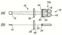
도 3을 참조하면, 레이저 빔을 증폭하기 위한 장치를 도시하며, 결정(14)으로 이루어진, 증폭 매체를 통해 레이저 빔(12)을 증폭하기 위한 레이저 증폭기가 일반적인 참고 부호(10)로 표시되어 있으며, 여기서 상기 결정(14)은 본 발명의 일 실시 예에 따라서, 펌프 모듈(16)에 의해서 펌핑된다. 도 3은 두 부분으로 이루어지며, 도 3(a)는 평면도이고, 도 3(b)는 측면도이다.Referring to FIG. 3, there is shown an apparatus for amplifying a laser beam, wherein a laser amplifier for amplifying the
결정(14)은 당 업계에 잘 알려진 바와 같이, 도핑될 수 있는 단일 결정 구조로 형성된 고체상 매체이다. 상기 결정(14)은 직사각형 단면을 갖는 것으로서, 짧은 모서리(26) 및 긴 모서리(28)를 제공한다. 이것은 단일 결정 슬래브로 지칭될 수도 있다. 결정이 설명되어 있지만, 상기 증폭 매체는 유리 또는 세라믹 일 수 있다. 또한, 상기 슬래브는 두 개의 도핑되지 않은 매체 사이에 도핑된 매체를 갖는 샌드위치 구조로 형성될 수 있다.
상기 레이저 빔(12)은, 전형적으로 마스터 발진기로서 간주되는 레이저 소스로부터 생성된다. 저 파워 레이저 마스터 발진기는, 레이저 증폭기(10) 내로 결합되는 펄스의 레이저 빔을 생성한다. 각각의 입력 펄스는 상기 결정(14) 내의 방출을 자극하고, 이는 입력 펄스에 추가되어 고출력 에너지 펄스를 생성한다. 이러한 방식으로, 상기 레이저 증폭기(10)는 파워 증폭기로 간주될 수 있고, 상기 레이저 빔은 시드 빔으로서 간주될 수 있다.The
결정(14)이 레이저 매체로서 작용하도록 하기 위하여, 그것은 보조 소스로부터 펌핑 될 필요가 있다. 이미터들의 선형 배열이 보조 소스를 제공한다. 본 실시 예에서, 상기 보조 소스는 다이오드 레이저, 또는 더욱 바람직하게는 레이저 다이오드 바(18)이다. 상기 레이저 다이오드 바(18)는 x-축을 따라 배치되고, y-축 내에서 단일 행 높이를 갖는 반도체 레이저 다이오드 이미터(20)의 선형 배열이며, 각각의 이미터(20)가 z-축에서 소스 빔(22)을 출력하도록 지향되어 있다. 상기 이미터(20)들은 바람직하게는 다중 모드 레이저 이미터들이다. 도면상에서, 가장 바깥 쪽의 다이오드 이미터들로부터의 빔만이 명확화를 위해서 표시되어 있다. 상기 x, y, z 축들은 표준 직각 좌표 시스템을 정의하며, 각각의 축은 다른 것들에 대해 직교한다. 상기 y-축은 빠른 축이라고 지칭하며, 도 3(b)에 도시되어 있다. 상기 빠른 축은 전형적으로, 반도체 웨이퍼에 수직인 수직축이다. 상기 빠른 축에서, 각각의 이미터는 빠르게 발산하는 가우스-형 모드를 생성한다. 느린 축에서, x-축은, 도 3(a)에 도시된 바와 같이, 바(18)에 평행하며, 각각의 이미터(20)로부터의 방출은 느린 발산을 갖는 모자(top hat)의 근사치를 제공하도록 조합된다. 따라서, 상기 소스 빔(22)들은 복합 펌프 빔을 제공하도록 조합되며, 이는 상기 결정(14)의 제1 면(24) 내로 결상된다.In order for the
상기 결정(14) 내로 상기 빔(22)들을 결상시키기 위하여, 상기 광학 조립체(30)가 상기 이미터(20)와, 상기 결정(14)의 직사각형의 측면 또는 제1 면(24) 사이에 위치된다. 도 3의 실시 예에서는, 레이저 다이오드 바(18) 내에 19개의 이미터(20) 들이 있다. 상기 광학 조립체(30)는 제1 렌즈(34), 제2 렌즈(40)의 배열 및 제3 렌즈(36)를 포함한다. 상기 광학 조립체(30)는 빠른 및 느린 축 내에서 독립적으로 간주될 수 있다.In order to image the
도 3(a)를 참조하면, 느린 축 내에서, 상기 광학 조립체(30)는 제2 렌즈(40)의 배열 및 제3 렌즈(36)를 도시한다. 상기 제2 렌즈(40)들은 초점 길이 f1x 를 갖는 느린 축 시준 렌즈(42)들의 배열이며, 이는 각각의 이미터(20) 이후에, f1x에 해당하는 거리 만큼 떨어져서 배치된다. 각각의 개별적인 렌즈(42)들은, 전형적으로 원통형 렌즈이며, 이는 하나의 이미터 소스 빔(22)에 작용한다.Referring to Figure 3 (a), within the slow axis, the
제3 렌즈(36)는 제2 렌즈(40)로부터 거리 L1 만큼 이격되어 있다. 상기 거리 L1는 핵심적인 사항은 아니지만, 설계 중에 다른 파라미터에 맞게 변화될 수 있다. 실제로, L1은 예를 들면, 도 7을 참조하면, 조립체 내에 다른 광학 구성 요소들을 위치시키도록 충분하게 크게 이루어질 수 있다. L1에 대한 전형적인 거리는 ~ 25mm이다. 제3 렌즈(36) 및 제1 면(24) 사이의 거리는 펌프 투사 거리이고, 제3 렌즈의 초점 길이 f2로서 선택된다. 상기 렌즈(36,40)들은 확대 배율,
제2 렌즈(40)의 원통형 렌즈 배열의 초점 길이 f1x은 이러한 배율을 제공하도록 선택된다. 빠른 축 시준이 포함되는 경우, 상기 조건은 또한, 제2 렌즈(40)가 상기 이미터(20)로부터 f1x 보다 다소 큰 물리적 거리에 위치되도록 하여 상기 빠른 축 렌즈(34)에 의해서 도입되는 느린 축의 굴절률을 보상하도록 요구된다. 제2및 제3 렌즈들의 광학 조립체(30) 조합은 2개-렌즈의 망원 확대기(38)로서 간주될 수 있다. 그러한 확대기(38)는 상당한 광학 파워, 예를 들면 x70를 가질 수 있고 면의 크기와 기하학적 형상의 범위에 맞도록 적응될 수 있다.The focal length f1x of the cylindrical lens array of the
따라서, 상기 렌즈(36,40)들의 초점 길이는, 각각의 소스 빔(22) 내에서 적절한 확장을 제공하도록 선택됨으로써, 그것들은 결정(14)을 중첩하고, 느린 축 내의 어떤 영역도 펌핑되지 않은 상태로 남아 있지 않도록 한다. 전형적으로, 상기 이미터(20)의 폭은 ~150㎛ 이고, 그리고 결정 길이는 ~ 7mm이며, 전형적으로 f1x = 1.8mm 및 f2 = 80mm로서 얻어지는 ~ 47의 확대를 필요로 한다. 중요한 것은, 상기 이미터들의 확대된 이미지들은, 제3 렌즈(36)에 대한 초점 길이에 형성되어 공간적인 중첩을 보장한다. 따라서, 상기 결정 주변의 빔의 누출이 최소화되고, 상기 이미터 출력에서의 어떠한 공간적 변화도 확대된 이미지에 걸쳐서 평균화되어 상기 결정(14)의 균일한 펌핑을 얻게 된다.Thus, the focal lengths of the
상기 빔들을 중첩시키는 데에 있어서, 상기 렌즈(36,40)들은 전형적으로, 거리 L1가 합계(f1x + f2)보다 작도록 선택되어, 결정(14) 내로 통과하는 소스 빔(22)들이 느린 축 내에서 발산 특성을 갖도록 하고, 이는 일정 각도에서 상기 결정(14)으로 진입하는 주변 소스 빔들의 내부 전반사로부터의 추가적인 효과로서, 전체 결정(14)이 실질적으로 균일하게 펌핑되는 것을 보장할 수 있도록 작용한다.In superimposing the beams, the
이러한 중복은 또한, 개별적인 레이저 다이오드 또는 레이저 다이오드 이미터(20)들의 일부 고장에 대한 면제를 제공한다. 하나의 이미터의 고장은 펌핑 파워를 줄일 수 있지만, 느린 축을 따른 어떤 지역도 펌핑되지 않은 상태로 남겨지지 않도록 한다. 이것은 개개의 레이저 다이오드 또는 레이저 다이오드 이미터의 고장이 펌핑되지 않은 영역을 초래하는 종래 기술과는 다른 것이다. 4 레벨의 레이저 결정에서, 이것은 원치 않는 열 효과를 발생시킬 수 있다. 또한, 준-3-레벨의 레이저 시스템에서, 펌핑되지 않은 영역은 흡수하고, 손실을 초래하며, 장치의 효율을 저하시킨다.This redundancy also provides an exemption for some failures of individual laser diodes or
빠른 축 내의 광학 조립체(30)를 고려하여, 도 3(b)를 참조하기로 한다. 상기 이미터(20)들을 나가는 소스 빔(22)들은 높은 차이를 갖는다. 따라서, 제1 렌즈(34)는 당 업계에서 잘 알려진 바와 같이 빠른 축 시준기이고, 발산을 느리게 한다. 전형적으로, 상기 빠른 축 시준은 0.6mm 내지 0.9mm 사이의 초점 길이 f1y를 갖는다. 상기 빠른 축 시준기(34)는 상기 이미터(20)로부터, 초점 길이 f1y에 위치되어 각각의 이미터 소스 빔(22)들은 광학 조립체(30)의 제1 렌즈(34)로 직접 진입한다.결과적으로 시준된 빠른 축 빔들은, 일반적으로 가우시안 빔에 양호한 근사치이며, 상기 초점 길이 f1y은 시준기, 렌즈(34)를 빠져나가는 때에, 2w0의 원하는 빔 높이를 제공하도록 선택된다. 표준 ABCD 행렬이 상기 광학 축을 따른 지점들에서, 빔 크기를 계산하는 데 사용되는 광학 배열과 ABCD 법칙을 기술하는 데 사용될 수 있다. 수차가 있을 수 있기 때문에, 당업자에게 공지되어 있는 바와 같이, 상기 제1 렌즈(34) 이후의 빔은, M2의 적절한 값, 전형적으로 1.3이 할당된다.With reference to the
상기 빠른 축 내의 광학 조립체는 제3 렌즈(36)를 포함한다. 이것은 구면 렌즈이고, 그것의 초점 길이(f2) 및 위치는 느린 축 내에서의 그것들의 요구 사항에 의해서 제어된다.The optical assembly within the fast axis includes a
결정(14) 내에서 얇은 이득 시트를 만들고자 하는 목적을 상기하면, 제1 면에서 원하는 빔 높이 2w1가 선택된다. 상기 빔 높이 2w1는 2w0보다 일반적으로 적다. 또한, 제1 면(24)에서 또는 근방에서 가우시안 허리가 있는 것이 바람직하며, 즉 상기 제3 렌즈 및 상기 빔 허리 사이의 허리 거리 L2는, f2로서 선택되었던 펌프 투사 거리와 같아야 한다.Recalling the purpose of making a thin gain sheet in the
빔 허리 위치 및 그 크기의 필요한 제어를 얻기 위해서는, ABCD 계산 프로세스는 미리 선택된 f2와 조합하여, 실질적인 한계 내에서 변화될 수 있는 파라미터들 W0 및 L1을 사용한다. 조합된 연산은 가장 적절한 디자인을 얻기 위해서 반복적인 해결책을 제공한다.In order to obtain the necessary control of the beam waist position and its size, the ABCD calculation process uses parameters W0 and L1 that can be varied within practical limits, in combination with preselected f2. The combined operations provide an iterative solution to obtain the most appropriate design.
상기 빔 허리 크기나 위치가 만족스럽지 않은 경우에는, 빠른 축 내에서 추가적인 원통형 포커싱 파워가 필요할 수 있다. 별도의 광학 부품을 도입하지 않고, 이를 얻는 하나의 방법은, 이미터(20)들에 대한 제1 렌즈(34)의 위치 조정에 의해서 이다. 이것은 양 또는 음의 파면 곡률 반경을 도입할 수 있어서, 수정된 ABCD 계산 내에 여분의 자유도를 제공한다.If the beam waist size or position is not satisfactory, additional cylindrical focusing power within the fast axis may be required. Without introducing a separate optical component, one way of obtaining this is by adjusting the position of the
상기 설명된 실시 예에서, 제3 렌즈(36)는 전형적으로 ~ 80mm의 초점 길이(f2)를 가지며, 빠른 축 시준기, 제1 렌즈(34)로부터 ~25mm에 배치된다. 상기 결정(14)은 제3 렌즈(36)로부터 f2의 거리에 위치된다. 따라서, ~1㎛ 반경의 이미터 소스 빔(22)은, 상기 결정(14)의 제1 면(24)에서 형성되는 ~100㎛의 펌핑된 스트라이프 절반 높이를 제공할 것이다. 상기 펌핑된 영역은 상기 결정(14)의 제1 면(24)의 영역이다. 상기 짧은 모서리(26) 상의 결정 높이는 0.75mm 내지 1mm 사이의 전형적인 값을 갖는다. 상기 펌핑된 영역의 면적의 높이는, 짧은 모서리(26) 상에서 총 결정 높이의 20% 내지 30%이어서, 얇은 이득 시트를 제공한다.In the embodiment described above, the
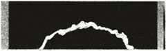
도 1의 종래 기술과는 달리, 근접-장(near-field)의 높은 종횡비의 빔이 전형적인 종횡비 > 10:1을 갖고, 결정(14) 상에 생성된다. 그것은 펌핑된 결정의 얇은 슬래브 또는 평면 도파관 구조의 기하학적 형상과 일치하기 때문에, 이것은 중요하다. 도 4는 상기에서 설명된 광학 조립체(30)를 사용하는 효과를 보여준다. 도 4(a)를 참조하면, 결상없이 상기 펌프 빔 프로파일은 서서히 중심으로부터 모서리쪽으로 향해 감소한다. 실제로, 직사각형 레이저 결정에 이러한 프로파일을 일치시키는 것은, 펌핑되지 않은 또는 적게 펌핑된 영역을 초래하여, 결정의 모서리들을 향하는 흡수 영역, 또는 결정의 모서리들을 넘어서 펌프 파워의 상당한 누출을 초래할 것이다. 이러한 경우는 모두, 비효율적인 장치를 초래할 것이다. 그러나, 개별적인 이미터 소스 빔들을 결상시키고, 그것들을 공간적으로 겹침으로써, 상기 펌프 빔 프로파일은 훨씬 더 선명한 모서리들을 갖는다. 이는 도 4(b)에 도시되어 있다. 이것은 상기 펌프 빔 프로파일 및 레이저 결정 사이에서 훨씬 가까운 일치를 허용하여 펌프 파워의 손실을 최소화하면서 레이저 결정의 효율적이고, 거의 균일한 펌핑을 얻게 된다.Unlike the prior art of FIG. 1, near-field high aspect ratio beams have a typical aspect ratio > 10: 1 and are created on the
단일 레이저 다이오드 바(18)를 사용하는, 펌프 모듈(16)을 포함한 레이저 증폭기(10a)의 다른 실시 예가, 도 5에 도시되어 있다. 명확화를 돕기 위해서, 도 3의 레이저 증폭기들에 유사한 부분에는 동일한 참조 번호가 부여되어 있으며, 빠른 축과 느린 축의 도시가 제공되어 있다.Another embodiment of a
도 5에서, 상기 레이저 다이오드 바(18)의 마운트(43)가 레이저 증폭기(10a) 내에서 레이저 다이오드 바(18)에 필요한 공간을 나타내기 위해서 도시되어 있다. 이러한 실시 예에서, 상기 빠르고, 느린 축의 시준기(34,40)들은, 상기 이미터(20)의 출력 소스 빔(22)에서, 상기 이미터(20)들의 전방에 장착된 하나의 광학 소자(44)로서 제공되어 있다. 상기 제3 렌즈(36)는 평면-볼록 구조이다. 따라서, 상기 느린 축 시준기(40)는 볼록 면(46) 상의 원하는 위치로 각각의 이미터 소스 빔(22)들을 지향시키도록 개별적으로 정렬되어, 상기 결정(14)의 펌핑 영역의 면적으로 결상된다.In Fig. 5, the
상기 결정(14)에 대한 입력 펌프 파워, 따라서 증폭기(10,10a) 내의 가능한 이득은, 다이오드 바(18) 당 사용 가능한 파워에 의해서 제한된다. 상기 파워의 크기를 조절하기 위해서, 추가적으로 다수의 다이오드 바(18)들이 단일의 펌프 모듈(16) 내에 결합될 수 있다. 거리 L1은 이것을 허용하기에 충분한 크기로 제조될 수 있으며, 각각의 레이저 다이오드 바(18)로부터의 각각의 소스 빔(22) 배열은 제3 렌즈(36)의 개구를 공유하게 된다.The input pump power for the
도 6은 나란하게 배치된 두 개의 바(18a,b)를 갖는 레이저 증폭기(10b)를 도시하며, 펌프 모듈(16)로부터의 잠재력을 두 배로 하고 있다. 상기 광학 조립체(30)에서, 각각의 바(18a,b)는 제1 렌즈로서 빠른 축 시준기(34a,b)를 가지며, 제2 렌즈로서 느린 축 시준기(40a,b)의 배열을 갖는다. 상기 이미터 소스 빔(22a,b)들은 제3 렌즈(36)의 작용에 의하여 결정(14)에서 느린 축에 중첩한다. 이러한 기술은 필요한 파워 크기조절을 생성하지만, 확대된 공간(footprint)을 갖는다.Figure 6 shows the
도 7을 참조하면, 레이저 증폭기(10c)가 도시되어 있으며, 이는 하나의 바 펌프 모듈의 설치 공간으로, 도 6의 두 개의 바 펌프 모듈(16)을 감소시키고자 하는 시도를 도시한다. 상기 다이오드 바(18a,b)들은 동일 평면상에 있지만, 하나의 다이오드 바(18b)는 제2의 다이오드 바(18a)에 대해 횡 방향으로 회전되어 있다. 거울(48)은 다이오드 바(18b) 상의 느린 축에 대해 45도로 위치되어 있어서, 횡 방향 이미터 소스 빔(22b)들을 제2 다이오드 바(18a)의 이미터 소스 빔(22a)으로 향해 평행한 경로를 따라 반사시킨다. 거울(48)은 마운트(43a)의 전면에 위치하지만, 이미터 소스 빔(22a)으로부터 벗어나 있다. 이것은 레이저 증폭기(10c)의 설치 면적을 줄이고, 제3 렌즈(36)의 필요한 직경도 감소시킨다.Referring to Fig. 7, a
이러한 시도는, 도 8 및 도 9에 도시된 바와 같이, 세 개, 네 개의 다이오드 바들로 확장될 수 있다. 도 8에 도시된 바와 같이, 상기 레이저 증폭기(10d)는 제3 다이오드 바(18c)를 구비하며, 이는 도 7의 배열의 제2 다이오드 바(18a)와는 횡으로 배치되고, 제1 다이오드 바(18b)에 대해서는 대향 위치된다. 제2 거울(48b)이 제3 다이오드 바(18c) 상의 느린 축에 대해 45도에 위치되어 횡 방향 이미터 소스 빔(22c)들을 제2 다이오드 바(18a)의 이미터 소스 빔(22a)으로 향해 평행한 경로를 따라서 반사시킨다. 거울(48b)은 마운트(43a)의 전면에 위치하지만, 이미터 소스 빔(22a)으로부터 벗어나 있다.Such an attempt can be extended to three or four diode bars, as shown in Figs. 8 and 9. 8, the laser amplifier 10d includes a
도 9에서, 레이저 증폭기(10e)는 도 7의 레이저 증폭기(10c)의 두 배로 간주될 수도 있으며, 여전히 광학 조립체(30) 내에 공통의 제3 렌즈(36)를 사용하고 있다. 상기 제3 렌즈(36)는 구형이며, 빠른 축과 느린 축 내에서 동일한 초점 길이를 제공하여 상기 결정(14)의 면(24) 상에 각각의 레이저 다이오드 바의 이미터들을 결상시킨다. 제4 레이저 다이오드 바(18d)는 도 6의 레이저 증폭기(10b)의 경우와 같이, 제2 레이저 다이오드 바(18a)에 대해 나란하게 배열되어 있다. 제1 다이오드 바(18a)는 제2 레이저 다이오드 바(18b)에 대해 횡방향으로 배치되고, 제3 레이저 다이오드 바(18c)는 제4 레이저 다이오드 바(18d)에 대해 횡방향으로 배치되며, 제2 레이저 다이오드 바(18b)와 제3 레이저 다이오드 바(18c)들은 서로 마주하고 있다. 제1 거울(48a)은 다이오드 바(18b) 상의 느린 축에 대해 45도에 위치되어 횡 방향 이미터 소스 빔(22b)들을 제2 다이오드 바(18a) 및 제4 다이오드 바(18d)의 이미터 소스 빔(22a,22b)들로 향해 평행한 경로를 따라서 반사시킨다. 제1 거울(48a)은 마운트(43a)의 전면에 위치하지만, 이미터 소스 빔(22a)으로부터 벗어나 있다. 제2 거울(48b)은 제3 다이오드 바(18c) 상의 느린 축에 대해 45도에 위치되어 횡 방향 이미터 소스 빔(22c)들을 제2 다이오드 바(18a) 및 제4 다이오드 바(18d)의 이미터 소스 빔(22a,22b)들로 향해 평행한 경로를 따라서 반사시킨다. 제2 거울(48b)은 제4 다이오드 바(18d)의 마운트(43a)의 전면에 위치하지만, 이미터 소스 빔(22d)으로부터 벗어나 있다.In Fig. 9, the
궁극적으로, 이 방식을 이용하여 크기를 조정하는 것은, 제3 렌즈(36)의 실제 개구에 의해서만 단지 제한된다. 2 개의 레이저 다이오드 바들이 서로 횡 방향으로 배치된 구조에서는, 보다 소형의 펌프 모듈(16)이 거울(48) 대신에 편광 조합 구조를 이용하여 가능하다. 도 10을 참조하면, 레이저 증폭기(10f)가 도시되어 있으며, 여기서는 광학 조립체(30)가 반 파장 판(50)을 사용하여 상기 횡방향 다이오드 바(18b)의 이미터 소스 빔(22b)의 편광을 제2 다이오드 바(18a)의 이미터 소스 빔(22a)에 비교하여 90도 만큼 회전시키고 있다. 편광 큐브(52)는 광학 소자(40a)및 제3 렌즈(36) 사이의 빔 경로 내에 위치된다. 제2 다이오드 바(18a)로부터의 이미터 소스 빔(22a)은 편광 큐브(52)를 통해 전송되지만, 상기 횡방향 다이오드 바(18b)의 이미터 소스 빔(22b)들은 이미터 소스 빔(22a)에 공동-선형으로 반사된다. 상기 편광 큐브(52) 이후의 이미터 소스 빔(22a,22b)들은 정확히 중첩되어 펌프 모듈(16)의 필요한 설치 공간과 제3 렌즈(36)의 개구를 줄인다. 이것은 다수의 다이오드 바들로 쉽게 확장될 수 있다.Ultimately, the size adjustment using this approach is limited only by the actual aperture of the
대안적으로, 상기 편광 큐브(52)는 색선별 거울에 의해서 대체되고, 상기 반 파장 판(50)은 제거된다. 다이오드 바(18a)는 색선별 거울을 통하여 높은 투과율을 갖는 제1 파장에서 동작한다. 다이오드 바(18b)는 색선별 거울로부터 높은 반사를 갖는 제2 파장에서 동작한다. 두 개의 다이오드 바(18a) 및 다이오드 바(18b)의 작동 파장들은 결정(14) 내에 높은 흡수를 가져서 효율적인 펌핑을 보장한다. 펌프 모듈(16)의 필요한 설치 면적 및 제3 렌즈(36)의 개구가 줄어든다. 이것은 다수의 다이오드 바들로 쉽게 확장될 수 있다.Alternatively, the
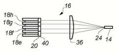
상기 레이저 증폭기(10a-f)들은 단일 평면 내에 배치된 레이저 다이오드 바들을 가지지만, 비-평면의 크기 조절 기술도 가능하다. 도 11을 참조하면, 서로에 대해 횡 방향으로 배치된 두 개의 레이저 다이오드 바(18a, 18b)들을 갖는 레이저 증폭기(10g)가 도시되어 있다. 하부의 빠른 축 측에서 볼 때, 횡방향 다이오드 바(18b)는 제2 레이저 다이오드 바(18a)의 약간 아래 또는 아래 평면에 위치한다. 거울(48a)은 다이오드 바(18b)의 느린 축에 대해 45도에 위치되어 횡 방향 이미터 소스 빔(22c)들을 제2 다이오드 바(18a)의 이미터 소스 빔(22a)들로 향해 실질적으로 평행한 경로를 따라서 반사시킨다. 상기 거울(48a)은 상기 횡방향 다이오드 바(18b)로부터의 이미터 소스 빔(22b)이 거울(48a)로부터 반사되도록 하지만, 제2 다이오드 바(18a)로부터의 이미터 소스 빔(22a)은 거울(48a)의 상부(54)를 스치듯 지나가게 하는 높이를 갖는다. 상기 제2 렌즈(36)의 역할은 빠른 축 내의 두 세트의 이미터 소스 빔(22a,22b)들을, 결정(14)에서 하나의 선으로 집중시키는 것이다. 레이저 다이오드 바(18e-h)들의 균일한 적층 배열이 사용될 수도 있다. 이것은 도 12에 도시되어 있다. 이미터(20)들의 2차원적 배열이 제공되어, 상기에서 설명된 실시 예들의 개별적인 다이오드 바(18e-h)들 내의 이미터 선형 배열 대신에 사용될 수 있다.The
도 3, 및 도 5 내지 도 12에는, 레이저 증폭기(10,10a-g)들에 펌프 모듈(16)이 제공되어 결정(14)의 하나의 면(24)에 펌프 빔을 제공하는 구조가 도시되어 있다. 바람직한 실시 예에서, 상기 레이저 빔(12)은 전파 축상의 결정(14)을 통하여 펌프 축(z-축)에 전파된다. 이것은 종래의 이노슬라브(INNOSLAB) 배열과는 다른 것이며, 바람직하게는 상기 결정(14)의 양측에서, 상기 펌프 빔과 레이저 빔을 분리하는 광학 소자, 전형적으로는 편광 큐브의 필요성을 제거한다.3 and 5 to 12 show a structure in which a
상기 펌프 빔은 결정에 진입한 후에, 비어 법칙에 따라서 흡수된다. 만일 이러한 흡수 공정이 신중하게 관리되지 않으면, 상기 결정 내의 지수적인 이득 및 온도 프로파일이 발생할 수 있다. 상기 결정은 증폭되거나 발진하는 레이저 빔(12)의 전달 축에 대해 횡 방향으로 펌핑되기 때문에, 심각한 빔 스티어링 또는 모달(madal) 왜곡이 발생할 수 있다. 이러한 효과를 완화시키기 위해서, 상기 빔은 양면으로 펌핑되고, 펌프 방향(z-축)에서의 결정의 불순물(dopant) 레벨 및 길이가 신중하게 선택된다. 양면 펌핑식 레이저 증폭기(10j)가, 도 13에 도시되어 있다. 제1 펌프 모듈(16a)은, 도 7을 참조하여 상기에서 설명한 바와 같이, 결정(14)의 제1 면(24) 상에 위치되어 있다. 제2 펌프 모듈(16b)은 결정(14)의 대향 측(56)에 위치되어 있다. 상기 펌프 모듈(16a,b)들의 레이저 다이오드 바(18)들은, 그것들의 이미터 소스 빔(22)들이 각각, 상기 결정(14)에서 동일 평면 내에 있는 펌프 빔(58a,b)을 형성하도록 배열되고, 그리고 상기 각각의 펌프 빔(58a,b)들은 그 각각의 광학 조립체(30a,b)를 통과한 후에, 상기 결정 내부에 있는 얇은 스트라이프 내로 중첩한다. 상기 제1 및 제2 펌프 모듈(16a,b)들은, 상기 결정의 양측(24,56)에서 동일한 펌프 파워와 펌프 빔 프로파일을 제공하도록 동일하다. 상기 펌프 모듈(16a,b)은, 도 7에 도시된 레이저 증폭기(10c)의 것들이지만, 본 발명의 임의의 실시 형태의 펌프 모듈이 사용될 수도 있다. 양면 펌핑에 의해서, 두 개의 펌프 프로파일들이 이질적으로 부가되어 지수적 붕괴의 효과를 감소시킨다. 추가적인 감소가 상기 결정 매체의 흡수를 최적화함으로써, 적절한 레이저 효율을 보장하는 것이 가능하며, 상기 펌프 빔의 ~ 70% 내지 80%가 각각의 펌프 모듈(16a,b)로부터 흡수된다.After entering the crystal, the pump beam is absorbed in accordance with the Via law. If this absorption process is not carefully managed, then exponential gain and temperature profiles within the crystal can occur. Since the crystal is pumped transversely to the axis of propagation of the amplified or
양면 펌핑 장치의 또 다른 실시 예 구성이 도 14에 도시되어 있다. 도 13의 구성의 유사한 부분에는 그 명확성을 돕기 위해서 동일한 참조 번호가 부여되어 있다. 펌프 모듈(16b)의 빔 전파 축은, 이제 레이저 결정 펌프 축에 대해 α의 각도에서 기울어져 있다. 바람직하게는, 각도 α는 0도 내지 20도의 범위이다. 펌프 모듈(16a)의 빔 축은, 레이저 결정 펌프 축과 동일 선상에 있다. 상기 펌프 모듈(16a,b)의 상대적인 경사는, 상기 펌프 빔들이 상기 펌프 모듈 이미터 면들을 타격하고, 조기 파손을 일으키는 것을 방지하며, 균일 펌핑이 유지되도록 한다. 추가적인 실시 예에서, 펌프 모듈(16a)의 빔 전파 축도 상기 레이저 결정 펌프 축에 대하여 경사질 수 있다.Another embodiment of the double-sided pumping device is shown in Fig. Similar parts of the configuration of Fig. 13 are assigned the same reference numerals to facilitate clarity. The beam propagation axis of the
상기 레이저 다이오드 바는 광학 조립체에 의해서 결정으로부터 물리적으로 분리되어 있기 때문에, 이것은 상기 펌프 면들로 일정 각도에서 상기 결정의 펌핑을 허용한다. 이것은, 양면 펌핑 시에, 임의의 흡수되지 않은 힘이 양측 상에서, 상기 레이저 다이오드 면들로부터 공간적으로 분리될 수 있기 때문에, 특히 유용하다. 만일 상기 레이저 다이오드의 출력들이 격리되지 않는 경우, 상기 이미터들의 신뢰성은 수명에 관련되어 단축될 수 있다.Because the laser diode bar is physically separated from the crystal by the optical assembly, it allows pumping of the crystal at a certain angle to the pump faces. This is particularly useful because, during double-sided pumping, any unabsorbed force can be spatially separated from the laser diode surfaces on both sides. If the outputs of the laser diode are not isolated, the reliability of the emitters can be shortened in relation to lifetime.
상기 펌프 모듈(16a,b)들을 경사시키는 것에 대한 대안으로서, 상기 펌프 빔은 y 방향으로 작은 변위를 제공하도록 지향될 수 있다. 제3 렌즈를 통한 빠른 축 빔의 통과는 상기 빔을 지향시키는 수단을 제공한다.As an alternative to tilting the
또한, 상기 결정(14)은, 그것이 증폭기로서 사용되는 때에, 원하지 않는 내부 레이저 발진을 방지하기 위해서 약하게 경사진 면(24,56)들을 갖는 것이 유리할 수도 있다.The
도 14의 구성을 사용하여 양면이 펌핑될 때, 상기 레이저 결정으로부터 얻어진 형광을 분석함으로써, 상기 결정의 중심 펌핑 영역은 x-축을 따라서, 그리고 y-축을 따른 가우시안 근방에서 고도로 균일하게 된다. 도 15는 증폭된 빔의 전파 방향에 대한 소 신호 이득 계수 측정값(62)의 그래프를 도시하며, 이는 정규화된 슬래브 위치(64), 즉 세 가지 다른 펌프의 구성에 대하여 중심으로부터의 거리를 슬래브 폭으로 나누어서 표시되어 있다. 포인트(66)들은 하나의 모듈로부터의 펌핑을 나타내고, 그리고 단지 하나의 모듈로서 상기 결정을 펌핑하여, 소 신호 이득 계수는 비어 법칙으로부터 예상되는 바와 같이, 상기 결정의 입력 펌프 모서리로부터 감소하면서 멀어지는 것을 도시한다. 포인트(68)도 단일 모듈로부터의 펌핑을 나타내지만, 상기 결정의 반대 측에 위치된 것으로서, 소 신호 이득 계수는 상기 결정의 입력 펌프 모서리로부터 감소하면서 멀어지는 것을 다시 도시한다. 이것은 빔 스티어링, 열 응력 및 낮은 펌프 파워에서 흡수될 수 있는 낮은 퍼퓰레이션(population) 반전 영역에 의존되는 펌프를 생성할 것이다. 상기 그래프 상의 포인트(70)들은 두 개의 펌프 모듈들이 작동하고, 상기 결정이 양면으로 펌핑되는 경우를 나타낸다. 포인트(70)들은 상기 형광 프로파일로부터 예상되는 바와 같이, 상기 소 신호 이득 계수가 레이저 결정의 폭을 가로질러서 거의 불변인 상태를 도시한다. 이러한 높은 균일성은 최소한의 열 효과와 균일한 반전을 보장한다.By analyzing the fluorescence obtained from the laser crystal when both sides are pumped using the configuration of FIG. 14, the central pumping region of the crystal becomes highly uniform along the x-axis and near the Gaussian along the y-axis. Figure 15 shows a graph of the small signal
여기에서 기재된 레이저 증폭기는 단일 통과용 레이저 빔에 사용될 수 있다. 대안적으로, 상기 레이저 빔은, 본 출원인에게 허여된 GB2505315호에 기재된 전치- 및 파워 증폭기와 같은 다중-통과 증폭기 내에 배치될 수 있다. GB2505315호는 여기에서 참조로 인용되어 있으며, 최적의 파워 레벨들로 저파워 초단 펄스의 증폭을 가능하게 하도록 하나의 직사각형 활성 매체 내에서 전치 증폭기 및 파워 증폭기를 통합시키는 광학 증폭기를 설명한다. 레이저 빔은 매체의 다수의 횡단을 이루는 제1 전치-증폭 경로를 따라서 상기 증폭 매체를 통과한다. 그것은 전치-증폭기로서, 상기 매체의 이중 통과를 이루기 위해서 제1 경로를 따라서 후방으로 결상된다. 상기 빔은 그 다음, 단일 통과 내에 상기 매체의 다중 횡단을 이루도록, 제2 파워 증폭 경로 상에서 다시 매체 내로 재-결상된다. 상기 경로들은 독립적이지만, 중첩되어 효율적인 파워 추출이 달성된다. 본 발명의 레이저 증폭기를 이용하면, 상기 하나의 직사각형 활성 매체는 여기에서 설명된 레이저 결정이며, 그 이미터들이 본 발명의 실시 예에 따라서, 상기 레이저 빔의 전파 방향에 대해 가로지르는 펌프 축들을 갖는 광학 조립체들을 통해서 상기 결정의 하나의 또는 대향의 표면들 상에 결상되는, 하나 또는 그 이상의 레이저 다이오드 바들을 포함하는 펌프 모듈들로부터 펌핑된다.The laser amplifier described herein can be used for a single pass laser beam. Alternatively, the laser beam may be placed in a multi-pass amplifier, such as a pre-and power amplifier as described in GB 2505315 to the Applicant. GB2505315, which is incorporated herein by reference, describes an optical amplifier that integrates a preamplifier and a power amplifier in one rectangular active medium to enable amplification of low power short pulses at optimal power levels. The laser beam passes through the amplification medium along a first pre-amplification path that comprises multiple traverses of the medium. It is a pre-amplifier and is imaged backwards along the first path to achieve a double pass of the medium. The beam is then re-imaged into the medium again over the second power amplification path to form multiple traverses of the medium in a single pass. The paths are independent, but superimposed to achieve efficient power extraction. Using the laser amplifier of the present invention, the one rectangular active medium is a laser crystal as described herein, and the emitters are arranged according to an embodiment of the present invention, with pump axes transverse to the propagation direction of the laser beam Is pumped from pump modules that include one or more laser diode bars that are imaged on one or opposite surfaces of the crystal through optical assemblies.
본 발명의 원리적인 장점은, 간단한 광학 조립체를 통해서 증폭 매체를 채울 수 있는 크기의 소스 빔들을 중첩시키는 것이, MOPA 내의 결정과 같은 증폭 매체의 균질한 펌핑을 위해서, 근접-장, 높은 종횡비의 펌프 빔을 제공하는 레이저 빔 증폭장치 및 방법을 제공하는 것이다It is a principle advantage of the present invention that superimposing source beams of a size that can fill the amplification medium through a simple optical assembly is advantageous for homogeneous pumping of amplification media, such as crystals in MOPA, A laser beam amplifying apparatus and method for providing a beam
본 발명의 적어도 일 실시 예의 또 다른 장점은, 동일한 광학 시스템을 통해서 다수의 이미터들을 간단히 결합시킴으로써, 파워 크기의 조정이 이루어질 수 있는 레이저 빔 증폭장치 및 방법을 제공하는 것이다.It is a further advantage of at least one embodiment of the present invention to provide a laser beam amplifying apparatus and method by which power magnitude adjustment can be made by simply coupling a plurality of emitters through the same optical system.
본 발명의 적어도 일 실시 예의 또 다른 장점은, 고장난 이미터가 증폭 매체의 펌핑되지 않는 영역을 발생시키지 않는 중복성을 제공하는 레이저 빔 증폭장치 및 방법을 제공한다는 점이며, 상기 장치는 보수 성능이 우수하여 모두 쉽게 교체될 수 있는 몇몇 구성 요소들을 갖는다.Yet another advantage of at least one embodiment of the present invention is that it provides a laser beam amplifying apparatus and method that provides redundancy in which a failed emitter does not generate an un-pumped region of the amplification medium, Have some components that can all be easily replaced.
본 발명의 적어도 일 실시 예의 또 다른 장점은, 종래 기술보다 더욱 간단하고 소형의 구성으로서, 이중 펌핑식의 광학적으로 여기된 단일 결정상 슬래브 활성 영역을 갖는 레이저 증폭기를 제공하는 레이저 빔 증폭 장치 및 방법을 제공하는 것이다.Yet another advantage of at least one embodiment of the present invention is a laser beam amplifying apparatus and method for providing a laser amplifier having a dual pumping optically excited single crystal slab active region as a simpler and smaller construction than the prior art .
여러 가지 변형들이 본원 발명의 특허 청구 범위에 기재된 발명의 범위를 벗어나지 않고서, 여기에서 설명된 본 발명에 이루어질 수 있음은 당업자들에 의해서 이해될 수 있을 것이다. 예를 들면, 상기 파워 크기조절 기술이 광학 조립체를 이용하여 이루어질 수 있는 것으로 설명되어 있지만, 당업자들은 다른 구성이 가능하다는 것을 잘 인식할 수 있을 것이다. 제3 렌즈에 대해 하나의 렌즈가 도시되어 있지만, 그것은 한 쌍의 렌즈로 치환될 수 있음을 잘 이해할 수 있을 것이다. 증폭 매체의 면이 설명되어 있지만, 그러한 기술은 렌즈 쌍을 필요로 하는 도파로 내로 최적의 결합을 제공하기 위해서 적용될 수 있을 것이다.It will be understood by those skilled in the art that various modifications may be made to the invention described herein without departing from the scope of the invention as set forth in the claims of the invention. For example, although the power sizing technique is described as being able to be accomplished using optical assemblies, those skilled in the art will recognize that other configurations are possible. Although one lens is shown for the third lens, it will be appreciated that it can be replaced with a pair of lenses. Although the plane of the amplification medium is described, such a technique may be applied to provide optimal coupling into a waveguide requiring a lens pair.
10: 레이더 증폭기 12: 레이저 빔
14: 결정 16: 펌프 모듈
18: 레이저 다이오드 바 20: 이미터
22: 소스 빔 24: 제1 면
26: 짧은 모서리 28: 긴 모서리
30: 광학 조립체 34: 제1 렌즈
36: 제3 렌즈 38: 확대기
40: 제2 렌즈 42: 렌즈
44: 광학 소자 46: 볼록 면
48: 거울10: Radar amplifier 12: Laser beam
14: Decision 16: Pump module
18: laser diode bar 20: emitter
22: source beam 24: first side
26: Short edge 28: Long edge
30: optical assembly 34: first lens
36: Third lens 38: Magnifier
40: second lens 42: lens
44: optical element 46: convex surface
48: Mirror
Claims (25)
Translated fromKorean그리고 펌프 모듈을 포함하며, 상기 펌프 모듈은:
펌프 빔, 상기 펌프 빔은 x-축에 평행한 느린 축과, y-축에 평행한 빠른 축을 갖는 선형 배열 내에 배치된 이미터들로부터의 소스 빔들의 합성물이고;
그리고 상기 이미터들 및 상기 증폭 매체의 제1 면 사이에 위치된 광학 조립체;를 포함하며,
상기 광학 조립체는:
상기 이미터들에 인접하여, 상기 펌프 빔 상에 작용하도록 구성된 빠른 축 내의 제1 렌즈, 및 상기 느린 축 내의 제2 렌즈 배열을 포함하고, 각각의 제2 렌즈는 개별적인 소스 빔에 작용하도록 구성되고, 그리고 상기 제1 및 제2 렌즈로부터 일정 간격 떨어져서, 상기 펌프 빔에 작용하도록 구성된 제3 렌즈를 포함하며;
여기서, 상기 개별적인 소스 빔들은 제1 면에서 중첩되고, 상기 느린 축 내의 긴 모서리를 따라서 제1 면을 채우도록 결상되고, 크기가 조절되며, 상기 빠른 축 내에서 상기 짧은 모서리의 길이보다 작은 빔 크기로 포커싱되고;
그에 따라서, 상기 증폭 매체의 균질한 펌핑을 제공하며, 상기 펌프 빔에 직교하는 방향에서 상기 증폭 매체를 통과한 레이저 빔은 균일하게 증폭되는 것을 포함하는 레이저 빔 증폭장치.An amplification medium having a rectangular cross section providing a first face having a long edge and a short edge, the long edge being along the x-axis, the short edge along the y-axis, and the z-axis forming the pump axis within the rectangular coordinate system ;
And a pump module, the pump module comprising:
Pump beam, the pump beam is a composite of source beams from emitters arranged in a linear array having a slow axis parallel to the x-axis and a fast axis parallel to the y-axis;
And an optical assembly positioned between the emitters and the first surface of the amplification medium,
The optical assembly comprising:
A first lens in the fast axis configured to act on the pump beam adjacent to the emitters and a second lens array in the slow axis, each second lens configured to act on a respective source beam, And a third lens configured to act on the pump beam at a distance from the first and second lenses;
Wherein the individual source beams are superimposed on a first surface and are sized and sized to fill a first surface along a long edge in the slow axis, wherein a beam size smaller than the length of the short edge in the fast axis / RTI >
Thereby providing homogeneous pumping of the amplification medium, wherein the laser beam passing through the amplification medium in a direction orthogonal to the pump beam is uniformly amplified.
b) 상기 이미터들과 상기 증폭 매체의 제1 면 사이에 광학 조립체를 제공하는 단계, 상기 광학 조립체는, 상기 소스 빔에 작용하기 위하여 상기 이미터들에 인접한 빠른 축 내의 제1 렌즈; 느린 축 내에서, 상기 제1 렌즈에 인접한 제2 렌즈들의 배열, 각각의 제2 렌즈들은 개별적인 소스 빔 상에 작용하도록 구성됨; 및 상기 제1 및 제2 렌즈로부터 일정 간격 떨어지고, 소스 빔 상에 작용하도록 구성된 제3 렌즈를 포함함; 그리고
c) 상기 증폭 매체의 제1 면 상에 개별적인 소스 빔들을 중첩시키도록 상기 렌즈들을 이격시키는 단계; 상기 개별적인 소스 빔들은 느린 축 내에서 상기 증폭 매체의 긴 모서리를 따라서 제1 면을 채우도록 결상되고, 그리고 크기가 조절됨; 상기 개별적인 소스 빔들은 빠른 축 내에서 상기 증폭 매체의 짧은 모서리의 길이보다 작은 빔 크기로 포커싱되며; 그리고 주변의 소스 빔들은 상기 증폭 매체로의 유입시 내부 전반사를 겪는 단계;들을 포함하는 증폭 매체를 통한 균질한 복합 빔 펌핑 방법.a) providing a plurality of source beams from emitters arranged in a linear array;
b) providing an optical assembly between the emitters and a first side of the amplification medium, the optical assembly comprising: a first lens in a fast axis adjacent the emitters to act on the source beam; Within the slow axis, an array of second lenses adjacent to the first lens, each second lens configured to act on an individual source beam; And a third lens spaced apart from the first and second lenses and configured to act on the source beam; And
c) spacing the lenses to overlap the individual source beams on the first side of the amplification medium; The individual source beams are imaged and sized to fill a first side along a long edge of the amplification medium in a slow axis; The individual source beams being focused in a fast axis to a beam size smaller than the length of the short edge of the amplification medium; And surrounding source beams undergo total internal reflection upon entry into the amplification medium. ≪ Desc / Clms Page number 13 >
24. The method according to claim 22 or 23, wherein the individual source beams have a beam waist and the position of the first lens relative to the emitters is adjusted to vary the position of the beam waist relative to the first face Lt; / RTI >
Applications Claiming Priority (2)
| Application Number | Priority Date | Filing Date | Title |
|---|---|---|---|
| GB1501171.1 | 2015-01-23 | ||
| GB1501171.1AGB2518794B (en) | 2015-01-23 | 2015-01-23 | Laser beam amplification by homogenous pumping of an amplification medium |
Publications (2)
| Publication Number | Publication Date |
|---|---|
| KR20160091243Atrue KR20160091243A (en) | 2016-08-02 |
| KR101702246B1 KR101702246B1 (en) | 2017-02-02 |
Family
ID=52623084
Family Applications (1)
| Application Number | Title | Priority Date | Filing Date |
|---|---|---|---|
| KR1020150188128AActiveKR101702246B1 (en) | 2015-01-23 | 2015-12-29 | Laser beam amplification by homogenous pumping of an amplification medium |
Country Status (9)
| Country | Link |
|---|---|
| US (1) | US9847616B1 (en) |
| EP (1) | EP3048678B1 (en) |
| JP (1) | JP5994033B2 (en) |
| KR (1) | KR101702246B1 (en) |
| CN (1) | CN105826806B (en) |
| ES (1) | ES2672047T3 (en) |
| GB (1) | GB2518794B (en) |
| LT (1) | LT3048678T (en) |
| TW (1) | TWI575828B (en) |
Cited By (1)
| Publication number | Priority date | Publication date | Assignee | Title |
|---|---|---|---|---|
| WO2019083253A1 (en)* | 2017-10-25 | 2019-05-02 | 주식회사 루트로닉 | Laser device for treatment |
Families Citing this family (12)
| Publication number | Priority date | Publication date | Assignee | Title |
|---|---|---|---|---|
| WO2017205842A1 (en)* | 2016-05-26 | 2017-11-30 | Compound Photonics Ltd | Solid-state laser system |
| WO2018037663A1 (en)* | 2016-08-26 | 2018-03-01 | パナソニックIpマネジメント株式会社 | Laser module |
| US10066986B2 (en)* | 2016-08-31 | 2018-09-04 | GM Global Technology Operations LLC | Light emitting sensor having a plurality of secondary lenses of a moveable control structure for controlling the passage of light between a plurality of light emitters and a primary lens |
| DE102017002907A1 (en)* | 2017-03-27 | 2018-09-27 | Keming Du | Arrangements for amplifying multiple beams |
| DE102017115964B4 (en)* | 2017-07-14 | 2020-04-02 | LIMO GmbH | Device for generating a linear intensity distribution of laser radiation |
| US11231569B2 (en)* | 2018-06-13 | 2022-01-25 | Panasonic Corporation | Light-emitting device and illumination device |
| CN111468825B (en)* | 2019-01-24 | 2022-06-28 | 日亚化学工业株式会社 | Light source assembly |
| JP7041362B2 (en)* | 2019-01-24 | 2022-03-24 | 日亜化学工業株式会社 | Light source unit |
| CN112513706A (en)* | 2019-07-08 | 2021-03-16 | Limo显示有限责任公司 | Conversion device for laser radiation |
| CN111244742B (en)* | 2020-03-18 | 2021-05-04 | 中国工程物理研究院激光聚变研究中心 | Multi-channel homologous pumping system and control method thereof |
| JP7525780B2 (en)* | 2020-07-22 | 2024-07-31 | 日亜化学工業株式会社 | Light source unit |
| CN114247988B (en)* | 2020-09-23 | 2024-05-10 | 深圳市联赢激光股份有限公司 | Laser light source |
Citations (4)
| Publication number | Priority date | Publication date | Assignee | Title |
|---|---|---|---|---|
| US5541951A (en)* | 1994-11-14 | 1996-07-30 | Intelligent Surgical Lasers, Inc. | Device and method for high-power end pumping |
| JP2003008273A (en)* | 2001-06-25 | 2003-01-10 | Fanuc Ltd | Cooler and light source apparatus |
| US20060221439A1 (en)* | 2005-03-31 | 2006-10-05 | Michael Kuhnelt | Laser device |
| JP2014041909A (en)* | 2012-08-22 | 2014-03-06 | Sumitomo Heavy Ind Ltd | Laser irradiation device |
Family Cites Families (19)
| Publication number | Priority date | Publication date | Assignee | Title |
|---|---|---|---|---|
| US5139609A (en)* | 1991-02-11 | 1992-08-18 | The Aerospace Corporation | Apparatus and method for longitudinal diode bar pumping of solid state lasers |
| CA2072290A1 (en)* | 1991-08-27 | 1993-02-28 | Juan L. Julia | Forming leveling tool |
| WO1997029529A1 (en) | 1996-02-07 | 1997-08-14 | Fraunhofer-Gesellschaft zur Förderung der angewandten Forschung e.V. | Optically pumped intensifying agent, in particular a solid intensifying agent |
| US6124973A (en) | 1996-02-23 | 2000-09-26 | Fraunhofer Gesellschaft Zur Foerderung Der Angewandten Forschung E.V. | Device for providing the cross-section of the radiation emitted by several solid-state and/or semiconductor diode lasers with a specific geometry |
| US6671305B2 (en)* | 1996-11-29 | 2003-12-30 | Corporation For Laser Optics Research | Solid state laser |
| US7046711B2 (en) | 1999-06-11 | 2006-05-16 | High Q Laser Production Gmbh | High power and high gain saturation diode pumped laser means and diode array pumping device |
| DE10293001D2 (en)* | 2001-07-05 | 2004-08-05 | Hentze Lissotschenko Patentver | Arrangement for imaging the light emanating from a laser diode bar into a focal plane |
| US6738396B2 (en) | 2001-07-24 | 2004-05-18 | Gsi Lumonics Ltd. | Laser based material processing methods and scalable architecture for material processing |
| US6785304B2 (en) | 2001-07-24 | 2004-08-31 | Gsi Lumonics, Inc. | Waveguide device with mode control and pump light confinement and method of using same |
| US7065121B2 (en) | 2001-07-24 | 2006-06-20 | Gsi Group Ltd. | Waveguide architecture, waveguide devices for laser processing and beam control, and laser processing applications |
| US20030138021A1 (en) | 2001-10-25 | 2003-07-24 | Norman Hodgson | Diode-pumped solid-state thin slab laser |
| FR2849545B1 (en)* | 2002-12-31 | 2005-04-08 | Thales Sa | OPTICAL FIBER POWER SOURCE SOURCE WITH SINGLE PUMP SOURCE |
| JP2005107319A (en) | 2003-09-30 | 2005-04-21 | Toshiba Corp | Optical module, optical fiber laser device, video display device |
| JP2005158886A (en)* | 2003-11-21 | 2005-06-16 | Hamamatsu Photonics Kk | Optical amplifier, laser oscillator, and mopa laser device |
| US7881355B2 (en) | 2005-12-15 | 2011-02-01 | Mind Melters, Inc. | System and method for generating intense laser light from laser diode arrays |
| US7639722B1 (en)* | 2007-10-29 | 2009-12-29 | The United States Of America As Represented By The Secretary Of The Air Force | Multifaceted prism to cause the overlap of beams from a stack of diode laser bars |
| EP2184818A1 (en)* | 2008-11-10 | 2010-05-12 | High Q Technologies GmbH | Laser pump arrangement and laser pump method with beam homogenisation |
| US8596823B2 (en)* | 2010-09-07 | 2013-12-03 | Coherent, Inc. | Line-projection apparatus for arrays of diode-laser bar stacks |
| CN102593714B (en)* | 2012-02-28 | 2016-01-20 | 武汉光迅科技股份有限公司 | The semiconductor Raman pump laser of single pump multi-wavelength oscillation and pumping composite wave appts |
- 2015
- 2015-01-23GBGB1501171.1Apatent/GB2518794B/enactiveActive
- 2015-12-29KRKR1020150188128Apatent/KR101702246B1/enactiveActive
- 2016
- 2016-01-05TWTW105100191Apatent/TWI575828B/enactive
- 2016-01-18CNCN201610030895.2Apatent/CN105826806B/enactiveActive
- 2016-01-18USUS14/997,757patent/US9847616B1/enactiveActive
- 2016-01-20JPJP2016008982Apatent/JP5994033B2/enactiveActive
- 2016-01-22ESES16152376.6Tpatent/ES2672047T3/enactiveActive
- 2016-01-22LTLTEP16152376.6Tpatent/LT3048678T/enunknown
- 2016-01-22EPEP16152376.6Apatent/EP3048678B1/enactiveActive
Patent Citations (4)
| Publication number | Priority date | Publication date | Assignee | Title |
|---|---|---|---|---|
| US5541951A (en)* | 1994-11-14 | 1996-07-30 | Intelligent Surgical Lasers, Inc. | Device and method for high-power end pumping |
| JP2003008273A (en)* | 2001-06-25 | 2003-01-10 | Fanuc Ltd | Cooler and light source apparatus |
| US20060221439A1 (en)* | 2005-03-31 | 2006-10-05 | Michael Kuhnelt | Laser device |
| JP2014041909A (en)* | 2012-08-22 | 2014-03-06 | Sumitomo Heavy Ind Ltd | Laser irradiation device |
Cited By (2)
| Publication number | Priority date | Publication date | Assignee | Title |
|---|---|---|---|---|
| WO2019083253A1 (en)* | 2017-10-25 | 2019-05-02 | 주식회사 루트로닉 | Laser device for treatment |
| KR20190046223A (en)* | 2017-10-25 | 2019-05-07 | 주식회사 루트로닉 | Medical laser device |
Also Published As
| Publication number | Publication date |
|---|---|
| US20170346254A1 (en) | 2017-11-30 |
| GB2518794A (en) | 2015-04-01 |
| EP3048678A1 (en) | 2016-07-27 |
| TW201633639A (en) | 2016-09-16 |
| LT3048678T (en) | 2018-06-25 |
| ES2672047T3 (en) | 2018-06-12 |
| KR101702246B1 (en) | 2017-02-02 |
| GB201501171D0 (en) | 2015-03-11 |
| JP5994033B2 (en) | 2016-09-21 |
| CN105826806A (en) | 2016-08-03 |
| US9847616B1 (en) | 2017-12-19 |
| CN105826806B (en) | 2018-03-13 |
| JP2016136626A (en) | 2016-07-28 |
| EP3048678B1 (en) | 2018-05-09 |
| GB2518794B (en) | 2016-01-13 |
| TWI575828B (en) | 2017-03-21 |
Similar Documents
| Publication | Publication Date | Title |
|---|---|---|
| KR101702246B1 (en) | Laser beam amplification by homogenous pumping of an amplification medium | |
| JP3589299B2 (en) | Beam shaping device | |
| JP2010114162A (en) | Laser gain medium, laser oscillator, and laser amplifier | |
| JPH08250797A (en) | Solid-state laser device | |
| JP2009525592A (en) | Apparatus for longitudinal pumping of laser media | |
| US7480318B2 (en) | Side-pumped solid-state laser source, and pumping process for a solid-state laser source | |
| US9306366B2 (en) | Optical amplifier arrangement | |
| US5076678A (en) | Laser diode light imaging optics | |
| KR102520071B1 (en) | Polarized optical pumping and laser apparatus comprising the same | |
| CN110574244B (en) | Homogenization of pump laser radiation | |
| KR20230119143A (en) | A device for amplifying a laser beam | |
| Seyedzamani et al. | Simple highly efficient pumping configuration in high-power thin-disk laser | |
| KR20230119142A (en) | laser beam amplifying device | |
| JP2024537566A (en) | Thin-disk laser system with homogenized optical pump source | |
| JP3086090B2 (en) | Gas laser equipment | |
| US11387620B2 (en) | Compact Raman laser capable of efficient operation at low peak powers with good beam quality | |
| JP7584732B2 (en) | Laser Equipment | |
| JP2006203117A (en) | Solid state laser equipment | |
| JP2550693B2 (en) | Solid-state laser device | |
| CN119496025A (en) | A double-end LD pumped crystal rod amplifier module |
Legal Events
| Date | Code | Title | Description |
|---|---|---|---|
| PA0109 | Patent application | Patent event code:PA01091R01D Comment text:Patent Application Patent event date:20151229 | |
| A201 | Request for examination | ||
| A302 | Request for accelerated examination | ||
| PA0201 | Request for examination | Patent event code:PA02012R01D Patent event date:20160512 Comment text:Request for Examination of Application Patent event code:PA02011R01I Patent event date:20151229 Comment text:Patent Application | |
| PA0302 | Request for accelerated examination | Patent event date:20160512 Patent event code:PA03022R01D Comment text:Request for Accelerated Examination Patent event date:20151229 Patent event code:PA03021R01I Comment text:Patent Application | |
| E902 | Notification of reason for refusal | ||
| PE0902 | Notice of grounds for rejection | Comment text:Notification of reason for refusal Patent event date:20160621 Patent event code:PE09021S01D | |
| PG1501 | Laying open of application | ||
| E701 | Decision to grant or registration of patent right | ||
| PE0701 | Decision of registration | Patent event code:PE07011S01D Comment text:Decision to Grant Registration Patent event date:20161110 | |
| GRNT | Written decision to grant | ||
| PR0701 | Registration of establishment | Comment text:Registration of Establishment Patent event date:20170125 Patent event code:PR07011E01D | |
| PR1002 | Payment of registration fee | Payment date:20170125 End annual number:3 Start annual number:1 | |
| PG1601 | Publication of registration | ||
| FPAY | Annual fee payment | Payment date:20191226 Year of fee payment:4 | |
| PR1001 | Payment of annual fee | Payment date:20191226 Start annual number:4 End annual number:4 | |
| PR1001 | Payment of annual fee | Payment date:20210111 Start annual number:5 End annual number:5 | |
| PR1001 | Payment of annual fee | Payment date:20221123 Start annual number:7 End annual number:7 | |
| PR1001 | Payment of annual fee | Payment date:20231122 Start annual number:8 End annual number:8 | |
| PR1001 | Payment of annual fee | Payment date:20241106 Start annual number:9 End annual number:9 |