KR20160089219A - Oled light engine - Google Patents
Oled light engineDownload PDFInfo
- Publication number
- KR20160089219A KR20160089219AKR1020150008900AKR20150008900AKR20160089219AKR 20160089219 AKR20160089219 AKR 20160089219AKR 1020150008900 AKR1020150008900 AKR 1020150008900AKR 20150008900 AKR20150008900 AKR 20150008900AKR 20160089219 AKR20160089219 AKR 20160089219A
- Authority
- KR
- South Korea
- Prior art keywords
- housing
- oled lighting
- lighting panel
- adapter
- oled
- Prior art date
- Legal status (The legal status is an assumption and is not a legal conclusion. Google has not performed a legal analysis and makes no representation as to the accuracy of the status listed.)
- Ceased
Links
Images


Classifications
- H—ELECTRICITY
- H10—SEMICONDUCTOR DEVICES; ELECTRIC SOLID-STATE DEVICES NOT OTHERWISE PROVIDED FOR
- H10K—ORGANIC ELECTRIC SOLID-STATE DEVICES
- H10K71/00—Manufacture or treatment specially adapted for the organic devices covered by this subclass
- H01L51/56—
Landscapes
- Engineering & Computer Science (AREA)
- Manufacturing & Machinery (AREA)
- Electroluminescent Light Sources (AREA)
Abstract
Description
Translated fromKorean본 명세서는 OLED 조명 엔진에 관한 것이다.The present disclosure relates to an OLED lighting engine.
유기 발광 현상이란 유기물질을 이용하여 전기에너지를 빛 에너지로 전환시켜 주는 현상을 말한다. 즉, 애노드과 캐소드 사이에 적절한 유기물층을 위치시켰을 때, 두 전극 사이에 전압을 걸어주게 되면 양극에서는 정공이, 캐소드에서는 전자가 상기 유기물층에 주입되게 된다. 이 주입된 정공과 전자가 만났을 때 여기자(exciton) 가 형성되고, 이 여기자가 다시 바닥상태로 떨어질 때 빛을 생성하게 된다.An organic light emitting phenomenon is a phenomenon that converts electric energy into light energy by using an organic material. That is, when a suitable organic compound layer is placed between the anode and the cathode, when a voltage is applied between the two electrodes, holes are injected in the anode and electrons are injected into the organic compound layer in the cathode. When the injected holes and electrons meet, an exciton is formed, and when the exciton falls back to the ground state, it generates light.
이와 같은 유기 발광 현상을 이용한 유기발광소자(OLED; ORGANIC LIGHT EMITTING DEVICE)를 면광원으로 이용하는 OLED 조명 장치는 앞으로의 조명 시장에 상당한 부분을 차지할 것으로 기대된다. 다만, OLED 조명 장치의 경우, OLED 조명 패널부의 특성상 OLED 조명 패널 중 특정 부분만을 교체하거나 수리하기 곤란한 문제가 있다. 또한, OLED 조명 패널과 부수적인 장비들이 일체형으로 제작되어 OLED 조명 패널부의 수명이 다하거나 성능이 저하되는 경우에 OLED 조명 장치 전체를 교체하여야 하는 문제점이 발생한다.OLED lighting devices using organic light emitting devices (OLEDs) using the organic light emitting phenomenon as a surface light source are expected to occupy a considerable part of the future lighting market. However, in the case of the OLED lighting device, there is a problem that it is difficult to replace or repair only a specific part of the OLED lighting panel due to the characteristics of the OLED lighting panel part. Further, when the OLED lighting panel and the auxiliary equipment are integrally manufactured, the entire OLED lighting device must be replaced when the life of the OLED lighting panel is shortened or the performance is degraded.
본 명세서는 상기 문제점을 해결하고자, OLED 조명 패널부의 교체가 가능한 OLED 조명 엔진을 제공하고자 한다.In order to solve the above problems, the present disclosure aims to provide an OLED lighting engine in which an OLED lighting panel portion can be replaced.
본 명세서의 일 실시상태는, 발광면이 구비된 OLED 조명 패널부; 상기 OLED 조명 패널부를 수용하는 하우징부; 및 상기 OLED 조명 패널부의 발광면의 반대면 상에 구비되고 상기 OLED 조명 패널부와 전기적으로 연결되며 외부 전원과 전기적으로 연결되는 외부 단자부를 구비하는 커넥션부를 포함하고One embodiment of the present disclosure includes an OLED lighting panel portion having a light emitting surface; A housing portion accommodating the OLED lighting panel portion; And a connection portion provided on an opposite surface of the OLED lighting panel portion and having an external terminal portion electrically connected to the OLED lighting panel portion and electrically connected to an external power source,
상기 하우징부는, 상기 OLED 조명 패널부의 발광면의 적어도 일 영역을 노출시키는 제1 개구 영역을 구비한 제1 하우징, 및 상기 커넥션부의 외부 단자부를 노출시키는 제2 개구 영역을 구비한 제2 하우징을 포함하며,The housing portion includes a first housing having a first opening region for exposing at least one region of the light emitting surface of the OLED lighting panel portion and a second housing having a second opening region for exposing an external terminal portion of the connection portion In addition,
상기 제1 하우징의 단부 중 적어도 일부와 상기 제2 하우징의 단부 중 적어도 일부가 서로 체결되는 OLED 조명 엔진을 제공한다.At least a part of the end of the first housing and at least a part of the end of the second housing are fastened to each other.
또한, 본 명세서의 일 실시상태는, 발광면이 구비된 OLED 조명 패널부; 상기 OLED 조명 패널부를 수용하는 하우징부; 및 상기 OLED 패널부의 발광면의 반대면 상에 구비되고 상기 OLED 조명 패널부와 전기적으로 연결되는 어댑터부를 포함하고,According to an embodiment of the present invention, there is provided an OLED lighting panel comprising: a light emitting surface; A housing portion accommodating the OLED lighting panel portion; And an adapter unit provided on an opposite side of the light emitting surface of the OLED panel unit and electrically connected to the OLED lighting panel unit,
상기 어댑터부는, 상기 OLED 조명 패널부와 전기적으로 연결되는 하부 어댑터, 및 외부 전원과 전기적으로 연결되는 외부 단자부를 구비한 상부 어댑터를 포함하며,The adapter unit includes an upper adapter having a lower adapter electrically connected to the OLED lighting panel unit and an external terminal unit electrically connected to an external power source,
상기 상부 어댑터는 상기 하부 어댑터와 분리 가능하게 결합되고,The upper adapter being detachably coupled to the lower adapter,
상기 하부 어댑터와 상기 상부 어댑터는 각각 상기 상부 어댑터와 상기 하부 어댑터가 서로 전기적으로 연결되기 위한 내부 단자부를 포함하며,The lower adapter and the upper adapter each include an internal terminal portion for electrically connecting the upper adapter and the lower adapter to each other,
상기 하우징부는, 상기 OLED 조명 패널부의 발광면의 적어도 일 영역을 노출시키는 제1 개구 영역을 구비한 제1 하우징, 및 상기 하부 어댑터의 적어도 일 영역을 노출시키는 제2 개구 영역을 구비한 제2 하우징을 포함하고,Wherein the housing portion includes a first housing having a first opening region for exposing at least one region of the light emitting surface of the OLED lighting panel portion and a second opening region for exposing at least one region of the lower adapter, / RTI >
상기 제1 하우징의 단부 중 적어도 일부와 상기 제2 하우징의 단부 중 적어도 일부가 서로 체결되는 OLED 조명 엔진을 제공한다.At least a part of the end of the first housing and at least a part of the end of the second housing are fastened to each other.
또한, 본 명세서의 일 실시상태는 상기 OLED 조명 엔진을 포함하는 OLED 조명 장치를 제공한다.In addition, one embodiment of the present disclosure provides an OLED lighting device comprising the OLED lighting engine.
본 명세서의 일 실시상태에 따른 OLED 조명 엔진은 OLED 조명 장치에 탈부착이 가능하여 용이하게 교체가 가능한 장점이 있다.The OLED lighting engine according to one embodiment of the present disclosure is advantageous in that it can be attached to and detached from the OLED lighting device and can be easily replaced.
본 명세서의 일 실시상태에 따른 OLED 조명 엔진은 다양한 조명 구조물에 적용이 가능하며, 다양한 조명 구조물에 적용하기 용이한 장점이 있다.The OLED lighting engine according to one embodiment of the present disclosure is applicable to various lighting structures and has advantages of being easy to apply to various lighting structures.
본 명세서의 일 실시상태에 따른 OLED 조명 엔진은 수요자의 요구에 따른 다양한 OLED 조명 장치에 적용이 가능한 장점이 있다.The OLED lighting engine according to one embodiment of the present invention has an advantage that it can be applied to various OLED lighting devices according to the demand of a consumer.
도 1은 본 명세서의 일 실시상태에 따른 OLED 조명 엔진이 조립된 상태를 나타낸 것이다.
도 2는 본 명세서의 일 실시상태에 따른 OLED 조명 엔진이 분해된 상태를 나타낸 것이다.
도 3은 본 명세서의 일 실시상태에 따른 OLED 조명 엔진이 조립된 상태를 나타낸 것이다.
도 4는 본 명세서의 일 실시상태에 따른 OLED 조명 엔진이 분해된 상태를 나타낸 것이다.1 shows an assembled state of an OLED lighting engine according to an embodiment of the present invention.
Fig. 2 shows a state in which an OLED lighting engine according to an embodiment of the present invention is disassembled.
3 shows an assembled state of an OLED lighting engine according to an embodiment of the present invention.
FIG. 4 shows a state in which the OLED lighting engine according to an embodiment of the present invention is disassembled.
본 명세서에서 어떤 부재가 다른 부재 "상에" 위치하고 있다고 할 때, 이는 어떤 부재가 다른 부재에 접해 있는 경우뿐 아니라 두 부재 사이에 또 다른 부재가 존재하는 경우도 포함한다.When a member is referred to herein as being "on " another member, it includes not only a member in contact with another member but also another member between the two members.
본 명세서에서 어떤 부분이 어떤 구성요소를 "포함" 한다고 할 때, 이는 특별히 반대되는 기재가 없는 한 다른 구성요소를 제외하는 것이 아니라 다른 구성 요소를 더 포함할 수 있는 것을 의미한다.Whenever a component is referred to as "comprising ", it is to be understood that the component may include other components as well, without departing from the scope of the present invention.
이하, 본 명세서에 대하여 더욱 상세하게 설명한다.Hereinafter, the present invention will be described in more detail.
본 명세서에서 OLED라 함은 유기발광소자(organic light emitting device)를 의미한다.In this specification, OLED refers to an organic light emitting device.
본 명세서에서 OLED 조명 엔진이라 함은, OLED 조명 패널, 이를 수용하는 하우징, 및 외부 전원과 상기 OLED 조명 패널을 전기적으로 연결할 수 있는 수단을 포함하는 유닛을 의미한다. 구체적으로, 상기 OLED 조명 엔진이라 함은, OLED 조명 장치와 탈부착이 가능하여 교체 가능한 유닛을 의미한다.As used herein, OLED lighting engine means a unit comprising an OLED lighting panel, a housing for receiving the same, and means for electrically connecting the OLED lighting panel with an external power source. Specifically, the OLED lighting engine refers to a replaceable unit that can be attached to and detached from the OLED lighting apparatus.
OLED 조명 장치는 종래의 조명 장치와는 다른 특성으로 인하여, 수명이 있는 OLED 조명 패널을 손쉽게 교체하기 곤란한 문제가 있었다. 구체적으로, 종래의 백열등, 형광등과 같은 조명 장치와 달리 OLED 조명 장치의 OLED 패널은 용이하게 교체하기 곤란한 문제가 있었다. 이와 같은 문제점을 해결하기 위하여, 본 발명자들은 OLED 조명 장치에서 소모품인 OLED 조명 패널을 손쉽게 교체할 수 있도록, OLED 조명 패널을 포함하는 OLED 조명 엔진을 개발하기에 이르렀다.OLED lighting devices have difficulties in easily replacing OLED lighting panels with lifespan due to characteristics different from conventional lighting devices. In particular, unlike conventional lighting devices such as incandescent lamps and fluorescent lamps, OLED panels of OLED lighting devices are difficult to replace easily. In order to solve such a problem, the present inventors have developed an OLED lighting engine including an OLED lighting panel so that the OLED lighting panel, which is a consumable, can be easily replaced with the OLED lighting apparatus.
본 명세서의 일 실시상태는, 발광면이 구비된 OLED 조명 패널부; 상기 OLED 조명 패널부를 수용하는 하우징부; 및 상기 OLED 조명 패널부의 발광면의 반대면 상에 구비되고 상기 OLED 조명 패널부와 전기적으로 연결되며 외부 전원과 전기적으로 연결되는 외부 단자부를 구비하는 커넥션부를 포함하고,One embodiment of the present disclosure includes an OLED lighting panel portion having a light emitting surface; A housing portion accommodating the OLED lighting panel portion; And a connection unit provided on an opposite surface of the light emitting surface of the OLED lighting panel unit and having an external terminal unit electrically connected to the OLED lighting panel unit and electrically connected to an external power source,
상기 하우징부는, 상기 OLED 조명 패널부의 발광면의 적어도 일 영역을 노출시키는 제1 개구 영역을 구비한 제1 하우징, 및 상기 커넥션부의 외부 단자부를 노출시키는 제2 개구 영역을 구비한 제2 하우징을 포함하며,The housing portion includes a first housing having a first opening region for exposing at least one region of the light emitting surface of the OLED lighting panel portion and a second housing having a second opening region for exposing an external terminal portion of the connection portion In addition,
상기 제1 하우징의 단부 중 적어도 일부와 상기 제2 하우징의 단부 중 적어도 일부가 서로 체결되는 OLED 조명 엔진을 제공한다.At least a part of the end of the first housing and at least a part of the end of the second housing are fastened to each other.
본 명세서의 일 실시상태에 따르면, 상기 OLED 조명 패널부와 상기 커넥션부는 배선을 통하여 전기적으로 연결되는 것일 수 있다.According to an embodiment of the present invention, the OLED lighting panel portion and the connection portion may be electrically connected through wiring.
본 명세서의 일 실시상태에 따르면, 상기 OLED 조명 패널부 및 상기 커넥션부 중 적어도 하나는 상기 하우징부에 고정되어 구비될 수 있다. 구체적으로, 본 명세서의 일 실시상태에 따르면, 상기 OLED 조명 패널부 및 상기 커넥션부는 상기 하우징부에 고정되어 구비될 수 있다.According to an embodiment of the present invention, at least one of the OLED lighting panel portion and the connection portion may be fixed to the housing portion. Specifically, according to an embodiment of the present invention, the OLED lighting panel portion and the connection portion may be fixed to the housing portion.
본 명세서의 일 실시상태에 따르면, 상기 커넥션부는 상기 하우징부에 수용된 OLED 조명 패널과 외부 전원을 연결할 수 있는 수단일 수 있다. 구체적으로, 본 명세서의 일 실시상태에 따르면, 상기 OLED 패널부는 배선 또는 전기 단자를 통하여 상기 커넥션부와 전기적으로 연결될 수 있다.According to an embodiment of the present invention, the connection unit may be a means for connecting an external power source to the OLED lighting panel accommodated in the housing unit. Specifically, according to one embodiment of the present disclosure, the OLED panel portion may be electrically connected to the connection portion through a wiring or an electrical terminal.
상기 OLED 조명 패널 자체로서는 수요자들이 용이하게 교체하기 어려움이 있으므로, 상기 OLED 조명 엔진을 통하여 OLED 패널의 교체를 용이하게 할 수 있다.Since the OLED lighting panel itself is difficult for users to easily replace, it is possible to easily replace the OLED panel through the OLED lighting engine.
본 명세서의 일 실시상태에 따르면, 상기 커넥션부는 외부로 노출된 외부 단자부를 포함하고, 상기 외부 단자부는 OLED 조명 장치 등의 전기적 연결 수단을 통하여 상기 OLED 조명 패널에 전기를 통하게 할 수 있는 역할을 한다. 구체적으로, 상기 커넥션부는 수요자가 상기 OLED 조명 패널에 전기를 공급하기 위하여 별도의 작업을 하는 수고를 덜 수 있는 역할을 할 수 있다.According to one embodiment of the present invention, the connection part includes an external terminal part exposed to the outside, and the external terminal part is capable of passing electricity to the OLED lighting panel through an electrical connection means such as an OLED lighting device . In particular, the connection unit may play a role in reducing the labor of the consumer in performing a separate operation to supply electricity to the OLED lighting panel.
또한, 본 명세서의 일 실시상태는, 발광면이 구비된 OLED 조명 패널부; 상기 OLED 조명 패널부를 수용하는 하우징부; 및 상기 OLED 패널부의 발광면의 반대면 상에 구비되고 상기 OLED 조명 패널부와 전기적으로 연결되는 어댑터부를 포함하고,According to an embodiment of the present invention, there is provided an OLED lighting panel comprising: a light emitting surface; A housing portion accommodating the OLED lighting panel portion; And an adapter unit provided on an opposite side of the light emitting surface of the OLED panel unit and electrically connected to the OLED lighting panel unit,
상기 어댑터부는, 상기 OLED 조명 패널부와 전기적으로 연결되는 하부 어댑터, 및 외부 전원과 전기적으로 연결되는 외부 단자부를 구비한 상부 어댑터를 포함하며,The adapter unit includes an upper adapter having a lower adapter electrically connected to the OLED lighting panel unit and an external terminal unit electrically connected to an external power source,
상기 상부 어댑터는 상기 하부 어댑터와 분리 가능하게 결합되고,The upper adapter being detachably coupled to the lower adapter,
상기 하부 어댑터와 상기 상부 어댑터는 각각 상기 상부 어댑터와 상기 하부 어댑터가 서로 전기적으로 연결되기 위한 내부 단자부를 포함하며,The lower adapter and the upper adapter each include an internal terminal portion for electrically connecting the upper adapter and the lower adapter to each other,
상기 하우징부는, 상기 OLED 조명 패널부의 발광면의 적어도 일 영역을 노출시키는 제1 개구 영역을 구비한 제1 하우징, 및 상기 하부 어댑터의 적어도 일 영역을 노출시키는 제2 개구 영역을 구비한 제2 하우징을 포함하고,Wherein the housing portion includes a first housing having a first opening region for exposing at least one region of the light emitting surface of the OLED lighting panel portion and a second opening region for exposing at least one region of the lower adapter, / RTI >
상기 제1 하우징의 단부 중 적어도 일부와 상기 제2 하우징의 단부 중 적어도 일부가 서로 체결되는 OLED 조명 엔진을 제공한다.At least a part of the end of the first housing and at least a part of the end of the second housing are fastened to each other.
본 명세서의 일 실시상태에 따르면, 상기 하부 어댑터는 전술한 커넥션부와 동일한 역할을 할 수 있다.According to one embodiment of the present disclosure, the lower adapter may have the same function as the connection portion described above.
본 명세서의 일 실시상태에 따르면, 상기 OLED 조명 패널부와 상기 하부 어댑터는 배선을 통하여 전기적으로 연결되는 것일 수 있다.According to an embodiment of the present invention, the OLED lighting panel portion and the lower adapter may be electrically connected through wiring.
본 명세서의 일 실시상태에 따르면, 상기 OLED 조명 패널부 및 상기 하부 어댑터 중 적어도 하나는 상기 하우징부에 고정되어 구비될 수 있다. 본 명세서의 일 실시상태에 따르면, 상기 OLED 조명 패널부 및 상기 하부 어댑터는 상기 하우징부에 고정되어 구비될 수 있다.According to an embodiment of the present invention, at least one of the OLED lighting panel part and the lower adapter may be fixed to the housing part. According to an embodiment of the present invention, the OLED lighting panel portion and the lower adapter may be fixed to the housing portion.
상기 어댑터부는 상기 OLED 조명 엔진을 등기구로서 사용할 수 있도록, 벽, 청장 등의 고정 대상에 고정시킬 수 있는 연결체 역할을 수행할 수 있다.The adapter unit may serve as a connector capable of fixing the OLED lighting engine to a fixed object such as a wall, a ceiling or the like so that the OLED lighting engine can be used as a luminaire.
또한, 상기 어댑터부는 복수의 상기 OLED 조명 엔진을 하나의 등기구로 제작하는 경우, 상기 각각의 OLED 조명 엔진을 타구조물과 연결할 수 있는 수단이 될 수 있다.Further, the adapter unit may be a means for connecting each of the OLED lighting engines with other structures when a plurality of the OLED lighting engines are manufactured as a single luminaire.
또한, 상기 어댑터부는 외부 전원과 상기 OLED 조명 엔진의 전기적 연결을 원활하게 하기 위한 수단일 수 있다. 구체적으로, 상기 어댑터부는 외부 전원으로부터 상기 OLED 조명 엔진에 적합한 전류를 공급하기 위한 커넥터 또는 컨버터를 포함하여, 외부 전원과 상기 OLED 조명 엔진의 연결을 원활하게 할 수 있다.Also, the adapter unit may be a means for facilitating the electrical connection between the external power source and the OLED lighting engine. Specifically, the adapter unit may include a connector or a converter for supplying a current suitable for the OLED lighting engine from an external power source, so as to smooth connection between the external power source and the OLED lighting engine.
본 명세서의 일 실시상태에 따르면, 상기 하부 어댑터는 상기 하우징부에 수용된 OLED 조명 패널과 외부 전원을 연결할 수 있는 수단일 수 있다. 구체적으로, 본 명세서의 일 실시상태에 따르면, 상기 OLED 패널부는 배선 또는 전기 단자를 통하여 상기 커넥션부와 전기적으로 연결될 수 있다.According to an embodiment of the present invention, the lower adapter may be a means for connecting an external power source to the OLED lighting panel housed in the housing part. Specifically, according to one embodiment of the present disclosure, the OLED panel portion may be electrically connected to the connection portion through a wiring or an electrical terminal.
본 명세서의 일 실시상태에 따르면, 상기 상부 어댑터는 상기 하부 어댑터와 착탈이 가능하다. 구체적으로, 본 명세서의 일 실시상태에 따르면, 상기 상부 어댑터는 조명 장치 또는 조명 설비가 갖추어진 벽면, 천장 등에 부착될 수 있으며, 상기 상부 어댑터와 상기 하부 어댑터의 착탈을 통하여 상기 OLED 조명 패널부의 교체를 손쉽게 할 수 있다.According to one embodiment of the present disclosure, the upper adapter is attachable to and detachable from the lower adapter. Specifically, according to an embodiment of the present invention, the upper adapter may be attached to a wall surface, a ceiling or the like equipped with a lighting device or a lighting fixture, and the replacement or replacement of the OLED lighting panel portion .
본 명세서의 일 실시상태에 따르면, 상기 하부 어댑터와 상기 상부 어댑터는 하나의 쌍으로 존재할 수 있다. 구체적으로, 본 명세서의 일 실시상태에 따르면, 상기 하부 어댑터와 상기 상부 어댑터는 각각 체결 수단을 구비할 수 있으며, 상기 체결 수단은 제1 체결부 및 제2 체결부의 쌍으로 존재하여, 상기 하부 어댑터와 상기 상부 어댑터를 착탈 가능하게 하는 역할을 할 수 있다.According to one embodiment of the present disclosure, the lower adapter and the upper adapter may be in one pair. Specifically, in accordance with one embodiment of the present disclosure, the lower adapter and the upper adapter may each comprise fastening means, the fastening means being present in pairs of first fastening portions and second fastening portions, And the upper adapter may be detachable.
구체적으로, 본 명세서의 일 실시상태에 따르면, 상기 하부 어댑터는 제1 체결부를 포함하고, 상기 상부 어댑터는 제2 체결부를 포함하며, 상기 제1 체결부와 상기 제2 체결부는 서로 착탈 가능한 것일 수 있다.Specifically, according to an embodiment of the present invention, the lower adapter includes a first fastening portion, and the upper adapter includes a second fastening portion, and the first fastening portion and the second fastening portion may be detachable have.
본 명세서의 일 실시상태에 따르면, 상기 제1 체결부 및 상기 제2 체결부 중, 어느 하나는 오목부를 포함하고 다른 하나는 볼록부를 포함하며, 상기 오목부와 볼록부는 서로 맞물려 결합 가능한 것일 수 있다.According to one embodiment of the present invention, one of the first fastening portion and the second fastening portion includes a concave portion and the other includes a convex portion, and the concave portion and the convex portion may be engaged with each other to be engageable with each other .
본 명세서의 일 실시상태에 따르면, 상기 제1 체결부 및 상기 제2 체결부는 슬라이딩 체결에 의하여 착탈 가능한 것일 수 있다.According to an embodiment of the present invention, the first fastening portion and the second fastening portion may be detachable by sliding fastening.
본 명세서의 일 실시상태에 따르면, 상기 제1 체결부 및 상기 제2 체결부는 서로 맞물린 상태에서 일 방향으로 힘을 가하는 경우, 결합 또는 분리되는 것일 수 있다.According to an embodiment of the present invention, the first fastening portion and the second fastening portion may be joined or separated when a force is applied in one direction in a state where the first fastening portion and the second fastening portion are engaged with each other.
본 명세서의 일 실시상태에 따르면, 상기 상기 하부 어댑터 및 상부 어댑터 중 적어도 하나는 DC/DC 컨버터를 포함하는 것일 수 있다.According to one embodiment of the present disclosure, at least one of the lower adapter and the upper adapter may comprise a DC / DC converter.
본 명세서의 일 실시상태에 따르면, 상기 DC/DC 컨버터는 정전압의 직류(DC)를 정전류의 직류(DC)로 전환하는 역할을 하는 것이다. 구체적으로, OLD 조명 패널은 정전류의 직류전원에 의하여 구동이 가능하므로, 상기 DC/DC 컨버터가 필요하다. 다만, 본 명세서의 일 실시상태에 따르면, 상기 DC/DC 컨버터는 상기 OLED 조명 엔진 내에 포함될 수도 있고, 또는 조명 장치 및 조명 설비 내에 설치하여 상기 OLED 조명 엔진을 구동할 수 있다.According to one embodiment of the present invention, the DC / DC converter is configured to convert a direct current (DC) of a constant voltage into a direct current (DC) of a constant current. Specifically, since the OLD lighting panel can be driven by a DC current of a constant current, the DC / DC converter is required. However, according to one embodiment of the present disclosure, the DC / DC converter may be included in the OLED lighting engine, or may be installed in a lighting device and a lighting facility to drive the OLED lighting engine.
본 명세서의 일 실시상태에 따르면, 상기 제1 하우징 및 상기 제2 하우징은 서로 결합하여 상기 하우징부를 이룰 수 있다.According to an embodiment of the present invention, the first housing and the second housing may be coupled to each other to form the housing portion.
본 명세서의 일 실시상태에 따르면, 상기 제1 하우징 및 상기 제2 하우징 중 어느 하나는 측면에 1 이상의 오목부가 구비되고, 상기 제1 하우징 및 상기 제2 하우징 중 다른 하나는 측면에 1 이상의 볼록부가 구비되며, 상기 오목부와 상기 볼록부는 서로 맞물려 상기 제1 하우징과 상기 제2 하우징을 체결하는 것일 수 있다.According to one embodiment of the present invention, either one of the first housing and the second housing is provided with at least one concave portion on a side surface thereof, and the other one of the first housing and the second housing has at least one convex portion And the concave portion and the convex portion may be engaged with each other to fasten the first housing and the second housing.
본 명세서의 일 실시상태에 따르면, 상기 제1 하우징의 단부 및 상기 제2 하우징의 단부는 각각 일 방향으로 경사를 이루게 되고, 상기 제1 하우징과 상기 제2 하우징의 경사를 이룬 단부는 서로 맞물리게 될 수 있다. 이 때, 상기 제1 하우징과 상기 제2 하우징의 맞물리는 단부 영역에 상기 오목부 및 볼록부가 구비되어 상기 제1 하우징과 상기 제2 하우징이 체결될 수 있다.According to one embodiment of the present disclosure, the end of the first housing and the end of the second housing are each inclined in one direction, and the inclined ends of the first housing and the second housing are engaged with each other . At this time, the concave portion and the convex portion are provided in the end region where the first housing and the second housing are engaged with each other, so that the first housing and the second housing can be fastened.
본 명세서의 일 실시상태에 따르면, 상기 하우징부의 두께는 2 ㎜ 이상 5 ㎜ 이하일 수 있다. 구체적으로, 상기 OLED 조명 패널부의 두께는 2 ㎜ 이하일 수 있으며, 이를 수용하는 하우징부의 두께는 2 ㎜ 이상 5 ㎜ 이하일 수 있다.According to one embodiment of the present invention, the thickness of the housing portion may be 2 mm or more and 5 mm or less. Specifically, the thickness of the OLED lighting panel portion may be 2 mm or less, and the thickness of the housing portion may be 2 mm or more and 5 mm or less.
본 명세서의 일 실시상태에 따르면, 상기 제1 하우징은 상기 OLED 조명 패널부의 발광면을 노출시키는 제1 개구 영역을 구비하는 면을 포함할 수 있다. 본 명세서의 일 실시상태에 따르면, 상기 제1 개구 영역을 구비하는 면의 가장자리 영역은 베젤 영역일 수 있다. 상기 베젤 영역은 상기 OLED 조명 엔진에서 발광면을 포함하는 동일 평면 상에 구비되는 비발광 영역의 테두리 영역일 수 있다.According to one embodiment of the present disclosure, the first housing may include a surface having a first opening area for exposing the light emitting surface of the OLED lighting panel part. According to one embodiment of the present disclosure, the edge region of the surface having the first opening region may be a bezel region. The bezel region may be a border region of the non-emission region provided on the same plane including the emission surface of the OLED lighting engine.
본 명세서의 일 실시상태에 따르면, 상기 제1 하우징의 상기 제1 개구 영역이 구비되는 동일 평면 상에 구비되는 베젤 영역의 베젤폭은 0.5 ㎝ 이상 1 ㎝ 이하일 수 있다.According to an embodiment of the present invention, the bezel width of the bezel region provided on the same plane where the first opening region of the first housing is provided may be 0.5 cm or more and 1 cm or less.
본 명세서의 일 실시상태에 따르면, 상기 하우징부는 알루미늄 및 스테인레스 스틸로 이루어진 군에서 선택되는 1종 이상의 물질을 포함할 수 있다. 구체적으로, 본 명세서의 일 실시상태에 따르면, 상기 하우징부는 알루미늄을 주재료로 포함할 수 있다.According to one embodiment of the present disclosure, the housing portion may include at least one material selected from the group consisting of aluminum and stainless steel. Specifically, according to one embodiment of the present invention, the housing part may include aluminum as a main material.
본 명세서의 일 실시상태에 따르면, 상기 제2 하우징은 상기 커넥션부 또는 상기 하부 어댑터의 적어도 일부분을 노출시키는 제2 개구 영역을 구비한다. 상기 제2 개구 영역은 상기 커넥션부 또는 상기 하부 어댑터의 단자부를 노출시키는 역할을 할 수 있다.According to one embodiment of the present disclosure, the second housing has a second opening area that exposes at least a part of the connection part or the lower adapter. The second opening region may serve to expose the connection portion or the terminal portion of the lower adapter.
본 명세서의 일 실시상태에 따르면, 상기 OLED 패널부는 제1 전극, 발광층을 비롯한 1 이상의 유기물층 및 제2 전극이 순차적으로 구비된 OLED 소자를 포함한다. 또한, 상기 OLED 패널부는 상기 OLED 소자를 봉지하여 외부 환경으로부터 차단된 것일 수 있으며, 상기 제1 전극 또는 제2 전극을 외부의 전원과 전기적으로 연결할 수 있는 단자를 포함할 수 있다.According to one embodiment of the present invention, the OLED panel unit includes an OLED element including a first electrode, at least one organic layer including a light emitting layer, and a second electrode sequentially. In addition, the OLED panel may be sealed from the external environment by sealing the OLED device, and may include a terminal that can electrically connect the first electrode or the second electrode to an external power source.
또한, 본 명세서의 일 실시상태는, 상기 OLED 조명 엔진을 포함하는 조명 장치를 제공한다.In addition, one embodiment of the present disclosure provides a lighting apparatus including the OLED lighting engine.
본 명세서의 일 실시상태에 따르면, 상기 OLED 조명 장치는 조명 구조물에 상기 OLED 조명 엔진이 결합된 것을 의미할 수 있다.According to one embodiment of the present disclosure, the OLED illumination device may mean that the OLED illumination engine is coupled to the illumination structure.
본 명세서의 일 실시상태에 따르면, 상기 조명 구조물은 상기 OLED 조명 엔진을 결합할 수 있는 수단이 구비된 벽면, 조명 스탠드 및 샹들리에가 적용될 수 있으며, 이에 제한되지는 않는다.According to one embodiment of the present disclosure, the lighting structure may include, but is not limited to, a wall surface, a lighting stand and a chandelier provided with means capable of coupling the OLED lighting engine.
본 명세서의 일 실시상태에 따르면, 상기 OLED 조명 장치는 220 V 또는 110 V 등의 교류 전원을 OLED 조명 패널에 적합한 정전류 직류로 변환하는 1 이상의 컨버터를 포함할 수 있다.According to one embodiment of the present disclosure, the OLED lighting device may include one or more converters for converting AC power, such as 220 V or 110 V, to a constant current DC suitable for an OLED lighting panel.
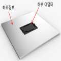
도 1은 본 명세서의 일 실시상태에 따른 OLED 조명 엔진이 조립된 상태를 나타낸 것이다. 구체적으로, 도 1은 제2 하우징이 도시되도록 OLED 조명 엔진을 나타낸 것이다.1 shows an assembled state of an OLED lighting engine according to an embodiment of the present invention. Specifically, Figure 1 shows an OLED lighting engine such that the second housing is shown.
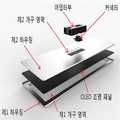
도 2는 본 명세서의 일 실시상태에 따른 OLED 조명 엔진이 분해된 상태를 나타낸 것이다. 구체적으로, 도 2는 도 1에 따른 OLED 조명 엔진을 분해한 것을 나타낸 것이다. 도 2에 있어서, OLED 조명 패널부가 제1 하우징과 제2 하우징에 의하여 수용되고, OLED 조명 패널부의 발광면은 제1 개구 영역에 의하여 외부에 노출되며, 하부 어댑터는 제2 개구부에 의하여 OLED 조명 패널과 외부 전원을 연결할 수 있다.Fig. 2 shows a state in which an OLED lighting engine according to an embodiment of the present invention is disassembled. Specifically, FIG. 2 shows an exploded view of the OLED lighting engine according to FIG. 2, the OLED lighting panel portion is received by the first housing and the second housing, the light emitting surface of the OLED lighting panel portion is exposed to the outside by the first opening region, And an external power supply.
도 1 내지 도 4에 있어서, OLED 조명 패널과 하부 어댑터의 전기적 연결 수단은 생략되었다.1 to 4, the electrical connection means of the OLED lighting panel and the lower adapter is omitted.
도 3은 본 명세서의 일 실시상태에 따른 OLED 조명 엔진이 조립된 상태를 나타낸 것이다. 구체적으로, 도 3은 제2 하우징이 도시되도록 OLED 조명 엔진을 나타낸 것이다.3 shows an assembled state of an OLED lighting engine according to an embodiment of the present invention. Specifically, Figure 3 illustrates an OLED lighting engine such that the second housing is shown.
도 4는 본 명세서의 일 실시상태에 따른 OLED 조명 엔진이 분해된 상태를 나타낸 것이다. 도 4에 있어서, OLED 조명 패널부가 제1 하우징과 제2 하우징에 의하여 수용되고, OLED 조명 패널부의 발광면은 제1 개구 영역에 의하여 외부에 노출되며, 어댑터부는 제2 개구부 및 커넥터를 통하여 OLED 조명 패널과 외부 전원을 연결할 수 있다.FIG. 4 shows a state in which the OLED lighting engine according to an embodiment of the present invention is disassembled. 4, the OLED lighting panel portion is received by the first housing and the second housing, the light emitting surface of the OLED lighting panel portion is exposed to the outside by the first opening region, and the adapter portion is connected to the OLED lighting The panel can be connected to an external power source.
도 1 내지 도 4에 있어서, OLED 조명 패널과 하부 어댑터의 전기적 연결 수단은 생략되었다.1 to 4, the electrical connection means of the OLED lighting panel and the lower adapter is omitted.
Claims (16)
Translated fromKorean상기 하우징부는, 상기 OLED 조명 패널부의 발광면의 적어도 일 영역을 노출시키는 제1 개구 영역을 구비한 제1 하우징, 및 상기 커넥션부의 외부 단자부를 노출시키는 제2 개구 영역을 구비한 제2 하우징을 포함하며,
상기 제1 하우징의 단부 중 적어도 일부와 상기 제2 하우징의 단부 중 적어도 일부가 서로 체결되는 OLED 조명 엔진.An OLED lighting panel part having a light emitting surface; A housing portion accommodating the OLED lighting panel portion; And a connection unit provided on an opposite surface of the light emitting surface of the OLED lighting panel unit and having an external terminal unit electrically connected to the OLED lighting panel unit and electrically connected to an external power source,
The housing portion includes a first housing having a first opening region for exposing at least one region of the light emitting surface of the OLED lighting panel portion and a second housing having a second opening region for exposing an external terminal portion of the connection portion In addition,
Wherein at least a portion of the end of the first housing and at least a portion of the end of the second housing are fastened to each other.
상기 OLED 조명 패널부와 상기 커넥션부는 배선을 통하여 전기적으로 연결되는 것인 OLED 조명 엔진.The method according to claim 1,
Wherein the OLED lighting panel portion and the connection portion are electrically connected through wiring.
상기 OLED 조명 패널부 및 상기 커넥션부 중 적어도 하나는 상기 하우징부에 고정되어 구비되는 것인 OLED 조명 엔진.The method according to claim 1,
Wherein at least one of the OLED lighting panel portion and the connection portion is fixed to the housing portion.
상기 어댑터부는, 상기 OLED 조명 패널부와 전기적으로 연결되는 하부 어댑터, 및 외부 전원과 전기적으로 연결되는 외부 단자부를 구비한 상부 어댑터를 포함하며,
상기 상부 어댑터는 상기 하부 어댑터와 분리 가능하게 결합되고,
상기 하부 어댑터와 상기 상부 어댑터는 각각 상기 상부 어댑터와 상기 하부 어댑터가 서로 전기적으로 연결되기 위한 내부 단자부를 포함하며,
상기 하우징부는, 상기 OLED 조명 패널부의 발광면의 적어도 일 영역을 노출시키는 제1 개구 영역을 구비한 제1 하우징, 및 상기 하부 어댑터의 적어도 일 영역을 노출시키는 제2 개구 영역을 구비한 제2 하우징을 포함하고,
상기 제1 하우징의 단부 중 적어도 일부와 상기 제2 하우징의 단부 중 적어도 일부가 서로 체결되는 OLED 조명 엔진.An OLED lighting panel part having a light emitting surface; A housing portion accommodating the OLED lighting panel portion; And an adapter unit provided on an opposite side of the light emitting surface of the OLED panel unit and electrically connected to the OLED lighting panel unit,
The adapter unit includes an upper adapter having a lower adapter electrically connected to the OLED lighting panel unit and an external terminal unit electrically connected to an external power source,
The upper adapter being detachably coupled to the lower adapter,
The lower adapter and the upper adapter each include an internal terminal portion for electrically connecting the upper adapter and the lower adapter to each other,
Wherein the housing portion includes a first housing having a first opening region for exposing at least one region of the light emitting surface of the OLED lighting panel portion and a second opening region for exposing at least one region of the lower adapter, / RTI >
Wherein at least a portion of the end of the first housing and at least a portion of the end of the second housing are fastened to each other.
상기 OLED 조명 패널부와 상기 하부 어댑터는 배선을 통하여 전기적으로 연결되는 것인 OLED 조명 엔진.The method of claim 4,
Wherein the OLED lighting panel portion and the bottom adapter are electrically connected through wiring.
상기 OLED 조명 패널부 및 상기 하부 어댑터 중 적어도 하나는 상기 하우징부에 고정되어 구비되는 것인 OLED 조명 엔진.The method of claim 4,
Wherein at least one of the OLED lighting panel portion and the lower adapter is fixed to the housing portion.
상기 하부 어댑터는 제1 체결부를 포함하고, 상기 상부 어댑터는 제2 체결부를 포함하며, 상기 제1 체결부와 상기 제2 체결부는 서로 착탈 가능한 것인 OLED 조명 엔진.The method of claim 4,
Wherein the lower adapter includes a first fastening portion, the upper adapter includes a second fastening portion, and the first fastening portion and the second fastening portion are detachable from each other.
상기 제1 체결부 및 상기 제2 체결부 중, 어느 하나는 오목부를 포함하고 다른 하나는 볼록부를 포함하며, 상기 오목부와 볼록부는 서로 맞물려 결합 가능한 것인 OLED 조명 엔진.The method of claim 7,
Wherein one of the first fastening portion and the second fastening portion includes a concave portion and the other includes a convex portion, wherein the concave portion and the convex portion are engageable and engageable with each other.
상기 제1 체결부 및 상기 제2 체결부는 슬라이딩 체결에 의하여 착탈 가능한 것인 OLED 조명 엔진.The method of claim 7,
Wherein the first fastening portion and the second fastening portion are detachable by sliding fastening.
상기 제1 체결부 및 상기 제2 체결부는 서로 맞물린 상태에서 일 방향으로 힘을 가하는 경우, 결합 또는 분리되는 것인 OLED 조명 엔진.The method of claim 7,
Wherein the first fastening portion and the second fastening portion are engaged or separated when a force is applied in one direction in a state where the first fastening portion and the second fastening portion are engaged with each other.
상기 하부 어댑터 및 상부 어댑터 중 적어도 하나는 DC/DC 컨버터를 포함하는 것인 OLED 조명 엔진.The method of claim 4,
Wherein at least one of the lower adapter and the upper adapter includes a DC / DC converter.
상기 제1 하우징 및 상기 제2 하우징 중 어느 하나는 측면에 1 이상의 오목부가 구비되고,
상기 제1 하우징 및 상기 제2 하우징 중 다른 하나는 측면에 1 이상의 볼록부가 구비되며,
상기 오목부와 상기 볼록부는 서로 맞물려 상기 제1 하우징과 상기 제2 하우징을 체결하는 것인 OLED 조명 엔진.The method according to claim 1 or 4,
Wherein at least one of the first housing and the second housing has at least one concave portion on a side surface thereof,
Wherein one of the first housing and the second housing has at least one convex portion on a side surface thereof,
And the concave portion and the convex portion are engaged with each other to fasten the first housing and the second housing.
상기 하우징부의 두께는 2 ㎜ 이상 5 ㎜ 이하인 것인 OLED 조명 엔진.The method according to claim 1 or 4,
Wherein the thickness of the housing portion is 2 mm or more and 5 mm or less.
상기 제1 하우징의 상기 제1 개구 영역이 구비되는 동일 평면 상에 구비되는 베젤 영역의 베젤폭은 0.5 ㎝ 이상 1 ㎝ 이하인 것인 OLED 조명 엔진.The method according to claim 1 or 4,
Wherein a bezel width of the bezel region provided on the same plane on which the first opening region of the first housing is provided is 0.5 cm or more and 1 cm or less.
상기 하우징부는 알루미늄 및 스테인레스 스틸로 이루어진 군에서 선택되는 1종 이상의 물질을 포함하는 것인 OLED 조명 엔진.The method according to claim 1 or 4,
Wherein the housing portion comprises at least one material selected from the group consisting of aluminum and stainless steel.
Priority Applications (1)
| Application Number | Priority Date | Filing Date | Title |
|---|---|---|---|
| KR1020150008900AKR20160089219A (en) | 2015-01-19 | 2015-01-19 | Oled light engine |
Applications Claiming Priority (1)
| Application Number | Priority Date | Filing Date | Title |
|---|---|---|---|
| KR1020150008900AKR20160089219A (en) | 2015-01-19 | 2015-01-19 | Oled light engine |
Publications (1)
| Publication Number | Publication Date |
|---|---|
| KR20160089219Atrue KR20160089219A (en) | 2016-07-27 |
Family
ID=56617109
Family Applications (1)
| Application Number | Title | Priority Date | Filing Date |
|---|---|---|---|
| KR1020150008900ACeasedKR20160089219A (en) | 2015-01-19 | 2015-01-19 | Oled light engine |
Country Status (1)
| Country | Link |
|---|---|
| KR (1) | KR20160089219A (en) |
Citations (1)
| Publication number | Priority date | Publication date | Assignee | Title |
|---|---|---|---|---|
| KR20070093881A (en) | 2006-03-14 | 2007-09-19 | 주식회사 엘지화학 | High efficiency organic light emitting device and its manufacturing method |
- 2015
- 2015-01-19KRKR1020150008900Apatent/KR20160089219A/ennot_activeCeased
Patent Citations (1)
| Publication number | Priority date | Publication date | Assignee | Title |
|---|---|---|---|---|
| KR20070093881A (en) | 2006-03-14 | 2007-09-19 | 주식회사 엘지화학 | High efficiency organic light emitting device and its manufacturing method |
Similar Documents
| Publication | Publication Date | Title |
|---|---|---|
| US11846394B2 (en) | LED-based replacement for fluorescent light source | |
| JP4965598B2 (en) | Separate light-emitting diode light tube | |
| KR100923982B1 (en) | LED fluorescent lamp type fluorescent lamp | |
| US20150029711A1 (en) | Straight tube light-emitting lamp | |
| KR20120040635A (en) | Lighting apparatus | |
| EP2986888B1 (en) | Retrofit organic light emitting diode (oled) light source | |
| JPWO2013038947A1 (en) | lighting equipment | |
| KR100996145B1 (en) | A led lighting apparatus for indoors | |
| US10094539B2 (en) | Fixture and LED system with same | |
| KR101812326B1 (en) | Washer and power supplied illumination device through washer | |
| KR20160089219A (en) | Oled light engine | |
| KR20090102026A (en) | Safety led lighting fitting from short circuit | |
| JP6799811B2 (en) | lighting equipment | |
| KR101124533B1 (en) | A led lighting lamp having an easy assembly structure for switching mode power supply | |
| JP6618009B2 (en) | lighting equipment | |
| KR101370092B1 (en) | Mounting device for led lighting lamp | |
| KR101181341B1 (en) | LED flat light | |
| JP5455950B2 (en) | Lighting fixture for construction | |
| TW201301943A (en) | Isolated capacitor drive circuit for thin-film solid-state lighting | |
| CN112303521A (en) | Lighting lamp | |
| KR20110059290A (en) | Lighting equipment | |
| JP2009110926A (en) | Lighting device | |
| JP2020135995A (en) | lighting equipment | |
| KR20120126578A (en) | A LED lamp | |
| JP2008084555A (en) | Light emitting panel type lighting apparatus |
Legal Events
| Date | Code | Title | Description |
|---|---|---|---|
| PA0109 | Patent application | Patent event code:PA01091R01D Comment text:Patent Application Patent event date:20150119 | |
| N231 | Notification of change of applicant | ||
| PN2301 | Change of applicant | Patent event date:20160325 Comment text:Notification of Change of Applicant Patent event code:PN23011R01D | |
| PG1501 | Laying open of application | ||
| A201 | Request for examination | ||
| PA0201 | Request for examination | Patent event code:PA02012R01D Patent event date:20180213 Comment text:Request for Examination of Application Patent event code:PA02011R01I Patent event date:20150119 Comment text:Patent Application | |
| E902 | Notification of reason for refusal | ||
| PE0902 | Notice of grounds for rejection | Comment text:Notification of reason for refusal Patent event date:20190429 Patent event code:PE09021S01D | |
| AMND | Amendment | ||
| E601 | Decision to refuse application | ||
| PE0601 | Decision on rejection of patent | Patent event date:20191125 Comment text:Decision to Refuse Application Patent event code:PE06012S01D Patent event date:20190429 Comment text:Notification of reason for refusal Patent event code:PE06011S01I | |
| AMND | Amendment | ||
| PX0901 | Re-examination | Patent event code:PX09011S01I Patent event date:20191125 Comment text:Decision to Refuse Application Patent event code:PX09012R01I Patent event date:20190701 Comment text:Amendment to Specification, etc. | |
| PX0601 | Decision of rejection after re-examination | Comment text:Decision to Refuse Application Patent event code:PX06014S01D Patent event date:20200224 Comment text:Amendment to Specification, etc. Patent event code:PX06012R01I Patent event date:20200113 Comment text:Decision to Refuse Application Patent event code:PX06011S01I Patent event date:20191125 Comment text:Amendment to Specification, etc. Patent event code:PX06012R01I Patent event date:20190701 Comment text:Notification of reason for refusal Patent event code:PX06013S01I Patent event date:20190429 |