KR20160089013A - Display device and driving method thereof - Google Patents
Display device and driving method thereofDownload PDFInfo
- Publication number
- KR20160089013A KR20160089013AKR1020150008162AKR20150008162AKR20160089013AKR 20160089013 AKR20160089013 AKR 20160089013AKR 1020150008162 AKR1020150008162 AKR 1020150008162AKR 20150008162 AKR20150008162 AKR 20150008162AKR 20160089013 AKR20160089013 AKR 20160089013A
- Authority
- KR
- South Korea
- Prior art keywords
- signal
- electrodes
- touch
- electrode
- driving
- Prior art date
- Legal status (The legal status is an assumption and is not a legal conclusion. Google has not performed a legal analysis and makes no representation as to the accuracy of the status listed.)
- Granted
Links
Images


Classifications
- G—PHYSICS
- G06—COMPUTING OR CALCULATING; COUNTING
- G06F—ELECTRIC DIGITAL DATA PROCESSING
- G06F3/00—Input arrangements for transferring data to be processed into a form capable of being handled by the computer; Output arrangements for transferring data from processing unit to output unit, e.g. interface arrangements
- G06F3/01—Input arrangements or combined input and output arrangements for interaction between user and computer
- G06F3/03—Arrangements for converting the position or the displacement of a member into a coded form
- G06F3/041—Digitisers, e.g. for touch screens or touch pads, characterised by the transducing means
- G06F3/0416—Control or interface arrangements specially adapted for digitisers
- G06F3/04166—Details of scanning methods, e.g. sampling time, grouping of sub areas or time sharing with display driving
- G06F3/041662—Details of scanning methods, e.g. sampling time, grouping of sub areas or time sharing with display driving using alternate mutual and self-capacitive scanning
- G—PHYSICS
- G06—COMPUTING OR CALCULATING; COUNTING
- G06F—ELECTRIC DIGITAL DATA PROCESSING
- G06F3/00—Input arrangements for transferring data to be processed into a form capable of being handled by the computer; Output arrangements for transferring data from processing unit to output unit, e.g. interface arrangements
- G06F3/01—Input arrangements or combined input and output arrangements for interaction between user and computer
- G06F3/03—Arrangements for converting the position or the displacement of a member into a coded form
- G06F3/041—Digitisers, e.g. for touch screens or touch pads, characterised by the transducing means
- G06F3/044—Digitisers, e.g. for touch screens or touch pads, characterised by the transducing means by capacitive means
- G06F3/0446—Digitisers, e.g. for touch screens or touch pads, characterised by the transducing means by capacitive means using a grid-like structure of electrodes in at least two directions, e.g. using row and column electrodes
- G—PHYSICS
- G06—COMPUTING OR CALCULATING; COUNTING
- G06F—ELECTRIC DIGITAL DATA PROCESSING
- G06F3/00—Input arrangements for transferring data to be processed into a form capable of being handled by the computer; Output arrangements for transferring data from processing unit to output unit, e.g. interface arrangements
- G06F3/01—Input arrangements or combined input and output arrangements for interaction between user and computer
- G06F3/03—Arrangements for converting the position or the displacement of a member into a coded form
- G06F3/041—Digitisers, e.g. for touch screens or touch pads, characterised by the transducing means
- G06F3/044—Digitisers, e.g. for touch screens or touch pads, characterised by the transducing means by capacitive means
- G—PHYSICS
- G06—COMPUTING OR CALCULATING; COUNTING
- G06F—ELECTRIC DIGITAL DATA PROCESSING
- G06F3/00—Input arrangements for transferring data to be processed into a form capable of being handled by the computer; Output arrangements for transferring data from processing unit to output unit, e.g. interface arrangements
- G06F3/01—Input arrangements or combined input and output arrangements for interaction between user and computer
- G06F3/03—Arrangements for converting the position or the displacement of a member into a coded form
- G06F3/041—Digitisers, e.g. for touch screens or touch pads, characterised by the transducing means
- G06F3/0416—Control or interface arrangements specially adapted for digitisers
- G06F3/04166—Details of scanning methods, e.g. sampling time, grouping of sub areas or time sharing with display driving
- G—PHYSICS
- G09—EDUCATION; CRYPTOGRAPHY; DISPLAY; ADVERTISING; SEALS
- G09G—ARRANGEMENTS OR CIRCUITS FOR CONTROL OF INDICATING DEVICES USING STATIC MEANS TO PRESENT VARIABLE INFORMATION
- G09G5/00—Control arrangements or circuits for visual indicators common to cathode-ray tube indicators and other visual indicators
- G09G5/003—Details of a display terminal, the details relating to the control arrangement of the display terminal and to the interfaces thereto
Landscapes
- Engineering & Computer Science (AREA)
- Theoretical Computer Science (AREA)
- General Engineering & Computer Science (AREA)
- Physics & Mathematics (AREA)
- General Physics & Mathematics (AREA)
- Human Computer Interaction (AREA)
- Computer Hardware Design (AREA)
- Position Input By Displaying (AREA)
Abstract
Description
Translated fromKorean본 발명은 표시 장치 및 그 구동 방법에 관한 것이다.The present invention relates to a display apparatus and a driving method thereof.
일반적으로, 액정 표시 장치(liquid crystal display, LCD), 유기 발광 표시 장치(organic light emitting diode display) 등의 표시 패널은 복수의 화소에 연결되어 있는 복수의 게이트 라인 및 복수의 데이터 라인을 포함한다. 복수의 화소는 게이트 라인과 데이터 라인의 교차점에 형성된다. 복수의 게이트 라인에 게이트 온 전압의 게이트 신호가 순차적으로 인가될 때, 게이트 온 전압의 게이트 신호에 대응하여 복수의 데이터 라인에 데이터 전압이 인가되어 복수의 화소에 영상 데이터가 기입된다.In general, a display panel such as a liquid crystal display (LCD) or an organic light emitting diode (OLED) display includes a plurality of gate lines and a plurality of data lines connected to a plurality of pixels. A plurality of pixels are formed at the intersections of the gate lines and the data lines. When a gate signal of a gate-on voltage is sequentially applied to a plurality of gate lines, a data voltage is applied to a plurality of data lines corresponding to a gate signal of a gate-on voltage to write image data into a plurality of pixels.
터치 센서는 사용자의 터치 위치를 인지하여 사용자의 명령을 입력할 수 있다. 터치 센서는 표시 패널의 전면에 구비되거나 표시 패널에 내장되어, 손이나 물체가 터치하는 위치를 파악하여 입력 신호를 판단한다. 터치 센서의 구현 방식 중 하나인 정전용량 방식이 주로 사용되고 있다. 정전용량 방식은 터치 여부에 따라 전극과 손가락 등의 도전성 물체 사이에 형성되는 정전용량의 변화를 감지하는 방식으로, 복수의 감지 라인에 터치 검출을 위한 터치 검출 신호를 순차적으로 인가하여 터치 위치의 정전용량의 변화를 감지한다.The touch sensor recognizes the touch position of the user and can input a command of the user. The touch sensor is provided on the front surface of the display panel or built in the display panel, and determines the input signal by grasping the position where the hand or the object touches. One of the implementation methods of the touch sensor, the capacitance type, is mainly used. The electrostatic capacity type is a method of sensing a change in electrostatic capacity formed between an electrode and a conductive object such as a finger depending on whether a touch is performed. The touch sensing signal for touch detection is sequentially applied to a plurality of sensing lines, And detects a change in capacity.
이러한 정전 용량 방식은 자기 정전 용량(self capacitance) 방식과 상호 정전 용량(mutual capacitance) 방식이 있다.Such a capacitance method has a self capacitance method and a mutual capacitance method.
자기 정전 용량 방식은 x축 방향 및 y축 방향으로 모두 전압을 가하여 자신의 전압 변화를 측정하여 정전 용량을 검출한다. 그리고 상호 정전 용량 방식은 x축 방향에 전압을 가하여 x축 방향과 교차하는 y축 방향에 유도된 전압을 검출하여 정전 용량을 검출한다.In the self-capacitance method, a voltage is applied in both the x-axis direction and the y-axis direction to measure the voltage change of the self-capacitance type, thereby detecting the capacitance. In the reciprocal capacitance method, a voltage is applied in the x-axis direction, and a voltage induced in the y-axis direction intersecting the x-axis direction is detected to detect the electrostatic capacitance.
이때, 자기 정전 용량 방식은 감도가 높고, 따라서 호버링(Hovering) 기능이 가능하다. 하지만 멀티 터치(Multi touch)시 예기치 않은 터치 현상, 즉 허깨비 포인트(ghost point)가 발생할 수 있어 센싱이 원할하지 않다.At this time, the self-capacitance method has a high sensitivity, and thus, a hovering function is possible. However, in case of multi touch, an unexpected touch phenomenon, that is, a ghost point may occur, which makes sensing difficult.
상호 정전 용량 방식은 자기 정전 용량 방식에 비해 감도는 낮으나 멀티 터치가 가능하다. 다만, 감도가 낮아 호버링 등의 민감한 기능이 제한적이다.The reciprocal capacitance method is less sensitive than the self capacitance method, but multi-touch is possible. However, due to low sensitivity, sensitive functions such as hovering are limited.
따라서, 본 발명이 이루고자 하는 기술적 과제는 자기 정전 용량 방식과 상호 정전 용량 방식을 융합하여 복합 터치 센싱 방식이 가능한 표시 장치 및 그 구동 방법을 제공하는 것이다.SUMMARY OF THE INVENTION Accordingly, the present invention has been made in view of the above problems, and an object of the present invention is to provide a display device and a method of driving the same that can perform a complex touch sensing method by fusing a self-capacitance type and a mutual capacitance type.
본 발명의 하나의 특징에 따르면, 표시 장치는 복수의 제1 전극, 상기 복수의 제1 전극과 교차되는 복수의 제2 전극, 그리고 상기 복수의 제1 전극의 일단에 제1 구동 신호를 인가하고, 상기 복수의 제2 전극에 선택적으로 제2 구동 신호를 인가하며, 상기 제1 구동 신호가 인가된 적어도 하나의 제1 전극 및 상기 적어도 하나의 제1 전극과 교차하되 상기 제2 구동 신호가 인가된 복수의 제2 전극에 대해 자기 정전 용량을 검출하며, 상기 적어도 하나의 제1 전극 및 상기 적어도 하나의 제1 전극과 교차하되 상기 제2 구동 신호가 인가되지 않은 복수의 제2 전극에 대해 상호 정전 용량을 검출하는 터치 컨트롤러를 포함한다.According to an aspect of the present invention, a display device includes a plurality of first electrodes, a plurality of second electrodes intersecting with the plurality of first electrodes, and a first driving signal to one end of the plurality of first electrodes A second driving signal is applied selectively to the plurality of second electrodes, and the second driving signal is applied to the at least one first electrode and the at least one first electrode to which the first driving signal is applied, Detecting at least one first electrode and a plurality of second electrodes crossing the at least one first electrode and not applying the second driving signal to the plurality of second electrodes, And a touch controller for detecting capacitance.
상기 터치 컨트롤러는,The touch controller includes:
상기 적어도 하나의 제1 전극의 타단으로부터 제1 감지 신호를 획득하고, 상기 적어도 하나의 제1 전극과 교차하되 상기 제2 구동 신호가 인가된 복수의 제2 전극으로부터 제2 감지 신호를 획득하는 자기 정전 용량 검출부, 상기 적어도 하나의 제1 전극과 교차하되 상기 제2 구동 신호가 인가되지 않은 복수의 제2 전극으로부터 제3 감지 신호를 획득하는 상호 정전 용량 검출부, 그리고 상기 제1 감지 신호 및 상기 제2 감지 신호를 이용하여 판단된 적어도 하나의 제1 좌표와 상기 제3 감지 신호를 이용하여 판단된 적어도 하나의 제2 좌표가 일치하지 않으면, 상기 제2 좌표를 터치 위치로 결정하는 터치 인식부를 포함할 수 있다.A first sensing signal from the other end of the at least one first electrode and a second sensing signal from the second sensing signal crossing the at least one first electrode and obtaining a second sensing signal from a plurality of second electrodes applied with the second driving signal, A mutual capacitance detection unit for obtaining a third sensing signal from a plurality of second electrodes crossing the at least one first electrode but not applying the second driving signal, And a touch recognition unit for determining the second coordinate as a touch position if at least one first coordinate determined using the second sensing signal and at least one second coordinate determined using the third sensing signal do not match can do.
상기 터치 인식부는,The touch recognition unit recognizes,
상기 제1 감지 신호, 상기 제2 감지 신호 및 상기 제3 감지 신호를 토대로 싱글 터치인지 또는 멀티 터치인지를 판단하여, 멀티 터치로 판단되면, 상기 제1 좌표의 개수와 상기 제2 좌표의 개수를 비교하여 개수가 서로 일치하면 상기 제1 좌표를 터치 위치로 결정하고, 서로 일치하지 않으면 상기 제2 좌표를 터치 위치로 결정할 수 있다.And determines whether the touch sensor is a single touch sensor or a multi touch sensor based on the first sensing signal, the second sensing signal, and the third sensing signal. If it is determined that the touch sensor is multi-touch, the number of the first coordinates and the number of the second coordinates The first coordinate may be determined as the touch position if the numbers are matched with each other, and the second coordinate may be determined as the touch position if the numbers do not coincide with each other.
상기 터치 인식부는,The touch recognition unit recognizes,
싱글 터치로 판단되면, 상기 제1 좌표를 터치 위치로 결정할 수 있다.If it is determined as a single touch, the first coordinate may be determined as the touch position.
상기 제1 구동 신호는 제1 펄스 신호 및 제2 펄스 신호를 포함하고,Wherein the first driving signal includes a first pulse signal and a second pulse signal,
상기 제2 구동 신호는 상기 제1 펄스 신호를 포함하고,Wherein the second driving signal includes the first pulse signal,
상기 자기 정전 용량 검출부는,Wherein the self-
상기 제1 펄스 신호가 공급되는 동안 상기 제1 감지 신호 및 상기 제2 감지 신호를 획득하고,Acquiring the first sensing signal and the second sensing signal while the first pulse signal is supplied,
상기 상호 정전 용량 검출부는,Wherein the mutual capacitance detection unit comprises:
상기 제2 펄스 신호가 공급되는 동안 상기 제3 감지 신호를 획득할 수 있다.The third sensing signal may be acquired while the second pulse signal is supplied.
상기 터치 컨트롤러는,The touch controller includes:
제1 구간 동안 상기 제1 펄스 신호 및 상기 제2 펄스 신호를 순차적으로 상기 복수의 제1 전극의 일단에 인가하고, 상기 제1 구간 동안 상기 제1 펄스 신호를 상기 복수의 제2 전극의 일단에 선택적으로 인가하는 구동부를 더 포함할 수 있다.The first pulse signal and the second pulse signal are sequentially applied to one end of the plurality of first electrodes during a first period and the first pulse signal is applied to one end of the plurality of second electrodes during the first period, And may further include a driving unit for selectively applying the driving signal.
상기 구동부는,The driving unit includes:
상기 제1 구간 동안 상기 제1 펄스 신호와 상기 제2 펄스 신호를 스위칭하여 순차적으로 상기 복수의 제1 전극의 일단에 인가하고, 상기 제1 구간 동안 상기 제1 펄스 신호가 인가되는 복수의 제2 전극을 교대로 스위칭할 수 있다.Wherein the first pulse signal and the second pulse signal are sequentially switched during the first period and applied to one end of the plurality of first electrodes, The electrodes can be alternately switched.
본 발명의 다른 특징에 따르면, 표시 장치의 구동 방법은 복수의 제1 전극, 상기 복수의 제1 전극과 교차되는 복수의 제2 전극 및 상기 복수의 제1 전극 및 상기 복수의 제2 전극에 대해 정전 용량을 검출하여 터치를 인식하는 터치 컨트롤러를 포함하는 표시 장치에서, 상기 복수의 제1 전극의 일단에 제1 구동 신호를 인가하는 단계, 상기 복수의 제2 전극에 선택적으로 제2 구동 신호를 인가하는 단계, 제1 구동 신호가 인가된 적어도 하나의 제1 전극 및 상기 적어도 하나의 제1 전극과 교차하되 상기 제2 구동 신호가 인가된 복수의 제2 전극에 대해 자기 정전 용량을 검출하는 단계, 그리고 상기 적어도 하나의 제1 전극 및 상기 적어도 하나의 제1 전극과 교차하되 상기 제2 구동 신호가 인가되지 않은 복수의 제2 전극에 대해 상호 정전 용량을 검출하는 단계를 포함한다.According to another aspect of the present invention, a method of driving a display device includes a plurality of first electrodes, a plurality of second electrodes intersecting with the plurality of first electrodes, and a plurality of second electrodes intersecting with the plurality of first electrodes and the plurality of second electrodes A display device including a touch controller that detects a capacitance by detecting a capacitance, the method comprising: applying a first driving signal to one end of the plurality of first electrodes; selectively applying a second driving signal to the plurality of second electrodes Detecting at least one first electrode to which a first driving signal is applied and a plurality of second electrodes crossing the at least one first electrode and to which the second driving signal is applied, And detecting mutual capacitance for the plurality of second electrodes crossing the at least one first electrode and the at least one first electrode but not applying the second driving signal It includes.
상기 자기 정전 용량을 검출하는 단계는,Wherein the step of detecting the self-
상기 적어도 하나의 제1 전극의 타단으로부터 제1 감지 신호를 획득하고, 상기 적어도 하나의 제1 전극과 교차하되 상기 제2 구동 신호가 인가된 복수의 제2 전극으로부터 제2 감지 신호를 획득하는 단계를 포함하고,Obtaining a first sense signal from the other end of the at least one first electrode and acquiring a second sense signal from a plurality of second electrodes crossing the at least one first electrode and applied with the second drive signal Lt; / RTI >
상기 상호 정전 용량을 검출하는 단계는,Wherein the step of detecting the reciprocal capacitance comprises:
상기 적어도 하나의 제1 전극과 교차하되 상기 제2 구동 신호가 인가되지 않은 복수의 제2 전극으로부터 제3 감지 신호를 획득하는 단계를 포함하고,And obtaining a third sensing signal from a plurality of second electrodes crossing the at least one first electrode but not applying the second driving signal,
상기 상호 정전 용량을 검출하는 단계 이후,After detecting the mutual capacitance,
상기 제1 감지 신호 및 상기 제2 감지 신호를 이용하여 판단된 적어도 하나의 제1 좌표, 상기 제3 감지 신호를 이용하여 판단된 적어도 하나의 제2 좌표를 이용하여 터치 위치를 인식하는 단계를 더 포함할 수 있다.Recognizing the touch position using at least one first coordinate determined using the first sensing signal and the second sensing signal and using at least one second coordinate determined using the third sensing signal .
상기 터치 위치를 인식하는 단계는,The step of recognizing the touch position includes:
상기 제1 감지 신호, 상기 제2 감지 신호 및 상기 제3 감지 신호를 토대로 싱글 터치인지 또는 멀티 터치인지를 판단하는 단계, 상기 싱글 터치로 판단되면, 상기 제1 감지 신호 및 상기 제2 감지 신호를 이용하여 판단된 제1 좌표를 터치 위치로 결정하는 단계, 그리고 상기 멀티 터치로 판단되면, 복수의 제1 좌표 및 복수의 제2 좌표를 비교한 결과를 토대로 터치 위치를 결정하는 단계를 포함할 수 있다.Determining whether the touch sensor is a single touch sensor or a multi-touch sensor based on the first sensing signal, the second sensing signal, and the third sensing signal; determining whether the first sensing signal and the second sensing signal Determining a first coordinate determined as a touch position by using the first coordinate and a touch position determined based on a result of comparing the first coordinate and the second coordinates when the multi- have.
상기 비교한 결과를 토대로 터치 위치를 결정하는 단계는,Wherein the step of determining the touch position based on the comparison result comprises:
상기 복수의 제1 좌표의 개수와 상기 복수의 제2 좌표의 개수를 비교하여 개수가 서로 일치하는지 판단하는 단계, 상기 개수가 서로 일치하면, 상기 제1 좌표를 터치 위치로 결정하는 단계, 그리고 상기 개수가 서로 일치하지 않으면, 상기 제2 좌표를 터치 위치로 결정하는 단계를 포함할 수 있다.Comparing the number of the first coordinates with the number of the second coordinates to determine whether or not the numbers coincide with each other; determining the first coordinate as the touch position if the numbers coincide with each other; And if the numbers do not match, determining the second coordinate as the touch position.
상기 제1 구동 신호를 인가하는 단계는,Wherein the step of applying the first driving signal comprises:
제1 구간 동안 제1 펄스 신호 및 제2 펄스 신호를 순차적으로 인가하는 단계를 포함하고,Sequentially applying a first pulse signal and a second pulse signal during a first period,
상기 제2 구동 신호를 인가하는 단계는,Wherein the step of applying the second driving signal comprises:
상기 제1 구간 동안 상기 제1 펄스 신호를 인가하는 단계를 포함하며,And applying the first pulse signal during the first period,
상기 자기 정전 용량을 검출하는 단계는,Wherein the step of detecting the self-
상기 제1 펄스 신호가 공급되는 동안 상기 제1 감지 신호 및 상기 제2 감지 신호를 획득하는 단계를 포함하고,And acquiring the first sensing signal and the second sensing signal while the first pulse signal is being supplied,
상기 상호 정전 용량을 검출하는 단계는,Wherein the step of detecting the reciprocal capacitance comprises:
상기 제2 펄스 신호가 공급되는 동안 상기 제3 감지 신호를 획득하는 단계를 포함할 수 있다.And acquiring the third sensing signal while the second pulse signal is being supplied.
상기 순차적으로 인가하는 단계는,Wherein the step of sequentially applying,
상기 제1 펄스 신호 및 상기 제2 펄스 신호의 순서를 서로 교대로 스위칭하여 순차적으로 인가하는 단계를 포함하고,And alternately switching and sequentially applying the order of the first pulse signal and the second pulse signal to each other,
상기 제1 구간 동안 상기 제1 펄스 신호를 인가하는 단계는,Wherein the step of applying the first pulse signal during the first period comprises:
상기 복수의 제2 전극 중에서 상기 제1 펄스 신호가 인가되는 제2 전극을 교대로 스위칭하여 상기 제1 펄스 신호를 인가하는 단계를 포함할 수 있다.And alternately switching the second electrode to which the first pulse signal is applied among the plurality of second electrodes to apply the first pulse signal.
본 발명의 실시예에 따르면, 자기 정전 용량 방식의 장점인 높은 감도와 상호 정전 용량 방식의 장점인 멀티 터치 센싱을 융합한 감도 좋은 복합 터치 인식 시스템을 구현할 수 있다.According to the embodiment of the present invention, it is possible to realize a sensitive touch recognition system that combines high sensitivity, which is an advantage of the self-capacitance type, and multi-touch sensing, which is an advantage of the mutual capacitance type.
또한, 터치 센서(Touch Senser)의 감도를 높이고, 자기 정전 용량 감지(Self Capacitance touch) 방식과 상호 정전 용량 감지(Mutual Capacitance touch) 방식을 동시 구현한다. 따라서, 높은 감도가 장점이 자기 정전 용량 감지 방식을 사용하면서도 자기 정전 용량 감지 방식의 장점이 호버링(Hovering) 기능과 멀티 터치 방식이 장점이 상호 정전 용량 감지 방식을 동시에 적용하여 사용할 수 있다.In addition, the sensitivity of the touch sensor is increased, and the self capacitance touch method and the mutual capacitance touch method are simultaneously implemented. Therefore, the advantage of high sensitivity is that the self capacitance detection method is used, but the advantage of the self capacitance detection method is that the hovering function and the multi touch method can be applied simultaneously with the mutual capacitance sensing method.
또한, 하나의 전극에서 자기 정전 용량 감지 방식과 상호 정전 용량 감지 방식을 스위칭하여 사용 가능하고, 구동 전극과 센싱 전극에서도 스위칭하여 두가지 방식을 모두 동시 구현 가능하다.In addition, it is possible to switch between a self-capacitance detection method and a mutual capacitance detection method in one electrode, and switch between a driving electrode and a sensing electrode, both of which can be implemented simultaneously.
또한, 최초 감도가 좋은 자기 정전 용량 감지 방식으로 센싱(sensing)하고, 허깨비(ghost)가 발생시에만 상호 정전 용량 감지 방식으로 센싱하므로 싱글 터치(single touch) 또는 동일한 라인(line)을 멀티 터치(multi touch) 했을 경우 감도가 높은 장점이 있다.In addition, since the sensing is performed by a self-capacitance sensing method with a good initial sensitivity and by the mutual capacitance sensing method only when a ghost is generated, a single touch or a same line can be applied to a multi- touch) has a high sensitivity.
도 1은 본 발명의 한 실시예에 따른 표시 장치를 도시한 것이고,
도 2는 도 1의 터치 컨트롤러의 세부적인 구성을 나타낸 블록도이며,
도 3은 본 발명의 실시예에 따른 싱글 터치를 나타낸 것이고,
도 4는 본 발명의 한 실시예에 따른 멀티 터치를 나타낸 것이며,
도 5는 본 발명의 다른 실시예에 따른 멀티 터치를 나타낸 것이고,
도 6은 본 발명의 실시예에 따른 터치 인식 예를 나타낸 것이며,
도 7은 본 발명의 한 실시예에 따른 제1 구동 신호의 타이밍 예시도이고,
도 8은 본 발명의 한 실시예에 따른 제2 구동 신호의 타이밍 예시도이며,
도 9 및 도 10은 본 발명의 한 실시예에 따른 복합 터치 센싱 동작을 설명하기 위한 도면이고,
도 11은 본 발명의 다른 실시예에 따른 제1 구동 신호의 타이밍 예시도이며,
도 12는 본 발명의 다른 실시예에 따른 제2 구동 신호의 타이밍 예시도이고,
도 13 및 도 14는 본 발명의 다른 실시예에 따른 복합 터치 센싱 동작을 설명하기 위한 도면이며,
도 15 및 도 16은 본 발명의 실시예에 따른 제2 전극의 복합 터치 센싱 구동 예시도이고,
도 17은 본 발명의 실시예에 따른 표시 장치의 구동 방법을 도시한 흐름도이다.1 shows a display device according to an embodiment of the present invention,
Fig. 2 is a block diagram showing a detailed configuration of the touch controller of Fig. 1,
3 illustrates a single-touch according to an embodiment of the present invention,
4 illustrates a multi-touch according to an embodiment of the present invention,
5 illustrates a multi-touch according to another embodiment of the present invention,
6 shows an example of touch recognition according to an embodiment of the present invention,
7 is a timing diagram of a first drive signal according to an embodiment of the present invention,
8 is a timing diagram of a second drive signal according to an embodiment of the present invention,
9 and 10 are views for explaining a composite touch sensing operation according to an embodiment of the present invention,
11 is a timing diagram of a first drive signal according to another embodiment of the present invention,
12 is a timing diagram of a second drive signal according to another embodiment of the present invention,
13 and 14 are views for explaining a composite touch sensing operation according to another embodiment of the present invention,
FIGS. 15 and 16 are views illustrating a compound touch sensing operation of a second electrode according to an embodiment of the present invention.
17 is a flowchart illustrating a method of driving a display device according to an embodiment of the present invention.
아래에서는 첨부한 도면을 참고로 하여 본 발명의 실시예에 대하여 본 발명이 속하는 기술 분야에서 통상의 지식을 가진 자가 용이하게 실시할 수 있도록 상세히 설명한다. 그러나 본 발명은 여러가지 상이한 형태로 구현될 수 있으며 여기에서 설명하는 실시예에 한정되지 않는다. 그리고 도면에서 본 발명을 명확하게 설명하기 위해서 설명과 관계없는 부분은 생략하였으며, 명세서 전체를 통하여 유사한 부분에 대해서는 유사한 도면 부호를 붙였다.Hereinafter, embodiments of the present invention will be described in detail with reference to the accompanying drawings so that those skilled in the art can easily carry out the present invention. The present invention may, however, be embodied in many different forms and should not be construed as limited to the embodiments set forth herein. In order to clearly illustrate the present invention, parts not related to the description are omitted, and similar parts are denoted by like reference characters throughout the specification.
명세서 전체에서, 어떤 부분이 어떤 구성 요소를 "포함"한다고 할 때, 이는 특별히 반대되는 기재가 없는 한 다른 구성 요소를 제외하는 것이 아니라 다른 구성 요소를 더 포함할 수 있는 것을 의미한다.Throughout the specification, when an element is referred to as "comprising ", it means that it can include other elements as well, without excluding other elements unless specifically stated otherwise.
명세서 전체에서, 어떤 부분이 다른 부분과 "연결"되어 있다고 할 때, 이는 "직접적으로 연결"되어 있는 경우뿐 아니라, 그 중간에 다른 소자를 사이에 두고 "전기적으로 연결"되어 있는 경우도 포함한다. 또한 어떤 부분이 어떤 구성요소를 "포함"한다고 할 때, 이는 특별히 반대되는 기재가 없는 한 다른 구성요소를 제외하는 것이 아니라 다른 구성요소를 더 포함할 수 있는 것을 의미한다.Throughout the specification, when a part is referred to as being "connected" to another part, it includes not only "directly connected" but also "electrically connected" with another part in between . Also, when an element is referred to as "comprising ", it means that it can include other elements as well, without departing from the other elements unless specifically stated otherwise.
이하, 도면을 참조로 하여 본 발명의 실시예에 따른 표시 장치 및 그 구동 방법에 대하여 상세히 설명한다.Hereinafter, a display device and a driving method thereof according to embodiments of the present invention will be described in detail with reference to the drawings.
도 1은 본 발명의 한 실시예에 따른 표시 장치를 도시한 것이고, 도 2는 도 1의 터치 컨트롤러의 세부적인 구성을 나타낸 블록도이며, 도 3은 본 발명의 실시예에 따른 싱글 터치를 나타낸 것이고, 도 4는 본 발명의 한 실시예에 따른 멀티 터치를 나타낸 것이며, 도 5는 본 발명의 다른 실시예에 따른 멀티 터치를 나타낸 것이고, 도 6은 본 발명의 실시예에 따른 터치 인식 예를 나타낸 것이며, 도 7은 본 발명의 한 실시예에 따른 제1 구동 신호의 타이밍 예시도이고, 도 8은 본 발명의 한 실시예에 따른 제2 구동 신호의 타이밍 예시도이며, 도 9 및 도 10은 본 발명의 한 실시예에 따른 복합 터치 센싱 동작을 설명하기 위한 도면이고, 도 11은 본 발명의 다른 실시예에 따른 제1 구동 신호의 타이밍 예시도이며, 도 12는 본 발명의 다른 실시예에 따른 제2 구동 신호의 타이밍 예시도이고, 도 13 및 도 14는 본 발명의 다른 실시예에 따른 복합 터치 센싱 동작을 설명하기 위한 도면이며, 도 15 및 도 16은 본 발명의 실시예에 따른 제2 전극의 복합 터치 센싱 구동 예시도이다.FIG. 1 is a block diagram of a display device according to an embodiment of the present invention, FIG. 2 is a block diagram illustrating a detailed configuration of the touch controller of FIG. 1, and FIG. FIG. 4 shows a multi-touch according to an embodiment of the present invention, FIG. 5 shows a multi-touch according to another embodiment of the present invention, FIG. 6 shows a touch recognition example according to an embodiment of the present invention, FIG. 7 is a timing diagram of a first drive signal according to an embodiment of the present invention, FIG. 8 is a timing diagram of a second drive signal according to an embodiment of the present invention, and FIGS. 9 and 10 FIG. 11 is a timing diagram of a first drive signal according to another embodiment of the present invention, and FIG. 12 is a timing chart for explaining the operation of another embodiment of the present invention The second drive signal FIGS. 13 and 14 are diagrams for explaining a composite touch sensing operation according to another embodiment of the present invention. FIGS. 15 and 16 are timing charts for explaining a composite touch sensing operation of a second electrode according to an embodiment of the present invention. Fig.
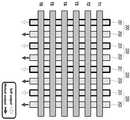
도 1을 참조하면, 표시 장치(1)는 복수의 제1 전극(100), 복수의 제2 전극(200), 제1 배선들(300), 제2 배선들(400), 제3 배선들(500), 제4 배선들(600) 및 터치 컨트롤러(700)를 포함한다.Referring to FIG. 1, a
복수의 제1 전극(100) 및 복수의 제2 전극(200)은 상호 교차하도록 위치한다. 이때, 제1 전극(100)과 제2 전극(200)이 교차하는 부분에는 하나의 터치 센서(TS)가 형성된다.The plurality of
복수의 제1 전극(100)은 제1 방향, 예를 들면, X축 방향으로 길게 형성되어 제1 방향과 교차하는 제2 방향, 예를 들면 Y축 방향으로 복수개 배열되는 N개의 전극일 수 있다. 그리고 복수의 제2 전극(200)은 Y축 방향으로 길게 형성되어 제2 방향과 교차하는 제1 방향을 따라 복수개가 배열되는 N개의 전극일 수 있다.The plurality of
이때, 복수의 제1 전극(100)은 제1 구동 신호가 인가되면, 자기 정전 용량 및 상호 정전 용량으로 교번하여 구동되는 구동 전극(Tx)이다. 복수의 제2 전극(200)은 제2 구동 신호가 인가되는 구동 전극(Tx)과 제2 구동 신호가 인가되지 않는 센싱 전극(Rx)이 교대로 배치된다.At this time, the plurality of
제1 배선들(300)은 복수의 제1 전극(100)의 일단과 터치 컨트롤러(700)를 연결하고 제1 구동 신호를 복수의 제1 전극(100)으로 출력한다.The
제2 배선들(400)은 복수의 제2 전극(200)의 일단과 터치 컨트롤러(700)를 연결한다. 그리고 제2 구동 신호를 복수의 제2 전극(200) 중에서 구동 전극(Tx)으로 동작하는 복수의 제2 전극(200)으로 선택적으로 출력한다.The
제3 배선들(500)은 복수의 제1 전극(100)의 타단과 터치 컨트롤러(700)를 연결한다. 그리고 복수의 제1 전극(2100)의 타단으로부터 출력된 제1 감지 신호를 터치 컨트롤러(700)로 입력한다.The
제4 배선들(600)은 복수의 제2 전극(200)과 터치 컨트롤러(700)를 연결한다. 그리고 복수의 제1 전극(100)과 교차하고 구동 전극(Tx)으로 동작하는 복수의 제2 전극(200)으로부터 출력된 제2 감지 신호를 터치 컨트롤러(700)로 전달한다. 그리고 복수의 제1 전극(100)과 교차하고 센싱 전극(Rx)으로 동작하는 복수의 제2 전극(200)으로부터 출력되는 제3 감지 신호를 터치 컨트롤러(700)로 전달한다.The
터치 컨트롤러(700)는 복수의 제1 전극(100)의 일단에 제1 구동 신호를 인가한다. 그리고 복수의 제2 전극(200)에 선택적으로 제2 구동 신호를 인가한다.The
터치 컨트롤러(700)는 적어도 하나의 제1 전극(100) 및 적어도 하나의 제1 전극(100)과 교차하고 구동 전극(Tx)으로 동작하는 복수의 제2 전극(200)에 대해 자기 정전 용량(Self Capacitance)을 검출한다. 그리고 적어도 하나의 제1 전극(100) 및 적어도 하나의 제1 전극(100)과 교차하되 센싱 전극(Rx)으로 동작하는 복수의 제2 전극(200)에 대해 상호 정전 용량(Mutual Capacitance)을 검출한다.The
터치 컨트롤러(700)는 도 2와 같이 세부적인 구성을 포함할 수 있다.The
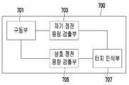
도 2를 참조하면, 터치 컨트롤러(700)는 구동부(701), 자기 정전 용량 검출부(703), 상호 정전 용량 검출부(705) 및 터치 인식부(707)를 포함한다.2, the
도 2를 참조하면, 구동부(701)는 제1 구간 동안 제1 구동 신호를 복수의 제1 전극(100)에 인가한다. 그리고 제2 구동 신호를 복수의 제2 전극(200) 중 일부 제2 2 전극에 인가한다.Referring to FIG. 2, the
자기 정전 용량 검출부(703)는 적어도 하나의 제1 전극(100)의 타단으로부터 제1 감지 신호를 획득한다. 그리고 제1 감지 신호가 출력된 적어도 하나의 제1 전극(100)과 교차하되 제2 구동 신호가 인가된 복수의 제2 전극(200), 즉 구동 전극(Tx)으로 동작하는 제2 전극(200)으로부터 제2 감지 신호를 획득한다.The self-
상호 정전 용량 검출부(705)는 적어도 하나의 제1 전극(100)과 교차하되 제2 구동 신호가 인가되지 않은 복수의 제2 전극(200), 즉, 센싱 전극(Rx)으로 동작하는 제2 전극(200)으로부터 제3 감지 신호를 획득한다.The mutual
터치 인식부(707)는 제1 감지 신호 및 제2 감지 신호를 이용하여 판단된 적어도 하나의 제1 좌표와, 제3 감지 신호를 이용하여 판단된 적어도 하나의 제2 좌표가 일치하지 않으면, 제2 좌표를 터치 위치로 결정한다.If at least one first coordinate determined using the first sensing signal and the second sensing signal does not coincide with at least one second coordinate determined using the third sensing signal, 2 coordinate is determined as the touch position.
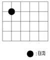
터치 인식부(707)는 제1 좌표 또는 제2 좌표가 각각 하나의 좌표인지 또는 둘 이상의 좌표인지를 판단한다. 즉, 도 3과 같은 싱글 터치(Single touch)인지 또는 도 4와 같은 멀티 터치(Multi touch)인지를 판단한다.The
이때, 싱글 터치로 판단되면, 제1 좌표를 터치 위치로 결정한다. 즉, 싱글 터치의 경우, 자기 정전 용량 센싱 동작을 우선하여 감도 높은 터치를 구현할 수 있다.At this time, if it is determined as a single touch, the first coordinate is determined as the touch position. That is, in the case of a single touch, a high-sensitivity touch can be realized by prioritizing the self-capacitance sensing operation.
반면, 멀티 터치로 판단되면, 제1 좌표의 개수와 제2 좌표의 개수를 비교하여 일치하면 제1 좌표를 터치 위치로 결정하고 일치하지 않으면 제2 좌표를 터치 위치로 결정한다. 즉, 자기 정전 용량 센싱을 통해 인식한 터치 개수와 상호 정전 용량 센싱을 통해 인식한 터치 개수를 비교하여 일치하면 자기 정전 용량 센싱 동작을 우선한다. 그러나 일치하지 않으면 허깨비(Ghost) 포인트가 발생한 것이므로, 이런 경우 상호 정전 용량 센싱 동작을 우선한다.On the other hand, if the number of the first coordinates is compared with the number of the second coordinates, the first coordinate is determined as the touch position, and if not, the second coordinate is determined as the touch position. That is, the number of touches recognized through self-capacitance sensing is compared with the number of touches recognized through mutual capacitance sensing, and if they match, self-capacitance sensing operation takes priority. However, if they do not match, a ghost point is generated. In this case, the mutual capacitance sensing operation takes precedence.
여기서, 멀티 터치의 경우, 제1 좌표의 개수와 제2 좌표의 개수가 일치하는 경우는 도 4와 같이 감도가 좋은 자기 정전 용량 센싱을 통해 판단된 제1 좌표를 유효한 터치 위치로 결정한다.Here, in the case of multi-touch, when the number of the first coordinates coincides with the number of the second coordinates, the first coordinate determined through self-capacitance sensing with good sensitivity is determined as a valid touch position as shown in FIG.
반면, 제1 좌표의 개수와 제2 좌표의 개수가 일치하지 않는 경우는 도 5와 같이 자기 정전 용량 센싱 동작시 허깨비(Ghost) 포인트가 발생한 경우이다. 이런 경우, 터치 인식부(707)는 상호 정전 용량 센싱을 통해 판단된 제2 좌표를 유효한 터치 위치로 결정함으로써, 도 6과 같이 허깨비 포인트는 터치 좌표에서 제외할 수 있다.On the other hand, when the number of the first coordinates does not match the number of the second coordinates, a ghost point occurs in the self-capacitance sensing operation as shown in FIG. In this case, the
이제, 구동부(701)의 타이밍 제어 실시예 별로 복합 터치 센싱 동작, 즉 자기 정전 용량 센싱과 상호 정전 용량 센싱이 융합된 복합 터치 센싱 동작을 설명한다.Now, a complex touch sensing operation, that is, a composite touch sensing operation in which the self capacitance sensing and the mutual capacitance sensing are fused by the timing control embodiment of the
먼저, 본 발명의 하나의 실시예에 따른 복합 터치 센싱 동작을 설명한다.First, a composite touch sensing operation according to an embodiment of the present invention will be described.
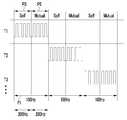
도 7을 참조하면, 제1 구간(P1)은 자기 정전 용량 센싱을 위한 제1 펄스 신호 구간(P3) 및 상호 정전 용량 센싱을 위한 제2 펄스 신호 구간(P5)을 포함한다. 여기서, 제1 펄스 신호는 자기 정전 용량 센싱 구간에서 인가되는 제1 구동 신호 및 제2 구동 신호에 포함된다. 그리고 제2 펄스 신호는 상호 정전 용량 센싱 구간에서 인가되는 제1 구동 신호에 포함된다.Referring to FIG. 7, the first section P1 includes a first pulse signal interval P3 for self-capacitance sensing and a second pulse signal interval P5 for mutual capacitance sensing. Here, the first pulse signal is included in the first driving signal and the second driving signal applied in the self-capacitance sensing period. And the second pulse signal is included in the first driving signal applied in the mutual capacitance sensing period.
구동부(701)는 제1 펄스 신호 구간(P3) 및 제2 펄스 신호 구간(P5) 동안 제1 펄스 신호 및 제2 펄스 신호를 순차적으로 복수의 제1 전극(100)의 일단에 인가한다. 이때, 제1 펄스 신호 및 제2 펄스 신호를 각각 200Hz로 구동하여 빠르게 신호를 인가한다.The driving
도 8을 참조하면, 제2 구동 신호는 제1 구간(P1) 중에서 자기 정전 용량 센싱을 위한 제1 펄스 신호 구간(P3) 중에 복수의 제2 전극(200)의 일단에 선택적으로 인가된다.Referring to FIG. 8, the second driving signal is selectively applied to one end of the plurality of
도 7 및 도 8에서 설명한 제1 구동 신호 및 제2 구동 신호에 따른 센싱 동작을 설명하면 도 9 및 도 10과 같다.The sensing operation according to the first drive signal and the second drive signal described with reference to FIGS. 7 and 8 will now be described with reference to FIGS. 9 and 10. FIG.
먼저, 도 9를 참조하면, 복수의 제1 전극(T1, T2, T3, T4, ... T6)에는 도 4의 제1 펄스 신호가 인가된다. 그리고 복수의 제2 전극 중 일부 제2 전극(T1, T2, T3…)에는 도 4의 제1 펄스 신호가 인가된다. 여기서, 일부 제2 전극(T1, T2, T3…)은 구동 전극(Tx)으로 동작한다.Referring to FIG. 9, the first pulse signal of FIG. 4 is applied to a plurality of first electrodes T1, T2, T3, T4, ..., T6. The first pulse signal of FIG. 4 is applied to some of the second electrodes T1, T2, T3... Of the plurality of second electrodes. Here, some of the second electrodes T1, T2, T3, ... operate as the driving electrode Tx.
이때, 복수의 제1 전극(T1, T2, T3, T4, ... T6)과 일부 제2 전극(T1, T2, T3…)에는 동일한 시간에 제1 펄스 신호가 인가된다. 이러한 제1 펄스 신호가 인가되는 자기 정전 용량 센싱 구간에서는 복수의 제1 전극(T1, T2, T3, T4, ... T6)의 타단으로 제1 감지 신호가 출력된다. 그리고 구동 전극(Tx)으로 동작하는 일부 제2 전극(T1, T2, T3…)에서는 제2 감지 신호가 출력된다. 여기서, 제1 감지 신호 및 제2 감지 신호는 자기 정전 용량 센싱에 따른 감지 신호(Self Output)에 해당된다.At this time, the first pulse signal is applied to the plurality of first electrodes T1, T2, T3, T4, ..., T6 and some of the second electrodes T1, T2, T3 ... at the same time. In the self-capacitance sensing period in which the first pulse signal is applied, the first sensing signal is output to the other end of the plurality of first electrodes T1, T2, T3, T4, ..., T6. And a second sensing signal is output from some of the second electrodes T1, T2, T3, ... operating as the driving electrode Tx. Here, the first sensing signal and the second sensing signal correspond to a sensing signal (Self Output) due to the self-capacitance sensing.
또한, 도 10을 참조하면, 제1 펄스 신호가 인가된 후 복수의 제1 전극(T1, T2, T3, T4, ... T6)에는 도 4의 제2 펄스 신호가 연이어 인가된다. 그리고 도 8에 보인 바와 같이, 도 7의 제2 펄스 신호가 인가되는 동안에는 복수의 제2 전극에는 신호가 인가되지 않는다.Referring to FIG. 10, after the first pulse signal is applied, the second pulse signals of FIG. 4 are sequentially applied to the first electrodes T1, T2, T3, T4, ..., T6. As shown in FIG. 8, no signal is applied to the plurality of second electrodes while the second pulse signal of FIG. 7 is applied.
이와 같이, 제2 펄스 신호가 인가되는 상호 정전 용량 센싱 구간에서는 센싱 전극(Rx)으로 동작하는 제2 전극(R1, R2, ?4)으로부터 제3 감지 신호가 출력된다. 제3 감지 신호는 상호 정전 용량 센싱에 따른 감지 신호(Mutusl Output)에 해당된다.In this way, the third sensing signal is output from the second electrodes (R1, R2,? 4) that operate as the sensing electrode (Rx) in the mutual capacitance sensing period in which the second pulse signal is applied. The third sensing signal corresponds to a sensing signal (Mutusl Output) due to mutual capacitance sensing.
다음, 본 발명의 다른 실시예에 따른 복합 터치 센싱 동작을 설명하면 다음과 같다.Next, a composite touch sensing operation according to another embodiment of the present invention will be described.
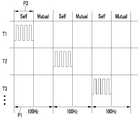
구동부(701)는 제1 구간(P1) 동안 제1 펄스 신호와 제2 펄스 신호를 스위칭하여 순차적으로 복수의 제1 전극(100)의 일단에 인가하고, 제1 구간(P1) 동안 제1 펄스 신호가 인가되는 복수의 제2 전극(200)을 교대로 스위칭할 수 있다. 즉, 복수의 제1 전극(100) 각각은 자기 정전 용량 센싱 동작(Self)과 상호 정전 용량 센싱 동작(Mutual)을 교대로 할 수 있다.The driving
도 11을 참조하면, 도 7에서 설명한 바와 마찬가지로 제1 구간(P1)은 자기 정전 용량 센싱을 위한 제1 펄스 신호 구간(P3) 및 상호 정전 용량 센싱을 위한 제2 펄스 신호 구간(P5)을 포함한다. 그러나 도 7과 반대로 구동부(701)는 제2 펄스 신호를 먼저 보내고 그 다음에 제1 펄스 신호를 보낸다.Referring to FIG. 11, the first section P1 includes a first pulse signal section P3 for self-capacitance sensing and a second pulse signal section P5 for mutual capacitance sensing, as described with reference to FIG. do. 7, however, the driving
그리고 도 12에 보인 바와 같이, 도 8의 제1 펄스 신호가 인가되는 동안 마찬가지로 제1 펄스 신호가 복수의 제2 전극(200) 중 일부 제2 전극(T1, T2, ..)에 인가된다.As shown in FIG. 12, a first pulse signal is applied to some second electrodes T1, T2,... Of the plurality of
도 11 및 도 12에서 설명한 제1 구동 신호 및 제2 구동 신호에 따른 센싱 동작을 설명하면 도 13 및 도 14와 같다.The sensing operation according to the first driving signal and the second driving signal described with reference to FIGS. 11 and 12 will be described with reference to FIGS. 13 and 14. FIG.
먼저, 도 13을 참조하면, 복수의 제1 전극(T1, T2, T3, T4, ... T6)에는 도 11의 제2 펄스 신호가 인가된다. 그리고 도 12에 보인 바와 같이, 도 11의 제2 펄스 신호가 인가되는 동안에는 복수의 제2 전극에는 신호가 인가되지 않는다.13, the second pulse signal of FIG. 11 is applied to the plurality of first electrodes T1, T2, T3, T4, ..., T6. As shown in FIG. 12, no signal is applied to the plurality of second electrodes while the second pulse signal of FIG. 11 is applied.
이와 같이, 제2 펄스 신호가 인가되는 상호 정전 용량 센싱 구간에서는 센싱 전극(Rx)으로 동작하는 제2 전극(R1, R2, ?4)으로부터 제3 감지 신호(Mutusl Output)가 출력된다.In this way, the third sensing signal (Mutusl Output) is outputted from the second electrodes (R1, R2,? 4) operating as the sensing electrode (Rx) in the mutual capacitance sensing period in which the second pulse signal is applied.
또한, 도 14를 참조하면, 제2 펄스 신호가 인가된 후 복수의 제1 전극(T1, T2, T3, T4, ... T6)에는 도 11의 제1 펄스 신호가 연이어 인가된다. 그리고 복수의 제2 전극 중 일부 제2 전극(T1, T2, T3…)에는 도 12의 제1 펄스 신호가 인가된다. 여기서, 일부 제2 전극(T1, T2, T3…)은 구동 전극(Tx)으로 동작한다.14, the first pulse signals of FIG. 11 are sequentially applied to the plurality of first electrodes T1, T2, T3, T4, ..., T6 after the second pulse signal is applied. The first pulse signal of FIG. 12 is applied to some of the second electrodes T1, T2, T3... Of the plurality of second electrodes. Here, some of the second electrodes T1, T2, T3, ... operate as the driving electrode Tx.
이때, 복수의 제1 전극(T1, T2, T3, T4, ... T6)과 일부 제2 전극(T1, T2, T3…)에는 동일한 시간에 제1 펄스 신호가 인가된다. 이러한 제1 펄스 신호가 인가되는 자기 정전 용량 센싱 구간에서는 복수의 제1 전극(T1, T2, T3, T4, ... T6)의 타단으로 제1 감지 신호(Self Output)가 출력된다. 그리고 구동 전극(Tx)으로 동작하는 일부 제2 전극(T1, T2, T3…)에서는 제2 감지 신호(Self Output)가 출력된다.At this time, the first pulse signal is applied to the plurality of first electrodes T1, T2, T3, T4, ..., T6 and some of the second electrodes T1, T2, T3 ... at the same time. In the self-capacitance sensing period in which the first pulse signal is applied, a first sensing signal (Self Output) is output to the other end of the plurality of first electrodes T1, T2, T3, T4, ..., T6. And a second sensing signal (Self Output) is output from some of the second electrodes T1, T2, T3, ... operating as the driving electrode Tx.
또한, 복수의 제2 전극(200)은 제2 구동 신호가 인가되는 구동 전극(Tx)과 제2 구동 신호가 인가되지 않는 센싱 전극(Rx)으로 구성되는데, 이때, 구동 전극(Tx) 및 센싱 전극(Rx)으로 동작하는 제2 전극(200)은 교번할 수 있다. 즉, 복수의 제2 전극(200)은 제2 구동 신호의 인가 유무에 따라 자기 정전 용량 센싱 동작(Self)과 상호 정전 용량 센싱 동작(Mutual)을 교대로 할 수 있다.The plurality of
도 15를 참조하면, 제2-1 구동 전극(201)은 제2 구동 신호가 인가되는 구동 전극(Tx)으로 동작하고, 제2-2 구동 전극(203)은 센싱 전극(Rx)으로 동작한다. 이때에는 제2-1 구동 전극(201)은 제2 감지 신호(Self Output)를 출력하고 제2-2 구동 전극(203)은 제3 감지 신호(Mutusl Output)를 출력한다.Referring to FIG. 15, the second-1
도 16을 참조하면, 제2-1 구동 전극(201)은 센싱 전극(Rx)으로 동작하고, 제2-2 구동 전극(203)은 제2 구동 신호가 인가되는 구동 전극(Tx)으로 동작하한다. 이때에는 제2-1 구동 전극(201)은 제3 감지 신호(Mutusl Output)를 출력하고, 제2-2 구동 전극(203)은 제2 감지 신호(Self Output)를 출력한다.16, the 2-1
지금까지 설명한 구성을 토대로 표시 장치를 구동하는 과정을 설명한다.A process of driving the display device on the basis of the configuration described so far will be described.
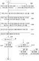
도 17은 본 발명의 실시예에 따른 표시 장치의 구동 방법을 도시한 흐름도이다.17 is a flowchart illustrating a method of driving a display device according to an embodiment of the present invention.
도 17을 참조하면, 구동부(701)는 제1 구간(P1) 동안 제1 구동 신호를 복수의 제1 전극(100)의 일단에 순차적으로 인가한다(S101).Referring to FIG. 17, the driving
구동부(701)는 제1 구간(P1) 동안 제2 구동 신호를 복수의 제2 전극(200)의 일단에 선택적으로 인가한다(S103).The driving
자기 정전 용량 검출부(703)는 제1 구동 신호가 인가된 적어도 하나의 제1 전극(100)의 타단으로부터 제1 감지 신호를 검출한다(S105). 그리고 제1 감지 신호가 검출된 적어도 하나의 제1 전극(100)과 교차하되 제2 구동 신호가 인가된 복수의 제2 전극(200)의 타단으로부터 제2 감지 신호를 검출한다(107).The electrostatic
상호 정전 용량 검출부(705)는 제1 구동 신호가 인가된 적어도 하나의 제1 전극(100)과 교차하되 제2 구동 신호가 인가되지 않은 복수의 제2 전극(200)의 타단으로부터 제3 감지 신호를 검출한다(S109).The mutual
터치 인식부(707)는 제1 감지 신호 및 제2 감지 신호를 토대로 적어도 하나의 제1 터치 좌표를 판단(S111)하고, 제3 감지 신호를 토대로 적어도 하나의 제2 터치 좌표를 판단(S113)한다.The
터치 인식부(707)는 적어도 하나의 제1 터치 좌표 및 적어도 하나의 제2 터치 좌표가 싱글 터치인지 또는 멀티 터치인지를 판단한다(S115).The
싱글 터치로 판단되면, 터치 인식부(707)는 제1 터치 좌표를 터치 위치로 결정한다(S117).If it is determined as a single touch, the
멀티 터치로 판단되면, 터치 인식부(707)는 제1 터치 좌표의 개수와 제2 터치 좌표의 개수가 일치하는지를 판단한다(S119).If it is determined that the number of the first touch coordinates is equal to the number of the second touch coordinates (S119), the
이때, 개수가 일치하면, 제1 터치 좌표를 터치 위치로 결정한다(S121).At this time, if the numbers match, the first touch coordinates are determined as the touch positions (S121).
반면, 개수가 일치하지 않으면, 제2 터치 좌표를 터치 위치로 결정한다(S123).On the other hand, if the numbers do not match, the second touch coordinate is determined as the touch position (S123).
이상에서 설명한 본 발명의 실시예는 장치 및 방법을 통해서만 구현이 되는 것은 아니며, 본 발명의 실시예의 구성에 대응하는 기능을 실현하는 프로그램 또는 그 프로그램이 기록된 기록 매체를 통해 구현될 수도 있다.The embodiments of the present invention described above are not implemented only by the apparatus and method, but may be implemented through a program for realizing the function corresponding to the configuration of the embodiment of the present invention or a recording medium on which the program is recorded.
이상에서 본 발명의 실시예에 대하여 상세하게 설명하였지만 본 발명의 권리범위는 이에 한정되는 것은 아니고 다음의 청구범위에서 정의하고 있는 본 발명의 기본 개념을 이용한 당업자의 여러 변형 및 개량 형태 또한 본 발명의 권리범위에 속하는 것이다.While the present invention has been particularly shown and described with reference to exemplary embodiments thereof, it is to be understood that the invention is not limited to the disclosed exemplary embodiments, It belongs to the scope of right.
Claims (13)
Translated fromKorean상기 복수의 제1 전극과 교차되는 복수의 제2 전극, 그리고
상기 복수의 제1 전극의 일단에 제1 구동 신호를 인가하고, 상기 복수의 제2 전극에 선택적으로 제2 구동 신호를 인가하며, 상기 제1 구동 신호가 인가된 적어도 하나의 제1 전극 및 상기 적어도 하나의 제1 전극과 교차하되 상기 제2 구동 신호가 인가된 복수의 제2 전극에 대해 자기 정전 용량을 검출하며, 상기 적어도 하나의 제1 전극 및 상기 적어도 하나의 제1 전극과 교차하되 상기 제2 구동 신호가 인가되지 않은 복수의 제2 전극에 대해 상호 정전 용량을 검출하는 터치 컨트롤러
를 포함하는 표시 장치.A plurality of first electrodes,
A plurality of second electrodes crossing the plurality of first electrodes, and
At least one first electrode to which a first driving signal is applied and a second electrode to which a second driving signal is applied, Detecting at least one first electrode and a plurality of second electrodes crossing the at least one first electrode and applying the second driving signal to each other, intersecting the at least one first electrode and the at least one first electrode, A touch controller which detects mutual capacitance with respect to a plurality of second electrodes to which the second driving signal is not applied,
.
상기 터치 컨트롤러는,
상기 적어도 하나의 제1 전극의 타단으로부터 제1 감지 신호를 획득하고, 상기 적어도 하나의 제1 전극과 교차하되 상기 제2 구동 신호가 인가된 복수의 제2 전극으로부터 제2 감지 신호를 획득하는 자기 정전 용량 검출부,
상기 적어도 하나의 제1 전극과 교차하되 상기 제2 구동 신호가 인가되지 않은 복수의 제2 전극으로부터 제3 감지 신호를 획득하는 상호 정전 용량 검출부, 그리고
상기 제1 감지 신호 및 상기 제2 감지 신호를 이용하여 판단된 적어도 하나의 제1 좌표와 상기 제3 감지 신호를 이용하여 판단된 적어도 하나의 제2 좌표가 일치하지 않으면, 상기 제2 좌표를 터치 위치로 결정하는 터치 인식부
를 포함하는 표시 장치.The method according to claim 1,
The touch controller includes:
A first sensing signal from the other end of the at least one first electrode and a second sensing signal from the second sensing signal crossing the at least one first electrode and obtaining a second sensing signal from a plurality of second electrodes applied with the second driving signal, A capacitance detection unit,
A mutual capacitance detection unit for sensing a third sensing signal from a plurality of second electrodes crossing the at least one first electrode but not applying the second driving signal,
If at least one first coordinate determined using the first sensing signal and the second sensing signal does not match at least one second coordinate determined using the third sensing signal, A touch recognition unit
.
상기 터치 인식부는,
상기 제1 감지 신호, 상기 제2 감지 신호 및 상기 제3 감지 신호를 토대로 싱글 터치인지 또는 멀티 터치인지를 판단하여, 멀티 터치로 판단되면, 상기 제1 좌표의 개수와 상기 제2 좌표의 개수를 비교하여 개수가 서로 일치하면 상기 제1 좌표를 터치 위치로 결정하고, 서로 일치하지 않으면 상기 제2 좌표를 터치 위치로 결정하는 표시 장치.3. The method of claim 2,
The touch recognition unit recognizes,
And determines whether the touch sensor is a single touch sensor or a multi touch sensor based on the first sensing signal, the second sensing signal, and the third sensing signal. If it is determined that the touch sensor is multi-touch, the number of the first coordinates and the number of the second coordinates And determines the first coordinate as the touch position if the numbers do not coincide with each other, and determines the second coordinate as the touch position if the numbers do not coincide with each other.
상기 터치 인식부는,
싱글 터치로 판단되면, 상기 제1 좌표를 터치 위치로 결정하는 표시 장치.The method of claim 3,
The touch recognition unit recognizes,
And determines the first coordinate as a touch position when it is determined as a single touch.
상기 제1 구동 신호는 제1 펄스 신호 및 제2 펄스 신호를 포함하고,
상기 제2 구동 신호는 상기 제1 펄스 신호를 포함하고,
상기 자기 정전 용량 검출부는,
상기 제1 펄스 신호가 공급되는 동안 상기 제1 감지 신호 및 상기 제2 감지 신호를 획득하고,
상기 상호 정전 용량 검출부는,
상기 제2 펄스 신호가 공급되는 동안 상기 제3 감지 신호를 획득하는 표시 장치.3. The method of claim 2,
Wherein the first driving signal includes a first pulse signal and a second pulse signal,
Wherein the second driving signal includes the first pulse signal,
Wherein the self-
Acquiring the first sensing signal and the second sensing signal while the first pulse signal is supplied,
Wherein the mutual capacitance detection unit comprises:
And acquires the third sensing signal while the second pulse signal is supplied.
상기 터치 컨트롤러는,
제1 구간 동안 상기 제1 펄스 신호 및 상기 제2 펄스 신호를 순차적으로 상기 복수의 제1 전극의 일단에 인가하고, 상기 제1 구간 동안 상기 제1 펄스 신호를 상기 복수의 제2 전극의 일단에 선택적으로 인가하는 구동부
를 더 포함하는 표시 장치.6. The method of claim 5,
The touch controller includes:
The first pulse signal and the second pulse signal are sequentially applied to one end of the plurality of first electrodes during a first period and the first pulse signal is applied to one end of the plurality of second electrodes during the first period, The driving unit
Further comprising:
상기 구동부는,
상기 제1 구간 동안 상기 제1 펄스 신호와 상기 제2 펄스 신호를 스위칭하여 순차적으로 상기 복수의 제1 전극의 일단에 인가하고, 상기 제1 구간 동안 상기 제1 펄스 신호가 인가되는 복수의 제2 전극을 교대로 스위칭하는 표시 장치.The method according to claim 6,
The driving unit includes:
Wherein the first pulse signal and the second pulse signal are sequentially switched during the first period and applied to one end of the plurality of first electrodes, Wherein the electrodes are alternately switched.
상기 복수의 제1 전극의 일단에 제1 구동 신호를 인가하는 단계,
상기 복수의 제2 전극에 선택적으로 제2 구동 신호를 인가하는 단계
제1 구동 신호가 인가된 적어도 하나의 제1 전극 및 상기 적어도 하나의 제1 전극과 교차하되 상기 제2 구동 신호가 인가된 복수의 제2 전극에 대해 자기 정전 용량을 검출하는 단계, 그리고
상기 적어도 하나의 제1 전극 및 상기 적어도 하나의 제1 전극과 교차하되 상기 제2 구동 신호가 인가되지 않은 복수의 제2 전극에 대해 상호 정전 용량을 검출하는 단계
를 포함하는 표시 장치의 구동 방법.A plurality of first electrodes, a plurality of second electrodes intersecting with the plurality of first electrodes, and a touch controller for detecting capacitances and recognizing touches with respect to the plurality of first electrodes and the plurality of second electrodes In the display device,
Applying a first driving signal to one end of the plurality of first electrodes,
Selectively applying a second driving signal to the plurality of second electrodes
Detecting at least one first electrode to which a first driving signal is applied and a plurality of second electrodes crossing the at least one first electrode and to which the second driving signal is applied,
Detecting mutual capacitance for a plurality of second electrodes intersecting the at least one first electrode and the at least one first electrode but not applying the second driving signal
And a driving method of the display device.
상기 자기 정전 용량을 검출하는 단계는,
상기 적어도 하나의 제1 전극의 타단으로부터 제1 감지 신호를 획득하고, 상기 적어도 하나의 제1 전극과 교차하되 상기 제2 구동 신호가 인가된 복수의 제2 전극으로부터 제2 감지 신호를 획득하는 단계를 포함하고,
상기 상호 정전 용량을 검출하는 단계는,
상기 적어도 하나의 제1 전극과 교차하되 상기 제2 구동 신호가 인가되지 않은 복수의 제2 전극으로부터 제3 감지 신호를 획득하는 단계를 포함하고,
상기 상호 정전 용량을 검출하는 단계 이후,
상기 제1 감지 신호 및 상기 제2 감지 신호를 이용하여 판단된 적어도 하나의 제1 좌표, 상기 제3 감지 신호를 이용하여 판단된 적어도 하나의 제2 좌표를 이용하여 터치 위치를 인식하는 단계
를 더 포함하는 표시 장치의 구동 방법.9. The method of claim 8,
Wherein the step of detecting the self-
Obtaining a first sense signal from the other end of the at least one first electrode and acquiring a second sense signal from a plurality of second electrodes crossing the at least one first electrode and applied with the second drive signal Lt; / RTI >
Wherein the step of detecting the reciprocal capacitance comprises:
And obtaining a third sensing signal from a plurality of second electrodes crossing the at least one first electrode but not applying the second driving signal,
After detecting the mutual capacitance,
Recognizing a touch position using at least one first coordinate determined using the first sensing signal and the second sensing signal and using at least one second coordinate determined using the third sensing signal
And a driving circuit for driving the display device.
상기 터치 위치를 인식하는 단계는,
상기 제1 감지 신호, 상기 제2 감지 신호 및 상기 제3 감지 신호를 토대로 싱글 터치인지 또는 멀티 터치인지를 판단하는 단계,
상기 싱글 터치로 판단되면, 상기 제1 감지 신호 및 상기 제2 감지 신호를 이용하여 판단된 제1 좌표를 터치 위치로 결정하는 단계, 그리고
상기 멀티 터치로 판단되면, 복수의 제1 좌표 및 복수의 제2 좌표를 비교한 결과를 토대로 터치 위치를 결정하는 단계
를 포함하는 표시 장치의 구동 방법.10. The method of claim 9,
The step of recognizing the touch position includes:
Determining whether the touch sensor is a single-touch sensor or a multi-touch sensor based on the first sensing signal, the second sensing signal, and the third sensing signal;
Determining a first coordinate determined using the first sensing signal and the second sensing signal as the touch position if the single touch is determined;
Determining a touch position based on a result of comparing the plurality of first coordinates and the plurality of second coordinates,
And a driving method of the display device.
상기 비교한 결과를 토대로 터치 위치를 결정하는 단계는,
상기 복수의 제1 좌표의 개수와 상기 복수의 제2 좌표의 개수를 비교하여 개수가 서로 일치하는지 판단하는 단계,
상기 개수가 서로 일치하면, 상기 제1 좌표를 터치 위치로 결정하는 단계, 그리고
상기 개수가 서로 일치하지 않으면, 상기 제2 좌표를 터치 위치로 결정하는 단계
를 포함하는 표시 장치의 구동 방법.11. The method of claim 10,
Wherein the step of determining the touch position based on the comparison result comprises:
Comparing the number of the first coordinates and the number of the second coordinates to determine whether the numbers match each other,
Determining the first coordinate as a touch position if the numbers coincide with each other, and
If the numbers do not match, determining the second coordinate to be the touch position
And a driving method of the display device.
상기 제1 구동 신호를 인가하는 단계는,
제1 구간 동안 제1 펄스 신호 및 제2 펄스 신호를 순차적으로 인가하는 단계를 포함하고,
상기 제2 구동 신호를 인가하는 단계는,
상기 제1 구간 동안 상기 제1 펄스 신호를 인가하는 단계를 포함하며,
상기 자기 정전 용량을 검출하는 단계는,
상기 제1 펄스 신호가 공급되는 동안 상기 제1 감지 신호 및 상기 제2 감지 신호를 획득하는 단계를 포함하고,
상기 상호 정전 용량을 검출하는 단계는,
상기 제2 펄스 신호가 공급되는 동안 상기 제3 감지 신호를 획득하는 단계를 포함하는 표시 장치의 구동 방법.12. The method of claim 11,
Wherein the step of applying the first driving signal comprises:
Sequentially applying a first pulse signal and a second pulse signal during a first period,
Wherein the step of applying the second driving signal comprises:
And applying the first pulse signal during the first period,
Wherein the step of detecting the self-
And acquiring the first sensing signal and the second sensing signal while the first pulse signal is being supplied,
Wherein the step of detecting the reciprocal capacitance comprises:
And acquiring the third sensing signal while the second pulse signal is being supplied.
상기 순차적으로 인가하는 단계는,
상기 제1 펄스 신호 및 상기 제2 펄스 신호의 순서를 서로 교대로 스위칭하여 순차적으로 인가하는 단계를 포함하고,
상기 제1 구간 동안 상기 제1 펄스 신호를 인가하는 단계는,
상기 복수의 제2 전극 중에서 상기 제1 펄스 신호가 인가되는 제2 전극을 교대로 스위칭하여 상기 제1 펄스 신호를 인가하는 단계를 포함하는 표시 장치의 구동 방법.13. The method of claim 12,
Wherein the step of sequentially applying,
And alternately switching and sequentially applying the order of the first pulse signal and the second pulse signal to each other,
Wherein the step of applying the first pulse signal during the first period comprises:
And applying the first pulse signal by alternately switching the second electrode to which the first pulse signal is applied among the plurality of second electrodes.
Priority Applications (2)
| Application Number | Priority Date | Filing Date | Title |
|---|---|---|---|
| KR1020150008162AKR102297484B1 (en) | 2015-01-16 | 2015-01-16 | Display device and driving method thereof |
| US14/837,549US10325566B2 (en) | 2015-01-16 | 2015-08-27 | Touch device detecting mutual capacitance and self capacitance and driving method thereof |
Applications Claiming Priority (1)
| Application Number | Priority Date | Filing Date | Title |
|---|---|---|---|
| KR1020150008162AKR102297484B1 (en) | 2015-01-16 | 2015-01-16 | Display device and driving method thereof |
Publications (2)
| Publication Number | Publication Date |
|---|---|
| KR20160089013Atrue KR20160089013A (en) | 2016-07-27 |
| KR102297484B1 KR102297484B1 (en) | 2021-09-02 |
Family
ID=56407880
Family Applications (1)
| Application Number | Title | Priority Date | Filing Date |
|---|---|---|---|
| KR1020150008162AActiveKR102297484B1 (en) | 2015-01-16 | 2015-01-16 | Display device and driving method thereof |
Country Status (2)
| Country | Link |
|---|---|
| US (1) | US10325566B2 (en) |
| KR (1) | KR102297484B1 (en) |
Cited By (1)
| Publication number | Priority date | Publication date | Assignee | Title |
|---|---|---|---|---|
| KR20220039976A (en)* | 2020-09-22 | 2022-03-30 | 삼성디스플레이 주식회사 | Display device |
Families Citing this family (10)
| Publication number | Priority date | Publication date | Assignee | Title |
|---|---|---|---|---|
| JP6759154B2 (en)* | 2017-06-05 | 2020-09-23 | 株式会社ジャパンディスプレイ | Detection device and display device |
| TWI635432B (en)* | 2017-11-13 | 2018-09-11 | 晨星半導體股份有限公司 | Fingerprint sensing device and driving method of fingerprint sensor thereof |
| CN109934057A (en)* | 2017-12-15 | 2019-06-25 | 奕力科技股份有限公司 | Fingerprint sensing device and driving method of fingerprint sensor thereof |
| JP6878678B2 (en)* | 2018-03-05 | 2021-06-02 | 株式会社ジャパンディスプレイ | Touch sensor that corrects hover detection value |
| TWI701587B (en)* | 2019-04-19 | 2020-08-11 | 瑞鼎科技股份有限公司 | Touch sensing device and touch sensing method |
| GB2584667B (en)* | 2019-06-10 | 2022-02-23 | Touchnetix Ltd | Touch-sensitive apparatus and method |
| US10790824B1 (en) | 2019-07-03 | 2020-09-29 | Samsung Electro-Mechanics Co., Ltd. | Switching operation sensing apparatus with touch input member identification |
| US11662867B1 (en)* | 2020-05-30 | 2023-05-30 | Apple Inc. | Hover detection on a touch sensor panel |
| US11816287B2 (en)* | 2021-09-20 | 2023-11-14 | Cypress Semiconductor Corporation | Low electromagnetic interference (EMI) solution for touch products |
| CN117597660A (en)* | 2022-06-16 | 2024-02-23 | 北京小米移动软件有限公司 | Touch detection method and device, communication equipment and storage medium |
Citations (2)
| Publication number | Priority date | Publication date | Assignee | Title |
|---|---|---|---|---|
| KR20130075721A (en)* | 2010-04-30 | 2013-07-05 | 마이크로칩 테크놀로지 인코포레이티드 | Capacitive touch system using both self and mutual capacitance |
| KR20150002325A (en)* | 2013-06-28 | 2015-01-07 | 삼성전기주식회사 | Touch sensing apparatus and touchscreen apparatus |
Family Cites Families (18)
| Publication number | Priority date | Publication date | Assignee | Title |
|---|---|---|---|---|
| US9323398B2 (en)* | 2009-07-10 | 2016-04-26 | Apple Inc. | Touch and hover sensing |
| CN101840293B (en) | 2010-01-21 | 2012-03-21 | 宸鸿科技(厦门)有限公司 | Scanning method for projected capacitive touch panels |
| JP5264800B2 (en)* | 2010-02-23 | 2013-08-14 | パナソニック株式会社 | Touch panel device |
| US8542215B2 (en)* | 2010-04-30 | 2013-09-24 | Microchip Technology Incorporated | Mutual capacitance measurement in a multi-touch input device |
| US9851829B2 (en)* | 2010-08-27 | 2017-12-26 | Apple Inc. | Signal processing for touch and hover sensing display device |
| KR101124713B1 (en) | 2011-09-28 | 2012-03-12 | (주)이미지스테크놀로지 | A method for eliminating noise using scan direction switching in a electrostatic capacity type touch panel |
| CN103197812B (en)* | 2012-01-06 | 2016-06-01 | 新唐科技股份有限公司 | Touch control induction device |
| TW201335818A (en) | 2012-02-16 | 2013-09-01 | Elan Microelectronics Corp | Scan method for capacitive touch panel |
| KR20130120815A (en)* | 2012-04-26 | 2013-11-05 | 삼성전기주식회사 | Touch screen panel and touch screen apparatus |
| EP2660691B1 (en) | 2012-05-04 | 2018-07-11 | BlackBerry Limited | Electronic device including touch-sensitive display and method of detecting touches |
| KR101281018B1 (en) | 2012-07-20 | 2013-07-08 | (주)실리콘화일 | Separated scan method of touch panel |
| KR20140070211A (en)* | 2012-11-30 | 2014-06-10 | 삼성전기주식회사 | Apparatus and method for sensing touch input |
| TWI521288B (en)* | 2013-03-07 | 2016-02-11 | 友達光電股份有限公司 | An array of touch unit and a display panel having the same |
| JP5666641B2 (en)* | 2013-03-13 | 2015-02-12 | パナソニック インテレクチュアル プロパティ コーポレーション オブアメリカPanasonic Intellectual Property Corporation of America | Information terminal |
| US20150049044A1 (en)* | 2013-08-16 | 2015-02-19 | Apple Inc. | Touch panel electrode structure |
| US9477330B2 (en)* | 2013-11-05 | 2016-10-25 | Microsoft Technology Licensing, Llc | Stylus tilt tracking with a digitizer |
| KR102214437B1 (en)* | 2014-01-10 | 2021-02-10 | 삼성전자주식회사 | Method for copying contents in a computing device, method for pasting contents in a computing device, and the computing device |
| US9626049B2 (en)* | 2014-05-05 | 2017-04-18 | Stmicroelectronics Asia Pacific Pte Ltd | Capacitive touch screen including a first sensor pattern for mutual sensing and a second sensor pattern for self sensing |
- 2015
- 2015-01-16KRKR1020150008162Apatent/KR102297484B1/enactiveActive
- 2015-08-27USUS14/837,549patent/US10325566B2/enactiveActive
Patent Citations (2)
| Publication number | Priority date | Publication date | Assignee | Title |
|---|---|---|---|---|
| KR20130075721A (en)* | 2010-04-30 | 2013-07-05 | 마이크로칩 테크놀로지 인코포레이티드 | Capacitive touch system using both self and mutual capacitance |
| KR20150002325A (en)* | 2013-06-28 | 2015-01-07 | 삼성전기주식회사 | Touch sensing apparatus and touchscreen apparatus |
Cited By (1)
| Publication number | Priority date | Publication date | Assignee | Title |
|---|---|---|---|---|
| KR20220039976A (en)* | 2020-09-22 | 2022-03-30 | 삼성디스플레이 주식회사 | Display device |
Also Published As
| Publication number | Publication date |
|---|---|
| US20160209953A1 (en) | 2016-07-21 |
| KR102297484B1 (en) | 2021-09-02 |
| US10325566B2 (en) | 2019-06-18 |
Similar Documents
| Publication | Publication Date | Title |
|---|---|---|
| KR102297484B1 (en) | Display device and driving method thereof | |
| KR101931737B1 (en) | Touch Screen Panel and Driving Method Thereof | |
| KR102081606B1 (en) | Touch ic and display device integrated with touch screen using the same | |
| KR101432988B1 (en) | A capacitive touch screen for integrated of fingerprint recognition | |
| US10025434B2 (en) | Touch system, touch panel, and display device | |
| KR101474733B1 (en) | A capacitive touch screen for integrated of fingerprint recognition having improved pattern structure | |
| US9046978B2 (en) | Position detecting device | |
| US8963858B2 (en) | Use of resistive touch screen as a proximity sensor | |
| US9703441B2 (en) | Touch screen device, touch screen display device using the same, and driving method thereof | |
| US10209788B2 (en) | Touch processor, touch device, touch system, and touch method | |
| KR20140126287A (en) | Capacitive in-cell touch panel and display device | |
| US10061445B2 (en) | Touch input device | |
| CN106371656A (en) | Display device | |
| KR20150019594A (en) | Touch sensing display device | |
| US20200192526A1 (en) | Touch panel device, touch panel device control method, and non-transitory tangible computer-readable storage medium having the program stored therein | |
| KR101393733B1 (en) | Touch screen control method using bezel area | |
| KR102244650B1 (en) | Display device | |
| US9354759B2 (en) | Touch screen panel | |
| JP2016006610A (en) | Electronic apparatus and control method | |
| KR102249035B1 (en) | Touch screen panel and touch control device | |
| US20130093700A1 (en) | Touch-control communication system | |
| JP7042354B2 (en) | Recognition method of multiple capacitive pens, touch control unit, touch panel and touch control system | |
| US20150277624A1 (en) | Sensing Method and Related Touch Panel | |
| KR20150022384A (en) | touch screen system | |
| KR102269989B1 (en) | Apparatus for Driving of Touch Screen |
Legal Events
| Date | Code | Title | Description |
|---|---|---|---|
| PA0109 | Patent application | Patent event code:PA01091R01D Comment text:Patent Application Patent event date:20150116 | |
| PG1501 | Laying open of application | ||
| A201 | Request for examination | ||
| PA0201 | Request for examination | Patent event code:PA02012R01D Patent event date:20200114 Comment text:Request for Examination of Application Patent event code:PA02011R01I Patent event date:20150116 Comment text:Patent Application | |
| E902 | Notification of reason for refusal | ||
| PE0902 | Notice of grounds for rejection | Comment text:Notification of reason for refusal Patent event date:20210326 Patent event code:PE09021S01D | |
| E701 | Decision to grant or registration of patent right | ||
| PE0701 | Decision of registration | Patent event code:PE07011S01D Comment text:Decision to Grant Registration Patent event date:20210531 | |
| GRNT | Written decision to grant | ||
| PR0701 | Registration of establishment | Comment text:Registration of Establishment Patent event date:20210827 Patent event code:PR07011E01D | |
| PR1002 | Payment of registration fee | Payment date:20210827 End annual number:3 Start annual number:1 | |
| PG1601 | Publication of registration | ||
| PR1001 | Payment of annual fee | Payment date:20240723 Start annual number:4 End annual number:4 |