KR20160087986A - Magnetron sputtering apparatus - Google Patents
Magnetron sputtering apparatusDownload PDFInfo
- Publication number
- KR20160087986A KR20160087986AKR1020150007028AKR20150007028AKR20160087986AKR 20160087986 AKR20160087986 AKR 20160087986AKR 1020150007028 AKR1020150007028 AKR 1020150007028AKR 20150007028 AKR20150007028 AKR 20150007028AKR 20160087986 AKR20160087986 AKR 20160087986A
- Authority
- KR
- South Korea
- Prior art keywords
- cathode target
- target
- yoke
- magnetic circuit
- magnet
- Prior art date
- Legal status (The legal status is an assumption and is not a legal conclusion. Google has not performed a legal analysis and makes no representation as to the accuracy of the status listed.)
- Granted
Links
- 238000001755magnetron sputter depositionMethods0.000title1
- 239000013077target materialSubstances0.000claimsabstractdescription20
- 230000008021depositionEffects0.000claimsabstractdescription18
- 239000000463materialSubstances0.000claimsabstractdescription13
- 238000000034methodMethods0.000claimsdescription11
- 239000000498cooling waterSubstances0.000claimsdescription9
- 238000000151depositionMethods0.000description15
- 239000000758substrateSubstances0.000description11
- 230000005684electric fieldEffects0.000description6
- XKRFYHLGVUSROY-UHFFFAOYSA-NArgonChemical compound[Ar]XKRFYHLGVUSROY-UHFFFAOYSA-N0.000description5
- 239000010408filmSubstances0.000description5
- 229910052786argonInorganic materials0.000description4
- -1argon ionsChemical class0.000description3
- 238000010849ion bombardmentMethods0.000description3
- 150000002500ionsChemical class0.000description3
- 230000015572biosynthetic processEffects0.000description2
- 238000010586diagramMethods0.000description2
- 239000010409thin filmSubstances0.000description2
- 230000005540biological transmissionEffects0.000description1
- 238000009434installationMethods0.000description1
- 239000002245particleSubstances0.000description1
- 238000004544sputter depositionMethods0.000description1
- 229910001220stainless steelInorganic materials0.000description1
- 239000010935stainless steelSubstances0.000description1
- 239000000126substanceSubstances0.000description1
Images


Classifications
- H—ELECTRICITY
- H01—ELECTRIC ELEMENTS
- H01J—ELECTRIC DISCHARGE TUBES OR DISCHARGE LAMPS
- H01J37/00—Discharge tubes with provision for introducing objects or material to be exposed to the discharge, e.g. for the purpose of examination or processing thereof
- H01J37/32—Gas-filled discharge tubes
- H01J37/34—Gas-filled discharge tubes operating with cathodic sputtering
- H01J37/3402—Gas-filled discharge tubes operating with cathodic sputtering using supplementary magnetic fields
- H01J37/3405—Magnetron sputtering
- C—CHEMISTRY; METALLURGY
- C23—COATING METALLIC MATERIAL; COATING MATERIAL WITH METALLIC MATERIAL; CHEMICAL SURFACE TREATMENT; DIFFUSION TREATMENT OF METALLIC MATERIAL; COATING BY VACUUM EVAPORATION, BY SPUTTERING, BY ION IMPLANTATION OR BY CHEMICAL VAPOUR DEPOSITION, IN GENERAL; INHIBITING CORROSION OF METALLIC MATERIAL OR INCRUSTATION IN GENERAL
- C23C—COATING METALLIC MATERIAL; COATING MATERIAL WITH METALLIC MATERIAL; SURFACE TREATMENT OF METALLIC MATERIAL BY DIFFUSION INTO THE SURFACE, BY CHEMICAL CONVERSION OR SUBSTITUTION; COATING BY VACUUM EVAPORATION, BY SPUTTERING, BY ION IMPLANTATION OR BY CHEMICAL VAPOUR DEPOSITION, IN GENERAL
- C23C14/00—Coating by vacuum evaporation, by sputtering or by ion implantation of the coating forming material
- C23C14/22—Coating by vacuum evaporation, by sputtering or by ion implantation of the coating forming material characterised by the process of coating
- C23C14/34—Sputtering
- C23C14/35—Sputtering by application of a magnetic field, e.g. magnetron sputtering
- H—ELECTRICITY
- H01—ELECTRIC ELEMENTS
- H01J—ELECTRIC DISCHARGE TUBES OR DISCHARGE LAMPS
- H01J37/00—Discharge tubes with provision for introducing objects or material to be exposed to the discharge, e.g. for the purpose of examination or processing thereof
- H01J37/32—Gas-filled discharge tubes
- H01J37/34—Gas-filled discharge tubes operating with cathodic sputtering
- H01J37/3411—Constructional aspects of the reactor
- H01J37/3414—Targets
- H01J37/3417—Arrangements
- H—ELECTRICITY
- H01—ELECTRIC ELEMENTS
- H01J—ELECTRIC DISCHARGE TUBES OR DISCHARGE LAMPS
- H01J37/00—Discharge tubes with provision for introducing objects or material to be exposed to the discharge, e.g. for the purpose of examination or processing thereof
- H01J37/32—Gas-filled discharge tubes
- H01J37/34—Gas-filled discharge tubes operating with cathodic sputtering
- H01J37/3411—Constructional aspects of the reactor
- H01J37/3447—Collimators, shutters, apertures
- H—ELECTRICITY
- H01—ELECTRIC ELEMENTS
- H01J—ELECTRIC DISCHARGE TUBES OR DISCHARGE LAMPS
- H01J37/00—Discharge tubes with provision for introducing objects or material to be exposed to the discharge, e.g. for the purpose of examination or processing thereof
- H01J37/32—Gas-filled discharge tubes
- H01J37/34—Gas-filled discharge tubes operating with cathodic sputtering
- H01J37/3411—Constructional aspects of the reactor
- H01J37/345—Magnet arrangements in particular for cathodic sputtering apparatus
- H01J37/3455—Movable magnets
Landscapes
- Chemical & Material Sciences (AREA)
- Engineering & Computer Science (AREA)
- Physics & Mathematics (AREA)
- Plasma & Fusion (AREA)
- Analytical Chemistry (AREA)
- Chemical Kinetics & Catalysis (AREA)
- Materials Engineering (AREA)
- Mechanical Engineering (AREA)
- Metallurgy (AREA)
- Organic Chemistry (AREA)
- Physical Vapour Deposition (AREA)
Abstract
Translated fromKoreanDescription
Translated fromKorean본 기재는 자기 회로와 캐소드 타겟을 가지는 마그네트론 증착 장치에 관한 것이다.The present disclosure relates to a magnetron deposition apparatus having a magnetic circuit and a cathode target.
일반적으로 스퍼터링(sputtering) 현상에 의한 성막(成膜) 방법은 진공 중에서 타겟(target) 재료에 이온(예를 들면, 아르곤(Ar) 이온)을 충돌시킴으로써, 타겟 재료에서 제거되어 튀어나오는 물질을 타겟 재료에 대향 배치되는 기판에 부착시켜 성막한다.Generally, a film forming method by sputtering is a method in which ions (for example, argon (Ar) ions) are collided with a target material in a vacuum, And adheres to a substrate disposed opposite to the material to form a film.
일례를 들면, 마그네트론 증착 장치는 백킹 플레이트(backing plate)에 구비되는 관모양의 캐소드 타겟(cathode target), 백킹 플레이트 내에 구비되는 냉각수 재킷, 및 냉각수 재킷 내에 구비되어 캐소드 타겟의 주위에 자기장을 형성하여 이온 충격(ion bombardment)을 제어하는 자기 회로(magnetic circuit)를 포함한다.For example, the magnetron deposition apparatus may include a tubular cathode target on a backing plate, a cooling water jacket provided in the backing plate, and a cooling water jacket to form a magnetic field around the cathode target And a magnetic circuit for controlling ion bombardment.
성막의 균일성을 확보하기 위하여, 기판 또는 캐소드 타겟을 움직이는 방식이 있으나, 구동 요소를 줄임으로써 파티클 발생을 최소화하기 위하여 자기 회로를 좌우로 흔드는(wobbling) 방식이 사용되고 있다.In order to ensure the uniformity of film deposition, there is a method of moving the substrate or the cathode target, but a method of wobbling the magnetic circuit is used in order to minimize the generation of particles by reducing the driving elements.
이러한 마그네트론 증착 장치는 백킹 플레이트 내에 냉각수 재킷을 구비하고, 냉각수 재킷 내에 자기 회로를 구비하므로 자기 회로의 설치를 복잡하게 하고, 따라서 자기장의 세기를 조절을 어렵게 한다.Such a magnetron deposition apparatus has a cooling water jacket in the backing plate and a magnetic circuit in the cooling water jacket, which complicates the installation of the magnetic circuit, thus making it difficult to control the intensity of the magnetic field.
또한, 캐소드 타겟에 파워(음 전위)가 연결되고 진공 챔버가 OV로 그라운드(양 전위)되므로 캐소드 타겟의 직경 방향으로 전기장이 형성된다. 자기 회로가 백킹 플레이트의 내부에 설치되므로 자기장 중 전기장에 수직인 성분이 적어진다.Further, since electric power (negative potential) is connected to the cathode target and the vacuum chamber is grounded (positive potential) to OV, an electric field is formed in the radial direction of the cathode target. Since the magnetic circuit is provided inside the backing plate, the component perpendicular to the electric field in the magnetic field is reduced.
따라서 캐소드 타겟에서 제거된 물질이 포함된 플라즈마에서 타겟 물질이 튀어나가는 방향에 대한 플라즈마의 밀도가 낮아진다.Thus, the density of the plasma with respect to the direction in which the target material is projected in the plasma containing the material removed from the cathode target is lowered.
본 발명의 일 측면은 캐소드 타겟에서 제거된 물질이 포함된 플라즈마에서 타겟 물질이 튀어나가는 방향에 대한 플라즈마의 밀도를 높이는 마그네트론 증착 장치에 관한 것이다.One aspect of the present invention relates to a magnetron deposition apparatus for increasing the density of a plasma with respect to a direction in which a target material protrudes from a plasma containing a material removed from the cathode target.
본 발명의 일 실시예에 따른 마그네트론 증착 장치는, 진공 챔버, 상기 진공 챔버 내에서 백킹 플레이트의 외면에 구비되어 회전하는 캐소드 타겟, 상기 캐소드 타겟의 외주에 이격 설치되어 상기 캐소드 타겟에서 물질이 포함된 플라즈마에서 타겟 물질이 튀어나가는 개구를 형성하는 자기 회로, 및 상기 캐소드 타겟의 외주에 설치되어 상기 자기 회로를 지지하는 요크를 포함한다.A magnetron deposition apparatus according to an embodiment of the present invention includes a vacuum chamber, a cathode target rotatably installed on an outer surface of the backing plate in the vacuum chamber, a cathode target disposed on the outer periphery of the cathode target, A magnetic circuit for forming an opening through which the target material protrudes from the plasma, and a yoke provided on the outer periphery of the cathode target and supporting the magnetic circuit.
상기 자기 회로는 상기 개구에서 서로 마주하여 이격되는 제1자석과 제2자석을 포함할 수 있다.The magnetic circuit may include a first magnet and a second magnet facing each other at the opening.
상기 제1자석과 상기 제2자석은 상기 개구의 간격을 유지하면서 상기 캐소드 타겟의 길이 방향으로 신장될 수 있다.The first magnet and the second magnet may be elongated in the longitudinal direction of the cathode target while maintaining a space between the openings.
본 발명의 일 실시예에 따른 마그네트론 증착 장치는, 상기 캐소드 타겟을 회전하도록 상기 캐소드 타겟에 연결되는 타겟 구동 모터, 및 상기 요크를 정, 역회전하도록 상기 요크에 연결되는 요크 와블링 모터를 더 포함할 수 있다.The magnetron deposition apparatus according to an embodiment of the present invention further includes a target drive motor connected to the cathode target to rotate the cathode target and a yoke and a bling motor connected to the yoke to forward and reverse the yoke can do.
상기 백킹 플레이트 내에 냉각수가 공급될 수 있다.Cooling water may be supplied into the backing plate.
본 발명의 일 실시예에 따른 마그네트론 증착 장치는, 상기 자기 회로의 외주에 구비되어 상기 자기 회로를 덮는 그라운드 쉴드를 더 포함할 수 있다.The magnetron deposition apparatus according to an embodiment of the present invention may further include a ground shield provided on an outer periphery of the magnetic circuit to cover the magnetic circuit.
상기 그라운드 쉴드는 상기 제1자석을 덮고 상기 요크에 고정되는 제1쉴드 부재, 및 상기 제2자석을 덮고 상기 요크에 고정되는 제2쉴드 부재를 포함할 수 있다.The ground shield may include a first shield member covering the first magnet and fixed to the yoke, and a second shield member covering the second magnet and fixed to the yoke.
상기 제1자석과 상기 제2자석으로 설정되는 상기 개구는 60~120도로 설정될 수 있다.The opening defined by the first magnet and the second magnet may be set to 60 to 120 degrees.
본 발명의 일 실시예에 따르면, 캐소드 타겟의 외주에 자기 회로를 구비하여 캐소드 타겟에서 제거된 물질이 포함된 플라즈마에서 타겟 물질이 개구로 튀어나가게 하므로 전기장에 수직인 자기장의 성분을 증대시키는 효과가 있다.According to an embodiment of the present invention, a magnetic circuit is provided on the periphery of the cathode target to cause the target material to protrude from the plasma containing the material removed from the cathode target, thereby increasing the component of the magnetic field perpendicular to the electric field have.
따라서 캐소드 타겟에서 제거된 물질이 포함된 플라즈마에서 타겟 물질이 튀어나가는 방향에 대한 플라즈마의 밀도를 높일 수 있다.Thus, the density of the plasma with respect to the direction in which the target material protrudes from the plasma containing the material removed from the cathode target can be increased.
또한, 자기 회로가 캐소드 타겟의 외주에 설치되므로 자기 회로의 설치가 용이하고, 자기장의 세기 조절이 용이하다.Further, since the magnetic circuit is provided on the outer periphery of the cathode target, the magnetic circuit can be easily installed and the strength of the magnetic field can be easily adjusted.
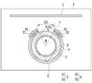
도 1은 본 발명의 일 실시예에 따른 마그네트론 증착 장치의 구성도이다.
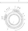
도 2는 도 1에 적용되는 캐소드 타겟과 자기 회로의 사시도이다.
도 3은 요크가 반시계 방향으로 회전하는 작동 상태도이다.
도 4는 요크가 시계 방향으로 회전하는 작동 상태도이다.1 is a configuration diagram of a magnetron deposition apparatus according to an embodiment of the present invention.
2 is a perspective view of a cathode target and a magnetic circuit applied to Fig.
3 is an operating state in which the yoke is rotated counterclockwise.
4 is an operating state in which the yoke is rotated clockwise.
이하, 첨부한 도면을 참조하여 본 발명의 실시예에 대하여 본 발명이 속하는 기술 분야에서 통상의 지식을 가진 자가 용이하게 실시할 수 있도록 상세히 설명한다. 그러나 본 발명은 여러 가지 상이한 형태로 구현될 수 있으며, 여기에서 설명하는 실시예에 한정되지 않는다. 도면에서 본 발명을 명확하게 설명하기 위해서 설명과 관계없는 부분을 생략하였으며, 명세서 전체를 통하여 동일 또는 유사한 구성요소에 대해서는 동일한 참조부호를 붙였다.Hereinafter, embodiments of the present invention will be described in detail with reference to the accompanying drawings so that those skilled in the art can easily carry out the present invention. The present invention may, however, be embodied in many different forms and should not be construed as limited to the embodiments set forth herein. In order to clearly illustrate the present invention, parts not related to the description are omitted, and the same or similar components are denoted by the same reference numerals throughout the specification.
도 1은 본 발명의 일 실시예에 따른 마그네트론 증착 장치의 구성도이다. 도 1을 참조하면, 일 실시예의 마그네트론 증착 장치는 증착 대상인 기판(1)을 설치 수용하고 내부에 진공을 형성하는 진공 챔버(2), 진공 챔버(2) 내에서 백킹 플레이트(3)의 외면에 구비되어 회전하는 캐소드 타겟(4), 캐소드 타겟(4)의 외주에 구비되는 자기 회로(5) 및 요크(6)를 포함한다.1 is a configuration diagram of a magnetron deposition apparatus according to an embodiment of the present invention. Referring to FIG. 1, a magnetron deposition apparatus according to an embodiment includes a
캐소드 타겟(4)은 기판(1)에 박막을 형성하는 모재로써 아르곤(Ar) 이온(플러스 이온)을 끌어당겨서 아르곤 이온이 충돌하도록 파워에 연결된다. 예를 들면, 캐소드 타겟(4)은 음 전위로 연결되고, 진공 챔버(2)는 양 전위로 그라운드 될 수 있다.The
따라서 캐소드 타겟(4)과 진공 챔버(2) 사이에 설정되는 전위차에 의하여, 캐소드 타겟(4)에서 제거된 물질이 포함된 플라즈마가 생성된다. 플라즈마에서 타겟 물질이 튀어나가서 기판(1)에 증착된다.Therefore, by the potential difference set between the
도 2는 도 1에 적용되는 캐소드 타겟과 자기 회로의 사시도이다. 도 1 및 도 2를 참조하면, 자기 회로(5)는 캐소드 타겟(4)의 외주에 제1간격(G1)으로 이격 설치되어, 캐소드 타겟(4)에서 제거된 물질이 포함된 플라즈마로부터 타겟 물질이 튀어나가는 개구(7)를 형성한다.2 is a perspective view of a cathode target and a magnetic circuit applied to Fig. 1 and 2, the
예를 들면, 자기 회로(5)는 개구(7)에서 서로 마주하여 제2간격(G2)으로 이격 배치되어, 캐소드 타겟(4)에 대한 이온 충격(ion bombardment)을 제어하는 제1자석(51)과 제2자석(52)을 포함한다.For example, the
제1, 제2자석(51, 52)은 영구자석으로 형성되고, 개구(7)의 제2간격(G2)을 유지하면서 캐소드 타겟(4)의 길이 방향으로 신장되어 배치된다. 따라서 제1, 제2자석(51, 52)은 개구(7)에서 이온 충격을 제어하면서 캐소드 타겟(4)에서 제거된 물질이 포함된 플라즈마의 밀도를 높인다.The first and
기판(1)에 박막을 형성할 때, 캐소드 타겟(4)은 일정 속도로 회전하고, 자기 회로(5)는 반시계 방향 및 시계 방향으로 번갈아 회전한다. 이를 위하여, 타겟 구동 모터(41)가 캐소드 타겟(4)에 연결되고, 요크 와블링 모터(61)가 요크(6)에 연결된다.When the thin film is formed on the
도 2는 타겟 구동 모터(41)와 요크 와블링 모터(61)가 설치되는 일례를 도시한 것이다. 도시하지 않았으나 캐소드 타겟과 요크는 다양한 동력 전달 구조로 구동될 수 있다.Fig. 2 shows an example in which a
일 실시예의 마그네트론 증착 장치는 타겟 구동 모터(41)를 작동시켜 캐소드 타겟(4)을 일정 속도로 회전시키면서, 요크 와블링 모터(61)를 작동시켜 요크(6) 및 자기 회로(5)를 반시계 및 시계 방향으로 흔든다.The magnetron deposition apparatus of one embodiment activates the
요크(6)는 캐소드 타겟(4)의 외주에 이격 설치되어 자기 회로(5)를 지지한다. 따라서 요크(6)는 캐소드 타겟(4)의 회전을 방해하지 않는다. 즉 제1, 제2자석(51, 52)은 캐소드 타겟(4)에 제1간격(G1)을 유지하고, 서로 제2간격(G2)을 유지하는 상태로 요크(6)에 고정된다.The
따라서 캐소드 타겟(4)이 일정 속도로 회전하는 작동과 별도로 요크(6)가 작동되어 제1, 제2자석(51, 52)을 반시계 및 시계 방향으로 흔든다. 즉 자기 회로(5)에 의하여 설정되는 개구(7)는 기판(1)에 대하여 흔들리면서 캐소드 타겟(4)에서 제거된 타겟 물질을 튀어나가게 한다.Therefore, the
제1, 제2자석(51, 52)으로 설정되는 개구(7)의 각도(θ)는 60~120도로 설정될 수 있다. 진공 챔버(2)가 그라운드 되고 캐소드 타겟(4)에 파워 인가시, 개구(7)에서 캐소드 타겟(4)의 직경 방향으로 전기장이 형성되고, 제1, 제2자석(51, 52) 사이에서 자기장이 형성된다.The angle? Of the opening 7 set by the first and
개구(7)의 각도(θ)가 60도 미만이면 타겟 물질이 포함된 플라즈마의 발생 부위가 너무 좁기 때문에 캐소드 타겟(4)에서 제거된 물질이 포함된 플라즈마에서 튀어나가는 타겟 물질의 양이 너무 적어질 수 있다. 그리고 개구(7)의 각도(θ)가 120도를 초과하면 타겟 물질이 포함된 플라즈마의 발생 부위가 너무 넓기 때문에 개구(7)에 형성되는 전기장에 수직인 자기장의 성분이 감소할 수 있다.If the angle of the
개구(7)의 각도(θ)가 60~120도인 경우, 플라즈마에서 튀어나가는 타겟 물질의 양이 충분하고, 전기장에 수직인 자기장의 성분이 최대화 될 수 있다. 따라서 캐소드 타겟(4)에서 제거된 타겟 물질이 개구(7)를 통하여 튀어나가는 방향에 대한 플라즈마의 밀도가 높아진다.When the
또한 일 실시예의 마그네트론 증착 장치는 자기 회로(5)의 외주, 즉 플라즈마의 주위에 그라운드 쉴드(9)를 더 구비하여, 캐소드 타겟(4)에서 제거된 물질이 자기 회로(5)에 성막되는 것을 방지할 수 있다. 즉 그라운드 쉴드(9)는 자기 회로(5)를 덮는다.The magnetron deposition apparatus of one embodiment further includes a
예를 들면, 그라운드 쉴드(9)는 제1자석(51)을 덮고 요크(6)의 일측에 고정되는 제1쉴드 부재(91), 및 제2자석(52)을 덮고 요크(6)의 다른 일측에 고정되는 제2쉴드 부재(92)를 포함한다. 이 경우, 개구(7)는 제1, 제2쉴드 부재(91, 92) 사이 간격으로 설정될 수 있다.For example, the
제1, 제2쉴드 부재(91, 92)가 구비되는 경우, 캐소드 타겟(4)의 개구(7)에 생성되는 플라즈마에서 튀어나가던 타겟 물질 중 제1, 제2자석(51, 52)으로 되돌아오던 일부는 제1, 제2쉴드 부재(91, 92)에 부착된다. 따라서 제1, 제2자석(51, 52)은 타겟 물질에 의한 성막으로부터 보호될 수 있다.When the first and
캐소드 타겟(4)은 내측에 구비되는 백킹 플레이트(3)의 외주에 구비된다. 따라서 백킹 플레이트(3) 내부에 냉각수(C)가 공급되어 캐소드 타겟(4)의 과열을 방지할 수 있다.The
자기 회로(5)가 캐소드 타겟(4)의 외주에 설치되므로 백킹 플레이트(3) 내에 냉각수(C)를 공급하는 구조가 단순해질 수 있다. 또한, 제1, 제2자석(51)이 캐소드 타겟(4)의 외주에 설치되므로 자기장의 세기 조절이 쉬어진다.Since the
도시하지는 않았으나, 제1, 제2자석의 외주에 자석 조각을 더 붙여서 자기장의 세기를 강하게 하거나, 제1, 제2자석의 외주에 스테인레스 스틸 조각을 더 붙여서 자기장의 세기를 약하게 할 수도 있다.Although not shown, it is also possible to attach a piece of magnet to the outer periphery of the first and second magnets to strengthen the strength of the magnetic field, or to attach a piece of stainless steel to the outer periphery of the first and second magnets to weaken the strength of the magnetic field.
도 3은 요크가 반시계 방향으로 회전하는 작동 상태도이고, 도 4는 요크가 시계 방향으로 회전하는 작동 상태도이다. 도 3 및 도 4를 참조하면, 일 실시예의 마그네트론 증착 장치는 타겟 구동 모터(41)를 작동시켜 캐소드 타겟(4)을 일정 속도로 회전시키면서, 요크 와블링 모터(61)를 작동시켜 제1, 제2자석(51, 52)을 반시계 및 시계 방향으로 흔든다.Fig. 3 is an operating state in which the yoke rotates in a counterclockwise direction, and Fig. 4 is an operating state in which the yoke rotates in a clockwise direction. 3 and 4, the apparatus for magnetron deposition according to an embodiment operates the
이때, 캐소드 타겟(4)에는 파워(음 전위)가 연결되고, 진공 챔버(2)는 그라운드 된다(양 전위). 따라서 아르곤 이온이 개구(7)를 통하여 캐소드 타겟(4)에 충돌되고, 이에 따라 캐소드 타겟(4)에서 제거된 물질이 포함된 플라즈마(P)가 생성된다.At this time, power (negative potential) is connected to the
이때, 플라즈마(P)에서 튀어나오는 타겟 물질은 캐소드 타겟(4)의 회전과 별도로 제1, 제2자석(51, 52)으로 설정되는 개구(7)의 방향이 전환됨에 따라 개구(7)를 통하여 기판(1)에 증착된다.At this time, the target material protruding from the plasma (P) is separated from the opening of the opening (7) as the direction of the opening (7) set by the first and second magnets (51, 52) And is then deposited on the
일 실시예의 마그네트론 증착 장치는 기판(1)에 대한 개구(7)의 방향 전환을 요크(6)의 회전으로 구현하므로 구동 요소를 최소로 적용하면서 기판(1)에서 성막의 균일성을 확보할 수 있다.The magnetron deposition apparatus of one embodiment realizes the switching of the direction of the
이상을 통해 본 발명의 바람직한 실시예에 대하여 설명하였지만, 본 발명은 이에 한정되는 것이 아니고 특허청구범위와 발명의 상세한 설명 및 첨부한 도면의 범위 안에서 여러 가지로 변형하여 실시하는 것이 가능하고 이 또한 본 발명의 범위에 속하는 것은 당연하다.While the present invention has been particularly shown and described with reference to exemplary embodiments thereof, it is to be understood that the invention is not limited to the disclosed exemplary embodiments, but, on the contrary, And it goes without saying that the invention belongs to the scope of the invention.
1: 기판2: 진공 챔버
3: 백킹 플레이트4: 캐소드 타겟
5: 자기 회로6: 요크
7: 개구9: 그라운드 쉴드
41: 타겟 구동 모터51, 52: 제1, 제2자석
61: 요크 와블링 모터91, 92: 제1, 제2쉴드 부재
C: 냉각수G1: 제1간격 G2: 제2간격
P: 플라즈마θ: 개구의 각도1: substrate 2: vacuum chamber
3: backing plate 4: cathode target
5: magnetic circuit 6: yoke
7: aperture 9: ground shield
41: target drive
61: yoke and
C: cooling water G1: first gap G2: second gap
P: Plasma?: Angle of opening
Claims (8)
Translated fromKorean상기 진공 챔버 내에서 백킹 플레이트의 외면에 구비되어 회전하는 캐소드 타겟;
상기 캐소드 타겟의 외주에 이격 설치되어 상기 캐소드 타겟에서 제거된 물질이 포함된 플라즈마에서 타겟 물질이 튀어나가는 개구를 형성하는 자기 회로; 및
상기 캐소드 타겟의 외주에 설치되어 상기 자기 회로를 지지하는 요크
를 포함하는 마그네트론 증착 장치.A vacuum chamber;
A cathode target rotatably provided on an outer surface of the backing plate in the vacuum chamber;
A magnetic circuit spaced apart from the periphery of the cathode target to form an opening through which a target material protrudes from the plasma containing the material removed from the cathode target; And
A yoke for supporting the magnetic circuit,
And a magnetron.
상기 자기 회로는
상기 개구에서 서로 마주하여 이격되는 제1자석과 제2자석
을 포함하는 마그네트론 증착 장치.The method according to claim 1,
The magnetic circuit
A first magnet and a second magnet spaced apart from each other in the opening,
And a magnetron.
상기 제1자석과 상기 제2자석은
상기 개구의 간격을 유지하면서 상기 캐소드 타겟의 길이 방향으로 신장되는 마그네트론 증착 장치.3. The method of claim 2,
The first magnet and the second magnet
And extends in the longitudinal direction of the cathode target while maintaining the spacing of the openings.
상기 캐소드 타겟을 회전하도록 상기 캐소드 타겟에 연결되는 타겟 구동 모터, 및
상기 요크를 정, 역회전하도록 상기 요크에 연결되는 요크 와블링 모터
를 더 포함하는 마그네트론 증착 장치.3. The method of claim 2,
A target drive motor coupled to the cathode target to rotate the cathode target, and
A yoke connected to the yoke for forward and reverse rotation of the yoke,
Further comprising:
상기 백킹 플레이트 내에 냉각수가 공급되는 마그네트론 증착 장치.The method according to claim 1,
And cooling water is supplied into the backing plate.
상기 자기 회로의 외주에 구비되어 상기 자기 회로를 덮는 그라운드 쉴드를 더 포함하는 마그네트론 증착 장치.3. The method of claim 2,
And a ground shield provided on an outer periphery of the magnetic circuit to cover the magnetic circuit.
상기 그라운드 쉴드는
상기 제1자석을 덮고 상기 요크에 고정되는 제1쉴드 부재, 및
상기 제2자석을 덮고 상기 요크에 고정되는 제2쉴드 부재
를 포함하는 마그네트론 증착 장치.The method according to claim 6,
The ground shield
A first shield member covering the first magnet and fixed to the yoke, and
A second shield member covering the second magnet and fixed to the yoke,
And a magnetron.
상기 제1자석과 상기 제2자석으로 설정되는 상기 개구는
60~120도로 설정되는 마그네트론 증착 장치.3. The method of claim 2,
The opening defined by the first magnet and the second magnet
A magnetron deposition apparatus set at 60 to 120 degrees.
Priority Applications (2)
| Application Number | Priority Date | Filing Date | Title |
|---|---|---|---|
| KR1020150007028AKR102245606B1 (en) | 2015-01-14 | 2015-01-14 | Magnetron sputtering apparatus |
| US14/748,648US9558921B2 (en) | 2015-01-14 | 2015-06-24 | Magnetron sputtering apparatus |
Applications Claiming Priority (1)
| Application Number | Priority Date | Filing Date | Title |
|---|---|---|---|
| KR1020150007028AKR102245606B1 (en) | 2015-01-14 | 2015-01-14 | Magnetron sputtering apparatus |
Publications (2)
| Publication Number | Publication Date |
|---|---|
| KR20160087986Atrue KR20160087986A (en) | 2016-07-25 |
| KR102245606B1 KR102245606B1 (en) | 2021-04-28 |
Family
ID=56368023
Family Applications (1)
| Application Number | Title | Priority Date | Filing Date |
|---|---|---|---|
| KR1020150007028AActiveKR102245606B1 (en) | 2015-01-14 | 2015-01-14 | Magnetron sputtering apparatus |
Country Status (2)
| Country | Link |
|---|---|
| US (1) | US9558921B2 (en) |
| KR (1) | KR102245606B1 (en) |
Families Citing this family (2)
| Publication number | Priority date | Publication date | Assignee | Title |
|---|---|---|---|---|
| KR102340351B1 (en) | 2021-05-26 | 2021-12-16 | 고영효 | Magnetic Circuit of Magnetron Sputtering Apparatus and Method of Manufacture Thereof |
| CN119776789B (en)* | 2025-03-12 | 2025-06-10 | 晓睿真空设备(嘉兴)有限公司 | Magnetic yoke assembly on-line swinging device for magnetron sputtering |
Citations (4)
| Publication number | Priority date | Publication date | Assignee | Title |
|---|---|---|---|---|
| US5108574A (en)* | 1991-01-29 | 1992-04-28 | The Boc Group, Inc. | Cylindrical magnetron shield structure |
| JPH06128741A (en)* | 1990-06-08 | 1994-05-10 | Saint Gobain Vitrage Internatl | Rotating cathode |
| KR20050019030A (en)* | 2003-08-08 | 2005-02-28 | 어플라이드 필름즈 게엠베하 & 코. 케이쥐 | Cathodic Sputtering Apparatus |
| KR20120049554A (en)* | 2010-11-09 | 2012-05-17 | 경희대학교 산학협력단 | Rotating cylindrical facing target sputtering system |
Family Cites Families (5)
| Publication number | Priority date | Publication date | Assignee | Title |
|---|---|---|---|---|
| US5262032A (en)* | 1991-05-28 | 1993-11-16 | Leybold Aktiengesellschaft | Sputtering apparatus with rotating target and target cooling |
| KR20010001581A (en) | 1999-06-07 | 2001-01-05 | 윤종용 | Plasma pattern variable sputtering apparatus with rotating magnetic field |
| JP2007092136A (en) | 2005-09-29 | 2007-04-12 | Shin Meiwa Ind Co Ltd | Magnet structure and cathode electrode unit for magnetron sputtering and magnetron sputtering apparatus |
| GB0608582D0 (en) | 2006-05-02 | 2006-06-07 | Univ Sheffield Hallam | High power impulse magnetron sputtering vapour deposition |
| GB0715879D0 (en) | 2007-08-15 | 2007-09-26 | Gencoa Ltd | Low impedance plasma |
- 2015
- 2015-01-14KRKR1020150007028Apatent/KR102245606B1/enactiveActive
- 2015-06-24USUS14/748,648patent/US9558921B2/enactiveActive
Patent Citations (4)
| Publication number | Priority date | Publication date | Assignee | Title |
|---|---|---|---|---|
| JPH06128741A (en)* | 1990-06-08 | 1994-05-10 | Saint Gobain Vitrage Internatl | Rotating cathode |
| US5108574A (en)* | 1991-01-29 | 1992-04-28 | The Boc Group, Inc. | Cylindrical magnetron shield structure |
| KR20050019030A (en)* | 2003-08-08 | 2005-02-28 | 어플라이드 필름즈 게엠베하 & 코. 케이쥐 | Cathodic Sputtering Apparatus |
| KR20120049554A (en)* | 2010-11-09 | 2012-05-17 | 경희대학교 산학협력단 | Rotating cylindrical facing target sputtering system |
Also Published As
| Publication number | Publication date |
|---|---|
| KR102245606B1 (en) | 2021-04-28 |
| US9558921B2 (en) | 2017-01-31 |
| US20160203961A1 (en) | 2016-07-14 |
Similar Documents
| Publication | Publication Date | Title |
|---|---|---|
| JP4491132B2 (en) | Plasma processing equipment | |
| JP2006083408A (en) | Vacuum deposition system | |
| JP2015519477A (en) | Sputtering method for pre-stabilized plasma processing | |
| KR20150123818A (en) | Method of HIPIMS sputtering and HIPIMS sputter system | |
| CN108950499B (en) | Magnetron rotating structure, magnetron assembly and reaction chamber | |
| KR20160087986A (en) | Magnetron sputtering apparatus | |
| EP1211332A1 (en) | Magnetron unit and sputtering device | |
| JP3054441B2 (en) | Apparatus with magnetron sputter coating method and rotating magnet cathode | |
| US20110100799A1 (en) | Sputter deposition system and method | |
| KR102552536B1 (en) | Sputtering apparatus with angle adjustable sputter gun | |
| JP4219566B2 (en) | Sputtering equipment | |
| KR102552593B1 (en) | Angle adjustable sputter gun | |
| CN118136479A (en) | Magnetic control device, magnetron and magnetron sputtering equipment | |
| CN107799375B (en) | A kind of magnetic control element and magnetic control sputtering device | |
| KR101778602B1 (en) | driving means of electrode case for plasma deposition apparatus | |
| WO1999060617A1 (en) | Sputtering apparatus and magnetron unit | |
| KR102664532B1 (en) | Reactive sputter apparatus with enhanced thin film uniformity | |
| TWI576455B (en) | Magnetron source and method of manufacturing | |
| JP2006233240A (en) | Sputtering cathode and sputtering equipment | |
| KR100963413B1 (en) | Magnetron sputtering device | |
| KR102548205B1 (en) | Sputter Gun for sputtering device | |
| KR20190080122A (en) | Reactive sputter apparatus with expanded plasma region | |
| US20090000943A1 (en) | Magnetron sputtering apparatus and manufacturing method for structure of thin film | |
| KR102326673B1 (en) | Driving apparatus for driving sputtering tarket and sputtering apparatus thereof | |
| KR102548201B1 (en) | High-efficiency sputtering device |
Legal Events
| Date | Code | Title | Description |
|---|---|---|---|
| PA0109 | Patent application | Patent event code:PA01091R01D Comment text:Patent Application Patent event date:20150114 | |
| PG1501 | Laying open of application | ||
| A201 | Request for examination | ||
| PA0201 | Request for examination | Patent event code:PA02012R01D Patent event date:20191223 Comment text:Request for Examination of Application Patent event code:PA02011R01I Patent event date:20150114 Comment text:Patent Application | |
| E902 | Notification of reason for refusal | ||
| PE0902 | Notice of grounds for rejection | Comment text:Notification of reason for refusal Patent event date:20210208 Patent event code:PE09021S01D | |
| E701 | Decision to grant or registration of patent right | ||
| PE0701 | Decision of registration | Patent event code:PE07011S01D Comment text:Decision to Grant Registration Patent event date:20210413 | |
| GRNT | Written decision to grant | ||
| PR0701 | Registration of establishment | Comment text:Registration of Establishment Patent event date:20210422 Patent event code:PR07011E01D | |
| PR1002 | Payment of registration fee | Payment date:20210422 End annual number:3 Start annual number:1 | |
| PG1601 | Publication of registration | ||
| PR1001 | Payment of annual fee | Payment date:20240321 Start annual number:4 End annual number:4 |