KR20160087580A - adjustable suture button construct for Anterior Cruciate Ligament reconstruction - Google Patents
adjustable suture button construct for Anterior Cruciate Ligament reconstructionDownload PDFInfo
- Publication number
- KR20160087580A KR20160087580AKR1020150006731AKR20150006731AKR20160087580AKR 20160087580 AKR20160087580 AKR 20160087580AKR 1020150006731 AKR1020150006731 AKR 1020150006731AKR 20150006731 AKR20150006731 AKR 20150006731AKR 20160087580 AKR20160087580 AKR 20160087580A
- Authority
- KR
- South Korea
- Prior art keywords
- ring
- passing
- rope
- hole
- button
- Prior art date
- Legal status (The legal status is an assumption and is not a legal conclusion. Google has not performed a legal analysis and makes no representation as to the accuracy of the status listed.)
- Granted
Links
- 210000001264anterior cruciate ligamentAnatomy0.000titleclaimsabstractdescription15
- 238000004804windingMethods0.000claimsabstractdescription6
- 238000000034methodMethods0.000claimsdescription10
- 238000005452bendingMethods0.000claimsdescription2
- 210000003041ligamentAnatomy0.000description24
- 210000002303tibiaAnatomy0.000description10
- 210000000988bone and boneAnatomy0.000description8
- 210000000689upper legAnatomy0.000description7
- 238000001356surgical procedureMethods0.000description4
- 238000010586diagramMethods0.000description3
- 210000000629knee jointAnatomy0.000description3
- 239000000463materialSubstances0.000description3
- 230000000694effectsEffects0.000description2
- 206010060820Joint injuryDiseases0.000description1
- JVTAAEKCZFNVCJ-REOHCLBHSA-NL-lactic acidChemical compoundC[C@H](O)C(O)=OJVTAAEKCZFNVCJ-REOHCLBHSA-N0.000description1
- 239000004696Poly ether ether ketoneSubstances0.000description1
- RTAQQCXQSZGOHL-UHFFFAOYSA-NTitaniumChemical compound[Ti]RTAQQCXQSZGOHL-UHFFFAOYSA-N0.000description1
- 208000027418Wounds and injuryDiseases0.000description1
- 208000022542ankle injuryDiseases0.000description1
- 230000002917arthritic effectEffects0.000description1
- JUPQTSLXMOCDHR-UHFFFAOYSA-Nbenzene-1,4-diol;bis(4-fluorophenyl)methanoneChemical compoundOC1=CC=C(O)C=C1.C1=CC(F)=CC=C1C(=O)C1=CC=C(F)C=C1JUPQTSLXMOCDHR-UHFFFAOYSA-N0.000description1
- 210000000845cartilageAnatomy0.000description1
- 238000013399early diagnosisMethods0.000description1
- 229920006351engineering plasticPolymers0.000description1
- 239000002657fibrous materialSubstances0.000description1
- 230000007774longtermEffects0.000description1
- 239000002184metalSubstances0.000description1
- 229910052751metalInorganic materials0.000description1
- 239000007769metal materialSubstances0.000description1
- 210000003205muscleAnatomy0.000description1
- 201000008482osteoarthritisDiseases0.000description1
- 229920001432poly(L-lactide)Polymers0.000description1
- 229920002530polyetherether ketonePolymers0.000description1
- 229920001059synthetic polymerPolymers0.000description1
- 229920003002synthetic resinPolymers0.000description1
- 239000000057synthetic resinSubstances0.000description1
- 239000010936titaniumSubstances0.000description1
- 229910052719titaniumInorganic materials0.000description1
Images


Classifications
- A—HUMAN NECESSITIES
- A61—MEDICAL OR VETERINARY SCIENCE; HYGIENE
- A61B—DIAGNOSIS; SURGERY; IDENTIFICATION
- A61B17/00—Surgical instruments, devices or methods
- A61B17/04—Surgical instruments, devices or methods for suturing wounds; Holders or packages for needles or suture materials
- A61B17/0401—Suture anchors, buttons or pledgets, i.e. means for attaching sutures to bone, cartilage or soft tissue; Instruments for applying or removing suture anchors
- A—HUMAN NECESSITIES
- A61—MEDICAL OR VETERINARY SCIENCE; HYGIENE
- A61B—DIAGNOSIS; SURGERY; IDENTIFICATION
- A61B17/00—Surgical instruments, devices or methods
- A61B17/04—Surgical instruments, devices or methods for suturing wounds; Holders or packages for needles or suture materials
- A61B17/06—Needles ; Sutures; Needle-suture combinations; Holders or packages for needles or suture materials
- A61B17/06166—Sutures
- A—HUMAN NECESSITIES
- A61—MEDICAL OR VETERINARY SCIENCE; HYGIENE
- A61F—FILTERS IMPLANTABLE INTO BLOOD VESSELS; PROSTHESES; DEVICES PROVIDING PATENCY TO, OR PREVENTING COLLAPSING OF, TUBULAR STRUCTURES OF THE BODY, e.g. STENTS; ORTHOPAEDIC, NURSING OR CONTRACEPTIVE DEVICES; FOMENTATION; TREATMENT OR PROTECTION OF EYES OR EARS; BANDAGES, DRESSINGS OR ABSORBENT PADS; FIRST-AID KITS
- A61F2/00—Filters implantable into blood vessels; Prostheses, i.e. artificial substitutes or replacements for parts of the body; Appliances for connecting them with the body; Devices providing patency to, or preventing collapsing of, tubular structures of the body, e.g. stents
- A61F2/02—Prostheses implantable into the body
- A61F2/08—Muscles; Tendons; Ligaments
- A61F2/0811—Fixation devices for tendons or ligaments
- A—HUMAN NECESSITIES
- A61—MEDICAL OR VETERINARY SCIENCE; HYGIENE
- A61B—DIAGNOSIS; SURGERY; IDENTIFICATION
- A61B17/00—Surgical instruments, devices or methods
- A61B17/04—Surgical instruments, devices or methods for suturing wounds; Holders or packages for needles or suture materials
- A61B17/0401—Suture anchors, buttons or pledgets, i.e. means for attaching sutures to bone, cartilage or soft tissue; Instruments for applying or removing suture anchors
- A61B2017/0404—Buttons
- A—HUMAN NECESSITIES
- A61—MEDICAL OR VETERINARY SCIENCE; HYGIENE
- A61B—DIAGNOSIS; SURGERY; IDENTIFICATION
- A61B17/00—Surgical instruments, devices or methods
- A61B17/04—Surgical instruments, devices or methods for suturing wounds; Holders or packages for needles or suture materials
- A61B17/0401—Suture anchors, buttons or pledgets, i.e. means for attaching sutures to bone, cartilage or soft tissue; Instruments for applying or removing suture anchors
- A61B2017/0414—Suture anchors, buttons or pledgets, i.e. means for attaching sutures to bone, cartilage or soft tissue; Instruments for applying or removing suture anchors having a suture-receiving opening, e.g. lateral opening
- A—HUMAN NECESSITIES
- A61—MEDICAL OR VETERINARY SCIENCE; HYGIENE
- A61B—DIAGNOSIS; SURGERY; IDENTIFICATION
- A61B17/00—Surgical instruments, devices or methods
- A61B17/04—Surgical instruments, devices or methods for suturing wounds; Holders or packages for needles or suture materials
- A61B17/0401—Suture anchors, buttons or pledgets, i.e. means for attaching sutures to bone, cartilage or soft tissue; Instruments for applying or removing suture anchors
- A61B2017/0464—Suture anchors, buttons or pledgets, i.e. means for attaching sutures to bone, cartilage or soft tissue; Instruments for applying or removing suture anchors for soft tissue
Landscapes
- Health & Medical Sciences (AREA)
- Life Sciences & Earth Sciences (AREA)
- Surgery (AREA)
- Animal Behavior & Ethology (AREA)
- General Health & Medical Sciences (AREA)
- Engineering & Computer Science (AREA)
- Biomedical Technology (AREA)
- Heart & Thoracic Surgery (AREA)
- Veterinary Medicine (AREA)
- Public Health (AREA)
- Rheumatology (AREA)
- Medical Informatics (AREA)
- Molecular Biology (AREA)
- Nuclear Medicine, Radiotherapy & Molecular Imaging (AREA)
- Orthopedic Medicine & Surgery (AREA)
- Rehabilitation Therapy (AREA)
- Cardiology (AREA)
- Oral & Maxillofacial Surgery (AREA)
- Transplantation (AREA)
- Vascular Medicine (AREA)
- Surgical Instruments (AREA)
- Prostheses (AREA)
Abstract
Translated fromKoreanDescription
Translated fromKorean본 발명은 손상된 전방십자인대의 재건을 위한 수술에 사용되는 봉합기구에 관한 것으로써, 더욱 구체적으로는 길이 조절이 가능하면서도 안정적인 고정이 이루어질 수 있으며, 또한 쉽게 늘어나지 않으면서도 강도가 우수한 새로운 형태에 따른 전방십자인대 재건을 위한 수술용 봉합기구에 관한 것이다.The present invention relates to a suturing apparatus used for surgery for reconstructing an injured ACL, and more particularly, to a suture apparatus capable of adjusting a length and stably fixing the suture, To an operative suture instrument for reconstruction of an anterior cruciate ligament.
일반적으로 무릎 관절은 주위의 인대나 근육들에 의해 안전성을 유지하고 있으며, 관절가동범위가 경첩관절(hinge joint)로 자유도가 2가지 방향으로 굴곡과 신전 운동을 하도록 구성되어 있다.In general, the knee joint is maintained by the surrounding ligaments and muscles, and the range of motion of the joint is a hinge joint, which is configured to allow flexion and extension motion in two directions of freedom.
이와 같은 무릎 관절 중 전방십자인대의 경우 상기 무릎관절 속에 위치하면서 대퇴골과 경골을 연결하며 상기 경골이 전방으로 이동하는 것을 막아주고 경골회전을 제한하여 관절 안정성에 기여하는 부위이다.The anterior cruciate ligament of the knee joint is located in the knee joint and connects the femur and the tibia, prevents the tibia from moving forward, and restricts rotation of the tibia, thereby contributing to joint stability.
상기한 전방십자인대는 물체에 부딪히는 외력에 의해 손상되거나, 갑작스러운 방향 전환, 감속동작, 심지어는 헛발질을 할 때 등과 같은 다양한 원인에 의해 파열 등의 상해를 당하는 경우가 있으며, 이렇게 전방십자인대가 파열된 상태에서 치료를 하지 않고 장기간 방치할 경우 관절 연골이 비정상적으로 마모되어 퇴행성관절염이 발생되므로 조기 진단과 치료가 매우 중요하다.The anterior cruciate ligament may be injured by an external force that hits an object, or may be injured by various causes such as a sudden change of direction, decelerating motion, or even an ankle injury, If left untreated for a long time without rupture, arthritic cartilage wears abnormally and degenerative arthritis develops, so early diagnosis and treatment are very important.
상기와 같은 전방십자인대의 손상에 따른 치료가 보존적 치료와 수술적 치료로 나뉘는데, 장기적 관점에서 볼 때 보존적 치료의 경우 장점보다는 단점이 많기 때문에 수술적 치료가 더욱 바람직하다.The treatment of anterior cruciate ligament as described above is divided into conservative treatment and surgical treatment. In the long term, conservative treatment is preferable to surgical treatment because there are many disadvantages rather than merits.
이러한 수술적 치료는 파열된 전방십자인대를 제거한 후 경골과 대퇴골에 골 터널을 형성하여 미리 준비된 이식인대를 파열된 인대와 같은 위치에 놓일 수 있게 상기 골 터널을 통과시킴으로써 수행되며, 이때 상기 이식인대는 봉합용 로프를 연결하여 이 봉합용 로프의 조작을 통해 상기 골 터널을 통과한 이식인대를 봉합 고정하게 되는데, 이를 위한 수술용 봉합기구로써 엔도버튼(endobutton) 기구 혹은, 타이트 로프(tight rope) 기구가 주로 사용되고 있다.This surgical procedure is performed by removing the ruptured anterior cruciate ligament, forming a bone tunnel on the tibia and femur, passing the bone graft through the bone tunnel so that the prepared ligament ligament can be placed in the same position as the ruptured ligament, An endobutton mechanism or a tight rope is used as a surgical suture device for the grafting of the ligament through the bone tunnel through the operation of the suture rope. Appliances are mainly used.
이와 같은 엔도버튼 기구와 타이트 로프 기구에 관련하여는 미국등록특허 US7530990호, 미국등록특허 US8460379호 등에 개시된 바와 같다.Regarding the endo button mechanism and the tight rope mechanism as described above, it is as disclosed in U.S. Patent No. 7530990, U.S.P.
하지만, 전술된 종래 수술용 봉합기구 중 엔도버튼 기구의 경우 인대와 연결한 후에 길이 조절이 불가능하기 때문에 사람 마다의 차이를 맞춰줄 수 없다는 문제점이 있으며, 타이트 로프 기구의 경우는 길이 조절이 가능한 반면 최종 연결하였을 때 전체적인 길이가 일정하게 유지되지 못한다는 연구보고가 있다.However, in the case of the endoprosthesis apparatus of the conventional surgical suture apparatus described above, since the length can not be adjusted after connecting with the ligament, there is a problem that the difference can not be adjusted for each person. In the case of the tightrope mechanism, There is a research report that the overall length can not be kept constant when the final connection is made.
본 발명은 전술된 종래 기술에 따른 각종 문제점을 해결하기 위해 안출된 것으로서, 본 발명의 목적은 길이 조절이 가능하면서도 안정적인 고정이 이루어질 수 있으며, 또한 쉽게 늘어나지 않으면서도 강도가 우수한 새로운 형태에 따른 전방십자인대 재건을 위한 수술용 봉합기구를 제공하는데 있다.SUMMARY OF THE INVENTION The present invention has been made in order to solve various problems of the prior art described above, and it is an object of the present invention to provide a method of fixing a front cross, which is capable of adjusting a length and can be stably fixed, And to provide a surgical suture apparatus for reconstructing ligaments.
상기한 목적을 달성하기 위한 본 발명의 전방십자인대 재건을 위한 수술용 봉합기구는 제1통과홀 및 제2통과홀이 각각 형성되어 이루어진 버튼부; 단일의 로프로 이루어지며, 상기 버튼부의 각 통과홀을 교대로 통과하면서 복수의 교차 및 권취되는 부위를 갖도록 연장되는 로프부;를 포함하여 이루어지며, 상기 로프부는 상기 제1통과홀을 반복 관통하여 버튼부의 일측에 형성되는 제1고리단과, 상기 제1고리단을 형성한 후 상기 제2통과홀을 반복 관통함과 더불어 상기 제1고리단을 추가로 통과함으로써 버튼부의 일측에 형성되는 제2고리단과, 상기 각 고리단의 형성시 상기 버튼부의 타측에 추가로 형성되는 매듭단을 포함하여 이루어짐을 특징으로 한다.In order to accomplish the above object, the surgical suture apparatus for reconstructing anterior cruciate ligament of the present invention comprises: a button portion formed with a first through hole and a second through hole; And a rope portion made of a single rope and extending so as to have a plurality of intersecting and winding portions passing alternately through the respective passing holes of the button portion, wherein the rope portion repeatedly passes through the first passing hole A first ring member formed on one side of the button portion, and a second ring member formed repeatedly through the second passage hole after forming the first ring member and further passing through the first ring member, And a knot that is formed on the other side of the button portion when each of the ring ends is formed.
여기서, 상기 로프부의 매듭단은 상기 로프부의 어느 한 끝단과 다른 한 끝단을 평행하게 위치시킨 상태에서 상기 로프부의 어느 한 끝단을 휘어서 원형의 1차고리가 형성되도록 한 후 상기 평행하게 위치된 부위를 휘감아 상기 1차고리에 통과시키고, 상기 1차고리를 통과시킨 다음에는 제2통과홀을 통과시켜 상기 제2고리단이 형성되도록 한 후 다시금 제2통과홀을 역으로 통과시킴과 더불어 상기 1차고리의 최초 통과 방향과 동일한 방향으로 상기 1차고리를 재차 통과시킴으로써 이루어진 것임을 특징으로 한다.Here, the knot of the rope portion may be formed by bending one end of the rope portion in a state where one end of the rope portion and the other end of the rope portion are positioned in parallel to form a circular first-order rigid portion, Passing through the first ring, passing through the first ring, passing through the second ring hole to form the ring ring, and then passing the ring through the second ring hole again, And passing the primary ring again in the same direction as the initial passing direction.
또한, 상기 로프부의 양 끝단은 상기 매듭단의 후단측 부위에서 추가로 결속되도록 구성함을 특징으로 한다.Further, both ends of the rope portion are further coupled at a rear end side portion of the knot end.
이상에서와 같은 본 발명에 따른 전방십자인대 재건을 위한 수술용 봉합기구는 각 고리단 및 매듭단으로 이루어지는 로프부의 매듭 구조에 의해 이식인대의 추가적인 당김이 가능하여 해당 이식인대가 정확한 위치에 안정적으로 고정될 수 있게 되고, 길이 조정이 완료된 후 당김력을 해재하더라도 매듭단에 의해 풀림이 방지되고 매듭단 후단측에 추가 결속을 함으로써 더욱 안정적이고 단단한 고정 상태로의 유지가 가능하게 된 효과를 가진다.As described above, the surgical suture apparatus for anterior cruciate ligament reconstruction according to the present invention is capable of pulling an additional ligament by the knot structure of the rope portion formed by each of the loop ends and the knotted ends, And even when the pulling force is released after the length adjustment is completed, loosening is prevented by the knot edge, and additional binding is made on the rear end side of the knot edge, so that it is possible to hold the knot in a more stable and firmly fixed state.
특히, 본 발명에 따른 전방십자인대 재건을 위한 수술용 봉합기구는 두 가닥으로 형성한 각 고리단의 구조로 인해 이식인대의 지지를 위한 강도가 더욱 증가될 수 있게 된 효과를 가진다.In particular, the surgical suture apparatus for reconstructing an anterior cruciate ligament according to the present invention has an effect that the strength for supporting the transplant ligament can be further increased due to the structure of each of the two ends of the loop.
도 1은 본 발명의 실시예에 따른 전방십자인대 재건을 위한 수술용 봉합기구를 설명하기 위해 나타낸 상태도
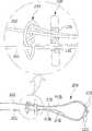
도 2 내지 도 7은 본 발명의 실시예에 따른 전방십자인대 재건을 위한 수술용 봉합기구의 형성을 위한 매듭 과정을 설명하기 위해 순서대로 나타낸 상태도
도 8은 본 발명의 실시예에 따른 전방십자인대 재건을 위한 수술용 봉합기구의 결속단이 추가로 형성된 상태를 설명하기 위해 나타낸 상태도FIG. 1 is a state diagram illustrating a surgical suture apparatus for reconstructing an ACL in accordance with an embodiment of the present invention.
FIGS. 2 to 7 are diagrams illustrating a knotting process for forming an operative suture instrument for reconstructing an anterior cruciate ligament according to an embodiment of the present invention,
8 is a state diagram for explaining a state in which a binding end of a surgical suture instrument for reconstructing an ACL is additionally formed according to an embodiment of the present invention.
이하, 본 발명의 전방십자인대 재건을 위한 수술용 봉합기구에 대한 바람직한 실시예를 첨부된 도 1 내지 도 8을 참조하여 설명하도록 한다.DESCRIPTION OF THE PREFERRED EMBODIMENTS Hereinafter, preferred embodiments of a surgical suturing apparatus for reconstructing an ACL of the present invention will be described with reference to FIGS. 1 to 8.
실시예의 설명에 앞서, 본 발명의 전방십자인대 재건을 위한 수술용 봉합기구는 경골과 대퇴골에 형성되는 골 터널에 이식인대를 고정 설치하기 위한 보조 기구이며, 이때 상기 경골과 대퇴골 및 골 터널에 대한 형상에 대하여는 미국등록특허 US8460379호에 개시된 바와 동일하기 때문에 해당 도면을 참조하기로 하며, 본 발명의 실시예에서는 그에 관련한 구체적인 도시는 생략하도록 한다.Prior to the description of the embodiment, the surgical suture apparatus for reconstructing an anterior cruciate ligament of the present invention is an auxiliary instrument for fixing the ligament graft to the bone tunnel formed on the tibia and the femur, wherein the tibia, Since the shape is the same as that disclosed in U.S. Patent No. US8460379, the drawings will be referred to, and specific illustrations related thereto will be omitted in the embodiment of the present invention.
또한, 설명의 편의상 방향에 대한 설명은 각 도면에 도시된 방향을 기준으로 하며, 이때 도면상 우측 부위는 선단측이라 함과 더불어 도면상 좌측 부위는 후단측이라 한다.For the sake of convenience of explanation, the directions are based on the directions shown in the drawings, and the right side in the drawing is referred to as the front side, and the left side in the drawing is referred to as the rear side.
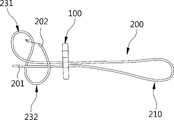
첨부된 도 1은 본 발명의 실시예에 따른 전방십자인대 재건을 위한 수술용 봉합기구를 설명하기 위해 나타낸 상태도이다.BRIEF DESCRIPTION OF THE DRAWINGS The accompanying drawings, which are incorporated in and constitute a part of the specification, illustrate embodiments of the invention and, together with the description, serve to explain the principles of the invention.
이러한 도면을 토대로 알 수 있듯이, 본 발명의 실시예에 따른 전방십자인대 재건을 위한 수술용 봉합기구(이하, “봉합기구”라 함)는 크게 버튼부(100)와, 로프부(200)를 포함하여 이루어지며, 특히 본 발명의 실시예에서는 상기 봉합기구의 로프부(200)가 복수의 교차 및 권취 부위를 갖게 연장되도록 하여 길이 조절이 가능하면서도 안정적인 고정 상태로의 유지가 가능하며, 또한 쉽게 늘어나지 않으면서도 강도가 우수하도록 함을 특징으로 제시한다.As can be seen from these drawings, a surgical suture mechanism (hereinafter referred to as a "suturing mechanism") for reconstructing an ACL in accordance with an embodiment of the present invention comprises a
이를 각 구성별로 더욱 상세히 설명하면 다음과 같다.This will be described in more detail below for each configuration.
먼저, 상기 버튼부(100)는 후술될 로프부(200)의 상태를 유지하기 위한 역할을 수행함과 더불어 경골과 대퇴골에 형성되는 골 터널(도시는 생략됨)에 걸려 고정되는 부위이다.First, the
이와 같은 버튼부(100)는 직육면체와 같은 블럭체로 형성되며, 특히 상기 버튼부(100)는 경골과 대퇴골에 형성되는 골 터널에 비해서는 더욱 면적이 큰 구조물로 형성된다.The
이와 함께, 상기 버튼부(100)에는 서로 이격되게 위치되면서 전후를 관통하는 두 통과홀(110,120)이 각각 형성된다. 이때 상기 각 통과홀(110,120)은 후술될 로프부(200)의 통과를 위한 부위로 사용되나, 해당 버튼부(100)의 조작을 위한 또 다른 봉합사 등의 로프(도시는 생략됨)를 연결하기 위한 부위로도 사용될 수 있다.In addition, the
또한, 상기한 버튼부(100)의 경우 인체에 이식인대와 함께 이식된 상태로 존재함을 고려할 때 그의 재질은 티타늄과 같은 금속이나, PEEK와 같은 엔지니어링 플라스틱 혹은, PLLA와 같은 합성고분자 등의 인체 부작응이 없으면서도 단단한 재질로 형성된다.Considering that the
다음으로, 상기 로프부(200)는 이식인대의 이식 완료시 해당 이식인대가 그 설치 상태로의 유지를 위한 봉합용의 부위이다.Next, the
상기 로프부(200)는 섬유 재질이나 합성수지 재질 혹은, 인체에 무해한 금속 재질로 이루어진다.The
이와 함께, 상기한 로프부(200)는 단일의 로프로 이루어지면서 상기 버튼부(100)의 각 통과홀(110,120)을 교대로 통과하면서 복수의 교차 및 권취 부위를 갖도록 연장 형성된다.In addition, the
특히, 본 발명의 실시예에서는 상기한 로프부(200)가 제1고리단(210) 및 제2고리단(220)과 매듭단(230)을 포함하여 이루어짐을 특징으로 제시하며, 이러한 각 고리단(210,220) 및 매듭단(230)의 구조에 의해 길이 조절이 가능하면서도 이식인대의 더욱 견고한 봉합 고정이 이루어질 수 있도록 한다.Particularly, in the embodiment of the present invention, the
이를 더욱 구체적으로 설명하도록 한다.This will be explained in more detail.
우선, 상기 로프부(200)를 이루는 제1고리단(210) 및 제2고리단(220)은 서로 협력하면서 이식인대에 연결되어 상기 이식인대를 당겨 고정되도록 하는 부위이다.The
여기서, 상기 제1고리단(210)은 상기 버튼부(100)에 형성된 제1통과홀(110)을 반복 관통하여 버튼부(100)의 선단측에 고리 형태로 형성되고, 상기 제2고리단(220)은 상기 제1고리단(210)을 형성한 제2단(202)이 버튼부(100)의 제2통과홀(120)을 반복 관통함과 더불어 상기 제1고리단(210)을 추가로 통과함으로써 버튼부(100)의 선단측에 형성된다.The first
특히, 상기 제1고리단(210)은 로프부(200)의 어느 한 끝단(이하, “제1단”이라 함)(201)은 고정 상태로 유지하면서 다른 한 끝단(이하, “제2단”이라 함)(202)을 상기 버튼부(100)의 후단측에서 제1통과홀(110)을 통과시켜 상기 버튼부(100)의 선단측에 놓이도록 한 후 역방향으로 꺽이도록 휘어서 상기 제1통과홀(110)을 다시금 통과시킴에 따라 상기 버튼부(100)의 선단측에 형성되며, 이는 첨부된 도 2에 도시된 바와 같다.In particular, the
이와 함께, 상기 제2고리단(220)은 상기 제1고리단(210)을 형성하여 버튼부(100)의 후단측으로 인출된 로프부(200)의 제2단(202)이 매듭단(230)을 형성하도록 한 후 상기 버튼부(100)의 제2통과홀(120)을 후단측에서 선단측으로 통과시키고, 계속해서 이렇게 통과된 제2단(202)을 제1고리단(210)에 추가로 통과시킨 후 역방향으로 꺽이도록 휘어서 상기 제2통과홀(120)을 다시금 통과하도록 함으로써 상기 버튼부(100)의 선단측에 형성되며, 이는 첨부된 도 4 및 도 5에 도시된 바와 같다.The
또한, 상기 매듭단(230)은 상기 각 고리단(210,220)의 형성시 상기 버튼부(100)의 후단측에 추가로 형성되어 상기 각 고리단(210,220)의 당김 조작을 통한 길이 조절이 가능하도록 하면서도 각 고리단(210,220)의 당김이 완료된 상태에서는 그 당김 방향과는 반대 방향으로 원치않게 풀림이 방지되도록 형성된 매듭 부위이다.Further, the
이와 같은 매듭단(230)은 상기 로프부(200)의 제1고리단(210)을 형성한 제1단(201)이 제2단(202)과 평행하게 위치되도록 한 상태에서 상기 로프부(200)의 어느 한 끝단을 휘어서 원형의 1차고리(231)가 형성되도록 한 후 상기 평행하게 위치된 부위를 휘감는 2차고리(232)를 형성함과 더불어 그 끝단은 상기 1차고리(231)에 통과시키고, 상기 1차고리(231)를 통과시킨 다음에는 제2통과홀(120)을 통과시켜 상기 제2고리단(220)이 형성되도록 한 후 다시금 제2통과홀(120)을 역으로 통과시킴과 더불어 상기 1차고리(231)의 최초 통과 방향과 동일한 방향으로 상기 1차고리(231)를 재차 통과시킴으로써 이루어진 것임을 제시한다.The
즉, 상기한 매듭단(230)을 통해 상기 각 고리단(210,220)의 당김 조작을 통한 길이 조절이 가능하도록 하면서도 각 고리단(210,220)의 당김이 완료된 상태에서는 원치않게 풀림이 방지되도록 한 것이며, 이에 관련하여는 첨부된 도 3 내지 도 6에 도시된 바와 같다.That is, it is possible to adjust the length by pulling the
한편, 본 발명의 실시예에 따른 봉합기구의 각 부위 중 상기 로프부(200)를 이루는 제1단(201) 및 제2단(202)은 매듭단(230)의 후단측 부위에서 추가로 결속되도록 구성함을 추가로 제시한다.The
즉, 로프부(200)에 대한 길이 조절이 완료된 상태에서 상기 제1단(201) 및 제2단(202)의 결속을 통한 결속단(240)의 추가 제공을 통해 매듭단(230)의 원치않는 풀림이 방지될 수 있도록 한 것이다.In other words, when the length adjustment of the
하기에서는, 전술된 본 발명의 실시예에 따른 봉합기구의 형성 과정 및 이렇게 형성된 봉합기구의 사용 과정에 대하여 더욱 상세히 설명하면 다음과 같다.Hereinafter, the process of forming the suture mechanism according to the embodiment of the present invention and the process of using the suture mechanism thus formed will be described in more detail as follows.
먼저, 로프부(200)와 버튼부(100)를 각각 준비한 상태에서 상기 로프부(200)를 상기 버튼부(100)의 각 통과홀(110,120)에 교대로 통과시키면서 제1고리단(210)과 제2고리단(220) 및 매듭단(230)을 각각 형성한다.The
즉, 로프부(200)의 제1단(201)은 고정 상태로 유지하면서 제2단(202)을 상기 버튼부(100)의 후단측(도면상 좌측)에서 제1통과홀(110)을 통과시켜 상기 버튼부(100)의 선단측(도면상 우측)에 놓이도록 한 후 역방향으로 꺽이도록 휘어서 상기 제1통과홀(110)을 다시금 통과시킴에 따라 상기 버튼부(100)의 선단측에 제1고리단(210)이 형성되도록 하고, 상기 제1고리단(210)을 형성하여 버튼부(100)의 후단측으로 인출된 로프부(200)의 제2단(202)을 휘어서 원형의 1차고리(231)가 형성되도록 한 후 상기 평행하게 위치된 부위를 휘감아 상기 1차고리(231)에 통과시킴으로써 매듭단(230)의 일부가 형성하도록 하며, 이후 상기 제2단(202)을 상기 버튼부(100)의 제2통과홀(120)에 통과시킨 다음 제1고리단(210)에 추가로 통과시킴과 더불어 역방향으로 꺽이도록 휘어서 상기 제2통과홀(120)을 다시금 역으로 통과하도록 함으로써 상기 버튼부(100)의 선단측에 제2고리단(220)이 형성되도록 하고, 상기 제2통과홀(120)을 역으로 통과한 제2단(202)을 상기 1차고리(231)의 최초 통과 방향과 동일한 방향으로 상기 1차고리(231)에 재차 통과시킴으로써 매듭단(230)을 완성하는 것이다. 이에 대하여는 첨부된 도 2 내지 도 6에 도시된 바와 같다.That is, while the
그리고, 상기한 과정을 통해 각 고리단(210,220) 및 매듭단(230)의 형성이 완료된 상태에서는 첨부된 도 7에 도시된 바와 같이 두 고리단(210,220)을 서로 반대 방향으로 당김으로써 상기 매듭부(230)가 오므려지도록 하여 해당 매듭부(230)가 고정될 수 있도록 한다.In addition, as shown in FIG. 7, when the ring ends 210 and 220 and the
전술된 각 과정을 통해 첨부된 도 1과 같은 구조의 봉합기구가 완성된다.The suture mechanism having the structure as shown in FIG. 1 is completed through each of the above-described processes.
또한, 상기와 같이 만들어진 봉합기구는 이식인대의 설치 과정에서 해당 이식인대의 어느 한 측을 고정하는 역할을 수행하게 된다.In addition, the suture mechanism constructed as described above plays a role of fixing one side of the transplanted ligament in the process of installing the transplanted ligament.
즉, 상기 봉합기구를 이루는 로프부(200)의 두 고리단(210,220)이 교차되는 부위에 상기 이식인대를 연결함으로써 해당 봉합기구가 상기 이식인대의 어느 한 부위를 고정하게 되며, 이의 상태에서 상기 이식인대의 끝단을 조작하여 경골과 대퇴골에 형성된 각 골 터널을 통과하면서 상기 경골과 대퇴골 사이의 인대 안착 위치에 놓일 수 있도록 한 후 해당 상태를 유지하도록 고정하고, 계속해서 상기 봉합기구의 로프부(200)를 이루는 각 고리단(210) 중 매듭단(230)을 형성하는 가닥측이 아닌 제1단(201) 및 제2단(202)만 조작하여 상기 이식인대가 당겨지도록 조정하며, 이를 통해 해당 이식인대가 정확한 안착 위치에의 유지 및 고정이 이루어지도록 한다.That is, by connecting the graft ligaments to a portion where the two ring ends 210 and 220 of the
이때, 두 가닥으로 이루어진 제1고리단(210) 및 두 가닥으로 이루어진 제2고리단(220) 중 제1단(201) 및 제2단(202)이 아닌 여타 가닥 부위는 매듭단(230)에 의해 고정된 상태로 유지되기 때문에 각 고리단(210,220) 전부를 당기거나 상기 매듭단(230)에 고정되는 가닥을 당기는 것은 로프부(200)의 길이 변화가 이루어지지 않는다.At this time, the
이후, 전술된 과정을 통해 로프부(200)에 대한 길이 조절이 완료되면 해당 로프부(200)의 제1단(201) 및 제2단(202)을 서로 결속하여 결속단(240)을 추가로 형성함으로써 안정적인 고정 상태로의 유지가 이루어질 수 있게 된다.After the adjustment of the length of the
물론, 상기 결속단(240)을 형성하지 않더라도 로프부(200)의 제1단(201) 및 제2단(202)은 매듭단(230)의 매듭 구조에 의해 풀림이 방지될 수 있다.Of course, the
결국, 본 발명에 따른 전방십자인대 재건을 위한 수술용 봉합기구는 각 고리단(210,220) 및 매듭단(230)으로 이루어지는 로프부(200)의 매듭 구조에 의해 이식인대의 추가적인 당김이 가능하여 해당 이식인대가 정확한 위치에 안정적으로 고정될 수 있게 되고, 길이 조정이 완료된 후 당김력을 해재하더라도 매듭단(230)에 의해 풀림이 방지되기 때문에 안정적인 고정 상태로의 유지가 가능하게 된다.As a result, the surgical suture apparatus for anterior cruciate ligament reconstruction according to the present invention is capable of pulling additional ligaments by the knot structure of the
특히, 두 가닥으로 형성한 각 고리단(210,220)의 구조로 인해 이식인대의 지지를 위한 강도가 더욱 증가될 수 있게 되어 전방십자인대의 재건에 매우 유리하다.Particularly, since the structure of each of the annular ends 210 and 220 formed of two strands can increase the strength for supporting the transplant ligament, it is very advantageous for the reconstruction of the anterior cruciate ligament.
100. 버튼부110. 제1통과홀
120. 제2통과홀200. 로프부
201. 제1단202. 제2단
210. 제1고리단220. 제2고리단
230. 매듭단231. 1차고리
232. 2차고리240. 결속단100.
120. Second through
201.
210.
230.
232. Secondary ring 240. Bonding stage
Claims (3)
Translated fromKorean단일의 로프로 이루어지며, 상기 버튼부의 각 통과홀을 교대로 통과하면서 복수의 교차 및 권취되는 부위를 갖도록 연장되는 로프부;를 포함하여 이루어지며,
상기 로프부는
상기 제1통과홀을 반복 관통하여 버튼부의 선단측에 형성되는 제1고리단과,
상기 제1고리단을 형성한 후 상기 제2통과홀을 반복 관통함과 더불어 상기 제1고리단을 추가로 통과함으로써 버튼부의 선단측에 형성되는 제2고리단과,
상기 각 고리단의 형성시 상기 버튼부의 후단측에 추가로 형성되는 매듭단을 포함하여 이루어짐을 특징으로 하는 전방십자인대 재건을 위한 수술용 봉합기구.A button portion formed with a first through hole and a second through hole, respectively;
And a rope portion made of a single rope and extending so as to have a plurality of intersecting and winding portions passing alternately through the respective passing holes of the button portion,
The rope portion
A first loop end which repeatedly passes through the first passage hole and is formed at the tip end side of the button portion,
A second annular end formed at the distal end side of the button portion by further passing through the first annular end and passing through the second through hole after forming the first annular end,
And a knot formed at a rear end side of the button portion when each of the ring ends is formed.
상기 로프부의 매듭단은
상기 로프부의 제1고리단을 형성한 어느 한 끝단이 다른 한 끝단에 평행하도록 위치시킨 상태에서 상기 로프부의 어느 한 끝단을 휘어서 원형의 1차고리가 형성되도록 한 후 상기 평행하게 위치된 부위를 휘감아 상기 1차고리에 통과시키고, 상기 1차고리를 통과시킨 다음에는 제2통과홀을 통과시켜 상기 제2고리단이 형성되도록 한 후 다시금 제2통과홀을 역으로 통과시킴과 더불어 상기 1차고리의 최초 통과 방향과 동일한 방향으로 상기 1차고리에 재차 통과시킴으로써 이루어진 것임을 특징으로 하는 전방십자인대 재건을 위한 수술용 봉합기구.The method according to claim 1,
The knot of the rope portion
A first circular portion is formed by bending one end of the rope portion in a state where one end of the rope portion forming the first end of the rope is positioned so as to be parallel to the other end of the rope portion, Passing through the first ring, passing through the first ring, passing the second ring through the second ring, passing the ring through the second ring again after passing through the ring, passing the ring through the second ring, And then passing the same again in the same direction in the same direction as the passing direction of the anterior cruciate ligament.
상기 로프부의 양 끝단은 상기 매듭단의 후단측 부위에서 추가로 결속되도록 구성함을 특징으로 하는 전방십자인대 재건을 위한 수술용 봉합기구.The method according to claim 1,
Wherein both ends of the rope portion are further joined at a rear end portion of the knot end.
Priority Applications (1)
| Application Number | Priority Date | Filing Date | Title |
|---|---|---|---|
| KR1020150006731AKR101674544B1 (en) | 2015-01-14 | 2015-01-14 | adjustable suture button construct for Anterior Cruciate Ligament reconstruction |
Applications Claiming Priority (1)
| Application Number | Priority Date | Filing Date | Title |
|---|---|---|---|
| KR1020150006731AKR101674544B1 (en) | 2015-01-14 | 2015-01-14 | adjustable suture button construct for Anterior Cruciate Ligament reconstruction |
Publications (2)
| Publication Number | Publication Date |
|---|---|
| KR20160087580Atrue KR20160087580A (en) | 2016-07-22 |
| KR101674544B1 KR101674544B1 (en) | 2016-11-09 |
Family
ID=56681226
Family Applications (1)
| Application Number | Title | Priority Date | Filing Date |
|---|---|---|---|
| KR1020150006731AActiveKR101674544B1 (en) | 2015-01-14 | 2015-01-14 | adjustable suture button construct for Anterior Cruciate Ligament reconstruction |
Country Status (1)
| Country | Link |
|---|---|
| KR (1) | KR101674544B1 (en) |
Cited By (12)
| Publication number | Priority date | Publication date | Assignee | Title |
|---|---|---|---|---|
| CN107753150A (en)* | 2017-12-05 | 2018-03-06 | 运怡(北京)医疗器械有限公司 | One kind overhauls type belt loop fixed plate |
| CN107837131A (en)* | 2017-12-05 | 2018-03-27 | 运怡(北京)医疗器械有限公司 | A kind of belt loop fixed plate |
| WO2019033480A1 (en)* | 2017-08-17 | 2019-02-21 | 北京德益达美医疗科技有限公司 | Dynamic compression ligament reconstruction system |
| WO2019033479A1 (en)* | 2017-08-17 | 2019-02-21 | 北京德益达美医疗科技有限公司 | Ligament reconstruction system having drug-carrying thread loop |
| CN110074897A (en)* | 2019-05-05 | 2019-08-02 | 北京万洁天元医疗器械股份有限公司 | A kind of adjustable soft tissue Suspending fixation system of loop and its Suspending fixation method |
| KR102035651B1 (en) | 2019-03-07 | 2019-10-23 | (주)올소테크 | Surgical instrument for reconstruction of shoulder ligament |
| WO2019231114A1 (en)* | 2018-05-30 | 2019-12-05 | 아주약품(주) | Method for manufacturing suture anchors by using suture, and suture anchors manufactured thereby |
| KR20200027980A (en)* | 2017-07-06 | 2020-03-13 | 엠.디. 크리스티안 앤더슨 | Self-bundling structure device |
| CN112617924A (en)* | 2020-12-31 | 2021-04-09 | 上海傲派医疗科技有限公司 | Medical loop ring and manufacturing method thereof |
| WO2022141779A1 (en)* | 2020-12-31 | 2022-07-07 | 上海傲派医疗科技有限公司 | Loop and manufacturing method therefor |
| KR20220148325A (en)* | 2017-06-05 | 2022-11-04 | 콘메드 코포레이션 | Suture system and related methods for connecting and creating suspension between at least two bodies |
| US12310840B2 (en) | 2018-11-29 | 2025-05-27 | Xiros Limited | Implant assembly and associated methods of manufacturing |
Citations (3)
| Publication number | Priority date | Publication date | Assignee | Title |
|---|---|---|---|---|
| US20100256677A1 (en)* | 2009-03-31 | 2010-10-07 | Arthrex, Inc. | Integrated adjustable button-suture-graft construct with two fixation devices |
| KR20140022905A (en)* | 2011-05-12 | 2014-02-25 | 스미스 앤드 네퓨, 인크. | Tissue graft anchoring |
| KR20140117539A (en)* | 2012-02-01 | 2014-10-07 | 스미스 앤드 네퓨, 인크. | Tissue graft anchoring |
- 2015
- 2015-01-14KRKR1020150006731Apatent/KR101674544B1/enactiveActive
Patent Citations (3)
| Publication number | Priority date | Publication date | Assignee | Title |
|---|---|---|---|---|
| US20100256677A1 (en)* | 2009-03-31 | 2010-10-07 | Arthrex, Inc. | Integrated adjustable button-suture-graft construct with two fixation devices |
| KR20140022905A (en)* | 2011-05-12 | 2014-02-25 | 스미스 앤드 네퓨, 인크. | Tissue graft anchoring |
| KR20140117539A (en)* | 2012-02-01 | 2014-10-07 | 스미스 앤드 네퓨, 인크. | Tissue graft anchoring |
Cited By (17)
| Publication number | Priority date | Publication date | Assignee | Title |
|---|---|---|---|---|
| KR20220148325A (en)* | 2017-06-05 | 2022-11-04 | 콘메드 코포레이션 | Suture system and related methods for connecting and creating suspension between at least two bodies |
| KR20200027980A (en)* | 2017-07-06 | 2020-03-13 | 엠.디. 크리스티안 앤더슨 | Self-bundling structure device |
| WO2019033479A1 (en)* | 2017-08-17 | 2019-02-21 | 北京德益达美医疗科技有限公司 | Ligament reconstruction system having drug-carrying thread loop |
| WO2019033480A1 (en)* | 2017-08-17 | 2019-02-21 | 北京德益达美医疗科技有限公司 | Dynamic compression ligament reconstruction system |
| CN107837131A (en)* | 2017-12-05 | 2018-03-27 | 运怡(北京)医疗器械有限公司 | A kind of belt loop fixed plate |
| CN107837131B (en)* | 2017-12-05 | 2024-04-16 | 运怡(北京)医疗器械有限公司 | Belt loop fixing plate |
| CN107753150B (en)* | 2017-12-05 | 2024-04-09 | 运怡(北京)医疗器械有限公司 | Revision belt loop fixing plate |
| CN107753150A (en)* | 2017-12-05 | 2018-03-06 | 运怡(北京)医疗器械有限公司 | One kind overhauls type belt loop fixed plate |
| KR20190136196A (en)* | 2018-05-30 | 2019-12-10 | 아주약품(주) | Method for manufacturing suture anchors using sutors and their products |
| WO2019231114A1 (en)* | 2018-05-30 | 2019-12-05 | 아주약품(주) | Method for manufacturing suture anchors by using suture, and suture anchors manufactured thereby |
| US11426157B2 (en) | 2018-05-30 | 2022-08-30 | Aju Pharm Co., Ltd. | Method of preparing suture anchor using suture and prepared suture anchor |
| US12310840B2 (en) | 2018-11-29 | 2025-05-27 | Xiros Limited | Implant assembly and associated methods of manufacturing |
| KR102035651B1 (en) | 2019-03-07 | 2019-10-23 | (주)올소테크 | Surgical instrument for reconstruction of shoulder ligament |
| CN110074897A (en)* | 2019-05-05 | 2019-08-02 | 北京万洁天元医疗器械股份有限公司 | A kind of adjustable soft tissue Suspending fixation system of loop and its Suspending fixation method |
| US20230240673A1 (en)* | 2020-12-31 | 2023-08-03 | Shanghai Orthopair Medical Co., Ltd. | Loop and manufacturing method thereof |
| CN112617924A (en)* | 2020-12-31 | 2021-04-09 | 上海傲派医疗科技有限公司 | Medical loop ring and manufacturing method thereof |
| WO2022141779A1 (en)* | 2020-12-31 | 2022-07-07 | 上海傲派医疗科技有限公司 | Loop and manufacturing method therefor |
Also Published As
| Publication number | Publication date |
|---|---|
| KR101674544B1 (en) | 2016-11-09 |
Similar Documents
| Publication | Publication Date | Title |
|---|---|---|
| KR101674544B1 (en) | adjustable suture button construct for Anterior Cruciate Ligament reconstruction | |
| US11896475B2 (en) | Implant having adjustable filament coils | |
| US12232716B2 (en) | Implant having adjustable filament coils | |
| JP6949853B2 (en) | Graft suspension device | |
| US10285801B2 (en) | Adjustable suture-button construct for knotless stabilization of cranial cruciate deficient ligament stifle | |
| US9700403B2 (en) | Suspensory graft fixation with adjustable loop length | |
| US6517578B2 (en) | Graft suspension device | |
| US10881499B2 (en) | Bone tendon constructs and methods of tissue fixation | |
| EP2772193A1 (en) | Hybrid double bundle acl/pcl graft construct with a single graft | |
| JP7425055B2 (en) | Surgical fixation systems and related methods for performing tissue repair | |
| JP2022514097A (en) | Medical fastening device for fastening grafts | |
| JP2017202325A (en) | Device, system and method for delivery of tissue fixation device | |
| JP2022500187A (en) | Backstop loader |
Legal Events
| Date | Code | Title | Description |
|---|---|---|---|
| A201 | Request for examination | ||
| PA0109 | Patent application | Patent event code:PA01091R01D Comment text:Patent Application Patent event date:20150114 | |
| PA0201 | Request for examination | ||
| PG1501 | Laying open of application | ||
| E701 | Decision to grant or registration of patent right | ||
| PE0701 | Decision of registration | Patent event code:PE07011S01D Comment text:Decision to Grant Registration Patent event date:20161031 | |
| GRNT | Written decision to grant | ||
| PR0701 | Registration of establishment | Comment text:Registration of Establishment Patent event date:20161103 Patent event code:PR07011E01D | |
| PR1002 | Payment of registration fee | Payment date:20161104 End annual number:3 Start annual number:1 | |
| PG1601 | Publication of registration | ||
| FPAY | Annual fee payment | Payment date:20190905 Year of fee payment:4 | |
| PR1001 | Payment of annual fee | Payment date:20190905 Start annual number:4 End annual number:4 | |
| PR1001 | Payment of annual fee | Payment date:20201102 Start annual number:5 End annual number:5 | |
| PR1001 | Payment of annual fee | Payment date:20221101 Start annual number:7 End annual number:7 | |
| PR1001 | Payment of annual fee | Payment date:20231031 Start annual number:8 End annual number:8 | |
| PR1001 | Payment of annual fee | Payment date:20241104 Start annual number:9 End annual number:9 |