KR20160082101A - Automotive transmission - Google Patents
Automotive transmissionDownload PDFInfo
- Publication number
- KR20160082101A KR20160082101AKR1020140194460AKR20140194460AKR20160082101AKR 20160082101 AKR20160082101 AKR 20160082101AKR 1020140194460 AKR1020140194460 AKR 1020140194460AKR 20140194460 AKR20140194460 AKR 20140194460AKR 20160082101 AKR20160082101 AKR 20160082101A
- Authority
- KR
- South Korea
- Prior art keywords
- cover portion
- coil
- cover
- shift lever
- fixed unit
- Prior art date
- Legal status (The legal status is an assumption and is not a legal conclusion. Google has not performed a legal analysis and makes no representation as to the accuracy of the status listed.)
- Granted
Links
Images


Classifications
- B—PERFORMING OPERATIONS; TRANSPORTING
- B60—VEHICLES IN GENERAL
- B60K—ARRANGEMENT OR MOUNTING OF PROPULSION UNITS OR OF TRANSMISSIONS IN VEHICLES; ARRANGEMENT OR MOUNTING OF PLURAL DIVERSE PRIME-MOVERS IN VEHICLES; AUXILIARY DRIVES FOR VEHICLES; INSTRUMENTATION OR DASHBOARDS FOR VEHICLES; ARRANGEMENTS IN CONNECTION WITH COOLING, AIR INTAKE, GAS EXHAUST OR FUEL SUPPLY OF PROPULSION UNITS IN VEHICLES
- B60K20/00—Arrangement or mounting of change-speed gearing control devices in vehicles
- B60K20/02—Arrangement or mounting of change-speed gearing control devices in vehicles of initiating means
- F—MECHANICAL ENGINEERING; LIGHTING; HEATING; WEAPONS; BLASTING
- F16—ENGINEERING ELEMENTS AND UNITS; GENERAL MEASURES FOR PRODUCING AND MAINTAINING EFFECTIVE FUNCTIONING OF MACHINES OR INSTALLATIONS; THERMAL INSULATION IN GENERAL
- F16H—GEARING
- F16H59/00—Control inputs to control units of change-speed- or reversing-gearings for conveying rotary motion
- F16H59/02—Selector apparatus
- F16H59/08—Range selector apparatus
- F16H59/10—Range selector apparatus comprising levers
Landscapes
- Engineering & Computer Science (AREA)
- General Engineering & Computer Science (AREA)
- Mechanical Engineering (AREA)
- Chemical & Material Sciences (AREA)
- Combustion & Propulsion (AREA)
- Transportation (AREA)
- Gear-Shifting Mechanisms (AREA)
Abstract
Translated fromKoreanDescription
Translated fromKorean본 발명은 차량용 변속 장치에 관한 것으로서, 보다 상세하게는 운전자가 변속단을 선택할 수 있는 차량용 변속 장치에 관한 것이다.BACKGROUND OF THE
일반적으로, 차량의 변속 장치(Transmission)는 차량의 속도에 따라 엔진의 회전을 일정하게 유지하기 위하여 기어비를 달리하도록 한 것으로서, 운전자는 변속 장치의 기어비를 바꾸기 위하여 변속 장치에 있는 변속 레버(Shift lever)를 조작하게 된다.Generally, a transmission of a vehicle has a gear ratio different in order to keep the rotation of the engine constant in accordance with the speed of the vehicle. In order to change the gear ratio of the transmission, the shift lever .
이때, 운전자는 운전석 옆에 위치하는 변속 레버를 조작하여 변속단을 선택함으로써 기어비를 변화시킬 수 있다.At this time, the driver can change the gear ratio by selecting the speed change stage by operating the shift lever positioned next to the driver's seat.
변속 장치는 수동 변속 장치와 자동 변속 장치로 크게 구분된다.The transmission is broadly divided into a manual transmission and an automatic transmission.
수동 변속 장치는 운전자가 차량의 주행 속도에 맞추어 1단, 2단, 3단, 4단 등의 변속단을 직접 선택하는 변속 장치이고, 자동 변속 장치는 차량의 주행 속도, 엔진 부하, 스로틀 밸브의 개방량 등에 따라 차량의 ECU가 변속단을 자동으로 조절하는 장치이다.The manual transmission is a shift device that directly selects the gear positions of the first, second, third, and fourth stages in accordance with the traveling speed of the vehicle. The automatic transmission includes a traveling speed of the vehicle, an engine load, The ECU of the vehicle automatically adjusts the speed change stage according to the opening amount and the like.
자동 변속 장치는 일반적으로 차량의 주정차 시에 사용되는 P단, 차량의 전진에 사용되는 D단, 차량의 후진에 사용되는 R단 및 엔진의 출력이 구동륜으로 전달되는 것을 차단하는 N단을 포함하는 변속단으로 구성된다.The automatic transmission generally includes a P stage used for driving a vehicle at an emergency, an D stage used for advancing the vehicle, an R stage used for backing the vehicle, and an N stage for blocking the output of the engine from being transmitted to the drive wheel And a speed change stage.
운전자는 변속 레버를 이용하여 각 변속단을 선택할 수 있는데, 변속 레버의 대표적인 종류로는 레버 타입과 다이얼 타입이 있다. 그 외에 각 변속단이 버튼 형식으로 구성된 차종도 있다.The driver can select each gear range using the shift lever. There are two types of shift lever, lever type and dial type. In addition, there are some vehicles with each speed range button type.
일반적인 레버 타입은 P-R-N-D의 순서로 변속단이 일렬 배치되고 레버를 직선 방향으로 이동시켜 각 변속단을 선택할 수 있도록 구성된다. 최근에는 레버 타입으로서, P-R-N-D의 변속단 위치가 고정되어 있지 않고 레버는 운전자의 조작에 따라 제자리에서 틸팅 후 복귀하도록 구성되어 레버의 틸팅 방향에 따라 P-R-N-D가 차례대로 변하는 방식으로 변속단을 선택할 수 있는 변속 장치가 제공되고 있다.A common lever type is configured such that the speed change stages are arranged in the order of P-R-N-D, and the lever is moved in a linear direction to select each gear change stage. In recent years, as the lever type, the position of the gear position of the PRND is not fixed, and the lever is configured to return after being tilted in place in accordance with the operation of the driver, so that the gear position can be selected in such a manner that the PRND changes sequentially in accordance with the tilting direction of the lever A speed change device is provided.
한편, 다이얼 타입은 일정 각도 범위 내에서 회전하는 다이얼의 주변으로 P-R-N-D의 변속단이 위치하고 다이얼의 특정 포인트를 P-R-N-D의 각 변속단에 위치시킴으로써 변속단을 선택할 수 있도록 구성된다.On the other hand, the dial type is configured such that the speed change stage of the P-R-N-D is positioned in the vicinity of the dial rotating within a certain angle range and the shift stage is selected by positioning a specific point of the dial at each speed change stage of the P-R-N-D.
레버 타입 또는 다이얼 타입의 변속 레버가 장착된 변속 장치는, 운전자가 P-R-N-D의 변속단을 선택하는 때에 변속단의 변화 및 변속 레버가 각 변속단에 위치하였음을 인지할 수 있도록 절도감을 촉각적으로 전달한다. 이와 같은 절도감을 구현하기 위해 변속 장치 내에는 디던트(Detent) 장치가 구비된다. 그러나, 종래의 디턴트 장치는 기구적 구성을 이용해 절도감을 구현하므로 복잡한 구조가 요구되었다.The transmission equipped with the lever type or dial type shift lever tactilely transmits the throttle opening so that when the driver selects the transmission side of the PRND, the change of the speed change stage and the shift lever are located at the respective speed change stages do. In order to realize such a thief feeling, a detent device is provided in the transmission. However, a conventional design has required a complicated structure because it realizes a thief feeling using a mechanical structure.
또한, 차량의 안정적인 주행을 위해, D단에서 P단 또는 R단으로 변속단을 변경하는 경우 또는 반대로 P단 또는 R단에서 D단으로 변경하는 것은 차량이 거의 정지된 상태에서만 이루어져야 한다. 이를 위해 종래의 변속 장치는 일정한 조건이 갖추어졌을 때만 위와 같은 변속단 변경을 허용하고 그 외에는 위와 같은 변속이 불가능하도록 변속 레버의 움직임을 막는 별도의 블로킹 장치가 구비된다.Further, in order to stably drive the vehicle, when changing the speed change stage from the D-stage to the P-stage or R-stage, or vice versa, the change from the P-stage or R-stage to the D-stage should be made only in a state where the vehicle is almost stationary. To this end, the conventional transmission is provided with a separate blocking device that allows the change of the speed change stage only when a predetermined condition is satisfied, and prevents the shift lever from being shifted as described above.
본 발명의 이루고자 하는 기술적 과제는 변속 레버의 추력(推力)을 향상시켜서 변속 시 운전자로 하여금 조작감을 향상시킴에 따라 변속 오작동을 예방할 수 있는 차량용 변속 장치를 제공하는 것이다.SUMMARY OF THE INVENTION It is an object of the present invention to provide a vehicular transmission that can improve a driver's feeling of operation during shifting by improving the thrust of a shift lever, thereby preventing a shift malfunction.
또한, 본 발명의 이루고자 하는 다른 기술적 과제는, 변속 장치의 중량을 줄인 차량용 변속 장치를 제공하는 것이다.It is another object of the present invention to provide a transmission for a vehicle that reduces the weight of the transmission.
본 발명의 과제들은 이상에서 언급한 과제로 제한되지 않으며, 언급되지 않은 또 다른 과제들은 아래의 기재로부터 당업자에게 명확하게 이해될 수 있을 것이다.The problems of the present invention are not limited to the above-mentioned problems, and other problems not mentioned can be clearly understood by those skilled in the art from the following description.
상기 과제를 해결하기 위한 본 발명의 실시 예에 따른 차량용 변속 장치는, 하우징, 변속 레버 및 상기 변속 레버를 이동시키거나 상기 운전자가 상기 변속 레버를 조작하는 힘에 반력을 제공하는 리니어 구동 모터를 포함하고, 상기 리니어 구동 모터는, 상기 하우징에 고정 결합되는 고정 유닛; 상기 고정 유닛에 대해 이동 가능하게 설치되며, 적어도 일부가 상기 고정 유닛의 일부와 중첩되는 외벽 및 상기 외벽의 일단으로부터 교차되는 방향으로 연장 형성되는 커버를 포함하는 가변 유닛 및; 상기 고정 유닛과 상기 가변 유닛 중, 어느 하나의 유닛에 마련되는 코일을 포함하고, 상기 커버는, 제1커버부와, 상기 제1커버부 보다 두껍게 형성되는 제2커버부를 포함하며, 상기 가변 유닛이 상기 고정 유닛 쪽으로 더 이상 이동이 제한된 위치까지 이동한 상태에서, 상기 코일은 상기 제1커버부와 일정 간격 이격되는 구성으로 이루어질 수 있다.To achieve the above object, a vehicular transmission according to an embodiment of the present invention includes a housing, a shift lever, and a linear drive motor that moves the shift lever or provides a reaction force to a force that the driver operates the shift lever Wherein the linear driving motor includes: a fixed unit fixedly coupled to the housing; A variable unit movably installed with respect to the fixed unit, the variable unit including an outer wall overlapping at least a part of the fixed unit and a cover extending in a direction intersecting from one end of the outer wall; And a coil provided in any one of the fixed unit and the variable unit, wherein the cover includes a first cover portion and a second cover portion formed thicker than the first cover portion, The coil may be spaced apart from the first cover part by a predetermined distance in a state where the coil is moved to a position where the movement is further restricted to the fixed unit side.
이 경우, 상기 코일과, 상기 제1커버부 사이의 상기 이격된 간격은 1~2mm인 것이 바람직하다.In this case, the distance between the coil and the first cover is preferably 1 to 2 mm.
상기 고정 유닛은 상기 코일이 감긴 보빈을 포함하고, 상기 보빈은, 상기 하우징에 결합되는 베이스 플레이트 및 상기 베이스 플레이트의 일면으로 연장 형성되어 상기 코일이 감기는 코일 실린더를 포함하며, 상기 베이스 플레이트의 이면에는 일면 방향으로 함몰 형성된 복수의 살 빼기 홈이 형성될 수 있다The bobbin includes a base plate coupled to the housing and a coil cylinder extending from one side of the base plate and wound by the coil, A plurality of recessed grooves formed in one surface direction may be formed
또한, 상기 제2커버부는 상기 제1커버부로부터 상기 가변 유닛의 내측을 향해 연장 형성되어 단차를 형성하며, 상기 단차만큼 상기 제1커버부보다 두꺼운 두께를 갖도록 형성될 수 있다.The second cover portion may extend from the first cover portion toward the inside of the variable unit to form a step, and may have a thickness greater than the first cover portion by the step difference.
또한, 상기 제1커버부의 두께는 상기 외벽의 두께보다 두꺼운 두께로 형성될 수 있으며, 상기 제1커버부의 두께와 상기 외벽의 두께는 3 : 1의 비율로 형성되는 것이 바람직하다.The thickness of the first cover part may be greater than the thickness of the outer wall, and the thickness of the first cover part and the thickness of the outer wall may be 3: 1.
또한, 상기 가변 하우징은, S45C, 퍼멀로이(permalloy), 아몰퍼스(amorphous), 방향성 전자강판, 무방향성 전자강판 및 순철 중 적어도 하나로 형성될 수 있다.In addition, the variable housing may be formed of at least one of S45C, permalloy, amorphous, directional electromagnetic steel sheet, non-directional electromagnetic steel sheet and pure iron.
본 발명의 기타 구체적인 사항들은 상세한 설명 및 도면들에 포함되어 있다.Other specific details of the invention are included in the detailed description and drawings.
이상에서와 같이, 본 발명의 실시 예에 따른 차량용 변속 장치에 의하면, 변속 레버의 추력(推力)이 향상됨에 따라 변속 시 운전자로 하여금 향상된 조작감을 제공하게 됨으로써, 변속 오작동이 예방되는 효과가 제공될 수 있다.As described above, according to the vehicular transmission according to the embodiment of the present invention, since the thrust of the shift lever is improved, it is possible to provide an improved operation feeling to the driver at the time of shifting, thereby preventing the shift malfunction .
또한, 변속 장치의 중량을 줄일 수 있는 효과도 제공될 수 있다.In addition, an effect of reducing the weight of the transmission can also be provided.
본 발명에 따른 효과는 이상에서 예시된 내용에 의해 제한되지 않으며, 더욱 다양한 효과들이 본 명세서 내에 포함되어 있다.The effects according to the present invention are not limited by the contents exemplified above, and more various effects are included in the specification.
도 1은 본 발명의 실시 예에 따른 차량용 변속 장치의 사시도.
도 2는 도 1의 측면도.
도 3은 도 2에서 리니어 구동 모터가 드러나도록 도시한 측면도.
도 4는 본 발명의 실시 예에 따른 차량용 변속 장치에 적용되는 리니어 구동 모터 구성을 도시한 사시도.
도 5는 도 4의 분리 사시도.
도 6a 내지 도 6c는 본 발명의 실시 예에 따른 차량용 변속 장치의 변속에 따라 리니어 구동 모터가 작동되는 상태를 순차적으로 도시한 단면 구성도.
도 7은 본 발명의 실시 예에 따른 차량용 변속 장치에서, 리니어 구동 모터의 중량을 줄이도록 살 빼기 된 상태를 도시한 배면도.
도 8은 본 발명의 실시 예에 따른 차량용 변속장치에서, 리니어 구동 모터의 추력을 종래의 VCM과 비교 도시한 그래프.
도 9는 본 발명의 실시 예에 따른 차량용 변속 장치에서, 리니어 구동 모터의 코일 길이가 조정된 상태를 도시한 단면 구성도.
도 10은 본 발명의 실시 예에 따른 차량용 변속 장치에서, 리니어 구동 모터의 코일 길이를 달리 함에 따른 추력 변이량을 도시한 그래프.1 is a perspective view of a vehicular transmission according to an embodiment of the present invention;
Fig. 2 is a side view of Fig. 1; Fig.
Fig. 3 is a side view showing the linear drive motor shown in Fig. 2; Fig.
4 is a perspective view showing a configuration of a linear drive motor applied to a vehicular transmission according to an embodiment of the present invention.
Fig. 5 is an exploded perspective view of Fig. 4; Fig.
6A to 6C are sectional structural views sequentially showing a state in which the linear drive motor is operated according to the shift of the transmission for a vehicle according to the embodiment of the present invention.
7 is a rear view showing a state in which the weight of the linear drive motor is reduced so as to reduce the weight in the vehicular transmission according to the embodiment of the present invention.
8 is a graph showing the thrust of the linear drive motor in comparison with a conventional VCM in the vehicular transmission according to the embodiment of the present invention.
9 is a sectional structural view showing a state in which the coil length of the linear drive motor is adjusted in the vehicular transmission according to the embodiment of the present invention.
FIG. 10 is a graph showing the amount of thrust variation caused by varying the coil length of the linear drive motor in the vehicular transmission according to the embodiment of the present invention. FIG.
본 발명의 이점 및 특징, 그리고 그것들을 달성하는 방법은 첨부되는 도면과 함께 상세하게 후술되어 있는 실시 예들을 참조하면 명확해질 것이다. 그러나 본 발명은 이하에서 개시되는 실시 예들에 한정되는 것이 아니라 서로 다른 다양한 형태로 구현될 수 있으며, 단지 본 실시 예들은 본 발명의 개시가 완전하도록 하고, 본 발명이 속하는 기술분야에서 통상의 지식을 가진 자에게 발명의 범주를 완전하게 알려주기 위해 제공되는 것이며, 본 발명은 청구항의 범주에 의해 정의될 뿐이다. 명세서 전체에 걸쳐 동일 참조 부호는 동일 구성 요소를 지칭한다.BRIEF DESCRIPTION OF THE DRAWINGS The advantages and features of the present invention and the manner of achieving them will become apparent with reference to the embodiments described in detail below with reference to the accompanying drawings. The present invention may, however, be embodied in many different forms and should not be construed as being limited to the embodiments set forth herein. Rather, these embodiments are provided so that this disclosure will be thorough and complete, and will fully convey the concept of the invention to those skilled in the art. Is provided to fully convey the scope of the invention to those skilled in the art, and the invention is only defined by the scope of the claims. Like reference numerals refer to like elements throughout the specification.
또한, 본 명세서에서 기술하는 실시 예들은 본 발명의 이상적인 예시도인 단면도 및/또는 개략도들을 참고하여 설명될 것이다. 따라서, 제조 기술 및/또는 허용 오차 등에 의해 예시도의 형태가 변형될 수 있다. 또한 본 발명에 도시된 각 도면에 있어서 각 구성 요소들은 설명의 편의를 고려하여 다소 확대 또는 축소되어 도시된 것일 수 있다. 명세서 전체에 걸쳐 동일 참조 부호는 동일 구성 요소를 지칭한다.Further, the embodiments described herein will be described with reference to cross-sectional views and / or schematic drawings that are ideal illustrations of the present invention. Thus, the shape of the illustrations may be modified by manufacturing techniques and / or tolerances. In addition, in the drawings of the present invention, each component may be somewhat enlarged or reduced in view of convenience of explanation. Like reference numerals refer to like elements throughout the specification.
이하, 본 발명의 실시 예에 따른 차량용 변속 장치에 대한 바람직한 실시 예를 첨부된 예시도면에 의거하여 상세히 설명한다.Hereinafter, preferred embodiments of a vehicular transmission according to an embodiment of the present invention will be described in detail with reference to the accompanying drawings.
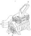
도 1은 본 발명의 실시 예에 따른 차량용 변속 장치의 사시도이고, 도 2는 도 1의 측면도이며, 도 3은 도 2에서 리니어 구동 모터가 드러나도록 도시한 측면도이다.FIG. 1 is a perspective view of a transmission for a vehicle according to an embodiment of the present invention, FIG. 2 is a side view of FIG. 1, and FIG. 3 is a side view illustrating the linear drive motor in FIG.
도시된 바와 같이, 본 발명의 실시 예에 따른 차량용 변속 장치(1)는, 변속 레버(10), 변속 레버(10)의 하부에 위치하여 변속 레버(10)를 둘러싸는 상부 하우징(21), 상부 하우징(21)의 일측 하부 및 타측 하부에 각각 결합되는 제1측부 하우징(22) 및 제2측부 하우징(23)을 포함할 수 있다.As shown in the drawings, the
변속 레버(10) 및 하우징(21,22,23)은 차량 실내의 센터페시아(Center fascia)와 센터콘솔박스 (Center console box)사이에서 실내에 노출되도록 설치되고, 제1측부 하우징(22) 및 제2측부 하우징(23)은 차량의 실내에 노출되지 않고 센터페시아로부터 센터콘솔박스로 이어지는 공간 내에 위치될 수 있다.The
변속 레버(10)는 운전자에 의해 조작되며, 전방 또는 후방으로 이동되면서 P-R-N-D의 순서로 변속단을 선택할 수 있다. 한편, 수동 변속 모드를 지원하는 변속 장치(1)의 경우에는 변속 레버(10)를 좌측 또는 우측으로 이동시키거나 전방 또는 후방으로 이동시킴으로써, 1단, 2단, 3단 4단 등의 변속단을 선택할 수 있다.The
상부 하우징(21)에는 파킹 버튼(P)이 형성될 수 있다. 파킹 버튼은 EPB(Electric Parking Brake)의 작동 버튼일 수 있고, 또는 P단 변속단을 설정하는 버튼일 수도 있는데, 이 경우에는 변속 레버(10)에 의해 선택되는 변속단이 R-N-D의 순서로 이루어질 수 있다.A parking button P may be formed on the
제1측부 하우징(22)과 제2측부 하우징(23) 사이에는 변속 장치(1)의 후방을 형성하는 내부 하우징(24)이 위치될 수 있다. 내부 하우징(24)은 그 내부에 위치하는 리니어 구동 모터(80)의 보빈(850)과 결합될 수 있으며, 이때 내부 하우징(24)은 스크류(S5, S6)에 의해 보빈(850)과 결합될 수 있다.Between the
본 발명의 실시 예에 따른 차량용 변속 장치(1)의 내부 구조는 도 2에 도시된 바와 같다. 즉, 하우징의 내부에는 변속 레버(10)를 지지하는 변속 레버 샤프트(40), 변속 레버 샤프트(40)를 회동 가능하게 지지하는 샤프트 홀더(30), 변속 레버 샤프트(40)에 대하여 상대 회전 가능하게 결합되는 링크 부재(70), 링크 부재(70) 및 내부 하우징(24)에 각각 결합되는 리니어 구동 모터(80)를 포함할 수 있다.The internal structure of the vehicular transmission (1) according to the embodiment of the present invention is as shown in Fig. Inside the housing, there are provided a
여기서, 샤프트 홀더(30)는 하우징(21,22,23) 중, 어느 하나의 하우징에 고정 설치되어, 변속 레버 샤프트(40)가 샤프트 회동축(421)을 중심으로 회동 동작만 가능하도록 규제한다.Here, the
또한, 도 3에 도시된 바와 같이, 본 발명의 실시 예에 따른 차량용 변속 장치(1)는, 앞서 언급한 바와 같이 변속 레버 샤프트(40)와 상대 회전 가능하게 결합되는 링크 부재(70)와, 링크 부재(70)에 일부가 결합되고 내부 하우징(24)에 다른 일부가 결합되는 리니어 구동 모터(80)를 포함한다.3, the
여기서, 리니어 구동 모터(80) 중, 링크 부재(70)와 결합되는 부분을 가변 유닛이라 하고, 내부 하우징(24)에 결합되는 부분을 고정 유닛이라 하기로 한다.Here, a portion of the
링크 부재(70)는 플랜지(71)와 플랜지(71)의 일면으로부터 변속 레버 샤프트(40)의 관통홀을 향해 연장 형성되는 한 쌍의 결합조(72)를 포함할 수 있다.The
플랜지(71)의 이면에는 리니어 구동 모터(80)의 가변 유닛이 설치되고, 가변 유닛과 플랜지(71)는 스크류(S3, S4)에 의해 결합될 수 있다.A variable unit of the
리니어 구동 모터(80)의 고정 유닛은 고정 설치되는 내부 하우징(24)에 결합되고, 가변 유닛은 내부 하우징(24)과 함께 고정되는 고정 유닛으로부터 직선 방향(도 3을 기준으로 좌우방향)으로 일정 간격 범위 내에서 이동 가능하게 설치될 수 있다.The fixed unit of the
따라서, 운전자가 변속 레버(10)를 조작하면, 변속 레버 샤프트(40)는 회동부를 중심으로 회동하게 되고, 그에 따라 링크 부재(70) 및 가변 유닛은 직선 방향으로 이동하게 된다. 반대로, 가변 유닛이 직선 방향으로 이동하게 되면, 링크 부재(70)는 가변 유닛과 함께 직선 방향으로 이동하고, 그에 따라 변속 레버 샤프트(40) 및 변속 레버(10)가 회동하게 된다.Therefore, when the driver operates the
이하에서는, 본 발명의 실시 예에 따른 차량용 변속 장치(1)에 적용되는 리니어 구동 모터(80)에 대하여 설명한다.Hereinafter, the
도 4는 본 발명의 실시 예에 따른 차량용 변속 장치에 적용되는 리니어 구동 모터 구성을 도시한 사시도이고, 도 5는 도 4의 분리 사시도이며, 도 6a 내지 도 6c는 본 발명의 실시 예에 따른 차량용 변속 장치의 변속에 따라 리니어 구동 모터가 작동되는 상태를 순차적으로 도시한 단면 구성도이다.FIG. 4 is a perspective view illustrating a configuration of a linear drive motor applied to a vehicular transmission according to an embodiment of the present invention, FIG. 5 is an exploded perspective view of FIG. 4, And a state in which the linear drive motor is operated in accordance with the shift of the transmission.
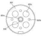
또한, 도 7은 본 발명의 실시 예에 따른 차량용 변속 장치에서, 리니어 구동 모터의 중량을 줄이도록 살 빼기 된 상태를 도시한 배면도.7 is a rear view showing a state in which the weight of the linear drive motor is reduced so as to reduce the weight in the vehicular transmission according to the embodiment of the present invention.
먼저, 도 4 및 도 5에 도시된 바와 같이, 리니어 구동 모터(80)는, 가변 하우징(810), 마그넷(820), 요크(830)를 포함하는 가변 유닛과, 모터 샤프트(840), 보빈(850), 코일(860)을 포함하는 고정 유닛으로 구성될 수 있다.4 and 5, the
본 발명의 실시 예에 적용되는 리니어 구동 모터(80)는 기본적으로 코일(860)에 인가되는 전류의 변화에 의해 형성되는 자기장에 영향을 받아 마그넷(820)이 이동하며 이에 따라 가변 유닛이 고정 유닛에 대하여 직선 방향으로 이동되는 구동 원리를 갖는다.The
모터 샤프트(840)는 리니어 구동 모터(80)의 중심축을 형성하며, 일단은 가변 유닛의 전방으로 노출되고, 타단은 보빈(850)의 베이스 플레이트(851)에 형성되는 모터 샤프트 수용단(851a)에 고정될 수 있다.The
이때, 가변 유닛의 전방으로 노출되는 모터 샤프트(840)의 일단은 링크 부재(70)의 플랜지(71)를 관통할 수 있다.At this time, one end of the
모터 샤프트(840)는 고정 유닛에 대하여 상대 이동하는 가변 유닛 및 링크 부재(70)의 이동 방향을 가이드 할 수 있다.The
보빈(850)은 내부 하우징(24)과 결합되는 베이스 플레이트(851)와, 베이스 플레이트(851)의 일면으로부터 연장 형성되는 코일 실린더(852)를 포함할 수 있다.The
베이스 플레이트(851)의 중심에는, 전술한 바와 같이 모터 샤프트(840)의 타단을 고정하는 모터 샤프트 수용단(851a)이 형성될 수 있는데, 모터 샤프트 수용단(851a)은 모터 샤프트(840)의 타단 일부가 노출되도록 베이스 플레이트(851)의 이면에 돌출 형성될 수 있다.A motor
또한, 베이스 플레이트(851)의 이면에는 내부 하우징(24)과 베이스 플레이트(851)를 고정하는 스크류가 삽입되는 스크류 홀(851b)들이 형성될 수 있다.The
또, 베이스 플레이트(851)의 이면에는, 모터 샤프트 수용단(851a)과 스크류 홀(851b) 사이에 복수의 살 빼기 홈(851c)이 형성될 수 있다. 여기서 복수의 살 빼기 홈(851c)은 베이스 플레이트(851)의 이면과 단차를 두고 일면 방향으로 함몰 형성되거나, 베이스 플레이트(851)의 이면을 관통하도록 형성될 수 있는데, 이러한 복수의 살 빼기 홈(851c)들은 리니어 구동 모터(80)의 경량화를 위하여 형성될 수 있다.(도 7 참조)A plurality of
한편, 도 6a 내지 도 6c에 도시된 바와 같이, 코일 실린더(852)는 베이스 플레이트(851)의 외면과 단차를 형성하여 연장 형성될 수 있으며, 코일 실린더(852)의 외측면에는 코일(860)이 감기게 된다.6A to 6C, the
코일 실린더(852)의 내측에는 빈 공간이 형성되고, 이 빈 공간에 모터 샤프트(840)와, 가변 유닛을 이루는 마그넷(820) 및 요크(830) 등이 수용될 수 있으며, 가변 유닛은 모터 샤프트(840)를 따라 직선 방향으로 이동할 수 있게 되는데, 이에 대한 작동관계는 후에 상세히 설명하기로 한다.A hollow space is formed inside the
가변 유닛을 이루는 가변 하우징(810)은, 대략 통 형상으로 이루어지고, 적어도 일부가 코일(860) 외측을 둘러싸는 외벽(811)과, 이 외벽(811)과 교차되는 방향으로 연장 형성되어 한쪽 개구 부위를 차폐하는 커버(812,813)를 포함할 수 있다.The
여기서 커버는, 제1커버부(812)와 제2커버부(813)로 구분될 수 있다. 이 경우 제1커버부(812)는 외벽(811)과 대략 직각이 되도록 외벽(811)의 일단으로부터 교차되는 방향으로 연장 형성되어 커버의 주변부를 형성하고, 제2커버부(813)는 제1커버부(812)로부터 내측으로 연장 형성되어 커버의 중앙부를 형성할 수 있다. 이때 제2커버부(813)의 직경은 마그넷(820)의 직경과 대응되도록 형성될 수 있다.Here, the cover may be divided into a
특히, 제2커버부(813)는 제1커버부(812) 보다 두꺼운 두께로 형성될 수 있다. 이때 가변 하우징(810)의 일면은 링크 부재(70)의 이면과 결합되므로 제1커버부(812)와 제2커버부(813)의 일면은 동일한 평면을 이루도록 형성되고, 제2커버부(813)의 이면은 제1커버부(812)의 이면과 단차를 형성하여 외벽(811)과 나란한 방향으로 돌출 형성됨으로써 제2커버부(813)는 단차의 두께만큼 제1커버부(812) 보다 두꺼운 두께로 형성될 수 있다.In particular, the
커버는, 마그넷(820)이 자력에 의해 이동하거나 제자리를 유지함에 따라 발생하는 추력을 링크 부재(70)에 직접적으로 전달하게 된다. 추력은 마그넷(820)과 코일(860) 간에 작용하는 자력 외에 커버의 중량과 비례하는 상관 관계를 갖는다.The cover directly transmits the thrust generated as the
그러나, 추력의 향상을 위하여 커버의 직경 또는 두께를 증가시키면 리니어 구동 모터(80)의 전체적인 크기가 커지게 되고 이에 따라 중량도 증가하게 되는 문제가 있다.However, if the diameter or the thickness of the cover is increased to improve the thrust, the overall size of the
따라서, 본 발명의 실시 예에 따른 차량용 변속 장치(1)에 적용되는 리니어 구동 모터(80)는, 마그넷(820)과 직접 맞닿아 마그넷(820)에 의해 발생하는 추력을 직접적으로 전달하는 제2커버부(813)의 두께는 상대적으로 두껍게 형성하여 제2커버부(813)의 중량을 보다 무겁게 가져가 추력을 향상시키는 반면, 제2커버부(813)와 외벽(811)을 연결하는 제1커버부(812)의 두께는 상대적으로 얇게 형성하여 제1커버부(812)의 중량은 보다 가볍게 가져가 리니어 구동 모터(80)의 경량화를 추구할 수 있다.Therefore, the
참고로, 제1커버부(812)에는 링크 부재(70)와 결합되기 위해 사용되는 스크류가 진입하는 스크류 홀(812a)들이 형성될 수 있다.For reference, the
커버의 제2커버부(813)에는 모터 샤프트(840)가 관통하는 제1샤프트 홀(813b)이 형성된다. 이때 제1샤프트 홀(813b)의 내경 일부는 모터 샤프트(840)의 외경보다 크게 형성되어 제1샤프트 홀(813b)과 모터 샤프트(840) 사이에 제1부쉬(871)가 삽입되어 설치될 수 있다.A
제1부쉬(871)는 제1샤프트 홀(813b)과 모터 샤프트(840)의 직접적인 접촉을 방지하고, 가변 하우징(810)이 모터 샤프트(840)를 따라 용이하게 이동할 수 있도록 하는 역할을 수행한다.The
또한, 제2커버부(813)의 이면에는 제1샤프트 홀(813b)을 중심으로 돌출 형성되는 제1조립단(813a)이 형성될 수 있는데, 이 제1조립단(813a)은 후술되는 마그넷(820)의 제2조립단(822)과 끼워 맞춤이 이루어져서 제2커버부(813)와 마그넷(820)의 밀착 조립이 용이하게 이루어지도록 하는 기능을 갖는다.A
이상에서 설명한 가변 하우징(810)은, 마그넷(820)과 코일(860) 사이에 자력이 효과적으로 전달되도록 S45C, 퍼멀로이(Permalloy), 아몰퍼스(Amorphous), 방향성 전자강판, 무방향성 전자강판, 순철 등으로 형성될 수 있다.The
전술한 바와 같이, 제2커버부(813)의 이면에는 마그넷(820)이 밀착되어 배치되는데, 마그넷(820)은 네오디뮴(Neodymium)과 같은 강자력의 자성체가 적용될 수 있다.As described above, the
마그넷(820)은 고정 유닛의 코일(860)에 인가되는 전류 변화에 따라 형성되는 자기장에 반응하여 모터 샤프트(840)를 따라 직선 방향으로 이동하거나 제자리를 유지하게 된다.The
따라서, 마그넷(820)의 중심부에는 모터 샤프트(840)가 관통하는 제2샤프트 홀(821)이 형성된다.Therefore, a
마그넷(820)의 일면에는 제2샤프트 홀(821)을 중심으로 제2커버부(813)의 제1조립단(813a)에 대응하여 함몰 형성되는 제2조립단(822)이 형성될 수 있다. 여기서, 제2커버부(813)의 제1조립단(813a)은 돌출 형성되고 마그넷(820)의 제2조립단(822)은 함몰 형성되는 것을 일 예로 설명하였으나 양자의 암수 관계는 바뀔 수도 있음은 물론이다.A
또한, 마그넷(820)의 이면에는 제2샤프트 홀(821)을 중심으로 제3조립단(도면부호 미부여)이 함몰 형성될 수 있다.In addition, a third assembly stage (not designated) may be formed on the back surface of the
한편, 마그넷(820)의 이면에는 요크(830)가 배치될 수 있으며, 요크(830)는 마그넷(820)과 코일(860) 간에 형성되는 자기장의 자속 분포를 마그넷(820) 및 코일(860)에 대략 수직하게 형성시켜서 불필요한 자속을 최소화하는 기능을 담당한다.A
요크(830)의 중심부에는 모터 샤프트(840)가 관통하는 제3샤프트 홀(831)이 형성되고, 요크(830)의 일면에는 제3샤프트 홀(831)을 중심으로 마그넷(820)의 제3조립단(에 대응하여 돌출 형성되는 제4조립단(832)이 형성될 수 있다. 여기서, 마그넷(820)의 제3조립단은 함몰 형성되고 요크(830)의 제4조립단(831)은 돌출 형성되는 것을 일 예로 설명하였으나 양자의 암수 관계는 바뀔 수도 있다.A
또한, 요크(830)의 이면에는 제3샤프트 홀(831)의 내경 일부가 확장된 부쉬 설치홈(833)이 형성될 수 있는데, 이 부쉬 설치홈(833)에는 제2부쉬(872)가 삽입되어 설치될 수 있다. 즉, 요크(830)의 제3샤프트 홀(831)과 모터 샤프트(840)에 제2부쉬(872)가 개재될 수 있으며, 이러한 제2부쉬(872)는 앞서 설명한 제1부쉬(871)와 유사하게, 요크(830)와 모터 샤프트(840)의 직접적인 접촉을 방지하고, 요크(830)가 모터 샤프트(840)를 따라 용이하게 이동하도록 하는 기능을 제공한다.A
참고로, 본 발명의 실시 예에서는 마그넷(820)이 가변 유닛에 배치되고, 코일(860)은 고정 유닛에 배치되는 것을 일 예로 들어 설명하였으나, 반대로 마그넷(820)이 고정 유닛에 배치되고 코일(860)이 가변 유닛에 배치될 수도 있다.For example, in the embodiment of the present invention, the
한편, 가변 하우징(810)의 제2커버부(813), 마그넷(820) 및 요크(830)는 대략 동일한 직경을 갖도록 형성되어 가변 하우징(810)의 외벽(811)과 일정한 간격을 유지할 수 있다.The
따라서, 가변 하우징(810)의 제2커버부(813), 마그넷(820) 및 요크(830)와, 외벽(811) 사이에는 일정공너비의 공간부(814)가 형성될 수 있으며, 이 공간부(814)에는 코일(860) 및 코일 실린더(852)가 이동 가능하게 위치될 수 있다.A
즉, 코일(860) 및 코일 실린더(852)는 가변 하우징(810), 마그넷(820) 및 요크(830)가 일체화되어 모터 샤프트(840)를 따라 슬라이딩 이동할 때, 공간부(814) 내에서 진퇴를 반복하면서 이동이 이루어질 수 있다.That is, when the
참고로, 공간부(814)의 너비는 가변 하우징(810) 커버 중, 제1커버부(812)의 너비와 동일 또는 유사하게 형성될 수 있다.The width of the
한편, 본 발명의 실시 예에 적용되는 리니어 구동 모터(80)는, 외벽(811)의 두께와 제1커버부(812)의 두께 비율이 대략 1:3이 되도록 형성될 수 있다.Meanwhile, the
앞서 설명한 바와 같이, 제2커버부(813)의 두께(t2)를 상대적으로 두껍게 형성하고, 제1커버부(812)의 두께(t3)를 상대적으로 얇게 형성함에 따라 리니어 구동 모터(80)의 추력을 향상시키면서도 경량화가 가능하게 된다.The thickness t2 of the
또한, 경량화를 위한 최적화된 제1커버부(812)의 두께(t3)를 찾기 위하여 다양한 실험을 실시하였으며, 그 결과 제1커버부(812)의 두께(t3)를 외벽(811)의 두께(t1)의 약 3배가 되도록 형성하는 경우, 최대의 추력을 얻을 수 있음을 확인할 수 있었다.As a result, the thickness t3 of the
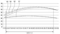
도 8은 본 발명의 실시 예에 따른 차량용 변속 장치에서, 리니어 구동 모터의 추력을 다양한 실험 예와 비교 도시한 그래프이다.8 is a graph showing the thrust of the linear drive motor in comparison with various experimental examples in the vehicular transmission according to the embodiment of the present invention.
도 8에 도시된 그래프 중, G1은 종래 VCM(Voice coil motor)의 추력 추이를 나타내고 있다.In the graph shown in FIG. 8, G1 shows a thrust transition of a conventional VCM (Voice coil motor).
그리고, G2는 본 발명의 실시 예에 따른 차량용 변속 장치(1)에서, 리니어 구동 모터(80)와 동일 또는 유사한 구성으로 제1커버부(812)의 두께(t3)와 외벽(811)의 두께(t1)를 모두 1t로 설계한 경우의 추력 추이를 나타낸 것이다.G2 denotes the thickness t3 of the
그리고, G3는 본 발명의 실시 예에 따른 차량용 변속 장치(1)에서, 리니어 구동 모터(80)와 동일 또는 유사한 구성으로 제1커버부(812)의 두께(t3)를 2t로 설계하고, 외벽(811)의 두께(t2)는 1t로 설계한 경우의 추력 추이를 나타낸 것이다.G3 design the thickness t3 of the
그리고, G4는 본 발명의 실시 예에 따른 차량용 변속 장치(1)에서, 리니어 구동 모터(80)와 동일 또는 유사한 구성으로 제1커버부(812)의 두께(t3)를 3t로 설계하고, 외벽(811)의 두께(t1)를 1t로 설계한 경우의 추력 추이를 나타낸 것이다.G4 designates the thickness t3 of the
참고로, G2, G3 및 G4는 가변 하우징(810)을 S45C로 형성한 리니어 구동 모터(80)를 이용하여 실험을 실시하였다.For reference, G2, G3 and G4 were experimented using a
도시된 바와 같이, 종래의 VCM은 추력이 40N 미만에서 형성되어 차량용 변속 장치(1)에 실제 적용하기 어려움을 확인하였다.(G1 참고)As shown in the figure, the conventional VCM is formed at a thrust of less than 40N, and thus it is difficult to actually apply the VCM to the
예를 들어, 차량의 주행 중에, 운전자가 D단에서 P단 또는 R단으로 변속단을 변경하거나 반대로 P단 또는 R단에서 D단으로 변속단 변경을 시도하는 경우, 차량의 안정적인 주행을 위하여 위와 같은 변속이 이루어지지 않도록 변속 레버(10)의 움직임을 제한하는 반력이 발생되어야 한다.For example, when the driver changes the speed change stage from the D-stage to the P-stage or R-stage, or when the driver attempts to change the speed change stage from the P-stage or R-stage to the D-stage during running of the vehicle, A reaction force to limit the movement of the
이러한 요구를 안정적으로 구현하기 위해서는 VCM의 추력이 최소한 40N 이상으로 출력되어야 하나, 종래의 VCM은 유효 거리 내에서 40N 미만의 추력을 제공할 뿐이어서 차량용 변속 장치(1)에 실제 적용하기 어렵게 된다.In order to stably implement such a demand, the thrust of the VCM should be at least 40N or more, but the conventional VCM is not practical to be applied to the
그리고, G2의 경우에는, 종래의 VCM에 비하여 월등히 향상된 추력 추이를 나타내기는 하지만, 유효 거리 내 일부 구간에서 40N 미만의 추력이 나타남을 확인할 수 있었다.In the case of G2, it is confirmed that a thrust less than 40N appears in a certain section of the effective distance, though the thrust is much improved as compared with the conventional VCM.
그리고, G3 및 G4의 경우에는, 유효 거리 내에서 모두 40N 이상의 추력 추이를 나타내고는 있지만, G4의 경우가 G3에 비하여 짧은 유효거리에서 더 우월한 추력 추이를 나타냄을 확인할 수 있었다.In the case of G3 and G4, it was confirmed that the thrust force of 40 N or more was all within the effective distance, but that of G4 was higher than that of G3 at a shorter effective distance.
특히, G4의 경우에는 유효 거리의 시작 시점부터 45N 이상의 추력을 나타내므로, 본 발명의 일 실시 예에 따른 변속 장치(1)는, 주행 상황에서 특정 변속단 간의 변속을 막도록 변속 레버(10)의 조작을 방해하는 반력을 제공하여 변속 블로킹을 실제적으로 구현할 수도 있다.In particular, in the case of G4, the
한편, 도 6a 내지 도 6c에 도시된 바와 같이 변속 레버(10)의 작동에 의해 리니어 구동 모터(80)의 가변 유닛은 고정 유닛에 대하여 일정 간격만큼 전후진이 이루어지게 된다.6A to 6C, by the operation of the
이때, 가변 유닛의 가변 하우징(810) 커버(812,813)는, 앞서 설명한 바와 같이, 제1커버부(812)의 두께(t3)가 얇게 형성되고, 제2커버부(813)의 두께(t2)는 상대적으로 두껍게 형성되어 있으므로, 제1커버부(812)와 제2커버부(813)의 두께 차이(t2-t1)만큼 코일(860)이 이동하는 공간부가 더 형성됨으로써, 가변 부재가 고정 부재 안쪽으로 이동하는 경우, 코일(860)의 단부는 제1커버부(812)의 이면과 밀착이 이루어지게 된다.(도 6c 참조)At this time, the thickness t3 of the
따라서, 코일(860)은 마그넷(820)과 중첩이 이루어짐과 더불어 그 단부 측 일부가 마그넷(820)과의 중첩 부위를 벗어나 제2커버부(813)와도 중첩이 이루어짐으로써, 역방향 자속 밀도 영향을 받게 될 수 있다.Therefore, the
따라서, 역방향 자속 밀도 영향을 받지 않도록 하여 변속 레버(10)의 작동시 추력을 향상시키도록 하는 방안을 강구한 결과, 코일(860)과 제2커버부(813)의 중첩되는 간격을 조절하면 역방향 자속 밀도의 영향을 받지 않아 추력이 향상됨을 다양한 실험을 통해 확인할 수 있었다.As a result, when the overlapping interval between the
도 9는 본 발명의 실시 예에 따른 차량용 변속 장치(1)에서, 리니어 구동 모터(80)의 코일(860) 길이가 조정된 상태를 도시한 단면 구성도이다.9 is a sectional view showing a state in which the length of the
도 9에 도시된 바와 같이, 변속을 위한 변속 레버(10)의 작동에 의해 가변 유닛이 고정 유닛 쪽으로 이동하여, 코일(860)이 마그넷(820) 전체 길이에 대하여 중첩이 이루어진 경우, 코일(860)의 단부는 제1커버부(812)의 이면과 일정 간격만큼 이격된 상태를 이룸으로써, 제2커버부(813)와의 중첩 부위가 줄어들게 된다.9, when the variable unit is moved toward the fixed unit by the operation of the
이와 같이, 코일(860)이 제2커버부(813)와 중첩 부위가 줄어들도록 하기 위해서는, 코일(860)과 이 코일(860)이 감기는 코일 실린더(852)의 길이를 보다 짧게 형성함으로써 달성될 수 있다.The length of the
즉, 가변 유닛이 고정 유닛 쪽으로 향하여 이동된 상태에서, 코일(860)이 제1커버부(812)의 이면과 밀착되는 경우와, 코일(860)의 길이를 조금씩 줄여서 제1커버부(812) 이면과 일정 간격만큼 이격되도록 하는 다양한 경우에 각각 추력을 테스트하였으며, 그 결과는 도 10에 나타난 바와 같다.That is, when the
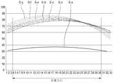
도 10은 본 발명의 실시 예에 따른 차량용 변속 장치(1)에서, 리니어 구동 모터(80)의 코일(860) 길이를 달리 함에 따른 추력 변이량을 도시한 그래프이다.10 is a graph showing the amount of thrust variation caused by varying the length of the
도 10을 참조하면, G-a는 종래의 VCM의 추력 추이를 표시한 그래프이다.Referring to FIG. 10, G-a is a graph showing a conventional thrust transition of the VCM.
그리고, G-b는 본 발명의 실시 예에 따른 차량용 변속 장치(1)에 적용되는 리니어 구동 모터(80)와 동일 또는 유사한 구성으로, 코일(860)의 단부가 제1커버부(812) 이면과 밀착되도록 설계된 상태에서, 추력 추이를 표시한 그래프이다.Gb is the same as or similar to the
그리고, G-c는 본 발명의 실시 예에 따른 차량용 변속 장치(1)에 적용되는 리니어 구동 모터(80)와 동일 또는 유사한 구성으로, 코일(860)의 길이를 1mm 짧게 형성하여, 코일(860) 단부와 제1커버부(812) 이면과의 사이에 1mm 간격이 형성되도록 설계된 상태에서, 추력 추이를 표시한 그래프이다.The
또한, G-d는 본 발명의 실시 예에 따른 차량용 변속 장치(1)에 적용되는 리니어 구동 모터와 동일 또는 유사한 구성으로, 코일(860)의 길이를 2mm 짧게 형성하여, 코일(860) 단부와 제1커버부(812) 이면과의 사이에 2mm 간격이 형성되도록 설계된 상태에서, 추력 추이를 표시한 그래프이다.Gd is the same or similar to the linear drive motor applied to the
그리고, G-e ~ G-g는 본 발명의 실시 예에 따른 차량용 변속 장치(1)에 적용되는 리니어 구동 모터와 동일 또는 유사한 구성으로, 코일(860)의 길이를 각각 3~5mm 짧게 형성하여, 코일(860) 단부와 제1커버부(812) 이면과의 사이에 각각 3~5mm 간격이 형성되도록 설계된 상태에서, 추력 추이를 표시한 그래프이다.The lengths of the
도시된 바와 같이, 본 발명의 실시 예에 따른 차량용 변속 장치(1)에 적용되는 리니어 구동 모터(80)의 경우, 종래의 VCM에 비하여 추력이 현저하게 향상됨을 알 수 있었다.As shown in the figure, in the case of the
또한, 코일(860)의 길이를 점차적으로 줄여서, 코일(860)의 단부와 제1커버부(812) 이면과의 사이에 일정 간격이 조금씩 늘어날수록 다시 말해서, 코일(860) 단부 측 일부가 마그넷(820)과의 중첩 부위를 벗어나 제2커버부(813)와 중첩 되는 부위가 줄어들수록 유효 거리의 시작 시점에서 추력이 일정 부분 향상됨을 알 수 있었다.As the length of the
다만, 코일(860)과 제1커버부(812)와의 간격이 늘어나도록 코일(860)의 전체 길이를 축소시킬수록 유효 거리의 말단 부위에서 추력이 더 감소되는 영향이 발생될 수 있으므로, 코일(860)과 제1커버부(812)와의 간격은 1~2mm정도 이격이 이루어지도록 길이가 조절되는 것이 가장 바람직함을 확인할 수 있었다.However, as the total length of the
따라서, 코일(860)과 제1커버부(812)와의 사이에 일정 간격이 형성되도록 하여, 코일(860)과 제2커버부(813)와의 중첩 부위를 줄임에 따라 유효 거리의 시작 시점부터 향상된 추력을 나타내게 됨으로, 본 발명의 실시 예에 따른 변속 장치(1)는 주행 상황에서 특정 변속단 간의 변속을 막도록 변속 레버(10)의 조작을 방해하는 반력을 제공하여 변속 블로킹을 실제적으로 구현할 수 있게 된다.Accordingly, the
본 발명이 속하는 기술분야의 통상의 지식을 가진 자는 본 발명이 그 기술적 사상이나 필수적인 특징을 변경하지 않고서 다른 구체적인 형태로 실시될 수 있다는 것을 이해할 수 있을 것이다. 그러므로 이상에서 기술한 실시예들은 모든 면에서 예시적인 것이며 한정적이 아닌 것으로 이해해야만 한다. 본 발명의 범위는 상기 상세한 설명보다는 후술하는 특허청구범위에 의하여 나타내어지며, 특허청구범위의 의미 및 범위 그리고 그 균등 개념으로부터 도출되는 모든 변경 또는 변형된 형태가 본 발명의 범위에 포함되는 것으로 해석되어야 한다.It will be understood by those skilled in the art that the present invention may be embodied in other specific forms without departing from the spirit or essential characteristics thereof. It is therefore to be understood that the above-described embodiments are illustrative in all aspects and not restrictive. The scope of the present invention is defined by the appended claims rather than the detailed description and all changes or modifications derived from the meaning and scope of the claims and their equivalents are to be construed as being included within the scope of the present invention do.
1: 차량용 변속 장치10: 변속 레버
21: 상부 하우징22: 제1측부 하우징
23: 제2 측부 하우징24: 내부 하우징
30: 샤프트 홀더40 : 변속 레버 샤프트
70 : 링크 부재71 : 플랜지
72 : 결합조80 : 리니어 구동 모터
810 : 가변 하우징811 : 외벽
812 : 제1커버부813 : 제2커버부
814 : 공간부820 : 마그넷
830 : 요크840 : 모터 샤프트
850 : 보빈851 : 베이스 플레이트
852 : 코일 실린더860 : 코일1: vehicle transmission 10: shift lever
21: upper housing 22: first side housing
23: second side housing 24: inner housing
30: Shaft holder 40: Shifting lever shaft
70: link member 71: flange
72: Coupling tank 80: Linear drive motor
810: variable housing 811: outer wall
812: first cover part 813: second cover part
814: Space section 820: Magnet
830: yoke 840: motor shaft
850: Bobbin 851: Base plate
852: coil cylinder 860: coil
Claims (7)
Translated fromKorean상기 리니어 구동 모터는,
상기 하우징에 고정 결합되는 고정 유닛;
상기 고정 유닛에 대해 이동 가능하게 설치되며, 적어도 일부가 상기 고정 유닛의 일부와 중첩되는 외벽 및 상기 외벽의 일단으로부터 교차되는 방향으로 연장 형성되는 커버를 포함하는 가변 유닛 및;
상기 고정 유닛과 상기 가변 유닛 중, 어느 하나의 유닛에 마련되는 코일을 포함하고,
상기 커버는, 제1커버부와, 상기 제1커버부 보다 두껍게 형성되는 제2커버부를 포함하며,
상기 가변 유닛이 상기 고정 유닛 쪽으로 더 이상 이동이 제한된 위치까지 이동한 상태에서, 상기 코일은 상기 제1커버부와 일정 간격 이격되는 차량용 변속 장치.And a linear drive motor that moves the shift lever or provides a reaction force to a force that the driver operates the shift lever, wherein the housing, the shift lever,
The linear drive motor includes:
A fixed unit fixedly coupled to the housing;
A variable unit movably installed with respect to the fixed unit, the variable unit including an outer wall overlapping at least a part of the fixed unit and a cover extending in a direction intersecting from one end of the outer wall;
And a coil provided in any one of the fixed unit and the variable unit,
Wherein the cover includes a first cover portion and a second cover portion formed thicker than the first cover portion,
Wherein the coil is spaced apart from the first cover part by a predetermined distance in a state in which the variable unit is moved to a position where the movement is further restricted to the fixed unit side.
상기 코일과, 상기 제1커버부 사이의 상기 이격된 간격은 1~2mm인 차량용 변속 장치.The method according to claim 1,
Wherein the spacing between the coil and the first cover portion is 1 to 2 mm.
상기 고정 유닛은 상기 코일이 감긴 보빈을 포함하고,
상기 보빈은,
상기 하우징에 결합되는 베이스 플레이트 및 상기 베이스 플레이트의 일면으로 연장 형성되어 상기 코일이 감기는 코일 실린더를 포함하며,
상기 베이스 플레이트의 이면에는 일면 방향으로 함몰 형성된 복수의 살 빼기 홈이 형성된 차량용 변속 장치.The method according to claim 1,
Wherein the fixed unit includes a bobbin around which the coil is wound,
The bobbin
A base plate coupled to the housing, and a coil cylinder extended from one surface of the base plate to wind the coil,
Wherein the base plate has a plurality of recessed grooves formed on the back surface of the base plate.
상기 제2커버부는 상기 제1커버부로부터 상기 가변 유닛의 내측을 향해 연장 형성되어 단차를 형성하며, 상기 단차만큼 상기 제1커버부보다 두꺼운 두께를 갖는 차량용 변속 장치.The method according to claim 1,
The second cover portion extends from the first cover portion toward the inside of the variable unit to form a step, and has a thickness thicker than the first cover portion by the step.
상기 제1커버부의 두께는 상기 외벽의 두께보다 두꺼운 두께로 형성되는 차량용 변속 장치.The method according to claim 1,
And the thickness of the first cover portion is thicker than the thickness of the outer wall.
상기 제1커버부의 두께와 상기 외벽의 두께는 3 : 1의 비율로 형성되는 차량용 변속 장치.6. The method of claim 5,
Wherein the thickness of the first cover portion and the thickness of the outer wall are formed in a ratio of 3: 1.
상기 가변 하우징은, S45C, 퍼멀로이(permalloy), 아몰퍼스(amorphous), 방향성 전자강판, 무방향성 전자강판 및 순철 중 적어도 하나로 형성되는 차량용 변속 장치.The method according to claim 1,
Wherein the variable housing is formed of at least one of S45C, permalloy, amorphous, directional electromagnetic steel plate, non-directional electromagnetic steel plate, and pure iron.
Priority Applications (3)
| Application Number | Priority Date | Filing Date | Title |
|---|---|---|---|
| KR1020140194460AKR102238730B1 (en) | 2014-12-30 | 2014-12-30 | Automotive transmission |
| CN201521108549.9UCN205559761U (en) | 2014-12-26 | 2015-12-28 | Automobile speed changer |
| US14/981,411US10619732B2 (en) | 2014-12-26 | 2015-12-28 | Automotive transmission |
Applications Claiming Priority (1)
| Application Number | Priority Date | Filing Date | Title |
|---|---|---|---|
| KR1020140194460AKR102238730B1 (en) | 2014-12-30 | 2014-12-30 | Automotive transmission |
Publications (2)
| Publication Number | Publication Date |
|---|---|
| KR20160082101Atrue KR20160082101A (en) | 2016-07-08 |
| KR102238730B1 KR102238730B1 (en) | 2021-04-12 |
Family
ID=56504111
Family Applications (1)
| Application Number | Title | Priority Date | Filing Date |
|---|---|---|---|
| KR1020140194460AActiveKR102238730B1 (en) | 2014-12-26 | 2014-12-30 | Automotive transmission |
Country Status (1)
| Country | Link |
|---|---|
| KR (1) | KR102238730B1 (en) |
Citations (4)
| Publication number | Priority date | Publication date | Assignee | Title |
|---|---|---|---|---|
| US5317221A (en)* | 1991-09-04 | 1994-05-31 | Canon Kabushiki Kaisha | Linear driving device |
| US20020020236A1 (en)* | 2000-08-18 | 2002-02-21 | Alps Electric Co., Ltd. | By-wire shift lever device for vehicle |
| US7675202B1 (en)* | 2007-07-18 | 2010-03-09 | Benjamin Huang | Isotropic ring magnet linear voice coil motor |
| KR20140108555A (en) | 2011-12-19 | 2014-09-11 | 알리손 트랜스미션, 인크. | Automatic transmission with improved gear arrangement |
- 2014
- 2014-12-30KRKR1020140194460Apatent/KR102238730B1/enactiveActive
Patent Citations (4)
| Publication number | Priority date | Publication date | Assignee | Title |
|---|---|---|---|---|
| US5317221A (en)* | 1991-09-04 | 1994-05-31 | Canon Kabushiki Kaisha | Linear driving device |
| US20020020236A1 (en)* | 2000-08-18 | 2002-02-21 | Alps Electric Co., Ltd. | By-wire shift lever device for vehicle |
| US7675202B1 (en)* | 2007-07-18 | 2010-03-09 | Benjamin Huang | Isotropic ring magnet linear voice coil motor |
| KR20140108555A (en) | 2011-12-19 | 2014-09-11 | 알리손 트랜스미션, 인크. | Automatic transmission with improved gear arrangement |
Also Published As
| Publication number | Publication date |
|---|---|
| KR102238730B1 (en) | 2021-04-12 |
Similar Documents
| Publication | Publication Date | Title |
|---|---|---|
| US8763764B2 (en) | Locking apparatus for parking brake | |
| CN109995217B (en) | Actuator and vehicle transmission device including the same | |
| KR101755854B1 (en) | Electronic shift system | |
| US8844703B2 (en) | Locking apparatus for parking brake | |
| US10920879B2 (en) | Vehicular transmission | |
| US10619732B2 (en) | Automotive transmission | |
| KR101730893B1 (en) | Shift lever for vehicle | |
| KR102470442B1 (en) | Transmitter for vehicle | |
| KR20160128823A (en) | Transmission for vehicle | |
| EP3324081B1 (en) | Actuator for shift by wire automatic transmission | |
| JP2000229525A (en) | Shift lever device | |
| JP2007083844A (en) | Automatic transmission parking lock mechanism | |
| JP4163293B2 (en) | Control device for automatic transmission for vehicle | |
| KR20160082101A (en) | Automotive transmission | |
| KR102697977B1 (en) | Transmission for vehicle | |
| KR101653636B1 (en) | Automotive transmission | |
| US20140144273A1 (en) | Shift device | |
| US11485220B2 (en) | Rotary-type automotive transmission | |
| KR101928755B1 (en) | Automotive transmission | |
| US9384882B2 (en) | Noise reducing solenoid apparatus for shift lever | |
| KR101846714B1 (en) | Shift lever apparatus for electronic shift system | |
| US5035156A (en) | Ignition key-brake switch interlock for a transmission gear selector | |
| JP2008232262A (en) | Shift operation device for transmission | |
| US10626981B2 (en) | Gear shift for automotive transmission | |
| JP2012131305A (en) | Shift operating device of vehicular transmission |
Legal Events
| Date | Code | Title | Description |
|---|---|---|---|
| PA0109 | Patent application | Patent event code:PA01091R01D Comment text:Patent Application Patent event date:20141230 | |
| PG1501 | Laying open of application | ||
| PA0201 | Request for examination | Patent event code:PA02012R01D Patent event date:20191125 Comment text:Request for Examination of Application Patent event code:PA02011R01I Patent event date:20141230 Comment text:Patent Application | |
| E902 | Notification of reason for refusal | ||
| PE0902 | Notice of grounds for rejection | Comment text:Notification of reason for refusal Patent event date:20201126 Patent event code:PE09021S01D | |
| E701 | Decision to grant or registration of patent right | ||
| PE0701 | Decision of registration | Patent event code:PE07011S01D Comment text:Decision to Grant Registration Patent event date:20210401 | |
| GRNT | Written decision to grant | ||
| PR0701 | Registration of establishment | Comment text:Registration of Establishment Patent event date:20210405 Patent event code:PR07011E01D | |
| PR1002 | Payment of registration fee | Payment date:20210406 End annual number:3 Start annual number:1 | |
| PG1601 | Publication of registration | ||
| PR1001 | Payment of annual fee | Payment date:20250325 Start annual number:5 End annual number:5 |