KR20160080525A - Hinge device for folding door - Google Patents
Hinge device for folding doorDownload PDFInfo
- Publication number
- KR20160080525A KR20160080525AKR1020140192471AKR20140192471AKR20160080525AKR 20160080525 AKR20160080525 AKR 20160080525AKR 1020140192471 AKR1020140192471 AKR 1020140192471AKR 20140192471 AKR20140192471 AKR 20140192471AKR 20160080525 AKR20160080525 AKR 20160080525A
- Authority
- KR
- South Korea
- Prior art keywords
- hinge
- shaft
- portions
- door
- holder
- Prior art date
- Legal status (The legal status is an assumption and is not a legal conclusion. Google has not performed a legal analysis and makes no representation as to the accuracy of the status listed.)
- Granted
Links
Images


Classifications
- E—FIXED CONSTRUCTIONS
- E05—LOCKS; KEYS; WINDOW OR DOOR FITTINGS; SAFES
- E05D—HINGES OR SUSPENSION DEVICES FOR DOORS, WINDOWS OR WINGS
- E05D15/00—Suspension arrangements for wings
- E05D15/26—Suspension arrangements for wings for folding wings
- E—FIXED CONSTRUCTIONS
- E05—LOCKS; KEYS; WINDOW OR DOOR FITTINGS; SAFES
- E05D—HINGES OR SUSPENSION DEVICES FOR DOORS, WINDOWS OR WINGS
- E05D7/00—Hinges or pivots of special construction
- E—FIXED CONSTRUCTIONS
- E06—DOORS, WINDOWS, SHUTTERS, OR ROLLER BLINDS IN GENERAL; LADDERS
- E06B—FIXED OR MOVABLE CLOSURES FOR OPENINGS IN BUILDINGS, VEHICLES, FENCES OR LIKE ENCLOSURES IN GENERAL, e.g. DOORS, WINDOWS, BLINDS, GATES
- E06B3/00—Window sashes, door leaves, or like elements for closing wall or like openings; Layout of fixed or moving closures, e.g. windows in wall or like openings; Features of rigidly-mounted outer frames relating to the mounting of wing frames
- E06B3/32—Arrangements of wings characterised by the manner of movement; Arrangements of movable wings in openings; Features of wings or frames relating solely to the manner of movement of the wing
- E06B3/48—Wings connected at their edges, e.g. foldable wings
- E06B3/485—Sectional doors
- E06B3/486—Sectional doors with hinges being at least partially integral part of the section panels
Landscapes
- Engineering & Computer Science (AREA)
- Mechanical Engineering (AREA)
- Civil Engineering (AREA)
- Structural Engineering (AREA)
- Hinges (AREA)
- Extensible Doors And Revolving Doors (AREA)
Abstract
Translated fromKoreanDescription
Translated fromKorean본 발명은 폴딩 도어용 힌지장치에 관한 것으로서, 보다 구체적으로는 상부힌지와, 하부힌지의 높이 조절이 육각렌지나 드라이브와 같은 간단한 도구에 의해 이루어질 수 있도록 함으로 해서 폴딩 도어의 설치 편리성을 제공하고, 사용과정에서도 도어를 분해하지 않고 간단하게 도어 높이를 조절하여 유지 보수할 수 있도록 하는 폴딩 도어용 힌지장치를 제공코자 하는 것이다.
BACKGROUND OF THE
폴딩 도어(Folding Door)란 건물벽체의 내외벽 대체용으로 사용할 수 있고 기계적 외력에 대응해 내구성이 보장되며 방음, 방풍의 효과가 있어 외부용으로도 적합하다. 또한 제품에 유리를 적용하여 시야를 확보할 수 있으며 디자인이 우수하여 내부용으로도 훌륭한 폴딩 도어로 사용되고 있다.Folding door can be used for replacing the inner and outer walls of building walls. It is durable in response to mechanical external force. It is also suitable for external use because it has soundproof and windproof effect. In addition, glass can be applied to the product to ensure visibility, and it is used as a folding door for interior applications because of its excellent design.
이러한 폴딩 도어는 공간을 가치 있게 활용하고자 기존문들의 50% 개폐구조를 90% 이상으로 열리게 하여 주거용으로는 넓은 생활공간을 그리고 상가용으로는 고객들의 접근성을 용이하게 하여 주로 고급 레스토랑, 아파트, 주택, 상가 등의 출입구 또는 분합문에 쓰이는 추세이다.This folding door opens up more than 90% of the 50% opening / closing structure of the existing doors in order to utilize the valuable space, so it provides a wide living space for residential use and facilitates customers' access to the shopping area, , Or the entrance to a shopping mall, or a combination door.
대표적인 예로는 대한민국 등록실용신안공보(Y1)20-0439746호(2008.04.30.)의 폴딩도어 구조, 공개특허공보(A)10-2007-0112359호(2007.11.23.)의 폴딩도어 등 다양한 기술들이 제안되고 있다.A representative example is a folding door structure of the Korean Utility Model Registration Bulletin (Y1) 20-0439746 (Apr. 30, 2008), and a folding door of the official gazette (A) 10-2007-0112359 (Nov. 23, 2007) Are proposed.
그러나 상기한 종래 기술들의 경우 천장과 바닥에 설치되어 있는 레일을 따라서 슬라이드 이동하는 베어링어셈블리에 마련되는 상부힌지 및 하부힌지에 도어를 피스로 단순 고정하는 구성으로, 설치시 도어의 위치보정이나, 사용 중 도어의 중량에 의해 처짐 현상 발생으로 도어 개폐에 문제가 있는 경우 도어의 높낮이를 조절할 수 있는 수단이 부재하여 힌지와 도어를 분리 후 재조립하는 등의 번거로움이 있었다.However, in the above-described related arts, the door is simply fixed to the upper hinge and the lower hinge provided on the bearing assembly sliding along the rail installed on the ceiling and the floor, When there is a problem in opening and closing the door due to the sagging phenomenon due to the weight of the door, there is no means for adjusting the height of the door, and the hinge and the door are separated and reassembled.
또한 종래 상하부힌지의 경우 도어와 단순 고정 상태를 유지하므로, 상하부힌지에 도어 중량을 균등하게 분할하여 제공되지 못하여 일측 힌지에 도어하중이 집중되어 힌지가 파손되는 일도 빈번하게 발생하였던 것으로, 업계에서는 도어의 설치성, 설치 상태에서 도어를 쉽게 들어 올려 유지 보수할 수 있는 편리성을 제공할 수 있고, 또 사용자의 선택으로 도어의 하중을 쉽게 분산할 수 있는 구성의 폴딩 도어용 힌지장치가 요구되고 있다.
Also, since the upper and lower hinges are kept in a fixed state with the door, the door weight can not be divided equally into the upper and lower hinges, so that the door load is concentrated on the one hinge and the hinge is broken frequently. There is a demand for a hinge device for a folding door that is capable of providing ease of lifting and maintenance of the door in the installation state and in which the door can be easily lifted and that the load of the door can be easily dispersed by the user's choice .
이에 본 발명자는 상기와 같은 종래 문제점을 일소코자 본 발명을 연구 개발한 것으로서, 본 발명에서는 바닥과 천장에 설치되어 있는 레일을 따라 이동하는 상부베어링어셈블리에 아래쪽과 하부베어링어셈블리의 위쪽으로 창문프레임과 결합되어 있는 힌지를 설치함에 있어서, 상하부힌지샤프트를 회전시키는 방법으로 힌지를 이동시킬 수 있도록 구성함으로 해서 폴딩 도어의 설치 편리성을 제공하고, 사용과정에서도 도어를 분해하지 않고 간단하게 도어 높이를 조절하여 유지 보수할 수 있도록 하는 폴딩 도어용 힌지장치를 제공함에 발명의 기술적 과제를 두고 본 발명을 완성한 것이다.
Accordingly, the present invention has been made to solve the above-mentioned problems of the related art, and the present invention has been made to solve the above-mentioned problems, and it is an object of the present invention to provide an upper bearing assembly moving along a rail installed on a floor and a ceiling, The hinge can be moved by rotating the upper and lower hinge shafts so that the folding door can be conveniently installed and the door height can be easily adjusted without disassembling the door during use The present invention has been accomplished on the basis of the technical object of the present invention by providing a hinge device for a folding door.
과제 해결수단으로 본 발명에서는 첫째 천장과 바닥에 설치되어 있는 레일을 따라 이동하는 상부힌지와 하부힌지로 구성되는 폴딩 도어용 힌지장치에서, 천장에 설치된 레일을 따라 이동하는 상부베어링어셈블의 아래쪽으로 상부힌지홀더를 설치하고, 상기 상부힌지홀더의 상하부에 샤프트지지부를 돌출되도록 형성하며, 이들 샤프트지지부 사이에 도어와 결합되는 한 쌍의 힌지편에 형성된 샤프트결합구를 서로 교대로 배치하고, 샤프트지지부와 샤프트결합구에는 힌지 샤프트를 결합하는 구성으로 상부힌지를 구성함에 있어서;According to an aspect of the present invention, there is provided a hinge device for a folding door comprising a first ceiling and a lower hinge moving along a rail installed on the floor, wherein a lower portion of the upper bearing assembly, A shaft support portion is formed on the upper and lower portions of the upper hinge holder so as to protrude from the upper hinge holder and a shaft engagement portion formed in a pair of hinge pieces engaged with the door is disposed alternately between the shaft support portions, The upper hinge is configured to have a hinge shaft coupled to the shaft coupling hole.
상하부 샤프트지지부 사이의 거리가 힌지편에 형성된 샤프트결합구를 포갠 전체를 수용한 상태에서 높이조절을 위한 여유 공간이 확보될 수 있도록 구성하고; 상기 상부힌지홀더의 아래쪽 샤프트지지부에는 나사공을 형성하여 힌지샤프트에 형성된 나사부를 체결하되; 상기 나사부에는 힌지편에 형성된 샤프트결합부가 안치되는 걸림턱이 형성되는 직경을 가지며, 중심에는 렌치홈을 형성하여 힌지 샤프트를 조작할 때 걸림턱에 안치되어 있는 힌지편에 형성된 샤프트결합구가 힌지 샤프트를 따라서 승강되도록 구성한 것이다.The space between the upper and lower shaft supporting portions can be ensured in a state in which the whole of the shaft supporting portions formed on the hinge piece is accommodated; A screw hole is formed in the lower shaft support portion of the upper hinge holder to fasten a threaded portion formed on the hinge shaft; And a shaft engaging hole formed in a hinge piece formed in the engaging protrusion when the hinge shaft is operated is formed in the center of the hinge shaft so that the engaging protrusion formed on the hinge shaft is engaged with the hinge shaft, As shown in FIG.
천장과 바닥에 설치되어 있는 레일을 따라 이동하는 상부힌지와 하부힌지로 구성되는 폴딩 도어용 힌지장치에서, 바닥에 설치된 레일을 따라 이동하는 하부베어링어셈블의 위쪽으로 하부힌지홀더를 설치하고, 상기 하부힌지홀더의 상하부에 샤프트지지부를 돌출되도록 형성하며, 이들 샤프트지지부 사이에 도어와 결합되는 한 쌍의 힌지편에 형성된 샤프트결합구를 서로 교대로 배치하고, 샤프트지지부와 샤프트결합구에는 힌지 샤프트를 결합하는 구성으로 하부힌지를 구성함에 있어서;A folding door hinge device comprising a top hinge and a bottom hinge moving along a rail provided on a ceiling and a floor, wherein a lower hinge holder is provided above a lower bearing assembly moving along a rail provided on the floor, A shaft support portion is formed so as to protrude from the upper and lower portions of the hinge holder and shaft engagement portions formed in a pair of hinge pieces that are engaged with the door are alternately arranged between the shaft support portions, and a hinge shaft is engaged with the shaft support portion and the shaft engagement portion Wherein the lower hinge comprises:
상하부 샤프트지지부 사이의 거리가 힌지편에 형성된 샤프트결합구를 포갠 전체를 수용한 상태에서 높이조절을 위한 여유 공간이 확보될 수 있도록 구성하고; 상기 하부힌지홀더의 위쪽 샤프트지지부에는 상향 개구된 카운터보어를 형성하여 힌지 샤프트의 상단에 형성되며 중심에 렌치홈이 형성된 헤드부가 안치될 수 있도록 하고; 아래쪽 샤프트지지부에는 하향 개구된 카운터보어를 형성하되, 카운터보어에는 상단이 힌지편에 형성된 샤프트결합부를 지지되며 중심으로 힌지 샤프트의 하단에 형성된 나사부가 체결되는 나사공이 형성된 승강받침구를 조립하여 힌지 샤프트를 조작할 때 승강받침구가 힌지 샤프트를 따라서 승강되도록 구성한 것이다.
The space between the upper and lower shaft supporting portions can be ensured in a state in which the whole of the shaft supporting portions formed on the hinge piece is accommodated; The upper shaft support portion of the lower hinge holder is provided with a counter bore upwardly opened to form a head portion formed at the upper end of the hinge shaft and having a wrench groove at its center, The lower shaft support portion is formed with a counter bore which is opened downward. The counter bore is assembled with a screw hole having a screw hole formed at the lower end of the hinge shaft to support a shaft engaging portion formed at the upper end of the hinge piece, The elevating / lowering support is moved up and down along the hinge shaft.
본 발명에서 제공하는 폴딩 도어용 힌지장치에 의하면 상부힌지와 하부힌지에 결합되어 있는 힌지 샤프트상의 렌치홈이 서로 마주보도록 노출되어 있는 구성이므로 도어가 설치된 상태에서 육각렌치 하나로 도어의 높낮이를 쉽게 조절할 수 있다.According to the folding door hinge apparatus of the present invention, the upper and lower hinges are exposed to face each other so that the wrench grooves on the hinge shaft are opposed to each other. Therefore, the height of the door can be easily controlled by the hexagonal wrench have.
따라서 도어 설치가 간편하게 이루어질 수 있고, 도어를 사용하는 과정에서 사후 관리에 있어서도 힌지 샤프트를 회전시키는 간편한 조작으로 도어의 틀어진 상태를 교정시켜 도어 작동성을 제공할 수 있는 것이다.
Therefore, the door can be installed easily, and in the process of using the door, the door operation can be provided by correcting the wrong state of the door by a simple operation of rotating the hinge shaft.
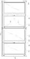
도 1은 본 발명이 적용된 폴딩 도어의 일 예를 보인 정면도
도 2는 본 발명이 적용된 폴딩 도어의 일 예를 보인 평단면도로서 도어가 닫힌 상태도
도 3은 본 발명이 적용된 폴딩 도어의 일 예를 보인 평단면도로서 도어가 열린 상태도
도 4는 본 발명에서 제공하는 폴딩 도어용 힌지장치 중 상부힌지의 일 실시례를 보인 외형 저면사시도
도 5는 도 4의 분해사시도
도 6은 도 4의 정면도 및 측단면도
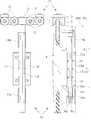
도 7은 본 발명에서 제공하는 폴딩 도어용 힌지장치 중 하부힌지의 일 실시례를 보인 외형 사시도
도 8은 도 7의 분해사시도
도 9는 도 7의 정면도 및 측단면도1 is a front view showing an example of a folding door to which the present invention is applied.
2 is a plan sectional view showing an example of a folding door to which the present invention is applied,
3 is a plan sectional view showing an example of a folding door to which the present invention is applied,
FIG. 4 is a perspective view of an outer bottom hinge of an upper hinge of a folding door according to the present invention.
Fig. 5 is an exploded perspective view of Fig.
Fig. 6 is a front view and a side sectional view of Fig. 4
FIG. 7 is a perspective view showing an example of a lower hinge of the folding door hinge apparatus provided in the present invention.
Fig. 8 is an exploded perspective view of Fig. 7
Fig. 9 is a front view and a side sectional view of Fig. 7
도 1은 본 발명이 적용된 폴딩 도어의 일 예를 보인 정면도를 도시한 것이고, 도 2는 본 발명이 적용된 폴딩 도어의 일 예를 보인 평단면도로서 도어가 닫힌 상태도, 도 3은 본 발명이 적용된 폴딩 도어의 일 예를 보인 평단면도로서 도어가 열린 상태도를 도시한 것이다.FIG. 1 is a front view showing an example of a folding door to which the present invention is applied, FIG. 2 is a plan view of a folding door to which the present invention is applied, Sectional view showing an example of a folding door, in which the door is opened.
폴딩 도어(100)는 창문, 실내의 벽체용 등 다양한 용도로 적용하여 사용할 수 있는 것으로, 도시된 바와 같이 천장과 바닥에 설치되는 레일(110)(120)을 따라서 슬라이드 이동하는 힌지장치(1)인 상부힌지(10)와 하부힌지(20)를 기준으로 양측으로 문틀프레임(130)에 고정힌지(140)로 일측이 결합된 제1도어(150)와, 고정힌지(140)도 제3도어(170)가 결합된 제2도어(160)를 결합하여 사용하는 것으로, 폴딩 도어(100)가 닫힌 상태는 도 2에 도시된 바와 같이 제1 내지 제3도어(150)(160)(170)가 일자로 배치되었다가, 폴딩 도어(100)가 열린 상태는 도 3에 도시된 바와 같이 제1내지 제3도어(150)(160)(170)가 병풍을 접어놓은 것과 같이 접어지는 상태가 되는 것이다.The folding
상기와 같은 폴딩 도어(100)는 특히 개방상태에서 폴딩 도어(100)가 가로막고 있던 넓은 공간을 제거하여 기존 창호에서는 제공할 수 없는 조망권과 통기성을 제공할 수 있으며, 실내에서 칸막이 대용으로도 사용 가능한 기능성이 있다.The folding
본 발명은 상기와 같은 폴딩 도어(100)를 구성할 때 사용되고 있는 천장과 바닥에 설치되는 레일(110)(120)을 따라서 슬라이드 이동하는 힌지장치(1)인 상부힌지(10)와 하부힌지(20)의 세부 구성을 적극적으로 개량하여 작동성을 유지하면서, 설치성 향상과 함께 유지 관리의 편리성을 제공할 수 있게 한 것으로, 이하 본 발명에서 제공하는 폴딩 도어(100)용 힌지장치(1)의 바람직한 실시례를 첨부 도면에 의거하여 설명한다.The
도 4는 본 발명에서 제공하는 폴딩 도어용 힌지장치 중 상부힌지의 일 실시례를 보인 외형 저면사시도를 도시한 것이고, 도 5는 도 4의 분해사시도, 도 6은 도 4의 정면도 및 측단면도를 도시한 것이다.4 is an exploded bottom perspective view showing an embodiment of an upper hinge of a folding door hinge apparatus provided in the present invention, FIG. 5 is an exploded perspective view of FIG. 4, FIG. 6 is a front view and a side sectional view of FIG. FIG.
본 발명에서 제공하는 폴딩 도어(100)용 힌지장치(1) 중 상부힌지(10)는 천장에 설치된 레일(110)(120)을 따라 이동하는 상부베어링어셈블리(11)의 아래쪽으로 상부힌지홀더(14)를 설치한다.The
상부베어링어셈블리(11)는 베어링 홀더(12)의 양쪽으로 베어링(13)을 결합한 구성으로 이루어지며, 베어링 홀더(12)의 중간에는 아래쪽으로 상부힌지홀더(14)를 결합한다. 바람직하기로는 상부힌지홀더(14)에 나사구멍(14a)을 형성하고, 베어링 홀더(12) 쪽에서 볼트(15)를 체결하는 방법에 의해 고정되도록 한다.The
상기 상부힌지홀더(14)에는 상하부에 샤프트지지부(14b)(14c)가 돌출 형성되며, 상하부에 형성된 샤프트지지부(14b)(14c) 사이에는 제1도어(150)와 결합되는 힌지편(16)과 제2도어(160)와 결합되는 힌지편(17)에 일체 형성되는 샤프트결합구(16a)(17a)를 서로 교대로 배치되게 한다. 이때 상하부 샤프트지지부(14b)(14c) 사이의 거리(L)가 힌지편(16)에 형성된 샤프트결합구(16a)(17a)를 포갠 전체를 수용한 상태에서 높이조절을 위한 여유공간(P)이 확보될 수 있도록 구성한다.
샤프트지지부(14b)(14c)와 샤프트결합구(16a)(17a)에는 힌지 샤프트(18)를 결합하여 제1도어(150)와 결합되는 힌지편(16)과 제2도어(160)와 결합되는 힌지편(16)이 힌지 샤프트(18)를 중심으로 해서 회동될 수 있게 한다. 샤프트지지부(14b)(14c)와 샤프트결합구(16a)(17a) 사이의 면접부에는 마찰계수를 보정할 수 있는 와셔(19)가 조립되는 것은 당연하다.The
상기와 같이 구성되는 상부힌지(10)를 구성함에 있어서, 본 발명에서는 상기 상부힌지홀더(14)의 아래쪽 샤프트지지부(14c)에 나사공(14d)을 형성한다.In the present invention, a
나사공(14d)에는 힌지 샤프트(18)에 형성된 나사부(18a)를 체결하며, 나사부(18a)에는 힌지편(16)에 형성된 샤프트결합부(16a)가 안치되는 걸림턱(18b)을 힌지 샤프트(18)보다 큰 직경으로 형성한다.The threaded
나사부(18a)에는 중심에 렌치홈(18c)을 형성하여 육각렌치가 삽입될 수 있도록 한다.A
상기와 같이 구성하는 경우 천장 쪽에 위치하는 상부힌지(10)의 힌지 샤프트(18)상에 형성된 렌치홈(18c)이 아래쪽으로 노출된 상태이므로 육각렌치의 결합 및 조작이 간편하게 이루어지게 된다.In the above configuration, the
한편 상기한 상부힌지(10)의 경우 힌지 샤프트(18)를 정회전시키면 샤프트지지부(14c)에 형성된 나사공(14d)에 나사부(18a)가 체결되며, 이때 나사부(18a) 상측의 걸림턱(18b)이 상향 이동되므로 여유공간(P) 내에서 힌지편(16)(17)에 결합되어 있는 제1,2도어(150)(160)가 들리며, 반대로 힌지 샤프트(18)를 역회전시키면 샤프트지지부(14c)에 형성된 나사공(14d)에서 나사부(18a)가 풀리면서 나사부(18a) 상측의 걸림턱(18b)이 하향 이동되므로 여유공간(P) 내에서 힌지편(16)(17)에 결합되어 있는 제1,2도어(150)(160)가 들린 상태에서 내려앉게 되는 것이다.Meanwhile, in the case of the
도 7은 본 발명에서 제공하는 폴딩 도어용 힌지장치 중 하부힌지의 일 실시례를 보인 외형 사시도를 도시한 것이고, 도 8은 도 7의 분해사시도, 도 9는 도 7의 정면도 및 측단면도를 도시한 것이다.FIG. 7 is an external perspective view showing an example of a lower hinge of a folding door hinge apparatus provided in the present invention, FIG. 8 is an exploded perspective view of FIG. 7, FIG. 9 is a front view and a side sectional view of FIG. Respectively.
본 발명에서 제공하는 폴딩 도어(100)용 힌지장치(1) 중 하부힌지(20)는 바닥에 설치된 레일(110)(120)을 따라 이동하는 하부베어링어셈블리(21)의 아래쪽으로 하부힌지홀더(24)를 설치한다.The
하부베어링어셈블리(21)는 베어링 홀더(22)의 양쪽으로 베어링(23)을 결합한 구성으로 이루어지며, 베어링 홀더(22)의 중간에는 위쪽으로 하부힌지홀더(24)를 결합한다. 바람직하기로는 하부힌지홀더(24)에 나사구멍(24a)을 형성하고, 베어링 홀더(22) 쪽에서 볼트(25)를 체결하는 방법에 의해 고정되도록 한다.The
상기 하부힌지홀더(24)에는 상하부에 샤프트지지부(24b)(24c)가 돌출 형성되며, 상하부에 형성된 샤프트지지부(24b)(24c) 사이에는 제1도어(150)와 결합되는 힌지편(26)과 제2도어(160)와 결합되는 힌지편(26)에 일체 형성되는 샤프트결합구(26a)(27a)를 서로 교대로 배치되게 한다. 이때 상하부 샤프트지지부(24b)(24c) 사이의 거리(L)가 힌지편(26)에 형성된 샤프트결합구(26a)(27a)를 포갠 전체를 수용한 상태에서 높이조절을 위한 여유공간(P)이 확보될 수 있도록 구성한다.
샤프트지지부(24b)(24c)와 샤프트결합구(26a)(27a)에는 힌지 샤프트(28)를 결합하여 제1도어(150)와 결합되는 힌지편(26)과 제2도어(160)와 결합되는 힌지편(26)이 힌지 샤프트(28)를 중심으로 해서 회동될 수 있게 한다. 샤프트지지부(24b)(24c)와 샤프트결합구(26a)(27a) 사이의 면접부에는 마찰계수를 보정할 수 있는 와셔(29)가 조립되는 것은 당연하다.The
상기와 같이 구성되는 하부힌지(20)를 구성함에 있어서, 본 발명에서는 상기 하부힌지홀더(24)의 위쪽 샤프트지지부(24b)에는 상향 개구된 카운터보어(24d)를 형성하여 힌지 샤프트(28)의 상단에 형성되며 중심에 렌치홈(28b)이 형성된 헤드부(28a)가 안치될 수 있도록 한다.In the present invention, the upper
그리고 아래쪽 샤프트지지부(24c)에는 하향 개구된 카운터보어(24e)를 형성한다. 카운터보어(24e)에는, 힌지편(26)에 형성된 샤프트결합부(26a)를 상부로 지지하며, 중심으로 힌지 샤프트(28)의 하단에 형성된 나사부(28c)가 체결되는 나사공(30a)이 형성된 승강받침구(30)를 조립하여 힌지 샤프트(28)를 조작할 때 승강받침구(30)가 힌지 샤프트(28)를 따라서 승강되도록 구성한다. 이때 카운터보어(24e)는 승강받침구(30)가 내입된 상태에서 제1,2도어(150)(160)가 들려 이동할 수 있는 여유공간(P)에 부합하는 공간이 확보됨은 당연하다.The lower
상기와 같이 구성하는 경우 천장 쪽에 위치하는 하부힌지(20)의 힌지 샤프트(28)상에 형성된 렌치홈(28b)이 위쪽으로 노출된 상태이므로 육각렌치의 결합 및 조작이 간편하게 이루어지게 된다.In the above configuration, since the
한편 상기한 하부힌지(20)의 경우 힌지 샤프트(28)를 정회전시키면 하부 샤프트지지부(24c)에 조립되어 있는 승강받침구(30)에 형성된 나사공(30a)에 나사부(28c)가 체결되면서 승강받침구(30)가 상향 이동되므로 여유공간(P) 내에서 힌지편(26)에 결합되어 있는 제1,2도어(150)(160)가 들리며, 반대로 힌지 샤프트(28)를 역회전시키면 승강받침구(30)에 형성된 나사공(30a)에서 나사부(28c)가 풀리면서 승강받침구(30)가 하향 이동되므로 여유공간(P) 내에서 힌지편(26)에 결합되어 있는 제1,2도어(150)(160)가 들린 상태에서 내려앉게 되는 것이다.On the other hand, in the case of the
이상과 같이 구성되는 본 발명의 폴딩 도어(100)용 힌지장치(1)를 사용할 경우 상부힌지(10)와 하부힌지(20)가 개별적으로 작동되는 것으로, 무게중심을 상부힌지(10) 또는 하부힌지(20)에 집중되도록 하거나 상하부힌지(20)에 동일하게 제공될 수 있도록 할 수 있다.When the
또한 상부힌지(10)와 하부힌지(20)에 조립되어 있는 힌지 샤프트(18)(28)상의 렌치홈(18c)(28b)이 서로 마주보는 노출형으로 구성되어 있어 도어 설치시 높이 조절이 간편하게 이루어지며, 사용 중에도 도어의 높이를 간편하게 제어할 수 있는 것으로 유지관리 측면에서도 매우 효율적인 발명이다.The
한편 본 발명에서 제공하는 폴딩 도어용 힌지장치(1)를 구성하는 상부힌지(10)와 하부힌지(20)의 경우 한쪽 힌지 샤프트를 작동시킬 때 상대쪽 힌지 샤프트가 연동하여 작동될 수 있도록 구성되어 있다.Meanwhile, in the case of the
일 예로 하부힌지(20)를 이용하여 제1,2도어(150)(160)를 들어 올리면 제1,2도어(150)(160)와 결합되어 있는 상부힌지(10)의 샤프트결합구(16a)(17a)가 힌지 샤프트(18)를 따라 슬라이드 되면서 상향 이동되므로, 하부힌지(20)의 교정 작업 후 상부힌지(10)의 힌지 샤프트(18)를 회전시켜 걸림턱(18b)을 샤프트결합부(16a)에 접하도록 이동시키면 되는 것이다.For example, when the first and
다른 예로 상부힌지(20)를 이용하여 제1,2도어(150)(160)를 들어 올리면 제1,2도어(150)(160)와 결합되어 있는 하부힌지(20)의 샤프트결합구(26a)(27a)가 힌지 샤프트(28)를 따라 슬라이드 되면서 상향 이동되므로, 상부힌지(10)의 교정 작업 후 하부힌지(20)의 힌지 샤프트(28)를 회전시켜 승강받침구(30)를 샤프트결합부(26a)에 접하도록 이동시키면 되는 것이다.As another example, when the first and
본 발명의 상세한 설명에서는 구체적인 실시례에 관해 설명하고 있으나, 본 발명의 범주에서 벗어나지 않는 한도 내에서 다양한 변형이 가능함은 물론이다. 그러므로 본 발명의 보호 범위는 설명된 실시례에 국한되어 정해져서는 안 되며, 후술하는 청구범위 뿐만 아니라 균등한 것들에 의해 정해져야 한다.
While the present invention has been described in connection with what is presently considered to be practical exemplary embodiments, it is to be understood that the invention is not limited to the disclosed embodiments. Therefore, the scope of protection of the present invention should not be limited to the described embodiment, but should be determined by the equivalents as well as the claims that follow.
1:(폴딩 도어용) 힌지장치
10:상부힌지
11:상부베어링어셈블리 12:베어링 홀더
13:베어링 14:상부힌지홀더
14a:나사구멍 14b,14c:샤프트지지부
14d:나사공 15:볼트
16,17:힌지편 16a,17a:샤프트결합구
18:힌지 샤프트 18a:나사부
18b:걸림턱 18c:렌치홈
19:와셔
20:하부힌지
21:하부베어링어셈블리 22:베어링 홀더
23:베어링 24:하부힌지홀더
24a:나사구멍 24b,24c:샤프트지지부
24d,24e:카운터보어 25:볼트
26,27:힌지편 26a,27a:샤프트결합구
28:힌지 샤프트 28a:헤드부
28b:렌치홈 28c:나사부
29:와셔 30:승강받침구
30a:나사공
100:폴딩 도어
110,120:레일 130:문틀프레임
140:고정힌지 150:제1도어
160:제2도어 170:제3도어1: (for folding door) Hinge device
10: upper hinge
11: upper bearing assembly 12: bearing holder
13: bearing 14: upper hinge holder
14a:
14d: screw 15: bolt
16, 17:
18:
18b: engaging
19: Washer
20: Lower hinge
21: Lower bearing assembly 22: Bearing holder
23: bearing 24: lower hinge holder
24a:
24d, 24e: Counter bore 25: Bolt
26, 27: hinge
28:
28b: a
29: washer 30:
30a: Naga
100: Folding door
110, 120: rail 130: door frame frame
140: fixed hinge 150: first door
160: second door 170: third door
Claims (2)
Translated fromKorean상하부 샤프트지지부(14b)(14c) 사이의 거리(L)가 힌지편(16)(17)에 형성된 샤프트결합구(16a)(17a)를 포갠 전체를 수용한 상태에서 높이조절을 위한 여유공간(P)이 확보될 수 있도록 구성하고;
상기 상부힌지홀더(14)의 아래쪽 샤프트지지부(14c)에는 나사공(14d)을 형성하여 힌지 샤프트(18)에 형성된 나사부(18a)를 체결하되;
상기 나사부(18a)에는 힌지편(16)에 형성된 샤프트결합부(16a)가 안치되는 걸림턱(18b)이 형성되는 직경을 가지며, 중심에는 렌치홈(18c)을 형성한 것을 특징으로 하는 폴딩 도어용 힌지장치.
In a hinge device 1 for a folding door 100 constituted by an upper hinge 10 and a lower hinge 20 which move along the rails 110 and 120 installed on the ceiling and the floor, The upper hinge holder 14 is provided below the upper bearing assembly 11 moving along the upper hinge holder 110 and the shaft supporting portions 14b and 14c are formed at the upper and lower portions of the upper hinge holder 14 Shaft coupling portions 16a and 17a formed on a pair of hinge pieces 16 and 17 to be coupled with the door between the shaft supporting portions 14b and 14c are alternately arranged and the shaft supporting portions 14b The upper hinge 10 is configured to connect the hinge shaft 18 to the shaft coupling holes 14a and 14a and the shaft coupling holes 16a and 17a.
The distance L between the upper and lower shaft supporting portions 14b and 14c is set to a clearance space for height adjustment in a state in which the entirety of the shaft coupling portions 16a and 17a formed in the hinge pieces 16 and 17 is accommodated P) can be secured;
A threaded hole 14d is formed in the lower shaft supporting portion 14c of the upper hinge holder 14 to fasten a threaded portion 18a formed on the hinge shaft 18;
The threaded portion 18a has a diameter for forming a locking protrusion 18b on which a shaft engaging portion 16a formed on the hinge piece 16 is formed and a wrench groove 18c is formed at the center thereof. Hinge device.
상하부 샤프트지지부(24b)(24c) 사이의 거리(L)가 힌지편(26)(27)에 형성된 샤프트결합구(26a)(27a)를 포갠 전체를 수용한 상태에서 높이조절을 위한 여유공간(P)이 확보될 수 있도록 구성하고;
상기 하부힌지홀더(24)의 위쪽 샤프트지지부(24b)에는 상향 개구된 카운터보어(24d)를 형성하여 힌지 샤프트(28)의 상단에 형성되며 중심에 렌치홈(28b)이 형성된 헤드부(28a)가 안치될 수 있도록 하고;
아래쪽 샤프트지지부(24c)에는 하향 개구된 카운터보어(24e)를 형성하되, 카운터보어(25e)에는 상단이 힌지편(26)에 형성된 샤프트결합부(26a)를 지지하며 중심으로 힌지 샤프트(28)의 하단에 형성된 나사부(28c)가 체결되는 나사공(30a)이 형성된 승강받침구(30)를 상기 여유공간(P)에 부합하는 공간이 형성되도록 조립한 것을 특징으로 하는 폴딩 도어용 힌지장치.In a hinge device 1 for a folding door 100 constituted by an upper hinge 10 and a lower hinge 20 which move along the rails 110 and 120 installed on the ceiling and the floor, The lower hinge holder 24 is installed above the lower bearing assembly 21 moving along the lower hinge holder 110 and the shaft supporting portions 24b and 24c are formed at the upper and lower portions of the lower hinge holder 24 And shaft engagement portions 26a and 27a formed on a pair of hinge pieces 26 and 27 engaged with the door between the shaft support portions 24b and 24c are alternately arranged and the shaft support portions 24b The lower hinge 20 is configured to connect the hinge shaft 28 to the shaft coupling holes 26a and 27a and the shaft coupling holes 26a and 27a.
The distance L between the upper and lower shaft support portions 24b and 24c is set to a clearance space for height adjustment in a state in which the whole of the shaft engagement portions 26a and 27a formed on the hinge pieces 26 and 27 is accommodated P) can be secured;
A head portion 28a formed at an upper end of the hinge shaft 28 and formed with a wrench groove 28b at the center thereof is formed in the upper shaft support portion 24b of the lower hinge holder 24 by forming an upwardly opened counter bore 24d, So that it can be stowed;
The lower shaft supporting portion 24c is formed with a counter bore 24e which is opened downward. The counter bore 25e supports the shaft engaging portion 26a formed at the upper end of the hinge piece 26, Wherein a space for accommodating the lift space (30) with the screw hole (30a) for fastening the screw portion (28c) formed at the lower end of the folding door (30) is formed.
Priority Applications (2)
| Application Number | Priority Date | Filing Date | Title |
|---|---|---|---|
| KR1020140192471AKR101665116B1 (en) | 2014-12-29 | 2014-12-29 | Hinge device for folding door |
| CN201510193714.3ACN106150247B (en) | 2014-12-29 | 2015-04-22 | Fold door hinge |
Applications Claiming Priority (1)
| Application Number | Priority Date | Filing Date | Title |
|---|---|---|---|
| KR1020140192471AKR101665116B1 (en) | 2014-12-29 | 2014-12-29 | Hinge device for folding door |
Publications (2)
| Publication Number | Publication Date |
|---|---|
| KR20160080525Atrue KR20160080525A (en) | 2016-07-08 |
| KR101665116B1 KR101665116B1 (en) | 2016-10-24 |
Family
ID=56502905
Family Applications (1)
| Application Number | Title | Priority Date | Filing Date |
|---|---|---|---|
| KR1020140192471AActiveKR101665116B1 (en) | 2014-12-29 | 2014-12-29 | Hinge device for folding door |
Country Status (2)
| Country | Link |
|---|---|
| KR (1) | KR101665116B1 (en) |
| CN (1) | CN106150247B (en) |
Cited By (3)
| Publication number | Priority date | Publication date | Assignee | Title |
|---|---|---|---|---|
| KR102081330B1 (en)* | 2019-08-23 | 2020-02-25 | 대신알루텍 주식회사 | folding door structure |
| KR102081329B1 (en)* | 2019-08-23 | 2020-02-25 | 대신알루텍 주식회사 | folding door structure used with living room window |
| CN113764304A (en)* | 2020-06-03 | 2021-12-07 | 韩国光洋热电系统有限公司 | Substrate heat treatment furnace |
Families Citing this family (2)
| Publication number | Priority date | Publication date | Assignee | Title |
|---|---|---|---|---|
| KR102176425B1 (en)* | 2019-05-23 | 2020-11-09 | (주)다우솔루션 | Folding door hinges and folding doors hinges with rail and folding doors thereof |
| KR102223397B1 (en)* | 2020-09-24 | 2021-03-05 | (주)다우솔루션 | Folding door hinges and folding doors hinges with rail and folding doors thereof |
Citations (3)
| Publication number | Priority date | Publication date | Assignee | Title |
|---|---|---|---|---|
| JPH1150724A (en)* | 1997-08-05 | 1999-02-23 | Shinkansai Bearing Co Ltd | Window hinge |
| KR20070112359A (en) | 2007-11-05 | 2007-11-23 | 김영미 | Folding door |
| KR200439746Y1 (en) | 2008-01-28 | 2008-04-30 | 홍성주 | Folding door structure |
Family Cites Families (2)
| Publication number | Priority date | Publication date | Assignee | Title |
|---|---|---|---|---|
| CN202596391U (en)* | 2012-04-20 | 2012-12-12 | 谢锦海 | Adjusting structure of fold hanging sliding door |
| CN203925164U (en)* | 2014-06-18 | 2014-11-05 | 广东坚朗五金制品股份有限公司 | Foldable push and pull window and door system |
- 2014
- 2014-12-29KRKR1020140192471Apatent/KR101665116B1/enactiveActive
- 2015
- 2015-04-22CNCN201510193714.3Apatent/CN106150247B/ennot_activeExpired - Fee Related
Patent Citations (3)
| Publication number | Priority date | Publication date | Assignee | Title |
|---|---|---|---|---|
| JPH1150724A (en)* | 1997-08-05 | 1999-02-23 | Shinkansai Bearing Co Ltd | Window hinge |
| KR20070112359A (en) | 2007-11-05 | 2007-11-23 | 김영미 | Folding door |
| KR200439746Y1 (en) | 2008-01-28 | 2008-04-30 | 홍성주 | Folding door structure |
Cited By (3)
| Publication number | Priority date | Publication date | Assignee | Title |
|---|---|---|---|---|
| KR102081330B1 (en)* | 2019-08-23 | 2020-02-25 | 대신알루텍 주식회사 | folding door structure |
| KR102081329B1 (en)* | 2019-08-23 | 2020-02-25 | 대신알루텍 주식회사 | folding door structure used with living room window |
| CN113764304A (en)* | 2020-06-03 | 2021-12-07 | 韩国光洋热电系统有限公司 | Substrate heat treatment furnace |
Also Published As
| Publication number | Publication date |
|---|---|
| KR101665116B1 (en) | 2016-10-24 |
| CN106150247B (en) | 2018-03-09 |
| CN106150247A (en) | 2016-11-23 |
Similar Documents
| Publication | Publication Date | Title |
|---|---|---|
| KR101665116B1 (en) | Hinge device for folding door | |
| US10563450B2 (en) | Sliding barn door kit | |
| US20180058122A1 (en) | Sliding panel wheel assembly | |
| US8555948B2 (en) | Multipurpose window | |
| GR20170100357A (en) | System for the construction of a multi-functional window | |
| US8534343B2 (en) | Security window | |
| WO2015107463A1 (en) | Sliding door with magnetic support | |
| AU2020403713B2 (en) | Hidden shower door with low-rail sliding assembly | |
| JP5101151B2 (en) | Shutter device and fixtures or fixtures with shutter device | |
| KR20120115879A (en) | Door assembly of a sliding window and assembling method threreof | |
| EP3564473B1 (en) | Perimeter frame for glass doors | |
| KR101133264B1 (en) | Disconnection prevention for sash door | |
| EP3039207B1 (en) | Leaf of a sliding window or sliding door and sliding window or sliding door provided with such a leaf | |
| KR102471266B1 (en) | hinge for folding door | |
| KR20090008008U (en) | Sag prevention device for window installation | |
| KR20070020546A (en) | The upper support coupling structure of the sliding door | |
| JP2019105076A (en) | sash | |
| KR101949583B1 (en) | Two-way sliding door | |
| RU60119U1 (en) | ACCESSORIES FOR LATERAL AND VERTICAL MOVEMENT OF DOORS AND WINDOWS | |
| JP4050191B2 (en) | Summing structure in sliding doors | |
| JP2000184922A (en) | Container | |
| KR100928191B1 (en) | Sliding door | |
| KR20160119954A (en) | Roller apparatus for folding door | |
| BE1024325B1 (en) | Sliding door and combination of a guide and a carriage for such a sliding door. | |
| KR20170106849A (en) | Door system having a separate and folding structure |
Legal Events
| Date | Code | Title | Description |
|---|---|---|---|
| A201 | Request for examination | ||
| PA0109 | Patent application | St.27 status event code:A-0-1-A10-A12-nap-PA0109 | |
| PA0201 | Request for examination | St.27 status event code:A-1-2-D10-D11-exm-PA0201 | |
| R18-X000 | Changes to party contact information recorded | St.27 status event code:A-3-3-R10-R18-oth-X000 | |
| D13-X000 | Search requested | St.27 status event code:A-1-2-D10-D13-srh-X000 | |
| D14-X000 | Search report completed | St.27 status event code:A-1-2-D10-D14-srh-X000 | |
| E902 | Notification of reason for refusal | ||
| PE0902 | Notice of grounds for rejection | St.27 status event code:A-1-2-D10-D21-exm-PE0902 | |
| E13-X000 | Pre-grant limitation requested | St.27 status event code:A-2-3-E10-E13-lim-X000 | |
| P11-X000 | Amendment of application requested | St.27 status event code:A-2-2-P10-P11-nap-X000 | |
| P13-X000 | Application amended | St.27 status event code:A-2-2-P10-P13-nap-X000 | |
| PG1501 | Laying open of application | St.27 status event code:A-1-1-Q10-Q12-nap-PG1501 | |
| E701 | Decision to grant or registration of patent right | ||
| PE0701 | Decision of registration | St.27 status event code:A-1-2-D10-D22-exm-PE0701 | |
| GRNT | Written decision to grant | ||
| PR0701 | Registration of establishment | St.27 status event code:A-2-4-F10-F11-exm-PR0701 | |
| PR1002 | Payment of registration fee | St.27 status event code:A-2-2-U10-U11-oth-PR1002 Fee payment year number:1 | |
| PG1601 | Publication of registration | St.27 status event code:A-4-4-Q10-Q13-nap-PG1601 | |
| FPAY | Annual fee payment | Payment date:20190902 Year of fee payment:4 | |
| PR1001 | Payment of annual fee | St.27 status event code:A-4-4-U10-U11-oth-PR1001 Fee payment year number:4 | |
| PR1001 | Payment of annual fee | St.27 status event code:A-4-4-U10-U11-oth-PR1001 Fee payment year number:5 | |
| PR1001 | Payment of annual fee | St.27 status event code:A-4-4-U10-U11-oth-PR1001 Fee payment year number:6 | |
| PR1001 | Payment of annual fee | St.27 status event code:A-4-4-U10-U11-oth-PR1001 Fee payment year number:7 | |
| PR1001 | Payment of annual fee | St.27 status event code:A-4-4-U10-U11-oth-PR1001 Fee payment year number:8 | |
| PR1001 | Payment of annual fee | St.27 status event code:A-4-4-U10-U11-oth-PR1001 Fee payment year number:9 | |
| PN2301 | Change of applicant | St.27 status event code:A-5-5-R10-R13-asn-PN2301 St.27 status event code:A-5-5-R10-R11-asn-PN2301 | |
| PR1001 | Payment of annual fee | St.27 status event code:A-4-4-U10-U11-oth-PR1001 Fee payment year number:10 |