KR20160076657A - Counterweight Structure of 3 Wheel Electric Powered Forklift - Google Patents
Counterweight Structure of 3 Wheel Electric Powered ForkliftDownload PDFInfo
- Publication number
- KR20160076657A KR20160076657AKR1020140186942AKR20140186942AKR20160076657AKR 20160076657 AKR20160076657 AKR 20160076657AKR 1020140186942 AKR1020140186942 AKR 1020140186942AKR 20140186942 AKR20140186942 AKR 20140186942AKR 20160076657 AKR20160076657 AKR 20160076657A
- Authority
- KR
- South Korea
- Prior art keywords
- counterweight
- vehicle
- body frame
- controller
- oil tank
- Prior art date
- Legal status (The legal status is an assumption and is not a legal conclusion. Google has not performed a legal analysis and makes no representation as to the accuracy of the status listed.)
- Withdrawn
Links
- 239000010720hydraulic oilSubstances0.000claimsabstractdescription13
- 239000003921oilSubstances0.000claimsdescription14
- 238000000034methodMethods0.000claimsdescription10
- 230000005484gravityEffects0.000abstractdescription10
- 239000000463materialSubstances0.000abstractdescription5
- 238000012423maintenanceMethods0.000description5
- 238000007789sealingMethods0.000description5
- 230000000694effectsEffects0.000description3
- 238000009434installationMethods0.000description3
- 238000004519manufacturing processMethods0.000description2
- 238000010276constructionMethods0.000description1
- 238000007796conventional methodMethods0.000description1
- 238000013461designMethods0.000description1
- 230000017525heat dissipationEffects0.000description1
- 238000012986modificationMethods0.000description1
- 230000004048modificationEffects0.000description1
- 230000000630rising effectEffects0.000description1
- 238000004260weight controlMethods0.000description1
Images


Classifications
- B—PERFORMING OPERATIONS; TRANSPORTING
- B66—HOISTING; LIFTING; HAULING
- B66F—HOISTING, LIFTING, HAULING OR PUSHING, NOT OTHERWISE PROVIDED FOR, e.g. DEVICES WHICH APPLY A LIFTING OR PUSHING FORCE DIRECTLY TO THE SURFACE OF A LOAD
- B66F9/00—Devices for lifting or lowering bulky or heavy goods for loading or unloading purposes
- B66F9/06—Devices for lifting or lowering bulky or heavy goods for loading or unloading purposes movable, with their loads, on wheels or the like, e.g. fork-lift trucks
- B66F9/075—Constructional features or details
- B66F9/07504—Accessories, e.g. for towing, charging, locking
- B—PERFORMING OPERATIONS; TRANSPORTING
- B66—HOISTING; LIFTING; HAULING
- B66F—HOISTING, LIFTING, HAULING OR PUSHING, NOT OTHERWISE PROVIDED FOR, e.g. DEVICES WHICH APPLY A LIFTING OR PUSHING FORCE DIRECTLY TO THE SURFACE OF A LOAD
- B66F9/00—Devices for lifting or lowering bulky or heavy goods for loading or unloading purposes
- B66F9/06—Devices for lifting or lowering bulky or heavy goods for loading or unloading purposes movable, with their loads, on wheels or the like, e.g. fork-lift trucks
- B66F9/075—Constructional features or details
- B66F9/07509—Braking
Landscapes
- Engineering & Computer Science (AREA)
- Transportation (AREA)
- Structural Engineering (AREA)
- Civil Engineering (AREA)
- Life Sciences & Earth Sciences (AREA)
- Geology (AREA)
- Mechanical Engineering (AREA)
- Forklifts And Lifting Vehicles (AREA)
Abstract
Translated fromKoreanDescription
Translated fromKorean본 발명은 전동식 3륜 지게차의 카운터웨이트 구조에 관한 것으로서, 더욱 상세하게는, 지게차의 차체 프레임에 조립되던 스티어 액슬, 작동유 탱크, 컨트롤러, 전장품 등을 카운터웨이트에 직접 장착함으로써, 차량 프레임의 구조를 최적화하고 카운터웨이트의 모듈화를 통해 조립공정을 단순화하여 생산성을 향상시키며, 각종 부품들의 무게 중심을 차량의 후방으로 배치하여 차량의 안정성을 증대시키고, 각 부품들 간의 공간 확보로 유지보수의 편의성을 향상시킨 전동식 3륜 지게차의 카운터웨이트 구조에 관한 것이다.BACKGROUND OF THE
지게차는 고중량의 하물(荷物)을 들어올리거나 운반하는데 사용되는 산업차량으로서, 실내/실외 작업장이나 건설현장 등에서 하물을 근거리로 이동시키거나, 하물을 차량에 적재하거나 하차시킬 때 널리 사용되고 있다.Forklifts are industrial vehicles used for lifting and transporting heavy cargoes and are widely used for moving cargoes to nearby places at indoor / outdoor workplaces or construction sites, loading or unloading cargoes in vehicles.
이러한 지게차는, 동력원에 따라 엔진식 지게차와 전동식 지게차로 구분할 수 있다.Such forklifts can be divided into engine-type forklifts and electric-type forklifts according to the power source.
또한 상기 전동식 지게차는, 마스트 조립체가 승/하강 작용만 하는 카운터밸런스 타입 (Counterbalance Type)의 표준형 지게차와, 마스트 조립체가 전, 후로 이동 가능하게 구성되는 리치 타입(Reach Type) 지게차 등으로 구분할 수 있다.Also, the electric forklift can be classified into a counterweight type counterweight of a mast assembly having only a rising / falling action and a reach type forklift capable of moving the mast assembly forward and backward .
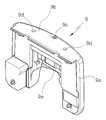
도 1은 카운터밸런스 타입의 3륜식 전동 지게차를 도시한 것이다.Fig. 1 shows a counterbalance type three-wheel electric forklift.
상기한 카운터밸런스 타입의 3륜식 전동 지게차는, 모터 등의 차량 구동원이 장착되는 차체 프레임(1)과, 상기 차체 프레임(1)의 전방에 구비되는 마스트(Mast)조립체(2)를 포함하여 이루어진다.The above-described counterbalance type three-wheel electric forklift includes a
상기 마스트 조립체(2)는, 수직방향으로 배치된 마스트 레일(Mast Rail)(3)과, 상기 마스트 레일(3)을 따라 상하로 승강 가능한 캐리지(Carriage)(4)를 구비한다.The
상기 캐리지(4)는 리프트 체인(Lift Chain)(5)에 의해 상하로 승강하며, 캐리지(4)의 전방에는 하물을 들어올리는 한 쌍의 포크(Fork)(6)가 그 폭이 조절 가능하도록 장착되어 있다.The
차체 프레임(1)의 상부에는 운전석(7)이 구비되어 있으며, 그 상부에는 운전자를 보호하기 위한 오버헤드 가드(Overhead Guard)(8)가 설치되어 있다.A driver's
또한, 지게차의 전방에는 전륜(10)이 후방에는 후륜(11)이 구비되어 있다.A
또한, 카운터밸런스 타입의 표준형 지게차는, 차량의 후방에 카운터웨이트(Counterweight)(9)를 구비하고 있다.The counterweight-type standard forklift is provided with a
상기 카운터웨이트(9)는 차체의 전방에 집중되는 하물의 무게중심을 후방으로 이동시켜 하물을 안정적으로 운송 및 승하강시키기 위한 것이다.The
도 2는 전동식 3륜 지게차에 구비되는 종래의 카운터웨이트(9)를 도시한 것이다.Fig. 2 shows a
종래의 카운터웨이트(9)는 도 2에 도시된 바와 같이, 몸체부(9a)와, 상기 몸체부(9a)의 상부에 구비되는 상부 밀폐부(9b)와, 상기 상부 밀폐부(9b)에 구비되는 견인핀(9c) 및 인양부(9d)와, 상기 몸체부(9a)의 하부 중앙에 구비되어 후륜이 장착되도록 하기 위한 개방부(9e)를 포함하여 이루어진다.2, the
한편, 카운터밸런스 타입의 표준형 지게차는 일반적으로 전륜 구동, 후륜 조향 방식을 채용하고 있다.On the other hand, the counterbalance type standard forklift generally employs front wheel drive and rear wheel steering.
즉, 차량의 전방에는 구동륜인 전륜(10)이 구비되고, 후방의 카운터웨이트(9) 하부 중앙에는 차량의 선회를 위한 조향륜인 후륜(11)이 구비된다.That is, a
상기 후륜(11)은 스티어 액슬(Steer Axle)이 조립된 차체 프레임(1)의 하부에 조립된다.The
이에 따라 구동륜인 전륜(10)이 구동되면 후륜(11)은 전륜(10)과 같이 움직이게 된다.Accordingly, when the
상기한 구조에서 운전자가 핸들을 조작하면, 유압에 의해 스티어 액슬(15)이 작동하여 후륜(11)을 선회시킴으로써 차량의 운행방향을 변경시킨다.In the above structure, when the driver operates the steering wheel, the
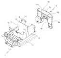
그런데 상기한 종래의 전동식 3륜 지게차는, 도 3에 도시된 바와 같이, 스티어 액슬(15)과 그 주변의 각종 부품, 예컨대, 작동유 탱크(12), 컨트롤러(13), 전장품(14) 등이 모두 차체 프레임(1)에 장착된 후, 카운터웨이트(9)와 조립되는 구조로 되어 있다.3, the conventional electric three-wheel forklift described above is constructed so that the
상기 작동유 탱크(12)는 차체 프레임(1)의 중앙 수직프레임(1c)과 후방 수직프레임(1d)의 사이에 장착된다.The working
또한 컨트롤러(13)는 차체 프레임(1)의 중앙 수직프레임(1c)의 후면에 설치되고, 전장품(14)은 후방 수직 프레임(1d)의 전면에 설치되며, 스티어 액슬(15)(도 3b 참조)은 차체 프레임(1)의 하부에 설치된다.The
즉, 스티어 액슬(15), 작동유 탱크(12), 컨트롤러(13), 전장품(14)이 모두 차체 프레임(1)에 장착된 후, 카운터웨이트(9)와 조립된다.That is, after the
이에 따라 차체 프레임(1)의 크기가 커지게 되고 그 구조가 복잡해지며, 재료비가 상승하고 제작이 용이하지 않다는 문제점이 있다.As a result, the size of the
또한, 차체 프레임(1)의 크기가 커짐에 따라 차량의 제원(차량의 전/후 길이, 선회 반경 등)을 변경하여야 하는 문제점이 있다.Further, as the size of the
또한, 차체 프레임(1) 내부에 각종 부품을 조립하기 위한 구조가 복잡해지고, 설치공간이 협소하게 되어 유지보수가 용이하지 않은 문제점이 있다.Further, the structure for assembling various components inside the
또한, 각종 부품의 모듈화 작업이 어려워 부품의 조립에 시간이 많이 소요되어 생산성이 저하되는 문제점이 있다.In addition, since modularization of various parts is difficult, it takes a lot of time to assemble the parts, resulting in a problem that productivity is lowered.
또한, 종래의 카운터웨이트 구조는 상부 밀폐부에 의해 방열이 용이하지 않은 문제점이 있다.In addition, the conventional counterweight structure has a problem that heat dissipation is not easy due to the upper sealing portion.
(특허문헌 1) : 한국 공개특허 제10-2011-0110192호(2011. 10. 06. 공개)(Patent Document 1): Korean Patent Laid-Open No. 10-2011-0110192 (published on October 10, 2011)
(특허문헌 2) : 한국 공개특허 제10-2012-0084872호(2012. 7. 31. 공개)(Patent Document 2): Published Korean Patent Application No. 10-2012-0084872 (published on July 31, 2012)
본 발명은 상기한 종래기술의 문제점을 해결하기 위한 것으로서, 차체 프레임과 카운터웨이트 사이에 구비되던 각종 부품을 차체 프레임이 아닌 카운터웨이트에 직접 장착하도록 함으로써, 차체 프레임의 구조를 단순화하고 차체 프레임 및 카운터웨이트의 구조를 최적화하는데 그 목적이 있다.SUMMARY OF THE INVENTION It is an object of the present invention to solve the problems of the prior art described above and to provide a vehicle body frame and a counterweight by directly mounting various components provided between the body frame and the counterweight, The goal is to optimize the structure of the weights.
본 발명의 다른 목적은, 각종 부품 특히 중량체인 스티어 액슬을 차량 후방의 카운터웨이트에 직접 장착하여, 차량의 무게중심을 뒤쪽으로 이동시키는 동시에 카운터웨이트의 무게중심을 아래쪽으로 이동시킴으로써, 차량의 전후 및 상하 안정성을 증대시키고, 카운터웨이트의 재료비를 절감하며 차량의 무게를 감소시켜 제조원가를 절감하는 데 있다. It is another object of the present invention to provide a steering device for a vehicle which directly attaches various parts, in particular a weighted steering axle, to a counterweight at the rear of a vehicle, moves the center of gravity of the vehicle backward and moves the center of gravity of the counterweight downward, Increase the vertical stability, reduce the material cost of the counterweight, and reduce the weight of the vehicle, thereby reducing manufacturing costs.
본 발명의 또 다른 목적은, 중량물인 카운터웨이트의 후방 형상을 차량의 선회반경을 고려하여 구성하여, 차량의 선회반경을 축소시켜 콤팩트한 제원을 확보함으로써, 선회시 주변 물체와의 충돌을 피할 수 있고 협소한 공간에서도 운행이 가능하도록 하여 작업의 효율성을 증대시키는 데 있다.It is a further object of the present invention to provide a vehicle weight control device in which a rearward shape of a heavy weight counterweight is configured in consideration of a turning radius of a vehicle to reduce a turning radius of the vehicle, And it is possible to operate in a narrow space, thereby increasing the efficiency of the work.
본 발명의 또 다른 목적은, 각종 부품들을 카운터웨이트에 모듈화 한 후 차체 프레임과 조립함으로써, 조립공수를 절감하여 생산성을 향상시키는 데 있다.Another object of the present invention is to improve the productivity by modularizing various parts in a counterweight and then assembling the parts with the body frame, thereby reducing assembly costs.
본 발명의 또 다른 목적은, 스티어 액슬을 카운터웨이트의 하부에 직접 장착함으로써 조립 및 분해가 용이하도록 하는 데 있다.It is still another object of the present invention to make it easy to assemble and disassemble by mounting the steering axle directly under the counterweight.
본 발명의 또 다른 목적은, 카운터웨이트에 장착되는 부품들 간의 설치 공간을 확대하여 유지보수의 편의성을 향상시키는 데 있다.Another object of the present invention is to increase the installation space between the parts mounted on the counterweight to improve the convenience of maintenance.
본 발명의 또 다른 목적은, 카운터웨이트의 상부 공간을 통해 차량에서 발생하는 열이 효율적으로 방출되도록 하는 데 있다.It is a further object of the present invention to provide efficient discharge of heat generated in a vehicle through an upper space of a counterweight.
본 발명의 또 다른 목적은, 차량을 용이하게 견인할 수 있고, 카운터웨이트를 용이하게 인양할 수 있도록 하는 데 있다.Yet another object of the present invention is to make it possible to easily pull the vehicle and to easily lift the counterweight.
상기한 목적을 달성하기 위하여 본 발명은, 차체 프레임과, 상기 차체 프레임의 전방에 구비되는 마스트조립체와, 수직방향으로 배치된 마스트 레일과, 상기 마스트 레일을 따라 상하로 승강 가능한 캐리지와, 상기 캐리지의 전방에 구비되어 그 폭이 조절가능하도록 구비되는 한 쌍의 포크와, 차체 프레임의 상부에 구비되는 운전석과, 상기 운전석의 상부에 구비되는 오버헤드 가드와, 차량의 후방에 구비되는 카운터웨이트를 포함하여 이루어지는 전동식 3륜 지게차에 있어서, 상기 카운터웨이트는, 몸체부의 일측에 구비되는 작동유 탱크 장착부와, 몸체부의 타측에 구비되는 컨트롤러 장착부를 포함하여 구성되어, 작동유 탱크 및 컨트롤러 등의 부품이 카운터웨이트와 일체로 모듈화되어 조립된 후, 차체 프레임과 조립되는 것을 특징으로 한다.In accordance with one aspect of the present invention, there is provided a car frame including a body frame, a mast assembly provided in front of the body frame, a mast rail arranged in a vertical direction, a carriage vertically movable along the mast rail, A pair of forks provided in front of the driver's seat and adjustable in width, a driver's seat provided on the vehicle's frame, an overhead guard provided on the driver's seat, and a counterweight provided on the rear of the vehicle Wherein the counterweight includes a working oil tank mounting portion provided on one side of the body portion and a controller mounting portion provided on the other side of the body portion so that the components such as the working oil tank and the controller are mounted on the counterweight And then assembled with the vehicle body frame.
또한, 상기 카운터웨이트의 개방부 하부 중앙에 스티어 액슬이 직접 장착되는 것을 특징으로 한다.Further, the steering axle is directly mounted on the lower center of the opening portion of the counterweight.
또한, 상기 컨트롤러 장착부는, 카운터웨이트 몸체부의 내측 수직면에 구비되는 제2 컨트롤러 장착부와, 차체 프레임의 후방 수직프레임의 후면에 구비되는 제1 컨트롤러 장착부를 포함하는 것을 특징으로 한다.The controller mounting portion includes a second controller mounting portion provided on an inner vertical surface of the counterweight body and a first controller mounting portion provided on the rear surface of the rear vertical frame of the body frame.
또한, 상기 작동유 탱크 장착부에 장착되는 작동유 탱크의 상부에 전장품이 직접 또는 모듈화되어 조립되는 것을 특징으로 한다.Also, electrical parts are directly or modularly assembled to an upper portion of a hydraulic oil tank mounted on the hydraulic oil tank mounting portion.
또한, 상기 카운터웨이트의 몸체부는 상부가 트인 구조로 형성되는 것을 특징으로 한다.Further, the body portion of the counterweight is formed in a structure in which the upper portion is curved.
또한, 상기 카운터웨이트의 몸체부의 상부 양쪽 단부에 단품 및 모듈 조립시 카운터웨이트를 인양하기 위한 인양부가 구비되는 것을 특징으로 한다.In addition, a hoisting portion for lifting the counterweight is assembled to both end portions of the upper portion of the body portion of the counterweight and when assembling the module.
또한, 상기 인양부는 카운터웨이트의 커버 결합부의 역할을 겸하도록 구성되는 것을 특징으로 한다.In addition, the lifting portion also serves as a cover engaging portion of the counterweight.
또한, 상기 카운터웨이트 몸체부 하부 양측에 하부돌기가 더 구비되는 것을 특징으로 한다.Further, a lower projection is further provided on both sides of the lower portion of the counterweight body.
본 발명에 의하면, 차체 프레임과 카운터웨이트 사이에 구비되던 각종 부품을 차체 프레임이 아닌 카운터웨이트에 직접 장착함으로써, 차체 프레임의 구조를 단순화하고 차체 프레임 및 카운터웨이트의 구조를 최적화할 수 있는 효과가 있다.According to the present invention, the structure of the vehicle body frame can be simplified and the structure of the vehicle body frame and the counterweight can be optimized by directly mounting various components provided between the vehicle body frame and the counterweight to the counterweight, not the vehicle body frame .
또한, 각종 부품 특히 중량체인 스티어 액슬을 차량 후방의 카운터웨이트에 직접 장착함으로써, 차량의 무게중심을 뒤쪽으로 이동시키는 동시에 카운터웨이트의 무게중심을 아래쪽으로 이동시켜, 차량의 전후 및 상하 안정성을 증대시킬 수 있는 효과가 있다.Further, by directly mounting various parts, particularly the weighted steering axles, to the counterweight at the rear of the vehicle, the center of gravity of the vehicle is moved backward and the center of gravity of the counterweight is moved downward to increase the stability of the front- There is an effect that can be.
또한, 카운터웨이트의 후방 형상을 차량의 선회반경을 고려하여 구성하고, 차량의 선회반경을 축소시켜 콤팩트한 제원을 확보함으로써, 선회시 주변 물체와의 충돌을 피할 수 있고 협소한 공간에서도 운행이 가능하도록 하여 작업의 효율성을 증대시킬 수 있는 효과가 있다.In addition, since the rearward shape of the counterweight is configured in consideration of the turning radius of the vehicle and the turning radius of the vehicle is reduced to secure a compact design, collision with surrounding objects can be avoided while turning, and the vehicle can be operated in a narrow space So that the efficiency of the work can be increased.
또한, 각종 부품들을 카운터웨이트에 모듈화 한 후 차체 프레임과 조립함으로써, 조립성을 개선하여 생산성을 향상시킬 수 있는 효과가 있다.Further, the various parts are modularized in the counterweight and assembled with the body frame, thereby improving the assemblability and improving the productivity.
또한, 스티어 액슬이 차체 프레임이 아닌 카운터웨이트의 하부에 직접 장착되므로, 차체 프레임 및 카운터웨이트의 구조 최적화를 통해, 프레임 및 카운터웨이트의 재료비를 절감하고 차량의 무게를 감소시켜 차량의 제조원가를 절감할 수 있는 효과가 있다.In addition, since the steering axle is directly mounted on the lower part of the counterweight, not the body frame, by optimizing the structure of the body frame and the counterweight, it is possible to reduce the material cost of the frame and the counterweight, There is an effect that can be.
또한, 카운터웨이트에 장착되는 부품들 간의 설치 공간이 확대되어 유지보수가 용이한 효과가 있다.Further, the installation space between the parts mounted on the counterweight is enlarged to facilitate maintenance.
또한, 카운터웨이트의 상부 공간을 통해 차량에서 발생하는 열이 효과적으로 방출되도록 하는 효과가 있다.Further, there is an effect that the heat generated in the vehicle is effectively released through the upper space of the counterweight.
또한, 차량을 용이하게 견인할 수 있고, 카운터웨이트를 용이하게 인양할 수 있는 효과가 있다.Further, the vehicle can be easily pulled and the counterweight can be easily lifted.
도 1은 종래의 전동식 3륜 지게차의 사시도.
도 2는 종래의 전동식 3륜 지게차의 카운터웨이트를 도시한 사시도.
도 3은 종래의 전동식 3륜 지게차에서 차체 프레임과 카운터웨이트가 조립되는 상태를 나타낸 도면으로서, 도 3a는 측면사시도이고 도 3b는 배면 사시도.
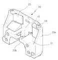
도 4는 본 발명에 따른 전동식 3륜 지게차의 카운터웨이트를 도시한 사시도.
도 5는 본 발명에 따른 전동식 3륜 지게차에서 차체 프레임과 카운터웨이트가 조립되는 상태를 나타낸 도면으로서, 도 5a는 측면사시도이고 도 5b는 배면 사시도.1 is a perspective view of a conventional electric three-wheel forklift.
2 is a perspective view showing a counterweight of a conventional electric three-wheel forklift.
Fig. 3 is a view showing a state where a body frame and a counterweight are assembled in a conventional electric three-wheel forklift, wherein Fig. 3a is a side perspective view and Fig. 3b is a rear perspective view.
4 is a perspective view showing a counterweight of an electric three-wheel forklift according to the present invention.
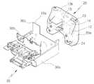
FIG. 5 is a view showing a state where a body frame and a counterweight are assembled in an electric three-wheel forklift according to the present invention. FIG. 5A is a side perspective view and FIG. 5B is a rear perspective view.
이하, 본 발명에 따른 전동식 3륜 지게차의 카운터웨이트 구조의 바람직한 실시예를 도 4 및 도 5를 참조하여 상세히 설명한다.Hereinafter, a preferred embodiment of the counterweight structure of the electric three-wheel forklift according to the present invention will be described in detail with reference to FIGS. 4 and 5. FIG.
먼저 전동식 3륜 지게차의 구조에 대하여 간략히 설명한다.First, the structure of the electric three-wheel forklift will be briefly described.
전동식 3륜 지게차는, 차체 프레임(1)과, 상기 차체 프레임(1)의 전방에 구비되는 마스트(Mast)조립체(2)와, 수직방향으로 배치된 마스트 레일(Mast Rail)(3)과, 상기 마스트 레일(3)을 따라 상하로 승강 가능한 캐리지(Carriage)(4)와, 상기 캐리지(4)의 전방에 구비되어 그 폭이 조절가능하도록 구비되는 한 쌍의 포크(Fork)(6)와, 차체 프레임(1)의 상부에 구비되는 운전석(7)과, 상기 운전석의 상부에 구비되는 오버헤드 가드(Overhead Guard)(8)와, 차량의 후방에 구비되는 카운터웨이트(Counterweight)(20)와, 전륜(10) 및 후륜(11)을 포함하여 이루어진다.The electric three-wheel forklift includes a
상기한 전동식 3륜 지게차의 구조에 대해서는 종래 기술에서 설명한 바 있으므로 중복된 설명은 생략하기로 한다.The structure of the electric three-wheel forklift described above has been described in the related art, and a duplicate description will be omitted.
본 발명에 따른 전동식 3륜 지게차의 카운터웨이트 구조는, 도 4에 도시된 바와 같이, 몸체부(20a)의 일측에 구비되는 작동유 탱크 장착부(21)와, 몸체부(20a)의 타측에 구비되는 제2 컨트롤러 장착부(22)를 포함하여 구성된다.4, the counterweight structure of the electric three-wheel forklift according to the present invention includes a working oil
상기한 구조에 의해, 작동유 탱크 및 컨트롤러 등의 부품이 카운터웨이트(20)와 일체로 모듈화되어 조립된 후, 차체 프레임(30)과 조립될 수 있다.With the above structure, the parts such as the hydraulic oil tank and the controller can be assembled with the
종래의 카운터웨이트 구조에 의하면, 도 3a 및 도 3b에 도시된 바와 같이, 작동유 탱크(12), 컨트롤러(13), 전장품(14), 스티어 액슬(15) 등의 부품이 모두 차체 프레임(1)에 장착된 후, 카운터웨이트(9)에 조립되었다.3A and 3B, all of the components such as the
즉, 종래의 컨트롤러(13)는 중앙 수직프레임(1c)의 후면에 장착되고, 전장품(14)은 후방 수직프레임(1d)의 전면에 장착되며, 작동유 탱크(12)는 중앙 수직프레임(1c)과 후방 수직프레임(1d)의 사이에 장착되었다.That is, the
이에 따라, 차체 프레임(1)의 크기가 커지게 되고 그 구조가 복잡해져, 재료비가 상승하고 프레임의 제작이 용이하지 않다는 문제가 있었다.As a result, the size of the
그러나 본 발명에 의하면, 도 5a 및 도 5b에 도시된 바와 같이, 카운터웨이트(20) 자체에 작동유 탱크(12), 전장품(14), 제1 컨트롤러(13a), 제2 컨트롤러(13b) 및 스티어 액슬(15)을 모듈화하여 직접 장착할 수 있기 때문에, 차체 프레임의 구조가 간단해지고, 차체 프레임과 카운터웨이트의 조립구조를 최적화하여 제작할 수가 있다.However, according to the present invention, as shown in Figs. 5A and 5B, the
또한, 동일한 제원에서 카운터웨이트(20)의 중량을 감소시킬 수가 있다.It is also possible to reduce the weight of the
상기 컨트롤러 장착부는, 카운터웨이트 몸체부(20a)의 내측 수직면에 구비되는 제2 컨트롤러 장착부(22)와, 차체 프레임(30)의 후방 수직프레임(30c)의 후면에 구비되는 제1 컨트롤러 장착부로 구성되는 것이 바람직하다.The controller mounting portion includes a second
그러나 이에 한정하는 것은 아니며, 상기 제1 컨트롤러 장착부와 제2 컨트롤러 장착부(22)가 모두 카운터웨이트(9)에 구비될 수도 있다.However, the present invention is not limited thereto, and both the first controller mounting portion and the second
또한 컨트롤러를 제1 컨트롤러(13a)와 제2 컨트롤러(13b)로 구분하지 않고 하나로 구성하여 카운터웨이트에 직접 장착할 수도 있다.Further, the controller may be configured as a single unit without being divided into the
또한, 상기 작동유 탱크 장착부(21)에 장착되는 작동유 탱크(12)의 상부에 전장품(14)을 직접 또는 모듈화하여 조립하는 것이 바람직하다.It is preferable that the
또한, 도 5b에 도시된 바와 같이, 상기 카운터웨이트(20)의 개방부(20d)의 하부 중앙에는 스티어 액슬(15)이 직접 장착된다.5 (b), the steering
종래에는 도 3에 도시된 바와 같이, 스티어 액슬(15)이 차체 프레임(1)의 하부에 조립되는 구조로 되어 있었다.3, the steering
그러나 본 발명에 의하면, 도 5b에 도시된 바와 같이, 스티어 액슬(15)을 카운터웨이트(20)의 중앙 하부에 직접 조립한다.However, according to the present invention, as shown in Fig. 5B, the steering
이에 따라 차체 프레임(30)과 카운터웨이트(20)의 조립 및 유지보수가 간편해지고, 스티어 액슬(15)을 카운터웨이트(20)에 직접 조립하게 되므로 차량의 강성을 증대시킬 수가 있다.Assembly and maintenance of the
또한, 상기 카운터웨이트의 몸체부(20a)는, 도 5a에 도시된 바와 같이, 상부가 트인 구조로 형성된다. 이에 따라 차량에서 발생되는 열을 효과적으로 방출시킬 수가 있다.5A, the
또한, 상기 카운터웨이트의 몸체부(20a)의 상부 양쪽 단부에는 카운터웨이트를 인양하기 위한 인양부(23)가 구비된다.Further, both ends of the upper portion of the
상기 인양부(23)의 위치는 카운터웨이트(20) 상에 장착되는 스티어 액슬(15)을 비롯한 각종 부품들의 중량에 따른 무게중심을 고려한 것이다.The position of the lifting
또한, 상기 인양부(23)는 카운터웨이트(20)의 커버(도시 생략) 결합부의 역할을 겸하도록 구성되는 것이 바람직하다.It is preferable that the lifting
즉, 카운터웨이트(20)의 상부에 별도의 커버를 구비할 경우, 상기 커버를 인양부(23)에 조립되도록 할 수 있다.That is, when a separate cover is provided on the upper portion of the
또한, 상기 카운터웨이트(20)의 몸체부(20a) 하부 양측에는 하부돌기(24)가 더 구비되는 것이 바람직하다. 이는 3륜식 지게차에 있어서 차량의 안정성을 고려한 것이다.Further, it is preferable that a
이하 본 발명에 따른 차체 프레임(30)과 카운터웨이트(20)의 조립 과정을 도 5a 및 도 5b를 참조하여 설명한다.Hereinafter, a process of assembling the
먼저 카운터웨이트(20)의 중앙에 스티어 액슬(15)을 직접 조립한다.First, the steering
이어서 작동유 탱크(12)를 카운터웨이트의 작동유 탱크 장착부(21)에 조립하고, 상기 작동유 탱크(12) 상부에 전장품(14)을 직접 또는 모듈화하여 조립한다.Subsequently, the working
그리고 제2 컨트롤러(13b)를 제2 컨트롤러 장착부(22)에 장착한다.And the
한편, 차체 프레임(30)의 후방 수직 프레임(30c)의 후면에 제1 컨트롤러(13a)를 장착한다.On the other hand, the
마지막으로 차체 프레임(30)과 카운터웨이트(20)를 조립하면, 차체 프레임(30)과 카운터웨이트(20)의 조립이 완료된다.Finally, when the
본 발명에 의하면, 스티어 액슬(15), 작동유 탱크(12), 전장품(14) 및 제2 컨트롤러(13b)를 모두 카운터웨이트(20)에 모듈화하여 장착한 후, 차체 프레임(30)과 조립할 수가 있다.According to the present invention, both the steering
이에 따라 각종 부품을 차체 프레임 상에 장착하던 종래의 방식에 비해, 차체 프레임의 구조가 간단해지고, 카운터웨이트의 모듈화 작업이 가능해지므로 조립과정을 단순화할 수 있다.As a result, the structure of the vehicle body frame is simplified and the modularization work of the counterweight can be performed as compared with the conventional method in which various parts are mounted on the vehicle body frame, so that the assembling process can be simplified.
즉, 본 발명은 단순히 균형을 맞추기 위해 장착하던 카운터웨이트에 각종 부품들을 조립하여 모듈화한 후 차체 프레임과 조립한다는데 그 특징이 있다.That is, the present invention is characterized in that various components are assembled in a counterweight, which is mounted to merely balance, to be modularized, and then assembled with a body frame.
본 발명에 의하면, 카운터웨이트에 각종 부품을 직접 장착함으로써 차량의 무게중심을 후방으로 이동시킬 수 있으므로, 동일한 제원 하에서 카운터웨이트 자체의 중량을 감소시킬 수가 있다.According to the present invention, since the center of gravity of the vehicle can be moved backward by directly attaching various components directly to the counterweight, the weight of the counterweight itself can be reduced under the same specifications.
또한, 카운터웨이트의 하부에 스티어 액슬이 직접 장착되므로, 차량의 무게중심을 하부로 이동시켜 차량의 안정성을 증대시킬 수가 있다.Further, since the steering axle is directly mounted on the lower portion of the counterweight, the center of gravity of the vehicle can be moved downward to increase the stability of the vehicle.
또한, 작동유 탱크, 전장품 및 컨트롤러를 차체 프레임이 아닌 카운터웨이트에 직접 장착함으로써 각 부품간의 공간이 확보되어 유지보수가 간편해진다.In addition, by mounting the hydraulic oil tank, electric component, and controller directly to the counterweight rather than the body frame, the space between each component is ensured and the maintenance is simplified.
이상에서는 본 발명의 바람직한 실시예를 예시적으로 설명한 것으로서 본 발명의 범위는 상기한 특정 실시예에 한정되지 아니한다. 해당 기술분야에서 통상의 지식을 가진 자라면 본 발명의 기술적 사상의 범위를 벗어남이 없이 다양한 변경 및 수정이 가능하다는 것을 이해할 수 있을 것이다.While the present invention has been described with reference to exemplary embodiments, it is to be understood that the invention is not limited to the disclosed exemplary embodiments. It will be understood by those skilled in the art that various changes and modifications may be made without departing from the scope of the present invention.
1: 차체 프레임(Frame) 1a: 측면 프레임
1b: 전방 수직프레임 1c: 중앙 수직프레임
1d: 후방 수직프레임 2: 마스트(Mast) 조립체
3: 마스트 레일(Mast Rail) 4: 캐리지(Carriage)
5: 리프트 체인(Lift Chain) 6: 포크(Fork)
7: 운전석 8: 오버헤드 가드(Overhead Guard)
9: 카운터웨이트(Counterweight) 9a: 몸체부
9b: 상부 밀폐부 9c: 견인핀
9d: 인양부 9e: 개방부
10: 전륜 11: 후륜
12: 작동유 탱크 13: 컨트롤러
13a: 제1 컨트롤러 13b: 제2 컨트롤러
14: 전장품 15: 스티어 액슬(Steer Axle)
20: 카운터웨이트 20a: 몸체부
20b: 개방부 21: 작동유 탱크 장착부
22: 제2 컨트롤러 장착부 23: 인양부
24: 하부돌기 30: 차체 프레임
30a: 측면 프레임 30b: 전방 수직프레임
30c: 후방 수직프레임1: Body frame (Frame) 1a: Side frame
1b: forward
1d: rear vertical frame 2: mast assembly
3: Mast Rail 4: Carriage
5: Lift Chain 6: Fork
7: driver's seat 8: overhead guard
9:
9b: upper sealing
9d: lifting
10: front wheel 11: rear wheel
12: Working oil tank 13: Controller
13a:
14: Electrical component 15: Steer Axle
20:
20b: opening portion 21: working oil tank mounting portion
22: second controller mounting portion 23:
24: Lower protrusion 30: Body frame
30a:
30c: rear vertical frame
Claims (8)
Translated fromKorean상기 카운터웨이트(20)는,
몸체부(20a)의 일측에 구비되는 작동유 탱크 장착부(21)와,
몸체부(20b)의 타측에 구비되는 컨트롤러 장착부를 포함하여 구성되어,
작동유 탱크(12), 전장품(14) 및 컨트롤러 등의 부품이 카운터웨이트(20)와 일체로 모듈화되어 조립된 후, 차체 프레임(30)과 조립되는 것을 특징으로 하는 전동식 3륜 지게차의 카운터웨이트 구조.A motorcycle comprising a body frame (1), a mast assembly (2) provided in front of the body frame (1), a mast rail (3) arranged in a vertical direction, A pair of forks 6 provided in front of the carriage 4 so as to be adjustable in width so as to be able to move up and down along the vehicle body frame 1, An overhead guard 8 provided at an upper portion of the driver's seat and a counterweight 20 provided at the rear of the driver's vehicle. In the wheel forklift,
The counterweight (20)
A working oil tank mounting portion 21 provided at one side of the body portion 20a,
And a controller mounting portion provided on the other side of the body portion 20b,
The counterweight structure of the electric three-wheel forklift is characterized in that the components such as the hydraulic oil tank 12, the electrical component 14, and the controller are assembled with the counterweight 20 as a unit, .
상기 카운터웨이트(20)의 개방부(20d) 하부 중앙에 스티어 액슬(15)이 직접 장착되는 것을 특징으로 하는 전동식 3륜 지게차의 카운터웨이트 구조.The method according to claim 1,
And a steering axle (15) is directly mounted on the lower center of the opening (20d) of the counterweight (20).
상기 컨트롤러 장착부는,
카운터웨이트 몸체부(20a)의 내측 수직면에 구비되는 제2 컨트롤러 장착부(22)와,
차체 프레임(30)의 후방 수직프레임(30c)의 후면에 구비되는 제1 컨트롤러 장착부를 포함하는 것을 특징으로 하는 전동식 3륜 지게차의 카운터웨이트 구조.The method according to claim 1,
The controller-
A second controller mounting portion 22 provided on an inner vertical surface of the counterweight body portion 20a,
And a first controller mounting portion provided on the rear surface of the rear vertical frame (30c) of the vehicle body frame (30).
상기 작동유 탱크 장착부(21)에 장착되는 작동유 탱크(12)의 상부에 전장품(14)이 직접 또는 모듈화되어 조립되는 것을 특징으로 하는 전동식 3륜 지게차의 카운터웨이트 구조.The method according to claim 1,
Wherein the electric component (14) is directly or modularly assembled to an upper portion of a working oil tank (12) mounted on the working oil tank mounting portion (21).
상기 카운터웨이트의 몸체부(20a)는 상부가 트인 구조로 형성되는 것을 특징으로 하는 전동식 3륜 지게차의 카운터웨이트 구조.The method according to claim 1,
The counterweight structure of an electric three-wheel forklift according to claim 1, characterized in that the body portion (20a) of the counterweight is formed as a top wall structure.
상기 카운터웨이트의 몸체부(20a)의 상부 양쪽 단부에 카운터웨이트 단품 또는 카운터웨이트 모듈을 인양하기 위한 인양부(23)가 구비되는 것을 특징으로 하는 전동식 3륜 지게차의 카운터웨이트 구조.The method according to claim 1,
And a lifting portion (23) for lifting the counterweight unit or the counterweight module is provided at both ends of the upper portion of the body portion (20a) of the counterweight.
상기 인양부(23)는 카운터웨이트(20)의 커버 결합부의 역할을 겸하도록 구성되는 것을 특징으로 하는 전동식 3륜 지게차의 카운터웨이트 구조.The method according to claim 6,
Wherein the lifting portion (23) serves also as a cover engaging portion of the counterweight (20).
상기 카운터웨이트(20) 몸체부(20a) 하부 양측에 하부돌기(24)가 더 구비되는 것을 특징으로 하는 전동식 3륜 지게차의 카운터웨이트 구조.
The method according to claim 1,
And a lower projection (24) is further provided on both sides of the lower portion of the body portion (20a) of the counterweight (20).
Priority Applications (1)
| Application Number | Priority Date | Filing Date | Title |
|---|---|---|---|
| KR1020140186942AKR20160076657A (en) | 2014-12-23 | 2014-12-23 | Counterweight Structure of 3 Wheel Electric Powered Forklift |
Applications Claiming Priority (1)
| Application Number | Priority Date | Filing Date | Title |
|---|---|---|---|
| KR1020140186942AKR20160076657A (en) | 2014-12-23 | 2014-12-23 | Counterweight Structure of 3 Wheel Electric Powered Forklift |
Publications (1)
| Publication Number | Publication Date |
|---|---|
| KR20160076657Atrue KR20160076657A (en) | 2016-07-01 |
Family
ID=56500297
Family Applications (1)
| Application Number | Title | Priority Date | Filing Date |
|---|---|---|---|
| KR1020140186942AWithdrawnKR20160076657A (en) | 2014-12-23 | 2014-12-23 | Counterweight Structure of 3 Wheel Electric Powered Forklift |
Country Status (1)
| Country | Link |
|---|---|
| KR (1) | KR20160076657A (en) |
Cited By (2)
| Publication number | Priority date | Publication date | Assignee | Title |
|---|---|---|---|---|
| KR20200076201A (en)* | 2018-12-19 | 2020-06-29 | 주식회사 두산 | Frame construction for industrial vehicle |
| KR20210014889A (en)* | 2019-07-31 | 2021-02-10 | 한국생산기술연구원 | Three-wheel electric forklift having steering type dual drive unit and, driving method thereof |
Citations (2)
| Publication number | Priority date | Publication date | Assignee | Title |
|---|---|---|---|---|
| JP2011110192A (en) | 2009-11-26 | 2011-06-09 | Kpe Inc | Game machine |
| JP2012084872A (en) | 2010-09-15 | 2012-04-26 | Tokyo Electron Ltd | Plasma etching processing apparatus, plasma etching processing method and manufacturing method of semiconductor device |
- 2014
- 2014-12-23KRKR1020140186942Apatent/KR20160076657A/ennot_activeWithdrawn
Patent Citations (2)
| Publication number | Priority date | Publication date | Assignee | Title |
|---|---|---|---|---|
| JP2011110192A (en) | 2009-11-26 | 2011-06-09 | Kpe Inc | Game machine |
| JP2012084872A (en) | 2010-09-15 | 2012-04-26 | Tokyo Electron Ltd | Plasma etching processing apparatus, plasma etching processing method and manufacturing method of semiconductor device |
Cited By (2)
| Publication number | Priority date | Publication date | Assignee | Title |
|---|---|---|---|---|
| KR20200076201A (en)* | 2018-12-19 | 2020-06-29 | 주식회사 두산 | Frame construction for industrial vehicle |
| KR20210014889A (en)* | 2019-07-31 | 2021-02-10 | 한국생산기술연구원 | Three-wheel electric forklift having steering type dual drive unit and, driving method thereof |
Similar Documents
| Publication | Publication Date | Title |
|---|---|---|
| US9475513B2 (en) | Pallet truck | |
| KR20140031578A (en) | Moving vehicle used for working | |
| US20090067969A1 (en) | Rider Lift Truck | |
| CN108640042B (en) | Jacking stand suitable for industrial vehicle | |
| KR20160076657A (en) | Counterweight Structure of 3 Wheel Electric Powered Forklift | |
| CN109319695B (en) | Jacking upright post suitable for industrial vehicle | |
| CN105819371A (en) | Walking type piling car | |
| KR101353295B1 (en) | high place working vehicles for agriculture | |
| KR20140145756A (en) | Leg Structure of Reach Type Forklift | |
| CN103288009B (en) | A kind of Small electric forklift | |
| KR102299055B1 (en) | Counterweight Structure of 4 Wheel Electric Powered Forklift | |
| CN104908843B (en) | A kind of improved assembly line dolly for automobile axle | |
| KR200473493Y1 (en) | Hand pallet truck of preventing from tumble | |
| KR102299054B1 (en) | Chassis Frame Structure of 4 Wheel Electric Powered Forklift | |
| RU2012157416A (en) | SMALL ELECTRIC LOADER | |
| KR20130132031A (en) | A mast structure in forklift for a improving rangeof view | |
| CN216580695U (en) | Drive assembly suitable for industrial vehicle | |
| KR20230120872A (en) | Counterweight structure of electric powered forklift | |
| CN210885170U (en) | Fork sidesway device | |
| CN106744505B (en) | Automatic guide transport vechicle | |
| KR20160076669A (en) | Steer Axle Structure of 4 Wheel Type Forklift | |
| KR20160076667A (en) | Chassis Frame Structure of 3 Wheel Electric Powered Forklift | |
| CN212024693U (en) | Variable-pitch electric forklift | |
| CN214828807U (en) | Stand and drive high car structure of piling up | |
| CN209815591U (en) | Arrangement mechanism of small-turning-radius industrial vehicle body |
Legal Events
| Date | Code | Title | Description |
|---|---|---|---|
| PA0109 | Patent application | Patent event code:PA01091R01D Comment text:Patent Application Patent event date:20141223 | |
| PG1501 | Laying open of application | ||
| PC1203 | Withdrawal of no request for examination | ||
| WITN | Application deemed withdrawn, e.g. because no request for examination was filed or no examination fee was paid |