KR20160073832A - Tail-sitter airplane - Google Patents
Tail-sitter airplaneDownload PDFInfo
- Publication number
- KR20160073832A KR20160073832AKR1020140182644AKR20140182644AKR20160073832AKR 20160073832 AKR20160073832 AKR 20160073832AKR 1020140182644 AKR1020140182644 AKR 1020140182644AKR 20140182644 AKR20140182644 AKR 20140182644AKR 20160073832 AKR20160073832 AKR 20160073832A
- Authority
- KR
- South Korea
- Prior art keywords
- body portion
- landing
- mode
- aircraft
- variable
- Prior art date
- Legal status (The legal status is an assumption and is not a legal conclusion. Google has not performed a legal analysis and makes no representation as to the accuracy of the status listed.)
- Granted
Links
Images


Classifications
- B—PERFORMING OPERATIONS; TRANSPORTING
- B64—AIRCRAFT; AVIATION; COSMONAUTICS
- B64C—AEROPLANES; HELICOPTERS
- B64C3/00—Wings
- B64C3/38—Adjustment of complete wings or parts thereof
- B—PERFORMING OPERATIONS; TRANSPORTING
- B64—AIRCRAFT; AVIATION; COSMONAUTICS
- B64C—AEROPLANES; HELICOPTERS
- B64C11/00—Propellers, e.g. of ducted type; Features common to propellers and rotors for rotorcraft
- B64C11/16—Blades
- B64C11/20—Constructional features
- B—PERFORMING OPERATIONS; TRANSPORTING
- B64—AIRCRAFT; AVIATION; COSMONAUTICS
- B64C—AEROPLANES; HELICOPTERS
- B64C37/00—Convertible aircraft
- Y—GENERAL TAGGING OF NEW TECHNOLOGICAL DEVELOPMENTS; GENERAL TAGGING OF CROSS-SECTIONAL TECHNOLOGIES SPANNING OVER SEVERAL SECTIONS OF THE IPC; TECHNICAL SUBJECTS COVERED BY FORMER USPC CROSS-REFERENCE ART COLLECTIONS [XRACs] AND DIGESTS
- Y02—TECHNOLOGIES OR APPLICATIONS FOR MITIGATION OR ADAPTATION AGAINST CLIMATE CHANGE
- Y02T—CLIMATE CHANGE MITIGATION TECHNOLOGIES RELATED TO TRANSPORTATION
- Y02T50/00—Aeronautics or air transport
- Y02T50/10—Drag reduction
Landscapes
- Engineering & Computer Science (AREA)
- Aviation & Aerospace Engineering (AREA)
- Mechanical Engineering (AREA)
- Toys (AREA)
Abstract
Translated fromKoreanDescription
Translated fromKorean본 발명은 고속 전진 비행을 위한 고정익(翼)비행모드와 수직이착륙을 위한 회전익비행모드로의 비행이 가능한 꼬리 이착륙형 항공기에 관한 것이다.The present invention relates to a fixed wing flight mode for fast forward flight and a tail takeoff and landing aircraft capable of flying into a flywheel flight mode for vertical takeoff and landing.
일반적으로 헬리콥터 등과 같은 수직 이착륙형 항공기는 로터의 회전력을 통해 활주로가 구비되지 않은 환경에서도 자유로운 이착륙이 가능한 장점이 있다.Vertical takeoff and landing aircraft such as a helicopter generally have an advantage of being able to take off and land freely in an environment where the runway is not provided through the rotation of the rotor.
그러나, 이러한 수직 이착륙형 항공기는 고정날개를 가지는 항공기에 비하여 고속 전진 비행 시 속도가 현저히 떨어지고, 체공성능 또한 고정날개를 가지는 항공기에 비하여 장시간 지속될 수 없는 문제점이 있었다.However, the vertical takeoff and landing aircraft has a problem in that the speed at the time of a fast forward flight is significantly lower than that of an aircraft having a fixed wing, and the airtight performance can not be maintained for a long time compared with an aircraft having a fixed wing.
따라서, 종래에는 도 5에 도시된 바와 같이, 이러한 문제점을 해결하기 위하여 항공기의 몸체가 지면에 대하여 수직 이착륙 하고, 몸체에는 고정날개 및 로터가 동시에 구비되는 꼬리 이착륙형 항공기가 개발된 바 있다.Therefore, as shown in FIG. 5, in order to solve such a problem, a tail landing type airplane has been developed in which a body of an aircraft is vertically taken off and landed on the ground, and a fixed blade and a rotor are simultaneously provided on the body.
꼬리 이착륙형 항공기는 세워진 상태로 로터의 회전 추진력을 이용하여 수직 이착륙이 가능하고, 이륙 후에는 몸체에 고정된 고정날개를 이용하여 전진 비행이 가능하다. 따라서, 기존의 단순 수직 이착륙형 항공기에 비해 체공시간이 증가하여 장시간의 비행이 가능할 수 있다.The landing and landing aircraft can be used for vertical takeoff and landing using the rotational propulsion of the rotor in a standing state, and forward flight can be made using fixed wings fixed to the body after takeoff. Therefore, compared with the conventional vertical takeoff and landing type aircraft, the flight time can be increased and the flight can be performed for a long time.
그러나, 종래의 꼬리 이착륙형 항공기는 로터가 제한된 크기로 형성되어, 이착륙 시 충분한 추력을 발생시키지 못하는 문제점이 있었다.However, the conventional tail takeoff and landing aircraft has a problem that the rotor is formed in a limited size, and sufficient thrust can not be generated during takeoff and landing.
더 자세하게는, 종래의 꼬리 이착륙형 항공기의 로터는 항공기의 고정날개 및 순항 효율을 고려하여 일정 크기로 제한된다. 즉, 로터의 크기는 항공기의 이착륙 효율에 직접적인 영향을 끼치는데, 로터가 추력기관으로 적용되는 꼬리 이착륙형 항공기의 이착륙 효율은 로터의 지름이 커질수록 증대되고, 로터의 지름이 작아질수록 저하된다. 또한, 꼬리 이착륙형 항공기의 순항 효율은 로터의 지름이 작아질수록 증대되고, 로터의 지름이 커질수록 저하된다.More specifically, the rotor of a conventional tail takeoff and landing aircraft is limited to a certain size in consideration of the fixed wing and cruising efficiency of the aircraft. That is, the size of the rotor has a direct effect on the takeoff and landing efficiency of the aircraft. The takeoff and landing efficiency of the tail takeoff and landing aircraft in which the rotor is applied as the thrust engine increases as the rotor diameter increases and decreases as the rotor diameter decreases . In addition, the cruise efficiency of the tail takeoff and landing aircraft increases as the rotor diameter decreases and decreases as the rotor diameter increases.
따라서, 종래의 꼬리 이착륙형 항공기의 로터는 순항 시 순항 효율에 영향을 최소화 할 수 있도록 제한된 크기로 형성되고, 이에 따라 종래의 꼬리 이착륙형 항공기는 이착륙 시 효율이 저하되는 문제점이 있었다.Therefore, the conventional tail take-off type rotor is formed to have a limited size so as to minimize the influence on the cruise efficiency during cruise, and thus the conventional tail take-off type aircraft has a problem in that the efficiency in takeoff and landing is lowered.
본 발명은 전술한 바와 같은 문제점들을 해결하기 위해 창출된 것으로서, 본 발명이 해결하고자 하는 과제는 몸체부에 이착륙 시에는 몸체부의 둘레를 따라 회전되어 종래의 로터 역할을 수행하고, 순항 시에는 몸체부에 고정되어 종래의 고정날개 역할을 수행하는 가변형 날개부를 형성하여 이착륙 성능 및 순항 성능을 최적화 할 수 있는 꼬리 이착륙형 항공기를 제공하는 것이다.SUMMARY OF THE INVENTION The present invention has been made in order to solve the above problems, and it is an object of the present invention to provide an air conditioner which rotates along a circumference of a body part during take-off and landing to serve as a conventional rotor, Landing airplane capable of optimizing the take-off and landing performance and the cruising performance by forming a variable wing that is fixed to the tail wing to serve as a conventional fixed wing.
상기한 과제를 달성하기 위한 본 발명의 실시예에 따른 꼬리 이착륙형 항공기는 항공기의 몸체부, 상기 몸체부에 설치되어 이착륙 시에는 상기 몸체부를 중심의로 회전하고 순항 시에는 상기 몸체부에 고정익 형태로 배치되는 가변형 날개부, 그리고 이착륙 시에는 상기 가변형 날개부의 회전에 따른 반토크를 상쇄하고, 순항 시에는 추진력을 얻기 위해 구동되는 가변형 프로펠러부를 포함한다.In order to accomplish the above object, according to an embodiment of the present invention, a tail take-off and landing type aircraft is installed in a body portion of an aircraft and a body portion thereof, and rotates about the body portion during take- And a variable propeller unit for canceling the anti-torque due to the rotation of the variable-blade unit during take-off and landing, and for driving to obtain propulsive force during cruise.
상기 가변형 날개부는 비행모드에 따라 폭의 방향이 상기 몸체부의 축 방향에 대하여 수직으로 배치되거나, 상기 몸체부의 축 방향에 대하여 평행하게 배치되는 복수 개의 날개를 포함할 수 있다.The variable wing may include a plurality of wings whose width direction is perpendicular to the axial direction of the body part or arranged parallel to the axial direction of the body part depending on a flight mode.
상기 비행 모드가 이착륙 모드로 선택될 경우, 상기 복수 개의 날개는 상기 몸체부를 중심으로 회전하고, 상기 폭의 방향은 상기 몸체부의 축 방향에 대하여 수직으로 배치될 수 있다.When the flight mode is selected as the take-off and landing mode, the plurality of blades rotate around the body, and the direction of the width may be perpendicular to the axial direction of the body.
상기 비행 모드가 순항 모드로 선택될 경우, 상기 복수 개의 날개는 고정익 형태로 상기 몸체부에 배치되고, 이때 상기 폭의 방향은 상기 몸체부의 축 방향에 대하여 평행할 수 있다.When the flight mode is selected as the cruise mode, the plurality of blades are disposed in the body portion in the form of a fixed wing, and the direction of the width may be parallel to the axial direction of the body portion.
상기 복수 개의 날개는 상기 비행 모드가 이착륙 모드로 선택될 경우, 비대칭 구조로 배치되고, 상기 비행 모드가 순항 모드로 선택될 경우, 대칭 구조로 배치될 수 있다.The plurality of blades may be arranged in an asymmetric structure when the flight mode is selected as the take-off and landing mode, and may be arranged in a symmetrical structure when the flight mode is selected as the cruise mode.
상기 복수 개의 날개에는 비행 중 양력조절을 위한 조절 날개가 더 구비될 수 있다.The plurality of blades may further include a control blade for controlling lift during flight.
상기 가변형 날개부로부터 상기 몸체부의 축 방향을 따라 전방 측으로 일정거리 이격된 상기 몸체부의 외면에는 상기 몸체부의 외측으로 연장된 복수 개의 보조 날개가 더 구비될 수 있다.And a plurality of auxiliary vanes extending outwardly from the body portion may be further provided on the outer surface of the body portion spaced a predetermined distance forward from the variable vane portion along the axial direction of the body portion.
상기 가변형 프로펠러부는 상기 복수 개의 보조 날개에 구비되며, 상기 가변형 프로펠러부는 동력 전달부, 그리고 상기 동력 전달부에 의해 회전하는 프로펠러를 포함할 수 있다.The variable propeller unit may be provided in the plurality of auxiliary vanes, and the variable propeller unit may include a power transmission unit and a propeller that is rotated by the power transmission unit.
상기 상기 가변형 프로펠러부는 상기 비행 모드가 이착륙 모드로 선택될 경우, 상기 몸체부의 축 방향에 대하여 수직된 형태로 배치되고, 상기 비행 모드가 순항 모드로 선택될 경우, 상기 몸체부의 축 방향에 대하여 평행하게 배치될 수 있다.Wherein when the flight mode is selected as the take-off and landing mode, the variable propeller unit is arranged in a shape perpendicular to the axial direction of the body part, and when the flight mode is selected as the cruise mode, .
각각의 가변형 프로펠러부에 구비되는 각각의 프로펠러는 상기 비행 모드가 이착륙 모드로 선택될 경우, 서로 반대 방향을 향하게 배치되고, 상기 비행 모드가 순항 모드로 선택될 경우, 서로 동일한 방향을 향하게 배치될 수 있다.Each of the propellers provided in each of the variable propeller units is disposed so as to face opposite directions when the flight mode is selected as the take-off and landing mode, and when the flight mode is selected as the cruise mode, have.
상기 가변형 날개부로부터 상기 몸체부의 축 방향을 따라 후방 측으로 일정 거리 이격된 상기 몸체부의 외면에는 상기 몸체부로부터 연장된 복수 개의 안정판이 더 구비될 수 있다.And a plurality of stabilizers extending from the body portion may be further provided on the outer surface of the body portion spaced a predetermined distance from the variable vane portion along the axial direction of the body portion.
본 발명에 의하면, 이착륙 시에는 항공기의 몸체부를 중심으로 회전하여 로터 역할을 수행하고, 순항 시에는 항공기의 몸체부에 고정되어 고정익 역할을 수행하는 가변형 날개부를 형성함으로써, 이착륙 성능 및 순항 성능을 최적화 할 수 있다.According to the present invention, when the take-off and landing is performed, the variable wing portion that rotates around the body portion of the aircraft to serve as a rotor and is fixed to the body portion of the aircraft during cruising to form a variable wing, can do.
또한, 가변형 날개부를 구비하여 종래의 로터 및 고정날개를 대체함으로써, 꼬리 이착륙형 항공기의 구조를 단순화 하여 제품을 경량화 함은 물론, 제조비용을 일정수준 절감할 수 있다.Further, since the variable wing portion is provided to replace the conventional rotor and fixed wing, the structure of the tail take-off and landing aircraft can be simplified to lighten the product and reduce the manufacturing cost to a certain level.
도 1은 본 발명의 실시예에 따른 꼬리 이착륙형 항공기의 이착륙 시의 모습을 나타낸 사시도이다.
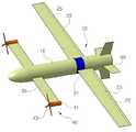
도 2는 본 발명의 실시예에 따른 꼬리 이착륙형 항공기의 순항 시의 모습을 나타낸 사시도이다.
도 3은 이착륙 및 순항 시의 본 발명의 실시예에 따른 꼬리 이착륙형 항공기를 정면에서 바라본 모습을 나타내는 도면이다.
도 4는 이착륙 및 순항 시의 본 발명의 실시예에 따른 꼬리 이착륙형 항공기를 측면에서 바라본 모습을 나타내는 도면이다.
도 5는 종래의 꼬리 이착륙형 항공기의 한 예를 나타내는 도면이다.1 is a perspective view illustrating a take-off and landing aircraft according to an embodiment of the present invention during take-off and landing.
FIG. 2 is a perspective view of a tail takeoff and landing aircraft according to an embodiment of the present invention when cruising. FIG.
3 is a front view of a tail takeoff and landing aircraft according to an embodiment of the present invention during takeoff and landing and cruise.
FIG. 4 is a side view of a tail takeoff and landing aircraft according to an embodiment of the present invention during takeoff and landing and cruise. FIG.
5 is a view showing an example of a conventional tail takeoff and landing aircraft.
이하에서 본 발명의 실시예를 첨부된 도면을 참조로 상세히 설명한다.Hereinafter, embodiments of the present invention will be described in detail with reference to the accompanying drawings.
도 1은 본 발명의 실시예에 따른 꼬리 이착륙형 항공기의 이착륙 시의 모습을 나타낸 사시도이고, 도 2는 본 발명의 실시예에 따른 꼬리 이착륙형 항공기의 순항 시의 모습을 나타낸 사시도이다. 또한, 도 3은 이착륙 및 순항 시의 본 발명의 실시예에 따른 꼬리 이착륙형 항공기를 정면에서 바라본 모습을 나타내는 도면이고, 도 4는 이착륙 및 순항 시의 본 발명의 실시예에 따른 꼬리 이착륙형 항공기를 측면에서 바라본 모습을 나타내는 도면이다.FIG. 1 is a perspective view showing a take-off and landing aircraft according to an embodiment of the present invention at the time of take-off and landing, and FIG. 2 is a perspective view illustrating a state of a take-off and landing aircraft during cruising according to an embodiment of the present invention. FIG. 3 is a front view of a tail take-off and landing type aircraft according to an embodiment of the present invention during landing and cruising; FIG. 4 is a cross- As viewed from the side.
도 1 및 도 2를 참조하면, 본 발명의 실시예에 따른 꼬리 이착륙형 항공기(이하 '꼬리 이착륙형 항공기'라 함)는 고속 전진 비행을 위한 고정익(翼) 비행모드와 수직이착륙을 위한 회전익 비행모드로의 전환이 가능한 꼬리 이착륙형 항공기로서, 원통 형상의 몸체부(10)를 포함한다.1 and 2, a tail take-off and landing type aircraft according to an embodiment of the present invention includes a wing flight mode for high-speed forward flight and a flywheel flight for vertical take- Type airplane capable of switching to a mode, and includes a
항공기의 몸체부(10)는 예컨대, 원통 형상으로 형성되어 외측에는 후술할 가변형 날개부(20)가 설치된다. 예시적으로, 몸체부(10)의 일측 단부는 공기의 저항을 최소한으로 하기 위하여 타원형의 곡면형상으로 형성되고, 몸체부(10)의 타측 단부는 평면형상으로 형성될 수 있다.The
다음으로, 본 꼬리 이착륙형 항공기는 몸체부(10)에 설치되어 이착륙 시에는 몸체부(10)를 중심으로 회전하고, 순항 시에는 고정익으로 배치되는 가변형 날개부(20)를 포함한다.Next, the tail take-off and landing type aircraft includes a
가변형 날개부(20)는 몸체부(10)에 설치되어 상기한 바와 같이 본 꼬리 이착륙형 항공기의 비행 모드(이착륙 또는 순항)에 따라 몸체부(10)를 중심으로 회전하거나, 몸체부(10)에 고정익 형태로 배치될 수 있다.The
도 3 및 도 4를 참조하면, 가변형 날개부(20)는 몸체부(10)에 설치되어 이착륙 또는 순항 중 어느 하나로 선택되는 비행모드에 따라 몸체부(10)를 중심으로 날개(23)를 선택적으로 회전시키는 구동부(주익 구동체 및 서보)(21), 그리고 구동부(21)에 의해 비행모드에 따라 폭의 방향(w)이 몸체부(10)의 축 방향(CL)에 대하여 수직으로 배치되거나, 몸체부(10)의 축 방향에 대하여 평행하게 배치되는 복수 개의 날개(예컨대 2개)(23)를 포함할 수 있다.3 and 4, the
즉, 도 1과 같이 비행 모드가 이착륙 모드로 선택될 경우, 복수 개의 날개(주익)(23)는 몸체부(10)를 중심으로 회전하고, 폭의 방향(w)은 도 3 및 도 4의 (a)와 같이 몸체부(10)의 축 방향(CL)에 대하여 수직으로 배치될 수 있다.That is, when the flight mode is selected as the take-off and landing mode as shown in FIG. 1, a plurality of
반면, 도 2와 같이 비행 모드가 순항 모드로 선택될 경우, 구동부(21)에 의해 복수 개의 날개(23)는 몸체부(10)에 고정익 형태로 배치되고, 이때 폭의 방향(w)은 도 3 및 도 4의 (b)와 같이 몸체부(10)의 축 방향(CL)에 대하여 평행하게 배치될 수 있다.2, when the flight mode is selected as the cruise mode, the plurality of
정리하면, 비행모드에 따라 구동부(21)에 의해 복수 개의 날개(23)는 로터 형태로 회전하거나, 고정익 형태로 몸체부(10)에 배치될 수 있다.In summary, the plurality of
이때, 복수 개의 날개(23)는 비행모드에 따라 대칭 또는 비대칭 구조로 배치될 수 있다.At this time, the plurality of
즉, 복수 개의 날개(23)는 비행 모드가 이착륙 모드로 선택될 경우, 도 1에 도시된 바와 같이 리딩에지(leading edge)가 서로 반대편에 위치하는 비대칭 구조로 배치되고, 비행 모드가 순항 모드로 선택될 경우, 도 2에 도시된 바와 같이 리딩에지가 서로 동일한 쪽(항공기 진행 방향)에 위치하는 대칭 구조로 배치될 수 있다. 참고로, 리딩에지는 도 2 기준으로, 날개(23)의 전방 단부를 지칭한다.That is, when the flight mode is selected as the take-off and landing mode, the plurality of
한편, 도 1 및 도 2에 도시된 바와 같이 복수 개의 날개(23)에는 비행 중 양력조절을 위한 조절 날개(aileron)(25)가 더 구비될 수 있다.1 and 2, the plurality of
또한, 복수 개의 날개(23)에는 보조 날개(canard)(30)가 더 구비될 수 있다.In addition, the plurality of
더 자세하게는, 가변형 날개부(20)로부터 몸체부(10)의 축 방향을 따라 전방 측으로 일정거리 이격된 몸체부(10)의 외면에는 몸체부(10)의 외측으로 연장된 복수 개의 보조 날개(30)가 더 구비될 수 있다.More specifically, a plurality of auxiliary blades (not shown) extending outward from the
예시적으로, 복수 개의 보조 날개(30)는 몸체부(10)의 축 방향과 수직으로 배치될 수 있으며, 가변형 날개부(20)의 날개보다 짧은 길이로 형성될 수 있다.Illustratively, the plurality of
여기서, 복수 개의 보조 날개(30)에는 추력을 발생시키는 가변형 프로펠러부(40)가 설치될 수 있다.Here, the plurality of
가변형 프로펠러부(40)는 도 3 및 도 4에 도시된 바와 같이, 예컨대 각각의 보조 날개(30)에 회전 가능하게 결합될 수 있으며, 프로펠러(43) 및 이를 구동하는 동력 전달부(41)를 포함한다. 가변형 프로펠러부(40)는 항공기 몸체부(10)의 축 방향에 대하여 수직된 형태로 배치되거나, 몸체부(10)의 축 방향에 대하여 평행하게 배치될 수 있다.3 and 4, the
또한, 가변형 프로펠러부(40)는 비행모드에 따라 반토크(anti-torque)를 상쇄하거나, 추진력을 얻을 수 있는 상태로 변경될 수 있다.In addition, the
더 자세하게는, 가변형 프로펠러부(40)는 비행 모드가 이착륙 모드로 선택될 경우, 도 4의 (a)와 같이 몸체부(10)의 축 방향에 대하여 수직된 형태로 배치되고, 비행 모드가 순항 모드로 선택될 경우, 도 4의 (b)와 같이 몸체부(10)의 축 방향에 대하여 평행하게 배치될 수 있다.More specifically, when the flight mode is selected as the take-off and landing mode, the
이때, 가변형 프로펠러부(40)에 구비되는 각 프로펠러(43)는 비행 모드가 이착륙 모드로 선택될 경우, 도 1 과 같이 서로 반대 방향을 향하여 배치되고, 비행 모드가 순항 모드로 선택될 경우, 도 2와 같이 서로 동일한 방향을 향하여 배치될 수 있다.At this time, when the flight mode is selected as the take-off and landing mode, the
따라서, 각 프로펠러(43)는 이착륙 모드로 선택될 경우, 서로 반대 방향을 향하여 배치되어 회전됨으로써, 복수 개의 날개(23)의 회전에 따른 반토크를 상쇄할 수 있고, 순항 모드로 선택될 경우, 서로 동일한 방향을 향하여 배치되어 회전됨으로써, 추진력을 얻을 수 있다.Therefore, when each of the
한편, 가변형 날개부(20)로부터 몸체부(10)의 축 방향을 따라 후방 측으로 일정 거리 이격된 몸체부(10)의 외면에는 몸체부(10)로부터 반경방향을 따라 수직으로 연장된 복수 개의 안정판(50)이 더 구비될 수 있다. 복수 개의 안정판(50)은 비행 시 조종 안정성을 유지시켜 주고, 이착륙 시에는 지면으로부터 몸체부(10)를 안정적으로 지지할 수 있는 착륙수단으로 활용 될 수 있다. 예시적으로, 복수 개의 안정판(50)은 복수 개의 보조 날개(30)의 길이보다 짧은 길이로 형성되며, 본 실시예에서는 예시적으로 4 개가 형성된 것이 도시되어 있다.On the outer surface of the
이처럼 본 발명에 의하면, 이착륙 시에는 항공기의 몸체부(10)를 중심으로 회전하여 로터 역할을 수행하고, 순항 시에는 항공기의 몸체부(10)에 고정되어 고정익 역할을 수행하는 가변형 날개부(20)를 형성함으로써, 이착륙 성능 및 순항 성능을 최적화 할 수 있다.As described above, according to the present invention, at the time of taking-off and landing, a variable wing 20 (see FIG. 1) 20, which rotates around the
또한, 가변형 날개부(20)를 구비하여 종래의 로터 및 고정날개를 대체함으로써, 꼬리 이착륙형 항공기의 구조를 단순화 하여 제품을 경량화 함은 물론, 제조비용을 일정수준 절감할 수 있다.By replacing the conventional rotor and stationary blades with the
이상에서 본 발명의 실시예를 설명하였으나, 본 발명의 권리범위는 이에 한정되지 아니하며 본 발명의 실시예로부터 본 발명이 속하는 기술분야에서 통상의 지식을 가진 자에 의해 용이하게 변경되어 균등한 것으로 인정되는 범위의 모든 변경 및 수정을 포함한다.While the present invention has been particularly shown and described with reference to exemplary embodiments, it is to be understood that the invention is not limited to the disclosed exemplary embodiments, but, on the contrary, And all changes and modifications to the scope of the invention.
10. 몸체부
20. 가변형 날개부
21. 구동부
23. 날개
25. 조절 날개
30. 보조 날개
40. 가변형 프로펠러부
41. 동력 전달부
43. 프로펠러
50. 안정판
CL. 몸체부의 축 방향
w. 날개의 폭의 방향10. Body part
20. Variable wing
21. Drive
23. Wings
25. Adjustable wing
30. Auxiliary wings
40. Variable propeller section
41. Power transmission unit
43. Propeller
50. Stability board
CL. The axial direction of the body portion
w. The direction of the width of the wing
Claims (11)
Translated fromKorean상기 몸체부에 설치되어 이착륙 시에는 상기 몸체부를 중심의로 회전하고 순항 시에는 상기 몸체부에 고정익 형태로 배치되는 가변형 날개부, 그리고
이착륙 시에는 상기 가변형 날개부의 회전에 따른 반토크를 상쇄하고, 순항 시에는 추진력을 얻기 위해 구동되는 가변형 프로펠러부
를 포함하는 꼬리 이착륙형 항공기.The body of the aircraft,
A variable wing installed on the body portion and rotatable about the body portion during take-off and landing,
When the take-off and landing is carried out, the anti-torque due to the rotation of the variable wing is canceled, and when the cruise is performed,
Aircraft on and off the tail.
상기 가변형 날개부는
비행모드에 따라 폭의 방향이 상기 몸체부의 축 방향에 대하여 수직으로 배치되거나, 상기 몸체부의 축 방향에 대하여 평행하게 배치되는 복수 개의 날개
를 포함하는 꼬리 이착륙형 항공기.The method of claim 1,
The variable wing
The direction of the width being perpendicular to the axial direction of the body part according to the flight mode, or the plurality of blades arranged in parallel with the axial direction of the body part
Aircraft on and off the tail.
상기 비행 모드가 이착륙 모드로 선택될 경우,
상기 복수 개의 날개는 상기 몸체부를 중심으로 회전하고, 상기 폭의 방향은 상기 몸체부의 축 방향에 대하여 수직으로 배치되는 꼬리 이착륙형 항공기.3. The method of claim 2,
When the flight mode is selected as the take-off and landing mode,
Wherein the plurality of blades rotate about the body portion and the direction of the width is perpendicular to the axial direction of the body portion.
상기 비행 모드가 순항 모드로 선택될 경우,
상기 복수 개의 날개는 고정익 형태로 상기 몸체부에 배치되고, 이때 상기 폭의 방향은 상기 몸체부의 축 방향에 대하여 평행한 꼬리 이착륙형 항공기.4. The method of claim 3,
When the flight mode is selected as the cruise mode,
Wherein the plurality of vanes are disposed in the body portion in the form of a fixed wing, wherein the direction of the width is parallel to the axial direction of the body portion.
상기 복수 개의 날개는
상기 비행 모드가 이착륙 모드로 선택될 경우, 비대칭 구조로 배치되고,
상기 비행 모드가 순항 모드로 선택될 경우, 대칭 구조로 배치되는
꼬리 이착륙형 항공기.5. The method of claim 4,
The plurality of blades
When the flight mode is selected as the take-off and landing mode,
When the flight mode is selected as the cruise mode,
Tertiary takeoff and landing aircraft.
상기 복수 개의 날개에는 비행 중 양력조절을 위한 조절 날개가 더 구비되는 꼬리 이착륙형 항공기.3. The method of claim 2,
Wherein the plurality of vanes further comprise control wings for controlling lifting during flight.
상기 가변형 날개부로부터 상기 몸체부의 축 방향을 따라 전방 측으로 일정거리 이격된 상기 몸체부의 외면에는
상기 몸체부의 외측으로 연장된 복수 개의 보조 날개가 더 구비되는
꼬리 이착륙형 항공기.3. The method of claim 2,
And an outer surface of the body portion spaced a predetermined distance forward from the variable vane portion along the axial direction of the body portion
And a plurality of auxiliary vanes extending outwardly from the body portion
Tertiary takeoff and landing aircraft.
상기 가변형 프로펠러부는 상기 복수 개의 보조 날개에 구비되며,
상기 가변형 프로펠러부는
동력 전달부, 그리고
상기 동력 전달부에 의해 회전하는 프로펠러
를 포함하는 꼬리 이착륙형 항공기.8. The method of claim 7,
Wherein the variable propeller unit is provided in the plurality of auxiliary vanes,
The variable propeller section
Power transmission part, and
And a propeller rotating by the power transmitting portion
Aircraft on and off the tail.
상기 상기 가변형 프로펠러부는
상기 비행 모드가 이착륙 모드로 선택될 경우, 상기 몸체부의 축 방향에 대하여 수직된 형태로 배치되고,
상기 비행 모드가 순항 모드로 선택될 경우, 상기 몸체부의 축 방향에 대하여 평행하게 배치되는 꼬리 이착륙형 항공기.9. The method of claim 8,
The variable propeller section
When the flight mode is selected as the take-off and landing mode, the airplane is arranged in a shape perpendicular to the axial direction of the body portion,
Wherein when the flight mode is selected as the cruise mode, it is disposed parallel to the axial direction of the body portion.
각각의 가변형 프로펠러부에 구비되는 각각의 프로펠러는
상기 비행 모드가 이착륙 모드로 선택될 경우, 서로 반대 방향을 향하게 배치되고,
상기 비행 모드가 순항 모드로 선택될 경우, 서로 동일한 방향을 향하게 배치되는
꼬리 이착륙형 항공기.The method of claim 9,
Each propeller provided in each variable propeller section
When the flight mode is selected as the take-off and landing mode,
When the flight mode is selected as the cruise mode,
Tertiary takeoff and landing aircraft.
상기 가변형 날개부로부터 상기 몸체부의 축 방향을 따라 후방 측으로 일정 거리 이격된 상기 몸체부의 외면에는
상기 몸체부로부터 연장된 복수 개의 안정판이 더 구비되는 꼬리 이착륙형 항공기.The method of claim 1,
And an outer surface of the body portion spaced a certain distance from the variable vane portion along the axial direction of the body portion,
And a plurality of stabilizing plates extending from the body portion.
Priority Applications (1)
| Application Number | Priority Date | Filing Date | Title |
|---|---|---|---|
| KR1020140182644AKR101663814B1 (en) | 2014-12-17 | 2014-12-17 | Tail-sitter airplane |
Applications Claiming Priority (1)
| Application Number | Priority Date | Filing Date | Title |
|---|---|---|---|
| KR1020140182644AKR101663814B1 (en) | 2014-12-17 | 2014-12-17 | Tail-sitter airplane |
Publications (2)
| Publication Number | Publication Date |
|---|---|
| KR20160073832Atrue KR20160073832A (en) | 2016-06-27 |
| KR101663814B1 KR101663814B1 (en) | 2016-10-07 |
Family
ID=56344459
Family Applications (1)
| Application Number | Title | Priority Date | Filing Date |
|---|---|---|---|
| KR1020140182644AExpired - Fee RelatedKR101663814B1 (en) | 2014-12-17 | 2014-12-17 | Tail-sitter airplane |
Country Status (1)
| Country | Link |
|---|---|
| KR (1) | KR101663814B1 (en) |
Cited By (3)
| Publication number | Priority date | Publication date | Assignee | Title |
|---|---|---|---|---|
| WO2019212744A1 (en)* | 2018-05-04 | 2019-11-07 | General Atomics Aeronautical Systems, Inc. | Aircraft |
| CN112298547A (en)* | 2020-11-27 | 2021-02-02 | 彩虹无人机科技有限公司 | A rudder-controlled vertical take-off and landing unmanned aerial vehicle and its take-off and landing control method |
| CN115783260A (en)* | 2022-12-25 | 2023-03-14 | 哈尔滨工程大学 | A new type of cross-domain aircraft |
Citations (3)
| Publication number | Priority date | Publication date | Assignee | Title |
|---|---|---|---|---|
| US20050178879A1 (en)* | 2004-01-15 | 2005-08-18 | Youbin Mao | VTOL tailsitter flying wing |
| KR101125870B1 (en) | 2011-07-29 | 2012-03-28 | 한국항공우주연구원 | The tiltrotor aircraft |
| US20130099065A1 (en)* | 2010-05-19 | 2013-04-25 | Eads Deutschland Gmbh | Tilt-wing aircraft |
- 2014
- 2014-12-17KRKR1020140182644Apatent/KR101663814B1/ennot_activeExpired - Fee Related
Patent Citations (3)
| Publication number | Priority date | Publication date | Assignee | Title |
|---|---|---|---|---|
| US20050178879A1 (en)* | 2004-01-15 | 2005-08-18 | Youbin Mao | VTOL tailsitter flying wing |
| US20130099065A1 (en)* | 2010-05-19 | 2013-04-25 | Eads Deutschland Gmbh | Tilt-wing aircraft |
| KR101125870B1 (en) | 2011-07-29 | 2012-03-28 | 한국항공우주연구원 | The tiltrotor aircraft |
Cited By (3)
| Publication number | Priority date | Publication date | Assignee | Title |
|---|---|---|---|---|
| WO2019212744A1 (en)* | 2018-05-04 | 2019-11-07 | General Atomics Aeronautical Systems, Inc. | Aircraft |
| CN112298547A (en)* | 2020-11-27 | 2021-02-02 | 彩虹无人机科技有限公司 | A rudder-controlled vertical take-off and landing unmanned aerial vehicle and its take-off and landing control method |
| CN115783260A (en)* | 2022-12-25 | 2023-03-14 | 哈尔滨工程大学 | A new type of cross-domain aircraft |
Also Published As
| Publication number | Publication date |
|---|---|
| KR101663814B1 (en) | 2016-10-07 |
Similar Documents
| Publication | Publication Date | Title |
|---|---|---|
| US11174016B2 (en) | Compound rotorcraft with propeller | |
| EP3296202B1 (en) | Wing extension winglets for tiltrotor aircraft | |
| EP3439951B1 (en) | Rotating wing assemblies for tailsitter aircraft | |
| US10106253B2 (en) | Tilting ducted fan aircraft generating a pitch control moment | |
| EP3483064B1 (en) | Tilting proprotor with segmented duct | |
| RU2631728C1 (en) | Combined aircraft equipped with moment compensation device and method for forming additional rotation moment for mentioned aircraft | |
| US9409643B2 (en) | Helicopter with cross-flow fan | |
| US10343774B2 (en) | Quad rotor aircraft with fixed wing and variable tail surfaces | |
| CN105083551B (en) | One kind can tiltrotor and its control method | |
| JP2019532871A5 (en) | ||
| KR101755278B1 (en) | Vertical takeoff and landing unmanned aerial vehicle having fixed wing, equipped with hybrid propeller system | |
| US10077108B2 (en) | Vertical take-off and landing (VTOL) aircraft with exhaust deflector | |
| CN111498109A (en) | Vertical take-off and landing aircraft | |
| KR102062726B1 (en) | An aircraft and a control system of attutude of the aircraft | |
| US10464667B2 (en) | Oblique rotor-wing aircraft | |
| CN204250356U (en) | New fan wing aircraft | |
| US11254425B2 (en) | Differential blade geometry for rotor assemblies | |
| EP3181445B1 (en) | Plate member for reducing drag on a fairing of an aircraft | |
| US10011350B2 (en) | Vertical take-off and landing drag rudder | |
| KR101663814B1 (en) | Tail-sitter airplane | |
| US10220939B2 (en) | Active airflow system and method of reducing drag for aircraft | |
| KR20160072522A (en) | Tilt-rotor aircraft wing | |
| US20170174326A1 (en) | Vortex generators and method of creating vortices on an aircraft | |
| WO2010005390A1 (en) | Rotor wing concept for vtol aircraft | |
| RU180623U1 (en) | VERTICAL TAKEOFF AND LANDING PLANE |
Legal Events
| Date | Code | Title | Description |
|---|---|---|---|
| PA0109 | Patent application | St.27 status event code:A-0-1-A10-A12-nap-PA0109 | |
| PA0201 | Request for examination | St.27 status event code:A-1-2-D10-D11-exm-PA0201 | |
| D13-X000 | Search requested | St.27 status event code:A-1-2-D10-D13-srh-X000 | |
| D14-X000 | Search report completed | St.27 status event code:A-1-2-D10-D14-srh-X000 | |
| PG1501 | Laying open of application | St.27 status event code:A-1-1-Q10-Q12-nap-PG1501 | |
| E902 | Notification of reason for refusal | ||
| PE0902 | Notice of grounds for rejection | St.27 status event code:A-1-2-D10-D21-exm-PE0902 | |
| E13-X000 | Pre-grant limitation requested | St.27 status event code:A-2-3-E10-E13-lim-X000 | |
| P11-X000 | Amendment of application requested | St.27 status event code:A-2-2-P10-P11-nap-X000 | |
| P13-X000 | Application amended | St.27 status event code:A-2-2-P10-P13-nap-X000 | |
| E701 | Decision to grant or registration of patent right | ||
| PE0701 | Decision of registration | St.27 status event code:A-1-2-D10-D22-exm-PE0701 | |
| PR0701 | Registration of establishment | St.27 status event code:A-2-4-F10-F11-exm-PR0701 | |
| PR1002 | Payment of registration fee | Fee payment year number:1 St.27 status event code:A-2-2-U10-U11-oth-PR1002 | |
| PG1601 | Publication of registration | St.27 status event code:A-4-4-Q10-Q13-nap-PG1601 | |
| P22-X000 | Classification modified | St.27 status event code:A-4-4-P10-P22-nap-X000 | |
| PC1903 | Unpaid annual fee | Not in force date:20191001 Payment event data comment text:Termination Category : DEFAULT_OF_REGISTRATION_FEE St.27 status event code:A-4-4-U10-U13-oth-PC1903 | |
| PC1903 | Unpaid annual fee | Ip right cessation event data comment text:Termination Category : DEFAULT_OF_REGISTRATION_FEE Not in force date:20191001 St.27 status event code:N-4-6-H10-H13-oth-PC1903 | |
| P22-X000 | Classification modified | St.27 status event code:A-4-4-P10-P22-nap-X000 | |
| PN2301 | Change of applicant | St.27 status event code:A-5-5-R10-R11-asn-PN2301 St.27 status event code:A-5-5-R10-R13-asn-PN2301 | |
| PN2301 | Change of applicant | St.27 status event code:A-5-5-R10-R11-asn-PN2301 St.27 status event code:A-5-5-R10-R13-asn-PN2301 |