KR20160071938A - X-ray imaging apparatus - Google Patents
X-ray imaging apparatusDownload PDFInfo
- Publication number
- KR20160071938A KR20160071938AKR1020140179762AKR20140179762AKR20160071938AKR 20160071938 AKR20160071938 AKR 20160071938AKR 1020140179762 AKR1020140179762 AKR 1020140179762AKR 20140179762 AKR20140179762 AKR 20140179762AKR 20160071938 AKR20160071938 AKR 20160071938A
- Authority
- KR
- South Korea
- Prior art keywords
- arm
- ray
- patient
- illumination
- sub
- Prior art date
- Legal status (The legal status is an assumption and is not a legal conclusion. Google has not performed a legal analysis and makes no representation as to the accuracy of the status listed.)
- Ceased
Links
Images


Classifications
- A—HUMAN NECESSITIES
- A61—MEDICAL OR VETERINARY SCIENCE; HYGIENE
- A61B—DIAGNOSIS; SURGERY; IDENTIFICATION
- A61B6/00—Apparatus or devices for radiation diagnosis; Apparatus or devices for radiation diagnosis combined with radiation therapy equipment
- A61B6/50—Apparatus or devices for radiation diagnosis; Apparatus or devices for radiation diagnosis combined with radiation therapy equipment specially adapted for specific body parts; specially adapted for specific clinical applications
- A61B6/502—Apparatus or devices for radiation diagnosis; Apparatus or devices for radiation diagnosis combined with radiation therapy equipment specially adapted for specific body parts; specially adapted for specific clinical applications for diagnosis of breast, i.e. mammography
- A—HUMAN NECESSITIES
- A61—MEDICAL OR VETERINARY SCIENCE; HYGIENE
- A61B—DIAGNOSIS; SURGERY; IDENTIFICATION
- A61B6/00—Apparatus or devices for radiation diagnosis; Apparatus or devices for radiation diagnosis combined with radiation therapy equipment
- A—HUMAN NECESSITIES
- A61—MEDICAL OR VETERINARY SCIENCE; HYGIENE
- A61B—DIAGNOSIS; SURGERY; IDENTIFICATION
- A61B6/00—Apparatus or devices for radiation diagnosis; Apparatus or devices for radiation diagnosis combined with radiation therapy equipment
- A61B6/04—Positioning of patients; Tiltable beds or the like
- A61B6/0407—Supports, e.g. tables or beds, for the body or parts of the body
- A61B6/0414—Supports, e.g. tables or beds, for the body or parts of the body with compression means
- A—HUMAN NECESSITIES
- A61—MEDICAL OR VETERINARY SCIENCE; HYGIENE
- A61B—DIAGNOSIS; SURGERY; IDENTIFICATION
- A61B6/00—Apparatus or devices for radiation diagnosis; Apparatus or devices for radiation diagnosis combined with radiation therapy equipment
- A61B6/04—Positioning of patients; Tiltable beds or the like
- A61B6/0492—Positioning of patients; Tiltable beds or the like using markers or indicia for aiding patient positioning
- A—HUMAN NECESSITIES
- A61—MEDICAL OR VETERINARY SCIENCE; HYGIENE
- A61B—DIAGNOSIS; SURGERY; IDENTIFICATION
- A61B6/00—Apparatus or devices for radiation diagnosis; Apparatus or devices for radiation diagnosis combined with radiation therapy equipment
- A61B6/40—Arrangements for generating radiation specially adapted for radiation diagnosis
- A—HUMAN NECESSITIES
- A61—MEDICAL OR VETERINARY SCIENCE; HYGIENE
- A61B—DIAGNOSIS; SURGERY; IDENTIFICATION
- A61B6/00—Apparatus or devices for radiation diagnosis; Apparatus or devices for radiation diagnosis combined with radiation therapy equipment
- A61B6/46—Arrangements for interfacing with the operator or the patient
- G—PHYSICS
- G01—MEASURING; TESTING
- G01T—MEASUREMENT OF NUCLEAR OR X-RADIATION
- G01T1/00—Measuring X-radiation, gamma radiation, corpuscular radiation, or cosmic radiation
- G01T1/16—Measuring radiation intensity
- G01T1/161—Applications in the field of nuclear medicine, e.g. in vivo counting
- A—HUMAN NECESSITIES
- A61—MEDICAL OR VETERINARY SCIENCE; HYGIENE
- A61B—DIAGNOSIS; SURGERY; IDENTIFICATION
- A61B6/00—Apparatus or devices for radiation diagnosis; Apparatus or devices for radiation diagnosis combined with radiation therapy equipment
- A61B6/02—Arrangements for diagnosis sequentially in different planes; Stereoscopic radiation diagnosis
- A61B6/025—Tomosynthesis
- A—HUMAN NECESSITIES
- A61—MEDICAL OR VETERINARY SCIENCE; HYGIENE
- A61B—DIAGNOSIS; SURGERY; IDENTIFICATION
- A61B6/00—Apparatus or devices for radiation diagnosis; Apparatus or devices for radiation diagnosis combined with radiation therapy equipment
- A61B6/08—Auxiliary means for directing the radiation beam to a particular spot, e.g. using light beams
- A—HUMAN NECESSITIES
- A61—MEDICAL OR VETERINARY SCIENCE; HYGIENE
- A61B—DIAGNOSIS; SURGERY; IDENTIFICATION
- A61B6/00—Apparatus or devices for radiation diagnosis; Apparatus or devices for radiation diagnosis combined with radiation therapy equipment
- A61B6/42—Arrangements for detecting radiation specially adapted for radiation diagnosis
- A61B6/4208—Arrangements for detecting radiation specially adapted for radiation diagnosis characterised by using a particular type of detector
- A61B6/4233—Arrangements for detecting radiation specially adapted for radiation diagnosis characterised by using a particular type of detector using matrix detectors
- A—HUMAN NECESSITIES
- A61—MEDICAL OR VETERINARY SCIENCE; HYGIENE
- A61B—DIAGNOSIS; SURGERY; IDENTIFICATION
- A61B6/00—Apparatus or devices for radiation diagnosis; Apparatus or devices for radiation diagnosis combined with radiation therapy equipment
- A61B6/46—Arrangements for interfacing with the operator or the patient
- A61B6/461—Displaying means of special interest
- A61B6/463—Displaying means of special interest characterised by displaying multiple images or images and diagnostic data on one display
- A—HUMAN NECESSITIES
- A61—MEDICAL OR VETERINARY SCIENCE; HYGIENE
- A61B—DIAGNOSIS; SURGERY; IDENTIFICATION
- A61B6/00—Apparatus or devices for radiation diagnosis; Apparatus or devices for radiation diagnosis combined with radiation therapy equipment
- A61B6/54—Control of apparatus or devices for radiation diagnosis
Landscapes
- Health & Medical Sciences (AREA)
- Life Sciences & Earth Sciences (AREA)
- Engineering & Computer Science (AREA)
- Medical Informatics (AREA)
- Physics & Mathematics (AREA)
- Biomedical Technology (AREA)
- General Health & Medical Sciences (AREA)
- Molecular Biology (AREA)
- High Energy & Nuclear Physics (AREA)
- Nuclear Medicine, Radiotherapy & Molecular Imaging (AREA)
- Optics & Photonics (AREA)
- Biophysics (AREA)
- Veterinary Medicine (AREA)
- Pathology (AREA)
- Heart & Thoracic Surgery (AREA)
- Radiology & Medical Imaging (AREA)
- Surgery (AREA)
- Animal Behavior & Ethology (AREA)
- Public Health (AREA)
- Human Computer Interaction (AREA)
- Oral & Maxillofacial Surgery (AREA)
- Dentistry (AREA)
- Apparatus For Radiation Diagnosis (AREA)
- General Physics & Mathematics (AREA)
- Spectroscopy & Molecular Physics (AREA)
Abstract
Translated fromKoreanDescription
Translated fromKorean유방에 엑스선을 투과시켜 엑스선 영상을 생성하는 엑스선 영상 장치에 관한 것이다.To an x-ray imaging apparatus for generating an x-ray image by transmitting an x-ray to a breast.
엑스선 영상 장치는 대상체에 엑스선을 조사하고 대상체를 투과한 엑스선을 이용하여 대상체의 내부 영상을 획득할 수 있는 장치이다. 대상체를 구성하는 물질의 특성에 따라 엑스선의 투과성이 다르므로, 대상체를 투과한 엑스선의 강도를 검출하여 대상체의 내부구조를 영상화할 수 있다.An X-ray imaging apparatus is an apparatus that can acquire an internal image of an object by irradiating the object with the X-rays and using the X-rays transmitted through the object. Since the transmittance of the x-ray differs depending on the characteristics of the substance constituting the object, the intensity of the x-ray transmitted through the object can be detected and the internal structure of the object can be imaged.
대상체를 유방으로 하여 엑스선 영상을 촬영하는 기술을 맘모그래피(mammography)라 한다. 유방은 인체의 다른 부위와 달리 유선 조직과 지방 조직이 발달한 부위이기 때문에, 엑스선 튜브와 엑스선 검출기 사이에 위치한 유방을 압착 패들로 압착한 상태에서 엑스선 촬영을 수행한다.The technique of taking an x-ray image with the subject as a breast is called mammography. Unlike other parts of the human body, the breast is a region where the mammary glands and adipose tissue are developed. Therefore, x-rays are taken while the breast located between the x-ray tube and the x-ray detector is squeezed with a compression paddle.
맘모그래피를 수행하기 위해서는 유방이 압착된 상태에서 환자의 자세 유지가 중요한 바, 이로 인해 환자의 고통이 수반되고 환자의 자세를 가이드하는 방사선사의 작업 로드가 증가될 수 있다.In order to perform mammography, it is important to maintain the patient's posture while the breast is squeezed, which may lead to patient pain and increase the workload of the radiologist who guides the patient's posture.
맘모그래피 실행 시에 시각 또는 청각적인 인터랙션(interaction) 장치를 통해 환자의 자세를 가이드하고 환자에게 워크 플로우에 대한 정보를 제공함으로써, 환자가 안정감을 느낄 수 있게 하는 동시에 방사선사의 작업 로드를 줄여 주고 촬영의 정확도를 향상시킬 수 있는 엑스선 영상 장치를 제공한다.By guiding the patient's posture through the visual or auditory interaction device at the time of mammography operation and providing information about the workflow to the patient, the patient can feel the sense of security while reducing the work load of radiologist. Ray imaging apparatus capable of improving the accuracy of the X-ray imaging apparatus.
일 실시예에 따른 엑스선 영상 장치는, 엑스선 튜브가 장착된 튜브 헤드; 엑스선 검출기가 장착되는 검출기 장착부; 상단에 상기 튜브 헤드가 마련되고, 하단에 상기 검출기 장착부가 마련되는 암(arm); 사용자로부터 상기 암의 이동 방향이 입력되면, 상기 입력된 암의 이동 방향을 나타내는 조명부; 및 상기 조명부를 제어하는 제어부;를 포함한다.An X-ray imaging apparatus according to an embodiment includes: a tube head having an X-ray tube; A detector mount on which the x-ray detector is mounted; An arm having the tube head at the upper end and the detector mounting part at the lower end; An illumination unit for indicating a direction of movement of the arm when the movement direction of the arm is input from a user; And a control unit for controlling the illumination unit.
상기 조명부는, 상기 입력된 암의 이동 방행 에 따라 점등 또는 점멸 위치가 달라질 수 있다.The lighting unit may be turned on or off depending on the movement of the arm.
상기 조명부는, 상기 튜브 헤드에 형성되는 헤드 조명을 포함할 수 있다.The illumination unit may include a headlight formed on the tube head.
상기 헤드 조명은, 상기 튜브 헤드의 전면에 형성되는 전면 헤드 조명; 상기 튜브 헤드의 좌측면에 형성되는 좌측 헤드 조명; 및 상기 튜브 헤드의 우측면에 형성되는 우측 헤드 조명;을 포함할 수 있다.The headlight includes: front head illumination formed on a front surface of the tube head; A left headlight formed on a left side surface of the tube head; And a right headlight formed on a right side surface of the tube head.
상기 제어부는, 상기 입력된 이동 방향이 상측 방향이면 상기 전면 헤드 조명을 점등 또는 점멸시킬 수 있다.The control unit may turn on or blink the front headlight when the input direction is the upward direction.
상기 제어부는, 상기 입력된 이동 방향이 좌측 방향이면 상기 좌측 헤드 조명을 점등 또는 점멸시킬 수 있다.The control unit may turn on or blink the left headlight when the input moving direction is the left direction.
상기 제어부는, 상기 입력된 이동 방향이 우측 방향이면 상기 우측 헤드 조명을 점등 또는 점멸시킬 수 있다.The control unit may turn on or blink the right headlight when the input movement direction is the right direction.
상기 제어부는, 상기 입력된 암의 이동 방향이 확정되면, 상기 입력된 방향에 따라 상기 암을 이동시킬 수 있다.The control unit may move the arm according to the input direction when the input direction of the arm is determined.
상기 제어부는, 상기 암의 이동 방향이 입력된 이후에 상기 암의 이동 방향에 대한 재입력이 발생하지 않으면, 상기 입력된 암의 이동 방향이 확정된 것으로 판단할 수 있다.The control unit can determine that the input direction of the arm is determined if re-input does not occur in the direction of movement of the arm after the movement direction of the arm is input.
상기 제어부는, 상기 입력된 암의 이동 방향에 대한 확정 명령이 입력되면, 상기 입력된 방향에 따라 상기 암을 이동시킬 수 있다.The control unit may move the arm according to the input direction when a command for determining the direction of movement of the arm is input.
상기 조명부는, 상기 암에 마련된 손잡이에 형성된 손잡이 조명;을 더 포함할 수 있다.The illumination unit may further include a grip light formed on a handle provided on the arm.
상기 제어부는, 엑스선 영상의 촬영을 위해 환자의 자세 유지가 필요한 단계에 상기 손잡이 조명을 점등 또는 점멸시킬 수 있다.The control unit may turn on or blink the handle illumination at a stage where the patient's posture needs to be maintained for taking an x-ray image.
상기 제어부는, 상기 암의 이동이 완료되면, 상기 손잡이 조명을 점등 또는 점멸시킬 수 있다.The control unit may turn on or blink the handle illumination when the movement of the arm is completed.
상기 조명부는, 상기 암을 지지하는 갠트리에 형성된 갠트리 조명;을 더 포함하고, 상기 제어부는, 엑스선 영상의 촬영을 위한 워크 플로우의 초기 단계에 상기 갠트리 조명을 점등하여 환자의 위치를 가이드할 수 있다.The lighting unit may further include gantry illumination formed on a gantry that supports the arm, and the control unit may guide the position of the patient by lighting the gantry illumination at an initial stage of a workflow for photographing the x- .
상기 갠트리 조명은, 점등되어 바닥에 라인을 형성할 수 있다.The gantry illumination may be turned on to form a line on the floor.
상기 제어부는, 상기 헤드 조명 및 상기 손잡이 조명 중 적어도 하나의 색을 엑스선 영상의 촬영을 위한 워크 플로우의 단계에 따라 다르게 제어할 수 있다.The control unit may control at least one of the head illumination and the handrail illumination according to a stage of a workflow for photographing an X-ray image.
상기 암 및 상기 암을 지지하는 갠트리 중 적어도 하나에 장착되는 서브 디스플레이부;를 더 포함할 수 있다.And a sub-display unit mounted on at least one of the arm and the gantry supporting the arm.
상기 서브 디스플레이부는, 상기 암 또는 갠트리에 분리 가능하게 장착될 수 있다.The sub-display unit may be detachably mounted to the arm or the gantry.
상기 서브 디스플레이부는, 엑스선 영상의 촬영을 위한 워크 플로우에 관한 정보를 표시할 수 있다.The sub-display unit can display information on a workflow for photographing an X-ray image.
상기 서브 디스플레이부는, 촬영된 엑스선 영상을 표시할 수 있다.The sub-display unit can display the photographed x-ray image.
상기 서브 디스플레이부는, 상기 암의 이동 방향, 이동 거리, 회전 각도 및 압착 패들의 압력 중 적어도 하나를 표시할 수 있다.The sub-display unit may display at least one of the movement direction, the movement distance, the rotation angle, and the pressure of the compression paddle of the arm.
다른 실시예에 따른 엑스선 영상 장치는, 엑스선 튜브가 장착된 튜브 헤드; 엑스선 검출기가 장착되는 검출기 장착부; 상단에 상기 튜브 헤드가 마련되고, 하단에 상기 검출기 장착부가 마련되는 암(arm); 상기 암 및 상기 암을 지지하는 갠트리 중 적어도 하나에 분리 가능하게장착되는 서브 디스플레이부; 및 상기 서브 디스플레이부를 제어하는 제어부;를 포함할 수 있다.An X-ray imaging apparatus according to another embodiment includes: a tube head having an X-ray tube; A detector mount on which the x-ray detector is mounted; An arm having the tube head at the upper end and the detector mounting part at the lower end; A sub-display part detachably mounted on at least one of the arm and the gantry supporting the arm; And a control unit for controlling the sub-display unit.
상기 서브 디스플레이부는, 모바일 디스플레이 기기를 포함할 수 있다.The sub-display unit may include a mobile display device.
상기 서브 디스플레이부는, 현재 촬영된 엑스선 영상과 이전에 촬영된 적어도 하나의 엑스선 영상을 표시할 수 있다.The sub-display unit may display the currently photographed x-ray image and at least one previously photographed x-ray image.
상기 서브 디스플레이부는, 엑스선 영상의 촬영을 위한 워크 플로우에 관한 정보를 표시할 수 있다.The sub-display unit can display information on a workflow for photographing an X-ray image.
상기 서브 디스플레이부는, 상기 워크 플로우를 구성하는 복수의 단계 중 현재 단계에 관한 정보를 표시할 수 있다.The sub-display unit may display information regarding a current step among a plurality of steps constituting the workflow.
상기 서브 디스플레이부는, 상기 암의 이동 방향, 이동 거리, 회전 각도 및 압착 패들의 압력 중 적어도 하나를 표시할 수 있다.The sub-display unit may display at least one of the movement direction, the movement distance, the rotation angle, and the pressure of the compression paddle of the arm.
상기 서브 디스플레이부는, 대상체의 엑스선 영상과 눈금을 표시하고, 상기 제어부는, 상기 표시된 눈금에 기초하여 상기 대상체에 포함된 특정 영역의 위치를 판단할 수 있다.The sub-display unit displays x-ray images and scales of the target object, and the control unit can determine the position of the specific region included in the target object based on the displayed scale.
상기 튜브 헤드에 장착되어 상기 대상체의 특정 영역의 위치에 광을 조사하는 타겟팅 광원을 더 포함할 수 있다.And a targeting light source mounted on the tube head to irradiate light at a specific area of the object.
엑스선 영상의 촬영을 위한 워크 플로우에 관한 정보를 음성으로 출력하는 음향 출력부;를 더 포함할 수 있다.And an audio output unit for outputting audio information about a workflow for photographing the X-ray image.
일 측면에 따른 엑스선 영상 장치에 의하면, 맘모그래피 실행 시에 시각 또는 청각적으로 상호 작용을 제공하는 장치를 통해 환자의 자세를 가이드하고 환자에게 워크 플로우에 대한 정보를 제공함으로써, 환자가 안정감을 느낄 수 있게 하는 동시에 방사선사나 의사의 작업 로드를 줄여 주고 촬영의 정확도를 향상시킬 수 있다.According to one aspect of the X-ray imaging apparatus, the patient is guided through a device that provides visual or auditory interaction during the mammography execution, and the patient is informed about the workflow and the patient feels a sense of security While reducing the workload of the radiologist or physician and improving the accuracy of the imaging.
도 1은 일 실시예에 따른 엑스선 영상 장치의 제어 블록도이도다.
도 2는 일 실시예에 따른 엑스선 영상 장치의 외관도이다.
도 3은 엑스선 튜브의 구조를 나타낸 도면이다.
도 4는 엑스선 검출기의 구조를 나타낸 도면이다.
도 5는 갠트리에 장착되는 갠트리 조명을 더 포함하는 엑스선 영상 장치의 외관도이다.
도 6은 다른 실시예에 따른 엑스선 영상 장치의 제어 블록도이다.
도 7 및 도 8은 도 6의 실시예에 따른 엑스선 영상 장치의 외관도이다.
도 9는 또 다른 실시예에 따른 엑스선 영상 장치의 제어 블록도이다.
도 10은 도 9의 실시예에 따른 엑스선 영상 장치의 외관도이다.
도 11을 음향 출력부를 더 포함하는 엑스선 영상 장치의 제어 블록도이다.
도 12는 도 11의 실시예에 따른 엑스선 영상 장치의 외관도이다.
도 13은 유방에 대한 엑스선 영상을 촬영하는 경우에 적용될 수 있는 전체 워크 플로우의 일 예시를 나타낸 순서도이다.
도 14 및 도 15는 환자의 입장 시에 제공되는 시청각적인 정보를 나타내는 도면이다.
도 16은 RCC 촬영을 위해 사용자에게 제공되는 정보를 나타내는 도면이다.
도 17은 RCC 촬영을 위해 정렬되는 암의 위치와 사용자에게 제공되는 시각적인 피드백을 나타내는 도면이다.
도 18은 RCC 촬영을 위해 환자의 자세를 설정하는 동안 사용자에게 제공되는 시각 및 청각적인 정보를 나타내는 도면이다.
도 19는 RCC 촬영이 진행되는 동안 환자에게 제공되는 시각적인 정보를 나타내는 도면이다.
도 20은 다음 촬영을 위한 대기 중에 환자에게 제공되는 시각 및 청각적인 정보를 나타내는 도면이다.
도 21은 LCC 촬영을 위해 환자의 자세를 설정하는 동안 사용자에게 제공되는 시각 및 청각적인 정보를 나타내는 도면이다.
도 22는 RMLO 촬영을 위해 정렬되는 암의 위치와 사용자에게 제공되는 시각적인 피드백을 나타내는 도면이다.
도 23은 LMLO 촬영을 위해 정렬되는 암의 위치와 사용자에게 제공되는 시각적인 피드백을 나타내는 도면이다.
도 24는 모든 스캔 프로세스가 종료된 이후에 환자에게 제공되는 시각 및 청각적인 정보를 나타내는 도면이다.
도 25는 암 디스플레이부에 촬영된 유방 영상이 표시되는 예시를 나타낸 도면이다.
도 26은 사용자가 암 디스플레이부를 조작하는 예시를 나타낸 도면이다.
도 27은 촬영된 영상을 통해 타겟의 위치를 확인할 수 있는 예시를 나타낸 도면이다.
도 28은 타겟의 위치 확인 후에 생체 검사를 가이드하는 예시를 나타낸 도면이다.1 is a control block diagram of an X-ray imaging apparatus according to an embodiment.
2 is an external view of an X-ray imaging apparatus according to an embodiment.
3 is a view showing a structure of an X-ray tube.
4 is a view showing the structure of an X-ray detector.
5 is an external view of an x-ray imaging apparatus further comprising gantry illumination mounted on a gantry.
6 is a control block diagram of an X-ray imaging apparatus according to another embodiment.
FIGS. 7 and 8 are external views of an X-ray imaging apparatus according to the embodiment of FIG.
9 is a control block diagram of an X-ray imaging apparatus according to another embodiment.
10 is an external view of the X-ray imaging apparatus according to the embodiment of FIG.
11 is a control block diagram of an X-ray imaging apparatus further including an acoustic output unit.
12 is an external view of the X-ray imaging apparatus according to the embodiment of FIG.
FIG. 13 is a flowchart showing an example of the entire workflow that can be applied when taking an X-ray image of a breast.
14 and 15 are diagrams showing audiovisual information provided at the time of entry of a patient.
16 is a view showing information provided to the user for RCC photographing.
Figure 17 is a diagram showing the position of the arm being aligned for RCC imaging and the visual feedback provided to the user.
18 is a diagram showing visual and auditory information provided to a user while setting a patient's posture for RCC photographing.
19 is a diagram showing visual information provided to the patient during the RCC photographing.
FIG. 20 is a diagram showing visual and auditory information provided to the patient in the air for the next photographing.
21 is a diagram showing visual and auditory information provided to a user while setting a patient's posture for LCC photographing.
22 is a diagram showing the position of the arm to be aligned for RMLO imaging and the visual feedback provided to the user.
23 is a diagram showing the position of the arm to be aligned for LMLO imaging and the visual feedback provided to the user.
FIG. 24 is a diagram showing visual and auditory information provided to a patient after all scanning processes are completed. FIG.
25 is a diagram showing an example in which a breast image photographed on an arm display unit is displayed.
26 is a diagram showing an example in which the user operates the arm display unit.
FIG. 27 is a diagram showing an example in which the position of a target can be confirmed through a photographed image.
28 is a diagram showing an example of guiding the biopsy after the position of the target is confirmed.
이하, 첨부된 도면을 참조하여 일 측면에 따른 엑스선 영상 장치의 실시예들을 구체적으로 설명하도록 한다.Hereinafter, embodiments of an X-ray imaging apparatus according to one aspect will be described in detail with reference to the accompanying drawings.
도 1은 일 실시예에 따른 엑스선 영상 장치의 제어 블록도이고, 도 2는 일 실시예에 따른 엑스선 영상 장치의 외관도이며, 도 3은 엑스선 튜브의 구조를 나타낸 도면이고, 도 4는 엑스선 검출기의 구조를 나타낸 도면이다.FIG. 1 is a control block diagram of an X-ray imaging apparatus according to an embodiment, FIG. 2 is an external view of an X-ray imaging apparatus according to an embodiment, FIG. 3 is a diagram showing the structure of an X- Fig.
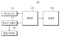
도 1을 참조하면, 일 실시예에 따른 엑스선 영상 장치는 엑스선을 발생시켜 대상체에 조사하는 엑스선 튜브(111), 대상체를 투과한 엑스선을 검출하여 전기적 신호로 변환하는 엑스선 검출기(112), 환자와 방사선사를 포함하는 사용자를 가이드하거나 사용자에게 피드백을 제공하거나 또는, 워크 플로우에 관한 정보를 제공하는 조명부(130), 엑스선 튜브(111), 엑스선 검출기(112) 및 조명부(130)의 동작을 전반적으로 제어하는 제어부(120) 및 변환된 전기적 신호를 이용하여 엑스선 영상을 생성하는 영상 처리부(140)를 포함한다.1, an X-ray imaging apparatus according to an embodiment includes an
엑스선 튜브(111)는 대상체의 특성이나 스캔 목적에 적합한 스캔 파라미터에 따라 엑스선을 발생시켜 대상체에 조사한다. 스캔 파라미터는 사용자에 의해 설정될 수도 있고, 제어부(120)가 자동으로 설정할 수도 있다.The
엑스선 검출기(112)는 엑스선 튜브(111)에서 조사되어 대상체를 투과한 엑스선을 검출하고, 검출된 엑스선에 대응되는 전기적 신호를 발생시킬 수 있다. 발생된 전기적 신호는 영상 처리부(140)로 전달된다. 영상 처리부(140)로 전달되는 전기적 신호는 디지털 신호일 수도 있고 아날로그 신호일 수도 있다. 디지털 신호로 전달되는 경우에는, 엑스선 검출기(112)에 아날로그-디지털 컨버터(ADC)를 구비하여 아날로그 형태의 전기적 신호를 디지털 형태의 전기적 신호로 변환하여 영상 처리부(140)에 전달할 수 있다.The
제어부(120)는 조명부(130)의 동작을 제어할 수 있다. 예를 들어, 조명부(130)의 점등, 소등, 점멸, 색, 디밍(dimming) 등을 제어할 수 있다. 또한, 제어부(120)는 엑스선 튜브(111)나 엑스선 검출기(112)의 동작을 제어할 수 있다. 예를 들어, 엑스선 튜브(111)의 스캔 파라미터를 자동으로 설정하는 자동 노출 제어(Auto Exposure Control)를 수행하거나, 엑스선 검출기(112)가 전기적 신호를 리드아웃(read-out)하는 동작을 제어할 수도 있다.The
제어부(120)는 전술한 제어 동작에 관한 프로그램이 저장된 메모리 및 메모리에 저장된 프로그램을 실행시킬 수 있는 프로세서를 포함할 수 있다. 또한, 제어부(120)는 단일의 메모리와 프로세서를 포함할 수도 있고, 복수의 메모리 또는 복수의 프로세서를 포함할 수도 있다. 복수의 메모리 또는 복수의 프로세서를 포함하는 경우에는, 이들 메모리와 프로세서가 하나의 칩(chip)에 집적되거나 물리적으로 동일한 모듈에 포함되는 것도 가능하고, 물리적으로 다른 모듈에 포함되는 것도 가능하다. 예를 들어, 복수의 프로세서 중 일부는 엑스선 영상 장치(100)의 워크 스테이션(105)에 포함되고, 다른 일부는 암(110)이나 갠트리(101)에 포함되는 것도 가능하다. 다시 말해, 제어부(120)를 구성하는 프로세서나 메모리의 물리적인 위치에 대해서는 제한을 두지 않는다.The
영상 처리부(140)는 엑스선 검출기(112)로부터 전달된 전기적 신호를 이용하여 대상체의 엑스선 영상을 생성한다. 엑스선 검출기(112)로부터 전달된 전기적 신호 자체도 엑스선 영상이 될 수 있기는 하나, 대상체의 내부 구조나 병변을 확인하기에는 판독성이 떨어지므로 영상 처리부(140)가 전기적 신호에 각종 처리를 수행하여 디스플레이부(151)에 표시할 수 있는 엑스선 영상을 생성할 수 있다.The
영상 처리부(140)가 수행하는 영상 처리는 전처리(pre-processing)와 후처리(post-processing)를 포함할 수 있으며, 전처리는 이득(gain) 보정, 오프셋(offset) 보정 또는 동일 감도 보정(flat field correction) 등을 포함할 수 있고, 후처리는 영상 개선 또는 영상 강화를 위한 노이즈 보정, 대조도(contrast) 보정, 선예도(sharpness) 보정 또는 밝기(brightness) 보정 등을 포함할 수 있다.The image processing performed by the
영상 처리부(140)는 전술한 처리 동작에 관한 프로그램이 저장된 메모리 및 메모리에 저장된 프로그램을 실행시킬 수 있는 프로세서를 포함할 수 있다. 또한, 영상 처리부(140)는 단일의 메모리와 프로세서를 포함할 수도 있고, 복수의 메모리 또는 복수의 프로세서를 포함할 수도 있다. 또한, 영상 처리부(140)는 제어부(120)의 메모리 또는 프로세서의 전부 또는 일부를 공유하는 것도 가능하다.The
일 실시예에 따른 엑스선 영상 장치(100)는 환자의 신체 부위 중 유방을 촬영할 수 있는 구조를 갖는다. 이하 도 2를 참조하여 설명하도록 한다.The
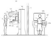
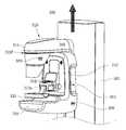
도 2를 참조하면, 유방을 촬영하는 엑스선 영상 장치(100)는 연결부(102)를 통해 갠트리(101)에 암(arm)(110)이 연결된 구조를 가지며, 갠트리(101)는 암(110)을 지지한다. 암(110)의 상부에는 엑스선 튜브(111)가 암(110)의 하부에는 엑스선 검출기(112)가 내장된다. 엑스선 튜브(111)가 내장되는 암(110)의 상부는 튜브 헤드(115)라 하고, 엑스선 검출기(112)가 내장되는 암(110)의 하부는 검출기 장착부(116)라 하기로 한다. 검출기 장착부(116)는 버키(bucky)라고도 지칭된다.2, an
엑스선 튜브 (111)와 엑스선 검출기(112)의 사이에 환자(P)의 유방(10)이 위치하면, 엑스선 튜브 (111)가 유방에 엑스선을 조사하고 엑스선 검출기(112)는 유방을 투과한 엑스선 검출하여 전기적 신호로 변환한다. 변환된 전기적 신호는 영상 처리부(140)로 전달되어 유방의 엑스선 영상을 생성하는데 사용된다.When the
도 3을 참조하면, 엑스선 튜브 (111)는 양극(111c)과 음극(111e)을 포함하는 2극 진공관으로 구현될 수 있고, 관체는 규산경질 유리 등을 재료로 하는 유리관(111a)일 수 있다. 따라서, 엑스선 튜브 (111)를 엑스선 튜브(x-ray tube)라고도 한다.3, the
음극(111e)은 필라멘트(111h)와, 전자를 집속시키는 집속 전극(111g)을 포함하며, 집속 전극(111g)은 포커싱 컵(focusing cup)이라고도 한다. 유리관(111a) 내부를 약 10mmHg 정도의 고진공 상태로 만들고 음극의 필라멘트(111h)를 고온으로 가열하여 열전자를 발생시킨다. 필라멘트(111h)의 일 예로 텅스텐 필라멘트를 사용할 수 있고 필라멘트에 연결된 전기도선(111f)에 전류를 가하여 필라멘트(111h)를 가열할 수 있다.The
양극(111c)은 주로 구리로 구성되고, 음극(111e)과 마주보는 쪽에 타겟 물질(111d)이 도포 또는 배치되며, 타겟 물질로는 크롬(Cr), 철(Fe), 코발트(Co), 니켈(Ni), 텅스텐(W), 몰리브덴(Mo), 로듐(Rh) 등의 고저항 재료들이 사용될 수 있다. 타겟 물질의 종류는 대상체의 특성에 따라 결정될 수 있다. 예를 들어, 치밀한 조직(dense tissue)을 갖는 유방을 촬영하는 경우에는 텅스텐이나 로듐을 사용하여 고에너지 엑스선을 발생시키고, 저에너지 엑스선을 발생시키고자 하는 경우에는 몰리브덴을 사용할 수 있다.The
그리고 음극(111e)과 양극(111c) 사이에 고전압을 걸어주면 열전자가 가속되어 양극의 타겟 물질(111d)에 충돌하면서 엑스선을 발생시킨다. 발생된 엑스선은 윈도우(111i)를 통해 외부로 조사되며, 윈도우의 재료로는 베릴륨(Be) 박막을 사용할 수 있다.When a high voltage is applied between the
이 때, 윈도우(111i)의 전면에는 필터(114a)를 위치시켜 특정 에너지 대역의 엑스선을 필터링할 수 있다. 필터(114a)의 재료로는 몰리브덴(Mo), 로듐(Rh), 이트륨(Y), 알루미늄(Al) 등이 사용될 수 있다. 재료마다 흡수하는 에너지 대역이 다르므로 조사하고자 하는 엑스선의 에너지 대역에 따라 적절한 필터(114a)의 재료를 선택할 수 있다. 예를 들어, 저에너지 엑스선을 흡수하기 위해서는 몰리브덴을 필터(114a)의 재료로 사용할 수 있고, 30kVp 이상의 에너지를 갖는 엑스선을 흡수하기 위해서는 알루미늄을 필터(114a)의 재료로 사용할 수 있다.At this time, the
양극(111c)은 로터(111b)에 의해 회전할 수 있으며, 양극(111c)이 회전하게 되면 고정된 경우에 비해 열 축적율이 단위 면적당 10배 이상 증대될 수 있고, 초점 크기가 감소된다.The
엑스선 튜브(111)의 음극(111e)과 양극(111c) 사이에 가해지는 전압을 관전압이라 하며, 그 크기는 파고치kvp로 표시할 수 있다. 관전압이 증가하면 열전자의 속도가 증가되고 결과적으로 타겟 물질에 충돌하여 발생되는 엑스선의 에너지(광자의 에너지)가 증가된다. 엑스선 튜브(111)에 흐르는 전류는 관전류라 하며 평균치 mA로 표시할 수 있고, 관전류가 증가하면 엑스선의 선량(엑스선 광자의 수)이 증가된다.The voltage applied between the
따라서, 관전압에 의해 엑스선의 에너지가 제어될 수 있고, 관전류 및 엑스선 노출 시간에 의해 엑스선의 선량이 제어될 수 있는바, 대상체의 종류나 특성에 따라 조사되는 엑스선의 에너지 및 세기를 제어할 수 있다.Therefore, the energy of the x-ray can be controlled by the tube voltage, and the dose of the x-ray can be controlled by the tube current and the exposure time of the x-ray, so that the energy and intensity of the x- .
조사되는 엑스선이 일정 에너지 대역을 갖는 경우, 에너지 대역은 상한과 하한에 의해 정의될 수 있다. 에너지 대역의 상한, 즉 조사되는 엑스선의 최대 에너지는 관전압의 크기에 의해 조절될 수 있고, 에너지 대역의 하한, 즉 조사되는 엑스선의 최소 에너지는 필터에 의해 조절될 수 있다. 필터를 이용하여 저에너지 대역의 엑스선을 여과시키면, 조사되는 엑스선의 평균 에너지를 높일 수 있다.If the irradiated X-ray has a constant energy band, the energy band can be defined by the upper and lower limits. The upper limit of the energy band, that is, the maximum energy of the irradiated x-ray can be controlled by the magnitude of the tube voltage, and the lower limit of the energy band, that is, the minimum energy of the irradiated x- By filtering the X-rays of the low-energy band using a filter, the average energy of the X-rays to be irradiated can be increased.
윈도우(111i)의 전면에는 콜리메이터(collimator)(114b)가 배치되어 윈도우(111i)를 통해 조사되는 엑스선의 조사 범위를 조절할 수 있고, 엑스선의 산란을 감소시킬 수 있다.A
전술한 관전압, 관전류, 엑스선 노출 시간, 타겟 물질의 종류, 필터의 종류, 양극의 회전 속도 등이 사용자 또는 제어부(120)에 의해 설정되는 스캔 파라미터가 될 수 있다.The tube voltage, the tube current, the exposure time of the X-ray, the kind of the target material, the type of the filter, the rotation speed of the anode, and the like may be the scan parameters set by the user or the
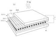
도 4를 참조하면, 엑스선 검출기(112)는 엑스선을 검출하여 전기 신호를 발생시키는 수광 소자(112-1)와 발생된 전기 신호를 읽어 내는(read-out) 독출 회로 (112-2)을 포함할 수 있다.4, the
수광 소자(112-1)로는 낮은 에너지와 적은 선량에서의 높은 해상도와 빠른 응답 시간 및 높은 동적 영역을 확보하기 위하여 단결정 반도체 물질이 사용될 수 있으며, 이 때 사용되는 단결정 반도체 물질은 Ge, CdTe, CdZnTe, GaAs 등이 있다.As the light receiving element 112-1, a single crystal semiconductor material may be used in order to secure a high resolution, a fast response time and a high dynamic range at a low energy and a small dose. The single crystal semiconductor material used here is Ge, CdTe, CdZnTe , GaAs, and the like.
수광 소자(112-1)는 고저항의 n형 반도체 기판(112b)의 하부에, 2차원 어레이 구조의 p형 반도체 기판(112c)이 접합되는 PIN 포토다이오드 형태를 형성할 수 있다.The light receiving element 112-1 can form a PIN photodiode in which a p-
CMOS(Complementary Metal Oxide Semiconductor) 공정을 이용한 독출 회로(112-2)는 2차원 어레이 구조를 형성하여, 픽셀(Px)별로 수광 소자(112-1)의p형 기판(121c)과 결합될 수 있다. 이 때, 결합 방식은 땜납(PbSn), 인듐(In) 등의 범프(bump)(112-3)를 형성한 후 reflow하고 열을 가하며 압착하는 플립칩 본딩 방식이 이용될 수 있다.The readout circuit 112-2 using a CMOS (Complementary Metal Oxide Semiconductor) process forms a two-dimensional array structure and can be combined with the p-type substrate 121c of the light receiving element 112-1 for each pixel Px . In this case, a flip chip bonding method may be used in which a bump 112-3 such as solder (PbSn) or indium (In) is formed and then reflowed, heated and pressed.
전술한 엑스선 튜브나 엑스선 검출기의 구조는 엑스선 영상 장치(100)에 적용될 수 있는 일 예시에 불과하며, 엑스선 영상 장치(100)의 실시예가 이들 구조에 한정되는 것은 아니다. 따라서, 전술한 구조 외에 다른 구조를 가질 수도 있음은 물론이다.The structure of the X-ray tube or X-ray detector described above is only an example that can be applied to the
한편, 유방(10)은 유방의 둘레를 둘러싸면서 형태를 유지시켜주는 섬유 조직, 유방 전체에 분포되는 지방 조직, 모유를 생산하는 유선 조직, 모유의 이동 통로인 유관 조직 등으로 구성된다. 이 중에서 유선 조직과 유관 조직 등 모유의 생산과 공급에 관계되는 조직을 유방의 실질 조직(fibroglandular tissue)이라 한다. 이와 같이, 유방은 연조직으로만 구성되어 있어 구성물질들 간의 감쇠 계수 차이가 크지 않기 때문에 유방을 압착하여 두께를 감소시키면 낮은 선량으로도 대조도가 높은 영상을 얻을 수 있고, 유방을 압착하면 상하 방향으로 겹쳐져 있는 물질들이 펼쳐지는 효과가 있다.On the other hand, the
다시 도 2를 참조하면, 엑스선 영상 장치(100)는 엑스선 튜브(112)와 엑스선 검출기(112) 사이에 마련되는 압착 패들(113)을 더 포함한다. 유방(10)이 검출기 장착부(116) 위에 올려지면 압착 패들(113)은 유방(10)을 압착하고, 엑스선 튜브(111)는 압착된 유방(10)에 엑스선을 조사한다. 유방(10)을 투과한 엑스선은 엑스선 검출기(112)에 의해 검출된다.Referring again to FIG. 2, the
워크 스테이션(105)에는 스캔에 의해 획득된 엑스선 영상이나 엑스선 영상 장치(100)의 제어와 관련된 화면을 표시하는 디스플레이부(105a)와 엑스선 영상 장치(100)에 대한 제어 명령을 사용자로부터 입력 받는 입력부(105b)가 마련된다. 방사선사(R)는 워크 스테이션(105)을 조작하여 스캔을 제어하고, 획득된 엑스선 영상을 확인할 수 있다. 당해 실시예에서는 스캔과 촬영은 모두 대상체에 엑스선을 투과시켜 대상체의 내부를 영상화하는 동작을 의미하는 것으로서, 이하 혼용될 수 있다.The
방사선사(R)의 불필요한 엑스선 피폭을 방지하기 위하여, 워크 스테이션(105)과 갠트리(101) 사이에 엑스선을 차단하는 보호 스크린(1)이 설치될 수 있다. 방사선사(R)는 보호 스크린(1) 밖에서는 암(110)의 위치를 제어하고 환자(P)의 자세를 설정해주고, 보호 스크린(1) 안에서는 워크 스테이션(105)을 조작하여 스캔을 제어한다. 또는, 워크 스테이션(105)과 갠트리(101)가 서로 분리된 룸에 위치하는 것도 가능하다. 이러한 워크 플로우(Work flow)는 방사선사(R)에게 과중한 작업 로드로 작용하여 부담이 될 수 있으며, 이러한 과중한 작업 로드는 결과적으로 작업의 효율성을 떨어뜨려 영상의 품질 저하를 가져올 수 있다.A
또한, 환자(P)는 유방(10)을 촬영하기 위해 상의를 탈의하고, 촬영될 유방 엑스선 영상의 종류에 따라 정해진 자세를 유지해야 한다. 긴장한 상태의 환자(P)는 촬영 진행 상황에 대한 이해도와 방사선사의 지시에 대한 순응도가 낮을 수 있고, 이는 환자(P) 본인의 불쾌감, 방사선사(R)의 정신적, 신체적 부담을 초래할 수 있다. 이 역시 결과적으로는 영상의 품질 저하를 가져올 수 있다. 이하의 실시예에서는 엑스선 영상 장치(100)에 의해 촬영되는 환자, 엑스선 영상 장치(100)를 조작하여 촬영을 진행하는 방사선사 및 엑스선 영상 장치(100)를 이용하여 진단 또는 시술을 수행하는 의사를 모두 사용자라 하기로 한다.In addition, the patient P is required to remove the image of the
일 실시예에 따른 엑스선 영상 장치(100)는 사용자에게 시각적인 상호 작용을 제공하는 조명부(130)를 더 포함한다. 조명부(130)는 환자에게 워크 플로우나 자세에 관한 정보를 제공하여 가이드하고, 방사선사에게 암(110)의 움직임에 대한 피드백을 제공할 수 있다. 당해 실시예에서, 워크 플로우(workflow)는 엑스선 촬영을 위한 복수의 단계로 구성될 수 있으며, 한 세트의 워크 플로우는 환자가 엑스선 영상 장치(100)가 위치하는 룸(검사실)에 입장한 이후부터 해당 환자에 대한 엑스선 촬영이 완료되어 퇴장하는 때까지의 과정(procedure)들을 포함할 수 있다. 한 세트의 워크 플로우에서는 적어도 한 종류의 엑스선 촬영이 수행될 수 있다.The
조명부(130)는 암(110)의 튜브 헤드(115)에 장착되는 헤드 조명(131) 및 암(110)의 손잡이(103)에 장착되는 손잡이 조명(132)을 포함할 수 있다. 헤드 조명(131)과 손잡이 조명(132)은 색, 점등, 소등 및 점멸 중 적어도 하나를 통해 사용자에게 시각적인 상호 작용을 제공할 수 있다. 시각적인 상호 작용은 정보의 제공과 피드백을 포함할 수 있다.The
헤드 조명(131) 또는 손잡이 조명(132)의 색이나 점멸을 워크 플로우를 구성하는 단계마다 다르게 나타냄으로써 사용자에게 현재 단계에 대한 정보를 제공할 수 있으며, 전체 워크 플로우에는 비상(emergency) 상황도 포함될 수 있다. 예를 들어, 기기의 고장과 같은 비상 상황이 감지되면, 헤드 조명(131) 또는 손잡이 조명(132)의 색을 붉은색으로 나타내고, 점멸의 주기를 짧게 할 수 있다.The color or blinking of the
또한, 헤드 조명(131) 또는 손잡이 조명(132)을 통해 환자(P)의 자세를 가이드하거나, 방사선사(R)의 암(110) 위치 정렬을 가이드할 수 있다.The posture of the patient P can be guided through the
헤드 조명(131)과 손잡이 조명(132)이 사용자에게 시각적인 상호 작용을 제공하는 구체적인 실시예들은 뒤에서 더 자세히 설명하도록 한다.Specific embodiments in which the
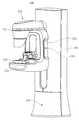
도 5는 갠트리에 장착되는 갠트리 조명을 더 포함하는 엑스선 영상 장치의 외관도이다.5 is an external view of an x-ray imaging apparatus further comprising gantry illumination mounted on a gantry.
도 5를 참조하면, 조명부(130)는 갠트리(101)에 장착되는 갠트리 조명(133)을 더 포함할 수 있다. 갠트리 조명(133)은 갠트리(101)의 하부에 장착되어 지면을 향해 광을 조사할 수 있고, 갠트리 조명(133)으로부터 조사된 광은 지면에 라인(L)을 형성할 수 있다.Referring to FIG. 5, the
갠트리 조명(133)은 지면을 향해 기울어지는 각도가 조절될 수 있는바, 이를 통해 라인(L)의 위치를 조절할 수 있다. 따라서, 갠트리 조명(133)은 적절한 위치에 라인(L)을 형성함으로써 엑스선 촬영을 위한 환자(P)의 위치를 가이드할 수 있다.The angle at which the
한편, 조명부(130)에 포함되는 헤드 조명(131), 손잡이 조명(132) 또는 갠트리 조명(133)은 반도체 레이저, He-Ne 레이저, 할로겐램프, LED램프 등 다양한 종류의 광원으로 구현될 수 있다.The
도 6은 다른 실시예에 따른 엑스선 영상 장치의 제어 블록도이고, 도 7 및 도 8은 도 6의 실시예에 따른 엑스선 영상 장치의 외관도이다.FIG. 6 is a control block diagram of an X-ray imaging apparatus according to another embodiment, and FIGS. 7 and 8 are external views of an X-ray imaging apparatus according to the embodiment of FIG.
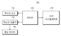
도 6을 참조하면, 다른 실시예에 따른 엑스선 영상 장치(200)는 엑스선 튜브(211), 엑스선 검출기(212), 제어부(220), 영상 처리부(240) 및 서브 디스플레이부(250)를 포함한다.6, an
엑스선 튜브(211), 엑스선 검출기(212) 및 영상 처리부(240)에 관한 설명은 전술한 실시예에 따른 엑스선 영상 장치(100)의 엑스선 튜브(111), 엑스선 검출기(112) 및 영상 처리부(140)에 관한 설명과 동일하므로, 여기서는 자세한 설명을 생략하도록 한다.The description of the
한편, 도 7의 외관도에는 도시되지 않았으나, 당해 실시예에 따른 엑스선 영상 장치(200)도 촬영된 엑스선 영상이나 엑스선 영상 장치(200)의 제어와 관련된 화면을 표시하는 디스플레이부와 엑스선 영상 장치(200)에 대한 제어 명령을 사용자로부터 입력 받는 입력부가 마련된 워크 스테이션을 포함할 수 있다.7, the
서브 디스플레이부(250)는 워크 스테이션에 마련된 디스플레이부와 별개로 마련될 수 있다. 일 예로, 도 7에 도시된 바와 같이, 암(210)에 마련된 암 디스플레이부(251)와 갠트리(201)에 마련된 갠트리 디스플레이부(252)를 포함할 수 있다.The
암 디스플레이부(251)에는 워크 플로우에 관한 정보, 환자의 자세에 관한 정보, 환자에 관한 정보 또는 암(210)에 관한 정보가 표시되거나 촬영에 의해 획득된 엑스선 영상이 표시될 수 있다.Information on the workflow, information on the attitude of the patient, information on the patient or information on the
갠트리 디스플레이부(252)에는 암 디스플레이부(251)에 표시된 정보 또는 영상과 동일한 내용이 표시될 수도 있고, 다른 내용이 표시될 수도 있다. 갠트리 디스플레이부(252)는 암(210)에 관한 정보, 특히 압착 패들(213)의 압력에 관한 정보를 표시하여 방사선사(R)가 환자(P)의 자세를 설정하는 것을 가이드할 수 있다.The
암 디스플레이부(251)와 갠트리 디스플레이부(252)는 LCD(Liquid Crystal Display), LED(Light Emission Diode), PDP(Plasma Display Panel), OLED(Organic Light Emission Diode) 등의 다양한 디스플레이 장치 중 적어도 하나로 구현될 수 있다.The
제어부(220)는 엑스선 영상 장치(200)의 동작 전반에 관한 제어를 수행할 수 있고, 서브 디스플레이부(250)에 표시되는 화면에 대한 제어를 수행할 수 있다.The
한편, 암 디스플레이부(251)는 분리 가능한 형태로 장착되어 도 8에 도시된 바와 같이, 암(210)으로부터 자유롭게 장착 및 분리되는 것도 가능하다. 생체 검사(Biopsy)를 수행하는 경우와 같이, 엑스선 영상의 촬영 후 환자(P)가 다른 장소로 이동을 해야 하는 경우, 암(210)으로부터 분리된 암 디스플레이부(251)를 들고 함께 이동하면 이동한 다른 장소에서 엑스선 영상에 관한 정보를 바로 확인할 수 있다.On the other hand, the
또한, 암 디스플레이부(251)를 스마트폰, 태블릿 PC, PDA 등과 같은 모바일 디스플레이 기기로 구현하는 것도 가능하다. 이 경우, 사용자는 모바일 디스플레이 기기에 전술한 동작을 실행할 수 있는 어플리케이션을 설치하여 암 디스플레이부(251)로 사용할 수 있다. 사용자는 엑스선 촬영을 위한 워크 플로우가 진행되는 동안은 모바일 디스플레이 기기를 암(210)에 장착하여 암 디스플레이부(251)로서 사용하고, 엑스선 촬영이 종료된 후에는 모바일 디스플레이 기기를 암(210)으로부터 분리하여 검사실 외에 다른 장소에서 사용할 수 있다.Also, the
분리 가능한 암 디스플레이부(251)는 다양한 방식에 의해 암(210)에 장착될 수 있다. 일 예로, 도 8에 도시된 바와 같이, 패들 장착부(213a)의 상단 일부를 연장하여 암 디스플레이부(251)를 지지할 수 있는 면(surface)을 형성할 수 있다. 그리고, 그의 일 영역에 홈을 형성하고, 암 디스플레이부(251)의 후면에 돌기를 형성하여 돌기가 홈에 삽입 및 분리되는 방식으로 암 디스플레이부(251)가 암(210)에 장착 및 분리될 수 있다.The detachable
다른 예로, 암 디스플레이부(251)의 후면에 자석을 부착하고, 암(210)의 일 영역에 자석을 내장하여 해당 영역에 암 디스플레이부(251)를 장착하는 것도 가능하다.As another example, it is also possible to attach a magnet to the rear surface of the
또 다른 예로, 암 디스플레이부(251)의 각도가 조절되도록 장착하여 사용자가 편의에 따라 암 디스플레이부(251)의 각도를 조절할 수 있도록 하는 것도 가능하다.As another example, the angle of the
도 9는 또 다른 실시예에 따른 엑스선 영상 장치의 제어 블록도이고, 도 10은 도 9의 실시예에 따른 엑스선 영상 장치의 외관도이다.FIG. 9 is a control block diagram of an X-ray imaging apparatus according to another embodiment, and FIG. 10 is an external view of an X-ray imaging apparatus according to the embodiment of FIG.
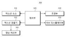
도 9를 참조하면, 또 다른 실시예에 따른 엑스선 영상 장치(300)는 엑스선 튜브(311), 엑스선 검출기(312), 제어부(320), 조명부(330), 영상 처리부(340) 및 서브 디스플레이부(350)를 포함한다.9, an
엑스선 튜브(311), 엑스선 검출기(312) 및 영상 처리부(340)는 전술한 도 1의 실시예에서 설명한 바와 같으므로, 여기서는 설명을 생략한다.The
조명부(330)는 전술한 도 1의 실시예에 따른 조명부(110)와 동일하고, 서브 디스플레이부(350)는 전술한 도 6의 실시예에 따른 서브 디스플레이부(250)와 동일하다. 즉, 당해 실시예에 따른 엑스선 영상 장치(300)는 도 10에 도시된 바와 같이, 환자와 방사선사를 포함하는 사용자를 가이드하고, 워크 플로우에 관한 정보를 제공하는 조명부(330)와 스캔 프로세스에 관한 정보, 환자의 자세에 관한 정보, 환자에 관한 정보 또는 암(210)에 관한 정보가 표시되거나 획득된 엑스선 영상이 표시되는 서브 디스플레이부(350)를 모두 포함한다.The
당해 실시예에 따른 엑스선 영상 장치(300)에 의하면, 사용자에게 스캔에 관한 정보나 시각적인 상호작용 또는 피드백을 제공함에 있어서, 조명과 디스플레이를 함께 사용함으로써 그 효율성을 향상시킬 수 있다.According to the
한편, 도 10의 외관도에는 도시되지 않았으나, 당해 실시예에 따른 엑스선 영상 장치(200)도 촬영된 엑스선 영상이나 엑스선 영상 장치(200)의 제어와 관련된 화면을 표시하는 디스플레이부와 엑스선 영상 장치(200)에 대한 제어 명령을 사용자로부터 입력 받는 입력부가 마련된 워크 스테이션을 포함할 수 있다.10, the
도 11은 음향 출력부를 더 포함하는 엑스선 영상 장치의 제어 블록도이고, 도 12는 도 11의 실시예에 따른 엑스선 영상 장치의 외관도이다.FIG. 11 is a control block diagram of an X-ray imaging apparatus further including an acoustic output unit, and FIG. 12 is an external view of an X-ray imaging apparatus according to the embodiment of FIG.
도 11을 참조하면, 엑스선 영상 장치(300)는 조명부(330)와 서브 디스플레이부(350) 뿐만 아니라 음향 출력부(360)를 더 포함할 수 있다. 음향 출력부(360)는 사용자에게 스캔에 관한 정보나 상호 작용 또는 피드백을 시각적으로 제공하는 것뿐만 아니라, 청각적으로도 제공할 수 있다.Referring to FIG. 11, the
도 12에 도시된 바와 같이, 음향 출력부(360)는 스피커로 구현될 수 있으며, 암(310)의 일부에 하나 이상 마련될 수 있다. 또는, 암(310)에 직접 마련되지 않고 압착 패들(313) 또는 패들 장착부(313a)에 마련되는 것도 가능하다. 또는, 음향 출력부(360)가 갠트리(301)에 마련되는 것도 가능하며, 암(310)과 갠트리(301) 모두에 마련되는 것도 가능하다. 엑스선 촬영을 위한 워크 플로우 중에 사용자가 청취할 수 있는 위치이기만 하면 되고, 음향 출력부(360)가 마련되는 구체적인 위치나 크기에 대해서는 제한을 두지 않는다.As shown in FIG. 12, the
당해 실시예와 같이, 스캔에 관한 정보나 상호 작용 또는 피드백을 시각적으로도 제공하고 청각적으로도 제공하면 방사선사의 작업 로드를 더 줄여줄 수 있고, 더 많은 정보를 더 효과적으로 제공할 수 있다.As with the present embodiment, providing information about the scan, interactivity or feedback visually and also audibly can further reduce the radiologist's workload and provide more information more effectively.
이하, 도 11 및 도 12의 실시예에 기초하여 엑스선 영상 장치(300)를 이용한 구체적인 워크 플로우를 설명하도록 한다.Hereinafter, a specific workflow using the
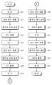
도 13은 유방에 대한 엑스선 영상을 촬영하는 경우에 적용될 수 있는 전체 워크 플로우의 일 예시를 나타낸 순서도이고, 도 14 내지 도 28은 워크 플로우를 구성하는 각각의 단계에서 엑스선 영상 장치(300)가 시각 또는 청각적으로 환자 또는 방사선사에게 제공하는 정보 또는 피드백을 나타낸 도면이다.FIG. 13 is a flowchart showing an example of an entire work flow applicable to the case of photographing an X-ray image to the breast, and FIGS. 14 to 28 illustrate a case where the X- Or auditory information or feedback to a patient or radiologist.
도 13을 참조하면, 엑스선 영상 장치(300)가 위치하는 룸에 환자가 입장하면(411), 환자는 유방을 검출기 장착부(316) 위에 올려놓을 수 있는 위치에 선다.Referring to FIG. 13, when the patient enters the room where the
환자가 적절한 위치에 서면 방사선사가 환자의 자세를 잡아주고 유방을 압착 패들(313)로 압착시킨 후에 촬영을 진행한다. 이 때, 촬영의 종류에 따라 환자의 자세가 달라질 수 있다. 예를 들어, 유방의 촬영은 내외사방향 (Mediolateral oblique projection: MLO) 촬영과 상하방향 (Craniocaudal: CC) 촬영을 포함할 수 있다. 당해 예시에서는 우측 유방과 좌측 유방에 대해 MLO 촬영과 CC 촬영을 각각 수행하는 것으로 한다.When the patient is in the proper position, the radiographer catches the patient's posture and presses the breast with the crimping
우측 유방에 대한 CC 촬영인 RCC(Right Craniocaudal) 촬영을 위해 암(310)의 위치를 정렬하고(412), 암(310)의 위치가 정렬되면, 환자의 유방을 검출기 장착부(316)와 압착 패들(313) 사이에 위치시킨 후 압착시키고 환자의 팔, 고개 등을 촬영에 적합한 지점에 위치시켜 자세를 잡아준다(413). 환자의 자세가 고정되면, RCC 촬영을 수행하고(414), 그 다음 촬영을 진행하기 전까지 대기한다(415).The position of the
그리고, 좌측 유방에 대한 CC 촬영인 LCC 촬영을 위해 암의 위치 정렬(416), 환자의 자세 설정(417), LCC 촬영(418)을 수행하고, 그 다음 촬영을 진행하기 전까지 대기한다(419).The
그리고, 우측 유방에 대한 MLO 촬영인 RMLO 촬영을 위해 암의 위치 정렬(420), 환자의 자세 설정(421), RMLO 촬영(422)을 수행하고, 그 다음 촬영을 진행하기 전까지 대기한다(423).The
그리고, 좌측 유방에 대한 MLO 촬영인 LMLO 촬영을 위해 암의 위치 정렬(424), 환자의 자세 설정(425), LMLO 촬영(426)을 수행하고, 퇴장한다(427).Then, the position alignment 424 of the arm, the posture setting 425 of the patient, and the
이하, 도 13의 각 단계마다 해당 단계에 관한 도면을 참조하여 구체적으로 설명한다.Hereinafter, each step of FIG. 13 will be described in detail with reference to the drawings related to the step.
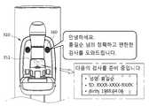
도 14 및 도 15는 환자의 입장 시에 제공되는 시청각적인 정보를 나타내는 도면이다.14 and 15 are diagrams showing audiovisual information provided at the time of entry of a patient.
촬영된 영상은 환자의 성명, 해당 환자에 대해 미리 설정된 ID, 생년월일 등을 포함하는 환자 데이터를 태그로 하여 저장되고, 저장된 영상은 환자에 대한 진단이나 치료에 사용된다. 따라서, 촬영 전에 환자의 신원 정보를 파악하는 것이 중요하다. 이를 위해, 암 디스플레이부(351)에 도 14에 도시된 바와 같은 신원 정보 확인을 위한 화면을 표시할 수 있고, 음향 출력부(360)를 통해 환자 데이터를 포함하는 안내 음성을 출력할 수 있다. 룸에 입장한 환자는 암 디스플레이부(361)에 표시된 환자 데이터(이름, ID, 생년월일) 또는 안내 음성에 포함된 환자 데이터(이름)를 자신의 신원 정보와 비교하고, 불일치하는 부분이 있으면 방사선사에게 이를 알림으로써 해당 환자의 영상이 다른 환자의 진단 또는 치료에 사용되는 것을 방지할 수 있다.The photographed image is stored with the patient data including the patient's name, the ID set in advance for the patient, the date of birth, etc., and the stored image is used for diagnosing or treating the patient. Therefore, it is important to identify the patient's identity before shooting. To this end, a screen for confirming the identity information as shown in FIG. 14 can be displayed on the
환자의 신원 정보가 환자 데이터와 일치하면, 촬영을 위한 과정이 시작된다. 먼저, 암(310)의 위치를 환자의 유방 위치에 맞게 조절할 수 있도록 환자가 암(310)에 밀착할 수 있는 위치에 서야 한다. 이를 위해, 도 15에 도시된 바와 같이, 갠트리 조명부(333)가 환자가 서야 하는 위치에 라인(L)을 형성하고, 음향 출력부(360)에서는 환자의 위치를 가이드하는 음성 정보가 출력되고, 동일 내용의 텍스트가 암 디스플레이부(351)에 표시될 수 있다.If the patient ' s identity information matches the patient data, the process for imaging begins. First, the patient must be in a position where the
한편, 경우에 따라서는 암(310)의 위치 정렬이 끝난 이후에 환자가 암(310)에 밀착하는 것도 가능한 바, 도 15의 예시에 따른 정보의 제공이 암(310)이 위치 정렬 이후에 이루어지는 것도 가능함은 물론이다.In some cases, it is possible for the patient to be in close contact with the
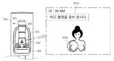
도 16은 RCC 촬영을 위해 사용자에게 제공되는 정보를 나타내는 도면이고, 도 17은 RCC 촬영을 위해 정렬되는 암의 위치와 사용자에게 제공되는 시각적인 피드백을 나타내는 도면이다.FIG. 16 is a view showing information provided to the user for RCC photographing, and FIG. 17 is a diagram showing the position of the arm arranged for RCC photographing and visual feedback provided to the user.
환자에게 앞으로 진행될 촬영에 대한 정보를 제공함으로써 환자가 느낄 수 있는 불안함을 감소시킬 수 있다. 도 16에 도시된 바와 같이, 암 디스플레이부(351)에 현재 단계에서 진행될 촬영의 종류에 관한 정보를 텍스트(351a)와 그림(351b)으로 표시함으로써 촬영에 대한 환자의 이해도를 높일 수 있고, 환자가 미리 준비를 할 수 있도록 한다. 또한, 방사선사는 촬영 진행 단계를 확인할 수 있다.By providing the patient with information about the future imaging, it is possible to reduce the patient's anxiety. As shown in Fig. 16, by displaying information about the kind of photographing to be performed at the current stage in the
암(310)의 위치 정렬을 위해, 사용자가 암(310)의 이동에 필요한 양만큼의 외력을, 원하는 방향으로 직접 가하여 암(310)을 이동시키는 것도 가능하나, 도 17에 도시된 바와 같이, 암(310)의 적어도 일 측에 마련된 입력부(309)를 조작하여 자동으로 암(310)을 이동시키는 것도 가능하다. 또한, 입력부(309)는 암(310)의 상부와 하부에 각각 마련되어 사용자의 편의에 따라 상부에 위치하는 입력부(309)와 하부에 위치하는 입력부 (309)를 선택적으로 조작하도록 할 수 있다. 입력부(309)는 레버 형태, 버튼 형태 또는 죠그 셔틀(jog shuttle) 형태로 구현될 수 있고, 이들이 조합된 형태로 구현되는 것도 가능하다. 도 17의 구조나 전술한 설명은 엑스선 영상 장치(300)에 적용될 수 있는 예시에 불과하고, 엑스선 영상 장치(300)의 실시예에서는 암(310)의 이동에 관한 명령을 입력 받는 입력부(309)의 형태, 구조, 위치 및 개수에 대해 제한을 두지 않는다.It is also possible to move the
암(310)을 자동으로 이동시키기 위해, 동력을 발생시키기 위한 모터와 발생된 동력을 암(310)에 전달하는 기어 등의 구동 장치들이 갠트리(301)의 내부에 마련될 수 있다. 암(310)이 자동으로 이동하면, 사용자가 힘을 들이지 않고도 무거운 암(310)을 이동시킬 수 있으므로, 사용자의 작업 로드를 줄여줄 수 있다.In order to automatically move the
CC 촬영은 중앙, 유륜하(subareolar)와 유방 내측을 진단하기 위한 촬영이다. 따라서, RCC 촬영을 위한 암(310)의 위치 정렬 시에는, 암(310)의 좌우 회전 각도는 회전축과 0도를 이루도록 하고, 암(310)의 상하 방향 위치는 환자의 유방 위치에 맞춘다. 암(310)을 정면에서 바라봤을 때 상하방향을 향하는 축을 회전축이라 한다.CC imaging is used to diagnose the central, subareolar, and mammary canal. Therefore, when aligning the
방사선사는 암(310)을 상측 방향으로 이동시키기 위해 입력부(309)를 조작할 수 있다. 도 17의 예시에 따르면, 입력부(309)의 중앙에 마련된 레버를 상측으로 밀어 올릴 수 있다.The radiographer may manipulate the
방사선사의 입력부 (309) 조작을 통해 암(310)을 상측으로 이동시키기 위한 명령이 입력된 경우, 도 17에 도시된 바와 같이, 헤드 조명(331) 중 정면 헤드 조명(331F)이 점멸되면서 방사선사에게 입력한 명령에 대한 피드백을 줄 수 있다. 또는, 정면 헤드 조명(331F)의 색이 달라지거나, 소등 상태에서 점등 상태로 바뀌는 것도 가능하다. 방사선사는 이와 같은 정면 헤드 조명(331F)의 변화를 보고 자신이 입력한 명령을 확인할 수 있다. 방사선사가 원래 의도한 명령이 암(310)의 상측 이동이 맞는 경우에는, 명령을 확정할 수 있다. 확정을 위해 해당 조작을 다시 한 번 반복할 수도 있고, 명령 확정을 위해 할당된 또 다른 조작을 수행할 수도 있다. 또는, 미리 정해진 기준 시간 내에 아무런 추가 명령이 입력되지 않으면 명령이 확정되는 것도 가능하다.When a command for moving the
명령이 확정되면, 암(310)은 상측으로 이동하고 원하는 위치에 도달하면 방사선사가 이동 정지를 위한 조작을 수행할 수 있다.When the command is determined, the
한편, 암(310)이 이동하는 동안에는, 이동량에 대한 정량적인 정보가 서브 디스플레이부(351,352)에 표시될 수도 있다. 당해 예시와 같이 암(310)이 상하 방향으로 이동하는 경우에는 실시간으로 그 이동 거리가 표시될 수 있다.Meanwhile, while the
도 18은 RCC 촬영을 위해 환자의 자세를 설정하는 동안 사용자에게 제공되는 시각 및 청각적인 정보를 나타내는 도면이다.18 is a diagram showing visual and auditory information provided to a user while setting a patient's posture for RCC photographing.
RCC 촬영을 위한 암(310)의 위치 설정이 완료되면, 환자의 자세를 설정한다(413). 방사선사는 환자의 유방이 압착 패들(313)과 검출기 장착부(316) 사이에 위치한 상태에서, 환자의 머리를 검사 측 반대 방향 즉, 좌측으로 돌리고, 흉부가 검출기 장착부(316)의 단부에 닿도록 밀착시킨다.When the positioning of the
그리고, 환자가 좌측 팔로 암(310)의 좌측 손잡이(303L)를 잡을 수 있도록, 도 18에 도시된 바와 같이, 좌측 손잡이(303L)에 마련된 손잡이 조명(332L)을 점등 또는 점멸시키거나 색을 변화시킴으로써 환자의 파지를 가이드할 수 있다. 이와 함께, 음향 출력부(360)에서 환자의 손잡이(303L) 파지 및 자세 유지를 가이드하는 음성 정보를 출력할 수 있다.18, the
환자의 자세 설정이 완료되면, 방사선사는 압착 패들(313)을 하강시켜 유방(10)을 압착한다. 이 때, 압착 패들(313)이 유방(10)에 가하는 압력은 암 디스플레이부(351) 및 갠트리 디스플레이부(352) 중 적어도 하나에 표시될 수 있다. 예를 들어, 방사선사가 풋 페달(foot pedal)을 발로 조작하면서 압착 패들(313)을 하강시키는 경우에는 갠트리 디스플레이부(352)에 표시된 압력의 크기를 확인하고 압착 패들(313)의 하강 위치를 조절할 수 있다.When the posture setting of the patient is completed, the radiator descends the
환자의 자세 설정이 완료되면, 방사선사는 워크 스테이션으로 이동하고, 워크 스테이션에 마련된 입력부를 조작하여 RCC 촬영을 위한 엑스선의 조사 및 검출을 실행시킬 수 있다.When the posture setting of the patient is completed, the radiographer moves to the work station and can operate the input unit provided in the work station to execute the irradiation and detection of the X-ray for RCC photographing.
도 19는 RCC 촬영이 진행되는 동안 환자에게 제공되는 시각적인 정보를 나타내는 도면이다.19 is a diagram showing visual information provided to the patient during the RCC photographing.
도 19를 참조하면, RCC 촬영이 진행되는 동안은 암 디스플레이부(351)는 현재 암(310)의 상태에 관한 정보, 예를 들어, 압착 패들(313)의 압력, 압착 두께, 암(310)의 회전 각도 등을 나타내는 정보가 포함된 윈도우(351c)를 더 표시할 수 있다. 또한, RCC 촬영의 전체 시간과 경과한 시간의 비율을 실시간으로 나타내는 바(bar, 351d)를 더 표시할 수도 있다.19, during the RCC photographing, the
그리고, 음향 출력부(360)는 현재 촬영 중이므로 자세 유지가 필요하다는 음성 정보를 출력함으로써, 현재 진행 상황에 대한 정보를 환자에게 알려주고 환자의 자세 유지를 다시 한 번 가이드할 수 있다. 환자의 자세가 암 디스플레이부(351)를 보기 어려운 자세인 경우라도 음향 출력부(360)를 통해 정보를 얻을 수 있다.Then, the
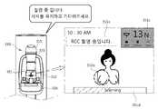
도 20은 다음 촬영을 위한 대기 중에 환자에게 제공되는 시각 및 청각적인 정보를 나타내는 도면이다.FIG. 20 is a diagram showing visual and auditory information provided to the patient in the air for the next photographing.
RCC 촬영이 종료되면, 환자는 그 다음 촬영인 LCC 촬영을 위해 대기한다(415).When the RCC photographing is finished, the patient waits for the next LCC photographing (415).
RCC 촬영이 종료되면, 음향 출력부(360)가 음성 정보를 출력하여 환자에게 촬영이 종료되었음을 알려줄 수 있다. 방사선사가 압착 패들(313)을 상승시켜 압착을 풀어주면, 암 디스플레이부(351)는 다음 촬영이 LCC 촬영이라는 정보를 제공하고 대기를 요청하는 텍스트(351e)를 표시할 수 있다. 또한, 다음 촬영을 위한 준비, 예를 들어, 암(310)의 위치 정렬이 시작될 때까지 남은 시간을 시각적으로 나타내는 바(351f)를 더 표시할 수 있다.When the RCC photographing is completed, the
LCC 촬영은 환자의 좌측 유방에 대해 수행되는 CC 촬영이므로, 촬영 대상이 환자의 좌측 유방이라는 점 및 이로부터 파생되는 몇 가지 차이점을 제외하고는 암의 위치 정렬(416), 환자의 자세 설정(417) 및 LCC 촬영(418)은 전술한 단계들 412, 413 및 414와 유사하다. 이하, 차이가 있는 부분에 대해서만 설명하도록 한다. Since the LCC photographing is the CC photographing performed on the left breast of the patient, the
도 21은 LCC 촬영을 위해 환자의 자세를 설정하는 동안 사용자에게 제공되는 시각 및 청각적인 정보를 나타내는 도면이다.21 is a diagram showing visual and auditory information provided to a user while setting a patient's posture for LCC photographing.
LCC 촬영을 위한 암의 위치가 정렬되면(416), 방사선사는 환자의 자세를 설정한다(417). 방사선사는 환자의 유방이 압착 패들(313)과 검출기 장착부(315) 사이에 위치한 상태에서, 환자의 머리를 검사 측 반대 방향 즉, 우측으로 돌리고, 흉부가 검출기 장착부(315)의 단부에 닿도록 밀착시킨다.When the position of the arm for LCC imaging is aligned (416), the radiologist sets the patient's posture (417). The radiologist inserts the patient's breast in the opposite direction to the examination side in the state where the breast of the patient is positioned between the
그리고, 환자가 우측 팔로 암(310)의 우측 손잡이(303R)를 잡을 수 있도록, 도 21에 도시된 바와 같이, 우측 손잡이(303R)에 마련된 손잡이 조명(332R)을 점등, 소등 또는 점멸 시키거나, 그 색을 변화시킴으로써 환자의 파지를 가이드할 수 있다. 이와 함께, 음향 출력부(360)에서 음성 정보를 출력하여 환자의 자세 유지를 가이드할 수 있다.21, the
환자의 자세 설정이 완료되면, 방사선사는 압착 패들(313)을 하강시켜 유방(10)을 압착한다.When the posture setting of the patient is completed, the radiator descends the
MLO 촬영은 엑스선 검출기(312)가 유방의 하외측(inferolateral)에 위치하고, 엑스선이 유방의 상내측에서 하외측을 향하여 조사되는 촬영이다. 상기 도 13의 예시에 따라 우측 유방에 대한 MLO 촬영(RMLO 촬영)과 좌측 유방에 대한 MLO 촬영(LMLO 촬영)을 모두 수행하는 경우를 예로 들어 설명한다.The MLO photographing is a photograph in which the
도 22는 RMLO 촬영을 위해 정렬되는 암의 위치와 사용자에게 제공되는 시각적인 피드백을 나타내는 도면이고, 도 23은 LMLO 촬영을 위해 정렬되는 암의 위치와 사용자에게 제공되는 시각적인 피드백을 나타내는 도면이다.FIG. 22 is a diagram showing the position of the arm to be aligned for RMLO imaging and the visual feedback provided to the user, and FIG. 23 is a diagram showing the position of the arm to be aligned for LMLO imaging and the visual feedback provided to the user.
전술한 바와 같이, MLO 촬영은 유방의 상내측에서 하외측을 향하여 엑스선을 조사하기 때문에, RMLO 촬영의 경우에는 도 22에 도시된 바와 같이, 암(310)이 회전축을 기준으로 좌측으로 회전해야한다. 환자의 체격에 따라 회전 각도는 40도 내지 70도의 범위에서 선택할 수 있다. 당해 실시예에서의 모든 방향은 환자를 기준으로 한다. 따라서, 환자의 유방 위치도 환자를 기준으로 결정되고, 암(310)의 상,하,좌,우도 암(310)을 바라보는 환자를 기준으로 결정된다.As described above, since the MLO radiography radiates X-rays from the inside to the outside of the breast, in the case of the RMLO radiography, the
RMLO 촬영을 위해 암(310)의 위치를 정렬한다(420). 이를 위해, 방사선사가 입력부(309) 조작을 통해 암(310)을 좌측으로 회전시키기 위한 명령을 입력할 수 있다. 도 22의 예시에 따르면, 입력부(309)의 좌측 버튼을 가압함으로써 해당 명령을 입력할 수 있다. 방사선사의 명령이 입력되면, 도 22에 도시된 바와 같이, 헤드 조명(331) 중 좌측 헤드 조명(331L)을 점등, 소등 또는 점멸시키거나 그 색을 변화시킴으로써 방사선사에게 입력한 명령에 대한 피드백을 줄 수 있다. 방사선사는 좌측 헤드 조명(331L)을 보고 자신이 입력한 명령을 확인할 수 있다. 방사선사가 원래 의도한 명령이 암(310)의 좌측 회전이 맞는 경우에는, 명령을 확정할 수 있다. 확정을 위해 해당 조작을 다시 한 번 반복할 수도 있고, 명령 확정을 위해 할당된 또 다른 조작을 수행할 수도 있다. 또는, 미리 정해진 기준 시간 내에 아무런 추가 명령이 입력되지 않으면 명령이 확정되는 것도 가능하다.The position of the
명령이 확정되면, 암(310)은 좌측으로 회전하고 원하는 회전 각도에 도달하면 방사선사가 이동 정지를 위한 조작을 수행할 수 있다.When the command is confirmed, the
RMLO 촬영을 위한 암(310)의 위치 정렬이 완료되면, 환자의 자세를 설정한다(421). 환자는 우측 팔로 우측 손잡이(303R)를 잡는다. 이를 가이드하기 위해 상기 도 21에 도시된 바와 같이 우측 손잡이(303R)에 마련된 손잡이 조명(332R)이 점등, 소등 또는 점멸되거나 그 색이 변함으로써 환자의 파지를 유도할 수 있다. 이와 함께, 음향 출력부(360)에서 음성 정보를 출력하여 환자의 파지 및 자세 유지를 가이드할 수 있다.When alignment of the
환자의 자세 설정이 완료되면, 방사선사는 워크 스테이션으로 이동하고, 워크 스테이션에 마련된 입력부를 조작하여 RMLO 촬영(422)을 위한 엑스선의 조사 및 검출을 실행시킨다.When the posture setting of the patient is completed, the radiologist moves to the work station and operates the input unit provided in the workstation to execute the irradiation and detection of the X-ray for the
그리고, RMLO 촬영이 진행되는 동안이나 RMLO 촬영이 종료되고 그 다음 촬영을 대기하는 동안에는 상기 도 19및 도 20에 도시된 바와 같이 현재 진행 상황에 대한 시각적인 정보를 환자에게 제공할 수 있다.19 and 20, it is possible to provide the patient with visual information of the current progress while the RMLO imaging is being performed or the RMLO imaging is completed and the next imaging is being awaited.
LMLO 촬영을 위해 암(310)의 위치를 정렬한다(420). LMLO 촬영의 경우에는 도 23에 도시된 바와 같이, 암(310)이 회전축을 기준으로 우측으로 회전해야한다. 환자의 체격에 따라 회전 각도는 40도 내지 70도의 범위에서 선택할 수 있다.The position of the
이를 위해, 방사선사가 입력부(309) 조작을 통해 암(310)을 우측으로 회전시키기 위한 명령을 입력할 수 있다. 도 23의 예시에 따르면, 입력부(309)의 우측 버튼을 가압함으로써 해당 명령을 입력할 수 있다. 방사선사의 명령이 입력되면, 도 23에 도시된 바와 같이, 헤드 조명(331) 중 우측 헤드 조명(331R)을 점등, 소등 또는 점멸시키거나 그 색을 변화시킴으로써 방사선사에게 입력한 명령에 대한 피드백을 줄 수 있다. 방사선사는 우측 헤드 조명(331R)을 보고 자신이 입력한 명령을 확인할 수 있다. 방사선사가 원래 의도한 명령이 암(310)의 우측 회전이 맞는 경우에는, 명령을 확정할 수 있다. 확정을 위해 해당 조작을 다시 한 번 반복할 수도 있고, 명령 확정을 위해 할당된 또 다른 조작을 수행할 수도 있다. 또는, 미리 정해진 기준 시간 내에 아무런 추가 명령이 입력되지 않으면 명령이 확정되는 것도 가능하다.For this purpose, the radiologist may input a command to rotate the
명령이 확정되면, 암(310)은 우측으로 회전하고 원하는 회전 각도에 도달하면 방사선사가 이동 정지를 위한 조작을 수행할 수 있다.When the command is confirmed, the
LMLO 촬영을 위한 암(310)의 위치 정렬이 완료되면, 환자의 자세를 설정한다(421). 환자는 좌측 팔로 좌측 손잡이(303L)를 잡는다. 이를 가이드하기 위해 상기 도 18에 도시된 바와 같이 좌측 손잡이(303L)에 마련된 손잡이 조명(332L)을 점등, 소등 또는 점멸시키거나 그 색을 변화시킴으로써 환자의 파지를 가이드할 수 있다. 이와 함께, 음향 출력부(360)에서 음성 정보를 출력하여 환자의 파지 및 자세 유지를 가이드할 수 있다.When alignment of the
환자의 자세 설정이 완료되면, 방사선사는 워크 스테이션으로 이동하고, 워크 스테이션에 마련된 입력부를 조작하여 LMLO 촬영(426)을 위한 엑스선의 조사 및 검출을 실행시킨다.When the posture setting of the patient is completed, the radiologist moves to the work station and operates the input unit provided in the workstation to execute the irradiation and detection of the X-ray for the LMLO imaging (426).
그리고, LMLO 촬영이 진행되는 동안에는 상기 도 19에 도시된 바와 같이 현재 진행 상황에 대한 시각적인 정보를 환자에게 제공할 수 있다.During the LMLO photographing, visual information on the current progress can be provided to the patient as shown in FIG.
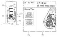
도 24는 모든 엑스선 촬영이 종료된 이후에 환자에게 제공되는 시각 및 청각적인 정보를 나타내는 도면이다.24 is a diagram showing visual and auditory information provided to a patient after all x-ray radiography is completed.
LMLO 촬영까지 종료되면, 도 24에 도시된 바와 같이, 모든 촬영의 종료를 알리고 환자의 퇴장을 안내하는 텍스트가 포함된 화면(351h)이 암 디스플레이부(351)에 표시될 수 있다. 또한, 같은 내용의 음성 정보가 음향 출력부(360)를 통해 출력되는 것도 가능하다.When the LMLO imaging is finished, a
전술한 예시에서는 환자의 유방에 대해 RCC, LCC, RMLO 및 LMLO 촬영을 수행하는 것으로 하였으나, 이는 엑스선 영상 장치(100,200,300)의 실시예에 적용될 수 있는 예시에 불과하며 이 외에도 다양한 촬영 방식이 적용될 수 있다. 예를 들어, 90도 내외방향(Mediolateral) 촬영, 90도 외내방향(lateromedial) 촬영, 30도 사방향(oblique) 촬영, Eklund 압박 촬영 등 유방에 적용될 수 있는 다양한 촬영 방식을 수행할 수 있으며, 각각의 촬영 방식에 따라 서브 디스플레이부(350), 조명부(330) 및 음향 출력부(360)를 통해 시청각적인 정보 또는 피드백을 출력할 수 있다.In the above example, RCC, LCC, RMLO, and LMLO imaging is performed on the breast of the patient, but this is only an example that can be applied to the embodiments of the
서브 디스플레이부(350), 조명부(330) 및 음향 출력부(360)는 제어부(320)에 의해 제어될 수 있다. 이를 위해, 제어부(320)는 전체 워크 플로우에 있어서, 현재의 단계를 판단할 수 있다. 제어부(320)의 판단은 사용자의 입력에 기초한 것일 수도 있고, 다른 구성요소의 동작에 기초한 것일 수도 있다. 예를 들어, 사용자가 엑스선 촬영의 시작 및 종료를 위한 명령을 입력하면, 입력된 명령에 기초하여 환자의 입장 및 퇴장을 가이드할 수 있도록 서브 디스플레이부(350), 조명부(330) 및 음향 출력부(360) 중 적어도 하나를 제어할 수 있다.The
또는, 미리 정해진 시퀀스가 모두 수행되면, 상기 도 13의 예시의 경우에는 LMLO 촬영이 완료되면, 엑스선 촬영이 모두 종료된 것으로 판단하여 환자의 퇴장을 가이드할 수 있다.Alternatively, when the predetermined sequence is all performed, in the case of the example of FIG. 13, when the LMLO imaging is completed, it is determined that the X-ray imaging is completed and the patient can be guided to the exit.
또한, 촬영의 종류마다 환자의 자세 설정과 촬영 중에 그에 맞는 정보를 제공하기 위해, 제어부(320)는 그 전단계에서 정렬된 암(310)의 위치에 기초하여 현재 단계에서의 촬영의 종류를 판단할 수도 있고, 미리 정해진 시퀀스에 기초하여 현재 단계에서의 촬영의 종류를 판단할 수 있다. 또한, 암(310)의 위치가 확정되어 더 이상 이동하지 않으면, 암(310)의 위치 정렬이 완료되고 환자의 자세 설정이 시작됨을 판단할 수 있다. 또한, 엑스선이 조사되면 촬영이 시작된 것으로 판단하여 현재 촬영 중임을 알리는 정보를 제공할 수 있고, 엑스선의 조사가 멈추면 하나의 촬영이 종료된 것으로 판단하여 그 다음 촬영의 대기 또는 퇴장을 가이드하는 정보를 제공할 수 있다.In addition, in order to provide the attitude setting of the patient and the corresponding information during shooting for each type of shooting, the
전술한 예시는 제어부(320)가 현재의 단계를 판단할 수 있는 다양한 방식 중 몇 가지를 예로 든 것에 불과하며, 엑스선 영상 장치(300)의 실시예가 이에 한정되는 것은 아니다. 따라서, 상기 예시들 외에도 다양한 방식에 의해 현재의 단계를 판단하고, 그에 따른 제어를 수행할 수 있다.The above-described example is merely an example of various ways in which the
한편, 촬영을 통해 획득한 영상은 워크 스테이션에 마련된 디스플레이부에 표시된다. 또한, 서브 디스플레이부(350)에 표시되는 것도 가능한바, 이하 서브 디스플레이부(350)에 촬영된 영상이 표시되는 예시를 구체적으로 설명한다.On the other hand, the image obtained through photographing is displayed on the display unit provided in the workstation. An example in which the
도 25는 암 디스플레이부에 촬영된 유방 영상이 표시되는 예시를 나타낸 도면이고, 도 26은 사용자가 암 디스플레이부를 조작하는 예시를 나타낸 도면이다.FIG. 25 is a diagram showing an example in which a breast image photographed on an arm display unit is displayed, and FIG. 26 is an illustration showing an example in which a user operates an arm display unit.
도 25에 도시된 바와 같이, 암 디스플레이부(351)는 촬영된 유방 영상(351k)을 표시할 수 있고, 이와 함께 이전에 촬영된 환자의 유방 영상(351j)을 표시할 수 있다. 방사선사는 현재 영상과 이전 영상을 비교하여 환자의 상태, 병변의 위치, 재촬영의 필요 여부 등을 확인할 수 있다.As shown in Fig. 25, the
암 디스플레이부(351)를 터치 스크린으로 구현하면 사용자는 암 디스플레이부(351)의 화면을 조작하여 명령을 입력할 수 있다. 예를 들어, 도 26에 도시된 바와 같이, 두 손가락(F)으로 화면의 두 지점을 터치한 후 손가락 사이의 간격을 좁히는 방식으로 화면을 줌인(zoom in)시키거나, 다시 손가락 사이의 간격을 넓히는 방식으로 화면을 줌아웃(zoom out)시킬 수 있다. 또는, 화면에 손가락을 터치한 후 상하 방향으로 드래그(drag)하는 방식으로 패닝(panning)시킬 수도 있다. 이 외에도 다양한 터치 입력에 의해 화면에 표시된 영상을 조작할 수 있다.If the
도 27은 촬영된 영상을 통해 타겟의 위치를 확인할 수 있는 예시를 나타낸 도면이고, 도 28은 타겟의 위치 확인 후에 생체 검사를 가이드하는 예시를 나타낸 도면이다.FIG. 27 is a view showing an example where the position of the target can be confirmed through the photographed image, and FIG. 28 is a diagram showing an example of guiding the biopsy after the position of the target is confirmed.
촬영된 영상을 생체 검사에 이용하는 경우, 촬영된 영상을 통해 병변의 위치를 정확하게 파악하는 것이 중요하다. 이를 위해, 압착 패들(313)에 2차원 좌표를 나타내는 눈금을 표시할 수 있는바, 눈금은 엑스선 영상에서 판독 가능한 형태로 표시될 수 있다. 눈금이 표시된 압착 패들(313)로 환자의 유방을 압착한 상태에서 촬영을 수행하고, 촬영된 영상(351m)을 암 디스플레이부(351)에 표시한다. 촬영된 영상(351m)에는 환자의 유방과 함께 압착 패들(313)에 표시된 눈금도 나타나므로, 사용자는 촬영된 영상(351m)을 보고 병변의 좌표를 확인할 수 있다.When the photographed image is used for biopsy, it is important to accurately grasp the position of the lesion through the photographed image. To this end, a scale indicating two-dimensional coordinates can be displayed on the
병변의 좌표가 확인되면, 바늘을 병변에 대응되는 유방의 위치에 삽입하여 정위(localization)를 수행한다. 바늘을 병변에 대응되는 유방의 위치, 즉 타겟 위치에 삽입하기 위해, 엑스선 영상 장치(300)는 튜브 헤드(315)에 마련된 타겟팅(targeting) 광원(334)을 더 포함할 수 있다. 타겟팅 광원(334)은 엑스선 검출기(312)의 크기와 유방의 크기를 고려하여, 정위된 타겟 위치에 광을 조사함으로써, 바늘의 삽입을 가이드할 수 있다. 타겟팅 광원(334)은 반도체 레이저, He-Ne 레이저, 할로겐램프, LED램프 등 다양한 종류의 광원으로 구현될 수 있다.When the coordinates of the lesion are confirmed, localization is performed by inserting the needle into the position of the breast corresponding to the lesion. The
그리고, 바늘이 정확한 위치에 삽입되었는지 확인하기 위해 재촬영을 할 수 있다. 바늘이 삽입된 유방의 영상도 촬영 후 암 디스플레이부(351)에 표시될 수 있다. 사용자는 암 디스플레이부(351)를 통해 표시된 영상과 실제 유방에 삽입된 바늘의 위치를 동시에 확인하면서 재촬영 또는 시술 여부를 결정할 수 있다.
Then, it is possible to retake the needle to confirm that the needle is inserted at the correct position. An image of the breast in which the needle is inserted can also be displayed on the
100, 200, 300 : 엑스선 영상 장치
130, 230, 330 : 조명부
131, 231, 331 : 헤드 조명
132, 232, 332 : 손잡이 조명
133, 233, 333 : 갠트리 조명
150, 250, 350 : 서브 디스플레이부
151, 251, 351 : 암 디스플레이부
152, 252, 352 : 갠트리 디스플레이부
110, 210, 310 : 암(arm)100, 200, 300: X-ray imaging device
130, 230, and 330:
131, 231, 331: Headlight
132, 232, 332: Handle light
133, 233, 333: Gantry illumination
150, 250, and 350:
151, 251, and 351:
152, 252, and 352:
110, 210 and 310:
Claims (30)
Translated fromKorean엑스선 검출기가 장착되는 검출기 장착부;
상단에 상기 튜브 헤드가 마련되고, 하단에 상기 검출기 장착부가 마련되는 암(arm);
사용자로부터 상기 암의 이동 방향이 입력되면, 상기 입력된 암의 이동 방향을 나타내는 조명부; 및
상기 조명부를 제어하는 제어부;를 포함하는 엑스선 영상 장치.A tube head with an x-ray tube;
A detector mount on which the x-ray detector is mounted;
An arm having the tube head at the upper end and the detector mounting part at the lower end;
An illumination unit for indicating a direction of movement of the arm when the movement direction of the arm is input from a user; And
And a controller for controlling the illumination unit.
상기 조명부는,
상기 입력된 암의 이동 방향에 따라 점등 또는 점멸 위치가 달라지는 엑스선 영상 장치.The method according to claim 1,
The illumination unit includes:
Wherein the lighting or blinking position is changed according to the movement direction of the input arm.
상기 조명부는,
상기 튜브 헤드에 형성되는 헤드 조명을 포함하는 엑스선 영상 장치.The method according to claim 1,
The illumination unit includes:
And a head illumination formed on the tube head.
상기 헤드 조명은,
상기 튜브 헤드의 전면에 형성되는 전면 헤드 조명;
상기 튜브 헤드의 좌측면에 형성되는 좌측 헤드 조명; 및
상기 튜브 헤드의 우측면에 형성되는 우측 헤드 조명;을 포함하는 엑스선 영상 장치.The method of claim 3,
The headlamp comprises:
A front head illumination formed on a front surface of the tube head;
A left headlight formed on a left side surface of the tube head; And
And a right headlight formed on a right side surface of the tube head.
상기 제어부는,
상기 입력된 이동 방향이 상측 방향이면 상기 전면 헤드 조명을 점등 또는 점멸시키는 엑스선 영상 장치.5. The method of claim 4,
Wherein,
And the front head illumination is turned on or blinked when the input movement direction is the upward direction.
상기 제어부는,
상기 입력된 이동 방향이 좌측 방향이면 상기 좌측 헤드 조명을 점등 또는 점멸시키는 엑스선 영상 장치.5. The method of claim 4,
Wherein,
And the left headlight is turned on or blinked when the input movement direction is the left direction.
상기 제어부는,
상기 입력된 이동 방향이 우측 방향이면 상기 우측 헤드 조명을 점등 또는 점멸시키는 엑스선 영상 장치.5. The method of claim 4,
Wherein,
And the right headlight is turned on or blinked when the input movement direction is the right direction.
상기 제어부는,
상기 입력된 암의 이동 방향이 확정되면, 상기 입력된 방향에 따라 상기 암을 이동시키는 엑스선 영상 장치.The method of claim 3,
Wherein,
And moves the arm according to the input direction when the input direction of the arm is determined.
상기 제어부는,
상기 암의 이동 방향이 입력된 이후에 상기 암의 이동 방향에 대한 재입력이 발생하지 않으면, 상기 입력된 암의 이동 방향이 확정된 것으로 판단하는 엑스선 영상 장치.9. The method of claim 8,
Wherein,
And determines that the input direction of the arm is determined if re-input of the arm is not performed after the movement direction of the arm is input.
상기 제어부는,
상기 입력된 암의 이동 방향에 대한 확정 명령이 입력되면, 상기 입력된 방향에 따라 상기 암을 이동시키는 엑스선 영상 장치.9. The method of claim 8,
Wherein,
And moves the arm in accordance with the input direction when a command for determining the direction of movement of the arm is input.
상기 조명부는,
상기 암에 마련된 손잡이에 형성된 손잡이 조명;을 더 포함하는 엑스선 영상 장치.The method of claim 3,
The illumination unit includes:
And a grip light formed on a handle provided on the arm.
상기 제어부는,
엑스선 영상의 촬영을 위해 환자의 자세 유지가 필요한 단계에 상기 손잡이 조명을 점등 또는 점멸시키는 엑스선 영상 장치.12. The method of claim 11,
Wherein,
A x-ray imaging apparatus for lighting or blinking the handle illumination at a stage where a patient's posture is required for taking an x-ray image.
상기 제어부는,
상기 암의 이동이 완료되면, 상기 손잡이 조명을 점등 또는 점멸시키는 엑스선 영상 장치.12. The method of claim 11,
Wherein,
And when the movement of the arm is completed, the handle illumination is turned on or blinked.
상기 조명부는,
상기 암을 지지하는 갠트리에 형성된 갠트리 조명;을 더 포함하고,
상기 제어부는,
엑스선 영상의 촬영을 위한 워크 플로우의 초기 단계에 상기 갠트리 조명을 점등하여 환자의 위치를 가이드하는 엑스선 영상 장치.The method of claim 3,
The illumination unit includes:
Further comprising gantry illumination formed on the gantry supporting the arm,
Wherein,
An x-ray imaging apparatus for guiding a position of a patient by lighting the gantry illumination at an initial stage of a workflow for taking an x-ray image.
상기 갠트리 조명은,
점등되어 바닥에 라인을 형성하는 엑스선 영상 장치.15. The method of claim 14,
The gantry illumination,
An x-ray imaging device that lights up to form a line on the floor.
상기 제어부는,
상기 헤드 조명 및 상기 손잡이 조명 중 적어도 하나의 색을 엑스선 영상의 촬영을 위한 워크 플로우의 단계에 따라 다르게 제어하는 엑스선 영상 장치.12. The method of claim 11,
Wherein,
Wherein the color of at least one of the head illumination and the handrail illumination is controlled differently according to a stage of a workflow for photographing an x-ray image.
상기 암 및 상기 암을 지지하는 갠트리 중 적어도 하나에 장착되는 서브 디스플레이부;를 더 포함하는 엑스선 영상 장치.The method according to claim 1,
And a sub-display unit mounted on at least one of the arm and the gantry supporting the arm.
상기 서브 디스플레이부는,
상기 암 또는 갠트리에 분리 가능하게 장착되는 엑스선 영상 장치.The method according to claim 1,
The sub-
And an x-ray imaging device removably mounted to the arm or gantry.
상기 서브 디스플레이부는,
엑스선 영상의 촬영을 위한 워크 플로우에 관한 정보를 표시하는 엑스선 영상 장치.18. The method of claim 17,
The sub-
An x-ray imaging device that displays information about the workflow for taking an x-ray image.
상기 서브 디스플레이부는,
촬영된 엑스선 영상을 표시하는 엑스선 영상 장치.18. The method of claim 17,
The sub-
An x-ray imaging device that displays photographed x-ray images.
상기 서브 디스플레이부는,
상기 암의 이동 방향, 이동 거리, 회전 각도 및 압착 패들의 압력 중 적어도 하나를 표시하는 엑스선 영상 장치.18. The method of claim 17,
The sub-
Wherein the at least one of the movement direction, the movement distance, the rotation angle, and the pressure of the compression paddle indicates the movement direction of the arm.
엑스선 검출기가 장착되는 검출기 장착부;
상단에 상기 튜브 헤드가 마련되고, 하단에 상기 검출기 장착부가 마련되는 암(arm);
상기 암 및 상기 암을 지지하는 갠트리 중 적어도 하나에 분리 가능하게장착되는 서브 디스플레이부; 및
상기 서브 디스플레이부를 제어하는 제어부;를 포함하는 엑스선 영상 장치.A tube head with an x-ray tube;
A detector mount on which the x-ray detector is mounted;
An arm having the tube head at the upper end and the detector mounting part at the lower end;
A sub-display part detachably mounted on at least one of the arm and the gantry supporting the arm; And
And a control unit for controlling the sub-display unit.
상기 서브 디스플레이부는,
모바일 디스플레이 기기를 포함하는 엑스선 영상 장치.23. The method of claim 22,
The sub-
An x-ray imaging device comprising a mobile display device.
상기 서브 디스플레이부는,
현재 촬영된 엑스선 영상과 이전에 촬영된 적어도 하나의 엑스선 영상을 표시하는 엑스선 영상 장치.23. The method of claim 22,
The sub-
An x-ray imaging device that displays the currently captured x-ray image and at least one previously captured x-ray image.
상기 서브 디스플레이부는,
엑스선 영상의 촬영을 위한 워크 플로우에 관한 정보를 표시하는 엑스선 영상 장치.23. The method of claim 22,
The sub-
An x-ray imaging device that displays information about the workflow for taking an x-ray image.
상기 서브 디스플레이부는,
상기 워크 플로우를 구성하는 복수의 단계 중 현재 단계에 관한 정보를 표시하는 엑스선 영상 장치.26. The method of claim 25,
The sub-
And displays information on a current step among a plurality of steps constituting the workflow.
상기 서브 디스플레이부는,
상기 암의 이동 방향, 이동 거리, 회전 각도 및 압착 패들의 압력 중 적어도 하나를 표시하는 엑스선 영상 장치.23. The method of claim 22,
The sub-
Wherein the at least one of the movement direction, the movement distance, the rotation angle, and the pressure of the compression paddle indicates the movement direction of the arm.
상기 서브 디스플레이부는,
대상체의 엑스선 영상과 눈금을 표시하고,
상기 제어부는,
상기 표시된 눈금에 기초하여 상기 대상체에 포함된 특정 영역의 위치를 판단하는 엑스선 영상 장치.23. The method of claim 22,
The sub-
The x-ray image and the scale of the object are displayed,
Wherein,
And determines a position of a specific region included in the object based on the displayed scale.
상기 튜브 헤드에 장착되어 상기 대상체의 특정 영역의 위치에 광을 조사하는 타겟팅 광원을 더 포함하는 엑스선 영상 장치.29. The method of claim 28,
And a targeting light source mounted on the tube head for irradiating light at a position of a specific region of the object.
엑스선 영상의 촬영을 위한 워크 플로우에 관한 정보를 음성으로 출력하는 음향 출력부;를 더 포함하는 엑스선 영상 장치.26. The method of claim 25,
And an audio output unit for outputting audio information about a workflow for taking an X-ray image.
Priority Applications (4)
| Application Number | Priority Date | Filing Date | Title |
|---|---|---|---|
| KR1020140179762AKR20160071938A (en) | 2014-12-12 | 2014-12-12 | X-ray imaging apparatus |
| US14/957,824US10206644B2 (en) | 2014-12-12 | 2015-12-03 | X-ray imaging apparatus |
| EP15866589.3AEP3229691A4 (en) | 2014-12-12 | 2015-12-11 | X-ray imaging apparatus |
| PCT/KR2015/013573WO2016093655A1 (en) | 2014-12-12 | 2015-12-11 | X-ray imaging apparatus |
Applications Claiming Priority (1)
| Application Number | Priority Date | Filing Date | Title |
|---|---|---|---|
| KR1020140179762AKR20160071938A (en) | 2014-12-12 | 2014-12-12 | X-ray imaging apparatus |
Publications (1)
| Publication Number | Publication Date |
|---|---|
| KR20160071938Atrue KR20160071938A (en) | 2016-06-22 |
Family
ID=56107754
Family Applications (1)
| Application Number | Title | Priority Date | Filing Date |
|---|---|---|---|
| KR1020140179762ACeasedKR20160071938A (en) | 2014-12-12 | 2014-12-12 | X-ray imaging apparatus |
Country Status (4)
| Country | Link |
|---|---|
| US (1) | US10206644B2 (en) |
| EP (1) | EP3229691A4 (en) |
| KR (1) | KR20160071938A (en) |
| WO (1) | WO2016093655A1 (en) |
Cited By (6)
| Publication number | Priority date | Publication date | Assignee | Title |
|---|---|---|---|---|
| WO2019225915A1 (en)* | 2018-05-23 | 2019-11-28 | 메디퓨처(주) | Digital breast tomosynthesis device capable of controlling position of x-ray focus |
| KR20230111515A (en) | 2022-01-18 | 2023-07-25 | 주식회사 레이언스 | X-ray imaging apparatus |
| WO2023211166A1 (en) | 2022-04-27 | 2023-11-02 | 주식회사 레이언스 | X-ray imaging apparatus |
| KR20250072685A (en) | 2023-11-16 | 2025-05-26 | 주식회사 레이언스 | X-ray Imaging Apparatus |
| KR20250075392A (en) | 2023-11-20 | 2025-05-28 | 주식회사 레이언스 | X-ray Imaging Apparatus |
| KR20250075393A (en) | 2023-11-20 | 2025-05-28 | 주식회사 레이언스 | X-ray Imaging Apparatus |
Families Citing this family (18)
| Publication number | Priority date | Publication date | Assignee | Title |
|---|---|---|---|---|
| EP3242598B1 (en)* | 2015-01-06 | 2018-06-13 | Koninklijke Philips N.V. | Scanning mammography x-ray system with movement adaption mechanism |
| EP3243436B1 (en)* | 2017-04-04 | 2020-05-27 | Siemens Healthcare GmbH | Assembly with a tablet computer unit and a gantry of a medical imaging device |
| EP4606308A2 (en)* | 2018-05-10 | 2025-08-27 | Siemens Medical Solutions USA, Inc. | Visual indicator system for patient bed |
| WO2019226801A2 (en)* | 2018-05-25 | 2019-11-28 | Hologic, Inc. | Breast compression and imaging systems and methods |
| US20200000442A1 (en)* | 2018-06-28 | 2020-01-02 | General Electric Company | System and method for selecting a patient position and an equipment configuration for a medical procedure |
| US12011305B2 (en)* | 2018-09-24 | 2024-06-18 | Hologic, Inc. | Multi-screen imaging system for improved workflow |
| WO2020068767A1 (en) | 2018-09-28 | 2020-04-02 | Hologic, Inc. | System and method for synthetic breast tissue image generation by high density element suppression |
| JP7151781B2 (en)* | 2018-10-30 | 2022-10-12 | 株式会社島津製作所 | X-ray equipment |
| WO2020107019A1 (en) | 2018-11-25 | 2020-05-28 | Hologic, Inc. | Multimodality hanging protocols |
| DE202020006044U1 (en) | 2019-03-29 | 2024-07-02 | Hologic Inc. | Report generation for cropped digital images |
| US11737717B2 (en) | 2020-09-23 | 2023-08-29 | Hologic, Inc. | Systems and methods for guiding a patient during imaging procedures |
| JP7531365B2 (en) | 2020-10-29 | 2024-08-09 | 富士フイルム株式会社 | Mammography equipment |
| US12186119B2 (en)* | 2021-10-05 | 2025-01-07 | Hologic, Inc. | Interactive model interface for image selection in medical imaging systems |
| JP1731414S (en)* | 2022-03-31 | 2022-12-06 | mammography machine | |
| JP1735014S (en)* | 2022-03-31 | 2023-01-19 | mammography machine | |
| JP1734948S (en)* | 2022-03-31 | 2023-01-19 | mammography machine | |
| JP1731412S (en)* | 2022-03-31 | 2022-12-06 | mammography machine | |
| USD1050440S1 (en)* | 2022-07-14 | 2024-11-05 | Shenzhen Xpectvision Technology Co., Ltd. | Mammography machine |
Family Cites Families (13)
| Publication number | Priority date | Publication date | Assignee | Title |
|---|---|---|---|---|
| US6104778A (en) | 1997-10-16 | 2000-08-15 | Varian Systems, Inc. | X-ray treatment method and apparatus |
| JP2005087422A (en)* | 2003-09-17 | 2005-04-07 | Hitachi Medical Corp | X-ray diagnostic device |
| US7630533B2 (en) | 2007-09-20 | 2009-12-08 | Hologic, Inc. | Breast tomosynthesis with display of highlighted suspected calcifications |
| DE102008006115A1 (en) | 2008-01-25 | 2009-07-30 | Siemens Aktiengesellschaft | Medical workstation has medical device for therapeutic or diagnostic treatment of patient, where positioning aid is targeted to patient body position according to medical device |
| US20100135562A1 (en) | 2008-11-28 | 2010-06-03 | Siemens Computer Aided Diagnosis Ltd. | Computer-aided detection with enhanced workflow |
| ES2862525T3 (en)* | 2009-10-08 | 2021-10-07 | Hologic Inc | Needle Breast Biopsy System and Method of Use |
| JP2011250842A (en) | 2010-05-31 | 2011-12-15 | Toshiba Corp | Mammography apparatus |
| JP5650467B2 (en) | 2010-08-27 | 2015-01-07 | 富士フイルム株式会社 | Radiation imaging system |
| JP6049701B2 (en)* | 2011-05-13 | 2016-12-21 | コーニンクレッカ フィリップス エヌ ヴェKoninklijke Philips N.V. | X-ray imaging system and medical imaging system positioning method |
| FR2983056B1 (en) | 2011-11-24 | 2014-12-12 | Gen Electric | X-RAY MEDICAL DEVICE HAVING PILOT LUMINOUS DEVICES ACCORDING TO THE OPERATING MODE OF THE DEVICE |
| DE102012204018B4 (en)* | 2012-03-14 | 2022-09-01 | Siemens Healthcare Gmbh | control unit |
| US20130345543A1 (en) | 2012-04-20 | 2013-12-26 | Siemens Medical Solutions Usa, Inc. | Status Indicator Lights for a Medical Imaging System |
| US20140037058A1 (en)* | 2012-08-03 | 2014-02-06 | Visuum, Llc | C-Arm with Removable or Retractable Detector Housing |
- 2014
- 2014-12-12KRKR1020140179762Apatent/KR20160071938A/ennot_activeCeased
- 2015
- 2015-12-03USUS14/957,824patent/US10206644B2/ennot_activeExpired - Fee Related
- 2015-12-11EPEP15866589.3Apatent/EP3229691A4/ennot_activeWithdrawn
- 2015-12-11WOPCT/KR2015/013573patent/WO2016093655A1/ennot_activeCeased
Cited By (8)
| Publication number | Priority date | Publication date | Assignee | Title |
|---|---|---|---|---|
| WO2019225915A1 (en)* | 2018-05-23 | 2019-11-28 | 메디퓨처(주) | Digital breast tomosynthesis device capable of controlling position of x-ray focus |
| KR20190133813A (en)* | 2018-05-23 | 2019-12-04 | 메디퓨처(주) | Digital breast tomosynthesis capable of controlling a position of x-ray focal spot |
| US11523787B2 (en) | 2018-05-23 | 2022-12-13 | Medi-Future, Inc. | Digital breast tomosynthesis device capable of controlling position of X-ray focus |
| KR20230111515A (en) | 2022-01-18 | 2023-07-25 | 주식회사 레이언스 | X-ray imaging apparatus |
| WO2023211166A1 (en) | 2022-04-27 | 2023-11-02 | 주식회사 레이언스 | X-ray imaging apparatus |
| KR20250072685A (en) | 2023-11-16 | 2025-05-26 | 주식회사 레이언스 | X-ray Imaging Apparatus |
| KR20250075392A (en) | 2023-11-20 | 2025-05-28 | 주식회사 레이언스 | X-ray Imaging Apparatus |
| KR20250075393A (en) | 2023-11-20 | 2025-05-28 | 주식회사 레이언스 | X-ray Imaging Apparatus |
Also Published As
| Publication number | Publication date |
|---|---|
| EP3229691A1 (en) | 2017-10-18 |
| US10206644B2 (en) | 2019-02-19 |
| WO2016093655A1 (en) | 2016-06-16 |
| US20160166222A1 (en) | 2016-06-16 |
| EP3229691A4 (en) | 2018-06-20 |
Similar Documents
| Publication | Publication Date | Title |
|---|---|---|
| KR20160071938A (en) | X-ray imaging apparatus | |
| US7344305B2 (en) | Remote visual feedback of collimated area and snapshot of exposed patient area | |
| KR102312339B1 (en) | Medical image apparatus and operation method of the same | |
| KR102328117B1 (en) | X ray apparatus and system | |
| JP2014068978A (en) | X-ray diagnostic apparatus and control method for the x-ray diagnostic apparatus | |
| KR20140060432A (en) | X-ray photographing apparatus and x-ray photographing method | |
| US7453982B1 (en) | System and method to acquire radiological images of an imaged subject | |
| KR101427828B1 (en) | X-ray image photographing apparatus with checking the radiating part by camera | |
| KR102366255B1 (en) | X ray apparatus and method for operating the same | |
| KR20160062279A (en) | X ray apparatus and system | |
| JP6765871B2 (en) | Radiation imaging equipment, radiography systems, radiography methods, and programs | |
| CN117694914A (en) | X-ray diagnostic apparatus and X-ray diagnostic method | |
| JP7214557B2 (en) | radiography equipment | |
| JP2006116038A (en) | X-ray diagnostic apparatus and X-ray imaging method | |
| KR101748348B1 (en) | image acquisition apparatus and method | |
| JP2023115845A (en) | Mammography apparatus | |
| KR102832125B1 (en) | Radiation imaging device and radiation flux control method | |
| JP7677800B2 (en) | X-ray diagnostic apparatus and method for controlling the X-ray diagnostic apparatus | |
| CN112568916A (en) | Radiation imaging apparatus | |
| KR20130003693U (en) | Method of X-irradiation for X-ray Fluoroscopy apparatus | |
| CN104883973A (en) | X-ray diagnostic device | |
| KR20220092436A (en) | Radiation imaging device and radiation flux control method | |
| JP2025113768A (en) | X-ray diagnostic apparatus and control method for X-ray diagnostic apparatus | |
| JP4965934B2 (en) | X-ray diagnostic imaging equipment | |
| CN116963669A (en) | Radiation imaging apparatus and method for controlling radiation beam |
Legal Events
| Date | Code | Title | Description |
|---|---|---|---|
| PA0109 | Patent application | Patent event code:PA01091R01D Comment text:Patent Application Patent event date:20141212 | |
| PG1501 | Laying open of application | ||
| PA0201 | Request for examination | Patent event code:PA02012R01D Patent event date:20191212 Comment text:Request for Examination of Application Patent event code:PA02011R01I Patent event date:20141212 Comment text:Patent Application | |
| E902 | Notification of reason for refusal | ||
| PE0902 | Notice of grounds for rejection | Comment text:Notification of reason for refusal Patent event date:20210420 Patent event code:PE09021S01D | |
| E601 | Decision to refuse application | ||
| PE0601 | Decision on rejection of patent | Patent event date:20210701 Comment text:Decision to Refuse Application Patent event code:PE06012S01D Patent event date:20210420 Comment text:Notification of reason for refusal Patent event code:PE06011S01I |