KR20160070540A - Wireless Power Transfer System - Google Patents
Wireless Power Transfer SystemDownload PDFInfo
- Publication number
- KR20160070540A KR20160070540AKR1020140177608AKR20140177608AKR20160070540AKR 20160070540 AKR20160070540 AKR 20160070540AKR 1020140177608 AKR1020140177608 AKR 1020140177608AKR 20140177608 AKR20140177608 AKR 20140177608AKR 20160070540 AKR20160070540 AKR 20160070540A
- Authority
- KR
- South Korea
- Prior art keywords
- unit
- coil
- signal
- node
- coil part
- Prior art date
- Legal status (The legal status is an assumption and is not a legal conclusion. Google has not performed a legal analysis and makes no representation as to the accuracy of the status listed.)
- Ceased
Links
Images


Classifications
- H—ELECTRICITY
- H02—GENERATION; CONVERSION OR DISTRIBUTION OF ELECTRIC POWER
- H02J—CIRCUIT ARRANGEMENTS OR SYSTEMS FOR SUPPLYING OR DISTRIBUTING ELECTRIC POWER; SYSTEMS FOR STORING ELECTRIC ENERGY
- H02J50/00—Circuit arrangements or systems for wireless supply or distribution of electric power
- H02J50/10—Circuit arrangements or systems for wireless supply or distribution of electric power using inductive coupling
- H—ELECTRICITY
- H02—GENERATION; CONVERSION OR DISTRIBUTION OF ELECTRIC POWER
- H02J—CIRCUIT ARRANGEMENTS OR SYSTEMS FOR SUPPLYING OR DISTRIBUTING ELECTRIC POWER; SYSTEMS FOR STORING ELECTRIC ENERGY
- H02J50/00—Circuit arrangements or systems for wireless supply or distribution of electric power
- H02J50/50—Circuit arrangements or systems for wireless supply or distribution of electric power using additional energy repeaters between transmitting devices and receiving devices
- H—ELECTRICITY
- H02—GENERATION; CONVERSION OR DISTRIBUTION OF ELECTRIC POWER
- H02J—CIRCUIT ARRANGEMENTS OR SYSTEMS FOR SUPPLYING OR DISTRIBUTING ELECTRIC POWER; SYSTEMS FOR STORING ELECTRIC ENERGY
- H02J50/00—Circuit arrangements or systems for wireless supply or distribution of electric power
- H02J50/70—Circuit arrangements or systems for wireless supply or distribution of electric power involving the reduction of electric, magnetic or electromagnetic leakage fields
- H—ELECTRICITY
- H02—GENERATION; CONVERSION OR DISTRIBUTION OF ELECTRIC POWER
- H02J—CIRCUIT ARRANGEMENTS OR SYSTEMS FOR SUPPLYING OR DISTRIBUTING ELECTRIC POWER; SYSTEMS FOR STORING ELECTRIC ENERGY
- H02J7/00—Circuit arrangements for charging or depolarising batteries or for supplying loads from batteries
- H02J7/0068—Battery or charger load switching, e.g. concurrent charging and load supply
- H—ELECTRICITY
- H04—ELECTRIC COMMUNICATION TECHNIQUE
- H04B—TRANSMISSION
- H04B5/00—Near-field transmission systems, e.g. inductive or capacitive transmission systems
- H04B5/70—Near-field transmission systems, e.g. inductive or capacitive transmission systems specially adapted for specific purposes
- H04B5/79—Near-field transmission systems, e.g. inductive or capacitive transmission systems specially adapted for specific purposes for data transfer in combination with power transfer
- Y—GENERAL TAGGING OF NEW TECHNOLOGICAL DEVELOPMENTS; GENERAL TAGGING OF CROSS-SECTIONAL TECHNOLOGIES SPANNING OVER SEVERAL SECTIONS OF THE IPC; TECHNICAL SUBJECTS COVERED BY FORMER USPC CROSS-REFERENCE ART COLLECTIONS [XRACs] AND DIGESTS
- Y02—TECHNOLOGIES OR APPLICATIONS FOR MITIGATION OR ADAPTATION AGAINST CLIMATE CHANGE
- Y02T—CLIMATE CHANGE MITIGATION TECHNOLOGIES RELATED TO TRANSPORTATION
- Y02T90/00—Enabling technologies or technologies with a potential or indirect contribution to GHG emissions mitigation
- Y02T90/10—Technologies relating to charging of electric vehicles
- Y02T90/14—Plug-in electric vehicles
Landscapes
- Engineering & Computer Science (AREA)
- Computer Networks & Wireless Communication (AREA)
- Power Engineering (AREA)
- Physics & Mathematics (AREA)
- Electromagnetism (AREA)
- Signal Processing (AREA)
- Charge And Discharge Circuits For Batteries Or The Like (AREA)
Abstract
Translated fromKoreanDescription
Translated fromKorean본 발명은 무선전력전송 시스템에 관한 것으로 구체적으로는 무선전력 송신부에 관한 발명이다.The present invention relates to a wireless power transmission system, and more particularly, to a wireless power transmission unit.
최근 정보 통신 기술이 급속도로 발전함에 따라, 정보 통신 기술을 기반으로 하는 유비쿼터스 사회가 이루어지고 있다. 언제 어디서나 정보통신 기기들이 접속되기 위해서는 사회 모든 시설에 통신 기능을 가진 컴퓨터 칩을 내장시킨 센서들이 설치되어야 한다. 따라서 이들 기기나 센서의 전원 공급 문제는 새로운 과제가 되고 있다. 또한 휴대폰뿐만 아니라 블루투스 헤드셋과 아이팟 같은 뮤직 플레이어 등의 휴대기기 종류가 급격히 늘어나면서 배터리를 충전하는 작업이 사용자에게 시간과 수고를 요구하고 됐다. 이러한 문제를 해결하는 방법으로 무선 전력 전송 기술이 최근 들어 관심을 받고 있다.Recently, as the information and communication technology rapidly develops, a ubiquitous society based on information and communication technology is being made. In order for information communication devices to be connected anytime and anywhere, sensors equipped with a computer chip having a communication function must be installed in all facilities of the society. Therefore, power supply problems of these devices and sensors are becoming a new challenge. In addition, mobile devices such as Bluetooth headsets and iPods, as well as mobile phones, have been rapidly increasing in number, and charging the battery has required users time and effort. As a way to solve this problem, wireless power transmission technology has recently attracted attention.
무선 전력 전송 기술(wireless power transmission 또는 wireless energy transfer)은 자기장의 유도 원리를 이용하여 무선으로 송신기에서 수신기로 전기 에너지를 전송하는 기술로서, 이미 1800년대에 전자기유도 원리를 이용한 전기 모터나 변압기가 사용되기 시작했고, 그 후로는 라디오파나 레이저와 같은 전자파를 방사해서 전기에너지를 전송하는 방법도 시도되었다. 우리가 흔히 사용하는 전동칫솔이나 일부 무선면도기도 실상은 전자기유도 원리로 충전된다.The wireless power transmission technology (wireless power transmission or wireless energy transfer) is a technology to transmit electric energy from the transmitter to the receiver wirelessly using the induction principle of the magnetic field. In the 1800s, electric motor or transformer Thereafter, a method of transmitting electric energy by radiating an electromagnetic wave such as a radio wave or a laser was tried. Our electric toothbrushes and some wireless shavers are actually charged with electromagnetic induction.
현재까지 무선을 이용한 에너지 전달 방식은 크게 자기 유도 방식, 자기 공진(Electromagnetic Resonance) 방식 및 단파장 무선 주파수를 이용한 전력 전송 방식 등으로 구분될 수 있다.Until now, energy transmission using radio has been largely divided into a magnetic induction system, a magnetic resonance system, and a power transmission system using a short wavelength radio frequency.
자기 유도 방식은 두 개의 코일을 서로 인접시킨 후 한 개의 코일에 전류를 흘려보내면 이 때 발생한 자속(MagneticFlux)이 다른 코일에 기전력을 일으키는 현상을 사용한 기술로서, 휴대폰과 같은 소형기기를 중심으로 빠르게 상용화가 진행되고 있다. 자기 유도 방식은 최대 수백 키로와트(kW)의 전력을 전송할 수 있고 효율도 높지만 최대 전송 거리가 1센티미터(cm) 이하이므로 일반적으로 충전기나 바닥에 인접시켜야 하는 단점이 있다.In the magnetic induction method, when two coils are adjacent to each other and a current is supplied to one coil, a magnetic flux generated at this time causes an electromotive force to the other coils. As a technology, . The magnetic induction method has the disadvantage that it can transmit power of up to several hundred kilowatts (kW) and the efficiency is high, but the maximum transmission distance is 1 centimeter (cm) or less, so it is usually adjacent to the charger or the floor.
자기 공진 방식은 전자기파나 전류 등을 활용하는 대신 전기장이나 자기장을 이용하는 특징이 있다. 자기 공진 방식은 전자파 문제의 영향을 거의 받지 않으므로 다른 전자 기기나 인체에 안전하다는 장점이 있다. 반면, 한정된 거리와 공간에서만 활용할 수 있으며 에너지 전달 효율이 다소 낮다는 단점이 있다.The self-resonance method is characterized by using an electric field or a magnetic field instead of using electromagnetic waves or currents. The self-resonance method is advantageous in that it is safe to other electronic devices or human body since it is hardly influenced by the electromagnetic wave problem. On the other hand, it can be used only at a limited distance and space, and has a disadvantage that energy transfer efficiency is somewhat low.
단파장 무선 전력 전송 방식-간단히, RF 방식-은 에너지가 라디오 파(RadioWave)형태로 직접 송수신될 수 있다는 점을 활용한 것이다. 이 기술은 렉테나(rectenna)를 이용하는 RF 방식의 무선 전력 전송 방식으로서, 렉테나는 안테나(antenna)와 정류기(rectifier)의 합성어로서 RF 전력을 직접 직류 전력으로 변환하는 소자를 의미한다. 즉, RF 방식은 AC 라디오파를 DC로 변환하여 사용하는 기술로서, 최근 효율이 향상되면서 상용화에 대한 연구가 활발히 진행되고 있다.Short wavelength wireless power transmission - simply, the RF method - takes advantage of the fact that energy can be transmitted and received directly in the form of RadioWaves. This technology is a RF power transmission system using a rectenna. Rectena is a combination of an antenna and a rectifier, which means a device that converts RF power directly into direct current power. That is, the RF method is a technique of converting an AC radio wave into DC and using it. Recently, as the efficiency has improved, commercialization has been actively researched.
무선 전력 전송 기술은 모바일 뿐만 아니라 IT, 철도, 가전 산업 등 산업 전반에 다양하게 활용될 수 있다.Wireless power transmission technology can be applied not only to mobile, but also to various industries such as IT, railroad, and household appliance industry.
최근에는 자기 유도 방식과 자기 공진 방식을 복합적으로 적용한 송신부에 대한 개발이 활발해지고 있다. 이는 수신부의 전력 공급 방식의 종류에 관계없이 수신부에 전력을 공급할 수 있기 때문이다.In recent years, the development of a transmitter having a combination of a magnetic induction method and a magnetic resonance method has been actively developed. This is because power can be supplied to the receiving unit irrespective of the type of the power supply system of the receiving unit.
다만 자기 유도 방식과 자기 공진 방식을 혼용하는 경우, 어느 하나의 방식으로 전력 공급 시 자기 유도를 위한 코일과 자기 공진을 위한 코일 간의 자속에 의한 커플링 현상으로 전력 손실이 발생하여 전력 효율이 떨어지는 문제가 있었다.However, when a combination of a magnetic induction type and a magnetic resonance type is used, a power loss occurs due to a coupling phenomenon caused by a magnetic flux between a coil for magnetic induction and a coil for self-resonance when power is supplied, .
본 발명의 실시예에 따른 무선전력 송신부는, 공진형 코일부; 유도형 코일부; 및 상기 유도형 코일부 양단에 연결된 스위치 소자; 상기 스위치 소자는 상기 공진형 코일부 또는 상기 유도형 코일부 중 어느 하나에 의한 전력 전송 시 턴 온(Turn On) 또는 턴 오프(Turn Off)되는 무선전력 송신부를 제공할 수 있다.A wireless power transmission unit according to an embodiment of the present invention includes: a resonance type coil part; Induction coil part; And a switch element connected to both ends of the induction coil part; The switch element may provide a wireless power transmission unit that is turned on or turned off when the power is transmitted by either the resonance type coil unit or the induction type coil unit.
또한 본 발명의 다른 실시예에 따른 무선전력 송신부에서 상기 스위치 소자는 상기 공진형 코일부에 의한 전력 전송 시 턴 온되는 무선전력 송신부를 제공할 수도 있다.Also, in the wireless power transmission unit according to another embodiment of the present invention, the switch element may provide a wireless power transmission unit that is turned on when power is transmitted by the resonance type coil unit.
또한 본 발명의 다른 실시예에 따른 무선전력 송신부에서 상기 스위치 소자는 상기 유도형 코일부에 의한 전력 전송 시 턴 오프되는 무선전력 송신부.Further, in the wireless power transmission unit according to another embodiment of the present invention, the switch element is turned off when power is transmitted by the inductive coil unit.
또한 본 발명의 다른 실시예에 따른 무선전력 송신부에서 제1 직류 신호를 변환하여 상기 공진형 코일부에 제1 주파수를 가진 교류 신호를 전달하는 제1 직류/교류 변환부; 및 제2 직류 신호를 변환하여 상기 유도형 코일부에 제2 주파수를 가진 교류 신호를 전달하는 제2 직류/교류 변환부;를 더 포함하는 무선전력 송신부를 제공할 수도 있다.A first DC / AC converting unit converting a first DC signal in a wireless power transmission unit according to another embodiment of the present invention and transmitting an AC signal having a first frequency to the resonance type coil unit; And a second DC / AC converting unit for converting the second DC signal and transmitting the AC signal having the second frequency to the inductive coil unit.
또한 본 발명의 다른 실시예에 따른 무선전력 송신부에서 상기 제1 및 제2 직류/교류 변환부의 동작 및 상기 스위치 소자의 동작을 제어하는 제어부;를 더 포함하고, 상기 제어부는 상기 제1 직류/교류 변환부를 인에이블(enable)시키고, 상기 제2 직류/교류 변환부를 디스에이블(disable) 시켜, 상기 제1 직류/교류 변환부가 상기 공진형 코일부에 상기 제1 주파수를 가진 교류 신호를 전달하도록 상기 제1 직류/교류 변환부를 제어하고, 상기 제어부는 상기 스위치 소자를 턴 온시키는 무선전력 송신부를 제공할 수도 있다.And a controller for controlling operations of the first and second DC / AC converters and operations of the switch elements in the wireless power transmission unit according to another embodiment of the present invention, wherein the controller controls the first DC / AC conversion unit to disable the second DC / AC conversion unit and to transmit the AC signal having the first frequency to the resonance type coil unit by the first DC / AC conversion unit, The control unit may control the first DC / AC conversion unit, and the control unit may provide a wireless power transmission unit that turns on the switch device.
또한 본 발명의 다른 실시예에 따른 무선전력 송신부에서 상기 제1 및 제2 직류/교류 변환부의 동작을 제어하는 제어부;를 더 포함하고, 상기 제어부는 상기 제2 직류/교류 변환부를 인에이블(enable)시키고, 상기 제1 직류/교류 변환부를 디스에이블(disable) 시켜, 상기 제2 직류/교류 변환부가 상기 유도형 코일부에 상기 제2 주파수를 가진 교류 신호를 전달하도록 상기 제2 직류/교류 변환부를 제어하고, 상기 제어부는 상기 스위치 소자를 턴 오프시키는 무선전력 송신부를 제공할 수도 있다.The wireless communication apparatus may further include a controller for controlling operations of the first and second DC / AC converters in a wireless power transmission unit according to another exemplary embodiment of the present invention, wherein the controller is configured to enable the second DC / AC conversion unit to disable the first DC / AC conversion unit and to cause the second DC / AC conversion unit to perform the second DC / AC conversion so as to transmit the AC signal having the second frequency to the inductive coil unit, And the control section may provide a wireless power transmission section for turning off the switch element.
또한 본 발명의 다른 실시예에 따른 무선전력 송신부에서 교류 신호를 입력 받아 상기 제1 및 제2 직류/교류 변환부에 상기 제1 및 제2 직류 신호를 공급하는 교류/직류 변환부;를 더 포함하고, 상기 제1 직류/교류 변환부는, 상기 교류/직류 변환부 및 제1 노드 사이에 연결된 제1 고주파 필터부; 상기 교류/직류 변환부 및 제2 노드 사이에 연결된 제2 고주파 필터부; 상기 제1 노드와 제3 노드 사이에 연결된 제1 스위치; 및 상기 제2 노드와 상기 제3 노드 사이에 연결된 제2 스위치;를 포함하고, 상기 공진형 코일부는 상기 제1 및 제2 노드 사이에 연결된 무선전력 송신부를 제공할 수도 있다.And an AC / DC converter for receiving the AC signal from the wireless power transmitter according to another embodiment of the present invention and supplying the first and second DC signals to the first and second DC / AC converters And the first DC / AC conversion unit comprises: a first high frequency filter unit connected between the AC / DC conversion unit and the first node; A second high frequency filter connected between the AC / DC converter and the second node; A first switch coupled between the first node and the third node; And a second switch connected between the second node and the third node, wherein the resonant coil section may provide a wireless power transmission section connected between the first and second nodes.
또한 본 발명의 다른 실시예에 따른 무선전력 송신부에서 교류 신호를 입력 받아 상기 제1 및 제2 직류/교류 변환부에 상기 제1 및 제2 직류 신호를 공급하는 교류/직류 변환부;를 더 포함하고, 상기 제2 직류/교류 변환부는, 상기 교류/직류 변환부 및 제1 노드 사이에 연결된 제1 스위치; 상기 제1 노드 및 제3 노드 사이에 연결된 제2 스위치; 상기 교류/직류 변환부 및 제2 노드 사이에 연결된 제3 스위치; 및 상기 제2 노드 및 상기 제3 노드 사이에 연결된 제4 스위치;를 포함하고, 상기 유도형 코일부는 상기 제1 및 제2 노드 사이에 연결된 무선전력 송신부를 제공할 수도 있다.And an AC / DC converter for receiving the AC signal from the wireless power transmitter according to another embodiment of the present invention and supplying the first and second DC signals to the first and second DC / AC converters And the second DC / AC conversion unit comprises: a first switch connected between the AC / DC conversion unit and the first node; A second switch coupled between the first node and the third node; A third switch connected between the AC / DC converter and the second node; And a fourth switch connected between the second node and the third node, wherein the inductive coil unit may provide a wireless power transmission unit connected between the first and second nodes.
또한 본 발명의 또 다른 실시예에 따른 무선전력 송신부는, 제1 코일부; 제2 코일부; 상기 제2 코일부 양단에 연결된 스위치 소자; 상기 스위치 소자는 상기 제1 코일부를 구동하여 무선 전력 전송 시 턴 온(Turn On)되는 무선전력 송신부를 제공할 수도 있다.According to still another aspect of the present invention, there is provided a wireless power transmission unit including: a first coil unit; A second coil portion; A switch element connected to both ends of the second coil part; The switch element may drive the first coil part to provide a wireless power transmitter turned on when transmitting wireless power.
또한 본 발명의 또 다른 실시예에 따른 무선전력 송신부에서 상기 제1 코일부는 공진형 코일을 포함하는 무선전력 송신부를 제공할 수도 있다.In addition, in the wireless power transmission unit according to another embodiment of the present invention, the first coil unit may provide a wireless power transmission unit including a resonant coil.
또한 본 발명의 또 다른 실시예에 따른 무선전력 송신부에서 상기 제2 코일부는 유도형 코일을 포함하는 무선전력 송신부를 제공할 수도 있다.Also, in the wireless power transmission unit according to another embodiment of the present invention, the second coil unit may provide a wireless power transmission unit including an inductive coil.
또한 본 발명의 또 다른 실시예에 따른 무선전력 송신부에서 상기 제1 코일부 구동 시 상기 제1 코일부에 6.78MHz 주파수의 교류 신호가 공급되는 무선전력 송신부를 제공할 수도 있다.Also, the wireless power transmission unit according to another embodiment of the present invention may provide a wireless power transmission unit in which an AC signal having a frequency of 6.78 MHz is supplied to the first coil unit when the first coil unit is driven.
또한 본 발명의 또 다른 실시예에 따른 무선전력 송신부에서 상기 제2 코일부 구동 시 상기 제2 코일부에 125KHz 주파수의 교류 신호가 공급되는 무선전력 송신부를 제공할 수도 있다.Also, the wireless power transmission unit according to another embodiment of the present invention may provide a wireless power transmission unit in which an AC signal of 125 KHz frequency is supplied to the second coil unit when the second coil unit is driven.
또한 본 발명의 또 다른 실시예에 따른 무선전력 송신부에서 제1 직류 신호를 변환하여 상기 공진형 코일부에 상기 제1 주파수를 가진 교류 신호를 전달하는 제1 직류/교류 변환부; 제2 직류 신호를 변환하여 상기 유도형 코일부에 상기 제2 주파수를 가진 교류 신호를 전달하는 제2 직류/교류 변환부; 및 상기 제1 및 제2 직류/교류 변환부의 동작을 제어하는 제어부;를 더 포함하고, 상기 제어부는 상기 제1 및 제2 직류/교류 변환부 중 어느 하나를 인에이블(enable)시키고 나머지 하나를 디스에이블(disable) 시키고, 이와 상기 제1 및 제2 직류/교류 변환부의 동작과 동기하여 상기 스위치 소자의 동작을 제어하는 무선전력 송신부를 제공할 수도 있다.A first DC / AC converting unit for converting a first DC signal in a wireless power transmission unit according to another embodiment of the present invention and transmitting the AC signal having the first frequency to the resonance type coil unit; A second DC / AC converting unit for converting the second DC signal and transmitting the AC signal having the second frequency to the inductive coil unit; And a controller for controlling operations of the first and second DC / AC converters, wherein the controller is configured to enable any one of the first and second DC / AC converters, Disabling the first and second DC / AC conversion units, and controlling the operation of the switching elements in synchronization with the operations of the first and second DC / AC conversion units.
본 발명에 따른 실시예는 자기 공진 방식으로 동작 시, 자기 공진을 위한 코일로부터 발생하는 자속에 기인한 자기 유도를 위한 코일에서의 커플링 현상에 따른 전력 손실을 방지하기 위한 손실 억제부를 포함하는 무선전력전송을 위한 송신부를 제공할 수 있다.The embodiment of the present invention is characterized in that, when operating in a self-resonant mode, a wireless suppression unit for preventing power loss due to a coupling phenomenon in a coil for magnetic induction due to a magnetic flux generated from a coil for self- And a transmission unit for power transmission can be provided.
또한 본 발명에 따른 실시예는 자기 유도 방식으로 동작 시 스위치부가 자기 유도 동작에 미치는 영향을 최소화할 수 있는 무선전력전송을 위한 송신부를 제공할 수도 있다.The embodiments of the present invention may also provide a transmitter for wireless power transmission that minimizes the influence of the switch portion on the magnetic induction operation when operating in a magnetic induction manner.
본 발명에 따른 실시예는 자기 유도 방식으로 동작 시, 자기 유도 동작에 미치는 영향을 최소화하면서도 자기 공진 방식으로 동작 시, 자기 공진을 위한 코일로부터 발생하는 자속에 기인한 자기 유도를 위한 코일에서의 커플링 현상에 따른 전력 손실을 방지할 수 있는 무선전력전송을 위한 송신부를 제공할 수도 있다.The embodiment according to the present invention can reduce the influence on the magnetic induction operation when operating in the magnetic induction mode, and can improve the coupling efficiency in the coil for the magnetic induction due to the magnetic flux generated from the coil for self- It is possible to provide a transmitter for wireless power transmission that can prevent power loss due to a ring phenomenon.
도 1은 자기 유도 방식 등가회로.
도 2는 자기 공진 방식 등가회로.
도 3은 무선전력전송 시스템을 구성하는 서브 시스템 중 하나로 송신부를 나타낸 블록도.
도 4는 무선전력전송 시스템을 구성하는 서브 시스템 중 하나로 수신부를 나타낸 블록도.
도 5는 본 발명의 실시예에 따른 무선전력전송 송신부를 나타낸 블록도.
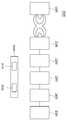
도 6 및 도 7은 본 발명의 실시예에 따른 송신측 코일부의 구조를 나타낸 도면.
도 8은 본 발명의 실시예에 따른 송신측 코일부를 나타낸 블록도.
도 9는 송신측 코일부의 등가 회로도.
도 10은 본 발명의 실시예에 따른 송신부에서 제1 및 제2 송신측 직류/교류 변환부와 제1 및 제2 송신측 임피던스 매칭부 그리고 제1 및 제2 송신측 코일부를 나타낸 도면.
도 11은 본 발명의 실시예에 따른 송신부가 제1 주파수 하에서 자기 공진 방식으로 전력을 공급 시 등가회로를 나타낸 도면.
도 12는 본 발명의 실시예에 따른 송신부가 제2 주파수 하에서 자기 유도 방식으로 전력을 공급 시 등가회로를 나타낸 도면.1 is a magnetic induction type equivalent circuit.
2 is a self-resonant-type equivalent circuit.
3 is a block diagram illustrating a transmitter as one of the subsystems constituting a wireless power transmission system;
4 is a block diagram illustrating a receiving unit as one of subsystems constituting a wireless power transmission system;
5 is a block diagram illustrating a wireless power transmission unit according to an embodiment of the present invention.
6 and 7 are views showing the structure of a transmission side coil unit according to an embodiment of the present invention.
8 is a block diagram showing a transmission side coil unit according to an embodiment of the present invention;
9 is an equivalent circuit diagram of a transmitting side coil part.
10 is a diagram illustrating first and second transmission side DC / AC conversion units, first and second transmission side impedance matching units, and first and second transmission side coil units according to an embodiment of the present invention.
11 is a diagram showing an equivalent circuit when power is supplied by a transmitting unit according to an embodiment of the present invention in a self-resonant manner under a first frequency.
12 is a diagram illustrating an equivalent circuit when a transmitter according to an embodiment of the present invention supplies power in a magnetic induction manner at a second frequency.
이하, 본 발명의 실시예에 의한 무선전력 송신부의 도면을 참고하여 상세하게 설명한다. 다음에 소개되는 실시 예들은 당업자에게 본 발명의 사상이 충분히 전달될 수 있도록 하기 위해 예로서 제공되는 것이다. 따라서, 본 발명은 이하 설명되는 실시 예들에 한정되지 않고 다른 형태로 구체화될 수도 있다. 그리고, 도면들에 있어서, 장치의 크기 및 두께 등은 편의를 위하여 과장되어 표현될 수도 있다. 명세서 전체에 걸쳐서 동일한 참조 번호들은 동일한 구성요소들을 나타낸다.Hereinafter, a detailed description will be given with reference to the drawings of a wireless power transmission unit according to an embodiment of the present invention. The following embodiments are provided by way of example so that those skilled in the art can fully understand the spirit of the present invention. Therefore, the present invention is not limited to the embodiments described below, but may be embodied in other forms. In the drawings, the size and thickness of an apparatus may be exaggerated for convenience. Like reference numerals designate like elements throughout the specification.
본 발명의 이점 및 특징, 그리고 그것들을 달성하는 방법은 첨부되는 도면과 함께 상세하게 후술되어 있는 실시예들을 참조하면 명확해질 것이다. 그러나, 본 발명은 이하에서 개시되는 실시예들에 한정되는 것이 아니라 서로 다른 다양한 형태로 구현될 것이며, 단지 본 실시예들은 본 발명의 개시가 완전하도록 하며, 본 발명이 속하는 기술분야에서 통상의 지식을 가진 자에게 발명의 범주를 완전하게 알려주기 위해 제공되는 것이며, 본 발명은 청구항의 범주에 의해 정의될 뿐이다. 명세서 전체에 걸쳐 동일 참조 부호는 동일 구성요소를 지칭한다. 도면에서 층 및 영역들의 크기 및 상대적인 크기는 설명의 명료성을 위해 과장될 수 있다.BRIEF DESCRIPTION OF THE DRAWINGS The advantages and features of the present invention, and the manner of achieving them, will be apparent from and elucidated with reference to the embodiments described hereinafter in conjunction with the accompanying drawings. It should be understood, however, that the invention is not limited to the disclosed embodiments, but is capable of many different forms and should not be construed as limited to the embodiments set forth herein. Rather, these embodiments are provided so that this disclosure will be thorough and complete, To fully disclose the scope of the invention to those skilled in the art, and the invention is only defined by the scope of the claims. Like reference numerals refer to like elements throughout the specification. The dimensions and relative sizes of the layers and regions in the figures may be exaggerated for clarity of illustration.
본 명세서에서 사용된 용어는 실시예들을 설명하기 위한 것이며, 따라서 본 발명을 제한하고자 하는 것은 아니다. 본 명세서에서, 단수형은 문구에서 특별히 언급하지 않는 한 복수형도 포함한다. 명세서에서 사용되는 "포함한다 (comprise)" 및/또는 "포함하는(comprising)"은 언급된 구성요소, 단계, 동작 및/ 또는 소자는 하나 이상의 다른 구성요소, 단계, 동작 및/또는 소자의 존재 또는 추가를 배제하지 않는다.The terminology used herein is for the purpose of describing embodiments only and is not intended to be limiting of the invention. In the present specification, the singular form includes plural forms unless otherwise specified in the specification. &Quot; comprise "and / or" comprising ", as used in the specification, means that the presence of stated elements, Or additions.
실시예는 무선 전력 전송을 위하여 저주파(50kHz)부터 고주파(15MHz)까지의 다양한 종류의 주파수 대역을 선택적으로 사용하며, 시스템 제어를 위하여 데이터 및 제어신호를 교환할 수 있는 통신시스템의 지원이 필요하다.Embodiments use a variety of frequency bands from low frequency (50 kHz) to high frequency (15 MHz) selectively for wireless power transmission, and it is necessary to support a communication system capable of exchanging data and control signals for system control .
실시예는 배터리를 사용하거나 필요로 하는 전자기기를 사용하는 휴대단말 산업, 스마트 시계 산업, 컴퓨터 및 노트북 산업, 가전기기 산업, 전기자동차 산업, 의료기기 산업, 로봇 산업 등 다양한 산업분야에 적용될 수 있다.The embodiments can be applied to various industrial fields such as a mobile terminal industry using a battery or an electronic device required, a smart clock industry, a computer and notebook industry, a household appliance industry, an electric car industry, a medical device industry, and a robot industry .
실시예는 기기를 제공한 하나 또는 복수개의 전송 코일을 사용하여 한 개 이상의 다수기기에 전력 전송이 가능한 시스템을 고려할 수 있다.Embodiments may consider a system capable of power transmission to one or more multiple devices using one or more transmit coils that provide the device.
실시예에 따르면 스마트폰, 노트북 등 모바일 기기에서의 배터리 부족문제를 해결할 수 있고, 일 예로 테이블에 무선충전패드를 놓고 그 위에서 스마트폰, 노트북을 사용하면 자동으로 배터리가 충전되어 장시간 사용할 수 있게 된다. 또한 까페, 공항, 택시, 사무실, 식당 등 공공장소에 무선충전패드를 설치하면 모바일기기 제조사별로 상이한 충전단자에 상관없이 다양한 모바일기기를 충전이 가능하다. 또한 무선전력전송 기술이 청소기, 선풍기 등의 생활가전제품에 적용되면 전원케이블을 찾아 다닐 필요가 없게 되고 가정 내에서 복잡한 전선이 사라지면서 건물 내 배선이 줄고 공간활용 폭도 넓어질 수 있다. 또한 현재의 가정용 전원으로 전기자동차를 충전할 경우 많은 시간이 소요되지만 무선전력전송 기술을 통해서 고전력을 전송한다면 충전시간을 줄일 수 있게 되고 주차장 바닥에 무선충전시설을 설치하게 되면 전기자동차 주변에 전원케이블을 준비 해야 하는 불편함을 해소 할 수 있다.According to the embodiment, it is possible to solve the battery shortage problem in a mobile device such as a smart phone and a notebook. For example, when a wireless charging pad is placed on a table and a smart phone or a notebook is used on the table, the battery is automatically charged and can be used for a long time . In addition, by installing wireless charging pads in public places such as cafes, airports, taxis, offices, restaurants, etc., mobile devices manufacturers can charge various mobile devices regardless of charging terminals. In addition, when wireless power transmission technology is applied to household electrical appliances such as cleaners, electric fans, etc., there is no need to look for power cables and complex wires can be eliminated in the home, which can reduce wiring in buildings and increase the space utilization. In addition, it takes a lot of time to charge the electric car with the current household power, but if the high power is transmitted through the wireless power transmission technology, the charging time can be reduced. If the wireless charging facility is installed at the bottom of the parking lot, It is possible to solve the inconvenience of having to prepare.
실시예에서 사용되는 용어와 약어는 다음과 같다.The terms and abbreviations used in the examples are as follows.
무선전력전송 시스템 (Wireless Power Transfer System):자기장 영역 내에서 무선 전력 전송을 제공하는 시스템Wireless Power Transfer System: A system that provides wireless power transmission within a magnetic field region
송신부(Wireless Power Transfer System-Charger): 자기장 영역 내에서 다수기기의 전력수신기에게 무선전력전송을 제공하며 시스템 전체를 관리하는 장치.Wireless Power Transfer System-Charger: A device that provides wireless power transmission to power receivers of multiple devices within a magnetic field area and manages the entire system.
수신부(Wireless Power Transfer System-Deivce): 자기장 영역 내에서 전력송신기로부터 무선전력 전송을 제공받는 장치.Wireless Power Transfer System-Deivce: A device that is provided with a wireless power transmission from a power transmitter within a magnetic field area.
충전 영역(Charging Area): 자기장 영역 내에서 실제적인 무선 전력 전송이 이루어지는 지역이며, 응용 제품의 크기, 요구 전력, 동작주파수에 따라 변할 수 있다.Charging Area: A region where actual wireless power transmission occurs within the magnetic field region, and may vary depending on the size, required power, and operating frequency of the application product.
S 파라미터(Scattering parameter): S 파라미터는 주파수 분포상에서 입력전압 대 출력전압의 비로 입력 포트 대 출력 포트의 비(Transmission; S21) 또는 각각의 입/출력 포트의 자체 반사값, 즉 자신의 입력에 의해 반사되어 돌아오는 출력의 값(Reflection; S11, S22).Scattering parameter: The S parameter is the ratio of the input port to the output port in terms of the input voltage to the output voltage on the frequency distribution (Transmission S21) or the self reflection value of each input / output port, Reflection (S11, S22) of the reflected output.
품질 지수 Q(Quality factor): 공진에서 Q의 값은 주파수 선택의 품질을 의미하고 Q 값이 높을수록 공진 특성이 좋으며, Q 값은 공진기에서 저장되는 에너지와 손실되는 에너지의 비로 표현됨.Quality factor Q: The value of Q in resonance means the quality of frequency selection. The higher the Q value, the better the resonance characteristics. The Q value is expressed as the ratio of the energy stored in the resonator to the energy lost.
무선으로 전력을 전송하는 원리를 살펴보면, 무선 전력 전송 원리로 크게 자기 유도 방식과 자기 공진 방식이 있다.The principles of wireless power transmission include magnetic induction and self-resonance.
자기 유도 방식은 소스 인덕터(Ls)와 부하 인덕터(Ll)를 서로 근접시켜 한쪽의 소스 인덕터(Ls)에 전류를 흘리면 발생한 자속을 매개로 부하 인덕터(Ll)에도 기전력이 발생하는 비접촉 에너지 전송기술이다. 그리고 자기 공진 방식은 2개의 공진기를 결합하는 것으로 2개의 공진기 간의 고유의 주파수에 의한 자기 공진이 발생하여 동일 주파수로 진동 하면서 동일 파장 범위에서 전기장 및 자기장을 형성시키는 공명 기법을 활용하여 에너지를 무선으로 전송하는 기술이다.The magnetic induction method is a noncontact energy transfer technique in which an electromotive force is generated in the load inductor Ll via a magnetic flux generated when the source inductor Ls and the load inductor L1 are brought close to each other and a current is supplied to one of the source inductors Ls . The self-resonance method combines two resonators to generate self-resonance due to the inherent frequency between two resonators, resonating at the same frequency and utilizing resonance techniques to form an electric field and a magnetic field in the same wavelength range. Transmission technology.
도 1은 자기 유도 방식 등가회로이다.1 is a magnetic induction equivalent circuit.
도 1을 참조하면, 자기 유도 방식 등가회로에서 송신부는 전원을 공급하는 장치에 따른 소스 전압(Vs), 소스 저항(Rs), 임피던스 매칭을 위한 소스 커패시터(Cs) 그리고 수신부와의 자기적 결합을 위한 소스 코일(Ls)로 구현될 수 있고, 수신부는 수신부의 등가 저항인 부하 저항(Rl), 임피던스 매칭을 위한 부하 커패시터(Cl) 그리고 송신부와의 자기적 결합을 위한 부하 코일(Ll)로 구현될 수 있고, 소스 코일(Ls)과 부하 코일(Ll)의 자기적 결합 정도는 상호 인덕턴스(Msl)로 나타낼 수 있다.Referring to FIG. 1, in a magnetic induction equivalent circuit, a transmitter includes a source voltage Vs, a source resistance Rs, a source capacitor Cs for impedance matching, and a magnetic coupling with a receiving unit, And a load coil Rl for an impedance matching and a load coil Ll for magnetic coupling with a transmitting unit. The load coil Rl may be implemented as a source coil Ls for impedance matching, And the degree of magnetic coupling between the source coil Ls and the load coil Ll can be expressed by mutual inductance Msl.
도 1에서 임피던스 매칭을 위한 소스 커패시터(Cs)와 부하 커패시터(Cl)이 없는 오로지 코일로만 이루어진 자기 유도 등가회로로부터 입력전압 대 출력전압의 비(S21)를 구하여 이로부터 최대 전력 전송 조건을 찾으면 최대 전력 전송 조건은 이하 수학식 1을 충족한다.In FIG. 1, the ratio S21 of the input voltage to the output voltage is obtained from the magnetic induction equivalent circuit consisting only of the coil without the source capacitor Cs and the load capacitor Cl for impedance matching, The power transmission condition satisfies Equation (1) below.
수학식 1
Ls/Rs=Ll/RlLs / Rs = L1 / R1
상기 수학식 1에 따라 송신 코일(Ls)의 인덕턴스와 소스 저항(Rs)의 비와 부하 코일(Ll)의 인덕턴스와 부하 저항(Rl)의 비가 같을 때 최대 전력 전송이 가능하다. 인덕턴스만 존재하는 시스템에서는 리액턴스를 보상할 수 있는 커패시터가 존재하지 않기 때문에 최대 전력 전달이 이루이지는 지점에서 입/출력 포트의 자체 반사값(S11)의 값은 0이 될 수 없고, 상호 인덕턴스(Msl) 값에 따라 전력 전달 효율이 크게 변화할 수 있다. 그리하여 임피던스 매칭을 위한 보상 커패시터로써 송신부에 소스 커패시터(Cs)가 부가될 수 있고, 수신부에 부하 커패시터(Cl)가 부가될 수 있다. 상기 보상 커패시터(Cs, Cl)는 예로 수신 코일(Ls) 및 부하 코일(Ll) 각각에 직렬 또는 병렬로 연결될 수 있다. 또한 임피던스 매칭을 위하여 송신부 및 수신부 각각에는 보상 커패시터 뿐만 아니라 추가적인 커패시터 및 인덕터와 같은 수동 소자가 더 부가될 수 있다.The maximum power transmission is possible when the ratio of the inductance of the transmission coil Ls to the source resistance Rs and the ratio of the inductance of the load coil Ll to the load resistance Rl are equal to each other. Since there is no capacitor that can compensate for reactance in a system with only an inductance, the value of the self reflection value S11 of the input / output port can not be zero at the point where the maximum power transfer occurs, and the mutual inductance Msl), the power transmission efficiency may vary greatly. Thus, the source capacitor Cs may be added to the transmitter as a compensation capacitor for impedance matching, and the load capacitor Cl may be added to the receiver. The compensation capacitors Cs and Cl may be connected in series or in parallel to the receiving coil Ls and the load coil Ll, respectively. For impedance matching, a passive element such as an additional capacitor and an inductor may be added to each of the transmitter and the receiver as well as the compensation capacitor.
도 2는 자기 공진 방식 등가회로이다.2 is a self-resonant-type equivalent circuit.
도 2를 참조하면, 자기 공진 방식 등가회로에서 송신부는 소스 전압(Vs), 소스 저항(Rs) 그리고 소스 인덕터(Ls)의 직렬 연결로 폐회로를 구성하는 소스 코일(Source coil)과 송신측 공진 인덕터(L1)와 송신측 공진 커패시터(C1)의 직렬 연결로 폐회로를 구성하는 송신측 공진 코일(Resonant coil)로 구현되고, 수신부는 부하 저항(Rl)와 부하 인덕터(Ll)의 직렬 연결로 폐회로를 구성하는 부하 코일(Load coil)과 수신측 공진 인덕터(L2)와 수신측 공진 커패시터(C2)의 질렬 연결로 폐회로를 구성하는 수신측 공진 코일로 구현되며, 소스 인덕터(Ls)와 송신측 인덕터(L1)는 K01의 결합계수로 자기적으로 결합되고, 부하 인덕터(Ll)와 부하측 공진 인덕터(L2)는 K23의 결합계수로 자기적으로 결합되고, 송신측 공진 인덕터(L1)와 수신측 공진 인덕터(L2)는 L12의 결합 계수로 자기적으로 결합된다.2, in the self-resonant type equivalent circuit, a transmitter includes a source coil constituting a closed circuit by a series connection of a source voltage Vs, a source resistor Rs and a source inductor Ls, Side resonant coil constituting a closed circuit by a series connection of the transmission line L1 and the transmission-side resonance capacitor C1, and the reception unit is realized by a series connection of the load resistance Rl and the load inductor Ll, Side resonance coil constituting a closed circuit by a series connection of a load coil constituting a receiving side resonance inductor L2 and a receiving side resonance capacitor C2 and a receiving side resonance coil constituting a closed circuit constituted by a source inductor Ls and a transmitting side inductor L1 are magnetically coupled to each other by a coupling coefficient of K01 and the load inductor L1 and the load side resonance inductor L2 are magnetically coupled to each other by a coupling coefficient of K23 and the transmission side resonance inductor L1 and the reception side resonance inductor L2, (L2) is the coupling coefficient of L12, .
자기 공진 방식은 두 공진기의 공진 주파수가 동일할 때에는 송신부의 공진기의 에너지의 대부분이 수신부의 공진기로 전달되어 전력 전달 효율이 향상될 수 있고, 자기 공진 방식에서의 효율은 이하 수학식 2를 충족할 때 좋아진다.When the two resonators have the same resonance frequency, most of the energy of the resonator of the transmitter is transmitted to the resonator of the receiver so that the power transfer efficiency can be improved, and the efficiency in the self resonance method satisfies Equation When it gets better.
수학식 2
k/Γ >> 1 (k는 결합계수, Γ 감쇄율)k / Γ >> 1 (k is the coupling coefficient, Γ attenuation factor)
자기 공진 방식에서 효율을 증가시키기 위하여 임피던스 매칭을 위한 소자를 부가할 수 있고, 임피던스 매칭 소자는 인덕터 및 커패시터와 같은 수동 소자가 될 수 있다.In order to increase the efficiency in the self-resonant mode, an element for impedance matching can be added, and the impedance matching element can be a passive element such as an inductor and a capacitor.
이와 같은 무선 전력 전송 원리를 바탕으로 자기 유도 방식 또는 자기 공진 방식으로 전력을 전달하기 위한 무선전력전송 시스템을 살펴본다.Based on such a wireless power transmission principle, a wireless power transmission system for transmitting power by a magnetic induction method or a self resonance method will be described.
도 3은 무선전력전송 시스템을 구성하는 서브 시스템 중 하나로 송신부를 나타낸 블록도이다.3 is a block diagram showing a transmitter as one of subsystems constituting a wireless power transmission system.
도 3을 참조하면, 무선전력전송 시스템은 송신부(1000)와 상기 송신부(1000)로부터 무선으로 전력을 전송받는 수신부(2000)를 포함할 수 있고, 상기 송신부(1000)는 송신측 교류/직류 변환부(1100), 송신측 직류/교류 변환부(1200), 송신측 임피던스 매칭부(1300), 송신 코일부(1400) 그리고 송신측 통신 및 제어부(1500)을 포함할 수 있다.3, the wireless power transmission system may include a
송신측 교류/직류 변환부(1100)는 송신측 통신 및 제어부(1500)의 제어 하에 외부로부터 제공되는 교류 신호를 직류 신호로 변환하는 전력 변환부로써, 상기 송신측 교류/직류 변환부(1100)는 서브 시스템으로 정류기(1110)와 송신측 직류/직류 변환부(1120)을 포함할 수 있다. 상기 정류기(1110)는 제공되는 교류 신호를 직류 신호로 변환하는 시스템으로써 이를 구현하는 실시예로 고주파수 동작 시 상대적으로 높은 효율을 가지는 다이오드 정류기, 원-칩(one-chip)화가 가능한 동기 정류기 또는 원가 및 공간 절약이 가능하고 및 데드 타임(Dead time)의 자유도가 높은 하이브리드 정류기가 될 수 있다. 또한 상기 송신측 직류/직류 변환부(1120)는 송신측 통신 및 제어부(1500)의 제어 하에 상기 정류기(1110)으로부터 제공되는 직류 신호의 레벨을 조절하는 것으로 이를 구현하는 예로 입력 신호의 레벨을 낮추는 벅 컨버터(Buck converter), 입력 신호의 레벨을 높이는 부스트 컨버터(Boost converter), 입력 신호의 레벨을 낮추거나 높일 수 있는 벅 부스트 컨버터(Buck Boost converter) 또는 축 컨버터(Cuk converter)가 될 수 있다. 또한 상기 송신측 직류/직류 변환부(1120)는 전력 변환 제어 기능을 하는 스위치소자와 전력 변환 매개 역할 또는 출력 전압 평활 기능을 하는 인덕터 및 커패시터, 전압 이득을 조절 또는 전기적인 분리 기능(절연 기능)을 하는 트랜스 등을 포함할 수 있으며, 입력되는 직류 신호에 포함된 리플 성분 또는 맥동 성분(직류 신호에 포함된 교류 성분)을 제거하는 기능을 할 수 있다. 그리고 상기 송신측 직류/직류 변환부(1120)의 출력 신호의 지령치와 실제 출력 치와의 오차는 피드백 방식을 통해 조절될 수 있고, 이는 상기 송신측 통신 및 제어부(1500)에 의하여 이루어 질 수 있다.The transmitting side AC /
송신측 직류/교류 변환부(1200)는 송신측 통신 및 제어부(1500)의 제어 하에 송신측 교류/직류 변환부(1100)으로부터 출력되는 직류 신호를 교류 신호로 변환하고, 변환된 교류 신호의 주파수를 조절할 수 있는 시스템으로 이를 구현하는 예로 하프 브릿지 인버터(Half bridge inverter) 또는 풀 브릿지 인버터(Full bridge inverter)가 있다. 또한 상기 송신측 직류/교류 변환부(1200)는 출력 신호의 주파수를 생성하는 오실레이터(Ocillator)와 출력 신호를 증폭하는 파워 증폭부를 포함할 수 있다.The transmission side DC /
송신측 임피던스 매칭부(1300)는 서로 다른 임피던스를 가진 지점에서 반사파를 최소화하여 신호의 흐름을 좋게 한다. 송신부(1000)와 수신부(2000)의 두 코일은 공간적으로 분리되어 있어 자기장의 누설이 많으므로 상기 송신부(1000)와 수신부(2000)의 두 연결단 사이의 임피던스 차이를 보정하여 전력 전달 효율을 향상시킬 수 있다. 상기 송신측 임피던스 매칭부(1300)는 인덕터, 커패시터 그리고 저항 소자로 구성될 수 있고, 통신 및 제어부(1500)의 제어 하에 상기 인덕터의 인덕턴스와 커패시터의 커패시턴스 그리고 저항의 저항 값을 가변하여 임피던스 매칭을 위한 임피던스 값을 조정할 수 있다. 그리고 무선전력전송 시스템이 자기 유도 방식으로 전력을 전송하는 경우, 송신측 임피던스 매칭부(1300)는 직렬 공진 구조 또는 병렬 공진 구조를 가질 수 있고, 송신부(1000)와 수신부(2000) 사이의 유도 결합 계수를 증가시켜 에너지 손실을 최소화 할 수 있다. 그리고 무선전력전송 시스템이 자기 공진 방식으로 전력을 전송하는 경우, 송신측 임피던스 매칭부(1300)는 송신부(1000)와 수신부(2000) 간의 이격 거리가 변화되거나 금속성 이물질, 다수의 디바이스에 의한 상호 영향 등에 따라 코일의 특성의 변화로 에너지 전송 선로상의 매칭 임피던스 변화에 따른 임피던스 매칭의 실시간 보정을 가능하게 할 수 있고, 그 보정 방식으로써 커패시터를 이용한 멀티 매칭 방식, 멀티 안테나를 이용한 매칭 방식, 멀티 루프를 이용한 방식 등이 될 수 있다.The transmission-side
송신측 코일(1400)은 복수개의 코일 또는 단수개의 코일로 구현될 수 있고, 송신측 코일(1400)이 복수개로 구비되는 경우 이들은 서로 이격되어 배치되거나 서로 중첩되어 배치될 수 있고, 이들이 중첩되어 배치되는 경우 중첩되는 면적은 자속 밀도의 편차를 고려하여 결정할 수 있다. 또한 송신측 코일(1400)을 제작할 때 내부 저항 및 방사 저항을 고려하여 제작할 수 있고, 이 때 저항 성분이 작으면 품질 지수(Quality factor)가 높아지고 전송 효율이 상승할 수 있다.The transmitting
통신 및 제어부(1500)는 서브 시스템으로써 송신측 제어부(1510)와 송신측 통신부(1520)를 포함할 수 있다. 상기 송신측 제어부(1510)는 수신부(2000)의 전력 요구량, 현재 충전량 그리고 무선 전력 방식을 고려하여 상기 송신측 교류/직류 변환부(1100)의 출력 전압을 조절하는 역할을 할 수 있다. 그리고 최대 전력 전송 효율를 고려하여 상기 송신측 직류/교류 변환부(1200)를 구동하기 위한 주파수 및 스위칭 파형들을 생성하여 전송될 전력을 제어할 수 있다. 또한 수신부(2000)의 저장부(미도시)로부터 독출한 제어에 요구되는 알고리즘, 프로그램 또는 어플리케이션을 이용하여 수신부(2000)의 동작 전반을 제어할 수 있다. 한편 상기 송신측 제어부(1510)는 마이크로프로세서, 마이크로컨트롤유닛(Micro Controller Unit) 또는 마이콤(Micom)이라고 지칭할 수 있다. 상기 송신측 통신부(1520)는 수신측 통신부(2620)와 통신을 수행할 수 있고, 통신 방식의 일 예로 블루투스 방식을 이용할 수 있다. 상기 송신측 통신부(1520)와 수신측 통신부(2620)는 서로간에 충전 상황 정보 및 충전 제어 명령 등의 송수신을 진행할 수 있다. 그리고 상기 충전 상황 정보로는 수신부(2000)의 개수, 배터리 잔량, 충전 횟수, 사용량, 배터리 용량, 배터리 비율 그리고 송신부(1000)의 전송 전력량 등을 포함할 수 있다. 또한 송신측 통신부(1520)는 수신부(2000)의 충전 기능을 제어하는 충전 기능 제어 신호를 송신할 수 있고, 상기 충전 기능 제어 신호는 수신부(2000)를 제어하여 충전 기능을 인에이블(enabled) 또는 디스에이블(disabled)하게 하는 제어 신호일 수 있다.The communication and
한편 송신부(1000)는 송신측 통신부(1520)와 상이한 하드웨어로 구성되어 송신부(1000)가 아웃-밴드(out-band) 형식으로 통신될 수 도 있다. 그리고, 송신부(1000)와 송신측 통신부(1520)가 하나의 하드웨어로 구현되어, 송신부(1000)가 인-밴드(in-band) 형식으로 통신을 수행할 수도 있다. 또한 상기 송신측 통신부(1520)는 상기 송신측 제어부(1510)와 별로로 구성될 수 있고, 상기 수신부(2000) 또한 수신측 통신부(2620)가 수신 장치의 제어부(2610)에 포함되거나 별도로 구성될 수 있다.Meanwhile, the
도 4는 무선전력전송 시스템을 구성하는 서브 시스템 중 하나로 수신부를 나타낸 블록도이다.4 is a block diagram illustrating a receiving unit as one of the subsystems constituting the wireless power transmission system.
도 4를 참조하면, 무선전력전송 시스템은 송신부(1000)와 상기 송신부(1000)로부터 무선으로 전력을 전송받는 수신부(2000)를 포함할 수 있고, 상기 수신부(2000)는 수신측 코일부(2100), 수신측 임피던스 매칭부(2200), 수신측 교류/직류 변환부(2300), 직류/직류변환부(2400), 부하(2500) 및 수신측 통신 및 제어부(2600)를 포함할 수 있다.4, the wireless power transmission system may include a
수신측 코일부(2100)은 자기 유도 방식 또는 자기 공진 방식을 통해 전력을 수신할 수 있다. 이와 같이 전력 수신 방식에 따라서 유도 코일 또는 공진 코일 중 적어도 하나 이상을 포함할 수 있다. 그리고 수신측 코일부(2100)는 근거리 통신용 안테나(Near Field Communication)를 함께 구비할 수 있다. 그리고 상기 수신측 코일부(2100)은 송신측 코일부(1400)와 동일할 수 있고, 수신 안테나의 치수는 수신부(200)의 전기적 특성에 따라 달라질 수 있다.The receiving
수신측 임피던스 매칭부(2200)는 송신기(1000)와 수신기(2000) 사이의 임피던스 매칭을 수행한다.The receiving-side
상기 수신측 교류/직류 변환부(2300)는 수신측 코일부(2100)으로부터 출력되는 교류 신호를 정류하여 직류 신호를 생성한다.The receiving-side AC /
수신측 직류/직류변환부(2400)는 수신측 교류/직류 변환부(2300)에서 출력되는 직류 신호의 레벨을 부하(2500)의 용량에 맞게 조정할 수 있다.The receiving-side DC /
상기 부하(2500)는 배터리, 디스플레이, 음성 출력 회로, 메인 프로세서 그리고 각종 센서들을 포함할 수 있다.The
수신측 통신 및 제어부(2600)는 송신측 통신 및 제어부(1500)로부터 웨이크-업 전력에 의해 활성화 될 수 있고, 상기 송신측 통신 및 제어부(1500)와 통신을 수행하고, 수신부(2000)의 서브 시스템의 동작을 제어할 수 있다.The receiving side communication and
상기 수신부(2000)는 단수 또는 복수개로 구성되어 송신부(1000)로부터 동시에 에너지를 무선으로 전달 받을 수 있다. 즉 자기 공진 방식의 무선전력전송 시스템에서는 하나의 송신부(1000)로부터 복수의 타켓 수신부(2000)가 전력을 공급받을 수 있다. 이때 상기 송신부(1000)의 송신측 매칭부(1300)는 복수개의 수신부(2000)들 사이의 임피던스 매칭을 적응적으로 수행할 수 있다. 이는 자기 유도 방식에서 서로 독립적인 수신측 코일부를 복수개 구비하는 경우에도 동일하게 적용될 수 있다.The receiving
또한 상기 수신부(2000)가 복수개로 구성된 경우 전력 수신 방식이 동일한 시스템이거나, 서로 다른 종류의 시스템이 될 수 있다. 이 경우, 송신부(1000)는 자기 유도 방식 또는 자기 공진 방식으로 전력을 전송하는 시스템이거나 양 방식을 혼용한 시스템일 수 있다.When the
한편 무선전력전송 시스템의 신호의 크기와 주파수 관계를 살펴보면, 자기 유도 방식의 무선 전력 전송의 경우, 송신부(1000)에서 송신측 교류/직류 변환부(1100)은 110V~220V의 60Hz의 교류 신호를 인가 받아 10V 내지 20V의 직류 신호로 변환하여 출력할 수 있고, 송신측 직류/교류 변환부(1200)는 직류 신호를 인가받아 125KHz의 교류 신호를 출력할 수 있다. 그리고 수신부(2000)의 수신측 교류/직류 변환부(2300)는 125KHz의 교류 신호를 입력 받아 10V 내지 20V의 직류 신호로 변환하여 출력할 수 있고, 수신측 직류/직류변환부(2400)는 부하(2500)에 적합한, 예를 들어 5V의 직류 신호를 출력하여 상기 부하(2500)에 전달할 수 있다. 그리고 자기 공진 방식의 무선 전력 전송의 경우, 송신부(1000)에서 송신측 교류/직류 변환부(1100)은 110V~220V의 60Hz의 교류 신호를 인가 받아 10V 내지 20V의 직류 신호로 변환하여 출력할 수 있고, 송신측 직류/교류 변환부(1200)는 직류 신호를 인가받아 6.78MHz의 교류 신호를 출력할 수 있다. 그리고 수신부(2000)의 수신측 교류/직류 변환부(2300)는 6.78MHz의 교류 신호를 입력 받아 10V 내지 20V의 수신측 직류 신호로 변환하여 출력할 수 있고, 직류/직류변환부(2400)는 부하(2500)에 적합한, 예를 들어 5V의 직류 신호를 출력하여 상기 부하(2500)에 전달할 수 있다.Meanwhile, in the case of the radio power transmission of the magnetic induction type, the transmission side AC /
도 5는 본 발명의 실시예에 따른 무선전력전송 송신부를 나타낸 블록도이다.5 is a block diagram illustrating a wireless power transmission unit according to an embodiment of the present invention.
도 5를 참조하면, 본 발명의 실시예에 따른 송신부(1000)의 송신측 직류/교류 변환부(1200)는 제1 및 제2 직류/교류 변환부(1210, 1220)을 포함할 수 있고, 송신측 임피던스 매칭부(1300)는 제1 및 제2 임피던스 매칭부(1310, 1320)를 포함할 수 있다. 그리고 송신측 코일부(1400)는 제1 및 제2 송신측 코일부(1410, 1420)를 포함할 수 있다.5, the transmitting side DC /
상기 송신부(1000)는 제1 송신측 코일부(1410)와 제2 송신측 코일부(1420) 그리고 상기 제2 송신측 코일부(1420)의 양단에 연결된 스위치부(1430)를 포함할 수 있다. 상기 스위치부(1430)는 적어도 하나의 스위치 소자를 포함하고, 상기 스위치부(1430)는 상기 제1 송신측 코일부(1410)를 구동하여 무선 전력을 전송할 때 턴 온(Turn On)됨으로써 단락되어 상기 제2 송신측 코일부(1420) 양단에 도선이 병렬 연결된 것과 같은 효과를 가져오고, 상기 제2 송신측 코일부(1420)를 구동하여 무선 전력을 전송할 때 턴 오프(Turn Off)됨으로써 개방되어 상기 제2 송신측 코일부(1420)의 양단에 무한대의 저항이 병렬 연결된 것과 같은 효과를 가져올 수 있다.The
상기 제1 송신측 코일부(1410)는 공진형 코일부일 수 있고, 이 경우 상기 제1 직류/교류 변환부(1210)는 상기 공진형 코일부(1410)에 제1 주파수인 6.78MHz 또는 6.78MHz 근방의 주파수를 가진 교류 전력을 제공할 수 있으며, 상기 제1 임피던스 매칭부(1310)는 상기 공진형 코일부(1410)와 수신부(200)의 수신측 코일부(2100)간의 임피던스 매칭을 수행할 수 있다.The first DC /
또한 상기 제2 송신측 코일부(1420)는 유도형 코일부일 수 있고, 이 경우 상기 제2 직류/교류 변환부(1220)는 상기 유도형 코일부(1420)에 제2 주파수인 125KHz 또는 125KHz 근방의 주파수를 가진 교류 전력을 제공할 수 있으며, 상기 제2 임피던스 매칭부(1320)는 상기 유도형 코일부(1420)와 수신부(200)의 수신측 코일부(2100)간의 임피던스 매칭을 수행할 수 있다.The second DC /
한편 송신측 통신 및 제어부(1500)는 상기 제1 직류/교류 변환부(1210) 또는 제2 직류/교류 변환부(1220) 중 어느 하나를 제어하여 송신부(1000)가 자기 공진 방식 또는 자기 유도 방식으로 무선 전력을 전송하도록 할 수 있다. 즉, 상기 송신측 통신 및 제어부(1500)는 상기 제1 직류/교류 변환부(1210)가 구동하도록 상기 제1 직류/교류 변환부(1210)를 인에이블(enable)하고 상기 제2 직류/교류 변환부(1220)가 구동하지 않도록 상기 제2 직류/교류 변환부(1220)를 디스에이블(disable)하고, 상기 공진형 코일부(1410)에 제1 주파수의 신호를 공급함으로써 자기 공진 방식으로 송신부(1000)가 수신부(2000)로 전력 전송을 하고, 상기 송신측 통신 및 제어부(1500)는 상기 제2 직류/교류 변환부(1220)를 인에이블(enable)하고 상기 제1 직류/교류 변환부(1210)를 디스에이블(disable)하고, 상기 유도형 코일부(1420)에 제2 주파수의 신호를 공급함으로써 자기 유도 방식으로 송신부(1000)가 수신부(2000)로 전력을 전송하게 할 수 있다. 또한 상기 제1 직류/교류 변환부(1210)를 구동시키고, 상기 제2 직류/교류 변환부(1220)를 구동 시키지 않는 경우, 상기 제1 직류/교류 변환부(1210)의 동작에 동기하여 상기 송신측 통신 및 제어부(1500)로부터의 스위칭 제어 신호에 의해 스위치부(1430)의 스위치 소자를 단락시키고, 상기 제2 직류/교류 변환부(1220)를 구동시키고, 상기 제1 직류/교류 변환부(1210)를 구동 시키지 않는 경우, 상기 제2 직류/교류 변환부(1220)의 동작에 동기하여 상기 송신측 통신 및 제어부(1500)로부터의 스위칭 제어 신호에 의해 스위치부(1430)의 스위치 소자를 개방시킬 수 있다.On the other hand, the transmission side communication and
도 6 및 도 7은 본 발명의 실시예에 따른 송신측 코일부의 구조를 나타낸 도면이다.6 and 7 are views showing the structure of a transmission side coil unit according to an embodiment of the present invention.
도 6 및 도 7을 참조하면, 본 발명의 실시예에 따른 송신측 코일부(1400)는 코일이 실장되는 코일 인쇄회로기판(Printed circuit board; 3100)과 상기 코일 인쇄회로기판(3100)의 일면에 부착된 차폐제(3200) 그리고 상기 차폐제(3200)의 일면에 부착되고 상기 코일에 전기적 신호를 전송하는 송신 인쇄회로기판(3300)을 포함할 수 있다. 또한 상기 코일 인쇄회로기판(3100) 상에는 공진형 코일부(1410)를 구성하는 공진 코일(1411)과 유도형 코일부(1420)를 구성하는 유도 코일(1421)이 형성될 수 있다. 상기 공진 코일(1411)은 상기 코일 인쇄회로기판(3100)의 가장자리를 둘러싸며 배치될 수 있고, 상기 유도 코일(1421)은 상기 코일 인쇄회로기판(3100)의 중심 영역에 배치되어 상기 공진 코일(1411)이 상기 유도 코일(1421)을 감쌀 수 있다.6 and 7, the transmission
상기 차폐제(3200)는 상기 코일 인쇄회로기판(3100)과 상기 송신 인쇄회로기판(3300)을 전기적으로 격리하여, 상기 송신 인쇄회로기판(3300)의 구동에 따라 발생하는 전자기장의 상기 공진 및 유도 코일(1411, 1421)에 미치는 영향과 상기 공진 및 유도 코일(1411, 1421)의 구동에 따라 발생하는 전자기장의 상기 송신 인쇄회로기판(3300)에 미치는 영향을 최소화 할 수 있다.The shielding
도 8은 본 발명의 실시예에 따른 송신측 코일부를 나타낸 블록도이고, 도 9는 송신측 코일부의 등가 회로도이다.FIG. 8 is a block diagram showing a transmission side coil unit according to the embodiment of the present invention, and FIG. 9 is an equivalent circuit diagram of a transmission side coil unit.
도 8 및 도 9를 참조하면, 본 발명의 실시예에 따른 송신측 코일부(1400)는 공진형 코일부(1410)와 유도형 코일부(1420) 그리고 스위치부(1430)를 포함할 수 있다.8 and 9, a transmitting
상기 스위치부(1430)는 상기 유도형 코일부(1420)와 제2 임피던스 매칭부(1320) 사이에 연결되고, 구체적으로 상기 유도형 코일부(1420)와 병렬 연결되고, 상기 제2 임피던스 매칭부(1320)와 병렬로 연결될 수 있다.The
상기 스위치부(1430)는 상기 공진형 코일부(1410)에 제1 구동 주파수의 교류 신호가 공급될 때, 상기 유도형 코일부(1420)의 양단을 단락, 다시 말해 상기 유도형 코일부(1420)의 양단을 0V로 만드는 기능을 할 수 있다.When the AC signal of the first driving frequency is supplied to the resonance
각 구성을 등가회로로 표현하면, 상기 유도형 코일부(1420)는 제1 인덕터(L1)로 표현할 수 있고, 상기 제2 임피던스 매칭부(1320)는 상기 유도형 코일부(1420)의 일단에 일단이 연결되고 타단이 제1 노드(N1)에 연결된 제1 커패시터(C1), 상기 일단이 상기 제1 노드(N1)에 연결되고 타단이 제2 노드(N2)에 연결된 제2 커패시터(C2), 일단이 상기 제1 노드(N1)에 연결되고 타단이 제2 직류/교류 변환부(1220)의 일단에 연결된 제2 인덕터(L2) 그리고 일단이 상기 제2 노드(N2)에 연결되고 타단이 상기 제2 직류/교류 변환부(1220)의 타단에 연결된 제3 인덕터(L3)로 표현할 수 있으며, 상기 상기 공진형 코일부(1410)는 제4 인덕터(L4)로 표현할 수 있다.The
상기 스위치부(1430)는 송신측 통신 및 제어부(1500)로부터의 스위칭 제어 신호에 따라 구동할 수 있는 스위치 소자를 포함할 수 있다.The
상기 스위치 소자는 상기 제1 인덕터(L1) 양단에 연결, 즉 상기 제1 인덕터(L1)와 병렬 연결될 수 있다. 다시 말해 상기 제1 커패시터(C1)의 일단과 상기 제2 노드(N2) 사이에 연결될 수 있다.The switch element may be connected to both ends of the first inductor L1, that is, in parallel with the first inductor L1. That is, between one end of the first capacitor C1 and the second node N2.
이하 스위치부(1430)의 기능을 구체적으로 살펴본다.Hereinafter, the function of the
상기 스위치부(1430)가연결되지 않은 상태에서, 제1 주파수(f1)의 신호가 공진형 코일부(1410)에 인가될 때 상기 공진형 코일부(1410)에서 유도형 코일부(1420) 측을 바라본 입력 임피던스(Zin), 즉 상기 제4 인덕터(L4)에서 유도형 코일부(1420) 측을 바라본 입력 임피던스(Zin)을 구하면 하기 수학식 3을 충족할 수 있다.When the signal of the first frequency f1 is applied to the resonance
수학식 3

(상기 수학식에서

상기 수학식 3에서 입력 임피던스(Zin)의 리얼 파트(Real part)가 존재함으로 알 수 있고, 이러한 리얼 파트에 의하여 전력 손실이 발생할 수 있다.In Equation (3), it can be known that there exists a real part of the input impedance Zin, and power loss can be caused by the real part.
상기 스위치부(1430)가연결된 상태에서, 제1 주파수(f1)의 신호가 공진형 코일부(1410)에 인가되고, 상기 스위치부(1430)가 단락 상태가 되는 경우, 상기 공진형 코일부(1410)에서 유도형 코일부(1420) 측을 바라본 입력 임피던스(Zin), 즉 상기 제4 인덕터(L4)에서 유도형 코일부(1420) 측을 바라본 입력 임피던스(Zin)을 구하면 하기 수학식 4를 충족할 수 있다.While the
수학식 4

상기 수학식 4에서 입력 임피던스(Zin)는 리얼 파트(Real part)가 존재하지 않음을 알 수 있고, 이러한 리얼 파트에 부 존재로 인하여 제1 주파수(f1)로 공진형 코일부(1410)을 구동하는 경우 유도형 코일부(1420)에서의 전력 손실이 이상적으로는 0, 실제적으로는 전력 손실이 최소화됨을 알 수 있다.In Equation (4), it can be seen that the input impedance (Zin) does not include a real part, and the resonance
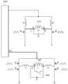
도 10은 본 발명의 실시예에 따른 송신부에서 제1 및 제2 송신측 직류/교류 변환부와 제1 및 제2 송신측 임피던스 매칭부 그리고 제1 및 제2 송신측 코일부를 나타낸 도면이다.10 is a diagram illustrating first and second transmission side DC / AC conversion units, first and second transmission side impedance matching units, and first and second transmission side coil units in a transmission unit according to an embodiment of the present invention.
도 10을 참조하면, 제1 송신측 직류/교류 변환부(1210)는 교류/직류 변환부(1100)로부터 제1 직류 신호(DC1)를 제5 노드(Ne) 노드로 입력 받아 제3 및 제4 노드(Nc, Nd) 양단으로 교류 신호를 출력할 수 있다. 그리고 상기 제3 및 제4 노드(Nc, Nd) 양단의 교류 신호에 의해 제1 송신측 코일부(1410)에 전류가 흐르고, 흐르는 전류에 의해 발생한 자속을 매개로 수신부(2000)의 수신측 코일부(2100)에 전력을 전송한다.10, the first transmitting side DC /
상기 제1 송신측 직류/교류 변환부(1210)는 제1 및 제2 스위치(Sa, Sb)와 제1 및 제2 고주파 필터부(1211, 1212)를 포함할 수 있다. 상기 제1 고주파 필터부(1211)는 제3 및 제5 노드(Nc, Ne) 사이에 접속되고, 상기 제2 고주파 필터부(1212)는 제4 및 제5 노드(Nd, Ne) 사이에 접속될 수 있다. 그리고 제1 스위치(Sa)는 제3 노드(Nc)와 기준 접지 사이에 접속될 수 있고, 제2 스위치(Sb)는 제4 노드(Nd)와 기준 접지 사이에 접속될 수 있다.The first transmission side DC /
상기 제1 및 제2 스위치(Sa, Sb)에는 상기 제1 및 제2 스위치(Sa, Sb)가 서로 교번하며 도통할 수 있도록 펄스 폭 변조 신호(Pulse width modulation signal)가 공급될 수 있고, 상기 상기 제1 및 제2 스위치(Sa, Sb)는 송신측 통신 및 제어부(1500)에 의하여 제1 주파수로 동작할 수 있다. 그리고 상기 제1 및 제2 고주파 필터부(1211, 1212)는 제5 노드(Ne)로부터 제공된 직류 신호(DC1)에 포함된 고주파 신호를 감쇠시킬 수 있고, 상기 제1 및 제2 고주파 필터부(1211, 1212) 각각은 적어도 하나 이상의 초크 코일(RFC)로 이루어질 수 있다.A pulse width modulation signal may be supplied to the first and second switches Sa and Sb so that the first and second switches Sa and Sb alternate with each other, The first and second switches Sa and Sb may operate at the first frequency by the transmission side communication and
상기 제1 송신측 임피던스 매칭부(1310)는 제3 내지 제5 커패시터(C3, C4, C5)를 포함할 수 있고, 상기 제3 커패시터(C3)는 제1 및 제3 노드(Na, Nc) 사이에 접속되고, 제4 커패시터(C4)는 제1 및 제2 노드(Na, Nb) 사이에 접속되고, 제5 커패시터(C5)는 제2 및 제4 노드(Na, Nd) 사이에 접속될 수 있다.The third capacitor C3 may include first and third nodes Na and Nc, and the third transmission line
상기 제1 송신측 코일부(1410)는 공진형 코일부로써 제1 및 제2 노드(Na, Nb) 사이에 접속될 수 있다.The first transmission
또한 스위치부(1430)는 상기 제1 송신측 코일부(1410) 양단, 즉 제1 및 제2 노드(Na, Nb) 사이에 접속될 수 있다.Further, the
상기 제2 송신측 직류/교류 변환부(1220)는 교류/직류 변환부(1100)로부터 제2 직류 신호(DC2)를 제5 노드(N5) 노드로 입력 받아 제3 및 제4 노드(N3, N4) 양단으로 교류 신호를 출력할 수 있다. 그리고 상기 제3 및 제4 노드(N3, N4) 양단의 교류 신호에 의해 제2 송신측 코일부(1420)에 전류가 흐르고, 흐르는 전류에 의해 발생한 자속을 매개로 수신부(2000)의 수신측 코일부(2100)에 전력을 전송한다.The second transmitting side DC /
상기 제2 송신측 직류/교류 변환부(1220)는 제1 내지 제4 스위치(S1, S2, S3, S4)를 포함할 수 있고, 상기 제1 스위치(S1)는 제3 노드(N3)와 제5 노드(N5) 사이에 접속될 수 있고, 상기 제2 스위치(S2)는 제3 노드(N3)와 기준 접지 사이에 접속될 수 있고, 상기 제3 스위치(S3)는 제4 노드(N4)와 제5 노드(N5) 사이에 접속될 수 있고, 상기 제4 스위치(S4)는 제4 노드(N4)와 기준 접지 사이에 접속될 수 있다.The second transmission side DC /
상기 제1 및 제4 스위치(S1, S4)는 동일 위상, 제2 및 제3 스위치(S2, S3)는 동일 위상 그리고 제1 및 제2 스위치(S1, S2)는 반대 위상을 가지고 스위칭 할 수 있다. 그리고 송신측 통신 및 제어부(1500)에 의하여 제2 주파수로 동작할 수 있다.The first and fourth switches S1 and S4 have the same phase and the second and third switches S2 and S3 have the same phase and the first and second switches S1 and S2 have the opposite phases. have. And can operate at the second frequency by the transmission side communication and
상기 제2 송신측 임피던스 매칭부(1320)는 제1 노드(N1)와 제3 노드(N3) 사이에 접속된 제2 인덕터(L2), 제2 노드(N2)와 제4 노드(N4) 사이에 접속된 제3 인덕터(L3), 제1 노드(N1)와 제6 노드(N6) 사이에 접속된 제1 커패시터(C1) 및 제1 노드(N1)와 제2 노드(N2) 사이에 접속된 제2 커패시터(C2)를 포함할 수 있다.The second transmitting
상기 제2 송신측 코일부(1420)는 유도형 코일부로써 제1 및 제2 노드(N1, N2) 사이에 접속될 수 있다.The second transmission
도 11은 본 발명의 실시예에 따른 송신부가 제1 주파수 하에서 자기 공진 방식으로 전력을 공급 시 등가회로를 나타낸 도면이다.11 is a diagram showing an equivalent circuit when power is supplied in a self-resonant manner under a first frequency by a transmitter according to an embodiment of the present invention.
도 11을 참조하면, 송신부(1000)가 자기 공진 방식으로 전력을 전송할 때, 제1 송신측 직류/교류 변환부(1210)에 제1 직류 신호(DC1)가 공급되고, 제2 송신측 직류/교류 변환부(1220)에 제2 직류 신호(DC2)의 공급이 차단될 수 있다. 그리고 스위치부(1430)는 단락될 수 있다. 따라서 상기 스위치부(1430)는 제6 및 제2 노드(N6, N2) 사이에 연결된 유도형 코일부(1420)에 도선이 병렬 연결된 효과를 가져와 상기 공진형 코일부(1410)에서 상기 유도형 코일부(1420)를 바라본 입력 임피던스(Zin)에서 저항 성분이 최소가 되도록 할 수 있고, 그에 따라 상기 공진현 코일부(1410)에서 발생한 자속이 유도형 코일부(1420)에 쇄교하면서 발생하는 전력 손실을 최소화할 수 있다.11, when the
도 12는 본 발명의 실시예에 따른 송신부가 제2 주파수 하에서 자기 유도 방식으로 전력을 공급 시 등가회로를 나타낸 도면이다.FIG. 12 is a diagram illustrating an equivalent circuit when the transmitter according to the embodiment of the present invention supplies power in a magnetic induction manner at a second frequency. FIG.
도 12를 참조하면, 송신부(1000)가 자기 유도 방식으로 전력을 전송할 때, 제1 송신측 직류/교류 변환부(1210)에 제1 직류 신호(DC1)의 공급이 차단되고, 제2 송신측 직류/교류 변환부(1220)에 제2 직류 신호(DC2)가 공급될 수 있다. 그리고 스위치부(1430)는 개방될 수 있다. 따라서 스위치부(1430)는 개방 회로처럼 동작하여 자기 유도 방식으로 전력을 전송할 때 송신부(1000)의 동작에 미치는 영향을 최소화할 수 있다.12, when the
이와 같이 본 발명에 따른 실시예는 자기 공진 방식과 자기 유도 방식에 따른 무선 전력 전송이 복합적으로 가능한 송신부(1000)의 경우, 하나의 코일 인쇄회로기판(3100)에 공진형 코일부(1410)와 유도형 코일부(1420)가 함께 실장되므로 상기 공진형 코일부(1410)와 유도형 코일부(1420)가 서로간의 상호 간섭을 일으켜 손실이 발생할 수 있으나, 일반적으로 유도형 코일부(1420)에서 발생한 자기장이 공진형 코일부(1410)에 결합되어 손실되는 양은 매우 작으나, 그 반대인 공진형 코일부(1410)에서 발생한 자기장이 유도형 코일부(1420)에 결합되어 발생하는 손실은 매우 클 수 있는 점을 고려하여 손실 억제부(1430)를 통해 공진형 코일부(1410)에서 유도형 코일부(1420)측을 바라본 입력 임피던스(Zin)에서 나타나는 반사 임피던스에서 실수 부분을 제거함으로써 전력 손실을 최소화할 수 있다.As described above, according to the embodiment of the present invention, in the case of the
이상에서 설명한 본 발명의 상세한 설명에서는 본 발명의 바람직한 실시 예를 참조하여 설명하였지만, 해당 기술 분야의 숙련된 당업자 또는 해당 기술분야에 통상의 지식을 갖는 자라면 후술할 특허청구범위에 기재된 본 발명의 사상 및 기술 영역으로부터 벗어나지 않는 범위 내에서 본 발명을 다양하게 수정 및 변경시킬 수 있음을 이해할 수 있을 것이다. 따라서, 본 발명의 기술적 범위는 명세서의 상세한 설명에 기재된 내용으로 한정되는 것이 아니라 특허청구범위에 의해 정하여져야만 할 것이다.While the present invention has been particularly shown and described with reference to exemplary embodiments thereof, it is clearly understood that the same is by way of illustration and example only and is not to be taken by way of limitation, It will be understood by those skilled in the art that various changes in form and details may be made therein without departing from the spirit and scope of the invention. Therefore, the technical scope of the present invention should not be limited to the contents described in the detailed description of the specification, but should be defined by the claims.
1100 송신측 교류/직류 변환부
1110 정류기
1120 송신측 직류/직류 변환부
1200 송신측 직류/교류 변환부
1210 제1 송신측 직류/교류 변환부
1211 제1 고주파 필터부
1212 제2 고주파 필터부
1220 제2 송신측 직류/교류 변환부
1300 송신측 임피던스 매칭부
1310 제1 송신측 임피던스 매칭부
1320 제2 송신측 임피던스 매칭부
1400 송신 코일부
1410 제1 송신 코일부, 공진형 코일부
1420 제2 송신 코일부, 유도형 코일부
1430 스위치부
1500 송신측 통신 및 제어부
1510 송신측 제어부
1520 송신측 통신부
2000 수신부
2100 수신측 코일부
2200 수신측 임피던스 매칭부
2300 수신측 교류/직류 변환부
2400 수신측 직류/직류 변환부
2500 부하부
2600 수신측 통신 및 제어부
2610 수신측 제어부
2620 수신측 통신부
3100 코일 인쇄회로기판
3200 차폐제
3300 인쇄회로기판1100 Transmitter AC / DC converter section
1110 Rectifier
1120 Transmission side DC / DC converter unit
1200 transmission side DC / AC conversion unit
1210 First transmission side DC / AC conversion unit
1211 First high-frequency filter unit
1212 Second high-frequency filter unit
1220 Second transmission side DC / AC conversion section
1300 transmitting side impedance matching unit
1310 First transmission side impedance matching unit
1320 Second transmission side impedance matching unit
1400 transmit coil part
1410 First transmission coil part, resonance type coil part
1420 second transmitting coil part, induction coil part
1430 Switch part
1500 Transmitting side communication and control unit
1510 Transmission side control section
1520 transmission side communication unit
2000 receiver
2100 Receiver side coil part
2200 receiving impedance matching unit
2300 receiving AC / DC converter
2400 receiving side DC / DC converting section
2500 Load section
2600 Receive side communication and control unit
2610 Receiving-
2620 Receiving side communication unit
3100 coil printed circuit board
3200 shielding agent
3300 printed circuit board
Claims (14)
Translated fromKorean유도형 코일부; 및
상기 유도형 코일부 양단에 연결된 스위치 소자;
상기 스위치 소자는 상기 공진형 코일부 또는 상기 유도형 코일부 중 어느 하나에 의한 전력 전송 시 턴 온(Turn On) 또는 턴 오프(Turn Off)되는 무선전력 송신부.A resonance type coil part;
Induction coil part; And
A switch element connected to both ends of the inductive coil part;
Wherein the switch element is turned on or turned off when the power is transmitted by either the resonant coil part or the induction coil part.
상기 스위치 소자는 상기 공진형 코일부에 의한 전력 전송 시 턴 온되는 무선전력 송신부.The method according to claim 1,
Wherein the switch element is turned on when power is transmitted by the resonant coil part.
상기 스위치 소자는 상기 유도형 코일부에 의한 전력 전송 시 턴 오프되는 무선전력 송신부.The method according to claim 1,
Wherein the switch element is turned off when power is transmitted by the inductive coil part.
제1 직류 신호를 변환하여 상기 공진형 코일부에 제1 주파수를 가진 교류 신호를 전달하는 제1 직류/교류 변환부; 및
제2 직류 신호를 변환하여 상기 유도형 코일부에 제2 주파수를 가진 교류 신호를 전달하는 제2 직류/교류 변환부;를 더 포함하는 무선전력 송신부.The method of claim 3,
A first DC / AC converting unit for converting a first DC signal and transmitting an AC signal having a first frequency to the resonance type coil part; And
And a second DC / AC conversion unit for converting the second DC signal and transmitting the AC signal having the second frequency to the inductive coil unit.
상기 제1 및 제2 직류/교류 변환부의 동작 및 상기 스위치 소자의 동작을 제어하는 제어부;를 더 포함하고,
상기 제어부는 상기 제1 직류/교류 변환부를 인에이블(enable)시키고, 상기 제2 직류/교류 변환부를 디스에이블(disable) 시켜, 상기 제1 직류/교류 변환부가 상기 공진형 코일부에 상기 제1 주파수를 가진 교류 신호를 전달하도록 상기 제1 직류/교류 변환부를 제어하고,
상기 제어부는 상기 스위치 소자를 턴 온시키는 무선전력 송신부.5. The method of claim 4,
And a controller for controlling operations of the first and second DC / AC converters and operations of the switch elements,
Wherein the control unit enables the first DC / AC conversion unit and disables the second DC / AC conversion unit, and the first DC / AC conversion unit converts the first DC / Controlling the first DC / AC converting unit to transmit an AC signal having a frequency,
And the control unit turns on the switch element.
상기 제1 및 제2 직류/교류 변환부의 동작을 제어하는 제어부;를 더 포함하고,
상기 제어부는 상기 제2 직류/교류 변환부를 인에이블(enable)시키고, 상기 제1 직류/교류 변환부를 디스에이블(disable) 시켜, 상기 제2 직류/교류 변환부가 상기 유도형 코일부에 상기 제2 주파수를 가진 교류 신호를 전달하도록 상기 제2 직류/교류 변환부를 제어하고,
상기 제어부는 상기 스위치 소자를 턴 오프시키는 무선전력 송신부.5. The method of claim 4,
And a controller for controlling operations of the first and second DC / AC converters,
Wherein the control unit enables the second DC / AC conversion unit and disables the first DC / AC conversion unit, and the second DC / AC conversion unit converts the second DC / Controlling the second DC / AC converting unit to transmit an AC signal having a frequency,
And the control unit turns off the switch element.
교류 신호를 입력 받아 상기 제1 및 제2 직류/교류 변환부에 상기 제1 및 제2 직류 신호를 공급하는 교류/직류 변환부;를 더 포함하고,
상기 제1 직류/교류 변환부는,
상기 교류/직류 변환부 및 제1 노드 사이에 연결된 제1 고주파 필터부;
상기 교류/직류 변환부 및 제2 노드 사이에 연결된 제2 고주파 필터부;
상기 제1 노드와 제3 노드 사이에 연결된 제1 스위치; 및
상기 제2 노드와 상기 제3 노드 사이에 연결된 제2 스위치;를 포함하고,
상기 공진형 코일부는 상기 제1 및 제2 노드 사이에 연결된 무선전력 송신부.5. The method of claim 4,
And an AC / DC converter for receiving the AC signal and supplying the first and second DC signals to the first and second DC / AC converters,
Wherein the first DC /
A first high frequency filter connected between the AC / DC converter and the first node;
A second high frequency filter connected between the AC / DC converter and the second node;
A first switch coupled between the first node and the third node; And
And a second switch connected between the second node and the third node,
And the resonant coil portion is connected between the first and second nodes.
교류 신호를 입력 받아 상기 제1 및 제2 직류/교류 변환부에 상기 제1 및 제2 직류 신호를 공급하는 교류/직류 변환부;를 더 포함하고,
상기 제2 직류/교류 변환부는,
상기 교류/직류 변환부 및 제1 노드 사이에 연결된 제1 스위치;
상기 제1 노드 및 제3 노드 사이에 연결된 제2 스위치;
상기 교류/직류 변환부 및 제2 노드 사이에 연결된 제3 스위치; 및
상기 제2 노드 및 상기 제3 노드 사이에 연결된 제4 스위치;를 포함하고,
상기 유도형 코일부는 상기 제1 및 제2 노드 사이에 연결된 무선전력 송신부.5. The method of claim 4,
And an AC / DC converter for receiving the AC signal and supplying the first and second DC signals to the first and second DC / AC converters,
Wherein the second DC /
A first switch connected between the AC / DC converter and the first node;
A second switch coupled between the first node and the third node;
A third switch connected between the AC / DC converter and the second node; And
And a fourth switch coupled between the second node and the third node,
Wherein the inductive coil unit is connected between the first and second nodes.
제2 코일부;
상기 제2 코일부 양단에 연결된 스위치 소자;
상기 스위치 소자는 상기 제1 코일부를 구동하여 무선 전력 전송 시 턴 온(Turn On)되는 무선전력 송신부.A first coil portion;
A second coil portion;
A switch element connected to both ends of the second coil part;
Wherein the switch element is turned on when the first coil part is driven to transmit a radio power.
상기 제1 코일부는 공진형 코일을 포함하는 무선전력 송신부.10. The method of claim 9,
Wherein the first coil portion comprises a resonant coil.
상기 제2 코일부는 유도형 코일을 포함하는 무선전력 송신부.10. The method of claim 9,
And the second coil portion includes an inductive coil.
상기 제1 코일부 구동 시 상기 제1 코일부에 6.78MHz 주파수의 교류 신호가 공급되는 무선전력 송신부.10. The method of claim 9,
And an AC signal having a frequency of 6.78 MHz is supplied to the first coil part when the first coil part is driven.
상기 제2 코일부 구동 시 상기 제2 코일부에 125KHz 주파수의 교류 신호가 공급되는 무선전력 송신부.10. The method of claim 9,
And an AC signal having a frequency of 125 KHz is supplied to the second coil part when the second coil part is driven.
제1 직류 신호를 변환하여 상기 공진형 코일부에 상기 제1 주파수를 가진 교류 신호를 전달하는 제1 직류/교류 변환부;
제2 직류 신호를 변환하여 상기 유도형 코일부에 상기 제2 주파수를 가진 교류 신호를 전달하는 제2 직류/교류 변환부; 및
상기 제1 및 제2 직류/교류 변환부의 동작을 제어하는 제어부;를 더 포함하고,
상기 제어부는 상기 제1 및 제2 직류/교류 변환부 중 어느 하나를 인에이블(enable)시키고 나머지 하나를 디스에이블(disable) 시키고,
이와 상기 제1 및 제2 직류/교류 변환부의 동작과 동기하여 상기 스위치 소자의 동작을 제어하는 무선전력 송신부.14. The method of claim 13,
A first DC / AC converter for converting the first DC signal and transmitting the AC signal having the first frequency to the resonance coil part;
A second DC / AC converting unit for converting the second DC signal and transmitting the AC signal having the second frequency to the inductive coil unit; And
And a controller for controlling operations of the first and second DC / AC converters,
The control unit may enable one of the first and second DC / AC converters and disable the other,
And controls operation of the switch element in synchronization with the operation of the first and second DC / AC conversion sections.
Priority Applications (3)
| Application Number | Priority Date | Filing Date | Title |
|---|---|---|---|
| KR1020140177608AKR20160070540A (en) | 2014-12-10 | 2014-12-10 | Wireless Power Transfer System |
| US15/534,899US10326315B2 (en) | 2014-12-10 | 2015-10-05 | Wireless power transmission apparatus |
| PCT/KR2015/010519WO2016093478A1 (en) | 2014-12-10 | 2015-10-05 | Wireless power transmission apparatus |
Applications Claiming Priority (1)
| Application Number | Priority Date | Filing Date | Title |
|---|---|---|---|
| KR1020140177608AKR20160070540A (en) | 2014-12-10 | 2014-12-10 | Wireless Power Transfer System |
Publications (1)
| Publication Number | Publication Date |
|---|---|
| KR20160070540Atrue KR20160070540A (en) | 2016-06-20 |
Family
ID=56354363
Family Applications (1)
| Application Number | Title | Priority Date | Filing Date |
|---|---|---|---|
| KR1020140177608ACeasedKR20160070540A (en) | 2014-12-10 | 2014-12-10 | Wireless Power Transfer System |
Country Status (1)
| Country | Link |
|---|---|
| KR (1) | KR20160070540A (en) |
Cited By (2)
| Publication number | Priority date | Publication date | Assignee | Title |
|---|---|---|---|---|
| DE102016119623A1 (en) | 2015-10-15 | 2017-04-20 | Electronics And Telecommunications Research Institute | Optical device and method of making the same |
| EP4040639A1 (en)* | 2021-02-08 | 2022-08-10 | MEGAHERTZ s.r.o. | Apparatus, in particular for wireless supplying and charging |
- 2014
- 2014-12-10KRKR1020140177608Apatent/KR20160070540A/ennot_activeCeased
Cited By (2)
| Publication number | Priority date | Publication date | Assignee | Title |
|---|---|---|---|---|
| DE102016119623A1 (en) | 2015-10-15 | 2017-04-20 | Electronics And Telecommunications Research Institute | Optical device and method of making the same |
| EP4040639A1 (en)* | 2021-02-08 | 2022-08-10 | MEGAHERTZ s.r.o. | Apparatus, in particular for wireless supplying and charging |
Similar Documents
| Publication | Publication Date | Title |
|---|---|---|
| US10396599B2 (en) | Wireless power transmission apparatus and wireless power transmission method | |
| US10326315B2 (en) | Wireless power transmission apparatus | |
| KR101488632B1 (en) | Transmitters for wireless power transmission | |
| KR101397243B1 (en) | Wireless power transmission for electronic devices including parasitic resonant tank | |
| US9478992B2 (en) | Power transmission system | |
| EP2667328B1 (en) | Bidirectional wireless power transmission | |
| US10529484B2 (en) | Coil device of wireless power transfer system | |
| US20180205268A1 (en) | Method for operating wireless power transmission device | |
| KR20160038410A (en) | Wireless Power Transfer System | |
| KR101779747B1 (en) | Wireless apparatus and method for transmitting power | |
| KR20170016626A (en) | Wireless Power Transfer System and Operating method thereof | |
| US20190222060A1 (en) | Wireless power transmitter and receiver | |
| KR20170005589A (en) | Apparatus for transmitting wireless power and system for transmitting wireless power | |
| KR20160070540A (en) | Wireless Power Transfer System | |
| KR20160070539A (en) | Wireless Power Transfer System | |
| KR20170137494A (en) | A wireless power transmitter | |
| KR101792936B1 (en) | A wireless power receiver and thereof operation method | |
| KR20170139319A (en) | A wireless power transmitter and a wireless power receiver | |
| KR20180021559A (en) | Wireless power transmitter | |
| KR20160148239A (en) | Apparatus for receiving wireless power and system for transmitting wireless power | |
| KR20170006394A (en) | Operating method for wireless power transmitting apparatus | |
| KR20180020796A (en) | Wireless power transmitter and thereof operation method | |
| KR20170082281A (en) | A wireless power transmitter and a wireless power receiver of wireless power transfer system | |
| KR20170082309A (en) | A wireless power transmitter and a wireless power receiver of wireless power transfer system | |
| KR20170086978A (en) | Wireless power receiver and method of manufacturing the same |
Legal Events
| Date | Code | Title | Description |
|---|---|---|---|
| PA0109 | Patent application | Patent event code:PA01091R01D Comment text:Patent Application Patent event date:20141210 | |
| PG1501 | Laying open of application | ||
| A201 | Request for examination | ||
| PA0201 | Request for examination | Patent event code:PA02012R01D Patent event date:20190923 Comment text:Request for Examination of Application Patent event code:PA02011R01I Patent event date:20141210 Comment text:Patent Application | |
| E902 | Notification of reason for refusal | ||
| PE0902 | Notice of grounds for rejection | Comment text:Notification of reason for refusal Patent event date:20200827 Patent event code:PE09021S01D | |
| E601 | Decision to refuse application | ||
| PE0601 | Decision on rejection of patent | Patent event date:20201103 Comment text:Decision to Refuse Application Patent event code:PE06012S01D Patent event date:20200827 Comment text:Notification of reason for refusal Patent event code:PE06011S01I |