KR20160069381A - Camera Module - Google Patents
Camera ModuleDownload PDFInfo
- Publication number
- KR20160069381A KR20160069381AKR1020140175275AKR20140175275AKR20160069381AKR 20160069381 AKR20160069381 AKR 20160069381AKR 1020140175275 AKR1020140175275 AKR 1020140175275AKR 20140175275 AKR20140175275 AKR 20140175275AKR 20160069381 AKR20160069381 AKR 20160069381A
- Authority
- KR
- South Korea
- Prior art keywords
- lens barrel
- piezoelectric actuator
- housing
- coupled
- magnetic member
- Prior art date
- Legal status (The legal status is an assumption and is not a legal conclusion. Google has not performed a legal analysis and makes no representation as to the accuracy of the status listed.)
- Ceased
Links
- 230000003287optical effectEffects0.000claimsabstractdescription22
- 238000000034methodMethods0.000claimsdescription15
- 238000001746injection mouldingMethods0.000claimsdescription4
- 238000006073displacement reactionMethods0.000abstractdescription11
- 230000008878couplingEffects0.000description12
- 238000010168coupling processMethods0.000description12
- 238000005859coupling reactionMethods0.000description12
- 230000036316preloadEffects0.000description5
- 230000008901benefitEffects0.000description4
- 238000004519manufacturing processMethods0.000description3
- 239000000470constituentSubstances0.000description2
- 239000000463materialSubstances0.000description2
- 239000002184metalSubstances0.000description2
- 230000008569processEffects0.000description2
- 239000000853adhesiveSubstances0.000description1
- 230000001070adhesive effectEffects0.000description1
- 230000008602contractionEffects0.000description1
- 230000005484gravityEffects0.000description1
- 239000007769metal materialSubstances0.000description1
- 230000004048modificationEffects0.000description1
- 238000012986modificationMethods0.000description1
- 239000012778molding materialSubstances0.000description1
- 230000010287polarizationEffects0.000description1
- 238000011160researchMethods0.000description1
- 230000004044responseEffects0.000description1
Images


Classifications
- G—PHYSICS
- G03—PHOTOGRAPHY; CINEMATOGRAPHY; ANALOGOUS TECHNIQUES USING WAVES OTHER THAN OPTICAL WAVES; ELECTROGRAPHY; HOLOGRAPHY
- G03B—APPARATUS OR ARRANGEMENTS FOR TAKING PHOTOGRAPHS OR FOR PROJECTING OR VIEWING THEM; APPARATUS OR ARRANGEMENTS EMPLOYING ANALOGOUS TECHNIQUES USING WAVES OTHER THAN OPTICAL WAVES; ACCESSORIES THEREFOR
- G03B3/00—Focusing arrangements of general interest for cameras, projectors or printers
- G03B3/10—Power-operated focusing
- G—PHYSICS
- G03—PHOTOGRAPHY; CINEMATOGRAPHY; ANALOGOUS TECHNIQUES USING WAVES OTHER THAN OPTICAL WAVES; ELECTROGRAPHY; HOLOGRAPHY
- G03B—APPARATUS OR ARRANGEMENTS FOR TAKING PHOTOGRAPHS OR FOR PROJECTING OR VIEWING THEM; APPARATUS OR ARRANGEMENTS EMPLOYING ANALOGOUS TECHNIQUES USING WAVES OTHER THAN OPTICAL WAVES; ACCESSORIES THEREFOR
- G03B17/00—Details of cameras or camera bodies; Accessories therefor
- G03B17/02—Bodies
- G03B17/12—Bodies with means for supporting objectives, supplementary lenses, filters, masks, or turrets
- G—PHYSICS
- G02—OPTICS
- G02B—OPTICAL ELEMENTS, SYSTEMS OR APPARATUS
- G02B7/00—Mountings, adjusting means, or light-tight connections, for optical elements
- G02B7/02—Mountings, adjusting means, or light-tight connections, for optical elements for lenses
- G02B7/04—Mountings, adjusting means, or light-tight connections, for optical elements for lenses with mechanism for focusing or varying magnification
- G02B7/09—Mountings, adjusting means, or light-tight connections, for optical elements for lenses with mechanism for focusing or varying magnification adapted for automatic focusing or varying magnification
- G—PHYSICS
- G03—PHOTOGRAPHY; CINEMATOGRAPHY; ANALOGOUS TECHNIQUES USING WAVES OTHER THAN OPTICAL WAVES; ELECTROGRAPHY; HOLOGRAPHY
- G03B—APPARATUS OR ARRANGEMENTS FOR TAKING PHOTOGRAPHS OR FOR PROJECTING OR VIEWING THEM; APPARATUS OR ARRANGEMENTS EMPLOYING ANALOGOUS TECHNIQUES USING WAVES OTHER THAN OPTICAL WAVES; ACCESSORIES THEREFOR
- G03B13/00—Viewfinders; Focusing aids for cameras; Means for focusing for cameras; Autofocus systems for cameras
- G03B13/32—Means for focusing
- G03B13/34—Power focusing
- G03B13/36—Autofocus systems
- G—PHYSICS
- G03—PHOTOGRAPHY; CINEMATOGRAPHY; ANALOGOUS TECHNIQUES USING WAVES OTHER THAN OPTICAL WAVES; ELECTROGRAPHY; HOLOGRAPHY
- G03B—APPARATUS OR ARRANGEMENTS FOR TAKING PHOTOGRAPHS OR FOR PROJECTING OR VIEWING THEM; APPARATUS OR ARRANGEMENTS EMPLOYING ANALOGOUS TECHNIQUES USING WAVES OTHER THAN OPTICAL WAVES; ACCESSORIES THEREFOR
- G03B17/00—Details of cameras or camera bodies; Accessories therefor
- G03B17/02—Bodies
- H—ELECTRICITY
- H04—ELECTRIC COMMUNICATION TECHNIQUE
- H04N—PICTORIAL COMMUNICATION, e.g. TELEVISION
- H04N23/00—Cameras or camera modules comprising electronic image sensors; Control thereof
- H04N23/50—Constructional details
- H04N23/55—Optical parts specially adapted for electronic image sensors; Mounting thereof
- G—PHYSICS
- G03—PHOTOGRAPHY; CINEMATOGRAPHY; ANALOGOUS TECHNIQUES USING WAVES OTHER THAN OPTICAL WAVES; ELECTROGRAPHY; HOLOGRAPHY
- G03B—APPARATUS OR ARRANGEMENTS FOR TAKING PHOTOGRAPHS OR FOR PROJECTING OR VIEWING THEM; APPARATUS OR ARRANGEMENTS EMPLOYING ANALOGOUS TECHNIQUES USING WAVES OTHER THAN OPTICAL WAVES; ACCESSORIES THEREFOR
- G03B2205/00—Adjustment of optical system relative to image or object surface other than for focusing
- G03B2205/0007—Movement of one or more optical elements for control of motion blur
- G—PHYSICS
- G03—PHOTOGRAPHY; CINEMATOGRAPHY; ANALOGOUS TECHNIQUES USING WAVES OTHER THAN OPTICAL WAVES; ELECTROGRAPHY; HOLOGRAPHY
- G03B—APPARATUS OR ARRANGEMENTS FOR TAKING PHOTOGRAPHS OR FOR PROJECTING OR VIEWING THEM; APPARATUS OR ARRANGEMENTS EMPLOYING ANALOGOUS TECHNIQUES USING WAVES OTHER THAN OPTICAL WAVES; ACCESSORIES THEREFOR
- G03B2205/00—Adjustment of optical system relative to image or object surface other than for focusing
- G03B2205/0046—Movement of one or more optical elements for zooming
- G—PHYSICS
- G03—PHOTOGRAPHY; CINEMATOGRAPHY; ANALOGOUS TECHNIQUES USING WAVES OTHER THAN OPTICAL WAVES; ELECTROGRAPHY; HOLOGRAPHY
- G03B—APPARATUS OR ARRANGEMENTS FOR TAKING PHOTOGRAPHS OR FOR PROJECTING OR VIEWING THEM; APPARATUS OR ARRANGEMENTS EMPLOYING ANALOGOUS TECHNIQUES USING WAVES OTHER THAN OPTICAL WAVES; ACCESSORIES THEREFOR
- G03B2205/00—Adjustment of optical system relative to image or object surface other than for focusing
- G03B2205/0053—Driving means for the movement of one or more optical element
- G03B2205/0061—Driving means for the movement of one or more optical element using piezoelectric actuators
Landscapes
- Physics & Mathematics (AREA)
- General Physics & Mathematics (AREA)
- Optics & Photonics (AREA)
- Engineering & Computer Science (AREA)
- Multimedia (AREA)
- Signal Processing (AREA)
- Lens Barrels (AREA)
- General Electrical Machinery Utilizing Piezoelectricity, Electrostriction Or Magnetostriction (AREA)
Abstract
Translated fromKoreanDescription
Translated fromKorean본 발명은 카메라 모듈에 관한 것이다.
The present invention relates to a camera module.
일반적으로 디지털 카메라는 렌즈를 통해 들어오는 빛을 이미지 센서(CCD & CMOS)에서 디지털 신호로 변환하여 이미지를 저장 및 출력하는 장치로서 예를 들면 휴대용 모바일과 같은 여러 분야에 접목되고 있다.
Generally, a digital camera is a device for storing and outputting image by converting light coming in through a lens from an image sensor (CCD & CMOS) to a digital signal, and is being applied to various fields such as portable mobile.
이와 같은 디지털 카메라는 자동초점(AF), 광학줌(Optical Zoom), 셔터(Shutter) 및 손떨림 보정(Anti-shaking) 등의 기능을 채택하여 사용이 편리하게 하고 있다. 특히, 휴대용 모바일에 장착되는 디지털 카메라의 경우 이미지 센서의 화소수 증가에 따라 자동 초점 및 광학 줌에 관한 연구가 주로 이루어지고 있다.
Such a digital camera has functions such as auto focus (AF), optical zoom (Zoom), shutter, and anti-shaking to facilitate use. Especially, in the case of a digital camera mounted on a portable mobile, researches on autofocus and optical zoom are mainly performed as the number of pixels of the image sensor increases.
종래 카메라의 렌즈 구동 모듈을 살펴보면 하우징, 렌즈가 결합된 렌즈 배럴, 렌즈 배럴을 광축 방향으로 이동시키는 구동수단 및 상기 구동수단과 렌즈 배럴을 고정하는 스프링을 포함하여 이루어진다.
The lens driving module of the conventional camera includes a housing, a lens barrel coupled with the lens, driving means for moving the lens barrel in the optical axis direction, and a spring for fixing the driving means and the lens barrel.
상기 렌즈의 구동수단으로는 스텝핑 모터, VCM 또는 압전 초음파 모터 등이 있다. 이 중 압전 초음파 모터는 압전 액추에이터에 전기를 인가했을 때 발생하는 수축과 팽창 등의 단순 진동을 고정자와 이동자(또는 회전자) 사이의 마찰에 의해 원형 또는 선형 운동으로 바꾸는 것으로서, 전자기 구동 모터에 비해 높은 에너지 밀도, 빠른 응답속도, 높은 위치 정밀도 및 off-power holding 기능은 물론이고, 동작시 소음이 없으며 전자파의 영향이 없다는 등의 장점을 가진다.
The driving means of the lens includes a stepping motor, a VCM, or a piezoelectric ultrasonic motor. Among them, the piezoelectric ultrasonic motor converts simple vibration such as contraction and expansion generated when electric power is applied to the piezoelectric actuator into circular or linear motion by friction between the stator and the mover (or rotor), and compared with the electromagnetic driving motor It has advantages such as high energy density, fast response speed, high position accuracy and off-power holding function, no noise during operation and no influence of electromagnetic waves.
상기 구동수단으로서 압전 초음파 모터는 상기 렌즈 배럴의 광축 방향과 일치하도록 설치된다. 따라서 상기 구동수단에 초음파 신호를 인가하면 압전 액추에이터가 광축 방향으로 신축 또는 팽창하면서 렌즈 배럴을 이동시키는 자동 초점(A/F) 기능이 구현되다.The piezoelectric ultrasonic motor as the driving means is provided so as to coincide with the optical axis direction of the lens barrel. Accordingly, when an ultrasonic signal is applied to the driving means, an automatic focusing (A / F) function is realized in which the piezoelectric actuator moves the lens barrel while expanding or contracting in the optical axis direction.
미국 공개공보 제2010-0150545호에 종래 카메라 모듈의 구조에 관해 개시하고 있다.
U.S. Publication No. 2010-0150545 discloses a structure of a conventional camera module.
본 발명의 일실시예는 카메라 모듈의 렌즈배럴을 압전액츄에이터로 광축방향으로 구동시키고, 압전액츄에이터의 진동을 렌즈배럴에 효과적으로 전달하기 위한 압전액츄에이터와 렌즈베럴 및 압전액츄에이터와 하우징 내측면의 결합구조를 포함하는 카메라 모듈을 제공하기 위한 것이다.
One embodiment of the present invention relates to a piezoelectric actuator and a lens barrel for driving a lens barrel of a camera module in a direction of an optical axis by a piezoelectric actuator and effectively transmitting vibration of the piezoelectric actuator to a lens barrel, And a camera module including the camera module.
본 발명의 일실시예에 따른 카메라 모듈은, 적어도 하나 이상의 렌즈체를 포함하는 렌즈배럴, 상기 렌즈배럴을 내부 공간에 수용하는 하우징, 상기 렌즈배럴을 상기 하우징 내부 공간에서 광축방향으로 구동시키도록 상기 하우징 내측면에 형성된 압전액추에이트를 포함하고, 상기 압전액츄에이터는 상기 하우징 내측면과 자기력에 의해 결합된다.
A camera module according to an embodiment of the present invention includes a lens barrel including at least one lens body, a housing for accommodating the lens barrel in an inner space, a lens barrel for driving the lens barrel in an optical axis direction in the housing inner space, And a piezoelectric actuator formed on a side surface of the housing, wherein the piezoelectric actuator is coupled with a side surface of the housing by magnetic force.
또한, 압전액츄에이터와 렌즈배럴읠 자기력에 의한 인력으로 결합함으로써 효과적으로 압전액츄에이터와 렌즈배럴의 예압구조를 형성할 수 있다.
In addition, the piezoelectric actuator and the lens barrel can be effectively combined with the attraction force by the magnetic force to form a preload structure of the piezoelectric actuator and the lens barrel.
본 발명의 일실시예에 따르면, 압전액츄에이터와 하우징 내측면을 자기력에 의한 인력을 통해 결합함으로써, 압전액츄에이터의 변위폭의 자유도를 효과적으로 향상시키고, 이러한 압전액츄에이터의 구동변위가 렌즈배럴에 효과적으로 전달될 수 있다. 그렇게 함으로써, 카메라 모듈의 구동성능 및 작동의 신뢰성을 확보할 수 있다.
According to an embodiment of the present invention, by coupling the piezoelectric actuator and the inner side surface of the housing through the attraction force by the magnetic force, the degree of freedom of the displacement width of the piezoelectric actuator is effectively improved and the driving displacement of the piezoelectric actuator is effectively transmitted to the lens barrel . By doing so, the driving performance and the operation reliability of the camera module can be ensured.
본 발명의 특징 및 이점들은 첨부도면에 의거한 다음의 상세한 설명으로 더욱 명백해질 것이다.The features and advantages of the present invention will become more apparent from the following detailed description based on the accompanying drawings.
이에 앞서 본 명세서 및 청구범위에 사용된 용어나 단어는 통상적이고 사전적인 의미로 해석되어서는 아니 되며, 발명자가 그 자신의 발명을 가장 최선의 방법으로 설명하기 위해 용어의 개념을 적절하게 정의할 수 있다는 원칙에 입각하여 본 발명의 기술적 사상에 부합되는 의미와 개념으로 해석되어야만 한다.
Prior to that, terms and words used in the present specification and claims should not be construed in a conventional and dictionary sense, and the inventor may properly define the concept of the term in order to best explain its invention It should be construed as meaning and concept consistent with the technical idea of the present invention.
도 1은 본 발명의 일실시예에 따른 카메라 모듈의 사시도;
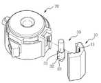
도 2는 도 1의 카메라 모듈의 분해 사시도;
도 3은 본 발명의 일실시예에 따른 렌즈배럴 어셈블리와 하우징이 결합되는 분해사시도;
도 4 내지 도 7은 본 발명의 일실시예에 따른 렌즈배럴과 압전액츄에이터 결합구조의 다양한 실시예; 및
도 8 내지 도 13은 본 발명의 일실시예에 따른 하우징과 압전액츄에이터 결합구조의 다양한 실시예이다.1 is a perspective view of a camera module according to an embodiment of the present invention;
FIG. 2 is an exploded perspective view of the camera module of FIG. 1; FIG.
3 is an exploded perspective view of a lens barrel assembly and a housing according to an embodiment of the present invention;
FIGS. 4 through 7 illustrate various embodiments of a lens barrel and a piezoelectric actuator coupling structure according to an embodiment of the present invention; And
8 to 13 are various embodiments of a housing and a piezoelectric actuator coupling structure according to an embodiment of the present invention.
본 발명의 일실시예의 목적, 특정한 장점들 및 신규한 특징들은 첨부된 도면들과 연관되어지는 이하의 상세한 설명과 구체적인 일실시예들로부터 더욱 명백해질 것이다. 본 명세서에서 각 도면의 구성요소들에 참조번호를 부가함에 있어서, 동일한 구성 요소들에 한해서는 비록 다른 도면상에 표시되더라도 가능한 한 동일한 번호를 가지도록 하고 있음에 유의하여야 한다. 또한, "일면", "타면", "제1", "제2" 등의 용어는 하나의 구성요소를 다른 구성요소로부터 구별하기 위해 사용되는 것으로, 구성요소가 상기 용어들에 의해 제한되는 것은 아니다. 이하, 본 발명의 일실시예를 설명함에 있어서, 본 발명의 일실시예의 요지를 불필요하게 흐릴 수 있는 관련된 공지 기술에 대한 상세한 설명은 생략한다.The objects, particular advantages and novel features of one embodiment of the present invention will become more apparent from the following detailed description taken in conjunction with the accompanying drawings, and from the specific embodiments thereof. It should be noted that, in the present specification, the reference numerals are added to the constituent elements of the drawings, and the same constituent elements have the same numerical numbers as much as possible even if they are displayed on different drawings. Also, the terms "one side," " first, "" first," " second, "and the like are used to distinguish one element from another, no. DETAILED DESCRIPTION OF THE PREFERRED EMBODIMENTS In the following description of the present invention, a detailed description of known arts which may unnecessarily obscure the gist of an embodiment of the present invention will be omitted.
이하, 첨부된 도면을 참조하여 본 발명의 구체적인 일실시예를 상세히 설명하기로 한다.
Hereinafter, embodiments of the present invention will be described in detail with reference to the accompanying drawings.
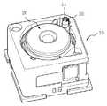
도 1은 본 발명의 일실시예에 따른 카메라 모듈의 사시도, 도 2는 도 1의 카메라 모듈의 분해 사시도이고, 도 3은 본 발명의 일실시예에 따른 렌즈배럴 어셈블리와 하우징이 결합되는 분해사시도이다.
FIG. 1 is a perspective view of a camera module according to an embodiment of the present invention, FIG. 2 is an exploded perspective view of the camera module of FIG. 1, and FIG. 3 is an exploded perspective view illustrating a lens barrel assembly and a housing according to an embodiment of the present invention. to be.
본 발명의 일실시예에 따른 카메라 모듈은, 적어도 하나 이상의 렌즈체를 포함하는 렌즈배럴(20), 상기 렌즈배럴(20)을 내부 공간에 수용하는 하우징(10), 상기 렌즈배럴(20)을 상기 하우징(10) 내부 공간에서 광축방향으로 구동시키도록 상기 하우징(10) 내측면(11)에 형성된 압전액추에이트를 포함하고, 상기 압전액츄에이터(30)는 상기 하우징(10) 내측면(11)과 자성체에 의한 인력으로 결합된다.
A camera module according to an embodiment of the present invention includes a
카메라 모듈은, 도 1 및 도 2에 도시된 바와 같이, 적어도 하나 이상의 렌즈체를 포함하고 있는 렌즈배럴(20), 렌즈배럴(20)을 수용하는 하우징(10), 렌즈배럴(20)을 광축방향으로 구동시키는 구동력 발생부인 압전액츄에이터(30)로 형성된다.
1 and 2, the camera module includes a
렌즈배럴(20)은 피사체를 촬상하는 적어도 하나 이상의 렌즈체가 내부에 수용될 수 있도록 중공의 원통형상일 수 있으며, 렌즈체는 광축을 따라 렌즈배럴(20) 내부에 구비된다. 렌즈배럴(20) 내에는 다양한 형태의 렌즈체가 삽입되어, 렌즈체를 통해 입사되는 광이 이미지센서(미도시)에 집광됨으로써 영상의 촬상이 이루어진다. 본 발명의 일실시예에 따른 렌즈배럴(20)은 그 형태 및 종류에 특별한 한정을 두지 않으며, 도시된 도면 및 상세한 설명은 하나의 실시예로써 당업자로부터 설계변경 가능한 범위의 렌즈배럴(20)의 구조 및 형태를 포함한다.
The
하우징(10)은 내부에 렌즈배럴(20)을 수용하도록 내부공간이 형성된다. 하우징(10)은 렌즈배럴(20)을 수용하며, 렌즈배럴(20)을 감싸도록 형성되어, 렌즈배럴(20)의 외부 충격으로부터 렌즈 기타 어셈블리를 보호하고, 기타 이물질의 유입을 방지함으로써 렌즈배럴(20)을 포함한 카메라 모듈의 구동성능을 안정적으로 유지 및 향상시킬 수 있다. 본 발명의 일실시예의 카메라 모듈은, 렌즈배럴(20)을 광축방향으로 구동시키기 위한 구동부가 압전액츄에이터(30)로 형성됨으로써 하우징(10) 내부공간에서 렌즈배럴(20)을 효과적으로 구동시킬 수 있다.
An inner space is formed in the
압전액츄에이터(30)는 하우징(10) 내부 공간에 형성되어, 렌즈배럴(20)을 광축방향으로 구동시킨다. 압전액츄에이터(30)는 전압을 인가하는 경우 압전액츄에이터(30)에 포함된 압전체(32)의 수축 또는 이완의 반복으로 발생된 구동력을 렌즈배럴(20)에 인가하게 된다. 압전체(32)는 외부로부터 기계적 변형이 가해지면 전기 분극이 나타나는 현상을 이용하는 소자로서, 반대로 전압을 걸면 소자가 이동하거나 힘이 발생하는 것이다. 압전체(32)에 전압이 인가되면 진동이 발생하며, 이러한 진동을 렌즈배럴(20)에 전달함으로써, 렌즈배럴(20)이 광축방향 상부 및 하부로 이동하는 것이다.
The
도 3에 도시된 바와 같이, 압전액츄에이터(30)는 하우징(10) 내부에 렌즈배럴(20) 및 대응되는 하우징(10)의 내측면(11)에 결합된다. 압전액츄에이터(30)는 하우징(10) 내측면(11)에 결합될 때, 본딩이나 접착방식이 아닌 자기력에 의한 인력으로 결합된다. 하우징(10) 내측면(11)에 본딩이나 기타 접착방식으로 압전액츄에이터(30)가 고정결합되는 경우, 압전액츄에이터(30)의 진동발생이 효과적으로 렌즈배럴(20)에 전달되지 못하는 문제점이 발생된다. 자기력에 의한 인력으로 결합되는 경우, 압전액츄에이터(30)의 발생되는 진동의 변위폭이 더 커질 수 있고, 이로 인한 렌즈배럴(20)에 전달되는 구동력의 효율 역시 매우 높아질 수 있어, 카메라 모듈의 구동 신뢰성 및 전력소비를 효과적으로 절감시킬 수 있을 뿐만 아니라, 압전액츄에이터(30) 자체구성의 내구성을 확보할 수 있는 이점이 있다.
3, the
또한, 압전액츄에이터(30)는 동시에, 렌즈배럴(20)에 밀착결합된다. 압전액츄에이터(30)가 렌즈배럴(20)에 밀착되어 결합됨으로써, 압전액츄에이터(30)의 상하구동력이 렌즈배럴(20)에 효과적으로 전달될 수 있다. 종래, 별도의 판스프링과 같은 부재로 압전액츄에이터(30)를 렌즈배럴(20)에 밀착시키는 예압구조의 경우, 별도의 부품이 삽입되어 공정이 복잡해지고, 생산성이 저감된다. 뿐만 아니라, 별도 부품에 의한 예압구조의 경우는 다수의 진동이 반복적으로 수행되는 경우, 압전액츄에이터(30)와 렌즈배럴(20)간의 예압구조가 느슨해지거나, 이탈되어 렌즈배럴(20)의 구동의 신뢰성이 급격히 저하될 수 있는 문제점이 있다. 따라서, 본 발명의 일실시예에서는 압전액츄에이터(30)와 하우징(10) 내측면(11)에 결합력의 확보 뿐만 아니라, 압전액츄에이터(30)와 렌즈배럴(20) 사이의 결합을 자기력을 이용하여 본딩과 같은 고정이 아닌 자기력에 의한 결합구조를 통해 효과적으로 압전체(32)의 구동력을 로드(31) 및 렌즈배럴(20)에 전달할 수 있다. 또한, 렌즈배럴(20)과 압전액츄에이터(30)의 결합면의 마찰을 효과적으로 구현함으로써, 렌즈배럴(20)의 구동성능의 신뢰성을 확보할 수 있는 예압구조를 형성할 수 있는 이점이 있다.
Further, the
압전액츄에이터(30)는 압전체(32)를 포함하도록 형성되며, 구체적으로는 도 2에 도시된 바와 같이, 렌즈배럴(20)의 광축방향의 구동력을 전달하는 로드(31) 및 로드(31)의 구동력을 발생시키기 위해 로드(31) 일단에 결합된 압전체(32)를 포함한다. 압전액츄에이터(30)의 구동력을 렌즈배럴(20)에 전달하기 위해, 로드(31)가 렌즈배럴(20)의 일측면에 마찰면이 형성되도록 밀착결합된다. 이 경우, 로드(31)는 하우징(10)의 내측면(11)에도 자기력에 의한 인력으로 결합된다. 카메라 모듈에 전압이 인가되어 압전체(32)가 구동되면, 구동력이 압전체(33)의 일단에 결합된 로드(31)에 전달되고, 로드(31)에 마찰면을 형성한 렌즈배럴(20)을 광축방향 상하부로 구동시킨다. 압전체(32)의 타단에는 중량체(33)가 더 결합될 수 있다. 중량체(33)는 압전체(32) 타단에 결합됨으로써, 압전체(32)가 구동하는 변위의 무게중심을 적절히 이동시켜, 보다 효과적으로 로드(31) 및 이와 결합된 렌즈배럴(20)을 구동시킬 수 있다.
The
이하에서는, 압전액츄에이터(30)와 렌즈배럴(20)의 결합구조 및 압전액츄에이터(30)와 하우징(10) 내측면(11)과의 결합구조에 관한 다양한 실시예를 도면을 참조하여 설명한다.
Hereinafter, various embodiments relating to a coupling structure between the
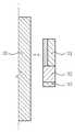
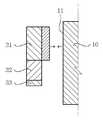
먼저, 도 4 내지 도 7은 본 발명의 일실시예에 따른 렌즈배럴과 압전액츄에이터가 자성체에 의한 인력으로 결합되기 위한 결합구조의 다양한 실시예를 나타내는 도면이다.
4 to 7 are views showing various embodiments of a coupling structure for coupling a lens barrel and a piezoelectric actuator according to an embodiment of the present invention with attraction by a magnetic body.
도 4에 도시된 바와 같이, 렌즈배럴(20)상에 자성부재(40)가 결합되고, 압전액츄에이터(30)의 로드(31)가 자성체 의한 인력으로 결합된다. 이 경우, 로드(31)는 압전액츄에이터(30)에 구비된 자성부재(40), 예를 들면, 자석 등, 와 인력으로 결합되도록 금속재질로 형성된다. 여기서, 자성부재(40)는 렌즈배럴(20) 외측면에 별도의 부재로 결합될 수 있지만, 도 5에 도시된 바와 같이, 렌즈배럴(20) 외측면에 일체로 형성될 수 있다. 렌즈배럴(20)을 제조하는 과정에서 압전액츄에이터(30)와 결합되는 외측면상을 자성부재(40)로 일체 성형하는 것이다.
4, the
또한, 도 6에 도시된 바와 같이, 자성부재(40)에 인력으로 결합되는 렌즈배럴(20) 외측면의 재질에 대응되도록 압전액츄에이터(30)상에 자성부재(40)를 별도로 결합할 수 있다. 도시된 도면은 압전액츄에이터(30)의 로드(31)의 외측면에 자성부재(40)를 결합한 것이다. 렌즈베럴(20)은 사출물로 형성될 수 있으며, 이 경우에는 자성부재(40)에 의해 인력이 발생되도록 대응되는 위치에 금속 등의 재질을 형성할 수 있다. 여기서도, 자성부재(40)는 로드(31)와 별도 부재로 결합될 수 있지만, 도 7에 도시된 바와 같이, 압전액츄에이터(30)의 제조공정에서 사출성형 등을 통해 자성부재(40)를 일체로 형성할 수 있다.
6, the
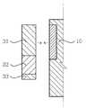
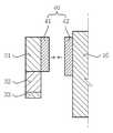
도 8에 도시된 바와 같이, 렌즈배럴(20)의 외측면과 압전액츄에이터(30)상에 각각 자성부재(40)를 결합하고, 각 자성부재(40)를 서로 다른 극을 갖도록 제1 자성부재(41)와 제2 자성부재(42)를 형성함으로써 자성체에 의한 인력으로 양 부재를 결합시킬 수 있다. 예를 들어, 어느 한 측면의 제1 자성부재(41)가 N극으로 형성된 경우, 대응되는 제2 자성부재(42)는 S극으로 형성하여 상호 인력이 발생되도록 배치하는 것이다.
8, the
다음, 도 9 내지 도 13은 본 발명의 일실시예에 따른 하우징과 압전액츄에이터를 자성체의 인력으로 결합한 결합구조의 다양한 실시예를 나타내는 도면이다.
9 to 13 are views showing various embodiments of a coupling structure in which a housing and a piezoelectric actuator according to an embodiment of the present invention are coupled by attraction of a magnetic body.
상술한 바와 같이, 압전액츄에이터(30)와 하우징(10)의 내측면(11)에 본딩공정으로 결합하는 경우, 압전액츄에이터(30)의 압전체(32)의 의해 발생되는 변위를 효과적으로 렌즈배럴(20)에 전달하기 어려운 문제가 있었다. 압전액츄에이터(30)가 하우징(10) 내측면(11)에 본딩으로 결합되는 경우, 플렉서블한 탄성접착제 등으로 결합된다고 하더라도, 압전체(32)의 진동 변위폭이 제한됨으로써, 렌즈배럴(20)의 광축방향 구동에 필요 이상의 전압이 인가되거나, 렌즈배럴(20)의 광축방향 변위의 제어상의 신뢰성이 저하될 수 있는 문제점이 발생된다. 그러므로, 하우징(10) 내측면(11)에 압전액츄에이터(30)를 자성부재(40)의 인력에 의한 결합구조를 형성하여, 압전액츄에이터(30)의 변위폭을 압전체(32)의 변위폭과 실질적으로 동일하게 구현함으로써, 압전체(32)로 부터 구동력을 전달받는 렌즈배럴(20) 구동변위의 신뢰성도 효과적으로 확보할 수 있는 것이다.
The displacement generated by the
먼저, 도 9에 도시된 바와 같이, 하우징(10) 내측면(11)상에 별도의 자성부재(40)를 결합시켜, 자성부재(40)와 대응되는 압전액츄에이터(30)가 상호 인력으로 결합될 수 있다. 또한, 도 10에 도시된 바와 같이, 자성부재(40)는 하우징(10)의 내측면(11)에 일체로 형성될 수 있다. 하우징(10) 내측면(11)을 인서트 사출성형으로 제조하여 자성부재(40)와 일체로 하우징(10)을 제조할 수 있다.
9, a separate
도 11에 도시된 바와 같이, 하우징(10) 내측면(11)에 대응되는 압전액츄에이터(30)의 외측면상에 별도의 자성부재(40)를 결합할 수 있다. 하우징(10)은 사출물로 형성될 수 있으며, 이 경우에는 자성부재(40)에 의해 인력이 발생되도록 대응되는 위치에 금속 등의 재질을 형성할 수 있다. 또는, 도 12에 도시된 바와 같이, 압전액츄에이터(30)의 로드(31)상에 자성부재(40)를 일체로 성형함으로써, 제조공정을 통해 이러한 실시예를 보다 효과적으로 구현할 수 있다.
An additional
도 13에 도시된 바와 같이, 하우징(10) 내측면(11)과 압전액츄에이터(30)의 대응 외측면상에 각각 자성부재(40)를 결합하고, 각 자성부재(40)를 서로 다른 극을 갖도록 제1 자성부재(41)와 제2 자성부재(42)를 형성함으로써 자성체에 의한 인력으로 양 부재를 결합시킬 수 있다. 예를 들어, 어느 한 측면의 제1 자성부재(41)가 N극으로 형성된 경우, 대응되는 제2 자성부재(42)는 S극으로 형성하여 상호 인력이 발생되도록 배치하는 것이다.
The
이상 본 발명을 구체적인 실시예를 통하여 상세히 설명하였으나, 이는 본 발명을 구체적으로 설명하기 위한 것으로, 본 발명의 일실시예는 이에 한정되지 않으며, 본 발명의 일실시예의 기술적 사상 내에서 당해 분야의 통상의 지식을 가진 자에 의해 그 변형이나 개량이 가능함은 명백하다고 할 것이다.While the present invention has been particularly shown and described with reference to exemplary embodiments thereof, it is to be understood that the invention is not limited to the disclosed exemplary embodiments, but, on the contrary, It will be apparent that modifications and improvements can be made by those skilled in the art.
본 발명의 일실시예의 단순한 변형 내지 변경은 모두 본 발명의 일실시예의 영역에 속하는 것으로 본 발명의 일실시예의 구체적인 보호 범위는 첨부된 특허청구범위에 의하여 명확해질 것이다.
It will be understood by those of ordinary skill in the art that various changes in form and details may be made therein without departing from the spirit and scope of the invention as defined by the appended claims.
10: 하우징11: 내측면
20: 렌즈배럴30: 압전액츄에이터
31: 로드32: 압전체
33: 중량체40: 자성부재
41: 제1 자성부재42: 제2 자성부재10: housing 11: inner side
20: lens barrel 30: piezoelectric actuator
31: rod 32:
33: weight body 40: magnetic member
41: first magnetic member 42: second magnetic member
Claims (13)
Translated fromKorean상기 렌즈배럴을 내부 공간에 수용하는 하우징;
상기 렌즈배럴을 상기 하우징 내부 공간에서 광축방향으로 구동시키도록 상기 하우징 내측면에 형성된 압전액츄에이터를 포함하고,
상기 압전액츄에이터는 상기 하우징 내측면과 자기력에 의해 결합된 카메라 모듈.
A lens barrel including at least one lens body;
A housing housing the lens barrel in an inner space;
And a piezoelectric actuator formed on the inner surface of the housing to drive the lens barrel in the optical axis direction in the housing inner space,
And the piezoelectric actuator is coupled to a side surface of the housing by magnetic force.
상기 하우징 내측면에 자성체에 의한 인력으로 결합되도록, 상기 압전액츄에이터는 자성부재가 결합된 카메라 모듈.
The method according to claim 1,
Wherein the piezoelectric actuator is coupled to a magnetic member by a magnetic force by a magnetic body on a side surface of the housing.
상기 하우징 내측면은 상기 압전액츄에이터가 자성체에 의한 인력으로 결합되도록, 자성부재가 결합된 카메라 모듈.
The method according to claim 1,
And the inner surface of the housing is coupled with a magnetic member such that the piezoelectric actuator is coupled by attraction by a magnetic body.
상기 압전액츄에이터는,
상기 렌즈배럴의 광축방향의 구동력을 전달하는 로드; 및
상기 로드의 구동력을 발생시키기 위해 상기 로드 일단에 결합된 압전체;를 포함하고,
상기 로드가 상기 자성부재로 형성된 카메라 모듈.
The method of claim 2,
In the piezoelectric actuator,
A rod for transmitting driving force in the optical axis direction of the lens barrel; And
And a piezoelectric body coupled to one end of the rod to generate a driving force of the rod,
Wherein the rod is formed of the magnetic member.
상기 압전액츄에이터는,
상기 렌즈배럴의 광축방향의 구동력을 전달하는 로드; 및
상기 로드의 구동력을 발생시키기 위해 상기 로드 일단에 결합된 압전체;를 포함하고,
상기 로드는 상기 하우징 내측면에 대응되는 측면에 자성부재가 결합된 카메라 모듈.
The method of claim 2,
In the piezoelectric actuator,
A rod for transmitting driving force in the optical axis direction of the lens barrel; And
And a piezoelectric body coupled to one end of the rod to generate a driving force of the rod,
Wherein the rod has a magnetic member coupled to a side surface corresponding to a side surface of the housing.
상기 로드와 상기 자성부재는 일체로 형성된 카메라 모듈.
The method of claim 5,
Wherein the rod and the magnetic member are integrally formed.
상기 압전액츄에이터는,
상기 로드가 형성된 압전체 일단과 대응되는 상기 압전체 타단에 형성된 중량체;를 더 포함하는 카메라 모듈.
The method of claim 4,
In the piezoelectric actuator,
And a weight formed on the other end of the piezoelectric body corresponding to one end of the piezoelectric body on which the rod is formed.
상기 자성부재는 상기 하우징에 인서트 사출성형으로 일체로 형성된 카메라 모듈.
The method of claim 4,
Wherein the magnetic member is formed integrally with the housing by insert injection molding.
상기 압전액츄에이터와 상기 하우징 내측면이 자성체에 의한 인력으로 결합되도록,
상기 압전액츄에이터 및 상기 하우징 내측면이 마주보도록, 각각 제1 자성부재 및 제2 자성부재가 결합되고,
상기 제1 자성부재 및 상기 제2 자성부재는 상호 인력이 작용하도록 자석의 N극 또는 S극이 상호 다른 극으로 형성된 카메라 모듈.
The method according to claim 1,
The piezoelectric actuator and the inner side surface of the housing are coupled by a magnetic force,
A first magnetic member and a second magnetic member are coupled to each other so that the piezoelectric actuator and the inner surface of the housing face each other,
Wherein the first magnetic member and the second magnetic member are formed such that N poles or S poles of the magnets are mutually different poles so that mutual attraction acts.
상히 압전액츄에이터는 상기 렌즈배럴 외측면에 결합되며,
상기 압전액츄에이터 및 상기 렌즈배럴 외측면은 자성체의 의한 인력으로 결합되는 카메라 모듈.
The method according to claim 1,
The piezoelectric actuator is coupled to the outer surface of the lens barrel,
Wherein the piezoelectric actuator and the outer surface of the lens barrel are coupled by attraction by a magnetic body.
상기 압전액츄에이터는
상기 압전액츄에이터는,
상기 렌즈배럴의 광축방향의 구동력을 전달하는 로드; 및
상기 로드의 구동력을 발생시키기 위해 상기 로드 일단에 결합된 압전체;를 포함하고,
상기 로드는 상기 렌즈배럴 외측면에 대응되는 측면에 자성부재가 결합된 카메라 모듈.
The method of claim 10,
The piezoelectric actuator
In the piezoelectric actuator,
A rod for transmitting driving force in the optical axis direction of the lens barrel; And
And a piezoelectric body coupled to one end of the rod to generate a driving force of the rod,
Wherein the rod has a magnetic member coupled to a side surface corresponding to the outer surface of the lens barrel.
상기 압전액츄에이터는 상기 렌즈배럴 외측면에 대응되는 외측면에 자성부재가 결합된 카메라 모듈.
The method of claim 10,
Wherein the piezoelectric actuator has a magnetic member coupled to an outer surface corresponding to an outer surface of the lens barrel.
상기 압전액츄에이터와 상기 렌즈배럴 외측면이 자성체에 의한 인력으로 결합되도록,
상기 압전액츄에이터 및 상기 렌즈배럴 외측면이 마주보도록, 각각 제1 자성부재 및 제2 자성부재가 결합되고,
상기 제1 자성부재 및 상기 제2 자성부재는 상호 인력이 작용하도록 자석의 N극 또는 S극이 상호 다른 극으로 형성된 카메라 모듈.The method of claim 10,
The piezoelectric actuator and the outer surface of the lens barrel are coupled to each other by a magnetic force,
A first magnetic member and a second magnetic member are coupled to the piezoelectric actuator and the outer surface of the lens barrel so as to face each other,
Wherein the first magnetic member and the second magnetic member are formed such that N poles or S poles of the magnets are mutually different poles so that mutual attraction acts.
Priority Applications (3)
| Application Number | Priority Date | Filing Date | Title |
|---|---|---|---|
| KR1020140175275AKR20160069381A (en) | 2014-12-08 | 2014-12-08 | Camera Module |
| US14/949,098US20160161828A1 (en) | 2014-12-08 | 2015-11-23 | Camera module |
| CN201510896511.0ACN105676568A (en) | 2014-12-08 | 2015-12-08 | Camera module |
Applications Claiming Priority (1)
| Application Number | Priority Date | Filing Date | Title |
|---|---|---|---|
| KR1020140175275AKR20160069381A (en) | 2014-12-08 | 2014-12-08 | Camera Module |
Publications (1)
| Publication Number | Publication Date |
|---|---|
| KR20160069381Atrue KR20160069381A (en) | 2016-06-16 |
Family
ID=56094226
Family Applications (1)
| Application Number | Title | Priority Date | Filing Date |
|---|---|---|---|
| KR1020140175275ACeasedKR20160069381A (en) | 2014-12-08 | 2014-12-08 | Camera Module |
Country Status (3)
| Country | Link |
|---|---|
| US (1) | US20160161828A1 (en) |
| KR (1) | KR20160069381A (en) |
| CN (1) | CN105676568A (en) |
Cited By (1)
| Publication number | Priority date | Publication date | Assignee | Title |
|---|---|---|---|---|
| WO2024054076A1 (en)* | 2022-09-07 | 2024-03-14 | 엘지이노텍 주식회사 | Camera module and optical device comprising same |
Families Citing this family (29)
| Publication number | Priority date | Publication date | Assignee | Title |
|---|---|---|---|---|
| US11956544B2 (en)* | 2016-03-11 | 2024-04-09 | Apple Inc. | Optical image stabilization with voice coil motor for moving image sensor |
| SG11201807830UA (en) | 2016-03-11 | 2018-10-30 | Apple Inc | Optical image stabilization with voice coil motor for moving image sensor |
| US10437023B2 (en) | 2016-03-28 | 2019-10-08 | Apple Inc. | Folded lens system with three refractive lenses |
| KR102587749B1 (en)* | 2016-08-24 | 2023-10-12 | 삼성전자주식회사 | Apparatus for Adjusting Auto Focus and Electronic Apparatus being Capable of Auto Focus |
| US10890734B1 (en) | 2017-03-29 | 2021-01-12 | Apple Inc. | Camera actuator for lens and sensor shifting |
| CN108957678B (en)* | 2017-05-19 | 2021-10-15 | 台湾东电化股份有限公司 | Optical drive mechanism |
| US10585261B2 (en)* | 2017-05-19 | 2020-03-10 | Tdk Taiwan Corp. | Optical driving mechanism |
| WO2018219324A1 (en)* | 2017-06-02 | 2018-12-06 | 宁波舜宇光电信息有限公司 | Driving assembly, imaging module and electronic device thereof |
| US10863094B2 (en) | 2017-07-17 | 2020-12-08 | Apple Inc. | Camera with image sensor shifting |
| JP7122555B2 (en)* | 2018-01-26 | 2022-08-22 | パナソニックIpマネジメント株式会社 | Actuator for optical equipment and lens barrel provided with the same |
| US11122205B1 (en) | 2018-09-14 | 2021-09-14 | Apple Inc. | Camera actuator assembly with sensor shift flexure arrangement |
| CN211878283U (en)* | 2019-10-25 | 2020-11-06 | 台湾东电化股份有限公司 | Optical element drive mechanism |
| CN111212209B (en)* | 2020-02-28 | 2021-11-16 | 维沃移动通信有限公司 | Camera module and electronic equipment |
| CN216160896U (en)* | 2020-06-23 | 2022-04-01 | 诚瑞光学(常州)股份有限公司 | Lens module |
| CN114077031B (en)* | 2020-08-12 | 2023-03-10 | 华为技术有限公司 | Ultrasonic piezoelectric motor, camera module and electronic equipment |
| CN114114596A (en)* | 2020-08-28 | 2022-03-01 | 台湾东电化股份有限公司 | Optical element driving mechanism |
| US11575835B2 (en) | 2020-09-24 | 2023-02-07 | Apple Inc. | Multi-axis image sensor shifting system |
| CN114624845A (en)* | 2020-11-26 | 2022-06-14 | 格科微电子(上海)有限公司 | Camera module and digital device |
| CN114624847A (en)* | 2020-11-26 | 2022-06-14 | 格科微电子(上海)有限公司 | Camera module |
| CN114563854A (en)* | 2020-11-26 | 2022-05-31 | 格科微电子(上海)有限公司 | Camera module |
| CN114915709B (en)* | 2021-02-10 | 2023-09-19 | 宁波舜宇光电信息有限公司 | Sleeve type optical actuator, corresponding camera module and terminal equipment |
| CN115103086B (en)* | 2021-03-04 | 2023-04-18 | 宁波舜宇光电信息有限公司 | Sleeve assembly and assembly method of corresponding telescopic camera module |
| CN216817056U (en)* | 2021-03-29 | 2022-06-24 | 台湾东电化股份有限公司 | Optical element drive mechanism |
| CN117203583A (en)* | 2021-04-09 | 2023-12-08 | 宁波舜宇光电信息有限公司 | Periscope type camera shooting module and variable-focus camera shooting module |
| WO2022228112A1 (en)* | 2021-04-26 | 2022-11-03 | 宁波舜宇光电信息有限公司 | Camera module |
| CN117501176A (en)* | 2021-04-30 | 2024-02-02 | 宁波舜宇光电信息有限公司 | Camera module |
| CN115379074B (en)* | 2021-05-18 | 2024-07-12 | 宁波舜宇光电信息有限公司 | Optical actuator and corresponding camera module |
| CN115484359B (en)* | 2021-06-15 | 2024-04-16 | 宁波舜宇光电信息有限公司 | Lens assembly, camera module and assembly method thereof |
| KR20230022599A (en)* | 2021-08-09 | 2023-02-16 | 엘지이노텍 주식회사 | Camera actuator and camera device comprising the same |
Citations (1)
| Publication number | Priority date | Publication date | Assignee | Title |
|---|---|---|---|---|
| US20100150545A1 (en) | 2006-10-27 | 2010-06-17 | Sony Corporation | Camera module |
Family Cites Families (7)
| Publication number | Priority date | Publication date | Assignee | Title |
|---|---|---|---|---|
| WO2008038636A1 (en)* | 2006-09-26 | 2008-04-03 | Nec Tokin Corporation | Lens module |
| JP2011008121A (en)* | 2009-06-26 | 2011-01-13 | Sony Corp | Varifocal lens, camera module, and electronic equipment |
| KR101158222B1 (en)* | 2010-12-16 | 2012-06-19 | 삼성전기주식회사 | Lens actuating module |
| JP5880021B2 (en)* | 2011-03-18 | 2016-03-08 | Tdk株式会社 | Lens drive device |
| US8606095B2 (en)* | 2011-10-18 | 2013-12-10 | Samsung Electro-Mechanics Co., Ltd. | Camera module having auto-focus apparatus |
| KR20130127780A (en)* | 2012-05-15 | 2013-11-25 | 삼성전기주식회사 | Camera module |
| WO2015001954A1 (en)* | 2013-07-04 | 2015-01-08 | コニカミノルタ株式会社 | Lens driving apparatus |
- 2014
- 2014-12-08KRKR1020140175275Apatent/KR20160069381A/ennot_activeCeased
- 2015
- 2015-11-23USUS14/949,098patent/US20160161828A1/ennot_activeAbandoned
- 2015-12-08CNCN201510896511.0Apatent/CN105676568A/enactivePending
Patent Citations (1)
| Publication number | Priority date | Publication date | Assignee | Title |
|---|---|---|---|---|
| US20100150545A1 (en) | 2006-10-27 | 2010-06-17 | Sony Corporation | Camera module |
Cited By (1)
| Publication number | Priority date | Publication date | Assignee | Title |
|---|---|---|---|---|
| WO2024054076A1 (en)* | 2022-09-07 | 2024-03-14 | 엘지이노텍 주식회사 | Camera module and optical device comprising same |
Also Published As
| Publication number | Publication date |
|---|---|
| US20160161828A1 (en) | 2016-06-09 |
| CN105676568A (en) | 2016-06-15 |
Similar Documents
| Publication | Publication Date | Title |
|---|---|---|
| KR20160069381A (en) | Camera Module | |
| KR102183393B1 (en) | Lens drive device, camera device, and electronic device | |
| US7990625B2 (en) | Camera module | |
| US7990636B2 (en) | Lens actuating module | |
| KR101044109B1 (en) | Lens drive module | |
| US7936527B2 (en) | Auto focus lens module with piezoelectric actuator | |
| JP4792511B2 (en) | The camera module | |
| WO2016152160A1 (en) | Lens drive device, camera module, and camera-equipped device | |
| US9063389B2 (en) | Camera module | |
| JP2009058601A (en) | Lens driving device, imaging device, and mobile terminal | |
| TWI599810B (en) | Camera module | |
| US20150015954A1 (en) | Camera module | |
| JP4317508B2 (en) | Camera module and portable terminal equipped with the camera module | |
| KR101234952B1 (en) | Lens driving mechanism for digital camera | |
| US8606095B2 (en) | Camera module having auto-focus apparatus | |
| WO2015001952A1 (en) | Lens driving apparatus | |
| EP1970741A1 (en) | Miniature lens focusing mechanism | |
| KR200460569Y1 (en) | Auto focus lens module with piezoelectric actuator | |
| JP6948102B2 (en) | Linear drive, camera and electronic equipment | |
| CN105700104A (en) | Camera module | |
| JPWO2012147320A1 (en) | Imaging apparatus and manufacturing method of imaging apparatus | |
| JP6753756B2 (en) | Drive unit and camera module | |
| JP2010098902A (en) | Drive device and image capturing apparatus | |
| CN115668961A (en) | Camera Modules and Optics | |
| KR101070924B1 (en) | Linear driving device |
Legal Events
| Date | Code | Title | Description |
|---|---|---|---|
| PA0109 | Patent application | Patent event code:PA01091R01D Comment text:Patent Application Patent event date:20141208 | |
| PG1501 | Laying open of application | ||
| PA0201 | Request for examination | Patent event code:PA02012R01D Patent event date:20171130 Comment text:Request for Examination of Application Patent event code:PA02011R01I Patent event date:20141208 Comment text:Patent Application | |
| E902 | Notification of reason for refusal | ||
| PE0902 | Notice of grounds for rejection | Comment text:Notification of reason for refusal Patent event date:20190531 Patent event code:PE09021S01D | |
| E601 | Decision to refuse application | ||
| PE0601 | Decision on rejection of patent | Patent event date:20190911 Comment text:Decision to Refuse Application Patent event code:PE06012S01D Patent event date:20190531 Comment text:Notification of reason for refusal Patent event code:PE06011S01I |