KR20160067447A - Display apparatus - Google Patents
Display apparatusDownload PDFInfo
- Publication number
- KR20160067447A KR20160067447AKR1020140172858AKR20140172858AKR20160067447AKR 20160067447 AKR20160067447 AKR 20160067447AKR 1020140172858 AKR1020140172858 AKR 1020140172858AKR 20140172858 AKR20140172858 AKR 20140172858AKR 20160067447 AKR20160067447 AKR 20160067447A
- Authority
- KR
- South Korea
- Prior art keywords
- light
- guide plate
- light guide
- light source
- dimensional
- Prior art date
- Legal status (The legal status is an assumption and is not a legal conclusion. Google has not performed a legal analysis and makes no representation as to the accuracy of the status listed.)
- Withdrawn
Links
Images


Classifications
- G—PHYSICS
- G02—OPTICS
- G02B—OPTICAL ELEMENTS, SYSTEMS OR APPARATUS
- G02B6/00—Light guides; Structural details of arrangements comprising light guides and other optical elements, e.g. couplings
- G02B6/0001—Light guides; Structural details of arrangements comprising light guides and other optical elements, e.g. couplings specially adapted for lighting devices or systems
- G02B6/0011—Light guides; Structural details of arrangements comprising light guides and other optical elements, e.g. couplings specially adapted for lighting devices or systems the light guides being planar or of plate-like form
- G02B6/0081—Mechanical or electrical aspects of the light guide and light source in the lighting device peculiar to the adaptation to planar light guides, e.g. concerning packaging
- G02B6/0086—Positioning aspects
- G02B6/009—Positioning aspects of the light source in the package
- G—PHYSICS
- G02—OPTICS
- G02F—OPTICAL DEVICES OR ARRANGEMENTS FOR THE CONTROL OF LIGHT BY MODIFICATION OF THE OPTICAL PROPERTIES OF THE MEDIA OF THE ELEMENTS INVOLVED THEREIN; NON-LINEAR OPTICS; FREQUENCY-CHANGING OF LIGHT; OPTICAL LOGIC ELEMENTS; OPTICAL ANALOGUE/DIGITAL CONVERTERS
- G02F1/00—Devices or arrangements for the control of the intensity, colour, phase, polarisation or direction of light arriving from an independent light source, e.g. switching, gating or modulating; Non-linear optics
- G02F1/01—Devices or arrangements for the control of the intensity, colour, phase, polarisation or direction of light arriving from an independent light source, e.g. switching, gating or modulating; Non-linear optics for the control of the intensity, phase, polarisation or colour
- G02F1/13—Devices or arrangements for the control of the intensity, colour, phase, polarisation or direction of light arriving from an independent light source, e.g. switching, gating or modulating; Non-linear optics for the control of the intensity, phase, polarisation or colour based on liquid crystals, e.g. single liquid crystal display cells
- G02F1/133—Constructional arrangements; Operation of liquid crystal cells; Circuit arrangements
- G02F1/1333—Constructional arrangements; Manufacturing methods
- G02F1/1335—Structural association of cells with optical devices, e.g. polarisers or reflectors
- G02F1/1336—Illuminating devices
- G02F1/133602—Direct backlight
- G02F1/133603—Direct backlight with LEDs
- G—PHYSICS
- G02—OPTICS
- G02B—OPTICAL ELEMENTS, SYSTEMS OR APPARATUS
- G02B6/00—Light guides; Structural details of arrangements comprising light guides and other optical elements, e.g. couplings
- G02B6/0001—Light guides; Structural details of arrangements comprising light guides and other optical elements, e.g. couplings specially adapted for lighting devices or systems
- G02B6/0011—Light guides; Structural details of arrangements comprising light guides and other optical elements, e.g. couplings specially adapted for lighting devices or systems the light guides being planar or of plate-like form
- G02B6/0013—Means for improving the coupling-in of light from the light source into the light guide
- G02B6/0023—Means for improving the coupling-in of light from the light source into the light guide provided by one optical element, or plurality thereof, placed between the light guide and the light source, or around the light source
- G02B6/0025—Diffusing sheet or layer; Prismatic sheet or layer
- G—PHYSICS
- G02—OPTICS
- G02B—OPTICAL ELEMENTS, SYSTEMS OR APPARATUS
- G02B6/00—Light guides; Structural details of arrangements comprising light guides and other optical elements, e.g. couplings
- G02B6/0001—Light guides; Structural details of arrangements comprising light guides and other optical elements, e.g. couplings specially adapted for lighting devices or systems
- G02B6/0011—Light guides; Structural details of arrangements comprising light guides and other optical elements, e.g. couplings specially adapted for lighting devices or systems the light guides being planar or of plate-like form
- G02B6/0013—Means for improving the coupling-in of light from the light source into the light guide
- G02B6/0023—Means for improving the coupling-in of light from the light source into the light guide provided by one optical element, or plurality thereof, placed between the light guide and the light source, or around the light source
- G02B6/0031—Reflecting element, sheet or layer
- G—PHYSICS
- G02—OPTICS
- G02B—OPTICAL ELEMENTS, SYSTEMS OR APPARATUS
- G02B6/00—Light guides; Structural details of arrangements comprising light guides and other optical elements, e.g. couplings
- G02B6/0001—Light guides; Structural details of arrangements comprising light guides and other optical elements, e.g. couplings specially adapted for lighting devices or systems
- G02B6/0011—Light guides; Structural details of arrangements comprising light guides and other optical elements, e.g. couplings specially adapted for lighting devices or systems the light guides being planar or of plate-like form
- G02B6/0066—Light guides; Structural details of arrangements comprising light guides and other optical elements, e.g. couplings specially adapted for lighting devices or systems the light guides being planar or of plate-like form characterised by the light source being coupled to the light guide
- G02B6/0068—Arrangements of plural sources, e.g. multi-colour light sources
- G—PHYSICS
- G02—OPTICS
- G02B—OPTICAL ELEMENTS, SYSTEMS OR APPARATUS
- G02B6/00—Light guides; Structural details of arrangements comprising light guides and other optical elements, e.g. couplings
- G02B6/0001—Light guides; Structural details of arrangements comprising light guides and other optical elements, e.g. couplings specially adapted for lighting devices or systems
- G02B6/0011—Light guides; Structural details of arrangements comprising light guides and other optical elements, e.g. couplings specially adapted for lighting devices or systems the light guides being planar or of plate-like form
- G02B6/0081—Mechanical or electrical aspects of the light guide and light source in the lighting device peculiar to the adaptation to planar light guides, e.g. concerning packaging
- G02B6/0086—Positioning aspects
- G02B6/0088—Positioning aspects of the light guide or other optical sheets in the package
- G—PHYSICS
- G02—OPTICS
- G02F—OPTICAL DEVICES OR ARRANGEMENTS FOR THE CONTROL OF LIGHT BY MODIFICATION OF THE OPTICAL PROPERTIES OF THE MEDIA OF THE ELEMENTS INVOLVED THEREIN; NON-LINEAR OPTICS; FREQUENCY-CHANGING OF LIGHT; OPTICAL LOGIC ELEMENTS; OPTICAL ANALOGUE/DIGITAL CONVERTERS
- G02F1/00—Devices or arrangements for the control of the intensity, colour, phase, polarisation or direction of light arriving from an independent light source, e.g. switching, gating or modulating; Non-linear optics
- G02F1/01—Devices or arrangements for the control of the intensity, colour, phase, polarisation or direction of light arriving from an independent light source, e.g. switching, gating or modulating; Non-linear optics for the control of the intensity, phase, polarisation or colour
- G02F1/13—Devices or arrangements for the control of the intensity, colour, phase, polarisation or direction of light arriving from an independent light source, e.g. switching, gating or modulating; Non-linear optics for the control of the intensity, phase, polarisation or colour based on liquid crystals, e.g. single liquid crystal display cells
- G02F1/133—Constructional arrangements; Operation of liquid crystal cells; Circuit arrangements
- G02F1/1333—Constructional arrangements; Manufacturing methods
- G02F1/1335—Structural association of cells with optical devices, e.g. polarisers or reflectors
- G02F1/133524—Light-guides, e.g. fibre-optic bundles, louvered or jalousie light-guides
- G—PHYSICS
- G02—OPTICS
- G02F—OPTICAL DEVICES OR ARRANGEMENTS FOR THE CONTROL OF LIGHT BY MODIFICATION OF THE OPTICAL PROPERTIES OF THE MEDIA OF THE ELEMENTS INVOLVED THEREIN; NON-LINEAR OPTICS; FREQUENCY-CHANGING OF LIGHT; OPTICAL LOGIC ELEMENTS; OPTICAL ANALOGUE/DIGITAL CONVERTERS
- G02F1/00—Devices or arrangements for the control of the intensity, colour, phase, polarisation or direction of light arriving from an independent light source, e.g. switching, gating or modulating; Non-linear optics
- G02F1/01—Devices or arrangements for the control of the intensity, colour, phase, polarisation or direction of light arriving from an independent light source, e.g. switching, gating or modulating; Non-linear optics for the control of the intensity, phase, polarisation or colour
- G02F1/13—Devices or arrangements for the control of the intensity, colour, phase, polarisation or direction of light arriving from an independent light source, e.g. switching, gating or modulating; Non-linear optics for the control of the intensity, phase, polarisation or colour based on liquid crystals, e.g. single liquid crystal display cells
- G02F1/133—Constructional arrangements; Operation of liquid crystal cells; Circuit arrangements
- G02F1/1333—Constructional arrangements; Manufacturing methods
- G02F1/1335—Structural association of cells with optical devices, e.g. polarisers or reflectors
- G02F1/133553—Reflecting elements
- G—PHYSICS
- G02—OPTICS
- G02F—OPTICAL DEVICES OR ARRANGEMENTS FOR THE CONTROL OF LIGHT BY MODIFICATION OF THE OPTICAL PROPERTIES OF THE MEDIA OF THE ELEMENTS INVOLVED THEREIN; NON-LINEAR OPTICS; FREQUENCY-CHANGING OF LIGHT; OPTICAL LOGIC ELEMENTS; OPTICAL ANALOGUE/DIGITAL CONVERTERS
- G02F1/00—Devices or arrangements for the control of the intensity, colour, phase, polarisation or direction of light arriving from an independent light source, e.g. switching, gating or modulating; Non-linear optics
- G02F1/01—Devices or arrangements for the control of the intensity, colour, phase, polarisation or direction of light arriving from an independent light source, e.g. switching, gating or modulating; Non-linear optics for the control of the intensity, phase, polarisation or colour
- G02F1/13—Devices or arrangements for the control of the intensity, colour, phase, polarisation or direction of light arriving from an independent light source, e.g. switching, gating or modulating; Non-linear optics for the control of the intensity, phase, polarisation or colour based on liquid crystals, e.g. single liquid crystal display cells
- G02F1/133—Constructional arrangements; Operation of liquid crystal cells; Circuit arrangements
- G02F1/1333—Constructional arrangements; Manufacturing methods
- G02F1/1335—Structural association of cells with optical devices, e.g. polarisers or reflectors
- G02F1/1336—Illuminating devices
- G02F1/133602—Direct backlight
- G02F1/133606—Direct backlight including a specially adapted diffusing, scattering or light controlling members
- G—PHYSICS
- G02—OPTICS
- G02F—OPTICAL DEVICES OR ARRANGEMENTS FOR THE CONTROL OF LIGHT BY MODIFICATION OF THE OPTICAL PROPERTIES OF THE MEDIA OF THE ELEMENTS INVOLVED THEREIN; NON-LINEAR OPTICS; FREQUENCY-CHANGING OF LIGHT; OPTICAL LOGIC ELEMENTS; OPTICAL ANALOGUE/DIGITAL CONVERTERS
- G02F1/00—Devices or arrangements for the control of the intensity, colour, phase, polarisation or direction of light arriving from an independent light source, e.g. switching, gating or modulating; Non-linear optics
- G02F1/01—Devices or arrangements for the control of the intensity, colour, phase, polarisation or direction of light arriving from an independent light source, e.g. switching, gating or modulating; Non-linear optics for the control of the intensity, phase, polarisation or colour
- G02F1/13—Devices or arrangements for the control of the intensity, colour, phase, polarisation or direction of light arriving from an independent light source, e.g. switching, gating or modulating; Non-linear optics for the control of the intensity, phase, polarisation or colour based on liquid crystals, e.g. single liquid crystal display cells
- G02F1/133—Constructional arrangements; Operation of liquid crystal cells; Circuit arrangements
- G02F1/1333—Constructional arrangements; Manufacturing methods
- G02F1/1335—Structural association of cells with optical devices, e.g. polarisers or reflectors
- G02F1/1336—Illuminating devices
- G02F1/133615—Edge-illuminating devices, i.e. illuminating from the side
Landscapes
- Physics & Mathematics (AREA)
- Nonlinear Science (AREA)
- General Physics & Mathematics (AREA)
- Optics & Photonics (AREA)
- Mathematical Physics (AREA)
- Chemical & Material Sciences (AREA)
- Crystallography & Structural Chemistry (AREA)
- Planar Illumination Modules (AREA)
- Liquid Crystal (AREA)
Abstract
Translated fromKoreanDescription
Translated fromKorean본 발명은 디스플레이 패널에 광을 공급하기 위한 백라이트 유닛을 갖춘 디스플레이 장치에 관한 것이다.The present invention relates to a display device having a backlight unit for supplying light to a display panel.
일반적으로 디스플레이 장치는 화면을 표시하는 장치로, 모니터나 텔레비전이 이에 포함된다.Generally, a display device is a device for displaying a screen, which includes a monitor and a television.
디스플레이 장치는 액정 패널로 이루어져 화면이 표시되는 디스플레이 패널과, 디스플레이 패널에 광을 공급하는 백라이트를 포함한다.The display device includes a display panel formed of a liquid crystal panel and displaying a screen, and a backlight for supplying light to the display panel.
백라이트에는 디스플레이 패널의 후방측에 광원이 배치되어 디스플레이 패널의 후면에 직접 광을 공급하는 직하형 백라이트와, 디스플레이 패널의 후방측에 배치된 도광판과 도광판의 양 측단에 광을 공급하는 에지형 백라이트가 있다.The backlight includes a direct-type backlight in which a light source is disposed on the rear side of the display panel and supplies light directly to the rear surface of the display panel, a light guide plate disposed on the rear side of the display panel, and an edge- have.
또한 근래에는 광원으로 기판과 기판에 배치된 발광 다이오드들을 포함한 광원을 사용한 백라이트가 있다.In addition, recently, there is a backlight using a light source including a substrate and a light source including light emitting diodes disposed on the substrate.
본 발명의 일 측면은 명부 및 암부의 발생을 줄일 수 있는 백라이트 유닛을 갖춘 디스플레이 장치를 제공한다.One aspect of the present invention provides a display device having a backlight unit capable of reducing the occurrence of a bright portion and a dark portion.
본 발명의 일 측면에 따른 디스플레이 장치는 디스플레이 패널과, 상기 디스플레이 패널로 광을 공급하는 백라이트를 포함하며, 상기 백라이트는 광을 상기 디스플레이 패널로 안내하는 도광판과, 상기 도광판의 양측단에 대향되게 배치되는 한 쌍의 삼차원 광원과, 상기 도광판의 후방측에 배치되는 이차원 광원과, 상기 한 쌍의 삼차원 광원과 상기 도광판의 양 측단 사이에 배치되는 확산부재를 포함한다.A display device according to one aspect of the present invention includes a display panel and a backlight for supplying light to the display panel, the backlight including a light guide plate for guiding light to the display panel, A two-dimensional light source disposed at a rear side of the light guide plate, and a diffusion member disposed between both the three-dimensional light source and both side ends of the light guide plate.
또한 상기 확산부재는 상기 삼차원 광원과 대향되는 제 1 면과, 상기 도광판의 측단과 대향되는 제 2 면을 포함한다.Further, the diffusion member includes a first surface facing the three-dimensional light source and a second surface facing the side surface of the light guide plate.
또한 상기 확산부재는 사각 바 형상으로 형성되며 상기 제 1 면과 상기 제 2 면은 서로 반대측에 위치한다.The diffusion member is formed in a square bar shape, and the first surface and the second surface are located on opposite sides.
또한 상기 제 1 면과 상기 제 2 면은 서로 직각인 위치에 위치한다.And the first surface and the second surface are positioned at right angles to each other.
또한 상기 삼차원 광원은 상기 제 2 면과 평행하게 배치되는 기판과, 상기 기판에 상기 제 2 면과 대향되게 배치되는 복수의 발광 다이오드들을 포함한다.The three-dimensional light source further includes a substrate disposed parallel to the second surface, and a plurality of light emitting diodes disposed on the substrate so as to face the second surface.
또한 상기 확산부재는 백색 반투명 재질로 형성된다.The diffusion member is formed of a white translucent material.
또한 상기 백라이트는 상기 적어도 하나의 삼차원 광원과 상기 적어도 하나의 확산부재 사이의 공간 외측을 덮도록 마련되는 적어도 하나의 반사 시트를 포함한다.The backlight further includes at least one reflective sheet that covers the space outside the space between the at least one three-dimensional light source and the at least one diffusion member.
또한 상기 반사 시트는 U자 형상으로 형성되어 내측에 상기 삼차원 광원과 상기 확산부재를 수용한다.The reflective sheet is formed in a U-shape and accommodates the three-dimensional light source and the diffusion member on the inner side.
또한 상기 반사 시트의 양 끝단은 상기 도광판의 측단 일부를 덮도록 연장된다.And both ends of the reflective sheet extend to cover a part of a side edge of the light guide plate.
또한 상기 반사 시트는 U자 형상으로 형성되어 내측에 상기 삼차원 광원과 상기 확산부재를 수용하며, 상기 반사 시트의 양 끝단은 상기 도광판의 측단 일부를 덮도록 연장된다.The reflective sheet is formed in a U-shape and accommodates the three-dimensional light source and the diffusion member on the inner side, and both ends of the reflective sheet extend to cover a part of the side edge of the light guide plate.
또한 상기 적어도 하나의 삼차원 광원은 상기 도광판의 양 측단에 각각 대응하는 한 쌍의 삼차원 광원을 포함하며, 상기 적어도 하나의 확산부재는 상기 도광판의 양 측단과 상기 한 쌍의 삼차원 광원 사이에 배치되는 한 쌍의 확산부재를 포함한다.The at least one three-dimensional light source may include a pair of three-dimensional light sources corresponding to both ends of the light guide plate, and the at least one diffusion member may be disposed between both ends of the light guide plate and the pair of three- And a pair of diffusion members.
또한 본 발명의 일 측면에 따른 디스플레이 장치는 디스플레이 패널과, 상기 디스플레이 패널의 후방측에 배치되어 상기 디스플레이 패널에 광을 공급하는 백라이트를 포함하며, 상기 백라이트는 판 형상으로 형성되어 상기 디스플레이 패널의 후방에 배치되는 도광판과, 상기 도광판의 양 측방에 배치되는 한 쌍의 광원과, 상기 한 쌍의 광원에서 공급된 광을 확산시켜 상기 도광판에 전달하는 한 쌍의 확산부재를 포함한다.According to another aspect of the present invention, there is provided a display device including a display panel and a backlight disposed on a rear side of the display panel and supplying light to the display panel, wherein the backlight is formed in a plate shape, A pair of light sources disposed on both sides of the light guide plate and a pair of diffusion members for diffusing the light supplied from the pair of light sources and transmitting the light to the light guide plate.
상술한 바와 같이 광원에서 공급된 광은 확산부재를 통해 확산된 후 도광판의 측단으로 입사되므로, 도광판의 측단에서 발생할 수 있는 명부 및 암부의 발생은 방지된다.As described above, since the light supplied from the light source is diffused through the diffusion member and incident on the side edge of the light guide plate, the occurrence of the light and dark portions that may occur at the side edge of the light guide plate is prevented.
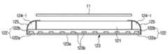
도 1은 본 발명의 제 1 실시예에 따른 디스플레이 장치의 사시도이다.
도 2는 본 발명의 제 1 실시예에 따른 디스플레이 장치에 적용된 디스플레이 모듈의 분해 사시도이다.
도 3은 본 발명의 제 1 실시예에 따른 디스플레이 장치에 적용된 디스플레이 모듈의 단면도이다.
도 4는 본 발명의 제 1 실시예에 따른 디스플레이 장치에 적용된 백라이트의 정면도이다.
도 5는 본 발명의 제 1 실시예에 따른 디스플레이 장치에 적용된 광원 및 확산부재의 설치 상태를 보인 단면도이다.
도 6은 본 발명의 제 2 실시예에 따른 삼차원 디스플레이 장치에 적용된 디스플레이 모듈의 단면도이다.
도 7은 본 발명의 제 3 실시예에 따른 삼차원 디스플레이 장치에 적용된 디스플레이 모듈의 단면도이다.1 is a perspective view of a display device according to a first embodiment of the present invention.
2 is an exploded perspective view of a display module applied to a display device according to a first embodiment of the present invention.
3 is a cross-sectional view of a display module applied to a display device according to a first embodiment of the present invention.
4 is a front view of a backlight applied to a display device according to the first embodiment of the present invention.
5 is a cross-sectional view illustrating a mounting state of a light source and a diffusion member applied to the display device according to the first embodiment of the present invention.
6 is a cross-sectional view of a display module applied to a three-dimensional display device according to a second embodiment of the present invention.
7 is a cross-sectional view of a display module applied to a three-dimensional display device according to a third embodiment of the present invention.
이하에서는 본 발명의 일 실시예에 따른 디스플레이 장치를 도면을 참조하여 상세히 설명한다.Hereinafter, a display device according to an embodiment of the present invention will be described in detail with reference to the drawings.
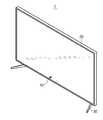
도 1에 도시한 바와 같이 본 발명의 일 실시예에 따른 디스플레이 장치(1)는 영상 표시를 위한 디스플레이 모듈(10)과, 디스플레이 모듈(10)을 수용하며 디스플레이 장치(1)의 외관을 형성하는 케이스(20)를 포함하며, 케이스(20)의 후면에는 디스플레이 장치(1)가 수평면에 서 있는 상태로 설치될 수 있도록 하는 스탠드(30)가 연결된다.1, a
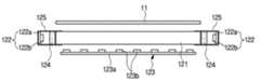
디스플레이 모듈(10)은 도 2 및 도 3에 도시한 바와 같이 영상이 표시되는 디스플레이 패널(11)과, 광을 발생시켜 디스플레이 패널(11)에 공급하는 백라이트(2)를 포함한다.The
디스플레이 패널(11)은 사각 평판 형상으로 형성된 액정 패널로 이루어진다.The
백라이트(12)는 광을 디스플레이 패널(11)로 안내하는 도광판(121)과, 광을 발생시키는 광원(122, 123)들을 포함한다.The
도광판(121)은 투명 재질로 형성되되 디스플레이 패널(11)과 대응하도록 사각 평판 형상으로 형성되어 디스플레이 패널(11)의 후방측에 배치된다. 도면으로 도시되지는 않았으나 도광판(121)에는 광이 부위에 따라 선택적으로 도광판(121)에서 디스플레이 패널(11)로 출사될 수 있도록 하는 패턴이 마련되어, 패턴에 의해 패럴럭스 배리어의 역할이 수행되도록 되어 있다.The
광원(122, 123)들에는 디스플레이 장치(1)가 삼차원 영상을 표시할 경우에 사용되는 삼차원 광원(122)과, 디스플레이 장치(1)가 이차원 영상을 표시할 경우에 사용되는 이차원 광원(123)가 포함된다.The
삼차원 광원(122) 및 이차원 광원(123)은 각각 기판(122a, 123a)과, 기판(122a, 123a)에 배치된 복수의 발광 다이오드(122b, 123b)들을 포함한다. 삼차원 광원(122)의 기판(122a)은 도광판(121)의 측단과 평행하게 배치되며, 삼차원 광원(122)의 발광 다이오드(122b)들은 도광판(121)의 측단과 대향되게 배치되어 도광판(121)의 측단을 향해 광을 조사한다. 발광 다이오드(122b)들은 도 4에 도시한 바와 같이 기판(122a)의 길이 방향으로 서로 이격 배치된다. 본 실시예에서는 두 개의 삼차원 광원(122)이 도광판(121)의 양측에 배치되어 도광판(121)의 양측단을 통해 도광판(121) 내로 광이 입사된다.The three-
이차원 광원(123)의 기판(123a)은 사각 평판 형상으로 형성되어 도광판(121)의 후방측에 도광판(121)과 평행하게 배치되며, 이차원 광원(123)의 발광 다이오드(123b)들은 기판(123a)의 전면에 도광판(121)의 후면과 대향되게 배치되어 도광판(121)의 후면을 향해 광을 조사한다.The two-
따라서 삼차원 광원(122)들에서 발생한 광은 도광판(121)의 양 측단을 통해 도광판(121) 내로 입사되었다가 전방의 디스플레이 패널(11)을 향해 출사되고, 이차원 광원(123)에서 발생한 광은 도광판(121)의 후면을 통해 입사되었다가 도광판(121)을 그대로 통과하여 전방의 디스플레이 패널(11)을 향해 출사된다.The light generated by the three-
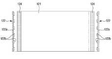
상술한 바와 같이 삼차원 광원(122)은 도 4에 도시한 바와 같이 복수의 발광 다이오드(122b)들이 기판(122a)의 길이 방향으로 서로 이격 배치되는데, 이와 같이 구성할 경우 도광판(121)에 있어서 삼차원 광원(122)의 발광다이오드(122b)들과 인접한 부위에는 상대적으로 많은 양의 광이 전달되는 반면 삼차원 광원(122) 발광 다이오드(122b)들로부 먼 부위에는 상대적으로 적은 양의 광이 공급될 수 밖에 없으며, 그에 따라 도광판(121)의 측단에는 상대적으로 밝은 명부와 상대적으로 어두운 암부가 발생할 수 있다.As described above, the three-
따라서 이와 같은 도광판(121)에서의 명부 및 암부의 발생을 억제하기 위해 백라이트(12)는 두 삼차원 광원(122)과 도광판(121) 양 측단사이에 배치되는 확산부재(124)를 포함한다.Therefore, the
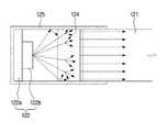
확산부재(124)는 광을 확산시켜 삼차원 광원(122)에 전달한다. 본 실시예에서 확산부재(124)는 백색 반투명 재질로 형성되어 광을 확산시킬 수 있도록 되어 있다. 이러한 확산부재(124)는 사각 바 형상으로 형성되며 두 개가 구비되어 도광판(121)의 양 측단 측방에 나란히 배치된다. 확산부재(124)의 일측에 마련된 제 1 면은 삼차원 광원(122)과 대향되도록 배치되고, 제 1 면과 반대측에 위치한 확산부재(124)의 제 2 면이 도광판(121)의 측단과 대향되도록 배치된다. 본 실시예에서 삼차원 광원(122)의 기판(122a)은 확산부재(124)의 제 1 면과 평행하게 이격 배치되며, 삼차원 광원(122)의 발광 다이오드(122b) 또한 확산부재(124)의 제 1 면과 이격 배치된다.The
따라서 삼차원 광원(122)에서 발생한 광은 도 5에 도시한 바와 같이 확산부재(124)의 제 1 면을 통해 확산부재(124) 내로 입사되어 확산부재(124)를 통과하는 과정에서 확산되고, 확산된 광은 확산부재(124)의 제 2 면을 통해 출사되어 도광판(121)의 측단으로 입사된다. 이때, 발광 다이오드(122b)들에서 발생한 광들은 확산부재(124)를 통과하는 과정에서 확산되므로, 확산부재(124)의 제 2 면에서 출사되는 광은 전체적으로 고른 광량 분포를 가지게 된다. 따라서 도광판(121)의 측단에는 전체적으로 고른 광량 분포를 갖는 광이 입사되므로, 삼차원 광원(122)과 인접한 도광판(121)의 양 측단에서 암부 및 명부가 발생하는 것은 방지된다.5, the light generated by the three-
또한 백라이트(12)는 삼차원 광원(122)에서 발생한 광이 누설되는 것을 방지하기 위한 반사 시트(125)를 포함한다. 반사 시트(125)는 삼차원 광원(122)과 확산부재(124) 사이에 형성되는 공간 외측을 덮도록 마련되어, 삼차원 광원(122)에서 발생한 광이 모두 확산부재(124)로 입사될 수 있도록 한다. 본 실시예에서 반사 시트(125)는 두 개의 삼차원 광원(122) 및 두 개의 확산부재(124)에 대응하도록 두 개가 구비된다. 반사 시트(125)는 U자 형상으로 형성되어 내측에 삼차원 광원(122) 및 확산부재(124)를 수용한다. 또한 반사 시트(125)의 양 끝단은 도광판(121)의 측단 일부를 덮도록 연장된다.In addition, the
본 실시예에서 확산부재(124)는 사각형 단면을 갖는 사각 바 형상으로 형성되어 삼차원 광원(122)과 대향된 제 1 면과 도광판(121) 측단과 대향된 제 2 면이 서로 반대측에 위치하고 있으나, 이에 한정되는 것은 아니며, 도 6에 도시한 바와 같이 삼차원 광원(122)의 기판(122a)이 이차원 광원(123)의 기판(123a)의 측방에 나란히 배치하여, 도광판(121)의 제 1 면과 제 2 면이 서로 직각인 위치에 위치하도록 하는 것도 가능하다. 이러한 경우에는 확산부재(124)의 단면 형상을 사각형 대신 사분원 형상으로 형성하는 것도 가능하다.In this embodiment, the
본 실시예에서 백라이트(12)는 삼차원 광원(122) 및 이차원 광원(123)을 포함하여, 디스플레이 장치(1)가 이차원 및 삼차원 화면을 표현할 수 있도록 되어 있으나, 이에 한정되는 것은 아니며, 상기 실시예에서 이차원 광원(123)에 대응하는 구성 없이 도 7에 도시한 바와 같이 도광판(121)의 양 측단과 대향하는 한 쌍의 광원(122)만을 포함하여 삼차원 영상과 이차원 영상 중 어느 하나만을 표시할 수 있는 디스플레이 장치에도 본 발명에 따른 확산부재(124) 및 반사 시트(125)가 그대로 적용될 수 있다.The
본 실시예에서 삼차원 광원(122)은 기판(122a) 및 발광 다이오드(122b)들을 포함하여, 확산부재(124)가 발광 다이오드(122b)들에서 발생한 광을 확산시키도록 되어 있으나, 이에 한정되는 것은 아니며, 발광 다이오드(122b) 외에 다른 종류의 광원이 사용될 경우에도 도광판(121)의 측단에 전달되는 광의 광량 분포를 균일하게 하기 위해 본 발명의 확산부재(124)가 사용될 수 있다.The three dimensional
또한 본 실시예에서 반사 시트(125)의 양 끝단은 도광판(121)의 측단 일부를 덮도록 연장되는데, 일반적으로 이러한 구조는 도광판(121)의 측단 일부에서 발생할 수 있는 암부 및 명부를 가리기 위한 것이다.In this embodiment, both ends of the
본 발명과 같이 확산부재(124)를 포함한 백라이트(12)의 경우, 도광판(121) 측단에서의 암부 및 명부 발생을 억제할 수 있으므로 반사 시트(125)가 도광판(121)의 측단을 덮지 않도록 구성하는 것도 가능하다. 또한 이와 같이 구성할 경우 도광판(121)의 전면 전체를 통해 광이 출사될 수 있으므로, 화면이 표시되는 디스플레이 패널(11)의 표시 영역의 면적과 도광판(121)의 면적을 실질적으로 동일하게 구성할 수 있다.The
또한 본 실시예에서 백라이트(12)는 도광판(121)의 양 측단과 대응하도록 삼차원 광원(122) 및 확산부재(124)를 각각 한 쌍씩 포함하나, 이에 한정되는 것은 아니며, 백라이트(12)가 도광판(121)의 일측단에 대응하는 하나의 삼차원 광원(122) 및 하나의 확산부재(124)를 포함하도록 하되, 도광판(121)의 타측단에 배치되어 광을 반사하는 반사부재(미도시)를 포함하도록 하는 것도 가능하다.The
본 실시예에서 광은 도광판(121)에 마련된 패턴에 의해 선택적으로 도광판(121)에서 디스플레이 패널(11)로 출사되나, 이에 한정되는 것은 아니며, 패턴에 대응하는 구성 없이 디스플레이 패널(11)과 도광판(121) 사이에 패럴럭스 배리어나 렌티큘러 렌즈를 배치하는 것도 가능하다.In this embodiment, the light is selectively emitted from the
본 발명은 상기에서 기재된 실시예들에 한정되는 것이 아니며, 본 발명의 사상 및 범위를 벗어나지 않고 다양하게 수정 및 변형할 수 있음은 이 기술의 분야에서 통상의 지식을 가진 자에게 자명하다. 따라서, 그러한 수정예 또는 변형예들은 본 발명의 특허청구범위에 속한다 하여야 할 것이다.It will be apparent to those skilled in the art that various modifications and variations can be made in the present invention without departing from the spirit and scope of the invention. Accordingly, such modifications or variations are intended to fall within the scope of the appended claims.
1: 디스플레이 장치 10: 디스플레이 모듈
11: 디스플레이 패널 12: 백라이트
121: 도광판 122: 삼차원 광원
123: 이차원 광원 124: 확산부재
125: 반사 시트 20: 케이스
30: 스탠드1: display device 10: display module
11: Display panel 12: Backlight
121: light guide plate 122: three-dimensional light source
123: two-dimensional light source 124: diffusion member
125: reflective sheet 20: case
30: Stand
Claims (14)
Translated fromKorean상기 디스플레이 패널로 광을 공급하는 백라이트를 포함하며,
상기 백라이트는 광을 상기 디스플레이 패널로 안내하는 도광판과,
상기 도광판의 측단에 대향되게 배치되는 적어도 하나의 삼차원 광원과,
상기 도광판의 후방측에 배치되는 이차원 광원과,
상기 적어도 하나의 삼차원 광원과 상기 도광판의 측단 사이에 배치되는 적어도 하나의 확산부재를 포함하는 디스플레이 장치.A display panel,
And a backlight for supplying light to the display panel,
The backlight includes a light guide plate for guiding light to the display panel,
At least one three-dimensional light source disposed opposite to a side end of the light guide plate,
A two-dimensional light source disposed on a rear side of the light guide plate,
And at least one diffusion member disposed between the at least one three-dimensional light source and a side end of the light guide plate.
상기 확산부재는 상기 삼차원 광원과 대향되는 제 1 면과, 상기 도광판의 측단과 대향되는 제 2 면을 포함하는 디스플레이 장치.The method according to claim 1,
Wherein the diffusion member includes a first surface facing the three-dimensional light source, and a second surface opposed to the side surface of the light guide plate.
상기 확산부재는 사각 바 형상으로 형성되며 상기 제 1 면과 상기 제 2 면은 서로 반대측에 위치하는 디스플레이 장치.3. The method of claim 2,
Wherein the diffusion member is formed in a square bar shape, and the first surface and the second surface are located on opposite sides.
상기 제 1 면과 상기 제 2 면은 서로 직각인 위치에 위치하는 디스플레이 장치.3. The method of claim 2,
Wherein the first surface and the second surface are positioned at right angles to each other.
상기 삼차원 광원은 상기 제 2 면과 평행하게 배치되는 기판과, 상기 기판에 상기 제 2 면과 대향되게 배치되는 복수의 발광 다이오드들을 포함하는 디스플레이 장치.The method of claim 3,
Wherein the three-dimensional light source includes a substrate disposed in parallel with the second surface, and a plurality of light emitting diodes disposed on the substrate so as to face the second surface.
상기 확산부재는 백색 반투명 재질로 형성되는 디스플레이 장치.3. The method of claim 2,
Wherein the diffusion member is formed of a white translucent material.
상기 백라이트는 상기 적어도 하나의 삼차원 광원과 상기 적어도 하나의 확산부재 사이의 공간 외측을 덮도록 마련되는 적어도 하나의 반사 시트를 포함하는 디스플레이 장치.The method according to claim 1,
Wherein the backlight comprises at least one reflective sheet provided to cover an outer space of the space between the at least one three-dimensional light source and the at least one diffusion member.
상기 반사 시트는 U자 형상으로 형성되어 내측에 상기 삼차원 광원과 상기 확산부재를 수용하는 디스플레이 장치.8. The method of claim 7,
Wherein the reflective sheet is formed in a U-shape and accommodates the three-dimensional light source and the diffusion member inside.
상기 반사 시트의 양 끝단은 상기 도광판의 측단 일부를 덮도록 연장되는 디스플레이 장치.9. The method of claim 8,
And both ends of the reflective sheet extend to cover a part of a side edge of the light guide plate.
상기 적어도 하나의 삼차원 광원은 상기 도광판의 양 측단에 각각 대응하는 한 쌍의 삼차원 광원을 포함하며,
상기 적어도 하나의 확산부재는 상기 도광판의 양 측단과 상기 한 쌍의 삼차원 광원 사이에 배치되는 한 쌍의 확산부재를 포함하는 디스플레이 장치.The method according to claim 1,
Wherein the at least one three-dimensional light source includes a pair of three-dimensional light sources respectively corresponding to both ends of the light guide plate,
Wherein the at least one diffusion member includes a pair of diffusion members disposed between both ends of the light guide plate and the pair of three-dimensional light sources.
상기 디스플레이 패널의 후방측에 배치되어 상기 디스플레이 패널에 광을 공급하는 백라이트를 포함하며,
상기 백라이트는 판 형상으로 형성되어 상기 디스플레이 패널의 후방에 배치되는 도광판과, 상기 도광판의 양 측방에 배치되는 한 쌍의 광원과, 상기 한 쌍의 광원에서 공급된 광을 확산시켜 상기 도광판에 전달하는 한 쌍의 확산부재를 포함하는 디스플레이 장치.A display panel,
And a backlight disposed on a rear side of the display panel to supply light to the display panel,
The backlight includes a light guide plate formed in a plate shape and disposed behind the display panel, a pair of light sources disposed on both sides of the light guide plate, and a light source for diffusing the light supplied from the pair of light sources and transmitting the light to the light guide plate A display device comprising a pair of diffusion members.
상기 확산부재는 사각 바 형상으로 형성되어 그 일측에 마련된 제 1 면이 상기 광원과 대향되고 상기 제 1 면에 대해 반대측에 위치한 제 2 면이 상기 도광판의 측단과 대향되는 디스플레이 장치.12. The method of claim 11,
Wherein the diffusion member is formed in a square bar shape and has a first surface opposed to the light source and a second surface opposed to the first surface opposed to a side surface of the light guide plate.
상기 광원은 상기 제 2 면과 평행하게 배치되는 기판과, 상기 기판에 상기 제 2 면과 대향되게 배치되는 복수의 발광 다이오드들을 포함하는 디스플레이 장치.13. The method of claim 12,
Wherein the light source includes a substrate disposed in parallel with the second surface, and a plurality of light emitting diodes disposed on the substrate so as to face the second surface.
상기 백라이트는 U자 형상으로 형성되어 내측에 상기 삼차원 광원과 상기 확산부재를 수용하는 한 쌍의 반사 시트를 포함하는 디스플레이 장치.13. The method of claim 12,
Wherein the backlight comprises a pair of reflective sheets formed in a U-shape and accommodating the three-dimensional light source and the diffusion member inwardly.
Priority Applications (4)
| Application Number | Priority Date | Filing Date | Title |
|---|---|---|---|
| KR1020140172858AKR20160067447A (en) | 2014-12-04 | 2014-12-04 | Display apparatus |
| EP15181288.0AEP3029517B1 (en) | 2014-12-04 | 2015-08-17 | Display apparatus comprising a backlight |
| US14/834,525US20160161659A1 (en) | 2014-12-04 | 2015-08-25 | Display apparatus |
| CN201510828817.2ACN105676338A (en) | 2014-12-04 | 2015-11-25 | Display apparatus |
Applications Claiming Priority (1)
| Application Number | Priority Date | Filing Date | Title |
|---|---|---|---|
| KR1020140172858AKR20160067447A (en) | 2014-12-04 | 2014-12-04 | Display apparatus |
Publications (1)
| Publication Number | Publication Date |
|---|---|
| KR20160067447Atrue KR20160067447A (en) | 2016-06-14 |
Family
ID=53938149
Family Applications (1)
| Application Number | Title | Priority Date | Filing Date |
|---|---|---|---|
| KR1020140172858AWithdrawnKR20160067447A (en) | 2014-12-04 | 2014-12-04 | Display apparatus |
Country Status (4)
| Country | Link |
|---|---|
| US (1) | US20160161659A1 (en) |
| EP (1) | EP3029517B1 (en) |
| KR (1) | KR20160067447A (en) |
| CN (1) | CN105676338A (en) |
Cited By (3)
| Publication number | Priority date | Publication date | Assignee | Title |
|---|---|---|---|---|
| CN109696772A (en)* | 2017-10-23 | 2019-04-30 | 三星电子株式会社 | Display device with diffuser plate supporting member |
| WO2020060326A1 (en)* | 2018-09-21 | 2020-03-26 | Samsung Electronics Co., Ltd. | Display apparatus |
| KR20220146346A (en)* | 2021-04-23 | 2022-11-01 | 애플 인크. | Narrow border display |
Families Citing this family (11)
| Publication number | Priority date | Publication date | Assignee | Title |
|---|---|---|---|---|
| US10386571B1 (en)* | 2015-02-26 | 2019-08-20 | Cooper Technologies Company | Apparatus for coupling light into lightguides |
| CN105446058B (en)* | 2016-01-07 | 2019-03-22 | 林璧光 | A kind of straight illuminated and the disposable LED illumination lamp for shooting of sheen formula |
| USD810348S1 (en) | 2016-02-26 | 2018-02-13 | Cooper Technologies Company | Dual lightguide light fixture |
| CN109477625A (en)* | 2016-07-26 | 2019-03-15 | 镭亚股份有限公司 | Bar shaped collimator, backlight body system and method |
| CN208074604U (en)* | 2017-03-10 | 2018-11-09 | 晨丰光电股份有限公司 | Wavelength conversion light guide component and light source module |
| KR102617358B1 (en) | 2018-08-13 | 2023-12-21 | 레이아 인코포레이티드 | Grating collimator, backlight system light method using optical recirculating light source |
| DE202020101944U1 (en)* | 2019-09-30 | 2021-01-15 | Covestro Deutschland Ag | LED lighting elements based on multi-layer bodies with a stone look |
| CN111531283A (en)* | 2020-06-09 | 2020-08-14 | 陈杰勇 | Efficient processing technology of light guide component |
| CN113050327A (en)* | 2021-03-10 | 2021-06-29 | 武汉天马微电子有限公司 | Backlight module and display device |
| WO2023218874A1 (en)* | 2022-05-09 | 2023-11-16 | ソニーグループ株式会社 | Display device, display control method, and display control program |
| CN115616816A (en)* | 2022-10-13 | 2023-01-17 | 合肥京东方视讯科技有限公司 | Backlight module and liquid crystal display device |
Family Cites Families (14)
| Publication number | Priority date | Publication date | Assignee | Title |
|---|---|---|---|---|
| US6007209A (en)* | 1997-03-19 | 1999-12-28 | Teledyne Industries, Inc. | Light source for backlighting |
| KR100699266B1 (en)* | 2005-09-09 | 2007-03-27 | 삼성전자주식회사 | Backlight unit and display device including same |
| JP2007141735A (en)* | 2005-11-21 | 2007-06-07 | Planet Company:Kk | Double-sided light emitting panel |
| DE102006056150A1 (en)* | 2006-11-28 | 2008-05-29 | Patent-Treuhand-Gesellschaft für elektrische Glühlampen mbH | Electromagnetic rays radiating device for use in display device, has radiation uncoupling surface arranged in ray path of radiation-emitting arrangement, and radiation-steering unit directing electromagnetic ray to uncoupling surface |
| JP2008153057A (en)* | 2006-12-18 | 2008-07-03 | Citizen Electronics Co Ltd | Light source unit, backlight unit, and display device |
| TW200909931A (en)* | 2007-08-22 | 2009-03-01 | Nano Prec Corp | Backlight module and liquid crystal display using the same |
| KR101555340B1 (en)* | 2008-11-05 | 2015-09-30 | 삼성디스플레이 주식회사 | Backlight assembly and liquid crystal display device having the same |
| WO2012098739A1 (en)* | 2011-01-21 | 2012-07-26 | 三菱電機株式会社 | Surface light source device and liquid crystal display device |
| KR20120105810A (en)* | 2011-03-16 | 2012-09-26 | 삼성디스플레이 주식회사 | Backlight assembly and display device having the same |
| CN202253209U (en)* | 2011-10-14 | 2012-05-30 | 深圳市华星光电技术有限公司 | Backlight module and liquid crystal display comprising same |
| CN202546445U (en)* | 2012-03-09 | 2012-11-21 | 京东方科技集团股份有限公司 | Light mixing strip, line light source assembly, backlight source and liquid crystal display device |
| US9328897B2 (en)* | 2012-08-08 | 2016-05-03 | Shenzhen China Star Optoelectronics Technology Co., Ltd. | Edge-illumination type backlight module and liquid crystal display using the same |
| TWI504988B (en)* | 2012-11-28 | 2015-10-21 | Innocom Tech Shenzhen Co Ltd | Backlight module and liquid crystal display device |
| CN104749818A (en)* | 2013-12-26 | 2015-07-01 | 富泰华精密电子(郑州)有限公司 | Sidelight backlight module and LGP (Light Guide Plate) thereof |
- 2014
- 2014-12-04KRKR1020140172858Apatent/KR20160067447A/ennot_activeWithdrawn
- 2015
- 2015-08-17EPEP15181288.0Apatent/EP3029517B1/ennot_activeNot-in-force
- 2015-08-25USUS14/834,525patent/US20160161659A1/ennot_activeAbandoned
- 2015-11-25CNCN201510828817.2Apatent/CN105676338A/ennot_activeWithdrawn
Cited By (9)
| Publication number | Priority date | Publication date | Assignee | Title |
|---|---|---|---|---|
| CN109696772A (en)* | 2017-10-23 | 2019-04-30 | 三星电子株式会社 | Display device with diffuser plate supporting member |
| CN109696772B (en)* | 2017-10-23 | 2023-02-21 | 三星电子株式会社 | Display device with diffusion plate supporting member |
| WO2020060326A1 (en)* | 2018-09-21 | 2020-03-26 | Samsung Electronics Co., Ltd. | Display apparatus |
| KR20200034247A (en)* | 2018-09-21 | 2020-03-31 | 삼성전자주식회사 | Display apparatus |
| US10928675B2 (en) | 2018-09-21 | 2021-02-23 | Samsung Electronics Co., Ltd. | Display apparatus |
| KR20220146346A (en)* | 2021-04-23 | 2022-11-01 | 애플 인크. | Narrow border display |
| US11906775B2 (en) | 2021-04-23 | 2024-02-20 | Apple Inc. | Narrow border display |
| KR20240031259A (en)* | 2021-04-23 | 2024-03-07 | 애플 인크. | Narrow border display |
| US12147071B1 (en) | 2021-04-23 | 2024-11-19 | Apple Inc. | Narrow border display |
Also Published As
| Publication number | Publication date |
|---|---|
| EP3029517A1 (en) | 2016-06-08 |
| CN105676338A (en) | 2016-06-15 |
| EP3029517B1 (en) | 2017-12-13 |
| US20160161659A1 (en) | 2016-06-09 |
Similar Documents
| Publication | Publication Date | Title |
|---|---|---|
| KR20160067447A (en) | Display apparatus | |
| KR101326299B1 (en) | Display module and displyay apparatus having the same | |
| KR102034890B1 (en) | Display apparatus | |
| KR101706101B1 (en) | Display apparatus | |
| US20140140094A1 (en) | Light source device, display unit, and electronic apparatus | |
| KR102171307B1 (en) | Three dimensional display apparatus and manufacturing method for the same | |
| US20120306861A1 (en) | Light source device and display | |
| KR102373178B1 (en) | Display apparatus | |
| EP2887661A1 (en) | Apparatus for displaying a three-dimensional image | |
| US20170205658A1 (en) | Display apparatus | |
| JP2014013690A (en) | Display device | |
| JP6495179B2 (en) | Backlight device and display device | |
| JP2013073876A (en) | Liquid crystal display device | |
| WO2015037404A1 (en) | Display device | |
| JP2012252937A (en) | Light source device and display device | |
| US20170031087A1 (en) | Display apparatus | |
| JP2014022208A (en) | Display device | |
| KR102493918B1 (en) | Display apparatus | |
| US10321120B2 (en) | Display apparatus with electrochromic mirror | |
| TWM500266U (en) | Display module | |
| KR20130134559A (en) | Display module and display apparatus having the same | |
| JPWO2017037855A1 (en) | Display device | |
| KR20150105870A (en) | Display apparatus | |
| US9958600B2 (en) | Light-source device and display apparatus | |
| KR20170015037A (en) | Show case |
Legal Events
| Date | Code | Title | Description |
|---|---|---|---|
| PA0109 | Patent application | Patent event code:PA01091R01D Comment text:Patent Application Patent event date:20141204 | |
| PG1501 | Laying open of application | ||
| PC1203 | Withdrawal of no request for examination | ||
| WITN | Application deemed withdrawn, e.g. because no request for examination was filed or no examination fee was paid |