KR20160061825A - Fuse/relay unit - Google Patents
Fuse/relay unitDownload PDFInfo
- Publication number
- KR20160061825A KR20160061825AKR1020140164748AKR20140164748AKR20160061825AKR 20160061825 AKR20160061825 AKR 20160061825AKR 1020140164748 AKR1020140164748 AKR 1020140164748AKR 20140164748 AKR20140164748 AKR 20140164748AKR 20160061825 AKR20160061825 AKR 20160061825A
- Authority
- KR
- South Korea
- Prior art keywords
- fuse
- relay
- mounting portion
- terminal
- housing
- Prior art date
- Legal status (The legal status is an assumption and is not a legal conclusion. Google has not performed a legal analysis and makes no representation as to the accuracy of the status listed.)
- Withdrawn
Links
- 238000009434installationMethods0.000claimsabstractdescription17
- 238000003780insertionMethods0.000claimsdescription12
- 230000037431insertionEffects0.000claimsdescription12
- 239000000470constituentSubstances0.000description5
- 238000010586diagramMethods0.000description2
- 238000002347injectionMethods0.000description2
- 239000007924injectionSubstances0.000description2
- 230000000694effectsEffects0.000description1
- 239000011810insulating materialSubstances0.000description1
- 238000012423maintenanceMethods0.000description1
- 238000012986modificationMethods0.000description1
- 230000004048modificationEffects0.000description1
- 239000004065semiconductorSubstances0.000description1
Images


Classifications
- H—ELECTRICITY
- H01—ELECTRIC ELEMENTS
- H01R—ELECTRICALLY-CONDUCTIVE CONNECTIONS; STRUCTURAL ASSOCIATIONS OF A PLURALITY OF MUTUALLY-INSULATED ELECTRICAL CONNECTING ELEMENTS; COUPLING DEVICES; CURRENT COLLECTORS
- H01R13/00—Details of coupling devices of the kinds covered by groups H01R12/70 or H01R24/00 - H01R33/00
- H01R13/66—Structural association with built-in electrical component
- H01R13/68—Structural association with built-in electrical component with built-in fuse
- H01R13/684—Structural association with built-in electrical component with built-in fuse the fuse being removable
- H01R13/688—Structural association with built-in electrical component with built-in fuse the fuse being removable with housing part adapted for accessing the fuse
- H—ELECTRICITY
- H01—ELECTRIC ELEMENTS
- H01R—ELECTRICALLY-CONDUCTIVE CONNECTIONS; STRUCTURAL ASSOCIATIONS OF A PLURALITY OF MUTUALLY-INSULATED ELECTRICAL CONNECTING ELEMENTS; COUPLING DEVICES; CURRENT COLLECTORS
- H01R2201/00—Connectors or connections adapted for particular applications
- H01R2201/26—Connectors or connections adapted for particular applications for vehicles
Landscapes
- Fuses (AREA)
Abstract
Translated fromKoreanDescription
Translated fromKorean본 발명은 퓨즈/릴레이 유니트에 관한 것으로, 더욱 상세하게는 퓨즈와 릴레이를 동시에 내장하고 유니트 내부에서 퓨즈와 릴레이를 전기적으로 연결하여 사용할 수 있는 퓨즈/릴레이 유니트에 관한 것이다.
BACKGROUND OF THE
예를 들어 차량에서 사용되는 차량용 블럭에는 다수개의 퓨즈와 릴레이가 설치되어 있고, 이들 퓨즈와 릴레이는 서로 짝을 이뤄 특정한 전장부품이나 장치에 과부하가 걸리는 것을 방지하게 된다. 이와 같이 하나의 전장부품이나 전자장치에 대해서 상기 퓨즈와 릴레이는 반드시 쌍을 이뤄 사용되는 경우가 많다.For example, a vehicle block used in a vehicle is provided with a plurality of fuses and relays, and these fuses and relays are paired with each other to prevent overloading of certain electrical components or devices. As described above, in many cases, the fuse and the relay are always used in pairs for one electric component or an electronic device.
도 1에는 차량용 블럭에서 퓨즈와 릴레이가 쌍을 이뤄서 사용되는 것을 보인 회로도가 도시되어 있다. 이에 따르면, 전원(1)에서 전장부품의 예인 에어콘(7)으로 전원이 공급됨에 있어서 퓨즈(3)와 릴레이(5)가 회로상에 구비된다. 이때, 상기 퓨즈(3)와 릴레이(5)는 예를 들면 차량용 블럭 등에 장착되는데, 상기 퓨즈(3)와 전원(1), 상기 퓨즈(3)와 릴레이(5), 상기 릴레이(5)와 부하인 에어콘(7)이 서로 전기적으로 연결되도록 하기 위해서는 많은 단자와 전선이 필요하게 된다.1 is a circuit diagram showing that a fuse and a relay are used in a pair in a vehicle block. According to this, the
즉, 퓨즈(3)를 차량용 블럭에 설치하기 위해 단자연결부(9)가 2곳에서 필요하고, 상기 릴레이(5)를 차량용 블럭에 설치하기 위해서는 4곳에서 단자연결부(9)가 필요하게 된다. 따라서, 상기 퓨즈(3)와 릴레이(5)가 사용되기 위해서는 많은 단자와 와이어 등이 구비되어야 하므로 차량용 블럭의 크기가 커지는 등의 문제점이 있다.
That is, two
본 발명의 목적은 상기한 바와 같은 종래의 문제점을 해결하기 위한 것으로, 퓨즈와 릴레이를 교체가능하게 장착하도록 함과 동시에 자체적으로 퓨즈와 릴레이가 직접 전기적으로 연결되도록 하는 것이다.SUMMARY OF THE INVENTION An object of the present invention is to solve the above-mentioned problems of the prior art, and it is an object of the present invention to replace a fuse and a relay so that the fuse and a relay are directly electrically connected to each other.
본 발명의 다른 목적은 퓨즈와 릴레이를 동시에 회로에 연결할 수 있도록 하는 것이다.
Another object of the present invention is to enable the fuse and the relay to be connected to the circuit at the same time.
상기한 바와 같은 목적을 달성하기 위한 본 발명의 특징에 따르면, 본 발명은 퓨즈장착부와 릴레이장착부가 형성되고 상기 퓨즈장착부와 릴레이장착부로 개방되는 단자삽입공간이 구비되는 하우징과, 상기 퓨즈장착부로 개방되는 단자삽입공간중 하나에 설치되어 전원 측과 상기 퓨즈장착부에 장착된 퓨즈를 전기적으로 연결하는 입력단자와, 상기 퓨즈장착부와 릴레이장착부로 각각 개방되는 단자삽입공간에 설치되어 상기 퓨즈와 릴레이를 전기적으로 연결하는 연결단자와, 상기 릴레이장착부로 개방되는 단자삽입공간에 설치되어 부하 측과 상기 릴레이장착부에 장착된 릴레이를 전기적으로 연결하는 출력단자를 포함한다.According to an aspect of the present invention for achieving the above object, the present invention provides a semiconductor device comprising: a housing having a fuse mounting portion and a relay mounting portion formed therein and having a terminal insertion space opened to the fuse mounting portion and the relay mounting portion; An input terminal provided in one of the terminal insertion spaces and electrically connected to the fuse mounted on the power supply side and the fuse mounting portion, and a terminal insertion space opened to the fuse mounting portion and the relay mounting portion to electrically connect the fuse and the relay And an output terminal provided in the terminal insertion space opened to the relay mounting portion and electrically connecting the load side and the relay mounted on the relay mounting portion.
상기 하우징의 후단에는 유니트장착부의 안착공간에 안착되는 고정부가 형성되고 상기 고정부의 선단에는 상기 퓨즈장착부와 릴레이장착부가 형성된다.And a fixing part to be seated in a seating space of the unit mounting part is formed at the rear end of the housing, and the fuse mounting part and the relay mounting part are formed at the tip of the fixing part.
상기 고정부의 후단과 선단은 가상의 연장선이 소정의 각도를 가지고 만나도록 형성된다.The rear end and the tip end of the fixing portion are formed such that imaginary extension lines meet at a predetermined angle.
상기 입력단자에는 상기 퓨즈장착부로 개방된 단자설치공간에 위치되는 포크부와 상기 고정부의 외부로 돌출되는 탭부가 있고, 상기 출력단자에는 상기 릴레이장착부로 개방된 단자설치공간에 위치되는 포크부와 상기 고정부의 외부로 돌출되는 탭부가 있으며, 상기 포크부와 탭부는 가상의 연장선이 소정의 각도를 가지고 만나도록 형성된다.The input terminal includes a fork portion positioned in a terminal installation space opened to the fuse mounting portion and a tab portion protruding outward from the fixing portion. The output terminal includes a fork portion located in a terminal installation space opened by the relay mounting portion A tab portion protruding outward from the fixing portion, and the fork portion and the tab portion are formed such that imaginary extension lines meet at a predetermined angle.
상기 연결단자는 퓨즈와 릴레이의 일측 레그에 연결되는 2개의 연결포크부가 연결부에 의해 서로 연결되어 구성된다.
The connection terminal is configured such that two connection fork portions connected to a fuse and one leg of the relay are connected to each other by a connection portion.
본 발명에 의한 퓨즈/릴레이 유니트에서는 다음과 같은 효과를 얻을 수 있다.In the fuse / relay unit according to the present invention, the following effects can be obtained.
본 발명에서는 하우징의 릴레이장착부와 퓨즈장착부에 릴레이와 퓨즈를 장착할 수 있고, 이들이 연결단자에 의해 전기적으로 연결되고 상기 퓨즈와 연결되는 입력단자와 상기 릴레이와 연결되는 출력단자에 의해 회로와 연결되도록 하였다. 따라서, 전체 회로 구성에 있어서 퓨즈와 릴레이 사이의 연결이 연결단자에 의해서 완성되므로 회로가 간소하게 만들어지는 효과가 있다.In the present invention, the relay and the fuse can be mounted on the relay mounting portion and the fuse mounting portion of the housing, and they can be connected to the circuit by an input terminal electrically connected to the fuse and an output terminal connected to the relay, Respectively. Therefore, in the entire circuit configuration, the connection between the fuse and the relay is completed by the connection terminal, so that the circuit is simplified.
그리고, 본 발명에서는 하우징의 외부로 연장된 입력단자와 출력단자에 의해 차량용 블럭 등의 회로에 퓨즈와 릴레이를 동시에 연결할 수 있도록 하였고, 퓨즈장착부와 릴레이장착부에 릴레이와 퓨즈를 별도로 장착하고 분리할 수 있도록 하였으므로 퓨즈와 릴레이의 유지보수가 보다 간단하게 이루어지는 효과도 있다.
In the present invention, a fuse and a relay can be simultaneously connected to a circuit such as a vehicle block by an input terminal and an output terminal extended to the outside of the housing, and a relay and a fuse can be separately mounted and separated in the fuse mounting portion and the relay mounting portion. The maintenance of the fuse and the relay can be performed more simply.
도 1은 차량용 블럭에서 퓨즈와 릴레이가 쌍을 이뤄서 사용되는 것을 보인 회로도.
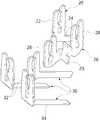
도 2는 본 발명에 의한 퓨즈/릴레이 유니트의 바람직한 실시례의 구성을 보인 사시도.
도 3은 본 발명 실시례를 구성하는 단자들을 보인 사시도.
도 4는 본 발명 실시례의 퓨즈/릴레이 유니트가 차량용 블럭에 장착되는 것을 보인 사용상태도.1 is a circuit diagram showing that a fuse and a relay are used in a pair in a vehicle block.
2 is a perspective view showing a configuration of a preferred embodiment of a fuse / relay unit according to the present invention.
3 is a perspective view showing terminals constituting an embodiment of the present invention.
4 is a state of use in which the fuse / relay unit of the embodiment of the present invention is shown mounted to a vehicle block;
이하, 본 발명의 일부 실시예들을 예시적인 도면을 통해 상세하게 설명한다. 각 도면의 구성요소들에 참조부호를 부가함에 있어서, 동일한 구성요소들에 대해서는 비록 다른 도면상에 표시되더라도 가능한 한 동일한 부호를 가지도록 하고 있음에 유의해야 한다. 또한, 본 발명의 실시예를 설명함에 있어, 관련된 공지구성 또는 기능에 대한 구체적인 설명이 본 발명의 실시예에 대한 이해를 방해한다고 판단되는 경우에는 그 상세한 설명은 생략한다.Hereinafter, some embodiments of the present invention will be described in detail with reference to exemplary drawings. It should be noted that, in adding reference numerals to the constituent elements of the drawings, the same constituent elements are denoted by the same reference numerals whenever possible, even if they are shown in different drawings. In the following description of the embodiments of the present invention, a detailed description of known functions and configurations incorporated herein will be omitted when it may make the difference that the embodiments of the present invention are not conclusive.
또한, 본 발명의 실시예의 구성 요소를 설명하는 데 있어서, 제 1, 제 2, A, B, (a), (b) 등의 용어를 사용할 수 있다. 이러한 용어는 그 구성 요소를 다른 구성 요소와 구별하기 위한 것일 뿐, 그 용어에 의해 해당 구성 요소의 본질이나 차례 또는 순서 등이 한정되지 않는다. 어떤 구성 요소가 다른 구성요소에 "연결", "결합" 또는 "접속"된다고 기재된 경우, 그 구성 요소는 그 다른 구성요소에 직접적으로 연결되거나 접속될 수 있지만, 각 구성 요소 사이에 또 다른 구성 요소가 "연결", "결합" 또는 "접속"될 수도 있다고 이해되어야 할 것이다.In describing the components of the embodiment of the present invention, terms such as first, second, A, B, (a), and (b) may be used. These terms are intended to distinguish the constituent elements from other constituent elements, and the terms do not limit the nature, order or order of the constituent elements. When a component is described as being "connected", "coupled", or "connected" to another component, the component may be directly connected or connected to the other component, Quot; may be "connected," "coupled," or "connected. &Quot;
도면들에 도시된 바에 따르면, 본 발명은 하우징(10)이 외관을 형성한다. 상기 하우징(10)은 절연성 재질로 만들어지는 것이다. 상기 하우징(10)에는 고정부(12)가 구비된다. 상기 고정부(12)는 아래에서 설명될 블럭몸체(40)의 안착공간(46)에 일부가 안착된다. 상기 고정부(12)는 도시된 실시례에서는 직선으로 연장되지 않고 후단과 선단이 소정의 각도를 이루도록 연장되어 있다. 하지만, 상기 고정부(12)가 전체적으로 직선으로 연장되게 형성될 수도 있다.As shown in the drawings, the present invention forms the appearance of the
상기 하우징(10)의 선단에는 퓨즈장착부(14)와 릴레이장착부(16)가 나란히 형성된다. 상기 퓨즈장착부(14)에는 도 4에 도시된 바와 같이 퓨즈(15)가 장착된다. 상기 퓨즈장착부(14)의 구성은 상기 퓨즈(15)의 일부가 내부에 안착될 수 있도록 내부가 상기 하우징(10)의 전방을 향해 개방되게 형성된다. 상기 릴레이장착부(16)에는 도 4에 도시된 바와 같이 릴레이(17)가 장착된다. 상기 릴레이장착부(16)도 상기 릴레이(17)의 일부가 장착될 수 있도록 하우징(10)의 전방을 향해 개방되게 형성된다. 상기 퓨즈장착부(14)와 릴레이장착부(16)는 상기 고정부(12)의 선단이 연장되는 방향으로 연장된다. 따라서, 도시된 실시례와 같이, 상기 고정부(12)의 선단이 후단에 대해 소정의 각도를 가지고 연장된다면 상기 퓨즈장착부(14)와 릴레이장착부(16)는 블럭몸체(40)의 표면에 대해 소정의 각도를 가지도록 경사진 방향을 향하게 된다. 이와 같은 구성은 작업자가 상기 퓨즈장착부(14)와 릴레이장착부(16)에 장착된 퓨즈(15)와 릴레이(17)를 보다 잘 볼 수 있도록 한다.A
상기 퓨즈장착부(14)와 릴레이장착부(16)의 내부로 개방되게 단자설치공간(18)이 형성된다. 상기 단자설치공간(18)은 상기 하우징(10)을 전후로 관통하게 형성된다. 물론, 아래에서 설명될 연결단자(26)가 위치되는 단자설치공간(18)은 반드시 그러해야 하는 것은 아니다. 즉, 연결단자(26)를 인서트사출하여 상기 하우징(10)을 만들게 되는 경우에는 상기 연결단자(26)가 설치되는 단자설치공간(18)은 하우징(10)의 전후로 관통하지 않아도 된다.A
상기 단자설치공간(18)들에는 도 3에 도시된 바와 같은 단자(20,26,30)들이 설치된다. 먼저, 입력단자(20)는 상기 퓨즈(15)의 일측 레그와 전기적으로 연결된다. 상기 입력단자(20)는 전원측과 연결된다. 상기 입력단자(20)에는 상기 퓨즈(15)의 일측과 연결되는 포크부(22)가 일단부에 있어 상기 단자설치공간(18) 내에 위치하고 타단부에는 탭부(24)가 있어 상기 하우징(10)의 고정부(12) 후방으로 연장된다. 상기 탭부(24)는 아래에서 설명될 블럭몸체(40)의 단자삽입부(48) 내부에 있는 단자(도시되지 않음)와 결합된다. 본 실시례에서는 상기 포크부(22)와 탭부(24)는 그 가상의 연장선이 소정의 각도를 가지도록 연결된다.
상기 단자설치공간(18)중 하나에는 연결단자(26)가 설치된다. 상기 연결단자(26)가 설치되는 단자설치공간(18)은 상기 퓨즈장착부(14) 및 릴레이장착부(16)로 각각 개방되게 형성된다. 상기 연결단자(26)는 상기 퓨즈(15)와 릴레이(17)를 전기적으로 연결하는 역할을 한다. 상기 연결단자(26)는 도 3에서 볼 수 있는 바와 같이, 2개의 연결포크부(28)가 연결부(29)에 의해 연결되어 있다. 상기 2개의 연결포크부(28)는 퓨즈(15)의 레그중 하나 그리고 릴레이(17)의 레그중 하나와 전기적으로 결합되는 것이다. 상기 연결포크부(28)는 같은 방향으로 연장되어 있다. 상기 연결단자(26)의 연결포크부(28)중 하나는 상기 퓨즈장착부(14)의 내부로 개방된 단자설치공간(18)의 부분에 위치하고 나머지 하나의 연결포크부(28)는 릴레이장착부(16)의 내부로 개방된 단자설치공간(18)의 부분에 위치된다.One of the
상기 릴레이장착부(16)의 내부로 개방되게 형성된 단자설치공간(18)들에는 각각 출력단자(30)가 설치된다. 상기 출력단자(30)들은 선단에 포크부(32)가 있고 후단에 탭부(34)가 있다. 그리고, 상기 입력단자(20)와 유사하게 상기 포크부(32)와 탭부(34)는 그 가상의 연장선이 소정의 각도를 가지도록 만난다. 상기 출력단자(30)들은 포크부(32)는 상기 릴레이(17)의 레그들과 전기적으로 연결되는 것이다. 상기 출력단자(30)들의 탭부(34)는 아래에서 설명될 블럭몸체(40)의 대응되는 단자삽입부(48)들에 있는 단자(도시되지 않음)와 결합된다. 상기 출력단자(30)들은 모두가 부하측과 연결되는 것은 아니고, 회로를 구성하기 위해 부하측, 접지측 등과 전기적으로 연결되는 것이다. 하지만, 편의상 출력단자(30)들은 전기적 연결을 기준으로 볼 때 입력측과는 반대쪽에 있으므로 부하측에 연결되는 것으로 설명한다.
본 실시례에서 상기 단자(20,26,30)들은 상기 하우징(10)에 인서트사출에 의해 일체로 설치된다. 이는 상기 입력단자(20)와 출력단자(30)는 그 선단과 후단이 소정의 각도를 가지도록 연결되어 있기 때문이다. 상기 연결단자(26)는 상기 하우징(10)의 후단쪽에서 삽입하기 위한 구조를 형성하기 어려운 경우에는 인서트사출에 의해 하우징(10)에 일체로 하는 것이 좋다.In this embodiment, the
한편, 본 발명의 유니트가 장착될 수 있는 구성을 설명한다. 본 발명의 유니트가 장착되는 부분의 예로서 차량용 블럭이 있다. 상기 차량용 블럭의 골격을 블럭몸체(40)가 형성한다. 도 4에서는 상기 블럭몸체(40)의 일부분만을 도시하고 있다. 상기 블럭몸체(40)의 표면에는 유니트장착부(42)가 형성된다. 상기 유니트장착부(42)는 가이드펜스(44)에 의해 외부와 구획되는 안착공간(46)이 형성된다. 상기 안착공간(46)은 상기 블럭몸체(40)의 표면 전방을 향해 개방된다. 상기 안착공간(46)에는 상기 유니트의 고정부(12)가 안착된다. 상기 안착공간(46)에는 상기 블럭몸체(40)를 관통하는 단자삽입부(48)가 개방되어 있다. 상기 단자삽입부(48)의 내부에는 상기 입력단자(20), 출력단자(30)와 전기적으로 결합되는 단자들이 위치된다.On the other hand, a configuration in which the unit of the present invention can be mounted will be described. An example of a portion where the unit of the present invention is mounted is a vehicle block. A block body (40) forms a skeleton of the vehicle block. Only a portion of the
이하 상기한 바와 같은 구성을 가지는 본 발명에 의한 퓨즈/릴레이 유니트가 사용되는 것을 상세하게 설명한다.Hereinafter, the use of the fuse / relay unit according to the present invention will be described in detail.
본 발명의 퓨즈/릴레이 유니트는 퓨즈(15)와 릴레이(17)를 퓨즈장착부(14)와 릴레이장착부(16)에 장착한 상태로 상기 블럭몸체(40)의 유니트장착부(42)에 장착되어 사용된다. 상기 입력단자(20)는 상기 블럭몸체(40)에 설치되어 전원측과 연결된 단자와 결합되어 상기 퓨즈(15)가 전원측과 연결되게 한다.The fuse / relay unit of the present invention is mounted on the
그리고, 상기 출력단자(30)들은 상기 릴레이(17)와 부하측을 전기적으로 연결한다. 즉, 상기 출력단자(30)들의 포크부(32)들은 각각 릴레이(17)의 레그들과 전기적으로 연결되고 상기 출력단자(30)들의 탭부(34)들은 각각 블럭몸체(40)에 있는 단자와 전기적으로 연결된다. 상기 출력단자(30)들의 탭부(34)는The
그리고, 상기 연결단자(26)는 상기 퓨즈(15)와 릴레이(17)를 서로 연결한다. 따라서, 상기 연결단자(26)에 의해 상기 퓨즈(15)를 통과해서 상기 릴레이(17)로 전원이 전달된다.The
이와 같이 본 발명의 유니트가 블럭몸체(40)의 유니트장착부(42)에 장착되면 차량에 있는 하나의 전장부품이나 전자장치로 전달되는 전원을 제어할 수 있게 된다. 즉, 과부하가 걸리는 경우에는 퓨즈가 용단되어 전원공급을 차단하거나 상기 릴레이에 의해 임시적으로 전원공급을 차단하게 된다.As described above, when the unit of the present invention is mounted on the
그리고, 본 발명의 유니트에서는 상기 퓨즈(15)나 릴레이(17)가 손상되면 퓨즈(15) 또는 릴레이(17)를 동시에 또는 별개로 분리하여 교체할 수 있다. 즉, 상기 하우징(10)이 상기 유니트장착부(42)에 장착된 상태로서 상기 퓨즈(15)나 릴레이(17)를 분리할 수 있고, 상기 하우징(10)을 상기 유니트장착부(42)에서 분리함에 의해 퓨즈(15)와 릴레이(17)를 회로에서 동시에 분리할 수 있다.In the unit of the present invention, if the
본 발명에서는 상기 연결단자(26)를 사용함에 의해 하나의 연결단자(26)가 퓨즈(15)와 릴레이(17)를 직접 연결하게 된다. 따라서, 상대적으로 회로 구성이 간소화될 수 있게 된다.In the present invention, one
이상의 설명은 본 발명의 기술 사상을 예시적으로 설명한 것에 불과한 것으로서, 본 발명이 속하는 기술 분야에서 통상의 지식을 가진 자라면 본 발명의 본질적인 특성에서 벗어나지 않는 범위에서 다양한 수정 및 변형이 가능할 것이다. 따라서, 본 발명에 개시된 실시예들은 본 발명의 기술 사상을 한정하기 위한 것이 아니라 설명하기 위한 것이고, 이러한 실시예에 의하여 본 발명의 기술 사상의 범위가 한정되는 것은 아니다. 본 발명의 보호 범위는 아래의 청구범위에 의하여 해석되어야 하며, 그와 동등한 범위 내에 있는 모든 기술 사상은 본 발명의 권리범위에 포함되는 것으로 해석되어야 할 것이다.
The foregoing description is merely illustrative of the technical idea of the present invention and various changes and modifications may be made by those skilled in the art without departing from the essential characteristics of the present invention. Therefore, the embodiments disclosed in the present invention are intended to illustrate rather than limit the scope of the present invention, and the scope of the technical idea of the present invention is not limited by these embodiments. The scope of protection of the present invention should be construed according to the following claims, and all technical ideas within the scope of equivalents thereof should be construed as falling within the scope of the present invention.
10: 하우징12: 고정부
14: 퓨즈장착부15: 퓨즈
16: 릴레이장착부17: 릴레이
18: 단자설치공간20: 입력단자
22: 포크부24: 탭부
26: 연결단자28: 연결포크부
29: 연결부30: 출력단자
32: 포크부34: 탭부
40: 블럭몸체42: 유니트장착부
44: 가이드펜스46: 안착공간
48: 단자삽입부10: housing 12:
14: Fuse mounting part 15: Fuse
16: Relay mounting part 17: Relay
18: terminal installation space 20: input terminal
22: fork portion 24: tab portion
26: connection terminal 28: connection fork portion
29: connection part 30: output terminal
32: fork portion 34: tab portion
40: block body 42:
44: guide fence 46: seat space
48:
Claims (5)
Translated fromKorean상기 퓨즈장착부로 개방되는 단자삽입공간중 하나에 설치되어 전원 측과 상기 퓨즈장착부에 장착된 퓨즈를 전기적으로 연결하는 입력단자와,
상기 퓨즈장착부와 릴레이장착부로 각각 개방되는 단자삽입공간에 설치되어 상기 퓨즈와 릴레이를 전기적으로 연결하는 연결단자와,
상기 릴레이장착부로 개방되는 단자삽입공간에 설치되어 부하 측과 상기 릴레이장착부에 장착된 릴레이를 전기적으로 연결하는 출력단자를 포함하는 퓨즈/릴레이 유니트.
A housing having a fuse mounting portion and a relay mounting portion formed therein and having a terminal insertion space opened to the fuse mounting portion and the relay mounting portion;
An input terminal provided in one of the terminal insertion spaces opened to the fuse mounting portion and electrically connecting the power supply side and the fuse mounted on the fuse mounting portion,
A connection terminal installed in the terminal insertion space opened to the fuse mounting part and the relay mounting part, respectively, for electrically connecting the fuse and the relay,
And an output terminal provided in a terminal insertion space opened to the relay mounting portion and electrically connecting the load side and the relay mounted on the relay mounting portion.
The fuse / relay unit according to claim 1, wherein a fixing portion to be seated in a seating space of the unit mounting portion is formed at a rear end of the housing, and the fuse mounting portion and the relay mounting portion are formed at the tip of the fixing portion.
The terminal mounting structure according to claim 3, wherein the input terminal is provided with a fork portion positioned in a terminal installation space opened by the fuse mounting portion and a tab portion protruding outward from the fixing portion, Wherein the fork portion and the tab portion are formed so that a virtual extension line of the fork portion and the tab portion meet at a predetermined angle.
Priority Applications (1)
| Application Number | Priority Date | Filing Date | Title |
|---|---|---|---|
| KR1020140164748AKR20160061825A (en) | 2014-11-24 | 2014-11-24 | Fuse/relay unit |
Applications Claiming Priority (1)
| Application Number | Priority Date | Filing Date | Title |
|---|---|---|---|
| KR1020140164748AKR20160061825A (en) | 2014-11-24 | 2014-11-24 | Fuse/relay unit |
Publications (1)
| Publication Number | Publication Date |
|---|---|
| KR20160061825Atrue KR20160061825A (en) | 2016-06-01 |
Family
ID=56138315
Family Applications (1)
| Application Number | Title | Priority Date | Filing Date |
|---|---|---|---|
| KR1020140164748AWithdrawnKR20160061825A (en) | 2014-11-24 | 2014-11-24 | Fuse/relay unit |
Country Status (1)
| Country | Link |
|---|---|
| KR (1) | KR20160061825A (en) |
Cited By (20)
| Publication number | Priority date | Publication date | Assignee | Title |
|---|---|---|---|---|
| US11424077B1 (en) | 2017-12-13 | 2022-08-23 | Amrad Manufacturing, Llc | Hard start kit for multiple replacement applications |
| US20220352789A1 (en)* | 2021-04-30 | 2022-11-03 | Amrad Manufacturing, Llc | Hard Start Kit for Multiple Replacement Applications |
| US11631550B2 (en) | 2006-12-29 | 2023-04-18 | Amrad Manufacturing, Llc | Electrolytic capacitor with multiple sections |
| US11651903B1 (en) | 2005-04-07 | 2023-05-16 | Amrad Manufacturing, Llc | Capacitor for multiple replacement applications |
| US11682796B2 (en) | 2018-03-16 | 2023-06-20 | Lg Energy Solution, Ltd. | Integrated switching device, and battery monitoring and protecting system including integrated switching device |
| USD1045798S1 (en) | 2005-12-23 | 2024-10-08 | Amrad Manufacturing, Llc | Capacitor |
| US12125645B1 (en) | 2019-06-07 | 2024-10-22 | Amrad Manufacturing, Llc | Capacitor with multiple elements for multiple replacement applications |
| USD1052528S1 (en) | 2019-06-25 | 2024-11-26 | Amrad Manufacturing, Llc | Capacitor |
| USD1054379S1 (en) | 2020-11-24 | 2024-12-17 | Amrad Manufacturing, Llc | Capacitor with relay |
| USD1055860S1 (en) | 2018-12-13 | 2024-12-31 | Amrad Manufacturing, Llc | Magnet for attachment to a capacitor |
| US12191087B2 (en) | 2017-05-12 | 2025-01-07 | Amrad Manufacturing, Llc | Capacitor with multiple elements for multiple replacement applications |
| USD1059290S1 (en) | 2019-07-11 | 2025-01-28 | Amrad Manufacturing, Llc | Capacitor |
| US12224131B1 (en) | 2009-11-13 | 2025-02-11 | Amrad Manufacturing, Llc | Hard start kit for multiple replacement applications |
| US12224132B1 (en) | 2005-04-07 | 2025-02-11 | Amrad Manufacturing, Llc | Capacitor with multiple elements for multiple replacement applications |
| US12230452B1 (en) | 2005-04-07 | 2025-02-18 | Amrad Manufacturing, Llc | Capacitor with multiple elements for multiple replacement applications |
| US12230451B2 (en) | 2013-05-21 | 2025-02-18 | Amrad Manufacturing, Llc | Power factor correction capacitors |
| US12230447B2 (en) | 2018-12-28 | 2025-02-18 | Amrad Manufacturing, Llc | Capacitor with multiple elements for multiple replacement applications |
| US12260998B2 (en) | 2005-04-07 | 2025-03-25 | Amrad Manufacturing, Llc | Capacitor with multiple elements for multiple replacement applications |
| US12272503B2 (en) | 2017-05-12 | 2025-04-08 | Amrad Manufacturing, Llc | Capacitor with multiple elements for multiple replacement applications |
| US12437918B2 (en) | 2023-09-22 | 2025-10-07 | Amrad Manufacturing, Llc | Capacitor mount |
Citations (1)
| Publication number | Priority date | Publication date | Assignee | Title |
|---|---|---|---|---|
| KR0119193Y1 (en) | 1995-05-26 | 1998-07-15 | 김태구 | Fuse and relay built-in connector |
- 2014
- 2014-11-24KRKR1020140164748Apatent/KR20160061825A/ennot_activeWithdrawn
Patent Citations (1)
| Publication number | Priority date | Publication date | Assignee | Title |
|---|---|---|---|---|
| KR0119193Y1 (en) | 1995-05-26 | 1998-07-15 | 김태구 | Fuse and relay built-in connector |
Cited By (32)
| Publication number | Priority date | Publication date | Assignee | Title |
|---|---|---|---|---|
| US12260998B2 (en) | 2005-04-07 | 2025-03-25 | Amrad Manufacturing, Llc | Capacitor with multiple elements for multiple replacement applications |
| US11651903B1 (en) | 2005-04-07 | 2023-05-16 | Amrad Manufacturing, Llc | Capacitor for multiple replacement applications |
| US12230452B1 (en) | 2005-04-07 | 2025-02-18 | Amrad Manufacturing, Llc | Capacitor with multiple elements for multiple replacement applications |
| US12224132B1 (en) | 2005-04-07 | 2025-02-11 | Amrad Manufacturing, Llc | Capacitor with multiple elements for multiple replacement applications |
| US12278059B2 (en) | 2005-04-07 | 2025-04-15 | Amrad Manufacturing, Llc | Capacitor with multiple elements for multiple replacement applications |
| US12272501B2 (en) | 2005-04-07 | 2025-04-08 | Amrad Manufacturing, Llc | Capacitor for multiple replacement applications |
| USD1045798S1 (en) | 2005-12-23 | 2024-10-08 | Amrad Manufacturing, Llc | Capacitor |
| US11631550B2 (en) | 2006-12-29 | 2023-04-18 | Amrad Manufacturing, Llc | Electrolytic capacitor with multiple sections |
| US12293879B2 (en) | 2006-12-29 | 2025-05-06 | Amrad Manufacturing, Llc | Electrolytic capacitive device |
| US12224131B1 (en) | 2009-11-13 | 2025-02-11 | Amrad Manufacturing, Llc | Hard start kit for multiple replacement applications |
| US12237115B1 (en) | 2009-11-13 | 2025-02-25 | Amrad Manufacturing Llc | Hard start kit for multiple replacement applications |
| US12230451B2 (en) | 2013-05-21 | 2025-02-18 | Amrad Manufacturing, Llc | Power factor correction capacitors |
| US12211655B2 (en) | 2017-05-12 | 2025-01-28 | Amrad Manufacturing, Llc | Capacitor with multiple elements for multiple replacement applications |
| US12191087B2 (en) | 2017-05-12 | 2025-01-07 | Amrad Manufacturing, Llc | Capacitor with multiple elements for multiple replacement applications |
| US12272503B2 (en) | 2017-05-12 | 2025-04-08 | Amrad Manufacturing, Llc | Capacitor with multiple elements for multiple replacement applications |
| US12260997B2 (en) | 2017-05-12 | 2025-03-25 | Amrad Manufacturing, Llc | Capacitor with multiple elements for multiple replacement applications |
| US12308179B2 (en) | 2017-05-12 | 2025-05-20 | Amrad Manufacturing, Llc | Capacitor with multiple elements for multiple replacement applications |
| US11424077B1 (en) | 2017-12-13 | 2022-08-23 | Amrad Manufacturing, Llc | Hard start kit for multiple replacement applications |
| US12100818B2 (en) | 2018-03-16 | 2024-09-24 | Lg Energy Solution, Ltd. | Integrated switching device, and battery monitoring and protecting system including integrated switching device |
| US11682796B2 (en) | 2018-03-16 | 2023-06-20 | Lg Energy Solution, Ltd. | Integrated switching device, and battery monitoring and protecting system including integrated switching device |
| USD1055860S1 (en) | 2018-12-13 | 2024-12-31 | Amrad Manufacturing, Llc | Magnet for attachment to a capacitor |
| US12230447B2 (en) | 2018-12-28 | 2025-02-18 | Amrad Manufacturing, Llc | Capacitor with multiple elements for multiple replacement applications |
| US12315679B2 (en) | 2018-12-28 | 2025-05-27 | Amrad Manufacturing, Llc | Capacitor with multiple elements for multiple replacement applications |
| US12125645B1 (en) | 2019-06-07 | 2024-10-22 | Amrad Manufacturing, Llc | Capacitor with multiple elements for multiple replacement applications |
| USD1054986S1 (en) | 2019-06-25 | 2024-12-24 | Amrad Manufacturing, Llc | Capacitor |
| USD1052528S1 (en) | 2019-06-25 | 2024-11-26 | Amrad Manufacturing, Llc | Capacitor |
| USD1059290S1 (en) | 2019-07-11 | 2025-01-28 | Amrad Manufacturing, Llc | Capacitor |
| USD1054379S1 (en) | 2020-11-24 | 2024-12-17 | Amrad Manufacturing, Llc | Capacitor with relay |
| US12260991B2 (en) | 2021-04-30 | 2025-03-25 | Amrad Manufacturing, Llc | Hard start kit for multiple replacement applications |
| US11575298B2 (en)* | 2021-04-30 | 2023-02-07 | Amrad Manufacturing, Llc | Hard start kit for multiple replacement applications |
| US20220352789A1 (en)* | 2021-04-30 | 2022-11-03 | Amrad Manufacturing, Llc | Hard Start Kit for Multiple Replacement Applications |
| US12437918B2 (en) | 2023-09-22 | 2025-10-07 | Amrad Manufacturing, Llc | Capacitor mount |
Similar Documents
| Publication | Publication Date | Title |
|---|---|---|
| KR20160061825A (en) | Fuse/relay unit | |
| TWM533815U (en) | Hybrid socket connector | |
| KR101890683B1 (en) | Isolation mechanism of controller for circuit breaker | |
| JP2013538422A (en) | Through-wall type electrical terminal | |
| MX2017005647A (en) | Modular circuit breaker and method of assembling. | |
| KR101176626B1 (en) | Compact distribution board | |
| CN105375178A (en) | Connection system for protection boards of a distribution system and rack incorporating said system | |
| JP6195462B2 (en) | Fuse unit | |
| WO2009008366A1 (en) | Electric connection box | |
| US9722331B2 (en) | Power inlet socket for providing power to electronic device | |
| KR100830698B1 (en) | Fuse Box with Multi Fuse | |
| ES2670823T3 (en) | Power relay for a vehicle | |
| KR101875302B1 (en) | Switch gear | |
| KR200420619Y1 (en) | Solid State Busbars for Distribution Boards | |
| CN202310330U (en) | Electric box of motormeter panel | |
| KR20170077631A (en) | Assembling-dismantling type power supply apparatus | |
| IN2014DE02350A (en) | ||
| ITMI20000530A1 (en) | MOBILE SOCKET AND MODULAR MODULAR MOBILE SOCKET SYSTEM | |
| US9124052B2 (en) | Self grounding electrical outlet | |
| KR20120017372A (en) | Multi-fuse | |
| KR101699499B1 (en) | safety terminal block for lead wire | |
| KR200437147Y1 (en) | Multi-fuse inspection structure | |
| KR102455570B1 (en) | Joint apparatus | |
| JP5786792B2 (en) | Power supply system | |
| KR200464160Y1 (en) | Multi-fuse mounting structure |
Legal Events
| Date | Code | Title | Description |
|---|---|---|---|
| PA0109 | Patent application | Patent event code:PA01091R01D Comment text:Patent Application Patent event date:20141124 | |
| PG1501 | Laying open of application | ||
| PC1203 | Withdrawal of no request for examination | ||
| WITN | Application deemed withdrawn, e.g. because no request for examination was filed or no examination fee was paid |