KR20160059406A - Wearable device and method for outputting virtual image - Google Patents
Wearable device and method for outputting virtual imageDownload PDFInfo
- Publication number
- KR20160059406A KR20160059406AKR1020150099358AKR20150099358AKR20160059406AKR 20160059406 AKR20160059406 AKR 20160059406AKR 1020150099358 AKR1020150099358 AKR 1020150099358AKR 20150099358 AKR20150099358 AKR 20150099358AKR 20160059406 AKR20160059406 AKR 20160059406A
- Authority
- KR
- South Korea
- Prior art keywords
- information
- light
- distance
- image
- lens
- Prior art date
- Legal status (The legal status is an assumption and is not a legal conclusion. Google has not performed a legal analysis and makes no representation as to the accuracy of the status listed.)
- Ceased
Links
Images


Classifications
- A—HUMAN NECESSITIES
- A61—MEDICAL OR VETERINARY SCIENCE; HYGIENE
- A61B—DIAGNOSIS; SURGERY; IDENTIFICATION
- A61B3/00—Apparatus for testing the eyes; Instruments for examining the eyes
- A61B3/0016—Operational features thereof
- A61B3/0025—Operational features thereof characterised by electronic signal processing, e.g. eye models
- G—PHYSICS
- G02—OPTICS
- G02B—OPTICAL ELEMENTS, SYSTEMS OR APPARATUS
- G02B27/00—Optical systems or apparatus not provided for by any of the groups G02B1/00 - G02B26/00, G02B30/00
- G02B27/01—Head-up displays
- G02B27/017—Head mounted
- G02B27/0172—Head mounted characterised by optical features
- H—ELECTRICITY
- H04—ELECTRIC COMMUNICATION TECHNIQUE
- H04N—PICTORIAL COMMUNICATION, e.g. TELEVISION
- H04N5/00—Details of television systems
- H04N5/74—Projection arrangements for image reproduction, e.g. using eidophor
- H04N5/7475—Constructional details of television projection apparatus
- H04N5/7491—Constructional details of television projection apparatus of head mounted projectors
- A—HUMAN NECESSITIES
- A61—MEDICAL OR VETERINARY SCIENCE; HYGIENE
- A61B—DIAGNOSIS; SURGERY; IDENTIFICATION
- A61B3/00—Apparatus for testing the eyes; Instruments for examining the eyes
- A61B3/0016—Operational features thereof
- A61B3/0041—Operational features thereof characterised by display arrangements
- A61B3/005—Constructional features of the display
- A—HUMAN NECESSITIES
- A61—MEDICAL OR VETERINARY SCIENCE; HYGIENE
- A61B—DIAGNOSIS; SURGERY; IDENTIFICATION
- A61B3/00—Apparatus for testing the eyes; Instruments for examining the eyes
- A61B3/10—Objective types, i.e. instruments for examining the eyes independent of the patients' perceptions or reactions
- A61B3/103—Objective types, i.e. instruments for examining the eyes independent of the patients' perceptions or reactions for determining refraction, e.g. refractometers, skiascopes
- A—HUMAN NECESSITIES
- A61—MEDICAL OR VETERINARY SCIENCE; HYGIENE
- A61B—DIAGNOSIS; SURGERY; IDENTIFICATION
- A61B3/00—Apparatus for testing the eyes; Instruments for examining the eyes
- A61B3/10—Objective types, i.e. instruments for examining the eyes independent of the patients' perceptions or reactions
- A61B3/11—Objective types, i.e. instruments for examining the eyes independent of the patients' perceptions or reactions for measuring interpupillary distance or diameter of pupils
- A61B3/112—Objective types, i.e. instruments for examining the eyes independent of the patients' perceptions or reactions for measuring interpupillary distance or diameter of pupils for measuring diameter of pupils
- A—HUMAN NECESSITIES
- A61—MEDICAL OR VETERINARY SCIENCE; HYGIENE
- A61B—DIAGNOSIS; SURGERY; IDENTIFICATION
- A61B3/00—Apparatus for testing the eyes; Instruments for examining the eyes
- A61B3/10—Objective types, i.e. instruments for examining the eyes independent of the patients' perceptions or reactions
- A61B3/12—Objective types, i.e. instruments for examining the eyes independent of the patients' perceptions or reactions for looking at the eye fundus, e.g. ophthalmoscopes
- A—HUMAN NECESSITIES
- A61—MEDICAL OR VETERINARY SCIENCE; HYGIENE
- A61B—DIAGNOSIS; SURGERY; IDENTIFICATION
- A61B3/00—Apparatus for testing the eyes; Instruments for examining the eyes
- A61B3/10—Objective types, i.e. instruments for examining the eyes independent of the patients' perceptions or reactions
- A61B3/14—Arrangements specially adapted for eye photography
- G—PHYSICS
- G02—OPTICS
- G02B—OPTICAL ELEMENTS, SYSTEMS OR APPARATUS
- G02B27/00—Optical systems or apparatus not provided for by any of the groups G02B1/00 - G02B26/00, G02B30/00
- G02B27/01—Head-up displays
- G02B27/017—Head mounted
- G—PHYSICS
- G02—OPTICS
- G02B—OPTICAL ELEMENTS, SYSTEMS OR APPARATUS
- G02B3/00—Simple or compound lenses
- G02B3/0081—Simple or compound lenses having one or more elements with analytic function to create variable power
- G—PHYSICS
- G02—OPTICS
- G02B—OPTICAL ELEMENTS, SYSTEMS OR APPARATUS
- G02B6/00—Light guides; Structural details of arrangements comprising light guides and other optical elements, e.g. couplings
- H—ELECTRICITY
- H04—ELECTRIC COMMUNICATION TECHNIQUE
- H04N—PICTORIAL COMMUNICATION, e.g. TELEVISION
- H04N5/00—Details of television systems
- H04N5/222—Studio circuitry; Studio devices; Studio equipment
- H04N5/262—Studio circuits, e.g. for mixing, switching-over, change of character of image, other special effects ; Cameras specially adapted for the electronic generation of special effects
- G—PHYSICS
- G02—OPTICS
- G02B—OPTICAL ELEMENTS, SYSTEMS OR APPARATUS
- G02B27/00—Optical systems or apparatus not provided for by any of the groups G02B1/00 - G02B26/00, G02B30/00
- G02B27/01—Head-up displays
- G02B27/0101—Head-up displays characterised by optical features
- G02B2027/0118—Head-up displays characterised by optical features comprising devices for improving the contrast of the display / brillance control visibility
- G—PHYSICS
- G02—OPTICS
- G02B—OPTICAL ELEMENTS, SYSTEMS OR APPARATUS
- G02B27/00—Optical systems or apparatus not provided for by any of the groups G02B1/00 - G02B26/00, G02B30/00
- G02B27/01—Head-up displays
- G02B27/0101—Head-up displays characterised by optical features
- G02B2027/0127—Head-up displays characterised by optical features comprising devices increasing the depth of field
- G—PHYSICS
- G02—OPTICS
- G02B—OPTICAL ELEMENTS, SYSTEMS OR APPARATUS
- G02B27/00—Optical systems or apparatus not provided for by any of the groups G02B1/00 - G02B26/00, G02B30/00
- G02B27/01—Head-up displays
- G02B27/0101—Head-up displays characterised by optical features
- G02B2027/0138—Head-up displays characterised by optical features comprising image capture systems, e.g. camera
- G—PHYSICS
- G02—OPTICS
- G02B—OPTICAL ELEMENTS, SYSTEMS OR APPARATUS
- G02B27/00—Optical systems or apparatus not provided for by any of the groups G02B1/00 - G02B26/00, G02B30/00
- G02B27/01—Head-up displays
- G02B27/0101—Head-up displays characterised by optical features
- G02B2027/014—Head-up displays characterised by optical features comprising information/image processing systems
- G—PHYSICS
- G02—OPTICS
- G02B—OPTICAL ELEMENTS, SYSTEMS OR APPARATUS
- G02B27/00—Optical systems or apparatus not provided for by any of the groups G02B1/00 - G02B26/00, G02B30/00
- G02B27/01—Head-up displays
- G02B27/017—Head mounted
- G02B2027/0178—Eyeglass type
- G—PHYSICS
- G02—OPTICS
- G02B—OPTICAL ELEMENTS, SYSTEMS OR APPARATUS
- G02B27/00—Optical systems or apparatus not provided for by any of the groups G02B1/00 - G02B26/00, G02B30/00
- G02B27/01—Head-up displays
- G02B27/0179—Display position adjusting means not related to the information to be displayed
- G02B2027/0187—Display position adjusting means not related to the information to be displayed slaved to motion of at least a part of the body of the user, e.g. head, eye
- H—ELECTRICITY
- H04—ELECTRIC COMMUNICATION TECHNIQUE
- H04N—PICTORIAL COMMUNICATION, e.g. TELEVISION
- H04N13/00—Stereoscopic video systems; Multi-view video systems; Details thereof
- H04N13/10—Processing, recording or transmission of stereoscopic or multi-view image signals
- H04N13/106—Processing image signals
- H04N13/122—Improving the 3D impression of stereoscopic images by modifying image signal contents, e.g. by filtering or adding monoscopic depth cues
Landscapes
- Health & Medical Sciences (AREA)
- Life Sciences & Earth Sciences (AREA)
- Physics & Mathematics (AREA)
- Engineering & Computer Science (AREA)
- Medical Informatics (AREA)
- Animal Behavior & Ethology (AREA)
- Biomedical Technology (AREA)
- Heart & Thoracic Surgery (AREA)
- Biophysics (AREA)
- Molecular Biology (AREA)
- Surgery (AREA)
- Ophthalmology & Optometry (AREA)
- General Health & Medical Sciences (AREA)
- Public Health (AREA)
- Veterinary Medicine (AREA)
- General Physics & Mathematics (AREA)
- Optics & Photonics (AREA)
- Signal Processing (AREA)
- Multimedia (AREA)
Abstract
Translated fromKorean
Description
Translated fromKorean본 발명의 다양한 실시예들은 투사형 표시 유닛(또는 투사형 표시 장치 내지는 프로젝터라고 칭할 수 있음)을 구비한 전자 장치에 관한 것으로, 예컨대 투사형 표시 유닛을 이용하여 가상 이미지를 제공하는 방법 및 장치에 관한 것이다.Various embodiments of the present invention are directed to an electronic device having a projection type display unit (or a projection type display device or a projector), and more particularly, to a method and an apparatus for providing a virtual image using a projection type display unit.
웨어러블 전자 장치는 화상 정보(image information)를 출력하는 디스플레이의 구조에 따라 Video See-Through 방식과 Optical See-Through 방식으로 구분될 수 있다. Video See-Through 방식은 카메라를 통해 획득된 영상과 컴퓨터에서 제공되는 화상 정보를 합성하여 사용자에게 제공하는 방식으로서, 사용자는 카메라를 통해서 획득된 영상으로만 주변을 인식해야 하므로 실제 주변 환경에서 고립될 수 있다는 문제점이 있다. Optical See-Through 방식은 사용자가 직접 인지하는 주변 환경에 컴퓨터로부터 제공되는 가상 이미지를 투사하는 방식으로서, 사용자는 주변 환경과 조화를 이룰 수 있다.The wearable electronic device can be divided into a video See-Through method and an optical see-through method according to the structure of a display for outputting image information. The video See-Through method is a method of combining the image obtained through the camera with the image information provided by the computer and providing the image to the user. Since the user must recognize the surroundings only with the image acquired through the camera, . The optical see-through method is a method of projecting a virtual image provided from a computer in a surrounding environment that the user perceives directly, and the user can harmonize with the surrounding environment.
웨어러블 전자 장치로 사물을 볼 때 실제 이미지와 투사되는 이미지의 뎁스(Depth) 정보(또는 물체 거리)가 달라서 실제 물체의 위치(근, 중, 원거리 등)에 따라 투사되는 이미지의 뎁스가 변하지 않아 어지러움을 느껴 고통을 호소하는 경우가 있다.Depth information (or object distance) of the actual image and the projected image is different when the object is viewed by the wearable electronic device, so that the depth of the projected image does not change according to the position of the actual object (near, middle, There is a case of feeling pain and appealing.
본 발명의 다양한 실시예들은 전술한 문제점 또는 다른 문제점을 해결하기 위한 가상 이미지의 제공 방법 및 장치를 제공할 수 있다.Various embodiments of the present invention can provide a method and apparatus for providing a virtual image for solving the above-described problems or other problems.
다양한 실시예에 따르면, 웨어러블 장치에서 가상 이미지를 출력하는 방법은, 착용자의 눈을 향해 광을 조사하는 단계; 상기 조사된 광이 수정체를 통과하고 망막에서 반사되어 나오는 광을 수신하여 망막 이미지 정보를 획득하는 단계; 상기 획득된 망막 이미지 정보를 기반으로 상기 수정체의 초점거리를 계산하는 단계; 및 상기 계산된 초점거리를 기반으로 상기 착용자의 응시 거리를 판단하는 단계를 포함할 수 있다.According to various embodiments, a method of outputting a virtual image in a wearable device includes: irradiating light toward a wearer's eye; Acquiring retina image information by receiving the light emitted from the illuminating body through the lens and reflected from the retina; Calculating a focal length of the lens based on the obtained retinal image information; And determining a gaze distance of the wearer based on the calculated focal distance.
다양한 실시예에 따르면, 가상 이미지를 제공하는 방법은, 망막 이미지를 촬영하는 동작; 상기 촬영된 망막 이미지의 정보를 기반으로 수정체의 초점거리를 계산하는 동작; 상기 계산된 수정체의 초점거리를 기반으로 응시 거리 정보를 결정하는 동작; 및 상기 결정된 응시 거리 정보를 기반으로 가변 렌즈의 위치 또는 굴절력을 조절하여 가상 이미지를 표시하는 동작을 포함할 수 있다.According to various embodiments, a method of providing a virtual image comprises: capturing a retinal image; Calculating a focal length of the lens based on the photographed retina image information; Determining the gaze distance information based on the calculated focal length of the lens; And displaying the virtual image by adjusting the position or the power of the variable lens based on the determined gaze distance information.
다양한 실시예에 따르면, 투사형 표시 유닛을 구비한 웨어러블 장치에 의해 가상 이미지를 제공하는 방법은, 조명부(또는 상기 투사형 표시 유닛)를 통해 사용자의 눈에 조명광을 투사하는 동작; 상기 눈(또는 상기 눈의 망막)으로부터 반사된 광을 검출하는 동작; 상기 검출된 광에 대한 망막 이미지 정보에 근거하여, 상기 눈의 응시점(또는 초점)과 연관된 응시 거리 정보를 획득하는 동작; 및 상기 응시점(또는 상기 응시 거리 정보)에 대응하는 거리에 위치하도록 상기 투사형 표시 유닛을 통해 가상 이미지를 실제 뷰 상에 표시하는 동작을 포함할 수 있다.According to various embodiments, a method of providing a virtual image by a wearable apparatus having a projection display unit includes the steps of projecting illumination light to the user's eyes through the illumination unit (or the projection display unit); Detecting light reflected from the eye (or retina of the eye); Acquiring gaze distance information associated with the eye's gaze point (or focus) based on retinal image information for the detected light; And displaying the virtual image on the actual view through the projection display unit so as to be located at a distance corresponding to the gaze point (or the gaze distance information).
다양한 실시예에 따르면, 투사형 표시 유닛을 구비한 웨어러블 장치에 의해 가상 이미지를 제공하는 방법은, 조명부를 통해 사용자의 눈에 조명광을 투사하는 동작; 수광부를 통해 상기 눈(또는 상기 눈의 망막)으로부터 반사된 광을 검출하는 동작; 상기 검출된 광에 대한 망막 이미지 정보에 근거하여, 상기 투사형 표시 유닛 내 가변 렌즈의 위치 또는 굴절력을 조절하는 동작; 및 상기 투사형 표시 유닛의 제어를 통해, 가상 이미지를 표시하는 동작을 포함할 수 있다.According to various embodiments, a method of providing a virtual image by a wearable apparatus having a projection display unit includes the steps of projecting illumination light to a user's eye through the illumination unit; Detecting light reflected from the eye (or retina of the eye) through the light receiving portion; Adjusting the position or refractive power of the variable lens in the projection display unit based on retinal image information on the detected light; And displaying the virtual image through the control of the projection display unit.
다양한 실시예에 따르면, 투사형 표시 유닛을 구비한 웨어러블 장치에 의해 가상 이미지를 제공하는 방법은, 상기 투사형 표시 유닛을 통해 제1 가상 이미지를 상기 웨어러블 장치 전방의 실제 뷰 상에 표시하는 동작; 상기 투사형 표시 유닛을 제어하여 상기 투사형 표시 유닛 내 가변 렌즈의 위치 또는 굴절력을 조절하는 동작; 및 상기 투사형 표시 유닛의 제어를 통해, 상기 제1 가상 이미지의 위치보다 멀거나 가까운 위치에 제2 가상 이미지를 표시하는 동작을 포함할 수 있다.According to various embodiments, a method of providing a virtual image by a wearable device having a projection display unit includes: displaying a first virtual image on the actual view in front of the wearable device through the projection display unit; Controlling the projection type display unit to adjust the position or refractive power of the variable lens in the projection type display unit; And displaying the second virtual image at a position farther or closer to the position of the first virtual image through the control of the projection display unit.
다양한 실시예에 따르면, 웨어러블 장치에 의해 가상 이미지를 제공하는 방법은, 눈의 특징 점의 위치에 대한 정보 및/또는 상기 웨어러블 장치의 기울기에 대한 정보를 획득하는 동작; 상기 특징 점의 위치에 대한 정보 및/또는 상기 웨어러블 장치의 기울기에 대한 정보에 근거하여 미리 설정된 기준 점과 실제 뷰의 응시 점 사이의 거리에 대한 정보를 획득하는 동작; 및 상기 거리에 대한 정보에 대응하는 가상 물체 거리에 위치하도록 가상 이미지를 상기 실제 뷰 상에 표시하는 동작을 포함할 수 있다.According to various embodiments, a method of providing a virtual image by a wearable device includes: obtaining information about a position of an eye feature point and / or information about a tilt of the wearable device; Obtaining information on a distance between a preset reference point and a reference point of the actual view based on information on the position of the feature point and / or information on the inclination of the wearable device; And displaying a virtual image on the actual view such that the virtual image is located at a virtual object distance corresponding to information about the distance.
다양한 실시예에 따르면, 웨어러블 장치는, 가변 렌즈를 포함하고 이미지를 형성하는 광을 투사하는 투사형 표시 유닛; 상기 사용자의 눈에서부터 반사된 광을 검출하는 제1 센서; 및 상기 검출된 광에 대응되는 망막 이미지 정보에 기초하여 상기 가변 렌즈의 위치 및 상기 가변 렌즈의 굴절력 중 하나를 조절하여 상기 투사형 표시 유닛에 가상 이미지를 표시하도록 제어하는 프로세서를 포함할 수 있다.According to various embodiments, a wearable device includes a projection type display unit that includes a variable lens and projects light that forms an image; A first sensor for detecting light reflected from the eyes of the user; And a processor for controlling one of the position of the variable lens and the refractive power of the variable lens based on retina image information corresponding to the detected light to display a virtual image on the projection type display unit.
다양한 실시예에 따르면, 웨어러블 장치는, 이미지를 형성하는 광을 투사하도록 구성된 투사형 표시 유닛; 및 조명부를 통해 사용자의 눈에 조명광을 투사하고, 수광부를 통해 상기 눈(또는 상기 눈의 망막)으로부터 반사된 광을 검출하고, 상기 검출된 광에 대한 망막 이미지 정보에 근거하여, 상기 눈의 응시점(또는 초점)과 연관된 응시 거리 정보를 획득하고, 상기 응시 거리 정보에 대응하는 거리에 위치하도록 상기 투사형 표시 유닛을 통해 가상 이미지를 실제 뷰 상에 표시하도록 구성된 프로세서를 포함할 수 있다.According to various embodiments, the wearable apparatus comprises: a projection display unit configured to project light forming an image; (Or retina of the eye) through a light receiving unit, and based on the retinal image information on the detected light, And a processor configured to acquire the gaze distance information associated with the point (or focus) and to display the virtual image on the actual view through the projection display unit so as to be located at a distance corresponding to the gaze distance information.
다양한 실시예에 따르면, 웨어러블 장치는, 이미지를 형성하는 광을 투사하도록 구성된 투사형 표시 유닛; 조명광을 생성하도록 구성된 조명부; 및 상기 조명부를 통해 사용자의 눈에 상기 조명광을 투사하고, 수광부를 통해 상기 눈(또는 상기 눈의 망막)으로부터 반사된 광을 검출하고, 상기 검출된 광에 대한 망막 이미지 정보에 근거하여, 상기 눈의 응시점(또는 초점)과 연관된 응시 거리 정보를 획득하고, 상기 응시 거리 정보에 대응하는 거리에 위치하도록 상기 투사형 표시 유닛을 통해 가상 이미지를 실제 뷰 상에 표시하도록 구성된 프로세서를 포함할 수 있다.According to various embodiments, the wearable apparatus comprises: a projection display unit configured to project light forming an image; An illumination unit configured to generate illumination light; And a control unit which detects the light reflected from the eye (or the retina of the eye) through the light receiving unit, and based on the retinal image information on the detected light, And a processor configured to acquire the gaze distance information associated with the gaze point (or focus) of the gaze distance information and to display the virtual image on the actual view through the projection display unit so as to be located at a distance corresponding to the gaze distance information.
다양한 실시예에 따르면, 웨어러블 장치는, 이미지를 형성하는 광을 투사하도록 구성된 투사형 표시 유닛; 및 조명부를 통해 사용자의 눈에 조명광을 투사하고, 수광부를 통해 상기 눈(또는 상기 눈의 망막)으로부터 반사된 광을 검출하고, 상기 검출된 광에 대한 망막 이미지 정보에 근거하여, 상기 투사형 표시 유닛 내 가변 렌즈의 위치 또는 굴절력을 조절하고, 상기 투사형 표시 유닛을 통해, 가상 이미지를 표시하도록 구성된 프로세서를 포함할 수 있다.According to various embodiments, the wearable apparatus comprises: a projection display unit configured to project light forming an image; (Or the retina of the eye) through the light receiving unit, and based on the retinal image information on the detected light, the light from the projection display unit And a processor configured to adjust a position or a power of the variable lens and display the virtual image through the projection type display unit.
다양한 실시예에 따르면, 웨어러블 장치는, 이미지를 형성하는 광을 투사하도록 구성된 투사형 표시 유닛; 조명광을 생성하도록 구성된 조명부; 및 상기 투사형 표시 유닛을 통해 제1 가상 이미지를 상기 전자 장치 전방의 실제 뷰 상에 표시하고, 상기 조명부를 통해 사용자의 눈에 조명광을 투사하고, 수광부를 통해 상기 눈(또는 상기 눈의 망막)으로부터 반사된 광을 검출하고, 상기 검출된 광에 대한 망막 이미지 정보에 근거하여, 상기 투사형 표시 유닛 내 가변 렌즈의 위치 또는 굴절력을 조절하고, 상기 투사형 표시 유닛을 통해, 상기 제1 가상 이미지의 위치보다 멀거나 가까운 위치에 제2 가상 이미지를 표시하도록 구성된 프로세서를 포함할 수 있다.According to various embodiments, the wearable apparatus comprises: a projection display unit configured to project light forming an image; An illumination unit configured to generate illumination light; And displaying the first virtual image on the actual view in front of the electronic device through the projection display unit, projecting the illumination light onto the user's eye through the illumination unit, and projecting the illumination light from the eye (or retina of the eye) And controls the position or the power of the variable lens in the projection display unit based on the retinal image information on the detected light so that the position of the variable lens in the projection display unit And a processor configured to display the second virtual image at a far or near position.
다양한 실시예에 따르면, 웨어러블 장치는, 가상 이미지를 형성하는 광을 투사하는 투사형 표시 유닛; 및 상기 투사형 표시 유닛을 통해 제1 가상 이미지를 상기 웨어러블 장치 전방의 실제 뷰 상에 표시하고, 상기 투사형 표시 유닛을 제어하여 상기 투사형 표시 유닛 내 가변 렌즈의 위치 또는 굴절력을 조절하고, 상기 투사형 표시 유닛의 제어를 통해, 상기 제1 가상 이미지의 위치보다 멀거나 가까운 위치에 제2 가상 이미지를 표시하도록 구성된 프로세서를 포함할 수 있다.According to various embodiments, the wearable device includes: a projection type display unit for projecting light forming a virtual image; And a first virtual image is displayed on the actual view in front of the wearable device through the projection display unit and the position of the variable lens in the projection display unit is controlled by controlling the projection display unit, And a processor configured to display the second virtual image at a position farther or closer to the position of the first virtual image through control of the first virtual image.
다양한 실시예에 따르면, 웨어러블 장치는, 센서 모듈; 이미지를 형성하는 광을 투사하도록 구성된 투사형 표시 유닛; 및 상기 센서 모듈을 통해 눈의 특징 점의 위치에 대한 정보 및/또는 상기 웨어러블 장치의 기울기에 대한 정보를 획득하고, 상기 특징 점의 위치에 대한 정보 및/또는 상기 웨어러블 장치의 기울기에 대한 정보에 근거하여 미리 설정된 기준 점과 실제 뷰의 응시 점 사이의 거리에 대한 정보를 획득하고, 상기 투사형 표시 유닛을 통해 상기 거리에 대한 정보에 대응하는 가상 물체 거리에 위치하도록 가상 이미지를 상기 실제 뷰 상에 표시하도록 구성된 프로세서를 포함할 수 있다.According to various embodiments, the wearable device comprises a sensor module; A projection type display unit configured to project light forming an image; And information on a position of a characteristic point of the eye and / or information on a tilt of the wearable device through the sensor module, and information on a position of the characteristic point and / or a tilt of the wearable device Acquiring information on a distance between a preset reference point and a gaze point of an actual view based on the distance between the gaze point and the virtual viewpoint, And a processor configured to display the display.
본 발명의 다양한 실시예들에서는, 근거리 물체를 볼 땐 근거리용 이미지를 투사하고, 중거리 물체를 볼 때 중거리용 이미지를 투사하고, 원거리 물체를 볼 때 원거리용 이미지를 투사함으로써, 전자 장치의 착용자가 어지러움을 느끼지 않도록 할 수 있다.In various embodiments of the present invention, by projecting a close-range image when viewing a close-range object, projecting a medium-range image when viewing a medium-range object, and projecting a distant image when viewing a distant object, You can avoid dizziness.
도 1은 다양한 실시예에 따른 웨어러블 장치를 나타내는 사시도이다.
도 2는 제1 투사형 표시 유닛의 제1 예를 나타낸다.
도 3은 눈의 초점 조절을 설명하기 위한 도면이다.
도 4는 가변 렌즈에 의한 가상 물체 거리의 조절을 설명하기 위한 도면이다.
도 5a는 가변 렌즈의 제1 예를 나타내는 도면이다.
도 5b는 가변 렌즈의 제2 예를 나타내는 도면이다.
도 6은 제1 투사형 표시 유닛의 제2 예를 나타낸다.
도 7a는 가변 렌즈의 제3 예를 나타내는 도면이다.
도 7b는 가변 렌즈의 제4 예를 나타내는 도면이다.
도 8은 제1 투사형 표시 유닛의 제3 예를 나타낸다.
도 9는 제1 투사형 표시 유닛의 제4 예를 나타낸다.
도 10은 제1 투사형 표시 유닛의 제5 예를 나타낸다.
도 11은 제1 투사형 표시 유닛의 제6 예를 나타낸다.
도 12는 렌즈 구동부의 일 예를 나타낸다.
도 13은 제1 투사형 표시 유닛의 제7 예를 나타낸다.
도 14는 제1 투사형 표시 유닛의 제8 예를 나타낸다.
도 15는 제1 투사형 표시 유닛의 제9 예를 나타낸다.
도 16은 다양한 실시예에 따른 웨어러블 장치를 포함하는 네트워크 환경을 도시한다.
도 17은 다양한 실시예에 따른 가상 이미지의 제공 방법을 설명하기 위한 흐름도이다.
도 18은 다양한 실시예에 따른 웨어러블 장치의 가상 이미지 제공 모듈의 블록도를 도시한다.
도 19는 다양한 실시예에 따른 가상 이미지의 제공 방법을 설명하기 위한 흐름도이다.
도 20 및 도 21은 가상 이미지의 제공 방법을 설명하기 위한 도면들이다.
도 22는 다양한 실시예에 따른 가상 이미지의 제공 방법을 설명하기 위한 흐름도이다.
도 23는 다양한 실시예에 따른 가상 이미지의 제공 방법을 설명하기 위한 흐름도이다.
도 24는 다양한 실시예에 따른 가상 이미지의 제공 방법을 설명하기 위한 흐름도이다.
도 25는 다양한 실시예에 따른 가상 이미지의 제공 방법을 설명하기 위한 흐름도이다.
도 26은 다양한 실시예에 따른 가상 이미지의 제공 방법을 설명하기 위한 도면이다.
도 27은 제1 센서(또는 조명부/수광부)의 일 예를 나타낸다.
도 28은 제1 투사형 표시 유닛의 제10 예를 나타낸다.
도 29는 제1 투사형 표시 유닛의 제11 예를 나타낸다.
도 30은 제1 투사형 표시 유닛의 제12 예를 나타낸다.
도 31은 다양한 실시예에 따른 가상 이미지의 제공 방법을 설명하기 위한 흐름도이다.
도 32는 다양한 실시예에 따른 가상 이미지의 제공 방법을 설명하기 위한 도면이다.
도 33은 다양한 실시예에 따른 가상 이미지의 제공 방법을 설명하기 위한 흐름도이다.
도 34는 다양한 실시예에 따른 가상 이미지의 제공 방법을 설명하기 위한 흐름도이다.
도 35는 다양한 실시예에 따른 조명 광을 이용한 응시거리 판별 방법을 설명하기 위한 도면이다.1 is a perspective view showing a wearable device according to various embodiments.
Fig. 2 shows a first example of the first projection type display unit.
3 is a view for explaining focus control of the eye.
4 is a view for explaining adjustment of a virtual object distance by a variable lens.
5A is a diagram showing a first example of a variable lens.
5B is a view showing a second example of the variable lens.
6 shows a second example of the first projection type display unit.
7A is a view showing a third example of the variable lens.
7B is a view showing a fourth example of the variable lens.
8 shows a third example of the first projection type display unit.
9 shows a fourth example of the first projection type display unit.
10 shows a fifth example of the first projection type display unit.
11 shows a sixth example of the first projection type display unit.
12 shows an example of a lens driving unit.
13 shows a seventh example of the first projection type display unit.
14 shows an eighth example of the first projection type display unit.
Fig. 15 shows a ninth example of the first projection type display unit.
16 illustrates a network environment including a wearable device according to various embodiments.
17 is a flowchart for explaining a method of providing a virtual image according to various embodiments.
18 shows a block diagram of a virtual image provision module of a wearable device according to various embodiments.
19 is a flowchart for explaining a method of providing a virtual image according to various embodiments.
20 and 21 are diagrams for explaining a method of providing a virtual image.
22 is a flowchart for explaining a method of providing a virtual image according to various embodiments.
23 is a flowchart for explaining a method of providing a virtual image according to various embodiments.
24 is a flowchart for explaining a method of providing a virtual image according to various embodiments.
25 is a flowchart for explaining a method of providing a virtual image according to various embodiments.
26 is a diagram for explaining a method of providing a virtual image according to various embodiments.
Fig. 27 shows an example of the first sensor (or illumination portion / light receiving portion).
28 shows a tenth example of the first projection type display unit.
29 shows an eleventh example of the first projection type display unit.
30 shows a twelfth example of the first projection type display unit.
31 is a flowchart for explaining a method of providing a virtual image according to various embodiments.
32 is a diagram for explaining a method of providing a virtual image according to various embodiments.
33 is a flowchart for explaining a method of providing a virtual image according to various embodiments.
34 is a flowchart for explaining a method of providing a virtual image according to various embodiments.
35 is a view for explaining a method of discriminating a gaze distance using illumination light according to various embodiments.
이하, 본 개시의 다양한 실시예가 첨부된 도면을 참조하여 기재된다. 그러나, 이는 본 개시를 특정한 실시 형태에 대해 한정하려는 것이 아니며, 본 개시의 실시예의 다양한 변경(modification), 균등물(equivalent), 및/또는 대체물(alternative)을 포함하는 것으로 이해되어야 한다. 도면의 설명과 관련하여, 유사한 구성요소에 대해서는 유사한 참조 부호가 사용될 수 있다.Hereinafter, various embodiments of the present disclosure will be described with reference to the accompanying drawings. It should be understood, however, that this disclosure is not intended to limit the present disclosure to the particular embodiments, but includes various modifications, equivalents, and / or alternatives of the embodiments of the present disclosure. In connection with the description of the drawings, like reference numerals may be used for similar components.
본 문서에서, “가진다,” “가질 수 있다,”“포함한다,” 또는 “포함할 수 있다” 등의 표현은 해당 특징(예: 수치, 기능, 동작, 또는 부품 등의 구성요소)의 존재를 가리키며, 추가적인 특징의 존재를 배제하지 않는다.In this document, the expressions " having, " " having, " " comprising, " or &Quot;, and does not exclude the presence of additional features.
본 문서에서, “A 또는 B,”“A 또는/및 B 중 적어도 하나,”또는 “A 또는/및 B 중 하나 또는 그 이상”, “A/B” 등의 표현은 함께 나열된 항목들의 모든 가능한 조합을 포함할 수 있다. 예를 들면, “A 또는 B,” “ A 및 B 중 적어도 하나,”또는 “ A 또는 B 중 적어도 하나”는, (1) 적어도 하나의 A를 포함, (2) 적어도 하나의 B를 포함, 또는(3) 적어도 하나의 A 및 적어도 하나의 B 모두를 포함하는 경우를 모두 지칭할 수 있다.In this document, the expressions "A or B," "at least one of A or / and B," or "one or more of A and / or B," "A / B, Combinations thereof. For example, "A or B," "at least one of A and B," or "at least one of A or B" includes (1) at least one A, (2) Or (3) at least one A and at least one B all together.
다양한 실시예에서 사용된 “제1,”“제2,”“첫째,”또는“둘째,” 등의 표현들은 다양한 구성요소들을, 순서 및/또는 중요도에 상관없이 수식할 수 있고, 해당 구성요소들을 한정하지 않는다. 상기 표현들은 한 구성요소를 다른 구성요소와 구분하기 위해 사용될 수 있다. 예를 들면, 제1 사용자 기기와 제2 사용자 기기는, 순서 또는 중요도와 무관하게, 서로 다른 사용자 기기를 나타낼 수 있다. 예를 들면, 본 개시의 권리 범위를 벗어나지 않으면서 제1 구성요소는 제2 구성요소로 명명될 수 있고, 유사하게 제2 구성요소도 제1 구성요소로 바꾸어 명명될 수 있다.The terms "first," "second," "first," or "second," etc. used in various embodiments may describe various components in any order and / or importance, Lt; / RTI > The representations may be used to distinguish one component from another. For example, the first user equipment and the second user equipment may represent different user equipment, regardless of order or importance. For example, without departing from the scope of the present disclosure, the first component may be referred to as a second component, and similarly, the second component may be named as the first component.
어떤 구성요소(예: 제1 구성요소)가 다른 구성요소(예: 제2 구성요소)에 "(기능적으로 또는 통신적으로) 연결되어(operatively or communicatively coupled with/to)" 있다거나 "접속되어(connected to)" 있다고 언급된 때에는, 상기 어떤 구성요소가 상기 다른 구성요소에 직접적으로 연결되거나, 다른 구성요소(예: 제 3 구성요소)를 통하여 연결될 수 있다고 이해되어야 할 것이다. 반면에, 어떤 구성요소(예: 제1 구성요소)가 다른 구성요소(예: 제2 구성요소)에 "직접 연결되어" 있다거나 "직접 접속되어" 있다고 언급된 때에는, 상기 어떤 구성요소와 상기 다른 구성요소 사이에 다른 구성요소(예: 제 3 구성요소)가 존재하지 않는 것으로 이해될 수 있다.It is to be understood that any component (e.g., a first component) may be "operatively or communicatively coupled with / connected" to another component quot; connected to, " it is to be understood that any such element may be directly connected to the other element or may be connected via another element (e.g., a third element). On the other hand, when it is mentioned that a component (e.g., a first component) is "directly connected" or "directly connected" to another component (e.g., a second component) It can be understood that there is no other component (e.g., a third component) between other components.
본 문서에서 사용된 표현 “~하도록 구성된(또는 설정된)(configured to)”은 상황에 따라, 예를 들면, “~에 적합한(suitable for),” “~하는 능력을 가지는(having the capacity to),” “~하도록 설계된(designed to),” “~하도록 변경된(adapted to),” “~하도록 만들어진(made to),”또는 “~를 할 수 있는(capable of)”과 바꾸어 사용될 수 있다. 용어 “~하도록 구성(또는 설정)된”은 하드웨어적으로 “특별히 설계된(specifically designed to)”것만을 반드시 의미하지 않을 수 있다. 대신, 어떤 상황에서는, “~하도록 구성된 장치”라는 표현은, 그 장치가 다른 장치 또는 부품들과 함께 “~할 수 있는” 것을 의미할 수 있다. 예를 들면, 문구 “A, B, 및 C를 수행하도록 구성(또는 설정)된 프로세서”는 해당 동작을 수행하기 위한 전용 프로세서(예: 임베디드 프로세서), 또는 메모리 장치에 저장된 하나 이상의 소프트웨어 프로그램들을 실행함으로써, 해당 동작들을 수행할 수 있는 범용 프로세서(generic-purpose processor)(예: CPU 또는 application processor)를 의미할 수 있다.As used herein, the phrase " configured to " (or set) to be " configured according to circumstances may include, for example, having the capacity to, To be designed to, "" adapted to, "" made to, "or" capable of ". The term " configured (or set) to " may not necessarily mean " specifically designed to " Instead, in some situations, the expression " configured to " may mean that the device can " do " with other devices or components. For example, a processor configured (or configured) to perform the phrases " A, B, and C " may be a processor dedicated to performing the operation (e.g., an embedded processor), or one or more software programs To a generic-purpose processor (e.g., a CPU or an application processor) that can perform the corresponding operations.
본 문서에서 사용된 용어들은 단지 특정한 실시예를 설명하기 위해 사용된 것으로, 다른 실시예의 범위를 한정하려는 의도가 아닐 수 있다. 단수의 표현은 문맥상 명백하게 다르게 뜻하지 않는 한, 복수의 표현을 포함할 수 있다. 기술적이거나 과학적인 용어를 포함해서 여기서 사용되는 모든 용어들은 본 개시의 기술 분야에서 통상의 지식을 가진 자에 의해 일반적으로 이해되는 것과 동일한 의미를 가질 수 있다. 일반적으로 사용되는 사전에 정의된 용어들은 관련 기술의 문맥 상 가지는 의미와 동일 또는 유사한 의미를 가지는 것으로 해석될 수 있으며, 본 문서에서 명백하게 정의되지 않는 한, 이상적이거나 과도하게 형식적인 의미로 해석되지 않는다. 경우에 따라서, 본 문서에서 정의된 용어일지라도 본 개시의 실시예들을 배제하도록 해석될 수 없다.The terminology used herein is for the purpose of describing particular embodiments only and is not intended to limit the scope of the other embodiments. The singular expressions may include plural expressions unless the context clearly dictates otherwise. All terms used herein, including technical or scientific terms, may have the same meaning as commonly understood by one of ordinary skill in the art of the present disclosure. Commonly used predefined terms may be interpreted to have the same or similar meaning as the contextual meanings of the related art and are not to be construed as ideal or overly formal in meaning unless expressly defined in this document . In some cases, the terms defined herein may not be construed to exclude embodiments of the present disclosure.
이하, 첨부 도면을 참조하여, 다양한 실시예에 따른 웨어러블 장치가 설명된다. 본 문서에서, 사용자라는 용어는 전자 장치를 사용하는 사람 또는 전자 장치를 사용하는 장치(예: 인공지능 전자 장치)를 지칭할 수 있다.Hereinafter, with reference to the accompanying drawings, a wearable apparatus according to various embodiments will be described. In this document, the term user may refer to a person using an electronic device or a device using an electronic device (e.g., an artificial intelligence electronic device).
도 1은 다양한 실시예에 따른 웨어러블 장치를 나타내는 사시도이다.1 is a perspective view showing a wearable device according to various embodiments.
상기 웨어러블 장치(101)는 전체적으로 안경의 외관을 가질 수 있으며, 휴대 단말, 모바일 단말, 착용식 장치, 디스플레이 장치, 스마트 안경 등으로 칭할 수 있다.The
상기 웨어러블 장치(101)는 하우징(10), 제1 및 제2 윈도우들(90, 95), 제1 및 제3 센서들(191, 193), 전원 버튼(151), 터치 센서(152) 및 제1 및 제2 도광부들(30, 35)을 포함할 수 있다.The
상기 하우징(10)은 그 내부에 상기 웨어러블 장치(101)의 일부 구성 소자들을 실장할 수 있고, 상기 웨어러블 장치(101)의 다른 일부의 구성 소자들은 외부에 그 일부가 노출되도록 상기 하우징(10)에 설치될 수 있다.The housing 10 can mount some components of the
상기 하우징(10)은 사용자의 우측 눈 및 좌측 눈과 대면하는 제1 및 제2 윈도우들(90, 95)이 고정되는 프론트 프레임(11)과, 상기 프론트 프레임(11)의 양단으로부터 연장된 제1 및 제2 템플 프레임들(12, 13)을 포함할 수 있다. 우측 눈 및 좌측 눈은 제1 눈 및 제2 눈으로 칭할 수도 있다. 제1 및 제2 윈도우들(90, 95)은 제1 및 제2 글래스들이라고 칭할 수도 있다.The housing 10 includes a
상기 프론트 프레임(11)의 후면 및 전면에는 제1 센서(191), 카메라 모듈(110) 및 조도 센서(194)가 각각 배치될 수 있고, 상기 프론트 프레임(11)의 상면 및 측면에 전원 버튼(151) 및 터치 센서(152)가 각각 더 배치될 수 있다.A
상기 제1 센서(191)는 사용자의 눈과 대면하도록 프론트 프레임(11)의 후면에 배치되고, 사용자의 눈에 조명광(예: 적외선, 레이저)을 방출하고, 사용자의 눈으로부터 반사된 조명광을 검출할 수 있다. 상기 제1 센서(191)는 사용자의 눈을 촬영한 이미지를 상기 웨어러블 장치(101)의 프로세서로 출력할 수 있다.The
상기 조도 센서(194)는 웨어러블 장치(101)의 주변의 빛의 양을 검출한다. 또한 조도 센서(194)는 상기 프로세서(120)의 제어에 따라 검출된 조도에 대응되는 조도 신호를 상기 프로세서(120)로 전송할 수 있다.The
한 실시예에서, 상기 제1 센서(191)는 사용자의 눈에 조명광을 투사하는 조명부(또는 광원 내지는 발광부)와, 상기 눈(또는 상기 눈의 망막)으로부터 반사된 광을 검출하는 수광부를 포함할 수 있다. 상기 제1 센서(191)는 상기 반사된 광을 나타내는 신호/데이터(예: 이미지)을 상기 프로세서(120)로 출력할 수 있다. 예를 들어, 상기 제1 센서(191)는 상기 반사된 광을 이미지로 검출하고, 상기 이미지를 상기 프로세서(120)로 출력할 수 있다.In one embodiment, the
한 실시예에서, 상기 프로세서(120)는 상기 조도 센서(194)로부터 검출된 빛의 양을 계산하여 동공의 크기를 판별하고 상기 눈의 응시점과 연관된 응시 거리 정보를 계산할 수 있다.In one embodiment, the
한 실시예에서, 상기 프로세서(120)는 상기 검출된 광(또는 상기 검출된 광의 이미지)에 대한 망막 이미지 정보에 근거하여, 상기 눈의 응시점(또는 초점)과 연관된 응시 거리 정보를 획득할 수 있다. 상기 프로세서(120)는 상기 응시 거리 정보에 대응하는 거리에 위치하도록 가상 이미지를 실제 뷰(또는 뷰의 광학적 이미지) 상에 표시할 수 있다.In one embodiment, the
한 실시예에서, 상기 프로세서(120)는 구동 신호의 입력을 통해 수광부(카메라)를 구동시키고, 동공을 향해 투사된 조명 광 중 망막에서 반사되어 나온 광이 상기 수광부의 렌즈와 조리개를 통과하여 상기 수광부의 이미지 센서(예: CCD 또는 CMOS)에 도달하게 되면, 렌즈로부터 들어온 광의 세기 및 이미지의 면적 정보는 상기 이미지 센서에 기록된다. 이때, 상기 이미지 센서에 의해 촬상된 이미지의 광은 상기 이미지 센서를 구성하는 감광 소자에서 전기적 신호로 바뀌게 된다. 여기서, 상기 이미지 센서에 의해 바뀐 전기적 신호를 사용하여 촬상 이미지를 생성하게 된다. 이때, 망막에서 반사되어 나온 광을 촬상하여 얻은 망막 이미지 정보(예: 망막 반사면 크기 정보, ISP(Image Signal Processor) 센서의 픽셀 정보)는 촬상된 이미지의 크기 정보, 면적 정보, 위치 정보, 패턴 정보, 또는 밝기(또는 밝기 분포) 정보 중의 적어도 하나를 포함할 수 있다. 예를 들어, 상기 각 정보는 해당 값, 해당 범위 또는 해당 레벨(또는 이들 중의 하나를 나타내는 식별자/코드)을 포함할 수 있다. 또한 상기 수광부는 적외선 카메라 또는 가시광 카메라 중 하나일 수 있다.In one embodiment, the
한 실시예에서, 상기 응시 거리 정보는, 제3 센서(예: 제3 센서(193))를 이용한 거리측정 정보, 상기 수정체의 초점거리 정보를 기반으로 계산된 물체의 거리정보, 상기 망막 이미지 정보를 기반으로 계산된 망막 반사면(즉, 상기 조명 광이 입사된 후 반사되는 망막의 일부 영역)의 크기 정보(즉, 디포커스(Defocus) 크기), 배율 정보, 굴절력 정보, 곡률(또는 곡률반경) 정보 또는 두께 정보 중의 적어도 하나를 포함할 수 있다.In one embodiment, the gaze distance information includes distance measurement information using a third sensor (e.g., third sensor 193), distance information of an object calculated based on the focal length information of the lens, (I.e., a defocus size), magnification information, refractive power information, curvature (or radius of curvature) of the retina reflecting surface calculated on the basis of the size of the retina ) Information, or thickness information.
예를 들어, 상기 각 정보는 해당 값, 해당 범위 또는 해당 레벨(또는 이들 중의 하나를 나타내는 식별자/코드)을 포함할 수 있다.For example, each piece of information may include a corresponding value, a corresponding range, or a corresponding level (or an identifier / code indicating one of them).
한 실시예에서, 상기 제1 센서(191)의 적어도 일부는 상기 제1 및/또는 제2 투사형 표시 유닛(161, 162)의 외부 또는 내부에 배치될 수 있고, 상기 제1 센서(191)의 적어도 일부는 상기 제1 및/또는 제2 투사형 표시 유닛(161, 162)의 일부를 구성할 수 있다.In one embodiment, at least a portion of the
상기 제3 센서(193)는 전방을 향하도록 프론트 프레임(11)의 전면에 배치되고, 상기 웨어러블 장치(101)의 전방으로 적외선 또는 레이저를 방출하고, 실제 물체로부터 반사된 적외선 또는 레이저를 검출할 수 있다. 상기 제3 센서(193)는 상기 제3 센서(193)와 상기 실제 물체 사이의 거리를 나타내는 검출 신호를 상기 웨어러블 장치(101)의 프로세서로 출력할 수 있다.The
상기 카메라 모듈(110)은 전방을 향하도록 프론트 프레임(11)의 전면에 배치되고, 상기 웨어러블 장치(101)의 전방의 뷰(즉, 전방의 주변 모습 또는 주변 환경)를 촬영한 이미지를 상기 프로세서로 출력할 수 있다.The
상기 제1 센서(191) 및 상기 카메라 모듈(110)은 각각 렌즈계 및 이미지 센서를 포함할 수 있다. 상기 제1 센서(191) 및 상기 카메라 모듈(110)은 각각 렌즈계를 통해 입력되는(또는 촬영되는) 광을 전기적인 이미지 신호로 변환하여 상기 프로세서로 출력할 수 있다. 상기 제1 센서(191) 및 상기 카메라 모듈(110)은 각각 각각 동영상 또는 정지 이미지를 촬영할 수 있다. 상기 카메라 모듈(110)은 사용자의 모션 또는 제스쳐에 의한 사용자 입력을 수신하기 위해 제공될 수도 있다.The
렌즈계는 외부로부터 입력된 광을 수렴시킴으로써 피사체의 이미지를 형성할 수 있다. 렌즈계는 적어도 하나의 렌즈를 포함하며, 각 렌즈는 볼록 렌즈, 비구면 렌즈 등일 수 있다. 렌즈계는 그 중심을 지나는 광축(optical axis)에 대해 대칭성을 가질 수 있으며, 광축은 이러한 중심 축으로 정의될 수 있다, 이미지 센서는 렌즈계를 통해 입력된 외부 광에 의해 형성된 광학적 이미지를 전기적 이미지 신호로 검출할 수 있다. 이미지 센서는 M×N 행렬(matrix) 구조로 배치된 복수의 화소(pixel) 유닛을 구비하며, 화소 유닛은 포토다이오드 및 복수의 트랜지스터들을 포함할 수 있다. 화소 유닛은 입력된 광에 의해 생성된 전하를 축적할 수 있고, 축적된 전하에 의한 전압은 입력된 광의 조도를 나타낼 수 있다. 정지 이미지 또는 동영상을 구성하는 한 이미지를 처리하는 경우에 있어서, 이미지 센서로부터 출력되는 이미지 신호는 화소 유닛들로부터 출력되는 전압들(즉, 화소 값들)의 집합으로 구성될 수 있고, 이미지 신호는 하나의 프레임(즉, 정지 이미지)을 나타낼 수 있다. 또한, 프레임은 M×N 화소로 구성될 수 있다. 이미지 센서로는 CCD(charge-coupled device) 이미지 센서, CMOS(complementary metal-oxide semiconductor) 이미지 센서 등을 사용할 수 있다.The lens system can form an image of a subject by converging light input from the outside. The lens system includes at least one lens, and each lens may be a convex lens, an aspherical lens, or the like. The lens system may have symmetry with respect to an optical axis passing through its center, and the optical axis may be defined as such a central axis. The image sensor converts the optical image formed by the external light input through the lens system into an electrical image signal Can be detected. The image sensor has a plurality of pixel units arranged in an M x N matrix structure, and the pixel unit may include a photodiode and a plurality of transistors. The pixel unit can accumulate the charge generated by the input light and the voltage due to the accumulated charge can indicate the intensity of the input light. In the case of processing an image constituting a still image or a moving image, the image signal output from the image sensor may be composed of a set of voltages (i.e., pixel values) output from the pixel units, (I.e., a still image). Further, the frame may be composed of M x N pixels. The image sensor may be a charge-coupled device (CCD) image sensor, a complementary metal-oxide semiconductor (CMOS) image sensor, or the like.
이미지 센서는 상기 프로세서로부터 수신한 제어 신호에 따라 이미지 센서의 전체 화소들 또는 전체 화소들 중에서 관심 영역의 화소들만을 작동할 수 있고, 화소들로부터 출력되는 이미지 데이터는 상기 프로세서로 출력될 수 있다.The image sensor may operate only the pixels of the interest region among all the pixels of the image sensor or all the pixels of the image sensor according to the control signal received from the processor, and the image data output from the pixels may be output to the processor.
상기 전원 버튼(151)은 상기 프론트 프레임(11)의 상면에 배치될 수 있고, 상기 전원 버튼(151)을 통한 사용자 입력을 통해 상기 웨어러블 장치(101)의 전원이 온/오프될 수 있다.The
상기 터치 센서(152)는 상기 프론트 프레임(11)의 측면에 배치될 수 있고, 적어도 하나의 터치/호버링 입력을 검출하고, 입력 정보를 상기 프로세서로 전송할 수 있다. 예를 들어, 사용자는 신체의 일부(예: 손가락) 또는 다른 터치 입력 수단(예: 전자 펜)을 통해 상기 터치 센서(152)를 터치할 수 있고, 상기 터치 센서(152)는 이러한 사용자의 터치 입력을 수신할 수 있다. 또한, 상기 터치 센서(152)는 터치의 연속적인 움직임에 따른 입력(즉, 스와입/드래그 입력)을 수신할 수 있다. 터치 입력 정보는 터치 좌표 및/또는 터치 상태를 포함할 수 있다. 상기 터치 상태는 상기 터치 센서(152)를 누르는 상태, 상기 터치 센서(152)로부터 손가락을 떼는 상태, 상기 터치 센서(152)를 누르는 상태로 슬라이딩하는 드래그 상태 등일 수 있다. 상기 프로세서는 이러한 터치 입력 정보로부터 메뉴 항목 또는 아이템의 선택 또는 이동이나, 필기 입력 등의 사용자 입력 정보를 파악하고, 이러한 사용자 입력 정보에 대응하는 기능(전화 연결, 카메라 촬영, 메시지 작성/보기, 데이터 전송 등)을 수행할 수 있다.The
터치는 상기 터치 센서(152)와 터치 입력 수단의 접촉에 한정되지 않고, 비접촉(예를 들어, 상기 터치 센서(152)와 터치 입력 수단이 서로 이격된 경우)을 포함할 수 있다. 이러한 비접촉 터치 입력은 호버링 입력이라고 칭할 수도 있다. 상기 터치 센서(152)는 저항막(resistive) 방식, 정전용량(capacitive) 방식, 적외선(infrared) 방식, 초음파(acoustic wave) 방식, 전자기 공진(Electromagnetic resonance: EMR) 방식 또는 이들의 조합 등으로 구현될 수도 있다.The touch is not limited to the touch of the
상기 터치 센서(152)는 지문 감지 기능을 가질 수 있으며, 상기 터치 센서(152)는 사용자의 손가락이 그 표면에 접촉하면 상기 손가락의 지문 패턴에 대응하는 지문 정보를 생성할 수 있다. 또한, 상기 터치 센서(152)는 스위치 구조를 가질 수 있고, 사용자의 누름에 따른 누름 감지 데이터를 생성할 수 있다. 상기 터치 센서(152)는 생성된 지문 데이터 및/또는 누름 감지 데이터를 상기 프로세서로 출력할 수 있다. 또는, 상기 터치 센서(152)는 사용자의 지문 입력 방향을 감지하여 지문 입력 방향 데이터를 생성하고, 생성된 지문 입력 방향 데이터를 상기 프로세서로 출력할 수도 있다. 즉, 지문 정보는 지문 패턴 정보와 지문 입력 방향 정보를 포함할 수 있다.The
상기 프로세서는 상기 터치 센서(152)로부터 수신한 지문 정보로부터 사용자의 지문을 인식할 수 있다. 상기 프로세서는 적어도 하나의 지문과 적어도 하나의 실행 가능한 기능 또는 사용자를 맵핑하여 상기 웨어러블 장치의 메모리에 저장할 수 있다. 또한, 상기 메모리는 미리 등록된 사용자의 지문 정보를 저장할 수 있으며, 상기 프로세서는 상기 터치 센서(152)로부터 수신한 지문 정보에 매칭되는 지문 정보를 상기 메모리에서 검색함으로써, 검색된 지문 정보에 맵핑된 사용자 또는 기능을 결정할 수 있다. 검색된 지문 정보에 기능이 맵핑되어 있는 경우, 상기 프로세서는 맵핑된 기능을 실행할 수 있다.The processor can recognize the fingerprint of the user based on the fingerprint information received from the
상기 실행 가능한 기능은 언락 기능, 애플리케이션 실행 기능, 사용자 계정 변경 기능, 멀티미디어 제어 기능 등일 수 있다.The executable function may be an unlock function, an application execution function, a user account change function, a multimedia control function, and the like.
언락 기능은 지문 입력을 통해 웨어러블 장치(101)의 잠금을 해제하는 기능을 나타낸다. 예를 들어, 상기 프로세서는 일정한 시간 동안 사용자 입력이 수신되지 않는 경우에, 웨어러블 장치(101)의 기능 실행을 제한할 수 있다. 언락 기능은 이러한 기능 실행 제한을 해제하는 기능이다. 애플리케이션 실행 기능은 게임 애플리케이션, SNS 애플리케이션, 문서 작성 애플리케이션, 멀티미디어 애플리케이션 등을 실행하거나, 전화 애플리케이션, 메시지 애플리케이션 등을 실행하여 미리 설정된 연락처로 자동 연결하는 기능 등을 나타낸다. 사용자 계정 변경 기능은 복수의 사용자 계정 중에서 하나를 선택하는 기능을 나타낸다. 멀티미디어 제어 기능은 볼륨 제어 메뉴, 재생 메뉴 등의 제어 메뉴를 표시하는 기능, 또는 볼륨 증가, 볼륨 감소, 무음 등의 볼륨 제어, 되감기, 빨리 감기, 일시 정지, 재생 등의 멀티미디어 제어를 수행하는 기능을 나타낸다.The unlock function represents a function of unlocking the
제1 도광부(30)는 제1 투사형 표시 유닛에 포함될 수 있고, 사용자의 우측 눈과 상기 제1 윈도우(90)의 사이에 배치될 수 있으며, 이미지를 형성하는 광을 상기 우측 눈에 투사할 수 있다.The first
제2 도광부(35)는 제2 투사형 표시 유닛에 포함될 수 있고, 사용자의 좌측 눈과 상기 제2 윈도우(95)의 사이에 배치될 수 있으며, 이미지를 형성하는 광을 상기 좌측 눈에 투사할 수 있다.The second
상기 제1 및 제2 투사형 표시 유닛들은 서로 동일한 구성을 가지므로, 이하 상기 제1 투사형 표시 유닛의 구성을 대표적으로 기술하자면 아래와 같다. 또한, 이하 투사형 표시 유닛은 프로젝터라고 칭할 수 있다.Since the first and second projection display units have the same configuration, the configuration of the first projection display unit will be described as follows. Hereinafter, the projection type display unit may be referred to as a projector.
한 실시예에서, 상기 웨어러블 장치(101)는 상기 제1 및 제2 투사형 표시 유닛들 중의 하나만을 포함할 수 있고, 상기 제1 센서(191)는 상기 제1 및 제2 투사형 표시 유닛들 중의 하나에 포함되거나, 별도로 제공될 수 있다.In one embodiment, the
한 실시예에서, 상기 제1 및 제2 투사형 표시 유닛들 중의 적어도 하나 및/또는 상기 제1 센서(191)는 상기 웨어러블 장치(101)에 고정되거나, 장착 및 분리가 가능한 착탈식 모듈의 형태로 제공될 수 있다.In one embodiment, at least one of the first and second projection display units and / or the
한 실시예에서, 상기 웨어러블장치(101)는 안경 등에 고정되거나, 장착 및 분리가 가능한 착탈식 모듈의 형태로 제공될 수 있다.In one embodiment, the
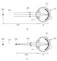
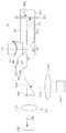
도 2는 제1 투사형 표시 유닛의 제1 예를 나타낸다.Fig. 2 shows a first example of the first projection type display unit.
제1 투사형 표시 유닛(161a)은 표시 소자(210) 및 도광부(30a)를 포함할 수 있다. 상기 도광부(30a)는 도광 소자(220a) 및 가변 렌즈(240a)를 포함할 수 있다. 이와 마찬가지로, 제2 투사형 표시 유닛은 표시 소자 및 도광부를 포함할 수 있고, 상기 도광부는 도광 소자 및 가변 렌즈를 포함할 수 있다.The first projection
상기 표시 소자(210)는 이미지를 형성하는 제1 광(201)을 상기 도광 소자(220a)로 출력할 수 있다. 상기 표시 소자(210)는 사각 평판의 형태를 가질 수 있다. 상기 표시 소자(210)는 프로세서로부터 입력된 데이터에 따라 픽셀 단위로 이미지를 표시할 수 있다. 상기 표시 소자(210)는 기설정된 해상도에 대응하는 픽셀 소자들을 구비하고, 상기 픽셀 소자들의 구동을 통해 이미지를 표시할 수 있다. 예를 들어, 상기 표시 소자(210)는 MxN(예를 들어, 1190x720, 854x480 등) 행렬 구조로 배열된 픽셀 소자들을 포함할 수 있다. 상기 표시 소자(210)는 LED(light emitting diode), OLED(organic light emitting diode), LCD(liquid crystal display), LCOS(liquid crystal on silicon) 등일 수 있다.The
상기 도광 소자(220a)는 제1 내지 제5 면들(221~225a)을 포함할 수 있다. 상기 도광 소자(220a)는 내부 반사(또는 내부 전반사)를 통해 상기 표시 소자(210)로부터 입력된 제1 광(201)을 가변 렌즈(240a)를 향해 가이드할 수 있다.The
상기 제1 면(221)은 상기 표시 소자(210)와 대면하는 상기 도광 소자(220a)의 후면의 일부분에 해당하며, 상기 표시 소자(210)로부터 입력된 제1 광(201)을 상기 제2 면(222)을 향해 투과시킬 수 있다.The
상기 제2 면(222)은 상기 제1 및 제3 면들(221, 223)의 사이에 위치하는 상기 도광 소자(220a)의 제1 측면에 해당하며, 상기 제1 면(221)을 투과한 제1 광(201)을 상기 제3 또는 제4 면(223, 224)을 향해 반사시킬 수 있다.The
상기 제3 면(223)은 제1 윈도우(90)와 대면하는 상기 도광 소자(220a)의 전면에 해당하며, 상기 제4 면(224)은 사용자와 대면하는 상기 도광 소자(220a)의 후면의 나머지 부분에 해당하며, 상기 제3 및 제4 면들(223, 224)은 각각 입사된 상기 제1 광(201)을 반사(또는 전반사)시켜서 상기 제1 광(201)이 상기 제5 면(225a)에 도달하도록 할 수 있다. 전반사는, 상기 도광 소자(220a) 및 외부 공기층의 경계면(즉, 상기 제3 또는 제4 면(223, 224))에서 상기 도광 소자(220)의 내부로부터 상기 경계면에 입사한 제1 광(201)이 투과 없이 모두 반사되는 것을 말한다.The
상기 제5 면(225a)은 상기 제3 및 제4 면들(223, 224)의 사이에 위치하는 상기 도광 소자(220a)의 제2 측면에 해당하며, 입사된 제1 광(201)을 상기 가변 렌즈(240a)를 향해 투과시키고, 상기 가변 렌즈(240a)로부터 입사된 제1 광(201)을 사용자의 눈을 향해 반사할 수 있다. 상기 제5 면(225a)은 상기 웨어러블 장치(101)의 전방의 뷰(또는 뷰의 광학적 이미지)를 형성하는 제2 광(202)을 사용자의 눈을 향해 투과시킬 수 있다.The
상기 도광 소자(220a)는, 두께가 일정한 제3 및 제4 광학면들(223, 224) 사이의 본체부(232a)와, 상기 본체부(232a)로부터 멀어질수록 점차 두께가 감소하는 제1 및 제2 면들(221, 222) 사이의 제1 경사부(231)와, 상기 본체부(232)로부터 멀어질수록 점차 두께가 감소하는 제3 및 제4 면들(223, 224) 사이의 제2 경사부(233a)를 포함할 수 있다. 상기 제2 경사부(233a)는 상기 가변 렌즈(240a) 및 사용자의 눈과 대면하는 경사면인 제5 면(225a)을 가질 수 있다.The
상기 가변 렌즈(240a)는 입사된 제1 광(201)을 투과시키는 투과면(241), 입사된 제1 광(201)을 굴절시키는 굴절면(242) 및 입사된 제1 광을 반사하는 반사면(243a)을 포함할 수 있다. 상기 굴절면(242)의 형태 또는 곡률은 프로세서의 제어에 따라 변화될 수 있다. 상기 가변 렌즈(240a)는 상기 굴절면(242)의 형태 또는 곡률의 변화에 따라 상기 제1 광(201)이 사용자의 눈에 입사하는 각도(즉, 입사각)을 조절함으로써, 전자 장치(예: 전자 장치(101)) 전방의 실제 뷰(또는 뷰의 광학적 이미지) 상에 표시되는 가상 이미지의 위치(또는 사용자의 눈으로부터 가상 물체까지의 가상 물체 거리)를 조절할 수 있다.The
도 3은 눈의 초점 조절을 설명하기 위한 도면이다.3 is a view for explaining focus control of the eye.
사용자의 눈(310)은 수정체(311) 및 망막(312)을 포함한다.The user's
상기 수정체(311)는 초점을 맺고자 하는 물체의 거리(즉, 물체 거리)에 따라서 면(전면 및 후면의 각각)의 곡률이 변경되며, 얇은 두께로 변형된 경우(즉, 면의 곡률이 작은 경우) 원거리의 물체에 눈의 초점이 맞게 되고, 두꺼운 두께로 변형된 경우(즉, 면의 곡률이 큰 경우) 근거리의 물체에 눈의 초점이 맞게 된다.The curvature of the surface (each of the front surface and the rear surface) changes according to the distance (i.e., the object distance) of the object to be focused, and when the
도 3의 (a)를 참조하면, 상기 수정체(311)는 얇은 두께로 변형되고(또는 그 면의 곡률이 감소되고), 원거리의 물체(320)에 눈(310)의 초점이 맞게 된다. 원거리 물체(320)로부터 출발한 광(325)은 상기 눈(310)의 광축(313)에 평행하게 진행하여 상기 수정체(311)에 입사하고, 상기 수정체(311)는 상기 광(325)을 굴절시켜서 상기 망막(312) 상에 수렴시킨다. 즉, 상기 수정체(311)는 상기 원거리 물체(320)의 이미지를 상기 망막(312) 상에 형성한다. 예를 들어, 상기 원거리 물체(320)(또는 상기 물체의 이미지)가 초점이 맞는 상태(즉, 인 포커스 상태)인 경우, 상기 수정체(311)로부터 상기 원거리 물체까지의 거리를 제1 물체 거리(OD1)라고 하고, 상기 수정체(311)로부터 상기 망막(312)까지의 거리를 상거리(ID)라고 할 수 있다. 물체 거리 및 상거리는 눈의 광축을 따라 측정된 거리들일 수 있다.3 (a), the
도 3의 (b)를 참조하면, 상기 수정체(311)는 두꺼운 두께로 변형되고(또는 그 면의 곡률이 증가되고), 근거리의 물체(330)에 눈(310)의 초점이 맞게 된다. 근거리 물체(330)로부터 출발한 광(335)은 상기 눈(310)의 광축(313)을 따라 발산(또는 확산)하면서 상기 수정체(311)에 입사하고, 상기 수정체(311)는 상기 광(335)을 굴절시켜서 상기 망막(312) 상에 수렴시킨다. 즉, 상기 수정체(311)는 상기 근거리 물체(330)의 이미지를 상기 망막(312) 상에 형성한다. 예를 들어, 상기 근거리 물체(또는 상기 근거리 물체의 이미지)가 인 포커스 상태인 경우, 상기 수정체(311)로부터 상기 근거리 물체(330)까지의 거리를 제2 물체 거리(OD2)라고 하고, 상기 수정체(311)로부터 상기 망막(312)까지의 거리를 상거리(ID)라고 할 수 있다.Referring to FIG. 3 (b), the
물체의 거리에 따라 상기 수정체가 변형하여 초점을 맞추므로, 인 포커스 상태에서, 물체의 거리 변화에 따라 상거리는 일정하고 물체 거리는 변화한다.Since the lens changes its focus according to the distance of the object, the normal distance is constant and the object distance changes in accordance with the distance change of the object in the in-focus state.
사용자의 눈에 보이는 물체는 실제 물체이거나, 가상 물체(예: 표시 소자 상의 이미지)일 수 있다.The object visible to the user may be an actual object or a virtual object (e.g., an image on a display element).
눈의 초점이 근거리 물체에 맞춰 있는 경우, 상기 근거리 물체의 이미지는 선명하게(즉, 초점이 맞는 상태(즉, 인 포커스 상태)로) 형성되고, 원거리 물체의 이미지는 흐릿하게(즉, 초점이 맞지 않는 상태(즉, 아웃 오브 포커스 상태)로) 형성된다.If the eye focuses on a near object, the image of the near object is formed vividly (i.e., in a focused state (i.e., in focus state)) and the image of the far object is blurred (I.e., in an out-of-focus state).
이와 반대로, 눈의 초점이 원거리 물체에 맞춰 있는 경우, 상기 원거리 물체의 이미지는 선명하게(즉, 인 포커스 상태로) 형성되고, 근거리 물체의 이미지는 흐릿하게(즉, 아웃 오브 포커스 상태로) 형성된다.On the contrary, when the focus of the eye is aligned with the far object, the image of the far object is formed clearly (i.e., in the in-focus state), and the image of the near object is blurred do.
예를 들어, 원거리의 실제 물체와, 상기 실제 물체의 정보를 표시하는 근거리의 가상 물체가 중첩되어 보이는 경우, 이러한 증강 현실의 몰입도가 저하되거나, 사용자가 어지러움을 느낄 수 있다.For example, when a real object at a distance is overlapped with a near virtual object displaying information of the real object, the degree of immersion of the augmented reality may be reduced or the user may feel dizziness.
도 4는 가변 렌즈에 의한 가상 물체 거리의 조절을 설명하기 위한 도면이다.4 is a view for explaining adjustment of a virtual object distance by a variable lens.
상기 가변 렌즈(240a)는 프로세서의 제어에 따라 사용자의 눈(310)에 입사하는 제1 광(411)의 입사각을 조절함으로써, 전자 장치(예: 전자 장치(101)) 전방의 실제 뷰(또는 뷰의 광학적 이미지) 상에 표시되는 가상 이미지의 위치(또는 사용자의 눈(310)으로부터 사용자가 인식하는 가상 물체(421)까지의 가상 물체 거리)를 조절할 수 있다.The
도 4의 (a)를 참조하면, 상기 수정체(311)는 얇은 두께로 변형되고, 원거리의 실제 물체(320)에 눈의 초점이 맞게 된다. 원거리의 실제 물체(320)로부터 출발한 제2 광(325)은, 상기 눈(310)의 광축(313)에 평행하게 진행하고, 상기 도광 소자(220a)의 제5 면(225a)을 투과하여 상기 수정체(311)에 입사하고, 상기 수정체(311)는 상기 제2 광(325)을 굴절시켜서 상기 망막(312) 상에 수렴시킨다. 즉, 상기 수정체(311)는 상기 실제 물체의 이미지를 상기 망막(312) 상에 형성한다.Referring to FIG. 4 (a), the
상기 가변 렌즈(240a)는 제1 광(411)을 상기 제5 면(225a)에 투사할 수 있다. 상기 제5 면(225a)으로부터 반사된 제1 광(411)은, 상기 눈(310)의 광축(313)에 평행하게 진행하여 상기 수정체(311)에 입사하고, 상기 수정체(311)는 상기 제1 광(411)을 굴절시켜서 상기 망막(312) 상에 수렴시킬 수 있다. 즉, 상기 수정체(311)는 가상 물체(421)의 이미지를 상기 망막(312) 상에 형성할 수 있다. 예를 들어, 상기 실제 물체(320)(또는 상기 실제 물체(320)의 이미지)가 인 포커스 상태인 경우, 상기 실제 물체(320)(또는 상기 실제 물체(320)의 이미지) 및 상기 가상 물체(421)(또는 상기 가상 물체(421)의 이미지)는 동일한 제1 물체 거리(OD1) 및 상거리(ID)를 가질 수 있다.The
도 4의 (b)를 참조하면, 상기 수정체(311)는 두꺼운 두께로 변형되고, 근거리의 실제 물체(330)에 눈의 초점이 맞게 된다. 근거리의 실제 물체(330)로부터 출발한 제2 광(335)은, 상기 눈(310)의 광축(313)을 따라 발산(또는 확산)하면서 진행하고, 상기 도광 소자(220a)의 제5 면(225a)을 투과하여 상기 수정체(311)에 입사하고, 상기 수정체(311)는 상기 제2 광(335)을 굴절시켜서 상기 망막(312) 상에 수렴시킨다. 즉, 상기 수정체(311)는 상기 실제 물체(330)의 이미지를 상기 망막(312) 상에 형성한다. 상기 가변 렌즈(240a)는 제1 광(412)을 상기 제5 면(225a)에 투사할 수 있다. 상기 제5 면(225a)으로부터 반사된 제1 광(412)은, 상기 눈(310)의 광축(313)을 따라 발산(또는 확산)하면서 진행하여 상기 수정체(311)에 입사하고, 상기 수정체(311)는 상기 제1 광(412)을 굴절시켜서 상기 망막(312) 상에 수렴시킬 수 있다. 즉, 상기 수정체(311)는 가상 물체(422)의 이미지를 상기 망막(312) 상에 형성할 수 있다. 예를 들어, 상기 실제 물체(330)(또는 상기 실제 물체(330)의 이미지)가 인 포커스 상태인 경우, 상기 실제 물체(330)(또는 상기 실제 물체(330)의 이미지) 및 상기 가상 물체(422)(또는 상기 가상 물체(422)의 이미지)는 동일한 제2 물체 거리(OD2) 및 상거리(ID)를 가질 수 있다.Referring to FIG. 4B, the
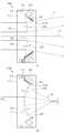
도 5a는 가변 렌즈의 제1 예를 나타내는 도면이다.5A is a diagram showing a first example of a variable lens.
도 5a의 (a)를 참조하면, 상기 가변 렌즈(240a)는, 제1 및 제2 기판들(510, 530), 제1 및 제2 전극들(540, 550), 제1 액체 및 제2 액체(521, 522)를 포함할 수 있다.5A, the
상기 제1 기판(510)은 투명 평판일 수 있으며, 도광 소자(220a)로부터 입력된 제1 광(560)을 투과시킬 수 있다. 상기 제1 기판(510)의 전면은 투과면(241)에 해당할 수 있다.The
상기 제2 기판(530)은 투명 또는 불투명 평판일 수 있으며, 상기 제1 기판(510)과 상기 제1 액체(521) 및 상기 제2 액체(522)을 차례로 투과한 제1 광(560)을 상기 도광 소자(220a)를 향해 반사할 수 있다. 상기 제2 기판(530)의 전면은 반사면(243a)에 해당할 수 있다.The
상기 제1 전극(540)은 상기 제1 기판(510)의 후면의 가장자리에 형성될 수 있다. 상기 제1 전극(540)의 면에 전기 절연 특성을 갖는 제1 절연층(545)이 형성될 수 있다.The
상기 제2 전극(550)은 상기 제2 기판(530)의 전면의 가장자리에 형성될 수 있다. 상기 제2 전극(550)의 면에 전기 절연 특성을 갖는 제2 절연층(555)이 형성될 수 있다.The
상기 제1 액체(521) 및 상기 제2 액체(522)는 상기 가변 렌즈(240a)의 내부 공간에 충진될 수 있으며, 상기 제1 기판(510) 및 상기 제2 기판(530)의 사이에 배치될 수 있다. 상기 제1 액체(521) 및 상기 제2 액체(522)는 서로 섞이지 않으며, 상기 제2 액체(522)의 굴절률은 상기 제1 액체(521)의 굴절률보다 클 수 있다. 예를 들어, 상기 제1 액체(521)는 물이고, 상기 제2 액체(522)는 기름일 수 있다. 상기 제1 액체(521) 및 상기 제2 액체(522)의 경계면은 굴절면(242)에 해당할 수 있다.The
프로세서는 상기 제1 전극(540) 및 상기 제2 전극(550)에 인가되는 전압을 조절함으로써, 상기 굴절면(242)의 형태(또는, 굴절면(242)의 굴절력 또는 곡률)를 조절할 수 있다. 예를 들어, 굴절력은 평행 광에 대한 초점거리의 역수로 정의될 수 있다. 예를 들어, 상기 제1 전극(540)은 접지와 연결되고, 상기 제2 전극(550)에는 상기 프로세서의 제어 신호에 따른 제어 전압이 인가될 수 있다. 예를 들어, 오목한 굴절면은 음(-)의 곡률(또는 곡률반경)을 갖고, 볼록한 굴절면은 양(+)의 곡률(또는 곡률반경)을 갖는 것으로 볼 수 있다. 곡률은 곡률반경의 역수에 해당한다. 비구면인 굴절면의 경우에, 곡률은 굴절면의 정점(또는 굴절면과 광축이 만나는 점)에서의 곡률을 말할 수 있다.The processor may adjust the shape of the refracting surface 242 (or the refractive power or curvature of the refracting surface 242) by adjusting the voltage applied to the
예를 들어, 상기 굴절면(242)이 상기 제1 기판(510) 측에서 볼 때 오목한 경우, 상기 가변 렌즈(240a)는 양면 오목 렌즈와 같은 기능을 수행할 수 있다. 광축에 평행하게 진행하는 제1 광(560)은 상기 제1 기판(510)을 투과하여 상기 굴절면(242)에서 광축(244)으로부터 멀어지는 방향으로 1차 굴절되고, 상기 제1 광(560)은 상기 반사면(243a)에서 반사될 수 있다. 상기 반사된 제1 광(560)은 상기 굴절면(242)에서 광축(244)으로부터 멀어지는 방향으로 2차 굴절되고, 상기 2차 굴절된 제1 광은 상기 제1 기판(510)을 투과할 수 있다.For example, when the refracting
도 5a의 (b)를 참조하면, 예를 들어, 상기 굴절면(242)이 상기 제1 기판(510) 측에서 볼 때 볼록한 경우, 상기 가변 렌즈(240a)는 양면 볼록 렌즈와 같은 기능을 수행할 수 있다. 광축(244)에 평행하게 진행하는 제1 광(565)은 상기 제1 기판(510)을 투과하여 상기 굴절면(242)에서 광축(244)에 가까워지는 방향으로 1차 굴절되고, 상기 제1 광(565)은 상기 반사면(243a)에서 반사될 수 있다. 상기 반사된 제1 광(565)은 상기 굴절면(242)에서 광축(244)에 가까워지는 방향으로 2차 굴절되고, 상기 2차 굴절된 제1 광(560)은 상기 제1 기판(510)을 투과할 수 있다.Referring to FIG. 5A, when the refracting
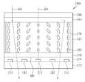
도 5b는 가변 렌즈의 제2 예를 나타내는 도면이다.5B is a view showing a second example of the variable lens.
도 5b의 (a)를 참조하면, 상기 가변 렌즈(240d)는, 제1 및 제2 기판들(572, 586), 절연층(574), 복수의 전극들(EL1, EL2, EL3), 제1 및 제2 배향막들(576, 584), 액정층(578) 및 실런트(582)를 포함할 수 있다.Referring to FIG. 5B, the
상기 제1 및 제2 기판들(572, 586)은 각각 플라스틱 또는 유리로 형성될 수 있다.The first and
상기 절연층(574)은 상기 제1 기판(572)의 표면(또는 상면) 상에 배치될 수 있고, 절연성을 갖는 유기 물질 또는 무기 물질로 형성될 수 있다.The insulating
상기 복수의 전극들(EL1, EL2, EL3)은 상기 제1 기판(572)의 표면(또는 상면) 상에 배치될 수 있고, 상기 절연층(574) 내에 배치될 수 있다. 인듐 틴 옥사이드(ITO) 등과 같은 투명 도전 물질로 형성될 수 있다.The plurality of electrodes EL1, EL2, and EL3 may be disposed on the surface (or the upper surface) of the
상기 제1 배향막(576)은 상기 절연층(574)의 표면(또는 상면) 상에 배치될 수 있고, 상기 액정층(578) 내의 액정 분자들(580)을 선경사(pretilt)시키는 기능을 수행할 수 있다.The
상기 액정층(578)은 상기 제1 배향막(576)의 표면(또는 상면) 상에 배치될 수 있고, 상기 복수의 전극들(EL1, EL2, EL3)에 의해 인가된 전기장의 세기에 따라 배치 방향이 조절되는 복수의 액정 분자들(580)을 포함할 수 있다.The
상기 제2 배향막(584)은 상기 액정층(578)의 표면(또는 상면) 상에 배치될 수 있고, 상기 액정층(578) 내의 액정 분자들(580)을 선경사(pretilt)시키는 기능을 수행할 수 있다.The
상기 제2 기판(586)은 상기 제2 배향막(584)의 표면(또는 상면) 상에 배치될 수 있다.The
상기 실런트(582)는 상기 액정층(578)의 측면(들)을 둘러싸도록 상기 제1 및 제2 배향막들(576, 584)의 사이에 배치될 수 있고, 상기 액정층(578)을 밀폐하는 기능을 수행할 수 있다.The
상기 제1 배향막(576) 및 상기 절연층(574)의 사이(또는, 상기 제1 배향막(576), 상기 절연층(574) 및 상기 제1 기판(572) 중 어느 한 층의 표면)에는, 입사된 제1 광(590)을 반사하는 반사면(588)(또는 반사층)이 배치될 수 있다.(Or the surface of any one of the
도시되지 않았으나, 예를 들어, 무늬가 없는 평판 형태의 접지 전극이 상기 제2 기판(586) 및 상기 제2 배향막(584) 중 어느 한 층의 표면 상에 배치될 수 있다.Although not shown, for example, a grounded electrode in the form of a flat plate may be disposed on the surface of any one of the
한 실시예에서, 제1 광(590)은 외부로부터 제1 기판(572)으로 입사될 수 있고, 접지 전극이 반사면의 기능을 수행하거나, 상기 제2 기판(586) 및 상기 제2 배향막(584) 중 어느 한 층의 표면에 반사면(588)이 배치될 수도 있다.In one embodiment, the
프로세서는 상기 복수의 전극들(EL1, EL2, EL3)에 인가되는 전압을 조절함으로써, 액정 분자들(580)의 배치 방향들을 조절할 수 있다.The processor can adjust the placement directions of the
예를 들어, 상기 액정층(578)의 폭 방향을 기준으로 하여, 프로세서는 중앙 위치로부터 가장자리 위치로 갈수록 상기 복수의 전극들(EL1, EL2, EL3)에 인가되는 전압을 증가 또는 감소시킴으로써, 액정 분자들(580)의 배치 방향들의 분포(또는 프로파일)를 조절할 수 있다. 예를 들어, 상기 액정층(578)의 폭 방향을 기준으로 하여, 프로세서는 중앙 위치로부터 가장자리 위치로 갈수록 상기 복수의 전극들(EL1, EL2, EL3)에 인가되는 전압을 증가(또는 감소)시킴으로써, 중앙 위치로부터 가장자리 위치로 갈수록 상기 제1 기판(572)의 표면(또는 상면)을 기준으로 한 액정 분자들(580)의 경사각들이 점차 증가하도록(또는 감소하도록) 할 수 있다. 예를 들어, 중앙 위치의 액정 분자들(580)은 제1 전극(EL1)에 가장 낮은 전압이 인가됨에 따라 장축이 상기 제1 기판(572)의 표면과 수평을 이루도록 배치될 수 있다. 중간 위치의 액정 분자들(580)은 제2 전극들(EL2)에 중간 전압이 인가됨에 따라 장축이 상기 제1 기판(572)의 표면과 수직인 아닌 경사를 이루도록 배치될 수 있다. 가장자리 위치의 액정 분자들(580)은 제3 전극들(EL3)에 가장 높은 전압이 인가됨에 따라 장축이 상기 제1 기판(572)의 표면과 수직을 이루도록 배치될 수 있다.For example, with reference to the width direction of the
도 5b의 (b)에서, 가로축은 상기 액정층(578)의 폭 방향에 따른 위치를 나타내고, 세로축은 굴절률을 나타낸다. P1은 제1 전극(EL1)에 대응하는 위치를 나타내고, P2은 제2 전극(EL2)에 대응하는 위치를 나타내고, P3는 제3 전극(EL3)에 대응하는 위치를 나타낸다.In (b) of FIG. 5B, the abscissa represents the position along the width direction of the
도 5b의 (b)를 참조하면, 상기 액정층(578)의 폭 방향을 기준으로 하여, 중앙 위치로부터 가장자리 위치로 갈수록 상기 복수의 전극들(EL1, EL2, EL3)에 인가되는 전압이 증가됨으로써, 중앙 위치로부터 가장자리 위치로 갈수록 상기 제1 기판(572)의 표면(또는 상면)을 기준으로 한 액정 분자들(580)의 경사각들이 점차 증가될 수 있다. 중앙 위치로부터 가장자리 위치로 갈수록 액정 분자들(580)의 경사각들이 점차 증가됨으로써, 중앙 위치로부터 가장자리 위치로 갈수록 상기 액정층(578)의 굴절률이 점차 감소될 수 있다. 도 5b의 (b)에 도시된 바와 같은 굴절률 프로파일을 갖는 경우, 상기 가변 렌즈(240d)는 양면 볼록 렌즈와 같은 기능을 수행할 수 있다. 한 실시예에서, 프로세서는 중앙 위치로부터 가장자리 위치로 갈수록 상기 복수의 전극들(EL1, EL2, EL3)에 인가되는 전압을 감소시킴으로써, 상기 가변 렌즈(240d)가 양면 오목 렌즈와 같은 기능을 수행하도록 조절할 수 있다.Referring to FIG. 5B, the voltage applied to the plurality of electrodes EL1, EL2, and EL3 increases from the center position to the edge position with reference to the width direction of the
도 5b의 (a)를 참조하면, 제1 광(590)은 상기 제2 기판(586) 및 상기 제2 배향막(584)을 차례로 투과하여 상기 액정층(578)에서 광축(594)에 가까워지는 방향으로 1차 굴절되고, 상기 제1 광(590)은 상기 반사면(588)에서 반사될 수 있다. 상기 반사된 제1 광(590)은 상기 액정층(578)에서 광축(594)에 가까워지는 방향으로 2차 굴절되고, 상기 2차 굴절된 제1 광(590)은 상기 제2 배향막(584) 및 상기 제2 기판(586)을 차례로 투과할 수 있다.Referring to FIG. 5B, the
한 실시예에서, 상기 가변 렌즈(240d)는 도 5a에 도시된 가변 렌즈(240a)를 대체하여 사용될 수 있다.In one embodiment, the
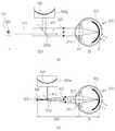
도 6은 제1 투사형 표시 유닛의 제2 예를 나타낸다. 상기 제1 투사형 표시 유닛(161b)은 도 2에 도시된 제1 투사형 표시 유닛(161a)과 유사한 구성을 가지며, 단지 가변 렌즈의 구성 및 위치가 변경되고, 미러를 더 포함한다는 점에서 차이가 있으므로, 중복되는 설명은 생략하기로 한다.6 shows a second example of the first projection type display unit. The first projection
제1 투사형 표시 유닛(161b)은 표시 소자(210) 및 도광부(30b)를 포함할 수 있다. 상기 도광부(30b)는 도광 소자(220a), 미러(610) 및 가변 렌즈(240b)를 포함할 수 있다.The first projection
상기 제1 면(221)은 상기 제1 표시 소자(210)와 대면하는 상기 도광 소자(220a)의 후면의 일부분에 해당하며, 상기 표시 소자(210)로부터 출력된 후 상기 가변 렌즈(240b)를 투과하여 입사된 제1 광(601)을 상기 제2 면(222)을 향해 투과시킬 수 있다.The
상기 제5 면(225a)은 상기 제3 및 제4 면들(223, 224)의 사이에 위치하는 상기 도광 소자(220a)의 제2 측면에 해당하며, 입사된 제1 광(601)을 상기 미러(610)를 향해 투과시키고, 상기 미러(610)로부터 입사된 제1 광(601)을 사용자의 눈을 향해 반사할 수 있다. 상기 제5 면(225a)은 상기 웨어러블 장치(101)의 전방의 뷰(또는 뷰의 광학적 이미지)를 형성하는 제2 광(602)을 사용자의 눈을 향해 투과시킬 수 있다.The
상기 미러(610)는 반사면(612)을 포함하며, 상기 반사면(612)은 상기 도광 소자(220a)로부터 입력된 제1 광(601)을 상기 제5 면(225a)을 향해 반사할 수 있다. 상기 반사면(612)은 일정한 곡률(또는 곡률 반경)을 갖는 구면 또는 비구면일 수 있다.The
상기 가변 렌즈(240b)는 상기 표시 소자(210)로부터 출력되어 입사된 상기 제1 광(601)을 투과시키는 제1 투과면(241), 상기 투과면(241)을 투과한 상기 제1 광(601)을 굴절시키는 굴절면(242) 및 상기 굴절면(242)을 투과한 상기 제1 광(601)을 투과시키는 제2 투과면(243b)을 포함할 수 있다. 상기 굴절면(242)의 형태 또는 곡률은 프로세서의 제어에 따라 변화될 수 있다. 상기 가변 렌즈(240b)는 상기 굴절면(242)의 형태 또는 곡률의 변화에 따라 사용자의 눈에 입사하는 상기 제1 광(601)의 입사각을 조절함으로써, 전자 장치(예: 전자 장치(101)) 전방의 실제 뷰(또는 뷰의 광학적 이미지) 상에 표시되는 가상 이미지의 위치(또는 사용자의 눈으로부터 가상 물체까지의 가상 물체 거리)를 조절할 수 있다.The
도 7a는 가변 렌즈의 제3 예를 나타내는 도면이다. 상기 가변 렌즈(240b)는 도 5a에 도시된 가변 렌즈(240a)와 유사한 구성을 가지며, 단지 반사면이 제2 투과면으로 대체되었다는 점에서 차이가 있으므로, 중복되는 설명은 생략하기로 한다.7A is a view showing a third example of the variable lens. The
도 7a의 (a)를 참조하면, 상기 가변 렌즈(240b)는 제1 및 제2 기판들(510, 530b), 제1 및 제2 전극들(540, 550), 제1 액체 및 제2 액체(521, 522)를 포함할 수 있다.Referring to FIG. 7A, the
상기 제1 기판(510)은 투명 평판일 수 있으며, 도광 소자(220)로부터 입사된 제1 광(701)을 투과시킬 수 있다. 상기 제1 기판(510)의 전면은 제1 투과면(241)에 해당할 수 있다.The
상기 제2 기판(530b)은 투명 평판일 수 있으며, 상기 제1 기판(510)과 상기 제1 액체(521) 및 상기 제2 액체(522)을 투과한 제1 광(701)을 투과시킬 수 있다. 상기 제2 기판(530b)의 전면 및 후면은 각각 제2 투과면(243b)에 해당할 수 있다.The
상기 제1 전극(540)은 상기 제1 기판(510)의 후면에 형성될 수 있다. 상기 제1 전극(540)의 면에 제1 절연층(545)이 형성될 수 있다.The
상기 제2 전극(550)은 상기 제2 기판(530b)의 전면에 형성될 수 있다. 상기 제2 전극(550)의 면에 제2 절연층(555)이 형성될 수 있다.The
상기 제1 액체(521) 및 상기 제2 액체(522)는 상기 가변 렌즈(240b)의 내부 공간에 충진될 수 있으며, 상기 제1 기판(510) 및 상기 제2 기판(530b)의 사이에 배치될 수 있다. 상기 제1 액체(521) 및 상기 제2 액체(522)는 서로 섞이지 않으며, 상기 제2 액체(522)의 굴절률은 상기 제1 액체(521)의 굴절률보다 클 수 있다. 예를 들어, 상기 제1 액체(521)는 물이고, 상기 제2 액체(522)는 기름일 수 있다. 상기 제1 액체(521) 및 상기 제2 액체(522)의 경계면은 굴절면(242)에 해당할 수 있다.The
프로세서는 상기 제1 전극(540) 및 상기 제2 전극(550)에 인가되는 전압을 조절함으로써, 상기 굴절면(242)의 형태를 조절할 수 있다. 예를 들어, 상기 제1 전극(540)는 접지와 연결되고, 상기 제2 전극(550)에는 상기 프로세서의 제어 신호에 따른 제어 전압이 인가될 수 있다.The processor may adjust the shape of the refracting
예를 들어, 상기 굴절면(242)이 상기 제1 기판 측에서 볼 때 오목한 경우, 상기 가변 렌즈(240b)는 오목 렌즈(또는 오목-평면 렌즈)와 같은 기능을 수행할 수 있다. 광축(244)에 평행하게 진행하는 제1 광(701)은 상기 제1 기판(510)을 투과하여 상기 굴절면(242)에서 광축(244)으로부터 멀어지는 방향으로 굴절되고, 상기 굴절된 제1 광(701)은 상기 제2 기판(530b)을 투과할 수 있다.For example, when the refracting
도 7a의 (b)를 참조하면, 예를 들어, 상기 굴절면(242)이 상기 제1 기판(510) 측에서 볼 때 볼록한 경우, 상기 가변 렌즈(240b)는 양면 볼록 렌즈와 같은 기능을 수행할 수 있다. 광축(244)에 평행하게 진행하는 제1 광(702)은 상기 제1 기판(510)을 투과하여 상기 굴절면(242)에서 광축(244)에 가까워지는 방향으로 1차 굴절되고, 상기 굴절된 제1 광(244)은 상기 제2 기판(530b)을 투과할 수 있다.Referring to FIG. 7A, when the refracting
도 7b는 가변 렌즈의 제4 예를 나타내는 도면이다. 상기 가변 렌즈(240e)는 도 5b에 도시된 가변 렌즈(240d)와 유사한 구성을 가지며, 단지 반사면이 제거되었다는 점에서 차이가 있으므로, 중복되는 설명은 생략하기로 한다.7B is a view showing a fourth example of the variable lens. The
상기 가변 렌즈(240e)는, 제1 및 제2 기판들(572, 586), 절연층(574), 복수의 전극들(EL1, EL2, EL3), 제1 및 제2 배향막들(576, 584), 액정층(578) 및 실런트(582)를 포함할 수 있다.The
제1 광(595)은 상기 제2 기판(586) 및 상기 제2 배향막(584)을 차례로 투과하여 상기 액정층(578)에서 광축(594)에 가까워지는 방향으로 굴절될 수 있다. 상기 굴절된 제1 광(595)은 상기 제1 배향막(576), 상기 절연층(574) 및 상기 제1 기판(572)을 차례로 투과할 수 있다.The
한 실시예에서, 상기 가변 렌즈(240e)는 도 7a에 도시된 가변 렌즈(240b)를 대체하여 사용될 수 있다.In one embodiment, the
도 8은 제1 투사형 표시 유닛의 제3 예를 나타낸다. 상기 제1 투사형 표시 유닛(161c)은 도 6에 도시된 제1 투사형 표시 유닛(161b)과 유사한 구성을 가지며, 단지 미러를 제거하고, 제5 면이 반사면으로서 기능한다는 점에서 차이가 있으므로, 중복되는 설명은 생략하기로 한다.8 shows a third example of the first projection type display unit. The first
제1 투사형 표시 유닛(161c)은 표시 소자(210) 및 도광부(30c)를 포함할 수 있다. 상기 도광부(30c)는 도광 소자(220b) 및 가변 렌즈(240b)를 포함할 수 있다.The first projection
상기 제5 면(225b)은 상기 제3 및 제4 면들(223, 224)의 사이에 위치하는 상기 도광 소자(220b)의 제2 측면에 해당하며, 입사된 제1 광(801)을 사용자의 눈을 향해 반사할 수 있다. 상기 제5 면(225b)은 상기 웨어러블 장치(101)의 전방의 뷰(또는 뷰의 광학적 이미지)를 형성하는 제2 광(602)을 사용자의 눈을 향해 투과시킬 수 있다.The
상기 도광 소자(220b)는, 두께가 일정한 제3 및 제4 광학면들(223, 224) 사이의 본체부(232a)와, 상기 본체부(232a)로부터 멀어질수록 점차 두께가 감소하는 제1 및 제2 면들(221, 222) 사이의 제1 경사부(231)와, 상기 본체부(232a)로부터 멀어질수록 점차 두께가 감소하는 제3 및 제4 면들(223, 224) 사이의 제2 경사부(233b)를 포함할 수 있다. 상기 제2 경사부(233b)는 상기 웨어러블 장치(101)의 전방의 뷰와 대면하는 경사면인 제5 면(225b)을 가질 수 있다.The
도 9는 제1 투사형 표시 유닛의 제4 예를 나타낸다. 상기 제1 투사형 표시 유닛(161d)은 도 6에 도시된 제1 투사형 표시 유닛(161b)과 유사한 구성을 가지며, 단지 가변 렌즈의 위치가 변경된다는 점에서 차이가 있으므로, 중복되는 설명은 생략하기로 한다.9 shows a fourth example of the first projection type display unit. The first projection
제1 투사형 표시 유닛(161d)은 표시 소자(210) 및 도광부(30d)를 포함할 수 있다. 상기 도광부(30d)는 도광 소자(220c), 미러(610) 및 가변 렌즈(240b)를 포함할 수 있다.The first projection
상기 제1 면(221)은 상기 표시 소자(210)와 대면하는 상기 도광 소자(220c)의 후면의 일부분에 해당하며, 상기 표시 소자(210)로부터 입력된 제1 광(901)을 상기 제2 면(222)을 향해 투과시킬 수 있다.The
상기 제3 면(223)은 제1 윈도우(90)와 대면하는 상기 도광 소자(220c)의 전면에 해당하며, 상기 제4 면(224)은 사용자와 대면하는 상기 도광 소자(220c)의 후면의 나머지 부분에 해당하며, 상기 제3 및 제4 면들(223, 224)은 각각 입사된 상기 제1 광(901)을 반사(또는 전반사)시켜서 상기 제1 광(901)이 상기 제5 면(225a)에 도달하도록 할 수 있다.The
상기 도광 소자(220c)는, 두께가 일정한 제3 및 제4 광학면들(223, 224) 사이의 본체부(232b)와, 상기 본체부(232b)로부터 멀어질수록 점차 두께가 감소하는 제1 및 제2 면들(221, 222) 사이의 제1 경사부(231)와, 상기 본체부(232b)로부터 멀어질수록 점차 두께가 감소하는 제3 및 제4 면들(223, 224) 사이의 제2 경사부(233a)를 포함할 수 있다.The
상기 가변 렌즈(240b)는 상기 본체부(232b)의 중간에 삽입될 수 있다. 상기 본체부(232b)는 상기 가변 렌즈(240b)의 수용을 위한 홈 또는 홀을 구비하거나, 서로 이격된 2부분들로 구성될 수 있다. 상기 가변 렌즈(240b)는 상기 본체부(232b)의 내부로 진행하는 제1 광을 투과시키는 제1 투과면(241), 상기 투과면(241)면을 투과한 상기 제1 광을 굴절시키는 굴절면(242) 및 상기 굴절면(242)을 투과한 상기 제1 광을 투과시키는 제2 투과면(243b)을 포함할 수 있다. 상기 굴절면(242)의 형태 또는 곡률은 프로세서의 제어에 따라 변화될 수 있다. 상기 가변 렌즈(240b)는 상기 굴절면(242)의 형태 또는 곡률의 변화에 따라 사용자의 눈에 입사하는 상기 제1 광(901)의 입사각을 조절함으로써, 전자 장치(예: 전자 장치(101)) 전방의 실제 뷰(또는 뷰의 광학적 이미지) 상에 표시되는 가상 이미지의 위치(또는 사용자의 눈으로부터 가상 물체까지의 가상 물체 거리)를 조절할 수 있다.The
도 10은 제1 투사형 표시 유닛의 제5 예를 나타낸다. 상기 제1 투사형 표시 유닛(161e)은 도 8에 도시된 제1 투사형 표시 유닛(161c)과 유사한 구성을 가지며, 단지 가변 렌즈의 위치가 변경된다는 점에서 차이가 있으므로, 중복되는 설명은 생략하기로 한다.10 shows a fifth example of the first projection type display unit. The first projection
제1 투사형 표시 유닛(161e)은 표시 소자(210) 및 도광부(30e)를 포함할 수 있다. 상기 도광부(30e)는 도광 소자(220d) 및 가변 렌즈(240b)를 포함할 수 있다.The first projection
상기 제1 면(221)은 상기 표시 소자(210)와 대면하는 상기 도광 소자(220d)의 후면의 일부분에 해당하며, 상기 표시 소자(210)로부터 입력된 제1 광(1001)을 상기 제2 면(222)을 향해 투과시킬 수 있다.The
상기 제3 면(223)은 제1 윈도우(90)와 대면하는 상기 도광 소자(220d)의 전면에 해당하며, 상기 제4 면(224)은 사용자와 대면하는 상기 도광 소자(220d)의 후면의 나머지 부분에 해당하며, 상기 제3 및 제4 면들(223, 224)은 각각 입사된 상기 제1 광(1001)을 반사(또는 전반사)시켜서 상기 제1 광(1001)이 상기 제5 면(225b)에 도달하도록 할 수 있다.The
상기 도광 소자(220d)는, 두께가 일정한 제3 및 제4 광학면들(223, 224) 사이의 본체부(232b)와, 상기 본체부(232b)로부터 멀어질수록 점차 두께가 감소하는 제1 및 제2 면들(221, 222) 사이의 제1 경사부(231)와, 상기 본체부(232b)로부터 멀어질수록 점차 두께가 감소하는 제3 및 제4 면들(223, 224) 사이의 제2 경사부(233b)를 포함할 수 있다. 상기 제2 경사부(233b)는 상기 웨어러블 장치(101)의 전방의 뷰와 대면하는 경사면인 제5 면(225b)을 가질 수 있다.The
상기 가변 렌즈(240b)는 상기 본체부(232b)의 중간에 삽입될 수 있다. 상기 본체부(232b)는 상기 가변 렌즈(240b)의 수용을 위한 홈 또는 홀을 구비하거나, 서로 이격된 2부분들로 구성될 수 있다. 상기 가변 렌즈(240b)는 상기 본체부(232b)의 내부로 진행하는 제1 광을 투과시키는 제1 투과면(241), 상기 투과면(241)면을 투과한 상기 제1 광을 굴절시키는 굴절면(242) 및 상기 굴절면(242)을 투과한 상기 제1 광을 투과시키는 제2 투과면(243b)을 포함할 수 있다. 상기 굴절면(242)의 형태 또는 곡률은 프로세서의 제어에 따라 변화될 수 있다. 상기 가변 렌즈(240b)는 상기 굴절면(242)의 형태 또는 곡률의 변화에 따라 사용자의 눈에 입사하는 상기 제1 광(1001)의 입사각을 조절함으로써, 전자 장치(예: 전자 장치(101)) 전방의 실제 뷰(또는 뷰의 광학적 이미지) 상에 표시되는 가상 이미지의 위치(또는 사용자의 눈으로부터 가상 물체까지의 가상 물체 거리)를 조절할 수 있다.The
도 11은 제1 투사형 표시 유닛의 제6 예를 나타낸다. 상기 제1 투사형 표시 유닛(161f)은 도 6에 도시된 제1 투사형 표시 유닛(161b)과 유사한 구성을 가지며, 단지 가변 렌즈의 구성이 변경되고, 도 12에 도시된 렌즈 구동부(1200)가 추가된다는 점에서 차이가 있으므로, 중복되는 설명은 생략하기로 한다. 도 11에서, 렌즈 구동부(1200)는 생략되어 있다.11 shows a sixth example of the first projection type display unit. The first projection
제1 투사형 표시 유닛(161f)은 표시 소자(210), 도광부(30f) 및 렌즈 구동부를 포함할 수 있다. 상기 도광부(30f)는 도광 소자(220a), 미러(610) 및 가변 렌즈(240c)를 포함할 수 있다.The first projection
상기 제1 면(221)은 상기 제1 표시 소자(210)와 대면하는 상기 도광 소자(220a)의 후면의 일부분에 해당하며, 상기 표시 소자(210)로부터 출력된 후 상기 가변 렌즈(240c)를 투과하여 입사된 제1 광(1101)을 상기 제2 면(222)을 향해 투과시킬 수 있다.The
상기 제5 면(225a)은 상기 제3 및 제4 면들(223, 224)의 사이에 위치하는 상기 도광 소자(220a)의 제2 측면에 해당하며, 입사된 제1 광(1101)을 상기 미러(610)를 향해 투과시키고, 상기 미러(610)로부터 입사된 제1 광(1101)을 사용자의 눈을 향해 반사할 수 있다. 상기 제5 면(225a)은 상기 웨어러블 장치(101)의 전방의 뷰(또는 뷰의 광학적 이미지)를 형성하는 제2 광(602)을 사용자의 눈을 향해 투과시킬 수 있다.The
상기 미러(610)는 반사면(612)을 포함하며, 상기 반사면(612)은 상기 도광 소자(220a)로부터 입력된 제1 광을 상기 제5 면(225a)을 향해 반사할 수 있다. 상기 반사면(612)은 일정한 곡률(또는 곡률 반경)을 갖는 구면 또는 비구면일 수 있다.The
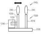
상기 가변 렌즈(240c)는 상기 표시 소자(210)로부터 출력되어 입사된 상기 제1 광(1101)을 1차 굴절시키는 제1 서브 렌즈(245) 및 상기 1차 굴절된 제1 광(1101)을 2차 굴절시키는 제2 서브 렌즈(246)를 포함할 수 있다. 상기 제1 및 제2 서브 렌즈들(245, 246) 사이의 거리는 프로세서의 제어에 따라 변화될 수 있다. 상기 가변 렌즈(240c)는 상기 제1 및 제2 서브 렌즈들(245, 246) 사이의 거리의 변화에 따라 사용자의 눈에 입사하는 상기 제1 광(1101)의 입사각을 조절함으로써, 전자 장치(예: 전자 장치(101)) 전방의 실제 뷰(또는 뷰의 광학적 이미지) 상에 표시되는 가상 이미지의 위치(또는 사용자의 눈으로부터 가상 물체까지의 가상 물체 거리)를 조절할 수 있다.The
도 12는 렌즈 구동부의 일 예를 나타낸다.12 shows an example of a lens driving unit.
상기 렌즈 구동부(1200)는, 제1 및 제2 지지부들(1210, 1220), 가이드(1230) 및 액추에이터(1240)를 포함할 수 있다.The
상기 제1 지지부(1210)는 그 일단에 제1 서브 렌즈(245)가 고정되고, 그 타단이 상기 가이드(1230)에 고정된다.A
상기 제2 지지부(1220)는 그 일단에 제2 서브 렌즈(246)가 고정되고, 그 타단이 상기 가이드(1230)에 이동 가능하게 고정된다.The
상기 액추에이터(1240)는 진퇴 운동이 가능한 암(1250)을 포함하며, 상기 암(1250)의 일단은 상기 제2 지지부(1220)에 고정될 수 있다. 상기 액추에이터(1240)는 프로세서의 제어 신호에 따른 거리 또는 위치에 대응하도록 상기 암(1250)을 상기 가이드(1230)의 길이 방향을 따라 이동시킬 수 있다.The
도 13은 제1 투사형 표시 유닛의 제7 예를 나타낸다. 상기 제1 투사형 표시 유닛(161g)은 도 8에 도시된 제1 투사형 표시 유닛(161c)과 유사한 구성을 가지며, 단지 가변 렌즈의 구성이 변경되고, 도 12에 도시된 렌즈 구동부(1200)가 추가된다는 점에서 차이가 있으므로, 중복되는 설명은 생략하기로 한다. 도 13에서, 렌즈 구동부(1200)는 생략되어 있다.13 shows a seventh example of the first projection type display unit. The first projection
제1 투사형 표시 유닛(161g)은 표시 소자(210) 및 도광부(30g)를 포함할 수 있다. 상기 도광부(30g)는 도광 소자(220b) 및 가변 렌즈(240c)를 포함할 수 있다.The first projection
상기 제1 면(221)은 상기 제1 표시 소자(210)와 대면하는 상기 도광 소자(220b)의 후면의 일부분에 해당하며, 상기 표시 소자(210)로부터 출력된 후 상기 가변 렌즈(240c)를 투과하여 입사된 제1 광(1301)을 상기 제2 면(222)을 향해 투과시킬 수 있다.The
상기 제5 면(225b)은 상기 제3 및 제4 면들의 사이에 위치하는 상기 도광 소자(220b)의 제2 측면에 해당하며, 입사된 제1 광(1301)을 사용자의 눈을 향해 반사할 수 있다. 상기 제5 면(225)은 상기 웨어러블 장치(101)의 전방의 뷰(또는 뷰의 광학적 이미지)를 형성하는 제2 광(602)을 사용자의 눈을 향해 투과시킬 수 있다.The
상기 도광 소자(220b)는, 두께가 일정한 제3 및 제4 광학면들(223, 224) 사이의 본체부(232a)와, 상기 본체부(232a)로부터 멀어질수록 점차 두께가 감소하는 제1 및 제2 면들(221, 222) 사이의 제1 경사부(231)와, 상기 본체부(232a)로부터 멀어질수록 점차 두께가 감소하는 제3 및 제4 면들(223, 224) 사이의 제2 경사부(233b)를 포함할 수 있다. 상기 제2 경사부(233b)는 상기 웨어러블 장치(101)의 전방의 뷰와 대면하는 경사면인 제5 면(225b)을 가질 수 있다.The
상기 가변 렌즈(240c)는 상기 표시 소자(210)로부터 출력되어 입사된 상기 제1 광(1301)을 1차 굴절시키는 제1 서브 렌즈(245) 및 상기 1차 굴절된 제1 광(1301)을 2차 굴절시키는 제2 서브 렌즈(246)를 포함할 수 있다. 상기 제1 및 제2 서브 렌즈들(245, 246) 사이의 거리는 프로세서의 제어에 따라 변화될 수 있다. 상기 가변 렌즈(240c)는 상기 제1 및 제2 서브 렌즈들(245, 246) 사이의 거리의 변화에 따라 사용자의 눈에 입사하는 상기 제1 광(1301)의 입사각을 조절함으로써, 전자 장치(예: 전자 장치(101)) 전방의 실제 뷰(또는 뷰의 광학적 이미지) 상에 표시되는 가상 이미지의 위치(또는 사용자의 눈으로부터 가상 물체까지의 가상 물체 거리)를 조절할 수 있다.The
도 14는 제1 투사형 표시 유닛의 제8 예를 나타낸다. 상기 제1 투사형 표시 유닛(161h)은 도 9에 도시된 제1 투사형 표시 유닛(161d)과 유사한 구성을 가지며, 단지 가변 렌즈의 구성이 변경된다는 점에서 차이가 있으므로, 중복되는 설명은 생략하기로 한다.14 shows an eighth example of the first projection type display unit. The first projection
제1 투사형 표시 유닛(161h)은 표시 소자(210) 및 도광부(30h)를 포함할 수 있다. 상기 도광부(30h)는 도광 소자(220c), 미러(610) 및 가변 렌즈(240c)를 포함할 수 있다.The first projection
상기 제3 면(223)은 제1 윈도우와 대면하는 상기 도광 소자(220c)의 전면에 해당하며, 상기 제4 면(224)은 사용자와 대면하는 상기 도광 소자(220c)의 후면의 나머지 부분에 해당하며, 상기 제3 및 제4 면들(223, 224)은 각각 입사된 상기 제1 광(1401)을 반사(또는 전반사)시켜서 상기 제1 광(1401)이 상기 제5 면(225a)에 도달하도록 할 수 있다.The
상기 도광 소자(220c)는, 두께가 일정한 제3 및 제4 광학면들(223, 224) 사이의 본체부(232b)와, 상기 본체부(232b)로부터 멀어질수록 점차 두께가 감소하는 제1 및 제2 면들(221, 222) 사이의 제1 경사부(231)와, 상기 본체부(232b)로부터 멀어질수록 점차 두께가 감소하는 제3 및 제4 면들(223, 224) 사이의 제2 경사부(233a)를 포함할 수 있다.The
상기 가변 렌즈(240c)는 상기 본체부(232b)의 중간에 삽입될 수 있다. 상기 본체부(232b)는 상기 가변 렌즈(240c)의 수용을 위한 홈 또는 홀을 구비하거나, 서로 이격된 2부분들로 구성될 수 있다.The
상기 가변 렌즈(240c)는 상기 본체부(232b)의 내부로 진행하는 상기 제1 광(1401)을 1차 굴절시키는 제1 서브 렌즈(245) 및 상기 1차 굴절된 제1 광(1401)을 2차 굴절시키는 제2 서브 렌즈(246)를 포함할 수 있다. 상기 제1 및 제2 서브 렌즈들(245, 246) 사이의 거리는 프로세서의 제어에 따라 변화될 수 있다. 상기 가변 렌즈(240c)는 상기 제1 및 제2 서브 렌즈들(245, 246) 사이의 거리의 변화에 따라 사용자의 눈에 입사하는 상기 제1 광(1401)의 입사각을 조절함으로써, 전자 장치(예: 전자 장치(101)) 전방의 실제 뷰(또는 뷰의 광학적 이미지) 상에 표시되는 가상 이미지의 위치(또는 사용자의 눈으로부터 가상 물체까지의 가상 물체 거리)를 조절할 수 있다.The
도 15는 제1 투사형 표시 유닛의 제9 예를 나타낸다. 상기 제1 투사형 표시 유닛(161i)은 도 10에 도시된 제1 투사형 표시 유닛(161e)과 유사한 구성을 가지며, 단지 가변 렌즈의 구성이 변경된다는 점에서 차이가 있으므로, 중복되는 설명은 생략하기로 한다.Fig. 15 shows a ninth example of the first projection type display unit. The first projection type display unit 161i has a structure similar to that of the first projection
제1 투사형 표시 유닛(161i)은 표시 소자(210) 및 도광부(30i)를 포함할 수 있다. 상기 도광부(30i)는 도광 소자(220d) 및 가변 렌즈(240c)를 포함할 수 있다.The first projection type display unit 161i may include a
상기 제1 면(221)은 상기 표시 소자(210)와 대면하는 상기 도광 소자(220d)의 후면의 일부분에 해당하며, 상기 표시 소자(210)로부터 입력된 제1 광(1501)을 상기 제2 면(222)을 향해 투과시킬 수 있다.The
상기 제3 면(223)은 제1 윈도우(90)와 대면하는 상기 도광 소자(220d)의 전면에 해당하며, 상기 제4 면(224)은 사용자와 대면하는 상기 도광 소자(220d)의 후면의 나머지 부분에 해당하며, 상기 제3 및 제4 면들(223, 224)은 각각 입사된 상기 제1 광(1501)을 반사(또는 전반사)시켜서 상기 제1 광(1501)이 상기 제5 면(255b)에 도달하도록 할 수 있다.The
상기 도광 소자(220d)는, 두께가 일정한 제3 및 제4 광학면들(223, 224) 사이의 본체부(232b)와, 상기 본체부(232b)로부터 멀어질수록 점차 두께가 감소하는 제1 및 제2 면들(221, 222) 사이의 제1 경사부(231)와, 상기 본체부(232b)로부터 멀어질수록 점차 두께가 감소하는 제3 및 제4 면들(223, 224) 사이의 제2 경사부(233b)를 포함할 수 있다. 상기 제2 경사부(233b)는 상기 웨어러블 장치(101)의 전방의 뷰와 대면하는 경사면인 제5 면(225b)을 가질 수 있다.The
상기 가변 렌즈(240c)는 상기 본체부(232b)의 중간에 삽입될 수 있다. 상기 본체부(232b)는 상기 가변 렌즈(240c)의 수용을 위한 홈 또는 홀을 구비하거나, 서로 이격된 2부분들로 구성될 수 있다.The
상기 가변 렌즈(240c)는 상기 본체부(232b)의 내부로 진행하는 상기 제1 광(1501)을 1차 굴절시키는 제1 서브 렌즈(245) 및 상기 1차 굴절된 제1 광(1501)을 2차 굴절시키는 제2 서브 렌즈(246)를 포함할 수 있다. 상기 제1 및 제2 서브 렌즈들(245, 246) 사이의 거리는 프로세서의 제어에 따라 변화될 수 있다. 상기 가변 렌즈(240c)는 상기 제1 및 제2 서브 렌즈들(245, 246) 사이의 거리의 변화에 따라 사용자의 눈에 입사하는 상기 제1 광(1501)의 입사각을 조절함으로써, 전자 장치(예: 전자 장치(101)) 전방의 실제 뷰(또는 뷰의 광학적 이미지) 상에 표시되는 가상 이미지의 위치(또는 사용자의 눈으로부터 가상 물체까지의 가상 물체 거리)를 조절할 수 있다.The
도 16은 다양한 실시예에 따른 웨어러블 장치를 포함하는 네트워크 환경을 도시한다.16 illustrates a network environment including a wearable device according to various embodiments.
도 16을 참조하여, 다양한 실시예에서의, 네트워크 환경(100) 내의 웨어러블 장치(101)가 개시된다. 상기 웨어러블 장치(101) 카메라 모듈(110), 프로세서(120), 버스(121), 메모리(130), 입출력 인터페이스(150), 디스플레이(160), 통신 인터페이스(170) 및 센서 모듈(190)을 포함할 수 있다. 어떤 실시예에서는, 웨어러블 장치(101)는, 상기 구성요소들 중 적어도 하나를 생략하거나 다른 구성 요소를 추가적으로 구비할 수 있다.16, in various embodiments, a
상기 버스(121)는, 예를 들면, 상기 구성 요소들(110~130, 150~190)을 서로 연결하고, 상기 구성요소들 간의 통신(예: 제어 메시지 및/또는 데이터)을 전달하는 회로를 포함할 수 있다.The
상기 프로세서(120)는, 중앙처리장치(central processing unit(CPU)), 어플리케이션 프로세서(application processor(AP)), 또는 커뮤니케이션 프로세서(communication processor(CP)) 중 하나 또는 그 이상을 포함할 수 있다. 상기 프로세서(120)은, 예를 들면, 상기 웨어러블 장치(101)의 적어도 하나의 다른 구성요소들의 제어 및/또는 통신에 관한 연산이나 데이터 처리를 실행할 수 있다. 상기 프로세서(120)는 제어부(controller)라고 칭하거나, 상기 제어부를 그 일부로서 포함하거나, 상기 제어부의 일부를 구성할 수도 있다.The
상기 메모리(130)는, 휘발성 및/또는 비휘발성 메모리를 포함할 수 있다. 상기 메모리(130)는, 예를 들면, 상기 웨어러블 장치(101)의 적어도 하나의 다른 구성요소에 관계된 명령 또는 데이터를 저장할 수 있다. 한 실시예에 따르면, 상기 메모리(130)는 소프트웨어 및/또는 프로그램(140)을 저장할 수 있다. 상기 프로그램(140)은, 예를 들면, 커널(141), 미들웨어(143), 어플리케이션 프로그래밍 인터페이스(application programming interface(API))(145), 및/또는 어플리케이션 프로그램(147)(또는 “어플리케이션”) 등을 포함할 수 있다. 상기 커널(141), 미들웨어(143), 또는 API(145)의 적어도 일부는, 운영 시스템(operating system(OS))라 불릴 수 있다.The
상기 커널(141)은, 예를 들면, 다른 프로그램들(예: 미들웨어(143), API(145), 또는 어플리케이션 프로그램(147))에 구현된 동작 또는 기능을 실행하는 데 사용되는 시스템 리소스들(예: 버스(110), 프로세서(120), 또는 메모리(130) 등)을 제어 또는 관리할 수 있다. 또한, 상기 커널(141)은 상기 미들웨어(143), 상기 API(145), 또는 상기 어플리케이션 프로그램(147)에서 상기 웨어러블 장치(101)의 개별 구성요소에 접근함으로써, 시스템 리소스들을 제어 또는 관리할 수 있는 인터페이스를 제공할 수 있다.The
상기 미들웨어(143)는, 예를 들면, 상기 API(145) 또는 상기 어플리케이션 프로그램(147)이 상기 커널(141)과 통신하여 데이터를 주고받을 수 있도록 중개 역할을 수행할 수 있다. 또한, 상기 미들웨어(143)는 상기 어플리케이션 프로그램(147)로부터 수신된 작업 요청들과 관련하여, 예를 들면, 상기 어플리케이션 프로그램(147) 중 적어도 하나의 어플리케이션에 상기 웨어러블 장치(101)의 시스템 리소스(예: 버스(110), 프로세서(120), 또는 메모리(130) 등)를 사용할 수 있는 우선 순위를 배정하는 등의 방법을 이용하여 작업 요청에 대한 제어(예: 스케쥴링 또는 로드 밸런싱)을 수행할 수 있다.The
상기 API(145)는, 예를 들면, 상기 어플리케이션(147)이 상기 커널(141) 또는 상기 미들웨어(143)에서 제공되는 기능을 제어하기 위한 인터페이스로, 예를 들면, 파일 제어, 창 제어, 화상 처리, 또는 문자 제어 등을 위한 적어도 하나의 인터페이스 또는 함수(예: 명령어)를 포함할 수 있다.The API 145 is an interface for the
상기 입출력 인터페이스(150)는, 예를 들면, 사용자 또는 다른 외부 기기로부터 입력된 명령 또는 데이터를 상기 웨어러블 장치(101)의 다른 구성요소(들)에 전달할 수 있는 인터페이스의 역할을 할 수 있다. 또한, 상기 입출력 인터페이스(150)는 상기 웨어러블 장치(101)의 다른 구성요소(들)로부터 수신된 명령 또는 데이터를 사용자 또는 다른 외부 기기로 출력할 수 있다. 상기 입출력 인터페이스(150)는 전원 버튼(151), 터치 센서(152), 마이크, 스피커 등을 포함할 수 있다.The input /
상기 디스플레이(160)는 제1 및 제2 투사형 표시 유닛들(161, 162)을 포함할 수 있고, 각 투사형 표시 유닛은 가상 물체의 이미지(즉, 가상 이미지)를 형성하는 광을 사용자의 눈에 투사할 수 있다. 상기 디스플레이(160)는 표시부라고 칭할 수도 있다.The
상기 통신 인터페이스(170)는, 예를 들면, 상기 웨어러블 장치(101)와 외부 장치(예: 제1 외부 전자 장치(102), 제2 외부 전자 장치(104), 또는 서버(106)) 간의 통신을 설정할 수 있다. 예를 들면, 상기 통신 인터페이스(170)는 무선 통신 또는 유선 통신을 통해서 네트워크(162)에 연결되어 상기 외부 장치(예: 제2 외부 전자 장치(104) 또는 서버(106))와 통신할 수 있다. 상기 통신 인터페이스(170)는 통신부 또는 통신 모듈이라고 칭할 수도 있다. 예를 들어, 상기 통신 인터페이스(170)는 제1 외부 전자 장치(102)와 직접 통신(164)을 수행할 수도 있다.The
상기 무선 통신은, 예를 들면, 셀룰러 통신 프로토콜로서, 예를 들면, LTE, LTE-A, CDMA, WCDMA, UMTS, WiBro, 또는 GSM 등 중 적어도 하나를 사용할 수 있다. 상기 유선 통신은, 예를 들면, USB(universal serial bus), HDMI(high definition multimedia interface), RS-232(recommended standard 232), 또는 POTS(plain old telephone service) 등 중 적어도 하나를 포함할 수 있다. 상기 네트워크(162)는 통신 네트워크(telecommunications network), 예를 들면, 컴퓨터 네트워크(computer network)(예: LAN 또는 WAN), 인터넷, 또는 전화 망(telephone network) 중 적어도 하나를 포함할 수 있다.The wireless communication may use at least one of, for example, LTE, LTE-A, CDMA, WCDMA, UMTS, WiBro, or GSM as the cellular communication protocol. The wired communication may include at least one of a universal serial bus (USB), a high definition multimedia interface (HDMI), a recommended standard 232 (RS-232), a plain old telephone service (POTS) . The
상기 제1 및 제2 외부 전자 장치(102, 104) 각각은 상기 웨어러블 장치(101)와 동일한 또는 다른 종류의 장치일 수 있다. 한 실시예에 따르면, 상기 서버(106)는 하나 또는 그 이상의 서버들의 그룹을 포함할 수 있다. 다양한 실시예에 따르면, 상기 웨어러블 장치(101)에서 실행되는 동작들의 전부 또는 일부는 다른 하나 또는 복수의 전자 장치(예: 전자 장치(102, 104), 또는 서버(106))에서 실행될 수 있다. 한 실시예에 따르면, 상기 웨어러블 장치(101)가 어떤 기능이나 서비스를 자동으로 또는 요청에 의하여 수행해야 할 경우에, 상기 웨어러블 장치(101)는 상기 기능 또는 상기 서비스를 자체적으로 실행시키는 대신에 또는 추가적으로, 그와 연관된 적어도 일부 기능을 다른 장치(예: 전자 장치(102, 104), 또는 서버(106))에게 요청할 수 있다. 상기 다른 전자 장치(예: 전자 장치(102, 104), 또는 서버(106))는 상기 요청된 기능 또는 추가 기능을 실행하고, 그 결과를 상기 웨어러블 장치(101)로 전달할 수 있다. 상기 웨어러블 장치(101)는 수신된 결과를 그대로 또는 추가적으로 처리하여 상기 요청된 기능이나 서비스를 제공할 수 있다. 이를 위하여, 예를 들면, 클라우드 컴퓨팅, 분산 컴퓨팅, 또는 클라이언트-서버 컴퓨팅 기술이 이용될 수 있다.Each of the first and second external
한 실시예에 따르면, 상기 서버(106)는 상기 웨어러블 장치(101)에서 구현되는 동작(또는, 기능)들 중 적어도 하나의 동작을 수행함으로써, 상기 웨어러블 장치(101)의 구동을 지원할 수 있다. 예를 들면, 상기 서버(106)는 상기 웨어러블 장치(101)를 지원할 수 있는 가상 이미지 제공 서버 모듈(108)을 포함할 수 있다. 예컨대, 상기 가상 이미지 제공 서버 모듈(108)은 상기 프로세서(120)가 수행하는 동작들 중 적어도 하나의 동작을 수행(예: 대행)할 수 있다.According to one embodiment, the
상기 센서 모듈(190)은 제1 내지 제3 센서(191~193)를 포함할 수 있다.The
상기 제1 센서(191)는 사용자의 눈과 대면하도록 프론트 프레임(11)의 후면에 배치되고, 사용자의 눈에 적외선을 방출하고, 사용자의 눈으로부터 반사된 적외선을 검출할 수 있다. 제1 센서(191)는 사용자의 눈을 촬영한 이미지를 상기 프로세서(120)로 출력할 수 있다. 상기 프로세서(120)는 상기 제1 센서(191)로부터 입력된 이미지를 통해 눈의 특징 점(예: 동공)의 위치에 대한 정보를 획득할 수 있다.The
상기 제2 센서(192)는 상기 웨어러블 장치(101)의 기울기를 검출하고, 상기 기울기를 나타내는 검출 신호를 상기 웨어러블 장치(101)의 프로세서로 출력할 수 있다. 상기 제2 센서(192)는 자이로 센서 또는 기울기 센서를 포함할 수 있다.The
상기 제3 센서(193)는 전방을 향하도록 프론트 프레임(11)의 전면에 배치되고, 상기 웨어러블 장치(101)의 전방으로 적외선 또는 레이저를 방출하고, 실제 물체로부터 반사된 적외선 또는 레이저를 검출할 수 있다. 상기 제3 센서(193)는 상기 제3 센서(193)와 상기 실제 물체 사이의 거리를 나타내는 검출 신호를 상기 전자 장치(101)의 프로세서(120)로 출력할 수 있다.The
도 17은 다양한 실시예에 따른 가상 이미지의 제공 방법을 설명하기 위한 흐름도이다. 상기 가상 이미지의 제공 방법은 1910 내지 1930 동작들을 포함할 수 있다.17 is a flowchart for explaining a method of providing a virtual image according to various embodiments. The method of providing the virtual image may include 1910-1930 operations.
1710 동작에서, 웨어러블 장치(예: 웨어러블 장치(101))의 프로세서(예: 프로세서(120))는 투사형 표시 유닛(예: 제1 투사형 표시 유닛(161a))을 통해 제1 가상 이미지를 상기 웨어러블 장치 전방의 실제 뷰(또는 뷰의 광학적 이미지) 상에 표시할 수 있다.In
예를 들어, 상기 프로세서는 상기 투사형 표시 유닛을 통해 상기 실제 뷰 내 제1 물체의 위치에 대응하는 위치(예: 상기 실제 뷰 내 제1 물체의 위치와 같거나 근접한 위치)에 상기 제1 가상 이미지를 표시할 수 있다.For example, the processor may display the first virtual image at a position corresponding to the position of the first object in the actual view through the projection type display unit (e.g., a position equal to or close to the position of the first object in the actual view) Can be displayed.
다른 예를 들어, 상기 프로세서는 상기 투사형 표시 유닛을 통해 상기 실제 뷰 내의 미리 설정된 위치에 상기 제1 가상 이미지를 표시할 수 있다.In another example, the processor may display the first virtual image at a predetermined position in the actual view through the projection display unit.
1720 동작에서, 상기 프로세서는 상기 투사형 표시 유닛을 제어하여 상기 투사형 표시 유닛 내 가변 렌즈(예: 가변 렌즈(240a, 240b, 240c, 240d, 240e))의 위치 또는 굴절력을 조절할 수 있다.In operation 1720, the processor may control the projection display unit to adjust the position or refractive power of the variable lenses (e.g.,
예를 들어, 상기 제1 물체 및/또는 상기 웨어러블 장치가 이동한 경우, 상기 프로세서는 상기 제1 물체의 변화된 위치에 따라 상기 투사형 표시 유닛 내 가변 렌즈의 위치 또는 굴절력을 조절할 수 있다.For example, when the first object and / or the wearable apparatus move, the processor can adjust the position or the power of the variable lens in the projection display unit according to the changed position of the first object.
다른 예를 들어, 사용자가 상기 제1 물체와는 다른 상기 실제 뷰 내의 제2 물체를 응시하는 것을 검출한 경우, 상기 프로세서는 응시점의 변화에 따라 상기 투사형 표시 유닛 내 가변 렌즈의 위치 또는 굴절력을 조절할 수 있다.In another example, when the user detects gazing at a second object in the actual view different from the first object, the processor determines the position or refractive power of the variable lens in the projection display unit according to the change of the gaze point Can be adjusted.
1730 동작에서, 상기 프로세서는 상기 투사형 표시 유닛의 제어를 통해 상기 제1 가상 이미지의 위치보다 멀거나 가까운 위치에 제2 가상 이미지를 표시할 수 있다.In
예를 들어, 상기 제1 물체 및/또는 상기 웨어러블 장치가 이동한 경우, 상기 프로세서는 상기 투사형 표시 유닛을 통해 상기 제1 물체의 변화된 위치에 대응하는 위치(예: 상기 실제 뷰 내 제1 물체의 위치와 같거나 근접한 위치)에 상기 제2 가상 이미지를 표시할 수 있다. 이러한 경우, 상기 제2 가상 이미지는 상기 제1 이미지와 내용이 동일하고 위치만 상이할 수 있다.For example, when the first object and / or the wearable apparatus moves, the processor displays, via the projection display unit, a position corresponding to a changed position of the first object (e.g., a position of the first object in the actual view) The second virtual image may be displayed at a position that is the same as or close to the first virtual image. In this case, the second virtual image may have the same content as the first image and differ only in position.
다른 예를 들어, 사용자가 상기 제1 물체와는 다른 상기 실제 뷰 내의 제2 물체를 응시하는 것을 검출한 경우, 상기 프로세서는 상기 투사형 표시 유닛을 통해 상기 제2 물체의 위치에 대응하는 위치(예: 상기 실제 뷰 내 제2 물체의 위치와 같거나 근접한 위치)에 상기 제2 가상 이미지를 표시할 수 있다. 이러한 경우, 상기 제2 가상 이미지는 상기 제1 이미지와 내용 및 위치가 상이하거나, 상기 제1 이미지와 내용이 동일하고 위치만 상이할 수 있다.In another example, when the user detects gazing at a second object in the actual view different from the first object, the processor displays, via the projection display unit, a position corresponding to the position of the second object : A position that is equal to or close to the position of the second object in the actual view). In this case, the second virtual image may be different in content and position from the first image, or may be the same in content and different in position from the first image.
도 18은 다양한 실시예에 따른 웨어러블 장치(예: 웨어러블 장치(101))의 가상 이미지 제공 모듈(180)의 블록도(1800)를 도시한다.18 shows a block diagram 1800 of a virtual
상기 가상 이미지 제공 모듈(180)은 다른 구성요소들(예: 상기 카메라 모듈(110), 상기 프로세서(120), 상기 메모리(130), 상기 입출력 인터페이스(150), 상기 통신 인터페이스(170), 상기 센서 모듈(190) 등의 적어도 하나)로부터 획득된 정보 중 적어도 일부를 처리하고, 이를 다양한 방법으로 이용할 수 있다. 예를 들면, 상기 가상 이미지 제공 모듈(180)은 상기 프로세서(120)를 이용하여 또는 이와는 독립적으로, 상기 웨어러블 장치(101)가 다른 전자 장치(예: 전자 장치(102, 104) 또는 서버(106))와 연동하도록 상기 웨어러블 장치(101)의 적어도 일부 기능을 제어할 수 있다. 상기 가상 이미지 제공 모듈(180)의 전체 또는 그 일부는 상기 프로세서(120)에 통합될 수 있다. 한 실시예에 따르면, 가상 이미지 제공 모듈(180)의 적어도 하나의 구성은 상기 서버(106)(예: 가상 이미지 제공 서버 모듈(108))에 포함될 수 있으며, 상기 서버(106)로부터 가상 이미지 제공 모듈(180)에서 구현되는 적어도 하나의 동작을 지원받을 수 있다.The virtual
상기 가상 이미지 제공 모듈(180)은 위치 정보 획득 모듈(1810), 거리 정보 획득 모듈(1820) 및 표시 제어 모듈(1830)을 포함할 수 있다. 가상 이미지 제공 모듈(180)은 그 전체 또는 일부가 프로세서(예: 프로세서(120))와는 별도로 제공되거나, 그 전체 또는 일부가 프로세서에 통합될 수 있다.The virtual
다양한 실시예에 따른 상기 위치 정보 획득 모듈(1810)은 눈의 특징 점(예: 홍채, 동공 등)의 위치에 대한 정보를 획득할 수 있다. 예를 들어, 상기 위치 정보 획득 모듈(1810)은 제1 센서(예: 제1 센서(191))를 통해 입력된 눈의 이미지를 통해 상기 특징 점의 위치에 대한 정보를 획득할 수 있다.The location
한 실시예에서, 상기 특징 점의 위치에 대한 정보는 좌표, 값 또는 위치 범위를 포함할 수 있다.In one embodiment, the information about the location of the feature point may include coordinates, values, or location ranges.
한 실시예에서, 상기 위치 정보 획득 모듈(1810)은 상기 위치에 대한 정보를 상기 눈의 미리 설정된 서로 다른 위치 범위들 중의 하나에 근거하여 획득할 수 있다.In one embodiment, the location
한 실시예에서, 상기 위치 정보 획득 모듈(1810)은 상기 눈의 미리 설정된 서로 다른 위치 범위들 중에서 상기 특징 점이 속하는 위치 범위 또는 상기 위치 범위 내 특정 위치를 상기 특징 점의 위치에 대한 정보로서 획득할 수 있다.In one embodiment, the position
한 실시예에서, 상기 위치에 대한 정보는 상기 눈에 대한 미리 설정된 축 상의 위치를 포함할 수 있다.In one embodiment, the information about the position may include a predetermined on-axis position for the eye.
다양한 실시예에 따른 상기 거리 정보 획득 모듈(1820)은, 상기 특징 점의 위치에 대한 정보에 근거하여 미리 설정된 기준 점(예: 사용자의 눈, 상기 웨어러블 장치(101) 등)과 실제 뷰의 응시 점(예: 실제 물체) 사이의 거리에 대한 정보를 획득할 수 있다.The distance
한 실시예에서, 상기 거리에 대한 정보는 거리 값 또는 거리 범위를 포함할 수 있다.In one embodiment, the information about the distance may include a distance value or a distance range.
한 실시예에서, 상기 거리 정보 획득 모듈(1820)은 상기 거리에 대한 정보를 미리 설정된 서로 다른 거리 범위들 중의 하나에 근거하여 획득할 수 있다.In one embodiment, the distance
한 실시예에서, 상기 서로 다른 거리 범위들은 제1 거리 범위, 상기 제1 거리 범위보다 먼 제2 거리 범위 및 상기 제2 거리 범위보다 먼 제3 거리 범위 중의 적어도 둘을 포함할 수 있다.In one embodiment, the different distance ranges may include at least two of a first distance range, a second distance range farther than the first distance range, and a third distance range farther than the second distance range.
한 실시예에서, 상기 거리에 대한 정보는 미리 설정된 축 상의 거리를 포함할 수 있다.In one embodiment, the information about the distance may include a predetermined distance on the axis.
한 실시예에서, 상기 거리 정보 획득 모듈(1820)은 미리 설정된 서로 다른 거리 범위들 중에서 상기 특징 점의 위치에 대한 정보에 대응하는 거리 범위 또는 상기 거리 범위 내 특정 위치를 상기 거리에 대한 정보로서 획득할 수 있다.In one embodiment, the distance
한 실시예에서, 상기 거리 정보 획득 모듈(1820)은, 상기 특징 점의 위치가 미리 설정된 임계 시간 동안 고정되는지의 여부를 결정하고, 상기 특징 점의 위치가 상기 미리 설정된 임계 시간 동안 고정되면, 상기 거리에 대한 정보를 획득할 수 있다.In one embodiment, the distance
한 실시예에서, 상기 거리 정보 획득 모듈(1820)은, 제2 센서(예: 제2 센서(192))를 통해 상기 웨어러블 장치의 기울기에 대한 정보를 획득하고, 상기 거리에 대한 정보는 상기 특징 점의 위치에 대한 정보 및 상기 기울기에 대한 정보에 근거하여 획득할 수 있다.In one embodiment, the distance
한 실시예에서, 상기 거리 정보 획득 모듈(1820)은, 상기 제2 센서를 통해 상기 웨어러블 장치의 기울기에 대한 정보를 획득하고, 미리 설정된 서로 다른 거리 범위들 중에서 상기 기울기에 대한 정보 및 상기 특징 점의 위치에 대한 정보에 대응하는 거리 범위 또는 상기 거리 범위 내 특정 위치를 상기 거리에 대한 정보로서 획득할 수 있다.In one embodiment, the distance
한 실시예에서, 상기 거리 정보 획득 모듈(1820)은, 상기 제2 센서를 통해 상기 웨어러블 장치의 기울기에 대한 정보를 획득하고, 미리 설정된 서로 다른 거리 범위들 중에서 상기 기울기에 대한 정보에 대응하는 제1 거리 범위를 결정하고, 상기 제1 거리 범위 내 미리 설정된 서로 다른 거리 범위들 중에서 상기 특징 점의 위치에 대한 정보에 대응하는 제2 거리 범위 또는 상기 제2 거리 범위 내 특정 위치를 상기 거리에 대한 정보로서 획득할 수 있다.In one embodiment, the distance
한 실시예에서, 상기 거리 정보 획득 모듈(1820)은, 제3 센서(예: 제3 센서(193))를 통해 상기 미리 설정된 기준 점과 상기 실제 뷰 내 적어도 하나의 실제 물체 사이의 거리를 측정하고, 상기 거리에 대한 정보를 상기 특징 점의 위치에 대한 정보 및 상기 측정된 거리에 근거하여 획득할 수 있다.In one embodiment, the distance
한 실시예에서, 상기 거리 정보 획득 모듈(1820)은, 상기 제3 센서를 통해 상기 미리 설정된 기준 점과 상기 실제 뷰 내 적어도 하나의 실제 물체 사이의 거리를 측정하고, 미리 설정된 서로 다른 거리 범위들 중에서 상기 특징 점의 위치에 대한 정보에 대응하는 거리 범위를 결정하고, 상기 측정된 거리가 상기 결정된 거리 범위에 속하는지의 여부를 결정하고, 상기 측정된 거리가 상기 결정된 거리 범위에 속하면, 상기 측정된 거리를 상기 거리에 대한 정보로서 획득하고, 상기 측정된 거리가 상기 결정된 거리 범위에 속하지 않으면, 상기 결정된 거리 범위 또는 상기 결정된 거리 범위 내 특정 위치를 상기 거리에 대한 정보로서 획득할 수 있다.In one embodiment, the distance
한 실시예에서, 상기 거리 정보 획득 모듈(1820)은, 상기 제3 센서를 통해 상기 미리 설정된 기준 점과 상기 실제 뷰 내 실제 물체들 사이의 거리들을 측정하고, 미리 설정된 서로 다른 거리 범위들 중에서 상기 특징 점의 위치에 대한 정보에 대응하는 거리 범위를 결정하고, 상기 측정된 거리들 중 상기 결정된 거리 범위에 속하는 거리를 상기 거리에 대한 정보로서 획득할 수 있다.In one embodiment, the distance
한 실시예에서, 상기 거리 정보 획득 모듈(1820)은, 상기 제2 센서를 통해 상기 웨어러블 장치의 기울기에 대한 정보를 획득하고, 상기 실제 뷰 내 적어도 하나의 실제 물체 사이의 거리를 측정하고, 상기 거리에 대한 정보를 상기 특징 점의 위치에 대한 정보, 상기 기울기에 대한 정보 및 상기 측정된 거리에 근거하여 획득할 수 있다.In one embodiment, the distance
한 실시예에서, 상기 거리 정보 획득 모듈(1820)은, 상기 제2 센서를 통해 상기 웨어러블 장치의 기울기에 대한 정보를 획득하고, 상기 실제 뷰 내 적어도 하나의 실제 물체 사이의 거리를 측정하고, 미리 설정된 서로 다른 거리 범위들 중에서 상기 기울기에 대한 정보 및 상기 특징 점의 위치에 대한 정보에 대응하는 거리 범위를 결정하고, 상기 측정된 거리가 상기 결정된 거리 범위에 속하는지의 여부를 결정하고, 상기 측정된 거리가 상기 결정된 거리 범위에 속하면, 상기 측정된 거리를 상기 거리에 대한 정보로서 획득하고, 상기 측정된 거리가 상기 결정된 거리 범위에 속하지 않으면, 상기 결정된 거리 범위 또는 상기 결정된 거리 범위 내 특정 위치를 상기 거리에 대한 정보로서 획득할 수 있다.In one embodiment, the distance
한 실시예에서, 상기 거리 정보 획득 모듈(1820)은, 상기 제2 센서를 통해 상기 웨어러블 장치의 기울기에 대한 정보를 획득하고, 상기 제3 센서를 통해 상기 미리 설정된 기준 점과 상기 실제 뷰 내 실제 물체들 사이의 거리들을 측정하고, 미리 설정된 서로 다른 거리 범위들 중에서 상기 기울기에 대한 정보 및 상기 특징 점의 위치에 대한 정보에 대응하는 거리 범위를 결정하고, 상기 측정된 거리들 중 상기 결정된 거리 범위에 속하는 거리를 상기 거리에 대한 정보로서 획득할 수 있다.In one embodiment, the distance
다양한 실시예에 따른 상기 표시 제어 모듈(1830)은 제1 및/또는 제2 투사형 표시 유닛들(예: 제1 및/또는 제2 투사형 표시 유닛들(161, 162))을 통해 제1 가상 이미지를 상기 웨어러블 장치 전방의 실제 뷰(또는 뷰의 광학적 이미지) 상에 표시할 수 있다. 상기 표시 제어 모듈(1830)은 상기 제1 및/또는 제2 투사형 표시 유닛들을 제어하여 상기 제1 및/또는 제2 투사형 표시 유닛들 내 해당 가변 렌즈의 위치 또는 굴절력을 조절할 수 있다. 상기 표시 제어 모듈(1830)은 상기 제1 및/또는 제2 투사형 표시 유닛들의 제어를 통해, 상기 제1 가상 이미지의 위치보다 멀거나 가까운 위치에 제2 가상 이미지를 표시할 수 있다. 즉, 상기 표시 제어 모듈(1830)은 상기 웨어러블 장치 전방의 실제 뷰 내 실제 물체의 거리에 대응하도록 가상 이미지의 거리를 조절함으로써, 사용자가 상기 실제 물체 및 상기 가상 이미지가 실제 뷰 상에서 동일 또는 근접한 위치에 존재하는 것으로 인식하도록 할 수 있다.The
한 실시예에서, 상기 표시 제어 모듈(1830)은 상기 거리에 대한 정보에 대응하는 가상 물체 거리에 위치하도록 가상 이미지를 상기 실제 뷰(또는 뷰의 광학적 이미지) 상에 표시할 수 있다. 예를 들어, 상기 표시 제어 모듈(1830)은 상기 제1 및/또는 제2 투사형 표시 유닛들을 통해 상기 거리에 대한 정보에 대응하는 가상 물체 거리를 갖도록 입사각이 조절된 제1 광을 사용자의 눈에 투사함으로써, 상기 제1 광에 의해 형성된 가상 물체의 이미지(즉, 가상 이미지)와 상기 실제 뷰의 광학적 이미지가 중첩되도록 할 수 있다. 사용자는 상기 실제 뷰 상에 상기 가상 물체가 존재하는 것으로 인식할 수 있다.In one embodiment, the
한 실시예에서, 상기 표시 제어 모듈(1830)은 상기 제1 및/또는 제2 투사형 표시 유닛들이 표시하는 이미지가 상기 가상 물체 거리를 갖도록, 상기 제1 및/또는 제2 투사형 표시 유닛들 내 가변 렌즈의 위치 또는 굴절력을 조절하고, 상기 제1 및/또는 제2 투사형 표시 유닛들이 상기 가상 물체 거리에 위치될 가상 이미지를 형성하는 광을 투사하도록 제어할 수 있다.In one embodiment, the
도 19는 다양한 실시예에 따른 가상 이미지의 제공 방법을 설명하기 위한 흐름도이다. 도 20 및 도 21은 가상 이미지의 제공 방법을 설명하기 위한 도면들이다.19 is a flowchart for explaining a method of providing a virtual image according to various embodiments. 20 and 21 are diagrams for explaining a method of providing a virtual image.
상기 가상 이미지의 제공 방법은 1910 내지 1930 동작들을 포함할 수 있다.The method of providing the virtual image may include 1910-1930 operations.
1910 동작에서, 웨어러블 장치(예: 웨어러블 장치(101))의 프로세서(예: 프로세서(120))는 제1 센서(예: 제1 센서(191))를 통해 눈의 이미지를 획득하고, 상기 이미지로부터 눈의 특징 점(예: 홍채, 동공 등)의 위치에 대한 정보를 획득할 수 있다.In
도 20의 (a)를 참조하면, 예를 들어, 상기 프로세서는 눈(2010) 이미지에서 동공(2020)의 위치에 대한 정보를 획득할 수 있다. 상기 프로세서는, 상기 눈(2010)에 제1 및 제2 기준선들(2041, 2042)을 설정하고, 상기 눈의 하측 윤곽선(2031) 및 상기 제1 기준선(2041)에 의해 한정되는 제1 위치 범위(2051), 상기 제1 기준선(2041) 및 상기 제2 기준선(2042)에 의해 한정되는 제2 위치 범위(2052) 및 상기 제2 기준선(2042) 및 상기 눈의 상측 윤곽선(2032)에 의해 한정되는 제3 위치 범위(2053)를 설정할 수 있다. 본 예에서는, 가로 기준선들(2041, 2042)을 예시하고 있으나, 상기 프로세서는 세로 기준선들을 설정하고, 세로 기준선(들) 및/또는 상기 눈의 윤곽선에 의해 한정되는 복수의 위치 범위들을 설정할 수도 있다.Referring to Figure 20 (a), for example, the processor may obtain information about the location of the
상기 프로세서는 상기 동공(2020)이 상기 제1 내지 제3 위치 범위들(2051~2053) 중에서 어느 위치 범위에 속하는지를 결정할 수 있다.The processor may determine which of the first to third position ranges 2051 to 2053 the
한 실시예에서, 상기 프로세서는 상기 동공(2020)의 중심점이 상기 제1 내지 제3 위치 범위들(2051~2053) 중에서 어느 위치 범위에 속하는지를 결정할 수 있다.In one embodiment, the processor may determine which of the first to third position ranges 2051 to 2053 the center point of the
한 실시예에서, 상기 프로세서는 상기 제1 내지 제3 위치 범위들(2051~2053) 중에서 상기 동공(2020)의 가장 많은 부분이 속하는 위치 범위를 결정할 수 있다.In one embodiment, the processor may determine a location range to which the largest portion of the
한 실시예에서, 상기 프로세서는 상기 동공(2020)의 중심점에 대응하는 상기 눈의 중심 축(2060) 상의 위치를 결정할 수 있고, 상기 중심 축(2060) 상의 위치가 속하는 위치 범위를 결정할 수도 있다.In one embodiment, the processor may determine a position on the
상기 프로세서는 상기 결정된 위치 범위 또는 상기 결정된 위치 범위 내 미리 설정된 위치(예: 상기 위치 범위의 중간 위치, 시작 위치, 끝 위치 등)를 눈의 특징 점의 위치에 대한 정보로서 획득할 수 있다.The processor may obtain a predetermined position (e.g., an intermediate position, a start position, an end position, etc. of the position range) within the determined position range or the determined position range as information on the position of the characteristic point of the eye.
1920 동작에서, 상기 프로세서는 상기 특징 점의 위치에 대한 정보에 근거하여 미리 설정된 기준 점(예: 사용자의 눈, 상기 웨어러블 장치(101) 등)과 실제 뷰의 응시 점(예: 실제 물체) 사이의 거리에 대한 정보를 획득할 수 있다.In
도 20의 (a)에 도시된 바와 같이, 상기 동공(2020)의 중심점이 상기 제1 위치 범위(2051)에 속하는 경우, 상기 프로세서는 사용자가 제1 거리 범위(예: 근거리 범위) 내 실제 물체를 응시하는 것으로 결정할 수 있다.20A, if the center point of the
도 20의 (b)에 도시된 바와 같이, 상기 동공(2020)의 중심점이 상기 제2 위치 범위(2052)에 속하는 경우, 상기 프로세서는 사용자가 제2 거리 범위(예: 중거리 범위) 내 실제 물체를 응시하는 것으로 결정할 수 있다.20 (b), when the center point of the
도 20의 (c)에 도시된 바와 같이, 상기 동공(2020)의 중심점이 상기 제3 위치 범위(2053)에 속하는 경우, 상기 프로세서는 사용자가 제3 거리 범위(예: 원거리 범위) 내 실제 물체를 응시하는 것으로 결정할 수 있다.20 (c), when the center point of the
상기 프로세서는 상기 결정된 거리 범위 또는 상기 결정된 거리 범위 내 미리 설정된 위치(예: 상기 거리 범위의 중간 위치, 시작 위치, 끝 위치 등)를 미리 설정된 기준 점과 실제 뷰의 응시 점 사이의 거리에 대한 정보로서 획득할 수 있다.The processor determines whether or not a predetermined position (e.g., an intermediate position, a start position, an end position, etc. of the distance range) within the determined distance range or the determined distance range is information about a distance between a preset reference point and a gaze point of the actual view .
한 실시예에서, 상기 프로세서는 상기 눈의 광축 또는 시축, 또는 지면에 평행한 축을 따른 거리 또는 거리 범위를 결정할 수 있다.In one embodiment, the processor may determine a distance or range of distances along the optical axis or the axis of the eye, or along an axis parallel to the ground.
1930 동작에서, 상기 프로세서는 상기 거리에 대한 정보에 대응하는 가상 물체 거리에 위치하도록 가상 이미지를 상기 실제 뷰(또는 뷰의 광학적 이미지) 상에 표시할 수 있다.In
도 21의 (a)를 참조하면, 상기 프로세서는 제1 위치 범위에 동공이 위치하는 눈(2141)의 이미지를 통해 사용자가 제1 거리 범위(예: 0~1m의 근거리 범위) 내 제1 실제 물체(2111)를 응시하는 것으로 결정할 수 있다. 상기 프로세서는 상기 제1 거리 범위 또는 상기 제1 거리 범위 내 미리 설정된 위치(예: 상기 위치 범위의 중간 위치, 시작 위치, 끝 위치 등)를 미리 설정된 기준 점(예: 사용자의 눈)과 상기 제1 실제 물체(2111) 사이의 거리에 대한 정보로서 획득할 수 있다. 상기 프로세서는 제1 거리 범위 또는 상기 제1 거리 범위 내 미리 설정된 위치에 대응하는 가상 물체 거리(예: 사용자의 눈과 제1 가상 물체 사이의 거리)를 갖는 제1 가상 물체(2131)(예: 제1 실제 물체를 설명하는 이미지)를 상기 제1 실제 물체(2111)를 포함하는 실제 뷰 상에 표시할 수 있다. 도 2에 도시된 제1 투사형 표시 유닛(161a)을 예로 들면, 상기 프로세서는 상기 가변 렌즈(240a)를 변형하여(또는 상기 가변 렌즈(240a)의 굴절면(242)의 곡률을 변경하여) 사용자의 눈에 입사하는 제1 광(2121)의 입사각을 조절함으로써, 사용자의 눈으로부터 사용자가 인식하는 제1 가상 물체(2131)까지의 가상 물체 거리가 상기 제1 거리 범위 또는 상기 제1 거리 범위 내 미리 설정된 위치에 대응하도록 조절할 수 있다.Referring to Figure 21 (a), the processor is operable to allow a user to view a first actual image within a first distance range (e.g., a near range of 0-1 m) through an image of the
도 21의 (b)를 참조하면, 상기 프로세서는 제2 위치 범위에 동공이 위치하는 눈(2142)의 이미지를 통해 사용자가 제2 거리 범위(예: 1~5m의 중거리 범위) 내 제2 실제 물체(2112)를 응시하는 것으로 결정할 수 있다. 상기 프로세서는 상기 제2 거리 범위 또는 상기 제2 거리 범위 내 미리 설정된 위치(예: 상기 위치 범위의 중간 위치, 시작 위치, 끝 위치 등)를 미리 설정된 기준 점(예: 사용자의 눈)과 상기 제2 실제 물체(2112) 사이의 거리에 대한 정보로서 획득할 수 있다. 상기 프로세서는 제2 거리 범위 또는 상기 제2 거리 범위 내 미리 설정된 위치에 대응하는 가상 물체 거리(예: 사용자의 눈과 제2 가상 물체 사이의 거리)를 갖는 제2 가상 물체(2132)(예: 제2 실제 물체를 설명하는 이미지)를 상기 제2 실제 물체(2112)를 포함하는 실제 뷰 상에 표시할 수 있다. 도 2에 도시된 제1 투사형 표시 유닛(161a)을 예로 들면, 상기 프로세서는 상기 가변 렌즈(240a)를 변형하여(또는 상기 가변 렌즈(240a)의 굴절면(242)의 곡률을 변경하여) 사용자의 눈에 입사하는 제1 광(2122)의 입사각을 조절함으로써, 사용자의 눈으로부터 사용자가 인식하는 제2 가상 물체(2132)까지의 가상 물체 거리가 상기 제2 거리 범위 또는 상기 제2 거리 범위 내 미리 설정된 위치에 대응하도록 조절할 수 있다.Referring to Figure 21 (b), the processor is configured to allow the user to view a second actual image within a second distance range (e.g., a medium range of 1 to 5 meters) through the image of the
도 21의 (c)를 참조하면, 상기 프로세서는 제3 위치 범위에 동공이 위치하는 눈(2143)의 이미지를 통해 사용자가 제3 거리 범위(예: 5m~무한의 원거리 범위) 내 제3 실제 물체(2113)를 응시하는 것으로 결정할 수 있다. 상기 프로세서는 상기 제3 거리 범위 또는 상기 제3 거리 범위 내 미리 설정된 위치(예: 상기 위치 범위의 중간 위치, 시작 위치, 끝 위치 등)를 미리 설정된 기준 점(예: 사용자의 눈)과 상기 제3 실제 물체(2113) 사이의 거리에 대한 정보로서 획득할 수 있다. 상기 프로세서는 제3 거리 범위 또는 상기 제3 거리 범위 내 미리 설정된 위치에 대응하는 가상 물체 거리(예: 사용자의 눈과 제3 가상 물체 사이의 거리)를 갖는 제3 가상 물체(2133)(예: 제3 실제 물체를 설명하는 이미지)를 상기 제3 실제 물체(2113)를 포함하는 실제 뷰 상에 표시할 수 있다. 도 2에 도시된 제1 투사형 표시 유닛(161a)을 예로 들면, 상기 프로세서는 상기 가변 렌즈(240a)를 변형하여(또는 상기 가변 렌즈(240a)의 굴절면(242)의 곡률을 변경하여) 사용자의 눈에 입사하는 제1 광(2123)의 입사각을 조절함으로써, 사용자의 눈으로부터 사용자가 인식하는 제3 가상 물체(2133)까지의 가상 물체 거리가 상기 제3 거리 범위 또는 상기 제3 거리 범위 내 미리 설정된 위치에 대응하도록 조절할 수 있다.Referring to Figure 21 (c), the processor is configured to allow the user to view a third actual range (e.g., a range of 5 meters to an infinite distance) through the image of the
도 22는 다양한 실시예에 따른 가상 이미지의 제공 방법을 설명하기 위한 흐름도이다. 상기 가상 이미지의 제공 방법은 2210 내지 2240 동작들을 포함할 수 있다.22 is a flowchart for explaining a method of providing a virtual image according to various embodiments. The method of providing the virtual image may include operations 2210-2240.
2210 동작에서, 웨어러블 장치(예: 웨어러블 장치(101))의 프로세서(예: 프로세서(120))는 제1 센서(예: 제1 센서(191))를 통해 눈의 이미지를 획득하고, 상기 이미지로부터 눈의 특징 점(예: 홍채, 동공 등)의 위치에 대한 정보를 획득할 수 있다.In
상기 프로세서는 제2 센서(예: 제2 센서(192))를 통해 상기 웨어러블 장치의 기울기에 대한 정보를 획득할 수 있다.The processor may obtain information about the tilt of the wearable device via a second sensor (e.g., second sensor 192).
도 1을 참조하면, 상기 프로세서는 제2 센서를 통해 지면에 수직인 방향(20)을 기준으로 상기 웨어러블 장치(101)의 길이 방향의 대칭 축(21)이 이루는 각도(θ)에 대한 정보를 획득할 수 있다. 예를 들어, 상기 웨어러블 장치(101)가 지면을 바라보는 경우에 상기 각도(θ)는 0도일 수 있고, 상기 웨어러블 장치가 지면과 평행하게 바라보는 경우에 상기 각도(θ)는 90도일 수 있다.Referring to FIG. 1, the processor reads information about an angle (?) Formed by the longitudinal axis of
상기 프로세서는, 0도부터 제1 임계각(예: 45도)까지의 범위를 제1 기울기 범위, 제1 임계각부터 제2 임계각(예: 70도)까지의 범위를 제2 기울기 범위, 제2 임계각부터 제3 임계각(예: 90도 이상)까지의 범위를 제3 기울기 범위를 설정할 수 있다.The processor is configured to determine a first slope range from 0 degrees to a first critical angle (e.g., 45 degrees) to a first slope range, a range from a first critical angle to a second critical angle (e.g., 70 degrees) to a second slope range, To a third critical angle (e.g., 90 degrees or more).
상기 프로세서는 상기 웨어러블 장치의 기울기가 상기 제1 내지 제3 기울기 범위들 중에서 어느 기울기 범위에 속하는지를 결정할 수 있다.The processor may determine which slope range of the wearable device belongs to the first to third slope ranges.
상기 프로세서는 상기 웨어러블 장치의 기울기에 대한 정보에 근거하여 미리 설정된 기준 점(예: 사용자의 눈, 상기 웨어러블 장치(101) 등)과 실제 뷰의 응시 점(예: 실제 물체) 사이의 거리에 대한 정보를 획득할 수 있다.The processor calculates a distance between a reference point (e.g., a user's eye, the
예를 들어, 상기 웨어러블 장치의 기울기가 상기 제1 기울기 범위에 속하는 경우, 상기 프로세서는 사용자가 제1 거리 범위(예: 근거리 범위) 내 실제 물체를 응시하는 것으로 결정할 수 있다.For example, when the inclination of the wearable device falls within the first tilt range, the processor may determine that the user stare at an actual object within a first distance range (e.g., a near range).
예를 들어, 상기 웨어러블 장치의 기울기가 상기 제2 기울기 범위에 속하는 경우, 상기 프로세서는 사용자가 제2 거리 범위(예: 중거리 범위) 내 실제 물체를 응시하는 것으로 결정할 수 있다.For example, if the slope of the wearable device belongs to the second tilt range, the processor may determine that the user stare at an actual object within a second distance range (e.g., a medium range).
예를 들어, 상기 웨어러블 장치의 기울기가 상기 제3 기울기 범위에 속하는 경우, 상기 프로세서는 사용자가 제3 거리 범위(예: 원거리 범위) 내 실제 물체를 응시하는 것으로 결정할 수 있다.For example, if the slope of the wearable device belongs to the third tilt range, the processor may determine that the user stare at an actual object within a third distance range (e.g., a remote range).
상기 프로세서는 상기 결정된 거리 범위 또는 상기 결정된 거리 범위 내 미리 설정된 위치(예: 상기 거리 범위의 중간 위치, 시작 위치, 끝 위치 등)를 미리 설정된 기준 점과 실제 뷰의 응시 점 사이의 거리에 대한 정보로서 획득할 수 있다.The processor determines whether or not a predetermined position (e.g., an intermediate position, a start position, an end position, etc. of the distance range) within the determined distance range or the determined distance range is information about a distance between a preset reference point and a gaze point of the actual view .
상기 프로세서는 눈의 특징 점의 위치에 대한 정보 및/또는 상기 웨어러블 장치의 기울기에 대한 정보에 근거하여 미리 설정된 기준 점(예: 사용자의 눈, 상기 웨어러블 장치(101) 등)과 실제 뷰의 응시 점(예: 실제 물체) 사이의 거리에 대한 정보를 획득할 수 있다.(For example, the user's eyes, the
예를 들어, 눈의 특징 점의 위치에 대한 정보가 제1 거리 범위(예: 0~1m의 근거리 범위)에 대응되고, 상기 웨어러블 장치의 기울기에 대한 정보가 제2 거리 범위(예: 1~5m의 중거리 범위)에 대응되는 경우, 상기 프로세서는 상기 제1 거리 범위 및 제2 거리 범위의 중간에 대응되는 거리(예: 1m)를 거리에 대한 정보로서 획득할 수 있다.For example, if the information about the position of the characteristic point of the eye corresponds to a first distance range (e.g., a near range of 0 to 1 m), and the information about the tilt of the wearable device corresponds to a second distance range 5 m), the processor can obtain a distance (e.g., 1 m) corresponding to the middle of the first distance range and the second distance range as information on the distance.
2220 동작에서, 상기 프로세서는 특징 점의 위치 및/또는 상기 웨어러블 장치의 기울기가 미리 설정된 임계 시간 동안 고정되는지의 여부를 결정할 수 있다. 상기 위치/기울기가 고정된 경우 상기 프로세서는 2230 동작을 수행할 수 있고, 상기 위치/기울기가 고정되지 않은 경우 상기 프로세서는 2210 동작을 반복할 수 있다.In
2230 동작에서, 상기 프로세서는 상기 특징 점의 위치에 대한 정보 및/또는 상기 웨어러블 장치의 기울기에 근거하여 미리 설정된 기준 점(예: 사용자의 눈, 상기 웨어러블 장치(101) 등)과 실제 뷰의 응시 점(예: 실제 물체) 사이의 거리에 대한 정보를 획득할 수 있다.In
2240 동작에서, 상기 프로세서는 상기 거리에 대한 정보에 대응하는 가상 물체 거리에 위치하도록 가상 이미지를 상기 실제 뷰(또는 뷰의 광학적 이미지) 상에 표시할 수 있다.In
도 23는 다양한 실시예에 따른 가상 이미지의 제공 방법을 설명하기 위한 흐름도이다. 상기 가상 이미지의 제공 방법은 2310 내지 2370 동작들을 포함할 수 있다.23 is a flowchart for explaining a method of providing a virtual image according to various embodiments. The method of providing the virtual image may include 2310 to 2370 operations.
2310 동작에서, 웨어러블 장치(예: 웨어러블 장치(101))의 프로세서(예: 프로세서(120))는 제1 센서(예: 제1 센서(191))를 통해 눈의 이미지를 획득하고, 상기 이미지로부터 눈의 특징 점(예: 홍채, 동공 등)의 위치에 대한 정보를 획득할 수 있다.In
상기 프로세서는 제2 센서(예: 제2 센서(192))를 통해 상기 웨어러블 장치의 기울기에 대한 정보를 획득할 수 있다.The processor may obtain information about the tilt of the wearable device via a second sensor (e.g., second sensor 192).
2320 동작에서, 상기 프로세서는 제3 센서(예: 제3 센서(193))를 통해 미리 설정된 기준 점(예: 사용자의 눈, 상기 웨어러블 장치(101) 등)과 실제 뷰 내 실제 물체 사이의 거리를 측정할 수 있다.In
2330 동작에서, 상기 프로세서는 상기 특징 점의 위치에 대한 정보 및/또는 상기 웨어러블 장치의 기울기에 근거하여 미리 설정된 기준 점과 응시점 사이의 거리 범위를 결정할 수 있다.In
2340 동작에서, 상기 프로세서는 상기 측정된 거리가 상기 결정된 거리 범위에 속하는지의 여부를 결정할 수 있다. 상기 측정된 거리가 상기 결정된 거리 범위에 속하는 경우에 상기 프로세서는 2350 동작을 수행할 수 있고, 상기 측정된 거리가 상기 결정된 거리 범위에 속하지 않는 경우에 상기 프로세서는 2360 동작을 수행할 수 있다.In
2350 동작에서, 상기 프로세서는 상기 측정된 거리를 미리 설정된 기준 점과 실제 뷰의 응시 점 사이의 거리에 대한 정보로서 선택, 결정 또는 획득할 수 있다.In 2350 operation, the processor may select, determine or obtain the measured distance as information about a distance between a preset reference point and an actual viewpoint of the actual view.
2360 동작에서, 상기 프로세서는 상기 결정된 거리 범위를 미리 설정된 기준 점과 실제 뷰의 응시 점 사이의 거리에 대한 정보로서 선택, 결정 또는 획득할 수 있다.In
2370 동작에서, 상기 프로세서는 상기 선택된 거리(또는 거리 범위)에 대응하는 가상 물체 거리에 위치하도록 가상 이미지를 상기 실제 뷰(또는 뷰의 광학적 이미지) 상에 표시할 수 있다.In
예를 들어, 도 21을 참조하면, 실제 뷰가 제1 및 제2 실제 물체들(2111, 2112)을 포함하는 경우에, 상기 제3 센서는 미리 설정된 기준 점과 상기 제2 실제 물체(2112)보다 가까운 상기 제1 실제 물체(2111) 사이의 거리를 측정할 수 있다. 상기 결정된 거리 범위가 제1 거리 범위(예: 0~1m의 근거리 범위)가 아닌 제2 거리 범위(예: 1~5m의 중거리 범위)인 경우에, 상기 프로세서는 상기 결정된 거리 범위를 미리 설정된 기준 점과 실제 뷰의 응시 점 사이의 거리에 대한 정보로서 결정 또는 획득할 수 있다.21, for example, when the actual view includes first and second
도 24는 다양한 실시예에 따른 가상 이미지의 제공 방법을 설명하기 위한 흐름도이다. 상기 가상 이미지의 제공 방법은 2410 내지 2450 동작들을 포함할 수 있다.24 is a flowchart for explaining a method of providing a virtual image according to various embodiments. The method of providing the virtual image may include 2410 to 2450 operations.
2410 동작에서, 웨어러블 장치(예: 웨어러블 장치(101))의 프로세서(예: 프로세서(120))는 제1 센서(예: 제1 센서(191))를 통해 눈의 이미지를 획득하고, 상기 이미지로부터 눈의 특징 점(예: 홍채, 동공 등)의 위치에 대한 정보를 획득할 수 있다.In
상기 프로세서는 제2 센서(예: 제2 센서(192))를 통해 상기 웨어러블 장치의 기울기에 대한 정보를 획득할 수 있다.The processor may obtain information about the tilt of the wearable device via a second sensor (e.g., second sensor 192).
2420 동작에서, 상기 프로세서는 제3 센서(예: 제3 센서(193))를 통해 미리 설정된 기준 점(예: 사용자의 눈, 상기 웨어러블 장치(101) 등)과 실제 뷰 내 실제 물체들 사이의 거리들을 측정할 수 있다.In
2430 동작에서, 상기 프로세서는 상기 특징 점의 위치에 대한 정보 및/또는 상기 웨어러블 장치의 기울기에 대한 정보에 근거하여 미리 설정된 기준 점과 응시점 사이의 거리 범위를 결정할 수 있다.In
2440 동작에서, 상기 프로세서는 상기 측정된 거리들 중 상기 결정된 거리 범위에 속하는 측정 거리를 미리 설정된 기준 점과 실제 뷰의 응시 점 사이의 거리에 대한 정보로서 선택, 결정 또는 획득할 수 있다.In
2450 동작에서, 상기 프로세서는 상기 선택된 거리에 대응하는 가상 물체 거리에 위치하도록 가상 이미지를 상기 실제 뷰(또는 뷰의 광학적 이미지) 상에 표시할 수 있다.In 2450 operation, the processor may display a virtual image on the real view (or optical image of the view) to be located at a virtual object distance corresponding to the selected distance.
예를 들어, 도 21을 참조하면, 실제 뷰가 제1 및 제2 실제 물체들(2111, 2112)을 포함하는 경우에, 상기 제3 센서는 미리 설정된 기준 점과 상기 제1 실제 물체(2111) 사이의 거리와 미리 설정된 기준 점과 상기 제2 실제 물체(2112) 사이의 거리를 모두 측정할 수 있다. 상기 결정된 거리 범위가 제1 거리 범위(예: 0~1m의 근거리 범위)인 경우에, 상기 프로세서는 상기 제1 실제 물체(2111)에 대한 측정 거리를 미리 설정된 기준 점과 실제 뷰의 응시 점 사이의 거리에 대한 정보로서 결정 또는 획득할 수 있다.21, for example, when the actual view includes the first and second
도 25는 다양한 실시예에 따른 가상 이미지의 제공 방법을 설명하기 위한 흐름도이다. 상기 가상 이미지의 제공 방법은 2510 내지 2540 동작들을 포함할 수 있다.25 is a flowchart for explaining a method of providing a virtual image according to various embodiments. The method of providing the virtual image may include
2510 동작에서, 웨어러블 장치(예: 웨어러블 장치(101))의 프로세서(예: 프로세서(120))는 제1 센서(예: 제1 센서(191))를 통해 눈의 이미지를 획득하고, 상기 이미지로부터 눈의 특징 점(예: 홍채, 동공 등)의 위치에 대한 정보를 획득할 수 있다.In
상기 프로세서는 제2 센서(예: 제2 센서(192))를 통해 상기 웨어러블 장치의 기울기에 대한 정보를 획득할 수 있다.The processor may obtain information about the tilt of the wearable device via a second sensor (e.g., second sensor 192).
2520 동작에서, 상기 프로세서는 상기 웨어러블 장치의 기울기에 대한 정보(또는 상기 특징 점의 위치에 대한 정보)에 근거하여 미리 설정된 기준 점과 응시점 사이의 1차 거리 범위를 결정할 수 있다.In
2530 동작에서, 상기 프로세서는 상기 특징 점의 위치에 대한 정보(또는 상기 웨어러블 장치의 기울기에 대한 정보)에 근거하여 상기 1차 거리 범위 내에서 미리 설정된 기준 점과 응시점 사이의 2차 거리 범위를 결정할 수 있다.In
2540 동작에서, 상기 프로세서는 상기 선택된 거리에 대응하는 가상 물체 거리에 위치하도록 가상 이미지를 상기 실제 뷰(또는 뷰의 광학적 이미지) 상에 표시할 수 있다.In
예를 들어, 상기 웨어러블 장치의 기울기에 대한 정보(또는 상기 특징 점의 위치에 대한 정보)에 근거하여 근거리/중거리 범위(예: 0~5m의 범위) 및 원거리 범위(예: 5m~무한의 원거리 범위) 중 하나가 결정될 수 있다. 또한, 상기 특징 점의 위치에 대한 정보(또는 상기 웨어러블 장치의 기울기에 대한 정보)에 근거하여 근거리/중거리 범위 내의 근거리 범위(예: 0~1m의 범위) 및 중거리 범위(예: 1~5m의 범위) 중에서 하나가 결정될 수 있다.(For example, a range of 0 to 5 m) and a range of a distance (for example, a distance ranging from 5 m to infinity) based on the information about the inclination of the wearable device (or information about the position of the characteristic point) Range) can be determined. (For example, a range of 0 to 1 m) and a range of a middle range (for example, a range of 1 to 5 m) within a near / mid range range based on information about the position of the characteristic point (or information about the inclination of the wearable device) Range) can be determined.
도 23에 도시된 2340 내지 2360 동작들과, 도 24에 도시된 2440 동작은 도 25에 도시된 본 방법에도 적용될 수 있다.The
도 22에 도시된 2220 동작은 도 25에 도시된 본 방법과 도 23 및 24에 도시된 방법들에 각각 적용될 수 있다.The 2220 operation shown in Fig. 22 can be applied to the method shown in Fig. 25 and the methods shown in Figs. 23 and 24, respectively.
도 26은 다양한 실시예에 따른 가상 이미지의 제공 방법을 설명하기 위한 도면이다. 웨어러블 장치(예: 웨어러블 장치(101))의 프로세서(예: 프로세서(120))는 카메라 모듈(예: 카메라 모듈(110))로부터 사용자가 보는 전방의 뷰(2610)를 촬영한 뷰 이미지를 수신할 수 있다.26 is a diagram for explaining a method of providing a virtual image according to various embodiments. The processor (e.g., the processor 120) of the wearable apparatus (e.g., the wearable apparatus 101) receives the view image taken of the
상기 프로세서는 상기 뷰 이미지 내 영역 또는 물체를 인식할 수 있다. 본 예에서, 상기 전방 뷰(2610)는 A1~A9의 영역들/물체들을 포함하는 것으로 가정한다. 상기 프로세서는 입력 이미지에서 물체/영역을 인식한다. 상기 프로세서는 이러한 물체/영역의 인식을 위해 메모리(예: 메모리(130))에 저장된 데이터베이스를 참조할 수 있다. 상기 프로세서는 상기 뷰 이미지에서 상기 데이터베이스에 등록된 물체/영역과 매칭되는 이미지 부분을 검출할 수 있다. 또한, 인식 대상의 종류에 따라서 상기 프로세서는 상기 데이터베이스를 참조하지 않고 물체/영역을 인식할 수도 있다. 예를 들어, 상기 프로세서는 상기 뷰 이미지에서 에지 특징점들 및 코너 특징점들을 인식하고, 에지 특징점들 및 코너 특징점들에 의해 한정되는 사각형, 원, 다각형 등과 같은 평면 물체/영역을 인식할 수도 있다.The processor can recognize an area or an object in the view image. In this example, it is assumed that the
상기 메모리는 인식 대상이 되는 물체/영역에 대한 데이터 또는 정보를 저장한 데이터베이스와, 상기 전방 뷰(2610)에 표시될 가상 이미지에 대한 데이터 또는 정보를 저장한 데이터베이스를 포함할 수 있다. 이러한 물체/영역에 대한 데이터는 물체/영역 이미지, 물체/영역 이미지의 특징점(또는 특징 이미지, 특징 패턴 등으로 지칭할 수도 있음) 정보 등을 포함할 수 있다. 이러한 특징점은 에지, 코너, 이미지 패턴, 외곽선 등일 수 있다. 또한, 가상 이미지에 대한 데이터는 이미지, 텍스트, 동영상, 가상 이미지의 위치 정보, 물체/영역과의 맵핑 정보 등을 포함할 수 있다. 맵핑 정보는 가상 이미지가 맵핑 또는 오버레이될 물체/영역을 나타내는 식별자, 피사체 이름 등을 포함할 수 있다.The memory may include a database storing data or information on an object / area to be recognized, and a database storing data or information on a virtual image to be displayed on the
상기 프로세서는 제1 센서(예: 제1 센서(191))를 통해 눈(2010)의 이미지를 획득하고, 상기 이미지로부터 눈의 특징 점(예: 홍채, 동공(2020) 등)의 위치에 대한 정보를 획득할 수 있다.The processor acquires an image of the
예를 들어, 상기 프로세서는 동공(2020)의 위치에 근거하여 사용자가 상기 전방 뷰의 A8 물체/영역을 응시하는 것으로 결정할 수 있다.For example, the processor may determine that the user stare at the A8 object / area of the forward view based on the location of the
상기 프로세서는 제3 센서(예: 제3 센서(193))를 통해 사용자가 응시하는 A8 물체/영역과 기준 점(예: 사용자의 눈, 웨어러블 장치(101) 등) 사이의 거리에 대한 정보를 획득할 수 있다. 예를 들어, 제3 센서는, 상기 프로세서의 제어에 따라 회전 가능하도록 상기 웨어러블 장치에 설치되거나, 상기 프로세서의 제어에 따라 상기 제3 센서로부터 출력되는 광(예: 적외선 또는 레이저)의 진행 방향(또는 지향성)이 조절되도록 구성될 수 있다.The processor receives information about the distance between the A8 object / area that the user is looking at through the third sensor (e.g., the third sensor 193) and the reference point (e.g., the user's eye,
상기 프로세서는 상기 카메라 모듈 및 상기 제1 센서를 이용하여 사용자가 응시하는 상기 전방 뷰(2610)의 해당 물체/영역(예: A1~A9의 영역들/물체들 중의 하나)을 인식하고, 상기 인식된 물체/영역을 향해 광을 조사하도록 상기 제3 센서를 제어할 수 있다. 또한, 상기 프로세서는 인식된 물체/영역과 연관된 가상 이미지를 상기 전방 뷰(2610) 상에 표시하도록 제1 및/또는 제2 투사형 표시 유닛들(예: 제1 및/또는 제2 투사형 표시 유닛들(161, 162))을 제어할 수 있다.The processor recognizes the corresponding object / area (e.g., one of the areas / objects of A1 to A9) of the
도 27은 제1 센서(또는 조명부/수광부)의 일 예를 나타낸다.Fig. 27 shows an example of the first sensor (or illumination portion / light receiving portion).
상기 제1 센서(191a)의 적어도 일부는, 웨어러블 장치(예: 웨어러블 장치(101))의 제1 및/또는 제2 투사형 표시 유닛(예: 제1 및/또는 제2 투사형 표시 유닛(161, 162))의 내부에 배치되거나, 상기 제1 및/또는 제2 투사형 표시 유닛과는 별도로 제공될 수 있다.At least a part of the
상기 제1 센서(191a)는, 조명광(2712)을 출력하는 조명부(2710)(또는 광원)과, 반사된 광(2714)의 이미지를 검출하는 수광부(2720)(또는 이미지 센서 내지는 광검출기)와, 상기 반사된 광(2714)의 이미지를 형성하는 제1 집광 렌즈(2741)을 포함할 수 있다. 예를 들어, 상기 제1 센서(191a)는, 상기 조명광(2712)(이하, 조명광은 검사광이라고 칭할 수 있음)을 도광 소자(또는 상기 도광 소자의 일부)에 대응하는 제3 빔 스플리터(beam splitter, 2735)로 출력하고, 상기 제3 빔 스플리터(2735)로부터 입력된 상기 반사된 광(2714)을 상기 제1 집광 렌즈(2741)로 출력하는 제1 빔 스플리터(2731)를 더 포함할 수 있다. 예를 들어, 상기 제1 센서(191a)는, 상기 제1 빔 스플리터(2731)로부터 입력된 상기 조명광(2712)을 눈(2700)에 투사하고, 상기 실제 뷰를 형성하는 제2 광(2707)을 상기 눈(2700)에 투사하고, 상기 반사된 광(2714)을 상기 제1 빔 스플리터(2731)로 출력하는 상기 제3 빔 스플리터(2735)를 더 포함할 수 있다. 예를 들어, 상기 제1 센서(191a)는 제2 집광 렌즈(2742)를 더 포함할 수 있다.The
상기 조명부(2710)는 조명광(2712)을 출력할 수 있다. 예를 들어, 상기 조명부(2710)는 적외선을 출력할 수 있다. 예를 들어, 상기 조명부(2710)는 미리 설정된 패턴(또는 이미지 패턴)(예: 원형, 사각형, 삼각형, 다각형, 복수의 점들 등)을 갖는 조명광을 출력할 수 있다. 예를 들어, 상기 조명부(2710)는 상기 제1 및/또는 제2 투사형 표시 유닛의 외부에 배치될 수 있다.The
상기 제2 집광 렌즈(2742)는 상기 조명부(2710)로부터 출력된 조명광(2712)을 집속하여 출력할 수 있다. 예를 들어, 상기 제2 집광 렌즈(2742)는 상기 조명부(2710)로부터 출력된 조명광(2712)을 시준화할 수 있다.The
한 실시예에서, 상기 제2 집광 렌즈(2742)는 상기 조명부(2710)에 포함되거나 생략될 수 있다.In one embodiment, the
상기 제1 빔 스플리터(2731)는 상기 조명광(2712)을 상기 제3 빔 스플리터(2735)로 출력할 수 있다. 상기 제1 빔 스플리터(2731)는, 상기 제2 집광 렌즈(2742)를 통과한 상기 조명광(2712)을 상기 제3 빔 스플리터(2735)로 출력(또는 반사)하고, 상기 제3 빔 스플리터(2735)로부터 입력된 상기 반사된 광(2714)을 상기 제1 집광 렌즈(2741)로 출력(또는 투과)하도록 구성될 수 있다. 예를 들어, 상기 제1 빔 스플리터(2731)는 2개의 삼각 프리즘들이 반사면(2732)(또는 반사층)에 의해 부착된 형태를 가질 수 있다. 예를 들어, 상기 제1 빔 스플리터(2731)(또는 상기 반사면(2732))는 입력된 광의 일부를 투과시키고 상기 입력된 광의 나머지를 반사하도록 구성되거나, 한 편광 성분을 투과시키고 다른 편광 성분을 반사하도록 구성되거나, 한 파장 성분을 투과시키고 다른 파장 성분을 반사하도록 구성되거나, 한 방향의 광을 투과시키고 다른 방향의 광을 반사하도록 구성될 수 있다.The
상기 제3 빔 스플리터(2735)는 상기 조명광(2712)을 사용자의 눈에 투사할 수 있다. 상기 제3 빔 스플리터(2735)는, 상기 제1 빔 스플리터(2731)로부터 입력된 상기 조명광(2712)을 사용자의 눈(2700)에 투사(또는 반사)하고, 상기 전자 장치 전방의 물체(2705)로부터 입력된 제2 광(2707)을 상기 눈(2700)에 투사(또는 투과)하고, 상기 눈(2700)(또는 상기 눈(2700)의 망막(2702))으로부터 반사된 광(2714)을 상기 제1 빔 스플리터(2731)로 출력(또는 반사)하도록 구성될 수 있다. 예를 들어, 상기 제3 빔 스플리터(2735)는 상기 제1 빔 스플리터(2731)와 유사한 물리적 구성을 가질 수 있다.The
상기 수광부는 사용자의 눈에 조명 광(예: 적외선, 레이저)을 투사하고, 상기 수광부는 사용자의 망막으로부터 반사된 조명 광을 검출할 수 있다. 또한 상기 수광부는 적외선 카메라 또는 가시광 카메라 중 하나 일 수 있다.The light receiving unit projects illumination light (e.g., infrared light, laser) to the user's eye, and the light receiving unit can detect illumination light reflected from the user's retina. The light receiving unit may be one of an infrared camera or a visible light camera.
상기 사용자의 눈(2700)은 수정체(2701) 및 망막(2702)을 포함한다. 상기 수정체(2701)는 초점을 맺고자 하는 물체(2705)의 거리(즉, 물체 거리)에 따라서 면(전면 및 후면의 각각)의 곡률이 변경되며, 얇은 두께로 변형된 경우(즉, 면의 곡률이 작은 경우) 원거리의 물체에 눈(2700)(또는 수정체(2701))의 초점이 맞게 되고, 두꺼운 두께로 변형된 경우(즉, 면의 곡률이 큰 경우) 근거리의 물체에 눈(2700)(또는 수정체(2701))의 초점이 맞게 된다. 상기 사용자는 상기 망막(2702)에 형성된 전방의 주변 모습 또는 주변 환경(즉, 뷰)의 광학적 이미지를 인식하게 된다.The
예를 들어, 상기 사용자의 눈(2700)(또는 수정체(2701))은 상기 물체(2705)에 초점을 맞추고 있고, 상기 수정체(2701)는 상기 물체(2705)로부터 상기 눈(2700)의 광축(2703)을 따라 입력된 제2 광(2707)을 집속할 수 있고, 상기 물체(2705)의 광학적 이미지를 상기 망막(2702) 상에 형성할 수 있다. 상기 수정체(2701)는 상기 조명광(2712)을 집속할 수 있고, 상기 조명광(2712)은 상기 망막(2702)의 일부 영역(즉, 망막 반사면)에 입사된 후 반사될 수 있다. 예를 들어, 상기 조명광(2712)이 적외선인 경우, 사용자는 상기 조명광(2712)의 이미지를 인식할 수 없다. 상기 망막(2702)으로부터 반사된 광(2714)은 상기 수정체(2701)에 의해 집속(또는 시준화)될 수 있고, 상기 수정체(2701)를 투과한 상기 반사된 광(2714)은 상기 제3 빔 스플리터(2735)에 입력될 수 있다.For example, the user's eye 2700 (or a crystalline lens 2701) is focused on the
상기 제3 빔 스플리터(2735)는 상기 눈(2700)으로부터 반사된 광(2714)을 상기 제1 빔 스플리터(2731)로 출력(또는 반사)할 수 있다.The
상기 제1 빔 스플리터(2731)는 상기 제3 빔 스플리터(2735)로부터 입력된 상기 반사된 광(2714)을 상기 제1 집광 렌즈(2741)로 출력(또는 투과)할 수 있다.The
상기 제1 집광 렌즈(2741)는 상기 제1 빔 스플리터(2731)로부터 입력된 상기 반사된 광(2714)을 확산(또는 집속)할 수 있다. 상기 제1 집광 렌즈(2741)는 상기 제1 빔 스플리터(2731)로부터 입력된 상기 반사된 광(2714)에 대한 광학적 이미지)를 상기 수광부(2720) 상에 형성할 수 있다.The
상기 수광부(2720)는 상기 제1 집광 렌즈(2741)로부터 입력된 상기 반사된 광(2714)을 검출할 수 있다. 예를 들어, 상기 수광부(2720)는 상기 반사된 광(2714)에 의해 형성된 망막 이미지 정보를 전기적(또는 디지털) 이미지로 검출할 수 있다.The
예를 들어, 상기 망막 이미지(즉, 망막 반사면의 이미지)에 대한 망막 이미지 정보(예: 크기 정보, 면적 정보, 위치 정보, 패턴 정보, 또는 밝기(또는 밝기 분포) 정보 중의 적어도 하나)는 상기 수정체(2701)에 대한 응시 거리 정보(예: 제3 센서(예: 제3 센서(193))를 이용한 거리측정 정보, 상기 수정체의 초점거리 정보를 기반으로 계산된 물체의 거리정보, 상기 망막 이미지 정보를 기반으로 계산된 망막 반사면의 크기 정보(즉, 디포커스(Defocus) 크기), 배율 정보, 굴절력 정보, 곡률(또는 곡률반경) 정보 또는 두께 정보 중의 적어도 하나)에 따라 변화될 수 있다.For example, at least one of retinal image information (e.g., size information, area information, position information, pattern information, or brightness (or brightness distribution) information) of the retinal image Distance measurement information using the observation distance information (e.g., a third sensor (e.g., third sensor 193)) with respect to the
예를 들어, 상기 망막 반사면의 크기 정보(즉, 디포커스(Defocus) 크기)(b1), 상기 망막 이미지(즉, 망막 반사면의 이미지)의 크기(a1), 상기 수정체(2701)의 초점거리(fe) 및 상기 제1 집광 렌즈(2741)의 초점거리(fo)는 b1/a1 = fe/fo의 관계를 가질 수 있다.For example, the size (a1) of the retina image (that is, the image of the retina reflecting surface), the size of the retina The distance fe and the focal distance fo of the
한 실시예에서, 상기 제1 센서(191a)는 웨어러블 장치(예: 웨어러블 장치(101))의 제1 및/또는 제2 투사형 표시 유닛(예: 제1 및/또는 제2 투사형 표시 유닛(161, 162))의 내부에 배치될 수도 있다. 상기 제1 및 제2 투사형 표시 유닛들은 서로 동일한 구성을 가지므로, 이하 상기 제1 투사형 표시 유닛의 구성을 대표적으로 기술하자면 아래와 같다.In one embodiment, the
도 28은 제1 투사형 표시 유닛의 제10 예를 나타낸다.28 shows a tenth example of the first projection type display unit.
도 28에 도시된 제1 센서(191b)는 도 27에 도시된 상기 제1 센서(191a)와 유사한 구성을 가지므로, 중복되는 설명은 생략하기로 한다.The
제1 투사형 표시 유닛(161j)은 가상 이미지를 형성하는 제1 광(2807)을 출력하는 표시 소자(2850)와, 상기 제1 광(2807)의 진행 경로 상에 배치되고, 제어 신호에 따라 위치 또는 굴절력이 조절되는 가변 렌즈(2860)와, 조명광(2812)을 출력하고, 반사된 광(2814)을 검출하는 제1 센서(191b)와, 도광 소자에 대응하는 제2 및 제3 빔 스플리터들(2833, 2835)을 포함할 수 있다. 예를 들어, 상기 도광 소자에 대응하는 제2 및 제3 빔 스플리터들(2833, 2835)은, 상기 표시 소자(2850)로부터 출력된 상기 제1 광(2807)을 눈(2800)에 투사하고, 상기 제1 센서(191b)로부터 출력된 상기 조명광(2812)을 상기 눈(2800)에 투사하고, 상기 반사된 광(2814)을 상기 제1 센서(191b)로 출력하도록 구성될 수 있다.The first projection
상기 제1 센서(191b)는, 조명광(2812)을 출력하는 조명부(2810)(또는 광원)와, 반사된 광(2814)의 이미지를 검출하는 수광부(2820)(또는 이미지 센서 내지는 광검출기)와, 상기 반사된 광(2814)의 이미지를 형성하는 제1 집광 렌즈(2841)을 포함할 수 있다. 예를 들어, 상기 제1 센서(191b)는, 상기 조명광(2812)을 상기 도광 소자(또는 상기 제2 빔 스플리터(2833))로 출력하고, 상기 도광 소자(또는 상기 제2 빔 스플리터(2833))로부터 입력된 상기 반사된 광(2814)을 상기 제1 집광 렌즈(2841)로 출력하는 제1 빔 스플리터(2831)를 더 포함할 수 있다. 예를 들어, 상기 제1 센서(191b)는 제2 집광 렌즈(2842)를 더 포함할 수 있다.The
상기 조명부(2810)는 조명광(2812)을 출력할 수 있다. 예를 들어, 상기 조명부(2810)는 적외선을 출력할 수 있다. 예를 들어, 상기 조명부(2810)는 미리 설정된 패턴(또는 이미지 패턴)(예: 원형, 사각형, 삼각형, 다각형, 복수의 점들 등)을 갖는 조명광을 출력할 수 있다.The
상기 제2 집광 렌즈(2842)는 상기 조명부(2810)로부터 출력된 조명광(2812)을 집속하여 출력할 수 있다. 예를 들어, 상기 제2 집광 렌즈(2842)는 상기 조명부(2810)로부터 출력된 조명광(2812)을 시준화할 수 있다. 한 실시예에서, 상기 제2 집광 렌즈(2842)는 상기 조명부(2810)에 포함되거나 생략될 수 있다.The
상기 제1 빔 스플리터(2831)는 상기 조명광(2812)을 상기 제2 빔 스플리터(2833)로 출력할 수 있다. 상기 제1 빔 스플리터(2831)(또는 상기 제1 빔 스플리터(2831)의 반사면(2832))는, 상기 제2 집광 렌즈(2842)를 통과한 상기 검사 광(2812)을 상기 제2 빔 스플리터(2833)로 출력(또는 반사)하고, 상기 제2 빔 스플리터(2833)로부터 입력된 상기 반사된 광(2814)을 상기 제1 집광 렌즈(2841)로 출력(또는 투과)하도록 구성될 수 있다.The
상기 표시 소자(2850)는 가상 이미지(2742)를 형성하는 제1 광(2807)을 출력할 수 있다. 상기 표시 소자(2850)는 사각 평판의 형태를 가질 수 있다. 상기 표시 소자(2850)는 프로세서(예: 프로세서(120))로부터 입력된 데이터에 따라 픽셀 단위로 이미지를 표시할 수 있다. 상기 표시 소자(2850)는 기설정된 해상도에 대응하는 픽셀 소자들을 구비하고, 상기 픽셀 소자들의 구동을 통해 이미지를 표시할 수 있다. 예를 들어, 상기 표시 소자(2850)는 MxN(예를 들어, 1190x720, 854x480 등) 행렬 구조로 배열된 픽셀 소자들을 포함할 수 있다. 상기 표시 소자(2850)는 LED(light emitting diode), OLED(organic light emitting diode), LCD(liquid crystal display), LCOS(liquid crystal on silicon) 등일 수 있다.The
한 실시예에서, 상기 가변 렌즈(2860)는 상기 표시 소자(2850)로부터 입력된 상기 제1 광(2852)을 투과시키는 제1 투과면(예: 가변 렌즈(240b)의 제1 투과면(241)), 상기 투과면을 투과한 상기 제1 광(2852)을 굴절시키는 굴절면(예: 가변 렌즈(240b)의 굴절면(242)) 및 상기 굴절면을 투과한 상기 제1 광(2852)을 투과시키는 제2 투과면(예: 가변 렌즈(240b)의 제2 투과면(243b))을 포함할 수 있다. 상기 굴절면의 형태 또는 곡률은 상기 프로세서의 제어에 따라 변화될 수 있다. 상기 가변 렌즈(2860)는 상기 굴절면의 형태 또는 곡률의 변화에 따라 사용자의 눈(2800)에 입사하는 상기 제1 광(2852)의 입사각을 조절함으로써, 전자 장치(예: 전자 장치(101)) 전방의 실제 뷰(또는 뷰의 광학적 이미지) 상에 표시되는 가상 이미지의 위치(또는 사용자의 눈(2800)으로부터 가상 물체까지의 가상 물체 거리)를 조절할 수 있다.In one embodiment, the
한 실시예에서, 상기 가변 렌즈(2860)는 상기 표시 소자(2850)로부터 입력된 상기 제1 광(2852)을 1차 굴절시키는 제1 서브 렌즈(예: 가변 렌즈(240c)의 제1 서브 렌즈(245)) 및 상기 1차 굴절된 제1 광(2852)을 2차 굴절시키는 제2 서브 렌즈(예: 가변 렌즈(240c)의 제2 서브 렌즈(246))를 포함할 수 있다. 상기 제1 및 제2 서브 렌즈들 사이의 거리는 프로세서의 제어에 따라 변화될 수 있다. 상기 가변 렌즈(2860)는 상기 제1 및 제2 서브 렌즈들 사이의 거리의 변화에 따라 사용자의 눈(2800)에 입사하는 상기 제1 광(1101)의 입사각을 조절함으로써, 전자 장치(예: 전자 장치(101)) 전방의 실제 뷰(또는 뷰의 광학적 이미지) 상에 표시되는 가상 이미지의 위치(또는 사용자의 눈(2800)으로부터 가상 물체까지의 가상 물체 거리)를 조절할 수 있다.The
상기 제2 빔 스플리터(2833)는 상기 제1 광(2812) 및 상기 조명광(2812)을 상기 제3 빔 스플리터(2835)로 출력할 수 있다. 상기 제2 빔 스플리터(2833)는, 상기 가변 렌즈(2860)로부터 입력된 상기 제1 광(2812)을 상기 제3 빔 스플리터(2835)로 출력(또는 반사)하고, 상기 제1 센서(191b)(또는 상기 제1 빔 스플리터(2831))로부터 입력된 상기 조명광(2812)을 상기 제3 빔 스플리터(2835)로 출력(또는 투과)하고, 상기 제3 빔 스플리터(2835)로부터 입력된 상기 반사된 광(2814)을 상기 제1 센서(191b)(또는 상기 제1 빔 스플리터(2831))로 출력(또는 투과)하도록 구성될 수 있다.The
상기 제3 빔 스플리터(2835)는 상기 제1 광(2812), 상기 조명광(2812) 및 상기 실제 뷰를 형성하는 제2 광(2807)을 상기 눈(2800)에 투사할 수 있다. 상기 제3 빔 스플리터(2835)는, 상기 제2 빔 스플리터(2833)로부터 입력된 상기 제1 광(2812) 및 상기 조명광(2812)을 상기 눈(2800)에 투사(또는 반사)하고, 상기 전자 장치 전방의 물체(2805)로부터 입력된 제2 광(2807)을 상기 눈(2700)에 투사(또는 투과)하고, 상기 눈(2800)(또는 상기 눈(2800)의 망막(2802))으로부터 반사된 광(2814)을 상기 제2 빔 스플리터(2833)로 출력(또는 반사)하도록 구성될 수 있다.The
상기 사용자의 눈(2800)은 수정체(2801) 및 망막(2802)을 포함한다. 예를 들어, 상기 사용자의 눈(2800)(또는 수정체(2801))은 상기 물체(2805)에 초점을 맞추고 있고, 상기 수정체(2801)는 상기 물체(2805)로부터 상기 눈(2800)의 광축(2803)을 따라 입력된 제2 광(2807)을 집속할 수 있고, 상기 물체(2805)의 광학적 이미지를 상기 망막(2802) 상에 형성할 수 있다. 상기 수정체(2801)는 상기 조명광(2812)을 집속할 수 있고, 상기 조명광(2812)은 상기 망막(2802)의 일부 영역(즉, 망막 반사면)에 입사된 후 반사될 수 있다. 예를 들어, 상기 조명광(2812)이 적외선인 경우, 사용자는 상기 조명광(2812)의 이미지를 인식할 수 없다. 상기 망막(2802)으로부터 반사된 광(2814)은 상기 수정체(2801)에 의해 집속(또는 시준화)될 수 있고, 상기 수정체(2801)를 투과한 상기 반사된 광(2814)은 상기 제3 빔 스플리터(2835)에 입력될 수 있다.The
상기 제3 빔 스플리터(2835)는 상기 눈(2800)으로부터 반사된 광(2814)을 상기 제2 빔 스플리터(2833)로 출력(또는 반사)할 수 있다.The
상기 제2 빔 스플리터(2835)는 상기 제2 빔 스플리터(2833)로부터 입력된 상기 반사된 광(2814)을 상기 제1 빔 스플리터(2831)로 출력(또는 투과)할 수 있다.The
상기 제1 빔 스플리터(2831)는 상기 제2 빔 스플리터(2833)로부터 입력된 상기 반사된 광(2814)을 상기 제1 집광 렌즈(2841)로 출력(또는 투과)할 수 있다.The
상기 제1 집광 렌즈(2841)는 상기 제1 빔 스플리터(2831)로부터 입력된 상기 반사된 광(2814)을 확산(또는 집속)할 수 있다. 상기 제1 집광 렌즈(2841)는 상기 제1 빔 스플리터(2831)로부터 입력된 상기 반사된 광(2814)의 망막 이미지(즉, 망막 반사면(즉, 망막 이미지에 대한 물체에 해당)에 대한 광학적 이미지)를 상기 수광부(2820) 상에 형성할 수 있다.The
상기 수광부(2820)는 상기 제1 집광 렌즈(2841)로부터 입력된 상기 반사된 광(2814)을 검출할 수 있다. 예를 들어, 상기 수광부(2820)는 상기 반사된 광(2814)에 의해 형성된 망막 이미지를 전기적(또는 디지털) 이미지로 검출할 수 있다.The light-receiving
예를 들어, 상기 망막 이미지 정보(예: ISP 센서의 픽셀 정보, 이미지 크기 정보, 이미지 면적 정보, 위치 정보, 패턴 정보, 또는 밝기(또는 밝기 분포) 정보 중의 적어도 하나)는 상기 수정체(2801)에 대한 응시 거리 정보(예: 제3 센서(예: 제3 센서(193))를 이용한 거리측정 정보, 상기 수정체의 초점거리 정보를 기반으로 계산된 물체의 거리정보, 상기 망막 이미지 정보를 기반으로 계산된 망막 반사면의 크기 정보(즉, 디포커스(Defocus) 크기), 배율 정보, 굴절력 정보, 곡률(또는 곡률반경) 정보 또는 두께 정보 중의 적어도 하나)에 따라 변화될 수 있다.For example, the retina image information (e.g., at least one of pixel information, image size information, image area information, position information, pattern information, or brightness (or brightness distribution) information of the ISP sensor) Distance measurement information using the gaze distance information (e.g., the third sensor 193), distance information of the object calculated based on the focal length information of the lens, and retinal image information (At least one of defocus size), magnification information, refractive power information, curvature (or radius of curvature) information, or thickness information of the retina reflecting surface of the subject.
예를 들어, 상기 망막 반사면의 크기(b2), 상기 망막 이미지의 크기(a2), 상기 수정체(2801)의 초점거리(fe2) 및 상기 제1 집광 렌즈(2841)의 초점거리(fo)는 b2/a2 = fe2/fo의 관계를 가질 수 있다.For example, the size b2 of the retina reflection surface, the size a2 of the retina image, the focal length fe2 of the lens 2801, and the focal length fo of the
상기 제1 센서(191b)의 적어도 일부(예: 수광부(2820))는, 도 2에 도시된 제1 투사형 표시 유닛(161a)의 도광부(30a), 도 6에 도시된 제1 투사형 표시 유닛(161b)의 도광부(30b), 도 8에 도시된 제1 투사형 표시 유닛(161c)의 도광부(30c), 도 9에 도시된 제1 투사형 표시 유닛(161d)의 도광부(30d), 도 10에 도시된 제1 투사형 표시 유닛(161e)의 도광부(30e), 도 11에 도시된 제1 투사형 표시 유닛(161f)의 도광부(30f), 도 13에 도시된 제1 투사형 표시 유닛(161c)의 도광부(30g), 도 14에 도시된 제1 투사형 표시 유닛(161h)의 도광부(30h), 도 15에 도시된 제1 투사형 표시 유닛(161i)의 도광부(30i) 중의 어느 하나와 광학적으로 연결되도록 해당 투사형 표시 유닛의 내부에 배치될 수 있다.At least a part of the
예를 들어, 상기 제1 빔 스플리터(2831)(또는 상기 제1 빔 스플리터(2831)의 반사면(2832))는, 도 2에 도시된 도광 소자(220a)의 제2 면(222), 도 6에 도시된 도광 소자(220a)의 제2 면(222), 도 8에 도시된 도광 소자(220b)의 제2 면(222), 도 9에 도시된 도광 소자(220c)의 제2 면(222), 도 10에 도시된 도광부(30e)의 제2 면(222), 도 11에 도시된 도광 소자(220a)의 제2 면(222), 도 13에 도시된 도광 소자(220b)의 제2 면(222), 도 14에 도시된 도광 소자(220c)의 제2 면(222), 도 15에 도시된 도광 소자(220d)의 제2 면(222) 중 어느 하나와 대면하도록 배치될 수 있다.For example, the first beam splitter 2831 (or the reflecting
도 29는 제1 투사형 표시 유닛의 제11 예를 나타낸다. 상기 제1 투사형 표시 유닛(161k)은 도 2에 도시된 제1 투사형 표시 유닛(161a)의 도광부(30a)와 도 28에 도시된 상기 제1 센서(191b)를 광학적으로 연결한 구성을 가지므로, 중복되는 설명은 생략하기로 한다.29 shows an eleventh example of the first projection type display unit. The first projection
제1 투사형 표시 유닛(161k)은 표시 소자(210), 도광부(30a) 및 제1 센서(191b)를 포함할 수 있다. 상기 도광부(30a)는 도광 소자(220a) 및 가변 렌즈(240a)를 포함할 수 있다. 이와 마찬가지로, 제2 투사형 표시 유닛은 표시 소자 및 도광부를 포함할 수 있고, 상기 도광부는 도광 소자 및 가변 렌즈를 포함할 수 있다.The first projection
상기 표시 소자(210)는 이미지를 형성하는 제1 광(201)을 상기 도광 소자(220a)로 출력할 수 있다.The
상기 도광 소자(220a)는 제1 내지 제5 면들(221~225a)을 포함할 수 있다. 상기 도광 소자(220a)는 내부 반사(또는 내부 전반사)를 통해 상기 표시 소자(210)로부터 입력된 제1 광(201)을 가변 렌즈(240a)를 향해 가이드할 수 있다.The
상기 제1 면(221)은 상기 표시 소자(210)와 대면하는 상기 도광 소자(220a)의 후면의 일부분에 해당하며, 상기 표시 소자(210)로부터 입력된 제1 광(201)을 상기 제2 면(222)을 향해 투과시킬 수 있다.The
상기 제2 면(222)은 상기 제1 및 제3 면들(221, 223)의 사이에 위치하는 상기 도광 소자(220a)의 제1 측면에 해당하며, 상기 제1 면(221)을 투과한 제1 광(201)을 상기 제3 또는 제4 면(223, 224)을 향해 반사시킬 수 있다.The
상기 제3 면(223)은 제1 윈도우(90)와 대면하는 상기 도광 소자(220a)의 전면에 해당하며, 상기 제4 면(224)은 사용자와 대면하는 상기 도광 소자(220a)의 후면의 나머지 부분에 해당하며, 상기 제3 및 제4 면들(223, 224)은 각각 입사된 상기 제1 광(201)을 반사(또는 전반사)시켜서 상기 제1 광(201)이 상기 제5 면(225a)에 도달하도록 할 수 있다. 전반사는, 상기 도광 소자(220a) 및 외부 공기층의 경계면(즉, 상기 제3 또는 제4 면(223, 224))에서 상기 도광 소자(220)의 내부로부터 상기 경계면에 입사한 제1 광(201)이 투과 없이 모두 반사되는 것을 말한다.The
상기 제5 면(225a)은 상기 제3 및 제4 면들(223, 224)의 사이에 위치하는 상기 도광 소자(220a)의 제2 측면에 해당하며, 입사된 제1 광(201)을 상기 가변 렌즈(240a)를 향해 투과시키고, 상기 가변 렌즈(240a)로부터 입사된 제1 광(201)을 사용자의 눈을 향해 반사할 수 있다. 상기 제5 면(225a)은 전자 장치(예: 상기 웨어러블 장치(101))의 전방의 뷰(또는 뷰의 광학적 이미지)를 형성하는 제2 광(202)을 사용자의 눈을 향해 투과시킬 수 있다.The
상기 도광 소자(220a)는, 두께가 일정한 제3 및 제4 광학면들(223, 224) 사이의 본체부(232a)와, 상기 본체부(232a)로부터 멀어질수록 점차 두께가 감소하는 제1 및 제2 면들(221, 222) 사이의 제1 경사부(231)와, 상기 본체부(232)로부터 멀어질수록 점차 두께가 감소하는 제3 및 제4 면들(223, 224) 사이의 제2 경사부(233a)를 포함할 수 있다. 상기 제2 경사부(233a)는 상기 가변 렌즈(240a) 및 사용자의 눈과 대면하는 경사면인 제5 면(225a)을 가질 수 있다.The
상기 가변 렌즈(240a)는 입사된 제1 광(201)을 투과시키는 투과면(241), 입사된 제1 광(201)을 굴절시키는 굴절면(242) 및 입사된 제1 광을 반사하는 반사면(243a)을 포함할 수 있다. 상기 굴절면(242)의 형태 또는 곡률은 프로세서의 제어에 따라 변화될 수 있다. 상기 가변 렌즈(240)는 상기 굴절면(242)의 형태 또는 곡률(또는 굴절력)의 변화에 따라 상기 제1 광(201)이 사용자의 눈에 입사하는 각도(즉, 입사각)을 조절함으로써, 전자 장치(예: 전자 장치(101)) 전방의 실제 뷰(또는 뷰의 광학적 이미지) 상에 표시되는 가상 이미지의 위치(또는 사용자의 눈으로부터 가상 물체까지의 가상 물체 거리)를 조절할 수 있다.The
상기 가변 렌즈(240a)의 굴절력의 변화와 전방의 실제 뷰 상에 표시되는 가상 이미지의 위치는, 상기 가변 렌즈(240a)에서 상기 표시 소자(예: LED, OLED, LCD, LCOS)까지의 거리를 u라고 하고, 상기 가변 렌즈(240a)에서 가상 이미지까지의 거리를 v라고 하고, 상기 가변 렌즈(240a)의 초점거리(focal length)를 f라고 할 때 , 1/u + 1/v =1/f와 같은 관계를 가질 수 있다.The change of the refractive power of the
상기 조명부(2810)는 조명광(2912)을 출력할 수 있다.The
상기 제2 집광 렌즈(2842)는 상기 조명부(2810)로부터 출력된 조명광(2912)을 집속하여 출력할 수 있다. 예를 들어, 상기 제2 집광 렌즈(2842)는 상기 조명부(2810)로부터 출력된 조명광(2912)을 시준화할 수 있다.The
상기 제1 빔 스플리터(2831)는 상기 조명광(2912)을 상기 도광 소자(220a)의 제2 면(222)을 향해 출력할 수 있다. 상기 제1 빔 스플리터(2831)로부터 출력된 상기 조명광(2912)은, 상기 제2 면(222)을 투과하여 상기 도광 소자(220a)의 내부로 결합된 후, 상기 제5 면(225a)을 투과하여 상기 가변 렌즈(240a)를 향해 출력될 수 있다.The
상기 도광 소자(220a)로부터 출력된 상기 조명광(2912)은, 상기 가변 렌즈(240a)의 투과면(241) 및 굴절면(242)을 투과하여 상기 반사면(243a)에 입사되고, 상기 반사면(243a)에 의해 반사된 상기 조명광(2912)은 상기 투과면(241) 및 상기 굴절면(242)을 투과하여 상기 제5 면(225a)을 향해 출력될 수 있다. 상기 제5 면(225a)은 상기 가변 렌즈(240a)로부터 입력된 상기 조명광(2912)을 사용자의 눈을 향해 반사할 수 있다.The
상기 눈(또는 상기 눈의 망막)으로부터 반사된 광(3014)는 상기 제5 면(225a) 및 상기 가변 렌즈(240a)에 의해 반사되고, 상기 제5 면(225a) 및 상기 제2 면(222)을 투과하여 상기 제1 빔 스플리터(2831)에 입력될 수 있다.
상기 제1 빔 스플리터(2831)는 상기 도광 소자(220a)로부터 입력된 상기 반사된 광(3014)을 상기 제1 집광 렌즈(2841)로 출력(또는 투과)할 수 있다.The
상기 제1 집광 렌즈(2841)는 상기 제1 빔 스플리터(2831)로부터 입력된 상기 반사된 광(2814)을 확산(또는 집속)할 수 있다.The
상기 수광부(2820)는 상기 제1 집광 렌즈(2841)로부터 입력된 상기 반사된 광(2814)을 검출할 수 있다. 예를 들어, 상기 수광부(2820)는 상기 반사된 광(2814)에 의해 형성된 망막 이미지를 전기적(또는 디지털) 이미지로 검출할 수 있다.The light-receiving
도 30은 제1 투사형 표시 유닛의 제12 예를 나타낸다. 상기 제1 투사형 표시 유닛(161l)은 도 8에 도시된 제1 투사형 표시 유닛(161c)의 도광부(30c)와 도 28에 도시된 상기 제1 센서(191b)를 광학적으로 연결한 구성을 가지므로, 중복되는 설명은 생략하기로 한다.30 shows a twelfth example of the first projection type display unit. The first projection type display unit 161l has a configuration in which the
제1 투사형 표시 유닛(161l)은 표시 소자(210) 및 도광부(30c)를 포함할 수 있다. 상기 도광부(30c)는 도광 소자(220b) 및 가변 렌즈(240b)를 포함할 수 있다.The first projection type display unit 161l may include a
상기 제5 면(225b)은 상기 제3 및 제4 면들(223, 224)의 사이에 위치하는 상기 도광 소자(220b)의 제2 측면에 해당하며, 입사된 제1 광(801)을 사용자의 눈을 향해 반사할 수 있다. 상기 제5 면(225b)은 상기 웨어러블 장치(101)의 전방의 뷰(또는 뷰의 광학적 이미지)를 형성하는 제2 광(602)을 사용자의 눈을 향해 투과시킬 수 있다.The
상기 도광 소자(220b)는, 두께가 일정한 제3 및 제4 광학면들(223, 224) 사이의 본체부(232a)와, 상기 본체부(232a)로부터 멀어질수록 점차 두께가 감소하는 제1 및 제2 면들(221, 222) 사이의 제1 경사부(231)와, 상기 본체부(232a)로부터 멀어질수록 점차 두께가 감소하는 제3 및 제4 면들(223, 224) 사이의 제2 경사부(233b)를 포함할 수 있다. 상기 제2 경사부(233b)는 상기 웨어러블 장치(101)의 전방의 뷰와 대면하는 경사면인 제5 면(225b)을 가질 수 있다.The
상기 가변 렌즈(240b)는 상기 표시 소자(210)로부터 출력되어 입사된 상기 제1 광(601)을 투과시키는 제1 투과면(241), 상기 투과면(241)을 투과한 상기 제1 광(601)을 굴절시키는 굴절면(242) 및 상기 굴절면(242)을 투과한 상기 제1 광(601)을 투과시키는 제2 투과면(243b)을 포함할 수 있다. 상기 굴절면(242)의 형태 또는 곡률은 프로세서의 제어에 따라 변화될 수 있다. 상기 가변 렌즈(240b)는 상기 굴절면(242)의 형태 또는 곡률의 변화에 따라 사용자의 눈에 입사하는 상기 제1 광(601)의 입사각을 조절함으로써, 전자 장치(예: 전자 장치(101)) 전방의 실제 뷰(또는 뷰의 광학적 이미지) 상에 표시되는 가상 이미지의 위치(또는 사용자의 눈으로부터 가상 물체까지의 가상 물체 거리)를 조절할 수 있다.The
상기 조명부(2810)는 조명광(3012)을 출력할 수 있다.The
상기 제2 집광 렌즈(2842)는 상기 조명부(2810)로부터 출력된 조명광(3012)을 집속하여 출력할 수 있다. 예를 들어, 상기 제2 집광 렌즈(2842)는 상기 조명부(2810)로부터 출력된 조명광(3012)을 시준화할 수 있다.The
상기 제1 빔 스플리터(2831)는 상기 조명광(3012)을 상기 도광 소자(220b)의 제2 면(222)을 향해 출력할 수 있다. 상기 제1 빔 스플리터(2831)로부터 출력된 상기 조명광(3012)은, 상기 제2 면(222)을 투과하여 상기 도광 소자(220b)의 내부로 결합된 후, 상기 제5 면(225a)에 의해 사용자의 눈을 향해 반사될 수 있다.The
상기 눈(또는 상기 눈의 망막)으로부터 반사된 광(3014)는 상기 제5 면(225a)에 의해 반사되고, 상기 제5 면(225a) 및 상기 제2 면(222)을 투과하여 상기 제1 빔 스플리터(2831)에 입력될 수 있다.
상기 제1 빔 스플리터(2831)는 상기 도광 소자(220a)로부터 입력된 상기 반사된 광(3014)을 상기 제1 집광 렌즈(2841)로 출력(또는 투과)할 수 있다.The
상기 제1 집광 렌즈(2841)는 상기 제1 빔 스플리터(2831)로부터 입력된 상기 반사된 광(3014)을 확산(또는 집속)할 수 있다.The
상기 수광부(2820)는 상기 제1 집광 렌즈(2841)로부터 입력된 상기 반사된 광(3014)을 검출할 수 있다. 예를 들어, 상기 수광부(2820)는 상기 반사된 광(3014)에 의해 형성된 망막 이미지를 전기적(또는 디지털) 이미지로 검출할 수 있다.The light-receiving
도 31은 다양한 실시예에 따른 가상 이미지의 제공 방법을 설명하기 위한 흐름도이다. 상기 가상 이미지의 제공 방법은 3110 내지 3140 동작들을 포함할 수 있다.31 is a flowchart for explaining a method of providing a virtual image according to various embodiments. The method of providing the virtual image may include
3110 동작에서, 웨어러블 장치(예: 웨어러블 장치(101))의 프로세서(예: 프로세서(120))는 센서(예: 제1 센서(191, 191a, 191b))(또는 투사형 표시 유닛(예: 투사형 표시 유닛(161j, 161k, 161l)))을 통해 사용자의 눈에 조명광을 투사하도록 구성될 수 있다.In
3120 동작에서, 상기 프로세서는, 상기 센서 또는 투사형 표시 유닛을 통해 상기 눈(또는 상기 눈의 망막)으로부터 반사된 광을 검출하도록 구성될 수 있다.In
3130 동작에서, 상기 프로세서는, 상기 검출된 광에 대한 망막 이미지 정보에 근거하여, 상기 눈의 응시점(또는 초점)과 연관된 응시 거리 정보를 획득하도록 구성될 수 있다.In
한 실시예에서, 상기 프로세서는, 눈의 특징 점(예: 홍채, 동공 등)의 위치가 미리 설정된 임계 시간 동안 고정되는지의 여부를 결정하고, 상기 특징 점의 위치가 상기 미리 설정된 임계 시간 동안 고정되면, 3110 동작, 3120 동작 및 3130 동작의 적어도 하나를 수행할 수 있다.In one embodiment, the processor is configured to determine whether a position of a feature point of an eye (e.g., an iris, a pupil, etc.) is fixed for a predetermined threshold time, and determine whether the position of the feature point is fixed It may perform at least one of 3110 operation, 3120 operation, and 3130 operation.
한 실시예에서, 상기 망막 이미지 정보는, 동공을 향해 투사된 조명 광이 망막으로부터 반사되어 나왔을 때 수광부에서 검출된 광의 이미지의 크기 정보, 면적 정보, 위치 정보, 패턴 정보, 또는 밝기(또는 밝기 분포) 정보 중의 적어도 하나를 포함할 수 있다. 예를 들어, 상기 각 정보는 해당 값, 해당 범위 또는 해당 레벨(또는 이들 중의 하나를 나타내는 식별자/코드)을 포함할 수 있다.In one embodiment, the retinal image information includes at least one of the size information, the area information, the position information, the pattern information, the brightness (or the brightness distribution) of the image of the light detected by the light receiving unit when the illumination light projected toward the pupil is reflected from the retina, ) Information. ≪ / RTI > For example, each piece of information may include a corresponding value, a corresponding range, or a corresponding level (or an identifier / code indicating one of them).
한 실시예에서, 상기 응시 거리 정보는, 제3 센서(예: 제3 센서(193))를 이용한 거리측정 정보, 상기 수정체의 초점거리 정보, 배율 정보, 굴절력 정보, 곡률(또는 곡률반경) 정보 또는 두께 정보 중의 적어도 하나를 포함할 수 있다. 예를 들어, 상기 각 정보는 해당 값, 해당 범위 또는 해당 레벨(또는 이들 중의 하나를 나타내는 식별자/코드)을 포함할 수 있다.In one embodiment, the gaze distance information includes distance measurement information using a third sensor (e.g., third sensor 193), focal length information of the lens, magnification information, refractive power information, curvature (or radius of curvature) Or thickness information. For example, each piece of information may include a corresponding value, a corresponding range, or a corresponding level (or an identifier / code indicating one of them).
3140 동작에서, 상기 프로세서는, 상기 응시 거리 정보에 대응하는 거리에 위치하도록 상기 투사형 표시 유닛을 통해 가상 이미지(또는 가상 물체)를 실제 뷰 상에 표시할 수 있다.In
도 21을 참조하면, 상기 프로세서는, 상기 응시 거리 정보에 대응하는 가상 물체 거리(예: 사용자의 눈과 가상 물체 사이의 거리)를 갖는 가상 물체(2131, 2132, 2133)(예: 실제 물체를 설명하는 이미지)를 상기 실제 물체(2111, 2112, 2113)를 포함하는 실제 뷰 상에 표시할 수 있다. 도 2에 도시된 제1 투사형 표시 유닛(161a)을 예로 들면, 상기 프로세서는 가변 렌즈(240a)를 변형하여(또는 상기 가변 렌즈(240a)의 굴절면(242)의 곡률을 변경하여) 사용자의 눈에 입사하는 광(2121, 2122, 2123)의 입사각을 조절함으로써, 사용자의 눈으로부터 사용자가 인식하는 가상 물체(2131, 2132, 2133)까지의 가상 물체 거리가 상기 응시 거리 정보에 대응하도록 조절할 수 있다.21, the processor includes
도 35는 다양한 실시예에 따른 조명 광을 이용한 응시거리 판단 방법을 설명하기 위한 도면이다.FIG. 35 is a view for explaining a method of determining a gaze distance using illumination light according to various embodiments.
물체(3510)로부터 출발하는 가시광(3530)은 수정체(3501)에 의해 수렴되고, 수렴된 가시광(3530)은 망막 상에 상기 물체(3510)의 이미지(3512)를 형성할 수 있다.The
예를 들어, 조명 광(3520)과 관련된 망막 반사면(3502)의 크기 정보(즉, 디포커스(Defocus) 크기)(b3), 안구(3500)의 일 부분(즉, 망막 반사면(3502))에 대한 이미지인 망막 이미지의 크기(a3), 수정체(3501)의 초점거리(fe3) 및 제1 집광 렌즈(예: 제1 집광 렌즈(2741), 제1 집광 렌즈(2841))의 초점거리(fo)는 b3/a3 = fe3/fo의 관계를 가질 수 있다.For example, the size information (i.e., defocus size) b3 of the
수정체의 초점거리는 평행광이(조명 광) 수정체를 통과하여 초점이 맺힌 거리로 정의할 수 있다. 또한, 동공 크기(L), 수정체(3501)에서 물체(3510)까지의 거리인 물체 거리(So), 수정체(3501)의 초점거리(fe3), 수정체(3501)에서 망막까지의 거리인 상거리(Si) 및 망막 반사면(3502)의 크기 정보(즉, 디포커스(Defocus) 크기)(b3)는 삼각 비례공식을 이용하여 b3=L(Si/fe3-1)의 관계를 가질 수 있다. 또한, 상기 두 수식들을 참조하면, 상기 망막 이미지의 크기(a3)와 상기 초점거리(fe3)는 a3= Lfo/fe3(Si/fe3-1)의 관계를 가짐을 알 수 있다.The focal length of the lens can be defined as the distance through which the parallel light passes through the (illuminating light) lens and is focused. The object distance So from the pupil size L, the distance from the
예를 들어, Rossi, L., et al., "Pupil Size under Different Lighting Sources," Proceedings of CIE 2012 'Lighting Quality and Energy Efficiency'를 참조하면, 동공 크기와 조도와의 관계에서 동공 크기(L)는 조도에 따라 어른의 경우 통상 2.5mm~7mm의 값을 가질 수 있다. 프로세서(예: 프로세서(120))는 조도 센서(예: 조도 센서(194))를 이용하여 검출된 빛의 양 또는 세기 정보를 기반으로 동공 크기(L)를 판별할 수 있다. 예를 들어, GullStrand의 reduced schematic eye에 따른 상거리(Si =17mm)를 이용하면, 상기 프로세서는 상기 망막 이미지의 크기(a3)에 대응하는 초점거리(fe3)를 획득할 수 있다. 또한, 상기 프로세서는 렌즈 공식 1/So+1/Si=1/fe3을 기반하여 물체 거리(So)를 획득할 수 있다. 또한, 상기 프로세서는 상기 수식들을 이용하여 상기 초점거리(fe3)을 기반으로 물체거리 So의 값을 구할 수 있다.Referring to Rossi, L., et al., "Pupil Size Under Different Lighting Sources," Proceedings of CIE 2012 'Lighting Quality and Energy Efficiency', the pupil size (L) May generally have a value of 2.5 mm to 7 mm for an adult according to the illuminance. The processor (e.g., processor 120) can determine the pupil size L based on the amount of light or intensity information detected using an illumination sensor (e.g., illumination sensor 194). For example, using a normal distance (Si = 17 mm) according to the reduced schematic eye of GullStrand, the processor can obtain the focal length fe3 corresponding to the size a3 of the retinal image. Also, the processor can obtain the object distance So based on the
도 32는 다양한 실시예에 따른 가상 이미지의 제공 방법을 설명하기 위한 도면이다.32 is a diagram for explaining a method of providing a virtual image according to various embodiments.
도 32의 (a)는 사용자가 응시하는 서로 다른 거리들의 실제 물체들을 예시한다. 예를 들어, 제1 실제 물체(3211)는 상기 사용자로부터 제1 거리 범위(예: 0~1m의 근거리 범위) 내에 위치하고, 제2 실제 물체(3212)는 상기 사용자로부터 제2 거리 범위(예: 1~5m의 중거리 범위) 내에 위치하고, 제3 실제 물체(3213)는 상기 사용자로부터 제3 거리 범위(예: 5m~무한의 원거리 범위) 내에 위치한다.Figure 32 (a) illustrates actual objects of different distances to which the user is staring. For example, a first
도 32의 (b)는 사용자가 응시하는 물체의 거리에 따른 수정체의 변형 예들을 예시한다. 예를 들어, 사용자가 응시하는 물체의 거리가 증가함에 따라서, 수정체의 제1 변형 예(2802a), 제2 변형 예(2802b) 및 제3 변형 예(2802c)의 순으로 수정체의 배율, 굴절력, 곡률 정보 또는 두께 중의 적어도 하나가 점차 감소하는 것을 알 수 있다.Figure 32 (b) illustrates variations of the lens depending on the distance of the object to which the user is looking. For example, as the distance of an object to be gazed by the user increases, the magnification, refractive power, and power of the lens of the
도 32의 (c)는 수정체의 변형에 따라 제1 집광 렌즈(2841)에 대한 반사된 광의 입사각 및 출사각의 변화를 예시한다.FIG. 32C illustrates a change in the angle of incidence and the angle of incidence of the reflected light with respect to the
예를 들어, 사용자가 응시하는 물체의 거리가 증가함(또는 수정체의 배율, 굴절력, 곡률 정보 또는 두께 중의 적어도 하나가 감소함)에 따라서, 반사된 광의 제1 예(2814a), 제2 예(2814b) 및 제3 예(2814c)의 순으로, 입사각은 점차 감소하고, 출사각은 점차 증가하는 것을 알 수 있다.For example, a first example (2814a) of the reflected light, a second example (2814b) of the reflected light, a second example of reflected light (2814b), a second example 2814b and the third example 2814c in this order, the incidence angle gradually decreases, and the emergence angle gradually increases.
도 32의 (d)는 제1 집광 렌즈(2841)에 대한 반사된 광의 입사각(및/또는 출사각)의 변화에 따라 이미지 센서(2820)에서 검출되는 반사된 광의 이미지 변화를 예시한다.FIG. 32D illustrates an image change of the reflected light detected by the
예를 들어, 사용자가 응시하는 물체의 거리가 증가함(또는 수정체의 배율, 굴절력, 곡률 정보 또는 두께 중의 적어도 하나가 감소하거나, 제1 집광 렌즈(2841)에 대한 반사된 광의 출사각이 증가함에 따라서, 제1 이미지(3221), 제2 이미지(3222) 및 제3 이미지(3223)의 순으로, 이미지의 크기(또는 면적, 중심 밝기)가 점차 감소하는 것을 알 수 있다. 예를 들어, 사용자가 응시하는 물체의 거리가 증가함에 따라서, 이미지 센서(2820)에서 검출되는 반사된 광의 이미지의 위치, 패턴 등이 변화될 수도 있다.For example, when the distance of the object to which the user is gazing is increased (or at least one of the magnification, refractive power, curvature information or thickness of the lens is decreased, or the outgoing angle of the reflected light to the
한 실시예에서, 프로세서는, 상기 전자 장치에 미리 저장된 테이블(또는 데이터베이스)에서 상기 조도 센서에서 측정된 빛의 세기 정보와 대응되는 동공크기 정보를 검출하도록 구성될 수 있다.In one embodiment, the processor may be configured to detect pupil size information corresponding to light intensity information measured at the illuminance sensor in a table (or database) pre-stored in the electronic device.
하기 표 1과 같이, 상기 전자 장치에 미리 저장된 제1 테이블(또는 데이터베이스)는 복수의 정보를 다수의 레코드 형태로 저장할 수 있다.As shown in Table 1, the first table (or database) stored in advance in the electronic device can store a plurality of pieces of information in a plurality of record formats.
각 레코드 Ai(1≤i≤n, n은 1 이상의 정수)는, 빛의 세기 정보 Ei, 동공 크기 정보 Fi 등의 필드들을 포함한다. 빛의 세기 정보 Ei는 상기 조도 센서에서 검출되는 빛의 세기, 루미넌스(Luminace), 칸델라(Candelar) 중의 적어도 하나를 포함할 수 있다.Each record Ai (1? I? N, n is an integer of 1 or more) includes fields such as light intensity information Ei and pupil size information Fi. The light intensity information Ei may include at least one of intensity, luminance, and candelar of the light detected by the light intensity sensor.
한 실시예에서, 상기 프로세서는, 상기 전자 장치에 미리 저장된 테이블(또는 데이터베이스)에 근거하여 상기 망막 이미지 정보와 대응되는 상기 응시 거리 정보를 결정하도록 구성될 수 있다.In one embodiment, the processor can be configured to determine the gaze distance information corresponding to the retinal image information based on a table (or database) pre-stored in the electronic device.
한 실시예에서, 상기 프로세서는, 상기 전자 장치에 미리 저장된 테이블(또는 데이터베이스)에서 상기 망막 이미지 정보와 대응되는 상기 응시 거리 정보를 검출하도록 구성될 수 있다.In one embodiment, the processor may be configured to detect the gaze distance information corresponding to the retinal image information in a table (or database) pre-stored in the electronic device.
하기 표 2와 같이, 상기 전자 장치에 미리 저장된 제2 테이블(또는 데이터베이스)은 복수의 정보를 다수의 레코드 형태로 저장할 수 있다.As shown in Table 2, the second table (or database) stored in advance in the electronic device may store a plurality of pieces of information in a plurality of record formats.
각 레코드 Ai(1≤i≤n, n은 1 이상의 정수)는, 망막 이미지 정보 Bi, 응시 거리 정보 Ci 등의 필드들을 포함한다. 망막 이미지 Bi는 이미지 센서에서 검출되는 반사된 광의 이미지에 대한 크기, 상기 면적, 위치(또는 중심 위치 또는 좌표), 패턴(예: 원형, 타원, 가로/세로 비율, 장축/단축 비율 등), 또는 밝기(또는 밝기 분포) 중의 적어도 하나를 포함할 수 있다. 예를 들어, 상기 망막 이미지 정보 Bi는 해당 값, 해당 범위 또는 해당 레벨(또는 이들 중의 하나를 나타내는 식별자/코드)을 포함할 수 있다. 상기 응시 거리 정보 Ci는 제3 센서(예: 제3 센서(193))를 이용한 거리측정 정보, 상기 수정체의 초점거리 정보를 기반으로 계산된 물체의 거리정보, 상기 망막 이미지 정보를 기반으로 계산된 망막 반사면(즉, 상기 조명 광이 입사된 후 반사되는 망막의 일부 영역)의 크기 정보(즉, 디포커스(Defocus) 크기), 배율 정보, 굴절력 정보, 곡률(또는 곡률반경) 정보 또는 두께 정보 중의 적어도 하나를 포함할 수 있다. 예를 들어, 상기 응시 거리 정보 Ci는 해당 값, 해당 범위 또는 해당 레벨(또는 이들 중의 하나를 나타내는 식별자/코드)을 포함할 수 있다.Each record Ai (1? I? N, where n is an integer of 1 or more) includes fields such as retina image information Bi and gaze distance information Ci. The retinal image Bi is the size, the area, the position (or the center position or coordinates), the pattern (e.g., circle, ellipse, aspect ratio, long axis / short axis ratio, etc.) for the image of the reflected light detected by the image sensor, And brightness (or brightness distribution). For example, the retinal image information Bi may include a corresponding value, a corresponding range, or a corresponding level (or an identifier / code indicating one of them). The gaze distance information Ci is calculated based on the distance measurement information using the third sensor (e.g., the third sensor 193), the distance information of the object calculated based on the focal distance information of the lens, (I.e., a defocus size), magnification information, refractive power information, curvature (or radius of curvature) information, or thickness information of the retina reflecting surface (i.e., a part of the retina which is reflected after the illumination light is incident) Or the like. For example, the gaze distance information Ci may include a corresponding value, a corresponding range, or a corresponding level (or an identifier / code indicating one of them).
한 실시예에서, 상기 프로세서는, 상기 전자 장치에 미리 저장된 테이블(또는 데이터베이스)에서 상기 망막 이미지 정보와 대응되는 제1 값들을 검출하도록 구성될 수 있다. 상기 프로세서는, 상기 제1 값들에 대응되는 상기 테이블의 제2 값들로부터 상기 응시 거리 정보를 산출하도록 구성될 수 있다.In one embodiment, the processor can be configured to detect first values corresponding to the retinal image information in a table (or database) pre-stored in the electronic device. The processor may be configured to calculate the gaze distance information from second values of the table corresponding to the first values.
예를 들어, 상기 프로세서는, 상기 제1 테이블(또는 데이터베이스)에서 상기 망막 이미지 정보에 근접한 값들 B1 및 B2를 검출한 경우, B1 및 B2의 중간 값을 응시 거리 정보로 결정할 수 있다.For example, when the processor has detected values B1 and B2 close to the retina image information in the first table (or database), the processor can determine the intermediate value of B1 and B2 as the gaze distance information.
도 33은 다양한 실시예에 따른 가상 이미지의 제공 방법을 설명하기 위한 흐름도이다. 상기 가상 이미지의 제공 방법은 3110 내지 3140 동작들을 포함할 수 있다.33 is a flowchart for explaining a method of providing a virtual image according to various embodiments. The method of providing the virtual image may include
3310 동작에서, 웨어러블 장치(예: 웨어러블 장치(101))의 프로세서(예: 프로세서(120))는 응시 거리 정보를 이미 알고 있는 가상 이미지(또는 가상 물체)를 투사형 표시 유닛(예: 투사형 표시 유닛(161j, 161k, 161l))을 통해 실제 뷰 상에 표시할 수 있다.In
도 21을 참조하면, 상기 프로세서는, 이미 알고 있는 응시 거리 정보에 대응하는 가상 물체 거리(예: 사용자의 눈과 가상 물체 사이의 거리)를 갖는 가상 물체(2131, 2132, 2133)(예: 실제 물체를 설명하는 이미지)를 상기 실제 물체(2111, 2112, 2113)를 포함하는 실제 뷰 상에 표시할 수 있다.21, the processor includes
3320 동작에서, 상기 프로세서는 센서(예: 제1 센서(191, 191a, 191b))(또는 상기 투사형 표시 유닛)를 통해 사용자의 눈에 조명광을 투사하도록 구성될 수 있다.In
3330 동작에서, 상기 프로세서는, 상기 센서(예: 제1 센서(191, 191a, 191b)) 또는 투사형 표시 유닛을 통해 상기 눈(또는 상기 눈의 망막)으로부터 반사된 광을 검출하도록 구성될 수 있다.In
3340 동작에서, 상기 프로세서는, 상기 검출된 광에 대한 망막 이미지 정보 및 상기 이미 알고 있는 응시 거리 정보에 근거하여 상기 전자 장치에 미리 저장된 테이블(또는 데이터베이스)을 변경하도록 구성될 수 있다.In
예를 들어, 상기 프로세서는, 상기 제1 테이블(또는 데이터베이스)에서 이미 알고 있는 상기 응시 거리 정보 C1에 대응하는 B1이 상기 검출된 광에 대한 망막 이미지 정보(예: (B1-1)의 값)와 다른 경우, 상기 B1을 (B1-1)으로 변경할 수 있다.For example, when the B1 corresponding to the gaze distance information C1 already known in the first table (or the database) is the retinal image information (e.g., the value of B1-1) for the detected light, , The B1 may be changed to (B1-1).
도 34는 다양한 실시예에 따른 가상 이미지의 제공 방법을 설명하기 위한 흐름도이다. 상기 가상 이미지의 제공 방법은 3410 내지 3430 동작들을 포함할 수 있다.34 is a flowchart for explaining a method of providing a virtual image according to various embodiments. The method of providing the virtual image may include operations 3410 - 3430.
3410 동작에서, 웨어러블 장치(예: 웨어러블 장치(101))의 프로세서(예: 프로세서(120))는 투사형 표시 유닛(예: 투사형 표시 유닛(예: 투사형 표시 유닛(161j, 161k, 161l))을 통해 제1 가상 이미지를 상기 웨어러블 장치 전방의 실제 뷰(또는 뷰의 광학적 이미지) 상에 표시하도록 구성될 수 있다.The processor (e.g., the processor 120) of the wearable device (e.g., the wearable device 101) can display the projection type display unit (e.g., the projection type display unit (e.g., the projection
예를 들어, 상기 프로세서는 상기 투사형 표시 유닛을 통해 상기 실제 뷰 내 제1 물체의 위치에 대응하는 위치(예: 상기 실제 뷰 내 제1 물체의 위치와 같거나 근접한 위치)에 상기 제1 가상 이미지를 표시할 수 있다.For example, the processor may display the first virtual image at a position corresponding to the position of the first object in the actual view through the projection type display unit (e.g., a position equal to or close to the position of the first object in the actual view) Can be displayed.
다른 예를 들어, 상기 프로세서는 상기 투사형 표시 유닛을 통해 상기 실제 뷰 내의 미리 설정된 위치에 상기 제1 가상 이미지를 표시할 수 있다.In another example, the processor may display the first virtual image at a predetermined position in the actual view through the projection display unit.
3420 동작에서, 상기 프로세서는 센서(예: 제1 센서(191, 191a, 191b))(또는 상기 투사형 표시 유닛)를 통해 사용자의 눈에 조명광을 투사하도록 구성될 수 있다.In
3430 동작에서, 상기 프로세서는, 상기 센서 또는 투사형 표시 유닛을 통해 상기 눈(또는 상기 눈의 망막)으로부터 반사된 광을 검출하도록 구성될 수 있다.In
3440 동작에서, 상기 프로세서는, 상기 투사형 표시 유닛 내 가변 렌즈(예: 가변 렌즈(2860, 240a, 240b, 240c, 240d, 240e))의 위치 또는 굴절력을 조절할 수 있다.In operation 3440, the processor may adjust the position or refractive power of the variable lenses (e.g.,
예를 들어, 상기 제1 물체 및/또는 상기 웨어러블 장치가 이동한 경우, 상기 프로세서는 상기 제1 물체의 변화된 위치에 따라 상기 투사형 표시 유닛 내 가변 렌즈의 위치 또는 굴절력을 조절할 수 있다.For example, when the first object and / or the wearable apparatus move, the processor can adjust the position or the power of the variable lens in the projection display unit according to the changed position of the first object.
다른 예를 들어, 사용자가 상기 제1 물체와는 다른 상기 실제 뷰 내의 제2 물체를 응시하는 것을 검출한 경우, 상기 프로세서는 응시점의 변화에 따라 상기 투사형 표시 유닛 내 가변 렌즈(예: 가변 렌즈(240a, 240b, 240c, 240d, 240e))의 위치 또는 굴절력을 조절할 수 있다.In another example, when the user detects gazing at a second object in the actual view different from the first object, the processor sets a variable lens in the projection display unit (e.g., a variable lens (240a, 240b, 240c, 240d, 240e).
한 실시예에서, 상기 프로세서는, 상기 검출된 광에 대한 망막 이미지 정보 또는 응시 거리 정보에 근거하여, 상기 가변 렌즈의 위치 또는 굴절력을 조절할 수 있다.In one embodiment, the processor may adjust the position or refractive power of the variable lens based on retinal image information or gaze distance information for the detected light.
한 실시예에서, 상기 망막 이미지 정보는, 상기 검출된 광의 이미지의 크기 정보, 면적 정보, 위치 정보, 패턴 정보, 또는 밝기(또는 밝기 분포) 정보 중의 적어도 하나를 포함할 수 있다. 예를 들어, 상기 각 정보는 해당 값, 해당 범위 또는 해당 레벨(또는 이들 중의 하나를 나타내는 식별자/코드)을 포함할 수 있다.In one embodiment, the retinal image information may include at least one of size information, area information, position information, pattern information, or brightness (or brightness distribution) information of the detected light. For example, each piece of information may include a corresponding value, a corresponding range, or a corresponding level (or an identifier / code indicating one of them).
한 실시예에서, 상기 응시 거리 정보는, 제3 센서(예: 제3 센서(193))를 이용한 거리측정 정보, 상기 수정체의 초점거리 정보를 기반으로 계산된 물체의 거리정보, 상기 망막 이미지 정보를 기반으로 계산된 망막 반사면(즉, 상기 조명 광이 입사된 후 반사되는 망막의 일부 영역)의 크기 정보(즉, 디포커스(Defocus) 크기), 배율 정보, 굴절력 정보, 곡률(또는 곡률반경) 정보 또는 두께 정보 중의 적어도 하나를 포함할 수 있다. 예를 들어, 상기 각 정보는 해당 값, 해당 범위 또는 해당 레벨(또는 이들 중의 하나를 나타내는 식별자/코드)을 포함할 수 있다.In one embodiment, the gaze distance information includes distance measurement information using a third sensor (e.g., third sensor 193), distance information of an object calculated based on the focal length information of the lens, (I.e., a defocus size), magnification information, refractive power information, curvature (or radius of curvature) of the retina reflecting surface calculated on the basis of the size of the retina ) Information, or thickness information. For example, each piece of information may include a corresponding value, a corresponding range, or a corresponding level (or an identifier / code indicating one of them).
한 실시예에서, 상기 프로세서는, 상기 전자 장치에 미리 저장된 테이블(또는 데이터베이스)에 근거하여 상기 망막 이미지 정보와 대응되는 상기 가변 렌즈의 제어 정보를 결정하도록 구성될 수 있다.In one embodiment, the processor may be configured to determine control information of the variable lens corresponding to the retinal image information based on a table (or database) pre-stored in the electronic device.
한 실시예에서, 상기 프로세서는, 상기 전자 장치에 미리 저장된 테이블(또는 데이터베이스)에서 상기 망막 이미지 정보와 대응되는 상기 제어 정보를 검출하도록 구성될 수 있다.In one embodiment, the processor can be configured to detect the control information corresponding to the retinal image information in a table (or database) pre-stored in the electronic device.
하기 표 3과 같이, 상기 전자 장치에 미리 저장된 제2 테이블(또는 데이터베이스)은 복수의 정보를 다수의 레코드 형태로 저장할 수 있다.As shown in Table 3, the second table (or database) stored in advance in the electronic device may store a plurality of pieces of information in a plurality of record formats.
각 레코드 Ai(1≤i≤n, n은 1 이상의 정수)는, 망막 이미지 정보 Bi, 응시 거리 정보 Ci 등의 필드들을 포함한다. 망막 이미지 정보 Bi는 이미지 센서에서 검출되는 반사된 광의 이미지에 대한 크기, 상기 면적, 위치(또는 중심 위치 또는 좌표), 패턴(예: 원형, 타원, 가로/세로 비율, 장축/단축 비율 등), 또는 밝기(또는 밝기 분포) 중의 적어도 하나를 포함할 수 있다. 예를 들어, 상기 망막 이미지 정보 Bi는 해당 값, 해당 범위 또는 해당 레벨(또는 이들 중의 하나를 나타내는 식별자/코드)을 포함할 수 있다. 상기 응시 거리 정보 Ci는 상기 수정체의 초점거리 정보를 기반으로 계산된 물체의 거리정보, 상기 망막 이미지 정보를 기반으로 계산된 망막 반사면(즉, 상기 조명 광이 입사된 후 반사되는 망막의 일부 영역)의 크기 정보(즉, 디포커스(Defocus) 크기), 배율 정보, 굴절력 정보, 곡률(또는 곡률반경) 정보 또는 두께 정보 중의 적어도 하나를 포함할 수 있다. 예를 들어, 상기 응시 거리 정보 Ci는 해당 값, 해당 범위 또는 해당 레벨(또는 이들 중의 하나를 나타내는 식별자/코드)을 포함할 수 있다. 상기 제어 정보 Di는 제어 정보의 종류/내용(예: 굴절면의 형태, 곡률의 변화, 가변 렌즈의 위치 이동 등), 특정 제어 정보의 수치, 레벨, 코드, 식별자(예: 굴절면의 형태, 곡률의 변화, 가변 렌즈의 위치 이동 등을 위한 전압, 전류, 전압/전류 인가 시간, 전압/전류 파형 등의 수치/수치 범위/코드, 특정 파일의 식별 정보 등) 등을 나타낼 수 있다. 예를 들어, 상기 제어 정보 Di는 해당 값, 해당 범위 또는 해당 레벨(또는 이들 중의 하나를 나타내는 식별자/코드)을 포함할 수 있다.Each record Ai (1? I? N, where n is an integer of 1 or more) includes fields such as retina image information Bi and gaze distance information Ci. The retinal image information Bi includes the size, the area, the position (or the center position or coordinates), the pattern (e.g., circle, ellipse, aspect ratio, major axis / minor axis ratio, etc.) Or brightness (or brightness distribution). For example, the retinal image information Bi may include a corresponding value, a corresponding range, or a corresponding level (or an identifier / code indicating one of them). The gaze distance information Ci is calculated based on distance information of an object calculated based on the focal length information of the lens, a retinal reflection surface calculated based on the retinal image information (i.e., (I.e., a defocus size), magnification information, refractive power information, curvature (or curvature radius) information, or thickness information. For example, the gaze distance information Ci may include a corresponding value, a corresponding range, or a corresponding level (or an identifier / code indicating one of them). The control information Di may be information indicating the type / content of the control information (for example, the shape of the refracting surface, the change of the curvature, the movement of the position of the variable lens, etc.) A numerical / numerical range / code such as a voltage, a current, a voltage / current application time, a voltage / current waveform for identifying a change of position of a variable lens, identification information of a specific file, etc.). For example, the control information Di may include a corresponding value, a corresponding range, or a corresponding level (or an identifier / code indicating one of them).
3450 동작에서, 상기 프로세서는 상기 투사형 표시 유닛의 제어를 통해 상기 제1 가상 이미지의 위치보다 멀거나 가까운 위치에 제2 가상 이미지를 표시할 수 있다.In
예를 들어, 상기 제1 물체 및/또는 상기 웨어러블 장치가 이동한 경우, 상기 프로세서는 상기 투사형 표시 유닛을 통해 상기 제1 물체의 변화된 위치에 대응하는 위치(예: 상기 실제 뷰 내 제1 물체의 위치와 같거나 근접한 위치)에 상기 제2 가상 이미지를 표시할 수 있다. 이러한 경우, 상기 제2 가상 이미지는 상기 제1 이미지와 내용이 동일하고 위치만 상이할 수 있다.For example, when the first object and / or the wearable apparatus moves, the processor displays, via the projection display unit, a position corresponding to a changed position of the first object (e.g., a position of the first object in the actual view) The second virtual image may be displayed at a position that is the same as or close to the first virtual image. In this case, the second virtual image may have the same content as the first image and differ only in position.
다른 예를 들어, 사용자가 상기 제1 물체와는 다른 상기 실제 뷰 내의 제2 물체를 응시하는 것을 검출한 경우, 상기 프로세서는 상기 투사형 표시 유닛을 통해 상기 제2 물체의 위치에 대응하는 위치(예: 상기 실제 뷰 내 제2 물체의 위치와 같거나 근접한 위치)에 상기 제2 가상 이미지를 표시할 수 있다. 이러한 경우, 상기 제2 가상 이미지는 상기 제1 이미지와 내용 및 위치가 상이하거나, 상기 제1 이미지와 내용이 동일하고 위치만 상이할 수 있다.In another example, when the user detects gazing at a second object in the actual view different from the first object, the processor displays, via the projection display unit, a position corresponding to the position of the second object : A position that is equal to or close to the position of the second object in the actual view). In this case, the second virtual image may be different in content and position from the first image, or may be the same in content and different in position from the first image.
다양한 실시예에 따르면, 웨어러블 장치에서 가상 이미지를 출력하는 방법은, 착용자의 눈을 향해 광을 조사하는 단계; 상기 조사된 광이 수정체를 통과하고 망막에서 반사되어 나오는 광을 수신하여 망막 이미지 정보를 획득하는 단계; 상기 획득된 망막 이미지 정보를 기반으로 상기 수정체의 초점거리를 계산하는 단계; 및 상기 계산된 초점거리를 기반으로 상기 착용자의 응시 거리를 판단하는 단계를 포함할 수 있다.According to various embodiments, a method of outputting a virtual image in a wearable device includes: irradiating light toward a wearer's eye; Acquiring retina image information by receiving the light emitted from the illuminating body through the lens and reflected from the retina; Calculating a focal length of the lens based on the obtained retinal image information; And determining a gaze distance of the wearer based on the calculated focal distance.
다양한 실시예에 따르면, 가상 이미지를 제공하는 방법은, 망막 이미지를 촬영하는 단계; 상기 촬영된 망막 이미지의 정보를 기반으로 수정체의 초점거리를 계산하는 단계; 상기 계산된 수정체의 초점거리를 기반으로 응시 거리 정보를 결정하는 단계; 및 상기 결정된 응시 거리 정보를 기반으로 가변 렌즈의 위치 또는 굴절력을 조절하여 가상 이미지를 표시하는 단계를 포함할 수 있다.According to various embodiments, a method of providing a virtual image comprises: capturing a retinal image; Calculating a focal length of the lens based on the photographed retina image information; Determining the gaze distance information based on the calculated focal length of the lens; And displaying the virtual image by adjusting the position or the power of the variable lens based on the determined gaze distance information.
다양한 실시예에 따르면, 투사형 표시 유닛을 구비한 웨어러블 장치에 의해 가상 이미지를 제공하는 방법은, 조명부(또는 상기 투사형 표시 유닛)를 통해 사용자의 눈에 조명광을 투사하는 단계; 상기 눈(또는 상기 눈의 망막)으로부터 반사된 광을 검출하는 단계; 상기 검출된 광에 대한 망막 이미지 정보에 근거하여, 상기 눈의 응시점(또는 초점)과 연관된 응시 거리 정보를 획득하는 단계; 및 상기 응시점(또는 상기 응시 거리 정보)에 대응하는 거리에 위치하도록 상기 투사형 표시 유닛을 통해 가상 이미지를 실제 뷰 상에 표시하는 단계를 포함할 수 있다.According to various embodiments, a method of providing a virtual image by a wearable apparatus having a projection display unit includes the steps of projecting illumination light to a user's eye through the illumination unit (or the projection display unit); Detecting light reflected from the eye (or retina of the eye); Obtaining gaze distance information associated with an eye's gaze point (or focus) based on retina image information for the detected light; And displaying the virtual image on the actual view through the projection display unit so as to be located at a distance corresponding to the gazing point (or the gaze distance information).
다양한 실시예에 따르면, 투사형 표시 유닛을 구비한 웨어러블 장치에 의해 가상 이미지를 제공하는 방법은, 조명부를 통해 사용자의 눈에 조명광을 투사하는 단계; 수광부를 통해 상기 눈(또는 상기 눈의 망막)으로부터 반사된 광을 검출하는 단계; 상기 검출된 광에 대한 망막 이미지 정보에 근거하여, 상기 투사형 표시 유닛 내 가변 렌즈의 위치 또는 굴절력을 조절하는 단계; 및 상기 투사형 표시 유닛의 제어를 통해, 가상 이미지를 표시하는 단계를 포함할 수 있다.According to various embodiments, a method of providing a virtual image by a wearable apparatus having a projection display unit includes the steps of projecting illumination light to a user's eye through the illumination unit; Detecting light reflected from the eye (or retina of the eye) through the light receiving unit; Adjusting a position or refractive power of the variable lens in the projection display unit based on retinal image information on the detected light; And displaying the virtual image through the control of the projection display unit.
다양한 실시예에 따르면, 투사형 표시 유닛을 구비한 웨어러블 장치에 의해 가상 이미지를 제공하는 방법은, 사용자의 눈에 조명광을 투사하는 단계; 상기 눈(또는 상기 눈의 망막)으로부터 반사된 광을 검출하는 단계; 상기 검출된 광에 대한 망막 이미지 정보에 근거하여, 상기 눈의 응시점(또는 초점)과 연관된 응시 거리 정보를 획득하는 단계; 및 상기 응시 거리 정보에 대응하는 거리에 위치하도록 상기 투사형 표시 유닛을 통해 가상 이미지(또는 제1 또는 제2 가상 이미지)를 실제 뷰 상에 표시하는 단계를 포함할 수 있다.According to various embodiments, a method of providing a virtual image by a wearable device having a projection type display unit includes the steps of projecting illumination light to a user's eye; Detecting light reflected from the eye (or retina of the eye); Obtaining gaze distance information associated with an eye's gaze point (or focus) based on retina image information for the detected light; And displaying the virtual image (or the first or second virtual image) on the actual view through the projection display unit so as to be located at a distance corresponding to the gaze distance information.
다양한 실시예에 따르면, 투사형 표시 유닛을 구비한 웨어러블 장치에 의해 가상 이미지를 제공하는 방법은, 상기 투사형 표시 유닛을 통해 제1 가상 이미지를 상기 전자 장치 전방의 실제 뷰 상에 표시하는 단계; 사용자의 눈에 조명광을 투사하는 단계; 상기 눈(또는 상기 눈의 망막)으로부터 반사된 광을 검출하는 단계; 상기 검출된 광에 대한 망막 이미지 정보에 근거하여, 상기 투사형 표시 유닛 내 가변 렌즈의 위치 또는 굴절력을 조절하는 단계; 및 상기 투사형 표시 유닛의 제어를 통해, 상기 제1 가상 이미지의 위치보다 멀거나 가까운 위치에 제2 가상 이미지를 표시하는 단계를 포함할 수 있다.According to various embodiments, a method of providing a virtual image by a wearable apparatus having a projection display unit includes: displaying a first virtual image on an actual view in front of the electronic apparatus through the projection display unit; Projecting an illumination light onto a user's eye; Detecting light reflected from the eye (or retina of the eye); Adjusting a position or refractive power of the variable lens in the projection display unit based on retinal image information on the detected light; And displaying the second virtual image at a position farther or closer to the position of the first virtual image through the control of the projection display unit.
다양한 실시예에 따르면, 상기 망막 이미지 정보는, ISP(Image Signal Processor) 센서의 픽셀 정보, 망막 이미지의 크기 정보, 면적 정보, 위치 정보, 패턴 정보, 또는 밝기(또는 밝기 분포) 정보 중의 적어도 하나를 포함할 수 있다. 예를 들어, 상기 각 정보는 해당 값, 해당 범위 또는 해당 레벨을 포함할 수 있다.According to various embodiments, the retinal image information includes at least one of pixel information of an ISP (image signal processor) sensor, size information of a retina image, area information, position information, pattern information, or brightness (or brightness distribution) . For example, each piece of information may include a corresponding value, a corresponding range, or a corresponding level.
다양한 실시예에 따르면, 상기 응시 거리 정보는, 제3 센서(예: 제3 센서(193))를 이용한 거리측정 정보, 상기 수정체의 초점거리 정보를 기반으로 계산된 물체의 거리정보, 상기 망막 이미지 정보를 기반으로 계산된 망막 반사면(즉, 상기 조명 광이 입사된 후 반사되는 망막의 일부 영역)의 크기 정보(즉, 디포커스(Defocus) 크기), 배율 정보, 굴절력 정보, 곡률(또는 곡률반경) 정보 또는 두께 정보 중의 적어도 하나를 포함할 수 있다. 예를 들어, 상기 각 정보는 해당 값, 해당 범위 또는 해당 레벨을 포함할 수 있다.According to various embodiments, the gaze distance information may include distance measurement information using a third sensor (e.g., third sensor 193), distance information of an object calculated based on focal length information of the lens, (I.e., a defocus size), magnification information, refractive power information, curvature (or curvature) of the retina reflecting surface calculated based on the information (i.e., a part of the retina which is reflected after the illumination light is incident) Radius) information or thickness information. For example, each piece of information may include a corresponding value, a corresponding range, or a corresponding level.
다양한 실시예에 따르면, 상기 응시 거리 정보를 획득하는 단계는, 상기 전자 장치에 미리 저장된 테이블(또는 데이터베이스)에 근거하여 상기 망막 이미지 정보와 대응되는 상기 응시 거리 정보를 결정하는 단계를 포함할 수 있다.According to various embodiments, the step of acquiring the gaze distance information may comprise determining the gaze distance information corresponding to the retina image information based on a table (or database) previously stored in the electronic device .
다양한 실시예에 따르면, 상기 응시 거리 정보를 획득하는 단계는, 상기 전자 장치에 미리 저장된 테이블(또는 데이터베이스)에서 상기 망막 이미지 정보와 대응되는 상기 응시 거리 정보를 검출하는 단계를 포함할 수 있다.According to various embodiments, acquiring the gaze distance information may include detecting the gaze distance information corresponding to the retina image information in a table (or a database) previously stored in the electronic device.
다양한 실시예에 따르면, 상기 응시 거리 정보를 획득하는 단계는, 상기 전자 장치에 미리 저장된 테이블(또는 데이터베이스)에서 상기 망막 이미지 정보와 대응되는 제1 값들을 검출하는 단계; 및 상기 제1 값들에 대응되는 상기 테이블의 제2 값들로부터 상기 응시 거리 정보를 산출하는 단계를 포함할 수 있다.According to various embodiments, the step of acquiring the gaze distance information includes: detecting first values corresponding to the retina image information in a table (or a database) previously stored in the electronic device; And calculating the gaze distance information from the second values of the table corresponding to the first values.
다양한 실시예에 따르면, 상기 방법은, 상기 투사형 표시 유닛을 통해 제3 가상 이미지를 상기 전자 장치 전방의 실제 뷰 상에 표시하는 단계; 사용자의 눈에 제2의 조명광을 투사하는 단계; 상기 눈(또는 상기 눈의 망막)으로부터 반사된 광을 검출하는 단계; 상기 검출된 광에 대한 정보에 근거하여, 상기 망막 이미지 정보와 상기 응시 거리 정보의 대응 관계를 나타내는 상기 전자 장치에 미리 저장된 테이블(또는 데이터베이스)을 변경하는 단계를 더 포함할 수 있다.According to various embodiments, the method further comprises: displaying a third virtual image on the actual view in front of the electronic device through the projection display unit; Projecting a second illumination light onto a user's eye; Detecting light reflected from the eye (or retina of the eye); And changing a table (or a database) stored in advance in the electronic device, which indicates a correspondence relationship between the retinal image information and the gaze distance information, based on the information on the detected light.
한 실시예에서, 상기 전자 장치에 미리 저장된 테이블(또는 데이터베이스)에 근거하여, 상기 망막 이미지 정보 또는 상기 망막 이미지 정보 및 상기 눈의 응시점(또는 초점)과 연관된 응시 거리 정보에 대응되는 상기 가변 렌즈의 제어 정보가 결정될 수 있다.In one embodiment, based on the retina image information or the retina image information and the gaze distance information associated with the gaze point (or focus) of the eye, based on the table (or database) previously stored in the electronic device, Can be determined.
한 실시예에서, 상기 전자 장치에 미리 저장된 테이블(또는 데이터베이스)에서 상기 망막 이미지 정보 또는 상기 망막 이미지 정보 및 상기 눈의 응시점(또는 초점)과 연관된 응시 거리 정보에 대응되는 상기 제어 정보를 검출될 수 있다.In one embodiment, the control information corresponding to the retinal image information or the retinal image information and the gaze distance information associated with the gaze point (or focus) of the eye is detected in a table (or database) previously stored in the electronic device .
다양한 실시예에 따르면, 상기 전자 장치는, 상기 조명광을 출력하고, 상기 반사된 광을 검출하는 제1 센서를 포함할 수 있다.According to various embodiments, the electronic device may include a first sensor for outputting the illumination light and detecting the reflected light.
다양한 실시예에 따르면, 상기 투사형 표시 유닛은, 상기 가상 이미지(또는 제1 또는 제2 가상 이미지)를 형성하는 제1 광을 출력하는 표시 소자; 상기 제1 광의 진행 경로 상에 배치되고, 제어 신호에 따라 위치 또는 굴절력이 조절되는 가변 렌즈; 상기 조명광을 출력하고, 상기 반사된 광을 검출하는 제1 센서; 상기 표시 소자로부터 출력된 상기 제1 광을 상기 눈에 투사하고, 상기 제1 센서로부터 출력된 상기 조명광을 상기 눈에 투사하고, 상기 반사된 광을 상기 제1 센서로 출력하는 도광 소자를 포함할 수 있다.According to various embodiments, the projection type display unit includes: a display element for outputting first light forming the virtual image (or the first or second virtual image); A variable lens disposed on a traveling path of the first light and having a position or refractive power controlled according to a control signal; A first sensor for outputting the illumination light and detecting the reflected light; And a light guide element for projecting the first light outputted from the display element to the eye, projecting the illumination light outputted from the first sensor to the eye, and outputting the reflected light to the first sensor .
다양한 실시예에 따르면, 상기 제1 센서는, 상기 조명광을 출력하는 조명부(또는 광원); 상기 반사된 광의 이미지를 형성하는 렌즈; 및 상기 반사된 광의 이미지를 검출하는 수광부(또는 이미지 센서)를 포함할 수 있다. 한 실시예에서, 상기 렌즈는 상기 수광부에 포함될 수 있다.According to various embodiments, the first sensor may include an illumination unit (or a light source) that outputs the illumination light; A lens forming an image of the reflected light; And a light receiving unit (or an image sensor) for detecting an image of the reflected light. In one embodiment, the lens may be included in the light receiving portion.
다양한 실시예에 따르면, 상기 제1 센서는, 상기 조명광을 출력하는 조명부(또는 광원); 상기 조명광을 상기 도광 소자로 출력하고, 상기 도광 소자로부터 입력된 상기 반사된 광을 렌즈로 출력하는 제1 빔 스플리터; 상기 반사된 광의 이미지를 형성하는 렌즈; 및 상기 반사된 광의 이미지를 검출하는 수광부(또는 이미지 센서)를 포함할 수 있다.According to various embodiments, the first sensor may include an illumination unit (or a light source) that outputs the illumination light; A first beam splitter for outputting the illumination light to the light guiding element and outputting the reflected light inputted from the light guiding element to a lens; A lens forming an image of the reflected light; And a light receiving unit (or an image sensor) for detecting an image of the reflected light.
다양한 실시예에 따르면, 상기 제1 센서는, 상기 제1 빔 스플리터로부터 입력된 상기 조명광을 상기 눈에 투사하고, 상기 실제 뷰를 형성하는 제2 광을 상기 눈에 투사하고, 상기 반사된 광을 상기 제1 빔 스플리터로 출력하는 상기 제3 빔 스플리터를 더 포함할 수 있다.According to various embodiments, the first sensor is configured to project the illumination light input from the first beam splitter to the eye, project a second light forming the actual view onto the eye, And the third beam splitter outputting the beam to the first beam splitter.
다양한 실시예에 따르면, 상기 도광 소자는, 상기 표시 소자로부터 출력된 상기 제1 광 및 상기 조명부(또는 제1 센서)로부터 출력된 상기 조명광을 제3 빔 스플리터로 출력하고, 상기 제3 빔 스플리터로부터 입력된 상기 반사된 광을 상기 수광부(또는 제1 센서)로 출력하는 제2 빔 스플리터; 및 상기 제2 빔 스플리터로부터 입력된 상기 제1 광 및 상기 조명광을 상기 눈에 투사하고, 상기 실제 뷰를 형성하는 제2 광을 상기 눈에 투사하고, 상기 반사된 광을 상기 제2 빔 스플리터로 출력하는 상기 제3 빔 스플리터를 포함할 수 있다.According to various embodiments, the light guide element outputs the first light output from the display element and the illumination light output from the illumination section (or first sensor) to a third beam splitter, and the third beam splitter A second beam splitter for outputting the input reflected light to the light receiving unit (or the first sensor); And projecting the first light and the illumination light input from the second beam splitter to the eye, projecting a second light forming the actual view onto the eye, and projecting the reflected light to the second beam splitter And outputting the third beam splitter.
다양한 실시예에 따르면, 투사형 표시 유닛을 구비한 웨어러블 장치에 의해 가상 이미지를 제공하는 방법은, 상기 투사형 표시 유닛을 통해 제1 가상 이미지를 상기 웨어러블 장치 전방의 실제 뷰 상에 표시하는 단계; 상기 투사형 표시 유닛 내 가변 렌즈의 위치 또는 굴절력을 조절하는 단계; 및 상기 투사형 표시 유닛을 통해, 상기 제1 가상 이미지의 위치보다 멀거나 가까운 위치에 제2 가상 이미지를 표시하는 단계를 포함할 수 있다.According to various embodiments, a method of providing a virtual image by a wearable device having a projection display unit includes: displaying a first virtual image on the actual view in front of the wearable device through the projection display unit; Adjusting the position or refractive power of the variable lens in the projection type display unit; And displaying the second virtual image at a position farther or closer to the position of the first virtual image through the projection type display unit.
다양한 실시예에 따르면, 웨어러블 장치에 의해 가상 이미지를 제공하는 방법은, 눈의 특징 점의 위치에 대한 정보 및/또는 상기 웨어러블 장치의 기울기에 대한 정보를 획득하는 단계; 상기 특징 점의 위치에 대한 정보 및/또는 상기 웨어러블 장치의 기울기에 대한 정보에 근거하여 미리 설정된 기준 점과 실제 뷰의 응시 점 사이의 거리에 대한 정보를 획득하는 단계; 및 상기 거리에 대한 정보에 대응하는 가상 물체 거리에 위치하도록 가상 이미지를 상기 실제 뷰 상에 표시하는 단계를 포함할 수 있다.According to various embodiments, a method for providing a virtual image by a wearable device includes: obtaining information about a position of an eye feature point and / or information about a tilt of the wearable device; Obtaining information on a distance between a reference point set in advance and an actual viewpoint based on information about a position of the feature point and / or information about a slope of the wearable device; And displaying a virtual image on the actual view such that the virtual image is located at a virtual object distance corresponding to the information about the distance.
다양한 실시예에 따르면, 상기 특징 점의 위치에 대한 정보 및 상기 거리에 대한 정보는 각각 해당 값 또는 해당 범위를 포함할 수 있다.According to various embodiments, the information about the position of the feature point and the information about the distance may include a corresponding value or a corresponding range, respectively.
다양한 실시예에 따르면, 상기 위치에 대한 정보는 상기 눈의 미리 설정된 서로 다른 위치 범위들 중의 하나에 근거하여 획득될 수 있다.According to various embodiments, information about the location may be obtained based on one of the predetermined different location ranges of the eye.
다양한 실시예에 따르면, 상기 위치에 대한 정보를 획득하는 단계는, 상기 눈의 미리 설정된 서로 다른 위치 범위들 중에서 상기 특징 점이 속하는 위치 범위 또는 상기 위치 범위 내 특정 위치를 상기 특징 점의 위치에 대한 정보로서 획득하는 단계를 포함할 수 있다.According to various embodiments, the step of acquiring information about the position may include acquiring information about a position of the feature point in a position range to which the feature point belongs or a specific position in the position range, As shown in FIG.
다양한 실시예에 따르면, 상기 위치에 대한 정보는 상기 눈에 대한 미리 설정된 축 상의 위치를 포함할 수 있다.According to various embodiments, the information about the location may include a predetermined on-axis location for the eye.
다양한 실시예에 따르면, 상기 거리에 대한 정보는 미리 설정된 서로 다른 거리 범위들 중의 하나에 근거하여 획득될 수 있다.According to various embodiments, the information about the distance may be obtained based on one of a plurality of predetermined distance ranges.
다양한 실시예에 따르면, 상기 거리에 대한 정보는 미리 설정된 서로 다른 거리 범위들 중의 하나에 근거하여 획득되고, 상기 서로 다른 거리 범위들은 제1 거리 범위, 상기 제1 거리 범위보다 먼 제2 거리 범위 및 상기 제2 거리 범위보다 먼 제3 거리 범위 중의 적어도 둘을 포함할 수 있다.According to various embodiments, the information about the distance is obtained based on one of a plurality of predetermined distance ranges, wherein the different distance ranges include a first distance range, a second distance range farther than the first distance range, And a third distance range farther than the second distance range.
다양한 실시예에 따르면, 상기 거리에 대한 정보는 미리 설정된 축 상의 거리를 포함할 수 있다.According to various embodiments, the information about the distance may include a predetermined axial distance.
다양한 실시예에 따르면, 상기 거리에 대한 정보를 획득하는 단계는, 미리 설정된 서로 다른 거리 범위들 중에서 상기 특징 점의 위치에 대한 정보에 대응하는 거리 범위 또는 상기 거리 범위 내 특정 위치를 상기 거리에 대한 정보로서 획득하는 단계를 포함할 수 있다.According to various embodiments, the step of acquiring the information on the distance may include calculating a distance range corresponding to the information on the position of the feature point among the predetermined distance ranges or a specific position within the distance range, As information.
다양한 실시예에 따르면, 상기 방법은, 상기 특징 점의 위치가 미리 설정된 임계 시간 동안 고정되는지의 여부를 결정하는 단계를 더 포함하고, 상기 특징 점의 위치가 상기 미리 설정된 임계 시간 동안 고정되면, 상기 거리에 대한 정보를 획득하는 단계를 개시할 수 있다.According to various embodiments, the method further comprises determining whether the position of the feature point is fixed for a predetermined threshold time, and if the position of the feature point is fixed for the predetermined threshold time, And acquire information about the distance.
다양한 실시예에 따르면, 상기 거리에 대한 정보는 상기 특징 점의 위치에 대한 정보 및 상기 기울기에 대한 정보에 근거하여 획득될 수 있다.According to various embodiments, information about the distance may be obtained based on information on the position of the feature point and information on the inclination.
다양한 실시예에 따르면, 상기 거리에 대한 정보를 획득하는 단계는, 미리 설정된 서로 다른 거리 범위들 중에서 상기 기울기에 대한 정보 및 상기 특징 점의 위치에 대한 정보에 대응하는 거리 범위 또는 상기 거리 범위 내 특정 위치를 상기 거리에 대한 정보로서 획득하는 단계를 포함할 수 있다.According to various embodiments, the step of acquiring information on the distance may include calculating a distance range corresponding to information on the inclination and information on the position of the characteristic point among different preset distance ranges, And obtaining the position as information on the distance.
다양한 실시예에 따르면, 상기 거리에 대한 정보를 획득하는 단계는, 미리 설정된 서로 다른 거리 범위들 중에서 상기 기울기에 대한 정보에 대응하는 제1 거리 범위를 결정하는 단계; 및 상기 제1 거리 범위 내 미리 설정된 서로 다른 거리 범위들 중에서 상기 특징 점의 위치에 대한 정보에 대응하는 제2 거리 범위 또는 상기 제2 거리 범위 내 특정 위치를 상기 거리에 대한 정보로서 획득하는 단계를 포함할 수 있다.According to various embodiments, the step of acquiring information on the distance comprises: determining a first distance range corresponding to the information on the slope among different predetermined distance ranges; And acquiring, as information on the distance, a second distance range corresponding to information on the position of the characteristic point among the different distance ranges preset in the first distance range or a specific position within the second distance range, .
다양한 실시예에 따르면, 상기 방법은, 상기 웨어러블 장치의 센서를 이용하여 상기 미리 설정된 기준 점과 상기 실제 뷰 내 적어도 하나의 물체 사이의 거리를 측정하는 단계를 더 포함하고, 상기 거리에 대한 정보는 상기 특징 점의 위치에 대한 정보 및 상기 측정된 거리에 근거하여 획득되는 방법.According to various embodiments, the method further comprises the step of using a sensor of the wearable device to measure a distance between the predetermined reference point and at least one object in the actual view, And information about the position of the feature point and the measured distance.
다양한 실시예에 따르면, 상기 방법은, 상기 웨어러블 장치의 센서를 이용하여 상기 미리 설정된 기준 점과 상기 실제 뷰 내 실제 물체 사이의 거리를 측정하는 단계를 더 포함하고, 상기 거리에 대한 정보를 획득하는 단계는, 미리 설정된 서로 다른 거리 범위들 중에서 상기 특징 점의 위치에 대한 정보에 대응하는 거리 범위를 결정하는 단계; 상기 측정된 거리가 상기 결정된 거리 범위에 속하는지의 여부를 결정하는 단계; 상기 측정된 거리가 상기 결정된 거리 범위에 속하면, 상기 측정된 거리를 상기 거리에 대한 정보로서 획득하는 단계; 및 상기 측정된 거리가 상기 결정된 거리 범위에 속하지 않으면, 상기 결정된 거리 범위 또는 상기 결정된 거리 범위 내 특정 위치를 상기 거리에 대한 정보로서 획득하는 단계를 포함할 수 있다.According to various embodiments, the method further comprises measuring a distance between the predetermined reference point and an actual object in the actual view using a sensor of the wearable device, and obtaining information about the distance Determining a distance range corresponding to information on the position of the feature point among different preset distance ranges; Determining whether the measured distance falls within the determined distance range; Obtaining the measured distance as information on the distance if the measured distance is within the determined distance range; And if the measured distance does not fall within the determined distance range, obtaining the determined distance range or a specific position within the determined distance range as information on the distance.
다양한 실시예에 따르면, 상기 방법은, 상기 웨어러블 장치의 센서를 이용하여 상기 미리 설정된 기준 점과 상기 실제 뷰 내 실제 물체들 사이의 거리들을 측정하는 단계를 더 포함하고, 상기 거리에 대한 정보를 획득하는 단계는, 미리 설정된 서로 다른 거리 범위들 중에서 상기 특징 점의 위치에 대한 정보에 대응하는 거리 범위를 결정하는 단계; 및 상기 측정된 거리들 중 상기 결정된 거리 범위에 속하는 거리를 상기 거리에 대한 정보로서 획득하는 단계를 포함할 수 있다.According to various embodiments, the method further comprises measuring distances between the preset reference point and actual objects in the real view using sensors of the wearable device, and obtaining information about the distances Determining a distance range corresponding to information about a position of the feature point among different preset distance ranges; And acquiring, as information on the distance, a distance belonging to the determined distance range of the measured distances.
다양한 실시예에 따르면, 상기 방법은, 상기 웨어러블 장치의 센서를 이용하여 상기 미리 설정된 기준 점과 상기 실제 뷰 내 실제 물체 사이의 거리를 측정하는 단계를 더 포함하고, 상기 거리에 대한 정보는 상기 특징 점의 위치에 대한 정보, 상기 기울기에 대한 정보 및 상기 측정된 거리에 근거하여 획득될 수 있다.According to various embodiments, the method further comprises the step of measuring a distance between the preset reference point and an actual object in the actual view using a sensor of the wearable device, Information about the position of the point, information about the slope, and the measured distance.
다양한 실시예에 따르면, 상기 방법은, 상기 웨어러블 장치의 센서를 이용하여 상기 미리 설정된 기준 점과 상기 실제 뷰 내 물체 사이의 거리를 측정하는 단계를 더 포함하고, 상기 거리에 대한 정보를 획득하는 단계는, 미리 설정된 서로 다른 거리 범위들 중에서 상기 기울기에 대한 정보 및 상기 특징 점의 위치에 대한 정보에 대응하는 거리 범위를 결정하는 단계; 상기 측정된 거리가 상기 결정된 거리 범위에 속하는지의 여부를 결정하는 단계; 상기 측정된 거리가 상기 결정된 거리 범위에 속하면, 상기 측정된 거리를 상기 거리에 대한 정보로서 획득하는 단계; 및 상기 측정된 거리가 상기 결정된 거리 범위에 속하지 않으면, 상기 결정된 거리 범위 또는 상기 결정된 거리 범위 내 특정 위치를 상기 거리에 대한 정보로서 획득하는 단계를 포함할 수 있다.According to various embodiments, the method further comprises the step of using a sensor of the wearable device to measure a distance between the predetermined reference point and an object in the actual view, and obtaining information about the distance Determining a distance range corresponding to information on the slope and information on the position of the characteristic point among different preset distance ranges; Determining whether the measured distance falls within the determined distance range; Obtaining the measured distance as information on the distance if the measured distance is within the determined distance range; And if the measured distance does not fall within the determined distance range, obtaining the determined distance range or a specific position within the determined distance range as information on the distance.
다양한 실시예에 따르면, 상기 방법은, 상기 웨어러블 장치의 센서를 이용하여 상기 미리 설정된 기준 점과 상기 실제 뷰 내 물체들 사이의 거리들을 측정하는 단계를 더 포함하고, 상기 거리에 대한 정보를 획득하는 단계는, 미리 설정된 서로 다른 거리 범위들 중에서 상기 기울기에 대한 정보 및 상기 특징 점의 위치에 대한 정보에 대응하는 거리 범위를 결정하는 단계; 및 상기 측정된 거리들 중 상기 결정된 거리 범위에 속하는 거리를 상기 거리에 대한 정보로서 획득하는 단계를 포함할 수 있다.According to various embodiments, the method further comprises measuring distances between the predetermined reference point and objects in the actual view using a sensor of the wearable device, wherein the obtaining of information about the distance Determining a distance range corresponding to information on the slope and information on the position of the feature point among different preset distance ranges; And acquiring, as information on the distance, a distance belonging to the determined distance range of the measured distances.
다양한 실시예에 따르면, 상기 표시하는 단계는, 상기 웨어러블 장치 내 투사형 표시 유닛이 표시하는 이미지가 상기 가상 물체 거리를 갖도록, 상기 투사형 표시 유닛 내 가변 렌즈의 위치 또는 굴절력을 조절하는 단계; 및 상기 투사형 표시 유닛이 상기 가상 물체 거리에 위치될 가상 이미지를 형성하는 광을 투사하도록 제어하는 단계를 포함할 수 있다.According to various embodiments, the step of displaying includes the steps of adjusting the position or the power of the variable lens in the projection display unit so that an image displayed by the projection display unit in the wearable device has the virtual object distance; And controlling the projection display unit to project light forming a virtual image to be positioned at the virtual object distance.
다양한 실시예에 따르면, 웨어러블 장치는, 가변 렌즈를 포함하고 이미지를 형성하는 광을 투사하는 투사형 표시 유닛; 상기 사용자의 눈에서부터 반사된 광을 검출하는 제1 센서; 및 상기 검출된 광에 대응되는 망막 이미지 정보에 기초하여 상기 가변 렌즈의 위치 및 상기 가변 렌즈의 굴절력 중 하나를 조절하여 상기 투사형 표시 유닛에 가상 이미지를 표시하도록 제어하는 프로세서를 포함할 수 있다.According to various embodiments, a wearable device includes a projection type display unit that includes a variable lens and projects light that forms an image; A first sensor for detecting light reflected from the eyes of the user; And a processor for controlling one of the position of the variable lens and the refractive power of the variable lens based on retina image information corresponding to the detected light to display a virtual image on the projection type display unit.
다양한 실시예에 따르면, 웨어러블 장치는, 이미지를 형성하는 광을 투사하도록 구성된 투사형 표시 유닛; 및 상기 투사형 표시 유닛을 통해 제1 가상 이미지를 상기 웨어러블 장치 전방의 실제 뷰 상에 표시하고, 상기 투사형 표시 유닛 내 가변 렌즈의 위치 또는 굴절력을 조절하고, 상기 투사형 표시 유닛의 제어를 통해, 상기 제1 가상 이미지의 위치보다 멀거나 가까운 위치에 제2 가상 이미지를 표시하도록 구성된 프로세서를 포함할 수 있다.According to various embodiments, the wearable apparatus comprises: a projection display unit configured to project light forming an image; And a control unit for displaying the first virtual image on the actual view in front of the wearable device through the projection display unit and adjusting the position or the power of the variable lens in the projection display unit, And a processor configured to display the second virtual image at a location that is farther than or proximate to the location of the one virtual image.
다양한 실시예에 따르면, 웨어러블 장치는, 센서 모듈; 이미지를 형성하는 광을 투사하도록 구성된 투사형 표시 유닛; 및 상기 센서 모듈을 통해 눈의 특징 점의 위치에 대한 정보 및/또는 상기 웨어러블 장치의 기울기에 대한 정보를 획득하고, 상기 특징 점의 위치에 대한 정보 및/또는 상기 웨어러블 장치의 기울기에 대한 정보에 근거하여 미리 설정된 기준 점과 실제 뷰의 응시 점 사이의 거리에 대한 정보를 획득하고, 상기 투사형 표시 유닛을 통해 상기 거리에 대한 정보에 대응하는 가상 물체 거리에 위치하도록 가상 이미지를 상기 실제 뷰 상에 표시하도록 구성된 프로세서를 포함할 수 있다.According to various embodiments, the wearable device comprises a sensor module; A projection type display unit configured to project light forming an image; And information on a position of a characteristic point of the eye and / or information on a tilt of the wearable device through the sensor module, and information on a position of the characteristic point and / or a tilt of the wearable device Acquiring information on a distance between a preset reference point and a gaze point of an actual view based on the distance between the gaze point and the virtual viewpoint, And a processor configured to display the display.
다양한 실시예에 따르면, 상기 프로세서는 상기 눈의 미리 설정된 서로 다른 위치 범위들 중에서 상기 특징 점이 속하는 위치 범위 또는 상기 위치 범위 내 특정 위치를 상기 특징 점의 위치에 대한 정보로서 획득하도록 구성될 수 있다.According to various embodiments, the processor may be configured to obtain, as information on the position of the feature point, a position range within which the feature point belongs, or a specific position within the position range, out of predetermined predetermined position ranges of the eye.
다양한 실시예에 따르면, 상기 프로세서는 미리 설정된 서로 다른 거리 범위들 중에서 상기 특징 점의 위치에 대한 정보에 대응하는 거리 범위 또는 상기 거리 범위 내 특정 위치를 상기 거리에 대한 정보로서 획득하도록 구성될 수 있다.According to various embodiments, the processor can be configured to obtain, as information on the distance, a distance range corresponding to information about the position of the feature point among predetermined distance ranges or a specific position within the distance range .
다양한 실시예에 따르면, 상기 프로세서는, 상기 특징 점의 위치가 미리 설정된 임계 시간 동안 고정되는지의 여부를 결정하고, 상기 특징 점의 위치가 상기 미리 설정된 임계 시간 동안 고정되면, 상기 거리에 대한 정보를 획득하는 동작을 개시하도록 구성될 수 있다.According to various embodiments, the processor may determine whether the position of the feature point is fixed for a predetermined threshold time, and if the position of the feature point is fixed for the predetermined threshold time, And to initiate the acquiring operation.
다양한 실시예에 따르면, 상기 프로세서는, 상기 센서 모듈의 제1 센서를 통해 눈의 특징 점의 위치에 대한 정보를 획득하도록 구성되고, 상기 센서 모듈의 제2 센서를 통해 상기 웨어러블 장치의 기울기에 대한 정보를 획득하도록 구성될 수 있다.According to various embodiments, the processor is configured to obtain information about a position of an eye feature point through a first sensor of the sensor module, May be configured to obtain information.
다양한 실시예에 따르면, 상기 프로세서는, 미리 설정된 서로 다른 거리 범위들 중에서 상기 기울기에 대한 정보 및 상기 특징 점의 위치에 대한 정보에 대응하는 거리 범위 또는 상기 거리 범위 내 특정 위치를 상기 거리에 대한 정보로서 획득하도록 구성될 수 있다.According to various embodiments, the processor may determine a distance range corresponding to information on the slope and information on the position of the feature point among predetermined distance ranges or a specific position within the distance range, As shown in FIG.
다양한 실시예에 따르면, 상기 프로세서는, 미리 설정된 서로 다른 거리 범위들 중에서 상기 기울기에 대한 정보에 대응하는 제1 거리 범위를 결정하고, 상기 제1 거리 범위 내 미리 설정된 서로 다른 거리 범위들 중에서 상기 특징 점의 위치에 대한 정보에 대응하는 제2 거리 범위 또는 상기 제2 거리 범위 내 특정 위치를 상기 거리에 대한 정보로서 획득하도록 구성될 수 있다.According to various embodiments, the processor may determine a first distance range corresponding to information about the slope from among a plurality of predetermined distance ranges, A second distance range corresponding to information on the position of the point or a specific position within the second distance range as information on the distance.
다양한 실시예에 따르면, 상기 프로세서는 상기 센서 모듈의 제3 센서를 통해 상기 미리 설정된 기준 점과 상기 실제 뷰 내 적어도 하나의 물체 사이의 거리를 측정하도록 구성될 수 있다.According to various embodiments, the processor may be configured to measure a distance between the predetermined reference point and at least one object in the real view through a third sensor of the sensor module.
다양한 실시예에 따르면, 상기 프로세서는, 미리 설정된 서로 다른 거리 범위들 중에서 상기 특징 점의 위치에 대한 정보에 대응하는 거리 범위를 결정하고, 상기 측정된 거리가 상기 결정된 거리 범위에 속하는지의 여부를 결정하고, 상기 측정된 거리가 상기 결정된 거리 범위에 속하면, 상기 측정된 거리를 상기 거리에 대한 정보로서 획득하고, 상기 측정된 거리가 상기 결정된 거리 범위에 속하지 않으면, 상기 결정된 거리 범위 또는 상기 결정된 거리 범위 내 특정 위치를 상기 거리에 대한 정보로서 획득하도록 구성될 수 있다.According to various embodiments, the processor may determine a distance range corresponding to information about the position of the feature point among different predetermined distance ranges, and determine whether the measured distance falls within the determined distance range And if the measured distance is within the determined distance range, obtaining the measured distance as information on the distance, and if the measured distance does not fall within the determined distance range, And to obtain a specific position within the distance range as information on the distance.
다양한 실시예에 따르면, 상기 프로세서는, 미리 설정된 서로 다른 거리 범위들 중에서 상기 특징 점의 위치에 대한 정보에 대응하는 거리 범위를 결정하고, 상기 측정된 거리들 중 상기 결정된 거리 범위에 속하는 거리를 상기 거리에 대한 정보로서 획득하도록 구성될 수 있다.According to various embodiments, the processor may determine a distance range corresponding to information on the position of the feature point among different predetermined distance ranges, and determine a distance that falls within the determined distance range among the measured distances, As information on the distance.
다양한 실시예에 따르면, 상기 프로세서는, 미리 설정된 서로 다른 거리 범위들 중에서 상기 기울기에 대한 정보 및 상기 특징 점의 위치에 대한 정보에 대응하는 거리 범위를 결정하고, 상기 센서 모듈에 의해 측정된 거리가 상기 결정된 거리 범위에 속하는지의 여부를 결정하고, 상기 측정된 거리가 상기 결정된 거리 범위에 속하면, 상기 측정된 거리를 상기 거리에 대한 정보로서 획득하고, 상기 측정된 거리가 상기 결정된 거리 범위에 속하지 않으면, 상기 결정된 거리 범위 또는 상기 결정된 거리 범위 내 특정 위치를 상기 거리에 대한 정보로서 획득하도록 구성될 수 있다.According to various embodiments, the processor may determine a range of distances corresponding to information about the slope and information about the position of the feature point among different predetermined ranges of distances, wherein the distance measured by the sensor module is Determining whether the measured distance belongs to the determined distance range, and if the measured distance is within the determined distance range, obtaining the measured distance as information on the distance, And if not, acquire the determined distance range or a specific position within the determined distance range as information on the distance.
다양한 실시예에 따르면, 상기 프로세서는, 미리 설정된 서로 다른 거리 범위들 중에서 상기 기울기에 대한 정보 및 상기 특징 점의 위치에 대한 정보에 대응하는 거리 범위를 결정하고, 상기 측정된 거리들 중 상기 결정된 거리 범위에 속하는 거리를 상기 거리에 대한 정보로서 획득하도록 구성될 수 있다.According to various embodiments, the processor is further configured to determine a distance range corresponding to information about the slope and information about the location of the feature point among different predetermined distance ranges, May be configured to obtain a distance belonging to the range as information on the distance.
다양한 실시예에 따르면, 상기 프로세서는, 상기 투사형 표시 유닛이 표시하는 이미지가 상기 가상 물체 거리를 갖도록, 상기 투사형 표시 유닛 내 가변 렌즈의 위치 또는 굴절력을 조절하고, 상기 투사형 표시 유닛이 상기 가상 물체 거리에 위치될 가상 이미지를 형성하는 광을 투사하도록 구성될 수 있다.According to various embodiments, the processor controls the position or the power of the variable lens in the projection display unit so that the image displayed by the projection display unit has the virtual object distance, and the projection display unit displays the virtual object distance To form a virtual image to be positioned in the first region.
다양한 실시예에 따르면, 상기 투사형 표시 유닛은, 상기 이미지를 형성하는 광을 출력하는 표시 소자; 상기 표시 소자로부터 출력된 광을 상기 눈에 투사하는 도광 소자; 및 상기 광의 진행 경로 상에 배치되고, 제어 신호에 따라 위치 또는 굴절력이 조절되는 가변 렌즈를 포함할 수 있다.According to various embodiments, the projection type display unit includes: a display element for outputting light forming the image; A light guide element for projecting the light output from the display element to the eye; And a variable lens disposed on the path of the light and in which the position or refractive power is controlled according to a control signal.
다양한 실시예에 따르면, 상기 가변 렌즈의 굴절면은 상기 도광 소자의 단면과 대면하고, 상기 굴절면의 형태는 상기 제어 신호에 따라 변경될 수 있다.According to various embodiments, the refracting surface of the variable lens faces an end surface of the light guiding element, and the shape of the refracting surface may be changed in accordance with the control signal.
다양한 실시예에 따르면, 상기 가변 렌즈는 상기 표시 소자 및 상기 도광 소자의 사이에 배치되고, 상기 가변 렌즈의 형태는 상기 제어 신호에 따라 변경되고, 상기 가변 렌즈를 투과한 상기 광은 상기 도광 소자로 결합될 수 있다.According to various embodiments, the variable lens is disposed between the display element and the light guiding element, the shape of the variable lens is changed in accordance with the control signal, and the light transmitted through the variable lens is transmitted to the light guiding element Can be combined.
다양한 실시예에 따르면, 상기 가변 렌즈는 상기 도광 소자의 내부에 배치되고, 상기 가변 렌즈의 형태는 상기 제어 신호에 따라 변경되고, 상기 도광 소자의 내부로 진행하는 상기 광은 상기 가변 렌즈를 투과할 수 있다.According to various embodiments, the variable lens is disposed inside the light guiding element, the shape of the variable lens is changed in accordance with the control signal, and the light traveling inside the light guiding element is transmitted through the variable lens .
다양한 실시예에 따르면, 상기 가변 렌즈는 상기 표시 소자 및 상기 도광 소자의 사이에 배치되고, 상기 가변 렌즈의 위치는 상기 제어 신호에 따라 변경되고, 상기 가변 렌즈를 투과한 상기 광은 상기 도광 소자로 결합될 수 있다. According to various embodiments, the variable lens is disposed between the display element and the light guiding element, the position of the variable lens is changed in accordance with the control signal, and the light transmitted through the variable lens is transmitted to the light guiding element Can be combined.
다양한 실시예에 따르면, 상기 가변 렌즈는 상기 도광 소자의 내부에 배치되고, 상기 가변 렌즈의 위치는 상기 제어 신호에 따라 변경되고, 상기 도광 소자의 내부로 진행하는 상기 광은 상기 가변 렌즈를 투과할 수 있다.According to various embodiments, the variable lens is disposed inside the light guiding element, the position of the variable lens is changed in accordance with the control signal, and the light traveling inside the light guiding element is transmitted through the variable lens .
다양한 실시예에 따르면, 웨어러블 장치는, 이미지를 형성하는 광을 투사하도록 구성된 투사형 표시 유닛; 및 조명부를 통해 사용자의 눈에 조명광을 투사하고, 수광부를 통해 상기 눈(또는 상기 눈의 망막)으로부터 반사된 광을 검출하고, 상기 검출된 광에 대한 망막 이미지 정보에 근거하여, 상기 눈의 응시점(또는 초점)과 연관된 응시 거리 정보를 획득하고, 상기 응시 거리 정보에 대응하는 거리에 위치하도록 상기 투사형 표시 유닛을 통해 가상 이미지(또는 제1 또는 제2 가상 이미지)를 실제 뷰 상에 표시하도록 구성된 프로세서를 포함할 수 있다.According to various embodiments, the wearable apparatus comprises: a projection display unit configured to project light forming an image; (Or retina of the eye) through a light receiving unit, and based on the retinal image information on the detected light, (Or a first virtual image) on the actual view through the projection display unit so as to be located at a distance corresponding to the gaze distance information, And may comprise a configured processor.
다양한 실시예에 따르면, 웨어러블 장치는, 이미지를 형성하는 광을 투사하도록 구성된 투사형 표시 유닛; 조명광을 생성하도록 구성된 조명부(또는 제1 센서); 및 상기 조명부(또는 제1 센서)를 통해 사용자의 눈에 상기 조명광을 투사하고, 수광부(또는 제1 센서)를 통해 상기 눈(또는 상기 눈의 망막)으로부터 반사된 광을 검출하고, 상기 검출된 광에 대한 망막 이미지 정보에 근거하여, 상기 눈의 응시점(또는 초점)과 연관된 응시 거리 정보를 획득하고, 상기 응시 거리 정보에 대응하는 거리에 위치하도록 상기 투사형 표시 유닛을 통해 가상 이미지(또는 제1 또는 제2 가상 이미지)를 실제 뷰 상에 표시하도록 구성된 프로세서를 포함할 수 있다.According to various embodiments, the wearable apparatus comprises: a projection display unit configured to project light forming an image; An illumination unit (or a first sensor) configured to generate illumination light; (Or the first sensor), and detects the light reflected from the eye (or the retina of the eye) through the light receiving unit (or the first sensor), and the detected (Or focal point) associated with the eye's gaze point (or focus) based on the retinal image information for the light, and acquires the virtual image through the projection display unit so as to be located at a distance corresponding to the
다양한 실시예에 따르면, 웨어러블 장치는, 이미지를 형성하는 광을 투사하도록 구성된 투사형 표시 유닛; 및 상기 투사형 표시 유닛을 통해 제1 가상 이미지를 상기 전자 장치 전방의 실제 뷰 상에 표시하고, 상기 투사형 표시 유닛을 통해 사용자의 눈에 조명광을 투사하고, 상기 투사형 표시 유닛을 통해 상기 눈(또는 상기 눈의 망막)으로부터 반사된 광을 검출하고, 상기 검출된 광에 대한 망막 이미지 정보에 근거하여, 상기 투사형 표시 유닛 내 가변 렌즈의 위치 또는 굴절력을 조절하고, 상기 투사형 표시 유닛을 통해, 상기 제1 가상 이미지의 위치보다 멀거나 가까운 위치에 제2 가상 이미지를 표시하도록 구성된 프로세서를 포함할 수 있다.According to various embodiments, the wearable apparatus comprises: a projection display unit configured to project light forming an image; And displaying a first virtual image on an actual view in front of the electronic device through the projection display unit, projecting illumination light on a user's eye through the projection display unit, and projecting, through the projection display unit, The retina of the eye), adjusts the position or the power of the variable lens in the projection type display unit based on the retina image information on the detected light, and controls the position of the variable lens in the projection type display unit And a processor configured to display the second virtual image at a location that is farther than or near the location of the virtual image.
다양한 실시예에 따르면, 웨어러블 장치는, 이미지를 형성하는 광을 투사하도록 구성된 투사형 표시 유닛; 조명광을 생성하도록 구성된 조명부(또는 제1 센서); 및 상기 투사형 표시 유닛을 통해 제1 가상 이미지를 상기 전자 장치 전방의 실제 뷰 상에 표시하고, 상기 조명부(또는 제1 센서)를 통해 사용자의 눈에 조명광을 투사하고, 수광부(또는 제1 센서)를 통해 상기 눈(또는 상기 눈의 망막)으로부터 반사된 광을 검출하고, 상기 검출된 광에 대한 망막 이미지 정보에 근거하여, 상기 투사형 표시 유닛 내 가변 렌즈의 위치 또는 굴절력을 조절하고, 상기 투사형 표시 유닛을 통해, 상기 제1 가상 이미지의 위치보다 멀거나 가까운 위치에 제2 가상 이미지를 표시하도록 구성된 프로세서를 포함할 수 있다.According to various embodiments, the wearable apparatus comprises: a projection display unit configured to project light forming an image; An illumination unit (or a first sensor) configured to generate illumination light; And a display unit for displaying a first virtual image on an actual view in front of the electronic device, projecting illumination light on the user's eyes through the illumination unit (or first sensor) Detects the light reflected from the eye (or the retina of the eye) through the projection optical system, adjusts the position or the power of the variable lens in the projection display unit based on the retinal image information on the detected light, And a processor configured to display, via the unit, a second virtual image at a location that is more or less than the location of the first virtual image.
다양한 실시예에 따르면, 상기 망막 이미지 정보는, 상기 검출된 광의 이미지의 크기 정보, 면적 정보, 위치 정보, 패턴 정보, 또는 밝기(또는 밝기 분포) 정보 중의 적어도 하나를 포함할 수 있다. 예를 들어, 상기 각 정보는 해당 값, 해당 범위 또는 해당 레벨을 포함할 수 있다.According to various embodiments, the retinal image information may include at least one of size information, area information, position information, pattern information, or brightness (or brightness distribution) information of the detected light image. For example, each piece of information may include a corresponding value, a corresponding range, or a corresponding level.
다양한 실시예에 따르면, 상기 응시 거리 정보는, 제3 센서(예: 제3 센서(193))를 이용한 거리측정 정보, 상기 수정체의 초점거리 정보를 기반으로 계산된 물체의 거리정보, 상기 망막 이미지 정보를 기반으로 계산된 망막 반사면(즉, 상기 조명 광이 입사된 후 반사되는 망막의 일부 영역)의 크기 정보(즉, 디포커스(Defocus) 크기), 배율 정보, 굴절력 정보, 곡률(또는 곡률반경) 정보 또는 두께 정보 중의 적어도 하나를 포함할 수 있다. 예를 들어, 상기 각 정보는 해당 값, 해당 범위 또는 해당 레벨을 포함할 수 있다.According to various embodiments, the gaze distance information may include distance measurement information using a third sensor (e.g., third sensor 193), distance information of an object calculated based on focal length information of the lens, (I.e., a defocus size), magnification information, refractive power information, curvature (or curvature) of the retina reflecting surface calculated based on the information (i.e., a part of the retina which is reflected after the illumination light is incident) Radius) information or thickness information. For example, each piece of information may include a corresponding value, a corresponding range, or a corresponding level.
다양한 실시예에 따르면, 상기 프로세서는, 상기 조사된 광이 수정체를 통과하고 망막에서 반사되어 나오는 광을 수신하여 망막 이미지 정보를 획득하고, 상기 획득된 망막 이미지 정보를 기반으로 상기 수정체의 초점거리를 계산하고, 상기 계산된 초점거리를 기반으로 상기 착용자의 응시 거리를 판단하도록 구성될 수 있다.According to various embodiments, the processor may be configured to receive the light emitted by the illuminating light passing through the lens and reflected from the retina to obtain retina image information, and determine a focal distance of the lens based on the obtained retina image information And determine the gaze distance of the wearer based on the calculated focal length.
다양한 실시예에 따르면, 상기 프로세서는, 상기 투사형 표시 유닛을 통해 제1 가상 이미지를 전방의 실제 뷰 상에 표시하고, 상기 검출된 광에 대한 망막 이미지 정보를 기반으로, 응시 거리 정보 변화를 상기 가변 렌즈의 위치 또는 굴절력을 조절하고, 상기 투사형 표시 유닛을 통해, 상기 제1 가상 이미지의 위치보다 멀거나 가까운 위치에 제2 가상 이미지를 표시하도록 구성될 수 있다.According to various embodiments, the processor is configured to display the first virtual image on the forward actual view through the projection display unit, and based on the retinal image information on the detected light, And to display the second virtual image at a position farther or closer to the position of the first virtual image through the projection type display unit by adjusting the position or the power of the lens.
다양한 실시예에 따르면, 상기 프로세서는, 상기 전자 장치에 미리 저장된 테이블(또는 데이터베이스)에 근거하여 상기 망막 이미지 정보와 대응되는 상기 응시 거리 정보를 결정하도록 구성될 수 있다.According to various embodiments, the processor may be configured to determine the gaze distance information corresponding to the retinal image information based on a table (or database) pre-stored in the electronic device.
다양한 실시예에 따르면, 상기 프로세서는, 상기 전자 장치에 미리 저장된 테이블(또는 데이터베이스)에서 상기 망막 이미지 정보와 대응되는 상기 응시 거리 정보를 검출하도록 구성될 수 있다.According to various embodiments, the processor may be configured to detect the gaze distance information corresponding to the retinal image information in a table (or database) pre-stored in the electronic device.
다양한 실시예에 따르면, 상기 프로세서는, 상기 전자 장치에 미리 저장된 테이블(또는 데이터베이스)에서 상기 망막 이미지 정보와 대응되는 제1 값들을 검출하고, 상기 제1 값들에 대응되는 상기 테이블의 제2 값들로부터 상기 응시 거리 정보를 산출하도록 구성될 수 있다.According to various embodiments, the processor is configured to detect first values corresponding to the retinal image information in a table (or database) pre-stored in the electronic device, and to determine, from the second values of the table corresponding to the first values And calculate the gaze distance information.
다양한 실시예에 따르면, 상기 프로세서는, 상기 투사형 표시 유닛을 통해 제3 가상 이미지를 상기 전자 장치 전방의 실제 뷰 상에 표시하고, 상기 투사형 표시 유닛 또는 상기 조명부(또는 제1 센서)를 통해 사용자의 눈에 제2의 조명광을 투사하고, 상기 투사형 표시 유닛 또는 상기 수광부(또는 제1 센서)를 통해 상기 눈(또는 상기 눈의 망막)으로부터 반사된 광을 검출하고, 상기 검출된 광에 대한 정보에 근거하여, 상기 망막 이미지 정보와 상기 응시 거리 정보의 대응 관계를 나타내는 상기 전자 장치에 미리 저장된 테이블(또는 데이터베이스)을 변경하도록 구성될 수 있다.According to various embodiments, the processor displays the third virtual image on the actual view in front of the electronic device through the projection display unit, and displays the third virtual image on the actual view through the projection display unit or the illumination unit (or the first sensor) (Or a retina of the eye) through the projection type display unit or the light receiving unit (or the first sensor), and detects information on the detected light (Or database) stored in advance in the electronic device, which indicates a correspondence relationship between the retinal image information and the gaze distance information.
다양한 실시예에 따르면, 상기 프로세서는, 상기 전자 장치에 미리 저장된 테이블(또는 데이터베이스)에 근거하여, 상기 망막 이미지 정보, 또는 상기 망막 이미지 정보 및 상기 눈의 응시점(또는 초점)과 연관된 응시 거리 정보에 대응되는 상기 가변 렌즈의 제어 정보를 결정하도록 구성될 수 있다.According to various embodiments, the processor is configured to determine, based on the retinal image information, or the retinal image information and the gaze distance information (or focus) associated with the eye's gaze point (or focus), based on a table (or database) The control information of the variable lens corresponding to the variable lens.
다양한 실시예에 따르면, 상기 프로세서는, 상기 전자 장치에 미리 저장된 테이블(또는 데이터베이스)에서 상기 망막 이미지 정보 또는 상기 망막 이미지 정보 및 상기 눈의 응시점(또는 초점)과 연관된 응시 거리 정보에 대응되는 상기 제어 정보를 검출하도록 구성될 수 있다.According to various embodiments, the processor is further configured to determine, in a table (or database) pre-stored in the electronic device, the retinal image information or the retinal image information and the gaze distance information associated with the gaze point (or focus) And may be configured to detect control information.
다양한 실시예에 따르면, 상기 전자 장치는, 상기 조명광을 출력하고, 상기 반사된 광을 검출하는 제1 센서를 포함할 수 있다.According to various embodiments, the electronic device may include a first sensor for outputting the illumination light and detecting the reflected light.
다양한 실시예에 따르면, 상기 투사형 표시 유닛은, 상기 가상 이미지(또는 제1 또는 제2 가상 이미지)를 형성하는 제1 광을 출력하도록 구성된 표시 소자; 상기 제1 광의 진행 경로 상에 배치되고, 제어 신호에 따라 위치 또는 굴절력이 조절하도록 구성된 가변 렌즈; 상기 조명광을 출력하고, 상기 반사된 광을 검출하도록 구성된 제1 센서; 상기 표시 소자로부터 출력된 상기 제1 광을 상기 눈에 투사하고, 상기 제1 센서로부터 출력된 상기 조명광을 상기 눈에 투사하고, 상기 반사된 광을 상기 제1 센서로 출력하도록 구성된 도광 소자를 포함할 수 있다.According to various embodiments, the projection display unit includes a display element configured to output first light forming the virtual image (or the first or second virtual image); A variable lens disposed on a traveling path of the first light and configured to adjust a position or a refractive power according to a control signal; A first sensor configured to output the illumination light and detect the reflected light; And a light guiding element configured to project the first light outputted from the display element to the eye, project the illumination light outputted from the first sensor to the eye, and output the reflected light to the first sensor can do.
다양한 실시예에 따르면, 상기 제1 센서는, 상기 조명광을 출력하도록 구성된 조명부(또는 광원); 상기 반사된 광의 이미지를 형성하도록 구성된 렌즈; 및 상기 반사된 광의 이미지를 검출하도록 구성된 수광부(또는 이미지 센서)를 포함할 수 있다.According to various embodiments, the first sensor may include an illumination unit (or a light source) configured to output the illumination light; A lens configured to form an image of the reflected light; And a light receiving portion (or an image sensor) configured to detect an image of the reflected light.
다양한 실시예에 따르면, 상기 제1 센서는, 상기 조명광을 출력하도록 구성된 조명부(또는 광원); 상기 조명광을 상기 도광 소자로 출력하고, 상기 도광 소자로부터 입력된 상기 반사된 광을 렌즈로 출력하도록 구성된 제1 빔 스플리터; 상기 반사된 광의 이미지를 형성하도록 구성된 렌즈; 및 상기 반사된 광의 이미지를 검출하도록 구성된 수광부(또는 이미지 센서)를 포함할 수 있다.According to various embodiments, the first sensor may include an illumination unit (or a light source) configured to output the illumination light; A first beam splitter configured to output the illumination light to the light guide element and output the reflected light input from the light guide element to a lens; A lens configured to form an image of the reflected light; And a light receiving portion (or an image sensor) configured to detect an image of the reflected light.
다양한 실시예에 따르면, 상기 제1 센서는, 상기 제1 빔 스플리터로부터 입력된 상기 조명광을 상기 눈에 투사하고, 상기 실제 뷰를 형성하는 제2 광을 상기 눈에 투사하고, 상기 반사된 광을 상기 제1 빔 스플리터로 출력하도록 구성된 상기 제3 빔 스플리터를 더 포함할 수 있다.According to various embodiments, the first sensor is configured to project the illumination light input from the first beam splitter to the eye, project a second light forming the actual view onto the eye, And the third beam splitter configured to output to the first beam splitter.
다양한 실시예에 따르면, 상기 도광 소자는, 상기 표시 소자로부터 출력된 상기 제1 광 및 상기 조명부(또는 제1 센서)로부터 출력된 상기 조명광을 제3 빔 스플리터로 출력하고, 상기 제3 빔 스플리터로부터 입력된 상기 반사된 광을 상기 수광부(또는 제1 센서)로 출력하도록 구성된 제2 빔 스플리터; 및 상기 제2 빔 스플리터로부터 입력된 상기 제1 광 및 상기 조명광을 상기 눈에 투사하고, 상기 실제 뷰를 형성하는 제2 광을 상기 눈에 투사하고, 상기 반사된 광을 상기 제2 빔 스플리터로 출력하도록 구성된 상기 제3 빔 스플리터를 포함할 수 있다.According to various embodiments, the light guide element outputs the first light output from the display element and the illumination light output from the illumination section (or first sensor) to a third beam splitter, and the third beam splitter A second beam splitter configured to output the input reflected light to the light receiving unit (or first sensor); And projecting the first light and the illumination light input from the second beam splitter to the eye, projecting a second light forming the actual view onto the eye, and projecting the reflected light to the second beam splitter The third beam splitter configured to output the third beam splitter.
본 발명의 다양한 실시예에 따른 웨어러블 장치의 전술한 구성요소들 각각은 하나 또는 그 이상의 부품(component)으로 구성될 수 있으며, 해당 구성 요소의 명칭은 웨어러블 장치의 종류에 따라서 달라질 수 있다. 본 발명의 다양한 실시예에 따른 웨어러블 장치는 전술한 구성요소 중 적어도 하나를 포함하여 구성될 수 있으며, 일부 구성요소가 생략되거나 또는 추가적인 다른 구성요소를 더 포함할 수 있다. 또한, 본 발명의 다양한 실시예에 따른 전자 장치의 구성 요소들 중 일부가 결합되어 하나의 개체(entity)로 구성됨으로써, 결합되기 이전의 해당 구성 요소들의 기능을 동일하게 수행할 수 있다.Each of the above-described components of the wearable device according to various embodiments of the present invention can be composed of one or more components, and the name of the component can be changed according to the type of the wearable device. The wearable device according to various embodiments of the present invention may be configured to include at least one of the above-described components, and some components may be omitted or further include other additional components. In addition, some of the components of the electronic device according to various embodiments of the present invention may be combined into one entity, so that the functions of the components before being combined can be performed in the same manner.
본 발명의 다양한 실시예에 사용된 용어 “모듈”은, 예를 들어, 하드웨어, 소프트웨어 또는 펌웨어(firmware) 중 하나 또는 둘 이상의 조합을 포함하는 단위(unit)를 의미할 수 있다. “모듈”은 예를 들어, 유닛(unit), 로직(logic), 논리 블록(logical block), 부품(component) 또는 회로(circuit) 등의 용어와 바꾸어 사용(interchangeably use)될 수 있다. “모듈”은, 일체로 구성된 부품의 최소 단위 또는 그 일부가 될 수 있다. “모듈”은 하나 또는 그 이상의 기능을 수행하는 최소 단위 또는 그 일부가 될 수도 있다. “모듈”은 기계적으로 또는 전자적으로 구현될 수 있다. 예를 들면, 본 발명의 다양한 실시예에 따른 “모듈”은, 알려졌거나 앞으로 개발될, 어떤 동작들을 수행하는 ASIC(application-specific integrated circuit) 칩, FPGAs(field-programmable gate arrays) 또는 프로그램 가능 논리 장치(programmable-logic device) 중 적어도 하나를 포함할 수 있다.The term " module " as used in various embodiments of the present invention may mean a unit including, for example, one or a combination of two or more of hardware, software or firmware. A " module " may be interchangeably used with terms such as, for example, unit, logic, logical block, component or circuit. A " module " may be a minimum unit or a portion of an integrally constructed component. A " module " may be a minimum unit or a portion thereof that performs one or more functions. &Quot; Modules " may be implemented either mechanically or electronically. For example, a " module " in accordance with various embodiments of the present invention may be implemented as an application-specific integrated circuit (ASIC) chip, field-programmable gate arrays (FPGAs) And a programmable-logic device.
다양한 실시예에 따르면, 본 발명의 다양한 실시예에 따른 장치(예: 모듈들 또는 그 기능들) 또는 방법(예: 동작들)의 적어도 일부는, 예컨대, 프로그래밍 모듈의 형태로 컴퓨터로 읽을 수 있는 저장매체(computer-readable storage media)에 저장된 명령어로 구현될 수 있다. 상기 명령어는, 하나 이상의 프로세서(예: 프로세서(120))에 의해 실행될 경우, 상기 하나 이상의 프로세서가 상기 명령어에 해당하는 기능을 수행할 수 있다. 컴퓨터로 읽을 수 있는 저장매체는, 예를 들면, 상기 메모리(130)가 될 수 있다. 상기 프로그래밍 모듈의 적어도 일부는, 예를 들면, 상기 프로세서(120)에 의해 구현(implement)(예: 실행)될 수 있다. 상기 프로그래밍 모듈의 적어도 일부는 하나 이상의 기능을 수행하기 위한, 예를 들면, 모듈, 프로그램, 루틴, 명령어 세트 (sets of instructions), 프로세스 등의 적어도 하나를 포함할 수 있다.According to various embodiments, at least a portion of a device (e.g., modules or functions thereof) or a method (e.g., operations) according to various embodiments of the present invention may be, for example, a computer readable And may be implemented with instructions stored on a computer-readable storage medium. The instructions, when executed by one or more processors (e.g., processor 120), may cause the one or more processors to perform functions corresponding to the instructions. The computer readable storage medium may be, for example, the
상기 컴퓨터로 판독 가능한 기록 매체에는 하드디스크, 플로피디스크 및 자기 테이프와 같은 마그네틱 매체(Magnetic Media)와, CD-ROM(Compact Disc Read Only Memory), DVD(Digital Versatile Disc)와 같은 광기록 매체(Optical Media)와, 플롭티컬 디스크(Floptical Disk)와 같은 자기-광 매체(Magneto-Optical Media)와, 그리고 ROM(Read Only Memory), RAM(Random Access Memory), 플래시 메모리 등과 같은 프로그램 명령(예: 프로그래밍 모듈)을 저장하고 수행하도록 특별히 구성된 하드웨어 장치가 포함될 수 있다. 또한, 프로그램 명령에는 컴파일러에 의해 만들어지는 것과 같은 기계어 코드뿐만 아니라 인터프리터 등을 사용해서 컴퓨터에 의해서 실행될 수 있는 고급 언어 코드를 포함할 수 있다. 상술한 하드웨어 장치는 본 발명의 다양한 실시예의 동작을 수행하기 위해 하나 이상의 소프트웨어 모듈로서 작동하도록 구성될 수 있으며, 그 역도 마찬가지다.The computer-readable recording medium includes a magnetic medium such as a hard disk, a floppy disk and a magnetic tape, an optical recording medium such as a CD-ROM (Compact Disc Read Only Memory), a DVD (Digital Versatile Disc) A magneto-optical medium such as a floppy disk, and a program command such as a read only memory (ROM), a random access memory (RAM), a flash memory, Module) that is configured to store and perform the functions described herein. The program instructions may also include machine language code such as those generated by a compiler, as well as high-level language code that may be executed by a computer using an interpreter or the like. The hardware devices described above may be configured to operate as one or more software modules to perform the operations of the various embodiments of the present invention, and vice versa.
본 발명의 다양한 실시예에 따른 모듈 또는 프로그래밍 모듈은 전술한 구성요소들 중 적어도 하나 이상을 포함하거나, 일부가 생략되거나, 또는 추가적인 다른 구성요소를 더 포함할 수 있다. 본 발명의 다양한 실시예에 따른 모듈, 프로그래밍 모듈 또는 다른 구성요소에 의해 수행되는 동작들은 순차적, 병렬적, 반복적 또는 휴리스틱(heuristic)한 방법으로 실행될 수 있다. 또한, 일부 동작은 다른 순서로 실행되거나, 생략되거나, 또는 다른 동작이 추가될 수 있다.Modules or programming modules according to various embodiments of the present invention may include at least one or more of the elements described above, some of which may be omitted, or may further include other additional elements. Operations performed by modules, programming modules, or other components in accordance with various embodiments of the invention may be performed in a sequential, parallel, iterative, or heuristic manner. Also, some operations may be performed in a different order, omitted, or other operations may be added.
본 발명의 다양한 실시예에 따르면, 명령들을 저장하고 있는 저장 매체에 있어서, 상기 명령들은 적어도 하나의 프로세서에 의하여 실행될 때에 상기 적어도 하나의 프로세서로 하여금 적어도 하나의 동작을 수행하도록 설정된 것으로서, 상기 적어도 하나의 동작은, 투사형 표시 유닛을 통해 제1 가상 이미지를 웨어러블 장치 전방의 실제 뷰 상에 표시하는 동작; 상기 투사형 표시 유닛 내 가변 렌즈의 위치 또는 굴절력을 조절하는 동작; 및 상기 투사형 표시 유닛을 통해, 상기 제1 가상 이미지의 위치보다 멀거나 가까운 위치에 제2 가상 이미지를 표시하는 동작을 포함할 수 있다.According to various embodiments of the present invention there is provided a storage medium having stored thereon instructions for causing the at least one processor to perform at least one operation when executed by at least one processor, The operation of displaying the first virtual image on the actual view in front of the wearable device through the projection display unit; Adjusting the position or refractive power of the variable lens in the projection type display unit; And displaying the second virtual image through the projection display unit at a position that is farther or closer than the position of the first virtual image.
본 발명의 다양한 실시예에 따르면, 명령들을 저장하고 있는 저장 매체에 있어서, 상기 명령들은 적어도 하나의 프로세서에 의하여 실행될 때에 상기 적어도 하나의 프로세서로 하여금 적어도 하나의 동작을 수행하도록 설정된 것으로서, 상기 적어도 하나의 동작은, 눈의 특징 점의 위치에 대한 정보 및/또는 웨어러블 장치의 기울기에 대한 정보를 획득하는 동작; 상기 특징 점의 위치에 대한 정보 및/또는 상기 웨어러블 장치의 기울기에 대한 정보에 근거하여 미리 설정된 기준 점과 실제 뷰의 응시 점 사이의 거리에 대한 정보를 획득하는 동작; 및 상기 거리에 대한 정보에 대응하는 가상 물체 거리에 위치하도록 가상 이미지를 상기 실제 뷰 상에 표시하는 동작을 포함할 수 있다.According to various embodiments of the present invention there is provided a storage medium having stored thereon instructions for causing the at least one processor to perform at least one operation when executed by at least one processor, The operation of acquiring information on the position of the feature point of the eye and / or information on the inclination of the wearable device; Obtaining information on a distance between a preset reference point and a reference point of the actual view based on information on the position of the feature point and / or information on the inclination of the wearable device; And displaying a virtual image on the actual view such that the virtual image is located at a virtual object distance corresponding to information about the distance.
본 발명의 다양한 실시예에 따르면, 명령들을 저장하고 있는 저장 매체에 있어서, 상기 명령들은 적어도 하나의 프로세서에 의하여 실행될 때에 상기 적어도 하나의 프로세서로 하여금 적어도 하나의 동작을 수행하도록 설정된 것으로서, 상기 적어도 하나의 동작은, 사용자의 눈에 조명광을 투사하는 동작; 상기 눈(또는 상기 눈의 망막)으로부터 반사된 광을 검출하는 동작; 상기 검출된 광에 대한 망막 이미지 정보에 근거하여, 상기 눈의 응시점(또는 초점)과 연관된 응시 거리 정보를 획득하는 동작; 및 상기 응시 거리 정보에 대응하는 거리에 위치하도록 투사형 표시 유닛을 통해 가상 이미지(또는 제1 또는 제2 가상 이미지)를 실제 뷰 상에 표시하는 동작을 포함할 수 있다.According to various embodiments of the present invention there is provided a storage medium having stored thereon instructions for causing the at least one processor to perform at least one operation when executed by at least one processor, The operation of projecting the illumination light on the user's eyes; Detecting light reflected from the eye (or retina of the eye); Acquiring gaze distance information associated with the eye's gaze point (or focus) based on retinal image information for the detected light; And displaying the virtual image (or the first or second virtual image) on the actual view through the projection display unit so as to be located at a distance corresponding to the gaze distance information.
본 발명의 다양한 실시예에 따르면, 명령들을 저장하고 있는 저장 매체에 있어서, 상기 명령들은 적어도 하나의 프로세서에 의하여 실행될 때에 상기 적어도 하나의 프로세서로 하여금 적어도 하나의 동작을 수행하도록 설정된 것으로서, 상기 적어도 하나의 동작은, 투사형 표시 유닛을 통해 제1 가상 이미지를 전자 장치 전방의 실제 뷰 상에 표시하는 동작; 사용자의 눈에 조명광을 투사하는 동작; 상기 눈(또는 상기 눈의 망막)으로부터 반사된 광을 검출하는 동작; 상기 검출된 광에 대한 망막 이미지 정보에 근거하여, 상기 투사형 표시 유닛 내 가변 렌즈의 위치 또는 굴절력을 조절하는 동작; 및 상기 투사형 표시 유닛의 제어를 통해, 상기 제1 가상 이미지의 위치보다 멀거나 가까운 위치에 제2 가상 이미지를 표시하는 동작을 포함할 수 있다.According to various embodiments of the present invention there is provided a storage medium having stored thereon instructions for causing the at least one processor to perform at least one operation when executed by at least one processor, The operation of displaying the first virtual image on the actual view in front of the electronic device through the projection type display unit; An operation of projecting illumination light on the user's eyes; Detecting light reflected from the eye (or retina of the eye); Adjusting the position or refractive power of the variable lens in the projection display unit based on retinal image information on the detected light; And displaying the second virtual image at a position farther or closer to the position of the first virtual image through the control of the projection display unit.
본 발명의 다양한 실시예에 따르면, 명령들을 저장하고 있는 저장 매체에 있어서, 상기 명령들은 적어도 하나의 프로세서에 의하여 실행될 때에 상기 적어도 하나의 프로세서로 하여금 적어도 하나의 동작을 수행하도록 설정된 것으로서, 상기 적어도 하나의 동작은, 투사형 표시 유닛을 통해 제1 가상 이미지를 웨어러블 장치 전방의 실제 뷰 상에 표시하는 동작; 상기 투사형 표시 유닛을 제어하여 상기 투사형 표시 유닛 내 가변 렌즈의 위치 또는 굴절력을 조절하는 동작; 및 상기 투사형 표시 유닛의 제어를 통해, 상기 제1 가상 이미지의 위치보다 멀거나 가까운 위치에 제2 가상 이미지를 표시하는 동작을 포함할 수 있다.According to various embodiments of the present invention there is provided a storage medium having stored thereon instructions for causing the at least one processor to perform at least one operation when executed by at least one processor, The operation of displaying the first virtual image on the actual view in front of the wearable device through the projection display unit; Controlling the projection type display unit to adjust the position or refractive power of the variable lens in the projection type display unit; And displaying the second virtual image at a position farther or closer to the position of the first virtual image through the control of the projection display unit.
그리고 본 명세서와 도면에 개시된 본 발명의 다양한 실시 예들은 본 발명의 다양한 실시예의 기술 내용을 쉽게 설명하고 본 발명의 다양한 실시예의 이해를 돕기 위해 특정 예를 제시한 것일 뿐이며, 본 발명의 다양한 실시예의 범위를 한정하고자 하는 것은 아니다. 따라서 본 발명의 다양한 실시예의 범위는 여기에 개시된 실시 예들 이외에도 본 발명의 다양한 실시예의 기술적 사상을 바탕으로 도출되는 모든 변경 또는 변형된 형태가 본 발명의 다양한 실시예의 범위에 포함되는 것으로 해석되어야 한다.It should be understood that the various embodiments of the present invention disclosed in this specification and the drawings are only illustrative examples of various embodiments of the present invention and are intended to facilitate understanding of various embodiments of the present invention, It is not intended to limit the scope. Accordingly, the scope of various embodiments of the present invention should be construed as being included in the scope of various embodiments of the present invention in addition to the embodiments disclosed herein, all changes or modifications derived from the technical ideas of various embodiments of the present invention.
101: 웨어러블 장치, 121: 버스, 120: 프로세서, 130: 메모리, 150: 입출력 인터페이스, 160: 디스플레이, 170: 통신 인터페이스The present invention relates to a wearable apparatus and a method of operating the same.
Claims (20)
Translated fromKorean착용자의 눈을 향해 광을 조사하는 단계;
상기 조사된 광이 수정체를 통과하고 망막에서 반사되어 나오는 광을 수신하여 망막 이미지 정보를 획득하는 단계;
상기 획득된 망막 이미지 정보를 기반으로 상기 수정체의 초점거리를 계산하는 단계; 및
상기 계산된 초점거리를 기반으로 상기 착용자의 응시 거리를 판단하는 단계를 포함하는 방법.A method of outputting a virtual image in a wearable device,
Irradiating light toward a wearer's eye;
Acquiring retina image information by receiving the light emitted from the illuminating body through the lens and reflected from the retina;
Calculating a focal length of the lens based on the obtained retinal image information; And
And determining the wearer's gaze distance based on the calculated focal distance.
상기 응시 거리 정보에 대응하는 거리에 위치하도록 투사형 표시 유닛을 이용하여 가상 이미지를 실제 뷰 상에 표시하는 단계를 더 포함하는 방법.The method according to claim 1,
And displaying the virtual image on the actual view using the projection display unit so as to be located at a distance corresponding to the gaze distance information.
상기 망막 이미지 정보는, ISP(Image Signal Processor) 센서의 픽셀 정보, 망막 이미지의 크기 정보, 면적 정보, 위치 정보, 패턴 정보, 또는 밝기 정보 중의 적어도 하나를 포함하는 방법.The method according to claim 1,
Wherein the retinal image information includes at least one of pixel information of an ISP (image signal processor) sensor, size information of a retina image, area information, position information, pattern information, or brightness information.
상기 응시 거리 정보는, 센서를 이용한 거리측정 정보, 상기 수정체의 초점거리 정보를 기반으로 계산된 물체의 거리정보, 상기 망막 이미지 정보를 기반으로 계산된 망막 반사면의 크기 정보, 배율 정보, 굴절력 정보, 곡률 정보 또는 두께 정보 중의 적어도 하나를 포함하는 방법.The method according to claim 1,
The gaze distance information includes at least one of distance measurement information using a sensor, distance information of an object calculated based on focal length information of the lens, size information of a retina reflecting surface calculated based on the retina image information, magnification information, , Curvature information, or thickness information.
상기 망막 이미지 정보에 근거하여, 상기 망막 이미지 정보와 상기 응시 거리 정보의 대응 관계를 나타내는 데이터베이스를 변경하는 단계를 더 포함하는 방법.The method according to claim 1,
Further comprising changing a database indicating a correspondence relationship between the retina image information and the gaze distance information based on the retina image information.
데이터베이스에 근거하여 상기 망막 이미지 정보와 대응되는 상기 응시 거리 정보를 결정하는 방법.The method according to claim 1,
And determining the gaze distance information corresponding to the retina image information based on the database.
데이터베이스에 근거하여, 상기 응시 거리 정보에 대응되는 상기 가변 렌즈의 제어 정보를 결정하는 방법.The method according to claim 1,
And the control information of the variable lens corresponding to the gaze distance information is determined based on the database.
조도 센서를 이용하여 주변 조도를 검출하는 동작; 및
상기 주변 조도에 근거하여 동공 크기를 결정하는 동작을 더 포함하고,
상기 수정체의 초점거리는 상기 망막 이미지 정보 및 상기 동공 크기에 근거하여 계산되는 방법.The method according to claim 1,
Detecting an ambient illuminance using an illuminance sensor; And
Further comprising: determining a pupil size based on the ambient illuminance,
Wherein the focal length of the lens is calculated based on the retinal image information and the pupil size.
가변 렌즈를 포함하고 이미지를 형성하는 광을 투사하는 투사형 표시 유닛;
착용자의 눈에서부터 반사된 광을 검출하는 제1 센서; 및
상기 검출된 광에 대응되는 망막 이미지 정보에 기초하여 상기 가변 렌즈의 위치 및 상기 가변 렌즈의 굴절력 중 하나를 조절하여 상기 투사형 표시 유닛에 가상 이미지를 표시하도록 제어하는 프로세서를 포함하는 웨어러블 장치.In a wearable device,
A projection type display unit that includes a variable lens and projects light that forms an image;
A first sensor for detecting light reflected from a wearer's eye; And
And controlling the display unit to display a virtual image on the projection display unit by adjusting one of the position of the variable lens and the refractive power of the variable lens based on the retinal image information corresponding to the detected light.
상기 조사된 광이 수정체를 통과하고 망막에서 반사되어 나오는 광을 수신하여 망막 이미지 정보를 획득하고,
상기 획득된 망막 이미지 정보를 기반으로 상기 수정체의 초점거리를 계산하고,
상기 계산된 초점거리를 기반으로 상기 착용자의 응시 거리를 판단하도록 구성된 웨어러블 장치.10. The apparatus of claim 9,
The illuminating light passes through the lens and is reflected from the retina to receive light, thereby acquiring retina image information,
Calculating a focal length of the lens based on the obtained retinal image information,
And determine a gaze distance of the wearer based on the calculated focal length.
주변 조도를 검출하는 조도 센서를 더 포함하고,
상기 프로세서는, 상기 주변 조도에 근거하여 동공 크기를 결정하고,
상기 망막 이미지 정보 및 상기 동공 크기에 근거하여 상기 수정체의 초점거리를 계산하도록 구성된 웨어러블 장치.11. The method of claim 10,
Further comprising an illuminance sensor for detecting ambient illuminance,
Wherein the processor determines a pupil size based on the ambient illuminance,
And calculate the focal length of the lens based on the retinal image information and the pupil size.
상기 프로세서는, 상기 망막 이미지 정보에 근거하여, 상기 눈의 응시점과 연관된 응시 거리 정보를 획득하고, 상기 응시 거리 정보에 대응하는 거리에 위치하도록 상기 투사형 표시 유닛을 통해 상기 가상 이미지를 상기 실제 뷰 상에 표시하도록 구성된 웨어러블 장치.10. The method of claim 9,
Wherein the processor obtains the gaze distance information associated with the gaze point of the eye based on the retina image information and transmits the virtual image to the real view through the projection display unit to be located at a distance corresponding to the gaze distance information. The wearable device being configured to display on the wearable device.
상기 망막 이미지 정보는, ISP(Image Signal Processor) 센서의 픽셀 정보, 망막 이미지의 크기 정보, 면적 정보, 위치 정보, 패턴 정보, 또는 밝기 정보 중의 적어도 하나를 포함하고,
상기 응시 거리 정보는, 센서를 이용한 거리측정 정보, 상기 수정체의 초점거리 정보를 기반으로 계산된 물체의 거리정보, 상기 망막 이미지 정보를 기반으로 계산된 망막 반사면의 크기 정보, 배율 정보, 굴절력 정보, 곡률 정보 또는 두께 정보 중의 적어도 하나를 포함하는 웨어러블 장치.10. The method of claim 9,
The retina image information includes at least one of pixel information of an ISP (image signal processor) sensor, size information of a retina image, area information, position information, pattern information, or brightness information,
The gaze distance information includes at least one of distance measurement information using a sensor, distance information of an object calculated based on focal length information of the lens, size information of a retina reflecting surface calculated based on the retina image information, magnification information, , Curvature information, or thickness information.
상기 프로세서는, 상기 검출된 광에 대한 상기 망막 이미지 정보에 근거하여, 상기 망막 이미지 정보와 상기 응시 거리 정보의 대응 관계를 나타내는 상기 전자 장치에 미리 저장된 데이터베이스를 변경하도록 구성된 웨어러블 장치.13. The method of claim 12,
Wherein the processor is configured to change a database stored in advance in the electronic device that indicates a correspondence relationship between the retinal image information and the gaze distance information based on the retina image information on the detected light.
상기 프로세서는, 상기 전자 장치에 미리 저장된 데이터베이스에 근거하여 상기 망막 이미지 정보와 대응되는 상기 응시 거리 정보를 결정하도록 구성된 웨어러블 장치.13. The method of claim 12,
Wherein the processor is configured to determine the gaze distance information corresponding to the retina image information based on a database previously stored in the electronic device.
상기 프로세서는, 상기 전자 장치에 미리 저장된 데이터베이스에 근거하여, 상기 망막 이미지 정보에 대응되는 상기 가변 렌즈의 제어 정보를 결정하도록 구성된 웨어러블 장치.10. The method of claim 9,
Wherein the processor is configured to determine control information of the variable lens corresponding to the retinal image information based on a database stored in advance in the electronic device.
상기 가상 이미지를 형성하는 제1 광을 출력하도록 구성된 표시 소자;
상기 제1 광의 진행 경로 상에 배치되고, 제어 신호에 따라 위치 또는 굴절력이 조절되도록 구성된 상기 가변 렌즈;
상기 조명광을 출력하도록 구성된 광원;
상기 반사된 광을 검출하도록 구성된 상기 수광부; 및
상기 표시 소자로부터 출력된 상기 제1 광을 상기 눈에 투사하고, 상기 광원으로부터 출력된 상기 조명광을 상기 눈에 투사하고, 상기 반사된 광을 상기 수광부로 출력하도록 구성된 도광 소자를 포함하는 웨어러블 장치.10. The projection display apparatus according to claim 9,
A display element configured to output first light forming the virtual image;
The variable lens disposed on the path of the first light and configured to adjust a position or refractive power according to a control signal;
A light source configured to output the illumination light;
The light receiving unit configured to detect the reflected light; And
And a light guiding element configured to project the first light outputted from the display element to the eye, project the illumination light outputted from the light source to the eye, and output the reflected light to the light receiving part.
상기 반사된 광의 이미지를 형성하도록 구성된 렌즈를 더 포함하고,
상기 수광부는 상기 반사된 광의 이미지를 검출하도록 구성된 웨어러블 장치.18. The projection display apparatus according to claim 17,
Further comprising a lens configured to form an image of the reflected light,
And the light receiving unit is configured to detect an image of the reflected light.
상기 조명광을 상기 도광 소자로 출력하고, 상기 도광 소자로부터 입력된 상기 반사된 광을 상기 렌즈로 출력하도록 구성된 제1 빔 스플리터를 더 포함하는 웨어러블 장치.19. The projection display apparatus according to claim 18,
Further comprising a first beam splitter configured to output the illumination light to the light guide element and output the reflected light input from the light guide element to the lens.
상기 표시 소자로부터 출력된 상기 제1 광 및 상기 조명부로부터 출력된 상기 조명광을 제3 빔 스플리터로 출력하고, 상기 제3 빔 스플리터로부터 입력된 상기 반사된 광을 상기 수광부로 출력하도록 구성된 제2 빔 스플리터; 및
상기 제2 빔 스플리터로부터 입력된 상기 제1 광 및 상기 조명광을 상기 눈에 투사하고, 상기 실제 뷰를 형성하는 제2 광을 상기 눈에 투사하고, 상기 반사된 광을 상기 제2 빔 스플리터로 출력하도록 구성된 상기 제3 빔 스플리터를 포함하는 웨어러블 장치.18. The light-emitting device according to claim 17,
A second beam splitter configured to output the first light output from the display element and the illumination light output from the illumination unit to a third beam splitter and output the reflected light input from the third beam splitter to the light receiving unit, ; And
Projecting the first light and the illumination light input from the second beam splitter onto the eye, projecting a second light forming the actual view onto the eye, and outputting the reflected light to the second beam splitter Wherein the third beam splitter is configured to receive the third beam splitter.
Priority Applications (6)
| Application Number | Priority Date | Filing Date | Title |
|---|---|---|---|
| KR1020150099358AKR20160059406A (en) | 2014-11-18 | 2015-07-13 | Wearable device and method for outputting virtual image |
| PCT/KR2015/012232WO2016080708A1 (en) | 2014-11-18 | 2015-11-13 | Wearable device and method for outputting virtual image |
| CN201580062656.9ACN106999034B (en) | 2014-11-18 | 2015-11-13 | Wearable device and method for outputting virtual image |
| US14/941,053US10175485B2 (en) | 2014-11-18 | 2015-11-13 | Wearable device and method for outputting virtual image |
| EP15860432.2AEP3222037B1 (en) | 2014-11-18 | 2015-11-13 | Wearable device and method for outputting virtual image |
| US16/238,058US10802283B2 (en) | 2014-11-18 | 2019-01-02 | Wearable device and method for outputting virtual image |
Applications Claiming Priority (3)
| Application Number | Priority Date | Filing Date | Title |
|---|---|---|---|
| KR20140161127 | 2014-11-18 | ||
| KR1020140161127 | 2014-11-18 | ||
| KR1020150099358AKR20160059406A (en) | 2014-11-18 | 2015-07-13 | Wearable device and method for outputting virtual image |
Publications (1)
| Publication Number | Publication Date |
|---|---|
| KR20160059406Atrue KR20160059406A (en) | 2016-05-26 |
Family
ID=55961527
Family Applications (1)
| Application Number | Title | Priority Date | Filing Date |
|---|---|---|---|
| KR1020150099358ACeasedKR20160059406A (en) | 2014-11-18 | 2015-07-13 | Wearable device and method for outputting virtual image |
Country Status (5)
| Country | Link |
|---|---|
| US (2) | US10175485B2 (en) |
| EP (1) | EP3222037B1 (en) |
| KR (1) | KR20160059406A (en) |
| CN (1) | CN106999034B (en) |
| WO (1) | WO2016080708A1 (en) |
Cited By (5)
| Publication number | Priority date | Publication date | Assignee | Title |
|---|---|---|---|---|
| WO2019164380A1 (en)* | 2018-02-26 | 2019-08-29 | 엘지전자 주식회사 | Wearable glasses device |
| WO2020040367A1 (en)* | 2018-08-21 | 2020-02-27 | 삼성전자주식회사 | Wearable device and control method therefor |
| KR20210083976A (en)* | 2019-12-27 | 2021-07-07 | 엘지디스플레이 주식회사 | Display device for personal immersion apparatus |
| US11119571B2 (en) | 2017-09-22 | 2021-09-14 | Samsung Electronics Co., Ltd. | Method and device for displaying virtual image |
| WO2024025221A1 (en)* | 2022-07-27 | 2024-02-01 | 삼성전자 주식회사 | Electronic device and method for operating same |
Families Citing this family (43)
| Publication number | Priority date | Publication date | Assignee | Title |
|---|---|---|---|---|
| US10113877B1 (en)* | 2015-09-11 | 2018-10-30 | Philip Raymond Schaefer | System and method for providing directional information |
| CA2925791C (en)* | 2016-03-31 | 2017-09-12 | Cae Inc | Image generator for suppressing a gap between two adjacent reflective surfaces |
| KR102525126B1 (en)* | 2016-07-29 | 2023-04-25 | 삼성전자주식회사 | Electronic device comprising iris camera |
| CN106444028B (en)* | 2016-09-27 | 2019-11-19 | 成都虚拟世界科技有限公司 | A kind of near-eye display system and virtual reality device |
| US10650552B2 (en) | 2016-12-29 | 2020-05-12 | Magic Leap, Inc. | Systems and methods for augmented reality |
| EP4300160A3 (en) | 2016-12-30 | 2024-05-29 | Magic Leap, Inc. | Polychromatic light out-coupling apparatus, near-eye displays comprising the same, and method of out-coupling polychromatic light |
| CN106710497B (en) | 2017-01-20 | 2020-05-12 | 京东方科技集团股份有限公司 | Display system and display method |
| IL252582A0 (en)* | 2017-05-29 | 2017-08-31 | Eyeway Vision Ltd | A method and system for registering between external scenery and a virtual image |
| KR102469720B1 (en)* | 2017-10-31 | 2022-11-23 | 삼성전자주식회사 | Electronic device and method for determining hyperemia grade of eye using the same |
| KR102858869B1 (en) | 2017-12-10 | 2025-09-11 | 매직 립, 인코포레이티드 | Anti-reflective coatings on optical waveguides |
| CN111712751B (en)* | 2017-12-20 | 2022-11-01 | 奇跃公司 | Insert for augmented reality viewing apparatus |
| CN107967885A (en)* | 2017-12-27 | 2018-04-27 | 北京枭龙防务科技有限公司 | A kind of nearly eye display device of the Clairvoyant type of adjust automatically display content and method |
| CN111630847B (en)* | 2018-01-29 | 2023-04-18 | 索尼公司 | Image projection apparatus, image projection method, image display light output control method |
| US10867174B2 (en) | 2018-02-05 | 2020-12-15 | Samsung Electronics Co., Ltd. | System and method for tracking a focal point for a head mounted device |
| WO2019154432A1 (en) | 2018-02-12 | 2019-08-15 | 杭州太若科技有限公司 | Augmented reality device and optical system used therein |
| US10755676B2 (en) | 2018-03-15 | 2020-08-25 | Magic Leap, Inc. | Image correction due to deformation of components of a viewing device |
| US10598936B1 (en)* | 2018-04-23 | 2020-03-24 | Facebook Technologies, Llc | Multi-mode active pixel sensor |
| KR102462678B1 (en)* | 2018-05-18 | 2022-11-04 | 삼성전자주식회사 | Electronic device for adjusting a position of content displayed in a display based on ambient illumination and method of operating the same |
| US11579441B2 (en) | 2018-07-02 | 2023-02-14 | Magic Leap, Inc. | Pixel intensity modulation using modifying gain values |
| US11856479B2 (en) | 2018-07-03 | 2023-12-26 | Magic Leap, Inc. | Systems and methods for virtual and augmented reality along a route with markers |
| CN112585581B (en) | 2018-07-10 | 2024-10-18 | 奇跃公司 | Thread weaving for cross-ISA procedure calls |
| CN119197613A (en) | 2018-07-24 | 2024-12-27 | 奇跃公司 | Temperature-dependent calibration of mobile detection equipment |
| CN116820239A (en) | 2018-08-03 | 2023-09-29 | 奇跃公司 | Fusion gesture based drift correction of fusion gestures for totem in a user interaction system |
| WO2020041615A1 (en) | 2018-08-22 | 2020-02-27 | Magic Leap, Inc. | Patient viewing system |
| KR102664395B1 (en) | 2018-10-18 | 2024-05-08 | 삼성전자주식회사 | See-through type display apparatus |
| CN109613700A (en)* | 2018-11-02 | 2019-04-12 | 上海酷聚科技有限公司 | AR glasses and light control method |
| CN109254398A (en)* | 2018-11-02 | 2019-01-22 | 上海酷聚科技有限公司 | A kind of zooming liquid lens |
| CN109613693A (en)* | 2018-11-02 | 2019-04-12 | 上海酷聚科技有限公司 | A kind of liquid lens |
| CN118409394A (en) | 2018-12-21 | 2024-07-30 | 奇跃公司 | Cavitation structures for promoting total internal reflection in waveguides |
| CN113260299A (en) | 2019-01-03 | 2021-08-13 | 伊梅里斯有限责任公司 | System and method for eye tracking |
| WO2020209491A1 (en) | 2019-04-11 | 2020-10-15 | Samsung Electronics Co., Ltd. | Head-mounted display device and operating method of the same |
| KR20200120466A (en)* | 2019-04-11 | 2020-10-21 | 삼성전자주식회사 | Head mounted display apparatus and operating method for the same |
| WO2020223636A1 (en) | 2019-05-01 | 2020-11-05 | Magic Leap, Inc. | Content provisioning system and method |
| WO2021021670A1 (en) | 2019-07-26 | 2021-02-04 | Magic Leap, Inc. | Systems and methods for augmented reality |
| JP7635230B2 (en) | 2019-11-14 | 2025-02-25 | マジック リープ, インコーポレイテッド | Systems and methods for virtual and augmented reality |
| CN110840721B (en)* | 2019-11-25 | 2022-04-15 | 北京耐德佳显示技术有限公司 | Near-eye display-based eyesight prevention, control and training method and near-eye display equipment |
| CN114830012B (en)* | 2019-12-05 | 2025-02-11 | 株式会社小糸制作所 | Image display device |
| KR20210148602A (en)* | 2020-06-01 | 2021-12-08 | 삼성전자주식회사 | Wearable electronic device including display |
| EP4202531A4 (en)* | 2020-11-24 | 2024-03-20 | Samsung Electronics Co., Ltd. | AUGMENTED REALITY PORTABLE ELECTRONIC DEVICE WITH CAMERA |
| EP4355876A4 (en)* | 2021-08-02 | 2025-04-02 | HES IP Holdings, LLC | Augmented reality system for real space navigation and surgical system using the same |
| CN114415368B (en)* | 2021-12-15 | 2023-05-12 | 青岛歌尔声学科技有限公司 | Regulation and control method and device of VR equipment, system and storage medium |
| CN116413911B (en)* | 2021-12-31 | 2025-08-01 | 北京耐德佳显示技术有限公司 | Ultra-thin lens, virtual image imaging device using same and near-eye display |
| CN115469459A (en)* | 2022-10-17 | 2022-12-13 | 业成科技(成都)有限公司 | near-eye display device |
Family Cites Families (26)
| Publication number | Priority date | Publication date | Assignee | Title |
|---|---|---|---|---|
| US4987487A (en)* | 1988-08-12 | 1991-01-22 | Nippon Telegraph And Telephone Corporation | Method of stereoscopic images display which compensates electronically for viewer head movement |
| WO2006057227A1 (en)* | 2004-11-26 | 2006-06-01 | Konica Minolta Photo Imaging, Inc. | Graphic display device |
| JP2006195665A (en)* | 2005-01-12 | 2006-07-27 | Sharp Corp | Information processing device |
| JP2006195084A (en) | 2005-01-12 | 2006-07-27 | Sharp Corp | Display device |
| JP5228305B2 (en)* | 2006-09-08 | 2013-07-03 | ソニー株式会社 | Display device and display method |
| US8643948B2 (en)* | 2007-04-22 | 2014-02-04 | Lumus Ltd. | Collimating optical device and system |
| US20100149073A1 (en)* | 2008-11-02 | 2010-06-17 | David Chaum | Near to Eye Display System and Appliance |
| JP4973613B2 (en) | 2008-07-16 | 2012-07-11 | トヨタ自動車株式会社 | Driver status detection device |
| US20130278631A1 (en) | 2010-02-28 | 2013-10-24 | Osterhout Group, Inc. | 3d positioning of augmented reality information |
| US9292973B2 (en) | 2010-11-08 | 2016-03-22 | Microsoft Technology Licensing, Llc | Automatic variable virtual focus for augmented reality displays |
| JP6007466B2 (en)* | 2010-12-27 | 2016-10-12 | 株式会社ニデック | Corneal shape measuring device |
| WO2012135851A2 (en)* | 2011-03-31 | 2012-10-04 | Coral Networks, Inc. | System and method for the structuring and interpretation of organic computer programs |
| US9001030B2 (en) | 2012-02-15 | 2015-04-07 | Google Inc. | Heads up display |
| US20130258486A1 (en)* | 2012-03-27 | 2013-10-03 | Dumitru Mihai Ionescu | Head-mount display |
| CN107153270B (en)* | 2012-04-23 | 2019-11-22 | 北京蚁视昂维科技有限公司 | Small-hole-projectionear-eye near-eye display |
| US20130286053A1 (en) | 2012-04-25 | 2013-10-31 | Rod G. Fleck | Direct view augmented reality eyeglass-type display |
| US20130300634A1 (en) | 2012-05-09 | 2013-11-14 | Nokia Corporation | Method and apparatus for determining representations of displayed information based on focus distance |
| US20140063206A1 (en)* | 2012-08-28 | 2014-03-06 | Himax Technologies Limited | System and method of viewer centric depth adjustment |
| US10073201B2 (en)* | 2012-10-26 | 2018-09-11 | Qualcomm Incorporated | See through near-eye display |
| CN102937745B (en) | 2012-11-13 | 2015-04-01 | 京东方科技集团股份有限公司 | Open-type head-wearing display device and display method thereof |
| KR101984915B1 (en) | 2012-12-03 | 2019-09-03 | 삼성전자주식회사 | Supporting Portable Device for operating an Augmented reality contents and system, and Operating Method thereof |
| US9216133B2 (en)* | 2013-01-16 | 2015-12-22 | Elwha Llc | Using a 3D display to train a weak eye |
| KR101294914B1 (en) | 2013-05-14 | 2013-08-08 | 황인창 | Eye testing apparatus |
| CN103605208B (en) | 2013-08-30 | 2016-09-28 | 北京智谷睿拓技术服务有限公司 | content projection system and method |
| CN113576398A (en)* | 2013-09-03 | 2021-11-02 | 托比股份公司 | Portable eye tracking device |
| US9606354B2 (en)* | 2014-07-17 | 2017-03-28 | Google Inc. | Heads-up display with integrated display and imaging system |
- 2015
- 2015-07-13KRKR1020150099358Apatent/KR20160059406A/ennot_activeCeased
- 2015-11-13USUS14/941,053patent/US10175485B2/enactiveActive
- 2015-11-13CNCN201580062656.9Apatent/CN106999034B/enactiveActive
- 2015-11-13EPEP15860432.2Apatent/EP3222037B1/enactiveActive
- 2015-11-13WOPCT/KR2015/012232patent/WO2016080708A1/ennot_activeCeased
- 2019
- 2019-01-02USUS16/238,058patent/US10802283B2/enactiveActive
Cited By (6)
| Publication number | Priority date | Publication date | Assignee | Title |
|---|---|---|---|---|
| US11119571B2 (en) | 2017-09-22 | 2021-09-14 | Samsung Electronics Co., Ltd. | Method and device for displaying virtual image |
| WO2019164380A1 (en)* | 2018-02-26 | 2019-08-29 | 엘지전자 주식회사 | Wearable glasses device |
| WO2020040367A1 (en)* | 2018-08-21 | 2020-02-27 | 삼성전자주식회사 | Wearable device and control method therefor |
| US11579683B2 (en) | 2018-08-21 | 2023-02-14 | Samsung Electronics Co., Ltd. | Wearable device and control method therefor |
| KR20210083976A (en)* | 2019-12-27 | 2021-07-07 | 엘지디스플레이 주식회사 | Display device for personal immersion apparatus |
| WO2024025221A1 (en)* | 2022-07-27 | 2024-02-01 | 삼성전자 주식회사 | Electronic device and method for operating same |
Also Published As
| Publication number | Publication date |
|---|---|
| EP3222037A1 (en) | 2017-09-27 |
| US20190137764A1 (en) | 2019-05-09 |
| US10802283B2 (en) | 2020-10-13 |
| US20160139411A1 (en) | 2016-05-19 |
| WO2016080708A1 (en) | 2016-05-26 |
| CN106999034A (en) | 2017-08-01 |
| EP3222037B1 (en) | 2025-06-11 |
| US10175485B2 (en) | 2019-01-08 |
| EP3222037A4 (en) | 2017-11-29 |
| EP3222037C0 (en) | 2025-06-11 |
| CN106999034B (en) | 2020-01-10 |
Similar Documents
| Publication | Publication Date | Title |
|---|---|---|
| US10802283B2 (en) | Wearable device and method for outputting virtual image | |
| US11340702B2 (en) | In-field illumination and imaging for eye tracking | |
| US10852817B1 (en) | Eye tracking combiner having multiple perspectives | |
| US10627623B2 (en) | Image providing apparatus, method and computer program | |
| US10502963B1 (en) | Immersed fresnel structure with curable liquid polymer | |
| US10725302B1 (en) | Stereo imaging with Fresnel facets and Fresnel reflections | |
| US10371952B2 (en) | Fresnel lens with dynamic pitch | |
| US9535537B2 (en) | Hover detection in an interactive display device | |
| US8933912B2 (en) | Touch sensitive user interface with three dimensional input sensor | |
| US10379359B2 (en) | Fresnel lens with dynamic draft for reduced optical artifacts | |
| CN108398788B (en) | Eye tracking device and virtual reality imaging device | |
| US11307654B1 (en) | Ambient light eye illumination for eye-tracking in near-eye display | |
| US20180074320A1 (en) | Dynamic Draft for Fresnel Lenses | |
| KR102801280B1 (en) | Augmented reality glass and operating method thereof | |
| US11455031B1 (en) | In-field illumination for eye tracking | |
| KR20160109681A (en) | Method and device for irradiating light used to capture iris | |
| KR20220170336A (en) | An augmented reality device comprising variable focus lenses and a method for operating the same | |
| KR20210101027A (en) | Electronic apparatus and operaintg method thereof | |
| CN210572976U (en) | Fingerprint Sensing Module | |
| CN107908285B (en) | Data processing method, device and system | |
| CN107783292B (en) | Head-wearing type visual equipment capable of collecting iris information of user | |
| KR20240030881A (en) | Method for outputting a virtual content and an electronic device supporting the same | |
| CN222070956U (en) | Intelligent glasses and intelligent equipment | |
| US20240138668A1 (en) | Augmented reality apparatus and method for providing vision measurement and vision correction | |
| CN114652267A (en) | Eyeball tracking method, system, readable storage medium and electronic equipment |
Legal Events
| Date | Code | Title | Description |
|---|---|---|---|
| PA0109 | Patent application | Patent event code:PA01091R01D Comment text:Patent Application Patent event date:20150713 | |
| PG1501 | Laying open of application | ||
| AMND | Amendment | ||
| PA0201 | Request for examination | Patent event code:PA02012R01D Patent event date:20200709 Comment text:Request for Examination of Application Patent event code:PA02011R01I Patent event date:20150713 Comment text:Patent Application | |
| E902 | Notification of reason for refusal | ||
| PE0902 | Notice of grounds for rejection | Comment text:Notification of reason for refusal Patent event date:20210824 Patent event code:PE09021S01D | |
| AMND | Amendment | ||
| E601 | Decision to refuse application | ||
| PE0601 | Decision on rejection of patent | Patent event date:20220222 Comment text:Decision to Refuse Application Patent event code:PE06012S01D Patent event date:20210824 Comment text:Notification of reason for refusal Patent event code:PE06011S01I | |
| AMND | Amendment | ||
| PX0901 | Re-examination | Patent event code:PX09011S01I Patent event date:20220222 Comment text:Decision to Refuse Application Patent event code:PX09012R01I Patent event date:20211020 Comment text:Amendment to Specification, etc. Patent event code:PX09012R01I Patent event date:20200709 Comment text:Amendment to Specification, etc. | |
| PX0601 | Decision of rejection after re-examination | Comment text:Decision to Refuse Application Patent event code:PX06014S01D Patent event date:20220405 Comment text:Amendment to Specification, etc. Patent event code:PX06012R01I Patent event date:20220317 Comment text:Decision to Refuse Application Patent event code:PX06011S01I Patent event date:20220222 Comment text:Amendment to Specification, etc. Patent event code:PX06012R01I Patent event date:20211020 Comment text:Notification of reason for refusal Patent event code:PX06013S01I Patent event date:20210824 Comment text:Amendment to Specification, etc. Patent event code:PX06012R01I Patent event date:20200709 | |
| X601 | Decision of rejection after re-examination |