KR20160055762A - RFID combination type hologram and security system - Google Patents
RFID combination type hologram and security systemDownload PDFInfo
- Publication number
- KR20160055762A KR20160055762AKR1020160054259AKR20160054259AKR20160055762AKR 20160055762 AKR20160055762 AKR 20160055762AKR 1020160054259 AKR1020160054259 AKR 1020160054259AKR 20160054259 AKR20160054259 AKR 20160054259AKR 20160055762 AKR20160055762 AKR 20160055762A
- Authority
- KR
- South Korea
- Prior art keywords
- pattern layer
- layer
- rfid reader
- information
- signal
- Prior art date
- Legal status (The legal status is an assumption and is not a legal conclusion. Google has not performed a legal analysis and makes no representation as to the accuracy of the status listed.)
- Granted
Links
Images


Classifications
- G—PHYSICS
- G06—COMPUTING OR CALCULATING; COUNTING
- G06K—GRAPHICAL DATA READING; PRESENTATION OF DATA; RECORD CARRIERS; HANDLING RECORD CARRIERS
- G06K19/00—Record carriers for use with machines and with at least a part designed to carry digital markings
- G06K19/06—Record carriers for use with machines and with at least a part designed to carry digital markings characterised by the kind of the digital marking, e.g. shape, nature, code
- G06K19/067—Record carriers with conductive marks, printed circuits or semiconductor circuit elements, e.g. credit or identity cards also with resonating or responding marks without active components
- G06K19/07—Record carriers with conductive marks, printed circuits or semiconductor circuit elements, e.g. credit or identity cards also with resonating or responding marks without active components with integrated circuit chips
- G06K19/0723—Record carriers with conductive marks, printed circuits or semiconductor circuit elements, e.g. credit or identity cards also with resonating or responding marks without active components with integrated circuit chips the record carrier comprising an arrangement for non-contact communication, e.g. wireless communication circuits on transponder cards, non-contact smart cards or RFIDs
- G—PHYSICS
- G06—COMPUTING OR CALCULATING; COUNTING
- G06K—GRAPHICAL DATA READING; PRESENTATION OF DATA; RECORD CARRIERS; HANDLING RECORD CARRIERS
- G06K7/00—Methods or arrangements for sensing record carriers, e.g. for reading patterns
- G06K7/10—Methods or arrangements for sensing record carriers, e.g. for reading patterns by electromagnetic radiation, e.g. optical sensing; by corpuscular radiation
- G06K7/10009—Methods or arrangements for sensing record carriers, e.g. for reading patterns by electromagnetic radiation, e.g. optical sensing; by corpuscular radiation sensing by radiation using wavelengths larger than 0.1 mm, e.g. radio-waves or microwaves
- G06K7/10366—Methods or arrangements for sensing record carriers, e.g. for reading patterns by electromagnetic radiation, e.g. optical sensing; by corpuscular radiation sensing by radiation using wavelengths larger than 0.1 mm, e.g. radio-waves or microwaves the interrogation device being adapted for miscellaneous applications
- G06K7/10376—Methods or arrangements for sensing record carriers, e.g. for reading patterns by electromagnetic radiation, e.g. optical sensing; by corpuscular radiation sensing by radiation using wavelengths larger than 0.1 mm, e.g. radio-waves or microwaves the interrogation device being adapted for miscellaneous applications the interrogation device being adapted for being moveable
- G06K7/10386—Methods or arrangements for sensing record carriers, e.g. for reading patterns by electromagnetic radiation, e.g. optical sensing; by corpuscular radiation sensing by radiation using wavelengths larger than 0.1 mm, e.g. radio-waves or microwaves the interrogation device being adapted for miscellaneous applications the interrogation device being adapted for being moveable the interrogation device being of the portable or hand-handheld type, e.g. incorporated in ubiquitous hand-held devices such as PDA or mobile phone, or in the form of a portable dedicated RFID reader
Landscapes
- Engineering & Computer Science (AREA)
- Physics & Mathematics (AREA)
- Toxicology (AREA)
- Health & Medical Sciences (AREA)
- General Physics & Mathematics (AREA)
- Theoretical Computer Science (AREA)
- Electromagnetism (AREA)
- Computer Vision & Pattern Recognition (AREA)
- Artificial Intelligence (AREA)
- General Health & Medical Sciences (AREA)
- Computer Networks & Wireless Communication (AREA)
- Computer Hardware Design (AREA)
- Microelectronics & Electronic Packaging (AREA)
- Credit Cards Or The Like (AREA)
- Holo Graphy (AREA)
Abstract
Translated fromKoreanDescription
Translated fromKorean본 발명은 RFID가 결합된 제품형 증착필름 및 이를 이용한 보안시스템에 관한 것이다.The present invention relates to a product type evaporated film combined with RFID and a security system using the same.
상세하게 본 발명은, 보안을 목적으로 대상물에 부착되는 홀로그램 또는 은선 등의 증착필름에 RFID 태그가 결합되어 단일 제품형태로 된 홀로그램을 구현하고, RFID가 증착필름에 결합된 구성이 은폐되도록 하여 보안구성 자체의 위조방지 및 RFID가 외력에 의해 손상됨을 방지하며, 증착필름과 RFID가 보다 안정적으로 결합되도록 하여 보안구성의 구동안정성을 향상시킬 수 있도록 한 RFID가 결합된 제품형 증착필름에 관한 것이다.More particularly, the present invention relates to a hologram in which a RFID tag is combined with a deposited film such as a hologram or a silver wire attached to an object for security purposes to realize a single product type hologram, The present invention relates to a product type evaporated film that combines a RFID to prevent forgery of the structure itself and damage to the RFID due to external force, and to improve stability of driving of the security structure by more securely bonding the deposition film and the RFID.
또한, 본 발명은 상기 증착필름에 결합된 RFID를 리딩함에 의해 대상물의 복사를 방지하고 위조여부를 확인할 수 있도록 한 RFID 리더기를 마련하여 이들 RFID 리더기가 체계적으로 유/무선의 통신망에 의해 운영될 수 있도록 한 RFID가 결합된 제품형 증착필름을 이용한 보안시스템에 관한 것이다.In addition, the present invention provides an RFID reader for preventing the copying of objects and forgery by reading the RFID attached to the deposited film, and these RFID readers can be operated by a wired / wireless communication network systematically The present invention relates to a security system using a product type evaporated film combined with an RFID.
유가증권, 지폐, 여권, 상품권, 보안문서 등 지면으로 형성된 대상물에서부터 가방, 신발, 의류 등의 상품 등(이하, 대상물)에는 제작일자, 유통기한, 출처 등의 정보를 수록하기 위한 수단으로 바코드가 주로 사용된다. 이와 같은 바코드는 인쇄된 다수 바의 폭, 간격 등에 의해 대상물의 여러정보를 기입하여 이를 전용의 스캐너를 통해 인식할 수 있도록 한 것이다.(Hereinafter referred to as "object") such as a bag, a shoe, a clothing, and the like, as a means for storing information such as a date of manufacture, expiration date, and source, such as securities, banknotes, passports, It is mainly used. Such a barcode is used to write various pieces of information on an object by a width and an interval of a plurality of printed bars, and to recognize the information through a dedicated scanner.
상기 바코드는 대상물의 일측에 흑백으로 인쇄되는 것이 가장 보편적인 형태이며, 특히, 바코드는 복사, 위조 등을 방지하기 위해 바코드를 인쇄하기 위한 잉크를 특정의 성분으로 제조하거나 바코드의 주변에 빛을 반사시켜 복사, 위조 등을 방지하도록 한 홀로그램, 은선(thread) 등의 증착필름을 가미하여 형성하게 된다.In order to prevent copying, forgery, and the like, an ink for printing a bar code is made of a specific component, or light is reflected around the bar code And a deposition film such as a hologram or a thread for preventing copying, falsification or the like is added.
그러나, 상기와 같은 바코드는 단지 지면 상에 인쇄된 형태의 제한적인 구성으로 인해 특정의 잉크 및 홀로그램, 은선 등의 복사, 위조방지 수단에도 불구하고, 다양한 형태로 복사, 위조되어 불법적인 사용이 자행되고 있는 실정이다.However, such a barcode may be copied, falsified, and illegally used in various forms, despite the limited copying of ink, hologram, hidden lines, etc., .
특히, 상기 홀로그램과 은선 등의 증착필름은 위조, 특히 복사를 방지하기 위한 목적을 갖지만, 이와 같은 증착필름의 정교한 위조 및 컬러복사물의 진위를 확인하기 위해서는 특정의 도구를 요구하게 되며, 이와 같은 도구는 일반적인 도구가 아닌 전용의 것으로 일반인이 쉽게 구비하기 어려운 문제점이 있다.Particularly, the deposited films such as the hologram and the silver line have a purpose to prevent forgery, especially radiation, but a specific tool is required to confirm the authenticity of the precise forgery of the deposited film and the authenticity of the color copy, Is not a general tool but a dedicated one, and it is difficult for a general person to easily prepare.
한편, RFID(Radio Frequency IDentification)는 전파를 이용하여 원거리에서 정보를 인식하도록 한 기술을 의미한다. 이러한 RFID는 통상적으로 기존의 대상물 인식수단으로 적용되는 상기 바코드를 대체할 차세대 인식기술로써, 바코드에 비해 월등히 우수한 저장용량 및 신속한 응답성 및 정보를 판독할 수 있는 상당한 거리 등의 장점이 있기 때문에 최근 그 사용이 증가되는 추세이다.On the other hand, RFID (Radio Frequency Identification) refers to a technique of recognizing information at a long distance using radio waves. This RFID is a next generation recognition technology that replaces the barcode, which is generally applied as an existing object recognizing means, and has merits such as a storage capacity, a quick response and a considerable distance for reading information compared with a barcode, The use thereof is increasing.
상기 RFID는 해당 대상물의 각종 정보가 저장된 태그와, 그 태그와 일정한 거리구간 내에서 태그에 저장된 내용을 리딩하여 판독할 수 있는 리더기로 구분되어 구성된다.The RFID is divided into a tag storing various information of the object and a reader capable of reading and reading the contents stored in the tag within a predetermined distance interval.
여기서, 상기 태그는 칩(chip)과 안테나로 이루어진 칩이 있는 형태의 구성이거나, 칩을 배제(chipless)한 상태에서 RF패턴만을 형성하여 RF패턴에서 발생되는 고유의 주파수에 의해 대상물을 식별하도록 한 형태로 구성된다.Here, the tag may be a chip having a chip and an antenna, or may be formed by forming only an RF pattern while chipping away a chip, thereby identifying an object by a unique frequency generated in the RF pattern .
여기서, 상기 칩에는 전술한 대상물의 정보를 저장하게 되며, 상기 안테나는 리더기와 통신을 수행하기 위한 구성이다. 특히, 상기 칩과 안테나의 구성은 대체로 코일(coil) 형태의 패턴으로 형성되어 대상물의 표면에 박형으로 부착 또는 인쇄되어 구성된다.Herein, the chip stores information of the object, and the antenna is configured to perform communication with the reader. Particularly, the chip and the antenna are generally formed in a coil-like pattern and are thinly attached or printed on the surface of the object.
또한, 상기 칩이 배제된 RF패턴은 패턴의 형태 및 패턴이 형성되기 위한 도전성 재질에 따라 각기 다르게 리딩되는 주파수에 따라 대상물을 인식할 수 있게 된다.In addition, the RF pattern from which the chip is excluded can recognize the object according to the pattern type and the frequency at which the conductive material for forming the pattern is differently read.
본 발명은 상기 문제점을 해결하기 위해 발명한 것이다.The present invention has been made to solve the above problems.
이에, 본 발명은 패턴에 RFID 태그를 결합하여서 된 제품형태의 증착필름을 대상물에 부착시키므로써 대상물의 복사 및 위조를 방지할 수 있도록 하고, RFID가 증착필름의 패턴과 결합된 구성이 은폐되도록 하며, 증착필름의 패턴과 RFID가 보다 안정적으로 결합되도록 하여서 된 증착필름을 제공함에 그 목적이 있다.Accordingly, the present invention can prevent copying and forgery of an object by attaching a vapor-deposited film in the form of a product obtained by combining an RFID tag to a pattern, thereby preventing the RFID from being hidden from the pattern of the vapor- And to provide a deposited film in which the pattern of the deposited film is more stably bonded to the RFID.
또한, 본 발명은 증착필름의 패턴과 결합된 RFID를 리딩함에 의해 대상물의 복사를 방지하고 위조여부를 확인할 수 있도록 한 RFID 리더기를 마련하여 이들 RFID 리더기가 체계적으로 유/무선의 통신망에 의해 운영되도록 한 보안시스템을 제공함에 다른 목적이 있다.In addition, the present invention provides an RFID reader for preventing the copying of objects and forgery by reading the RFID combined with the pattern of the deposited film, so that these RFID readers are systematically operated by wired / wireless communication network There is another purpose in providing a security system.
상기 목적을 달성하기 위해 본 발명은 아래의 구성을 갖는다.In order to achieve the above object, the present invention has the following configuration.
본 발명은, 대상물의 정보수록, 복사 및 위조를 방지하기 위해 대상물에 부착되는 증착필름에 있어서, 상기 대상물과 대향되는 증착필름 패치의 면에는 대상물의 정보, 대상물의 복사를 방지하기 위한 제어정보, 위조를 방지하기 위한 고유의 식별정보가 저장된 RF패턴층이 형성된다.According to the present invention, there is provided an evaporated film adhering to an object to prevent information recording, copying and forgery of the object, wherein information on the object, control information for preventing copying of the object, An RF pattern layer storing unique identification information for preventing forgery is formed.
여기서, 상기 RF패턴층은 전도성 물질로 된 박막층이며, 특정의 RF신호를 발생시키기 위한 패턴으로 형성된다. 특히, 상기 RF패턴층은 RF신호를 발생시키기 위한 패턴이 단일의 물질로 형성된다. 또는, 상기 RF패턴층이 RF신호를 발생시키기 위한 패턴이 2종이상의 물질이 복합적으로 형성될 수도 있다.Here, the RF pattern layer is a thin film layer made of a conductive material, and is formed in a pattern for generating a specific RF signal. In particular, the RF pattern layer is formed of a single material for generating the RF signal. Alternatively, two or more patterns of the RF pattern layer for generating an RF signal may be formed in a complex manner.
한편, 본 발명은 상기 증착필름 패치와 RF패턴층의 사이에는 증착필름 패치의 금속성분에 의한 RF패턴층의 RF신호 간섭을 차단하기 위한 절연층이 형성된다.In the present invention, an insulating layer is formed between the deposition film patch and the RF pattern layer to block RF signal interference of the RF pattern layer due to the metal component of the deposition film patch.
한편, 본 발명은 상기 증착필름 패치의 홀로그램층 이면에 RF패턴층이 형성되어 필름 형태로 제작된다.Meanwhile, in the present invention, an RF pattern layer is formed on the back surface of the hologram layer of the deposited film patch, and is formed into a film form.
또한, 본 발명은 상기 증착필름 패치의 홀로그램층 이면에 RF패턴층이 형성되고, 상기 RF패턴층의 이면에 접착층과 이형층이 형성되어 스티커 라벨 형태로 제작될 수 있다.The RF pattern layer may be formed on the back surface of the hologram layer of the deposited film patch, and the adhesive layer and the release layer may be formed on the back surface of the RF pattern layer to form a sticker label.
또한, 본 발명은 상기 증착필름 패치의 베이스 필름층에 이형층이 형성되고, 증착필름 패치의 홀로그램층 이면에 RF패턴층과 RF패턴층에 열압착을 수행하여 전사되기 위한 접착층이 형성되어 스탬핑 포일 형태로 제작될 수도 있다.In the present invention, a release layer is formed on the base film layer of the deposited film patch, and an adhesive layer for transferring is formed by thermocompression bonding the RF pattern layer and the RF pattern layer on the back surface of the hologram layer of the deposited film patch, It can be made in the form of.
상기 다른 목적을 달성하기 위해 본 발명은 아래의 구성을 갖는다.In order to achieve the above other objects, the present invention has the following configuration.
본 발명은, 대상물의 정보 및 대상물의 복사를 방지하기 위한 장치의 제어정보 및 위조를 방지하기 위한 고유의 식별정보가 저장된 RF패턴층를 포함하여 대상물의 표면에 부착되는 증착필름 패치와; 상기 RF패턴층의 RF신호를 리딩하여 대상물을 복사하기 위한 장치의 구동을 제어하고, 상기 RF패턴층의 RF신호를 리딩하여 대상물의 진위여부를 판단하기 위한 RFID 리더기와; 상기 RFID 리더기에서 리딩한 정보에 대한 진위여부를 확인시키기 위해 인증서버를 구축하고, 상기 RFID 리더기와 인증서버를 데이터 송수신이 가능하도록 연결시키는 통신망;를 포함하여 구성된다.The present invention relates to a deposition film patch, which is attached to a surface of an object, including an RF pattern layer storing information of the object and control information of the apparatus for preventing copying of the object and unique identification information for preventing falsification; An RFID reader for controlling driving of an apparatus for reading an RF signal of the RF pattern layer to copy an object and determining whether the object is authentic by reading an RF signal of the RF pattern layer; And a communication network for establishing an authentication server to confirm authenticity of the information read by the RFID reader and connecting the RFID reader and the authentication server so as to transmit and receive data.
여기서, 상기 RFID 리더기는, 상기 RF패턴층의 RF신호를 리딩하여 대상물을 복사하기 위한 장치의 구동을 제어하는 고정형 RFID 리더기와; 상기 RF패턴층의 RF신호를 리딩하여 대상물의 진위여부를 판단하기 위해 유선 또는 무선의 단말기에 설치된 이동형 RFID 리더기;를 포함하여 구성된다.Here, the RFID reader includes a fixed RFID reader for controlling driving of an apparatus for reading an RF signal of the RF pattern layer to copy an object; And a mobile RFID reader installed in a wired or wireless terminal to read the RF signal of the RF pattern layer to determine authenticity of the object.
이때, 상기 고정형 RFID 리더기는, RF패턴층에서 발생된 RF신호를 리딩하는 리딩모듈과; 상기 장치의 구동회로와 연동되도록 구성되며, 상기 리딩모듈에서 리딩된 RF신호를 전달받아 장치의 구동을 제어하는 제어모듈과; 상기 리딩된 정보를 통신망을 통해 인증서버로 전송하고, 그에 따른 대응 정보를 수신하는 통신모듈;을 포함하여 구성된다.In this case, the fixed RFID reader includes a reading module for reading an RF signal generated in an RF pattern layer; A control module configured to be interlocked with the driving circuit of the apparatus, the control module receiving the RF signal read from the reading module and controlling driving of the apparatus; And a communication module for transmitting the read information to an authentication server through a communication network and receiving corresponding information therefrom.
또한, 상기 이동형 RFID 리더기는, RF패턴층에서 발생된 RF신호를 리딩하는 리딩모듈과; 상기 리딩모듈에서 리딩된 RF신호를 전달받아 통신망을 통해 인증서버로 전송하고, 그에 따른 대응 정보를 수신하는 통신모듈과; 상기 인증서버에서 전송된 정보를 시각적 또는 청각적으로 표시하는 표시모듈;을 포함하여 구성된다.The mobile RFID reader includes a reading module for reading an RF signal generated in an RF pattern layer; A communication module for receiving the RF signal read by the reading module and transmitting the read RF signal to an authentication server through a communication network and receiving corresponding information; And a display module for visually or audibly displaying information transmitted from the authentication server.
특히, 상기 이동형 RFID 리더기는 통신모듈과 표시모듈을 갖는 PC 또는 모바일기기에 리딩모듈을 설치하여 구성된다.Particularly, the mobile RFID reader is constructed by installing a reading module on a PC or a mobile device having a communication module and a display module.
한편, 상기 통신망은 인터넷 통신망, 유선 또는 무선전화 통신망 중 1이상을 선택하여 적용된다.Meanwhile, the communication network is selected and applied to at least one of an Internet communication network, a wired network, and a wireless communication network.
이상에서와 같이 본 발명은, RFID가 결합됨에 의해 복사 및 위조를 방지하기 위한 보안구성이 구현되고, RFID가 증착필름에 의해 은폐되어 보안구성 자체의 위조가 방지됨과 동시에 RFID의 파손이 방지되어 보안구성이 보다 안전하게 유지되며, RFID가 증착필름에 보다 안정적으로 결합되어 RFID의 보안구동이 보다 안정적으로 수행되어 보다 높은 보안신뢰도를 얻을 수 있는 효과가 있다.As described above, according to the present invention, a security configuration for preventing copying and forgery is implemented by combining RFIDs, RFIDs are hidden by an evaporation film to prevent forgery of the security configuration itself, The configuration is more securely maintained, and the RFID is more stably coupled to the deposition film, so that the security driving of the RFID is performed more stably, thereby achieving a higher security reliability.
또한, 본 발명은 대상물의 복사가 미연에 방지됨과 동시에 대상물의 진위여부가 보다 손쉽게 인증되므로써 더욱 높은 보안성 유지 및 진위여부를 확인할 수 있는 단말기가 대중적으로 공급될 수 있게 되어 보안의 생활화를 이룩할 수 있는 효과가 있다.In addition, since the present invention can prevent the copying of the object in advance and authenticate the authenticity of the object more easily, it is possible to provide a terminal capable of maintaining the security and confirming the authenticity more and more, There is an effect.
도 1은 본 발명에 의한 증착필름으로 예시된 홀로그램의 사시도.
도 2a 내지 도 2b는 본 발명에 의한 증착필름으로 예시된 홀로그램의 RFID 패턴 예시도.
도 3a 내지 도 3c는 본 발명에 의한 증착필름으로 예시된 홀로그램의 제품 실시예1 단면도.
도 4a 및 도 4b는 본 발명에 의한 증착필름으로 예시된 홀로그램의 제품 실시예2 단면도.
도 5a 및 도 5b는 본 발명에 의한 증착필름으로 예시된 홀로그램의 제품 실시예3 단면도.
도 6은 본 발명에 의한 증착필름으로 예시된 홀로그램의 제작과정 순서도.
도 7은 본 발명에 의한 보안시스템의 블록도.
도 8은 본 발명에 의한 보안시스템 중 고정형 RFID 리더기 블록도.
도 9은 본 발명에 의한 보안시스템 중 이동형 RFID 리더기 블록도.
도 10는 본 발명에 의한 보안시스템의 운영과정 순서도.1 is a perspective view of a hologram illustrated as an evaporated film according to the present invention.
FIGS. 2A and 2B illustrate examples of RFID patterns of a hologram exemplified as a deposition film according to the present invention. FIG.
FIGS. 3A to 3C are cross-sectional views of a product example 1 of a hologram exemplified as a deposition film according to the present invention.
4A and 4B are cross-sectional views of a product Example 2 of a hologram exemplified by a deposition film according to the present invention.
FIGS. 5A and 5B are cross-sectional views of a
FIG. 6 is a flow chart of a manufacturing process of a hologram exemplified by a deposition film according to the present invention. FIG.
7 is a block diagram of a security system according to the present invention;
FIG. 8 is a block diagram of a fixed RFID reader in the security system according to the present invention. FIG.
9 is a block diagram of a mobile RFID reader in the security system according to the present invention.
FIG. 10 is a flow chart of the operation procedure of the security system according to the present invention. FIG.
도 1은 본 발명에 의한 증착필름으로 예시된 홀로그램의 사시도, 도 2a 내지 도 2b는 본 발명에 의한 증착필름으로 예시된 홀로그램의 RFID 패턴 예시도이다. 도면에서는 본 발명에 의한 증착필름으로 홀로그램을 예시하고, 상기 홀로그램과 함께 증착필름으로 제시될 수 있는 은선도 홀로그램의 제작과정과 같다. 따라서, 본 실시예의 구성에서 제시된 홀로그램 패치는 증착필름 패치를 예시하는 것임을 밝혀둔다.FIG. 1 is a perspective view of a hologram exemplified by a deposition film according to the present invention, and FIGS. 2a and 2b are views illustrating an RFID pattern of a hologram exemplified as a deposition film according to the present invention. In the drawings, a hologram is exemplified as an evaporated film according to the present invention, and a hidden line diagram that can be presented as an evaporated film together with the hologram is the same as the production process of a hologram. Therefore, it is revealed that the hologram patch shown in the configuration of this embodiment is an example of a deposition film patch.
도면을 참조하면, 본 발명에 의한 홀로그램은 홀로그램 패치(10)와, RF패턴층(20)으로 이루어진 기본 구성을 갖는다.Referring to the drawings, a hologram according to the present invention has a basic structure composed of a
여기서, 상기 홀로그램 패치(10)는 후술할 홀로그램 필름(11) 형태, 홀로그램 스티커 라벨(12) 형태, 홀로그램 스탬핑 포일(13) 형태로 제작되며, 유가증권, 지폐, 여권, 상품권, 보안문서 등 지면으로 형성된 대상물에서부터 가방, 신발, 의류 등의 상품 등의 대상물에 결합된다.Here, the
상기 RF패턴층(20)은 홀로그램 패치(10) 중 대상물(1)과 대향되는 면에 형성된다. 이와 같은 RF패턴층(20)은 대상물(1)의 정보, 대상물(1)을 복사 가능한 장치의 제어정보, 위조를 방지하기 위한 고유의 식별번호가 기록된다.The
이와 같은 RF패턴층(20)은 박막의 형태로 홀로그램 패치(10)에 형성되며, 상기 RF패턴층(20)은 전도성 물질을 특정의 패턴으로 형성되어 구성된다. 즉, 상기 RF패턴층(20)은 전술한 특정의 패턴에 의해 특정의 RF신호가 발생되도록 하므로써, 전술한 대상물(1)의 정보, 대상물(1)의 복사 가능한 장치의 제어정보, 위조를 방지하기 위한 고유의 식별번호 등을 기록할 수 있게 된다. 이와 같은 RF패턴층(20)은 홀로그램 패치(10)에 RF패턴층(20)을 증착하거나 인쇄를 수행하는 과정에 의해 형성될 수 있다.The
이를 위해 상기 RF패턴층(20)을 형성하는 전도성 물질은 은(Ag), 알루미늄(Al), 크롬(Cr), 구리(Cu), 산화아연(ZnO), 철(Fe), 황화아연(ZnS), 질화티탄(TiN), 이산화규소(SiO2), 탄소나노튜브(CNT) 등의 물질로 형성될 수 있다.The conductive material forming the
상기 RF패턴층(20)은 RF신호를 발생시키기 위해 위의 전도성 물질 중 단일의 물질로 형성될 수 있으며, 패턴의 형태 및 발생시키고자 하는 RF신호의 종류별, 주파수 대역별로 2종 이상의 물질을 혼용하여 형성될 수 있다. 즉, 상기 2종 이상의 물질로 RF패턴층(20)이 형성되는 형태는 도 1에서와 같이 각각 다른 2종 이상의 물질이 홀로그램 패치(10)의 면에 일정한 배치로 배열되어 구성된다.The
또한, 상기 RF패턴층(20)은 전도성 물질로 형성되기 때문에 금속박막을 채용하는 홀로그램 패치(10)의 경우 홀로그램 패치(10)와 RF패턴층(20)의 사이에는 RF신호 간섭을 차단하기 위한 절연층(14)이 형성된다. 여기서, 상기 절연층은 전기전도율이 없는 합성수지, 직물 등의 재질로 형성하게 된다.Since the
이때, 상기 홀로그램 패치(10)의 금속박막과 RF패턴층(20)의 사이에 충분한 두께의 비전도성 재질이 존재하는 경우에는 별도의 절연층(14)은 형성되지 않아도 무방하다.At this time, when a non-conductive material having a sufficient thickness exists between the metal thin film of the
도 2는 상기와 같은 RF패턴층(20)의 여러 패턴 형태를 나타낸다. 이와 같은 RF패턴층(20)의 패턴은 도면의 좌측에 도시한 단일의 패턴형태나 도면의 우측에 도시한 복합적인 패턴의 형태로 형성될 수 있다. 특히, 상기 복합적인 패턴의 경우에는 전술한 것과 같이 2종 이상의 재질로 형성하여 목적하는 RF신호를 생성할 수 있게 된다.2 shows various patterns of the
보다 구체적으로, 상기 패턴은 도 2a, 도 2b에서와 같이 그 형태에 따라 폐쇄형, 개방형, 중첩형, 코일형태의 안테나형 등으로 구분되며, 단일 또는 복합 RF패턴층(20)은 전도성 물질의 함량, 조성, 패턴형태, 두께 및 폭 등에 의해 발생되는 RF파장의 크기 및 형태의 특성에 따라 리더기 등에서 리딩정보를 확인하게 된다. 특히, 상기 단일 또는 복합의 RF패턴층(20)은 2종 이상 복합의 전도성 물질로 형성될 수 있음은 전술된 것과 같으며, 이와 같이 2종 이상 복합의 전도성 물질로 형성된 경우에는 각 물질의 전도율 차이를 이용하여 발생되는 특정의 파장에 의해 RF보안시스템으로 적용될 수 있게 된다.2A and 2B, the single or composite
또한, 상기 RF패턴층(20)은 비가시 물질(ITO 등의 투명체 전도성 물질)로 제작될 수도 있으며, 특정의 색상이 발현되는 전도성 물질로 제작될 수 있다.In addition, the
도 3 내지 도 5는 본 발명에 의한 증착필름이 여러 형태의 홀로그램에 적용되어 제품의 형태로 제작되는 각각의 실시예를 나타낸 것이다.FIGS. 3 to 5 show respective embodiments in which the evaporated film according to the present invention is applied to various types of holograms to be manufactured in the form of a product.
<제품 실시예1>≪ Example 1 >
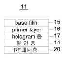
도 3a 내지 도 3c는 상기 홀로그램 패치(10)의 홀로그램층(17) 이면에 RF패턴층(20)이 형성되어 홀로그래픽 필름(11) 형태로 제작된 구성을 나타낸다.3A to 3C show a configuration in which the
상기와 같은 홀로그래픽 필름(11)은 홀로그램 패치(10)를 제작하기 위한 가장 기본적인 형태이며, 베이스 필름층(15), 레이어층(16), 홀로그램층(17)으로 형성됨은 주지된 것과 같다.The
상기 베이스 필름층(15)은 PET, OPP, PVC 수지필름으로 형성되어 홀로그램 패치(10)의 표면광택 및 보호기능을 수행하게 된다.The
상기 레이어층(16)은 엠보싱 처리되어 홀로그램의 입체형상 및 색상을 표현하기 위한 구성으로 엠보싱(요철)의 방식에 따라 소프트, 하드, UV엠보싱용으로 구분될 수 있다. 특히, 상기 레이어층(16)에는 염료를 첨가하여 원하는 색상을 얻을 수 있다.The
상기 홀로그램층(17)은 레이어층(16)에 의해 표면에 홀로그램의 입체형상이 표현되는 층이며, 레이어층(16)과의 사이에 금속박막층(18)이 형성되어 빛의 반사효과, 투명 금속박막에 따른 빛의 굴절효과를 얻을 수 있게 된다. 여기서, 상기 레이어층(16)과 홀로그램층(17)은 작업공정에 의해 적층순서가 바뀔 수 있다.The
상기 RF패턴층(20)은 홀로그램층(17)에 이후에 형성되는 것으로, 원실시예에서 전술한 것과 같이 홀로그램층(17)과의 사이에 절연을 위한 절연층(14)이 형성될 수 있으며, 홀로그램층(17)이 두꺼워 RF신호가 금속박막층(18)에 의해 간섭되지 않는다면 절연층(14)이 배재되고 홀로그램층(17) 면에 직접 형성될 수 있다.The
<제품 실시예2>≪ Example 2 >
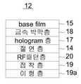
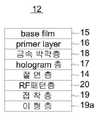
도 4a 및 도 4b는 상기 홀로그램 패치(10)의 홀로그램층(17) 이면에 RF패턴층(20)이 형성되고, 상기 RF패턴층(20)의 이면에 접착층(19)과 이형층(19a)이 형성되어 홀로그래픽 스티커 라벨(12) 형태로 제작된 구성을 나타낸다.4A and 4B show an
상기와 같은 홀로그래픽 스티커 라벨(12)은 결과적으로 대상물에 홀로그램 패치(10)를 가장 손쉽게 부착시키기 위한 스티커 형태의 제품이다.The
이를 위해 제품 실시예2의 홀로그래픽 스티커 라벨(12) 형태의 홀로그램은 베이스 필름층(15), 레이어층(16), 홀로그램층(17)으로 형성되며, 제품 실시예1에서와 같이 상기 금속박막층(18)과 절연층(14)이 선택적으로 형성된 구성에서 RF패턴층(20)이 형성되고, RF패턴층(20)에는 상기와 같이 접착층(19)과 이형층(19a)이 형성되어 구성된다.To this end, the hologram in the form of the
이때, 상기 베이스 필름층(15), 레이어층(16), 홀로그램층(17), 금속박막층(18), 절연층(14)은 제품 실시예1에서와 같다.At this time, the
<제품실시예3><Product Example 3>
도 5a 및 도 5b는 상기 홀로그램 패치(10)의 베이스 필름층(15)에 이형층(15a)이 형성되고, 홀로그램 패치(10)의 홀로그램층(17) 이면에 RF패턴층(20)과 RF패턴층(20)에 열압착을 수행하여 전사되기 위한 접착층(19)이 형성되어 홀로그래픽 스탬핑 포일(13) 형태로 제작된 구성을 나타낸다.5A and 5B are diagrams illustrating an example in which the
상기와 같은 홀로그래픽 스탬핑 포일(13)은 대상물(1)에 열압착되어 홀로그램 패치(10)가 전사되어 대상물(1)을 파괴하지 않는 한 대상물(1)과 분리되지 않도록 하기 위한 것이다.The
이를 위해 제품 실시예3의 홀로그래픽 스탬핑 포일(13) 형태의 홀로그램은 베이스 필름층(15)과 레이어층(16)의 사이에 이형층(15a)이 형성되고, 제품 실시예1, 제품실시예2에서와 같이 금속박막층(18)과 절연층(14)이 선택적으로 형성된 구성에서 상기와 같이 RF패턴층(20)과 접착층(19)이 형성되어 구성된다.To this end, the hologram in the form of the holographic stamping
이때, 상기 베이스 필름층(15), 레이어층(16), 홀로그램층(17), 금속박막층(18), 절연층(14)은 제품 실시예1, 제품 실시예2에서와 같다.The
도 6은 상기 홀로그램의 제작과정을 참고적으로 나타낸 순서도이다6 is a flow chart showing a procedure for manufacturing the hologram
도면을 참조하면, 상기와 같은 홀로그램 패치(10)를 제작하기 위해서는 제작하고자 하는 홀로그램 디자인을 제작(S1)함과 동시에 건판 상에 감광제 코팅을 수행하고,(S2) 노광 및 현상과정을 수행하는 마스터링 과정을 수행한 후,(S3) 금속박막층(18)을 형성하기 위한 전기도금과정을 수행하고,(S4) 홀로그램의 굴곡형태(3차원 형태)를 제작하는 엠보싱과정을 수행하게 된다.(S5) 여기서, 상기와 같은 홀로그램의 제작과정은 주지된 것은 것으로 이상의 기재를 생략한다.Referring to FIG. 1, in order to manufacture the
이후, 제품별 후공정을 수행(S6)하게 되는데, 상기 제품은 전술한 홀로그래픽 필름(11), 홀로그래픽 스티커 라벨(12), 홀로그래픽 스탬핑 포일(13) 형태이며, 상기 RF패턴층(20)이 형성된 홀로그램 패치(10)를 제작하기 위해 전술한 제품 실시예1 내지 제품 실시예3에서와 같은 구성으로 전도성 물질의 RF패턴층(20), 절연층(14), 이형층(15a, 19a), 접착층(19)을 진공증착 등의 과정에 의해 형성하게 된다.The product is in the form of a
도 7은 본 발명에 의한 시스템의 블록도, 도 8은 본 발명에 의한 시스템 중 고정형 RFID 리더기 블록도, 도 9는 본 발명에 의한 시스템 중 이동형 RFID 리더기 블록도이다.FIG. 7 is a block diagram of a system according to the present invention, FIG. 8 is a block diagram of a fixed type RFID reader in the system according to the present invention, and FIG. 9 is a block diagram of a mobile RFID reader in the system according to the present invention.
도면을 참조하면, 본 발명에 의한 시스템은 RF패턴층(20)을 갖는 홀로그램 패치(10), RFID 리더기(30), 통신망(60)으로 이루어진다. 여기서, 상기 홀로그램 패치(10)는 유가증권, 지폐, 여권, 상품권, 보안문서 등 지면으로 형성된 대상물(이하, 대상물)에 결합된다.Referring to the drawings, a system according to the present invention includes a
특히, 상기 홀로그램 패치(10)에 형성된 RF패턴층(20)에는 대상물의 정보 및 대상물의 복사를 방지하기 위한 장치의 제어정보 및 위조를 방지하기 위한 고유의 식별정보가 저장되어 구성된다. 이와 같은 홀로그램 패치(10)는 전술한 것과 같다.Particularly, the
상기 RFID 리더기(30)는 홀로그램 패치(10)에 형성된 RF패턴층(20)에서 발생된 RF신호를 리딩하여 대상물을 복사하기 위한 장치(3)의 구동을 제어하는 고정형 RFID 리더기(40)와, 상기 RF패턴층(20)에서 발생된 RF신호를 리딩하여 대상물의 진위여부를 판단하기 위해 유선 또는 무선의 단말기(4)에 설치된 이동형 RFID 리더기(50)로 구성된다.The
상기 고정형 RFID 리더기(40)는 리딩모듈(41), 제어모듈(42), 통신모듈(43)로 구성된다. 여기서, 상기 고정형 RFID 리더기(40)가 설치되기 위한 장치는 대상물의 복사를 시도하기 위한 복사기, 스캐너, 프린터, 카메라 등의 장치를 의미한다.The fixed
상기 리딩모듈(41)은 대상물에 결합된 RF패턴층(20)의 RF신호를 리딩하기 위한 구성이다. 이때, 상기 리딩모듈(41)은 RF패턴층(20)에서 발생되는 RF신호의 특정주파수를 인식하기 위한 것이다. 여기서, 상기 RF신호는 디지털 형태의 신호처리가 가능하도록 특정 데이터 형태로 코딩되어 출력된다.The
상기 제어모듈(42)은 전술된 복사를 시도하기 위한 장치(3)의 구동회로와 연동되도록 구성된다. 이와 같은 제어모듈(42)은 상기 리딩모듈(41)에서 리딩된 RF패턴층(20)의 RF신호를 전달받아 장치(3)의 구동을 제어하게 된다. 즉, 상기 제어모듈(42)은 리딩모듈(41)에서 전달받은 정보가 복사를 허용하지 않는 정보일 경우 이를 장치(3)의 제어회로에 전송하여 장치의 복사구동을 정지시키도록 하는 것이다.The
상기 통신모듈(43)은 리딩된 정보를 통신망(60)을 통해 인증서버(61)로 전송하고, 그에 따른 대응 정보를 수신하기 위한 구성이다. 여기서, 상기 인증서버(61)는 대상물에 대한 정보를 이미 데이터 베이스 상에 저장해 둔 장소가 되며, 이와 같은 인증서버(61)는 대상물이 화폐, 수표, 유가증권, 여권일 등일 경우, 국가 및 국가 산하기관 등의 공신력있는 기관의 서버가 되어야 하며, 대상물이 상품권, 보안용지 등일 경우, 상품권을 발행한 기업체 또는 그 기업체의 인증을 받은 별도의 인증업체 서버로 지정될 수도 있다.The
상기 이동형 RFID 리더기(50)는 상기 RF패턴층(20)의 RF신호를 리딩하여 대상물의 진위여부를 판단하기 위해 유선 또는 무선의 단말기(4)에 설치된 구성이다. 이와 같은 이동형 RFID 리더기(50)는 리딩모듈(51), 통신모듈(52), 표시모듈(53)로 구성된다.The
상기 리딩모듈(51)은 전술한 고정형 RFID 리더기(40)와 같이 대상물에 결합된 RF패턴층(20)의 RF신호의 특정주파수를 리딩하기 위한 구성이다. 여기서, 상기 RF신호는 디지털 형태의 신호처리가 가능하도록 특정 데이터 형태로 코딩되어 출력된다.The
상기 통신모듈(52)은 상기 리딩모듈(51)에서 리딩된 RF패턴층(20)의 RF신호를 전달받아 이를 통신망(60)을 통해 인증서버(61)로 전송하고, 그에 따른 대응 정보를 수신하기 위한 구성이다. 즉, 상기 인증서버(61)는 RF패턴층(20)에서 대상물(1)의 위조여부를 확인하기 위한 고유의 식별정보가 리딩되면, RFID 리더기(30)에서는 리딩된 정보를 인증서버(61)로 전송하게 되며, 상기 인증서버(61)에서는 해당 대상물의 정보를 이미 입력된 데이터 베이스의 데이터와 대비하여 해당 대상물의 위조여부를 판단한 후 이를 다시 RFID 리더기(30)로 전송하기 위한 구성이다.The
상기 표시모듈(53)은 인증서버(61)에서 전송된 정보를 시각적 또는 청각적으로 표시하기 위한 구성이다. 대표적으로 상기 표시모듈(53)은 LCD로 구현될 수 있으며, 이외에도 7-세그먼트 또는 위조여부가 확인됨에 따라 다른 색상의 빛을 발광하기 위한 LED, 부저, 스피커 등으로 적용될 수 있다.The
특히, 상기 이동식 RFID 리더기(30)는 통신모듈(52)과 표시모듈(53)이 이미 갖추어진 PC(노트북, 넷북이 대표적이며, 인터넷 라인이 연결된 구성을 의미함) 또는 휴대폰, PDA 등의 모바일기기에 리딩모듈(51)을 설치하여 구성될 수 있다.Particularly, the
이때, 상기 휴대폰, PDA 등의 모바일 기기에 적용된 이동식 RFID 리더기(30)를 구현하기 위해서는 전술한 인증서버(61)를 보유한 기관과 이동통신사 간의 계약을 수행하고, 보안에 대한 통신협약을 미리 설정함이 당연하다.At this time, in order to implement the
상기 통신망(60)은 고정형 및 이동형 RFID 리더기(50)와 전술한 인증서버(61)를 통신연결하기 위한 구성이다. 이와 같은 통신망(60)은 상기 고정형 및 이동형 RFID 리더기(50)와 인증서버(61)를 데이터 송수신이 가능하도록 연결시키기 위해 유선 또는 무선으로 구현되는 전용회선(LAN, WAN), 인터넷 통신망, 전화 통신망 중 1이상의 시스템을 선택하여 적용된다.The
도 10은 본 발명에 의한 시스템의 운영과정 순서도이다.FIG. 10 is a flowchart illustrating an operation procedure of the system according to the present invention.
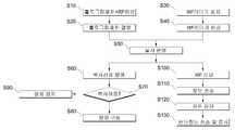
도면을 참조하면, 상기 복사 및 위조방지를 위한 시스템을 운영하기 위해서는 먼저 홀로그램 패치(10)에 RF패턴층(20)을 형성하여 제작하고,(S10) 제작된 RF패턴층(20)이 형성된 홀로그램 패치(10)를 대상물에 결합하게 된다.(S20)In order to operate the system for preventing copying and forgery, the
여기서, 상기 RF패턴층(20)에는 목적하는 대상물의 정보 및 복사가 가능한 장치(3)의 제어정보 및 위조를 방지하기 위한 고유의 식별정보가 기록된다.Here, in the
이후, 상기 RF패턴층(20)의 RF신호를 리딩하여 판독할 수 있는 고정형 또는 이동형 RFID 리더기(50)를 제공하게 되는데, 보다 구체적으로 상기 고정형 RFID 리더기(40)는 대상물의 복사를 수행하기 위한 장치에 내장되어 장치를 구동하기 위한 구동부와 연동시키도록 구성하고,(S30) 상기 이동형 RFID 리더기(50)는 위조를 확인하기 위해 대상물의 진위여부를 확인하기 위한 인증기관, 은행, 백화점, 마트, 편의점 등의 대상에 제공된다.(S40)Thereafter, a fixed or
이와 같이 고정형 및 이동형 RFID 리더기(50)의 제공이 완료되면, 본격적인 복사 및 위조방지를 위한 시스템이 본격적으로 실시되도록 운영된다.(S50)When the provision of the fixed and movable
이때, 상기 홀로그램 패치(10)가 부착된 대상물에 대해 복사를 수행하기 위한 장치의 신호가 입력되면,(S60) 장치에 설치된 고정형 RFID 리더기(40)는 RF패턴층(20)에 저장된 제어정보를 판독하게 된다.(S70) 여기서, 상기 정보가 복사를 허용하는 대상물에 대한 것일 경우 복사기 또는 스캐너가 정상적으로 구동될 수 있도록 하며,(S80) 상기 정보가 복사를 허용하지 않는 대상물에 대한 것이라면 고정형 RFID 리더기(40)는 장치의 구동부를 통해 장치가 구동을 정지하도록 하여 복사를 미연에 방지하게 된다.(S90)At this time, when a signal of a device for performing copying is input to the object to which the
또한, 상기 대상물에 대한 위조여부를 확인하기 위해서는 RF패턴층(20)을 갖는 홀로그램 패치(10)를 이동형 RFID 리더기(50)에 근접시키게 된다. 이때, 이동형 RFID 리더기(50)에서는 RF패턴층(20)에 기록된 대상물의 고유식별정보를 리딩하고,(S100) 리딩된 정보를 통신망(60)를 통해 인증서버(61)로 전송하게 된다.(S110)In order to check whether the object is falsified, the
이후, 상기 인증서버(61)에서는 이동형 RFID 리더기(50)를 통해 수신한 정보를 이미 입력된 데이터 베이스의 데이터와 대비하여 대상물의 진위여부를 판단하고,(S120) 판단된 결과를 이동형 RFID 리더기(50)로 전송하여 상기 판단된 내용을 표시모듈(53)에 표시하게 된다.(S130)In step S120, the
상기와 같은 과정에 의해 대상물의 복사방지 및 위조의 손쉬운 확인에 의한 위조방지를 유도할 수 있게 된다.According to the above-described process, it is possible to prevent the copying of the object and the forgery prevention by the easy confirmation of the forgery.
10: 홀로그램 패치 20: RF패턴층
30: RFID 리더기 40: 고정형 RFID 리더기
50: 이동형 RFID 리더기 60: 통신망10: Hologram patch 20: RF pattern layer
30: RFID reader 40: stationary RFID reader
50: mobile RFID reader 60: communication network
Claims (14)
Translated fromKorean대상물과 대향되는 증착필름 패치의 면에는 대상물의 정보, 대상물의 복사를 방지하기 위한 제어정보, 위조를 방지하기 위한 고유의 식별정보가 저장된 RF패턴층이 형성된 것을 특징으로 하는 RFID가 결합된 제품형 증착필름.A deposition film adhered to an object to prevent information recording, copying and forgery of the object,
Wherein an RF pattern layer storing information of an object, control information for preventing copying of the object, and unique identification information for preventing forgery is formed on the surface of the deposition film patch facing the object, Deposited film.
전도성 물질로 된 박막층이며, 특정의 RF신호를 발생시키기 위한 패턴으로 형성된 것을 특징으로 하는 RFID가 결합된 제품형 증착필름.The method of claim 1, wherein the RF pattern layer
Wherein the thin film layer is formed of a conductive material and is formed in a pattern for generating a specific RF signal.
RF신호를 발생시키기 위한 패턴이 단일의 물질로 형성된 것을 특징으로 하는 RFID가 결합된 제품형 증착필름.The method of claim 2, wherein the RF pattern layer
Wherein a pattern for generating an RF signal is formed of a single material.
RF신호를 발생시키기 위한 패턴이 2종이상의 물질이 복합적으로 형성된 것을 특징으로 하는 RFID가 결합된 제품형 증착필름.The method of claim 2, wherein the RF pattern layer
Wherein a pattern for generating an RF signal is composed of two or more materials in combination.
상기 증착필름 패치와 RF패턴층의 사이에는 증착필름 패치의 금속성분에 의한 RF패턴층의 RF신호 간섭을 차단하기 위한 절연층이 형성된 것을 특징으로 하는 RFID가 결합된 제품형 증착필름.The method according to claim 1,
Wherein an insulation layer is formed between the deposition film patch and the RF pattern layer to block RF signal interference of the RF pattern layer due to the metal component of the deposition film patch.
상기 증착필름 패치의 홀로그램층 이면에 RF패턴층과 RF패턴층에 열압착을 수행하여 전사되기 위한 접착층이 형성되어 필름 형태로 제작되는 것을 특징으로 하는 RFID가 결합된 제품형 증착필름.6. The method according to any one of claims 1 to 5,
Wherein the adhesive layer for transferring is formed by thermocompression bonding to the RF pattern layer and the RF pattern layer on the back surface of the hologram layer of the deposited film patch, and the film is formed in the form of a film.
상기 증착필름 패치의 홀로그램층 이면에 RF패턴층이 형성되고, 상기 RF패턴층의 이면에 접착층과 이형층이 형성되어 스티커 라벨 형태로 제작되는 것을 특징으로 하는 RFID가 결합된 제품형 증착필름.6. The method according to any one of claims 1 to 5,
Wherein the RF pattern layer is formed on the back surface of the hologram layer of the deposited film patch, and the adhesive layer and the release layer are formed on the back surface of the RF pattern layer to be formed in the form of a sticker label.
상기 증착필름 패치의 베이스 필름층에 이형층이 형성되고, 증착필름 패치의 홀로그램층 이면에 RF패턴층이 형성되어 스탬핑 포일 형태로 제작되는 것을 특징으로 하는 RFID가 결합된 제품형 증착필름.6. The method according to any one of claims 1 to 5,
Wherein a release layer is formed on the base film layer of the deposited film patch, and an RF pattern layer is formed on the rear surface of the holographic layer of the deposited film patch, and the film is formed in the form of a stamping foil.
상기 RF패턴층의 RF신호를 리딩하여 대상물을 복사하기 위한 장치의 구동을 제어하고, 상기 RF패턴층의 RF신호를 리딩하여 대상물의 진위여부를 판단하기 위한 RFID 리더기와;
상기 RFID 리더기에서 리딩한 정보에 대한 진위여부를 확인시키기 위해 인증서버를 구축하고, 상기 RFID 리더기와 인증서버를 데이터 송수신이 가능하도록 연결시키는 통신망;를 포함하는 것을 특징으로 하는 RFID가 결합된 제품형 증착필름을 이용한 보안시스템.A deposition film patch attached to a surface of an object including an RF pattern layer storing information of the object and control information of the apparatus for preventing copying of the object and unique identification information for preventing falsification;
An RFID reader for controlling driving of an apparatus for reading an RF signal of the RF pattern layer to copy an object and determining whether the object is authentic by reading an RF signal of the RF pattern layer;
And a communication network for establishing an authentication server to confirm authenticity of the information read by the RFID reader and connecting the RFID reader and the authentication server so that data can be transmitted and received, Security system using evaporated film.
상기 RF패턴층의 RF신호를 리딩하여 대상물을 복사하기 위한 장치의 구동을 제어하는 고정형 RFID 리더기와;
상기 RF패턴층의 RF신호를 리딩하여 대상물의 진위여부를 판단하기 위해 유선 또는 무선의 단말기에 설치된 이동형 RFID 리더기;를 포함하는 것을 특징으로 하는 RFID가 결합된 제품형 증착필름을 이용한 보안시스템.10. The method of claim 9, wherein the RFID reader
A fixed RFID reader for controlling driving of an apparatus for reading an RF signal of the RF pattern layer to copy an object;
And a mobile RFID reader installed in a wired or wireless terminal to read an RF signal of the RF pattern layer to determine authenticity of the object.
RF패턴층에서 발생된 RF신호를 리딩하는 리딩모듈과;
상기 장치의 구동회로와 연동되도록 구성되며, 상기 리딩모듈에서 리딩된 RF신호를 전달받아 장치의 구동을 제어하는 제어모듈과;
상기 리딩된 정보를 통신망을 통해 인증서버로 전송하고, 그에 따른 대응 정보를 수신하는 통신모듈;을 포함하는 것을 특징으로 하는 RFID가 결합된 제품형 증착필름을 이용한 보안시스템.The RFID reader of claim 10, wherein the fixed RFID reader
A reading module for reading the RF signal generated in the RF pattern layer;
A control module configured to be interlocked with the driving circuit of the apparatus, the control module receiving the RF signal read from the reading module and controlling driving of the apparatus;
And a communication module for transmitting the read information to an authentication server through a communication network and receiving corresponding information therefrom.
RF패턴층에서 발생된 RF신호를 리딩하는 리딩모듈과;
상기 리딩모듈에서 리딩된 RF신호를 전달받아 통신망을 통해 인증서버로 전송하고, 그에 따른 대응 정보를 수신하는 통신모듈과;
상기 인증서버에서 전송된 정보를 시각적 또는 청각적으로 표시하는 표시모듈;을 포함하는 것을 특징으로 하는 RFID가 결합된 제품형 증착필름을 이용한 보안시스템.11. The method of claim 10, wherein the mobile RFID reader
A reading module for reading the RF signal generated in the RF pattern layer;
A communication module for receiving the RF signal read by the reading module and transmitting the read RF signal to an authentication server through a communication network and receiving corresponding information;
And a display module for visually or audibly displaying the information transmitted from the authentication server. The security system using the product-type deposition film combined with RFID.
통신모듈과 표시모듈을 갖는 PC 또는 모바일기기에 리딩모듈을 설치하여 구성된 것을 특징으로 하는 RFID가 결합된 제품형 증착필름을 이용한 보안시스템.13. The method of claim 12, wherein the mobile RFID reader
And a reader module is installed on a PC or a mobile device having a communication module and a display module.
인터넷 통신망, 유선 또는 무선전화 통신망 중 1이상을 선택하여 적용하는 것을 특징으로 하는 RFID가 결합된 제품형 증착필름을 이용한 보안시스템.
14. The communication system according to any one of claims 9 to 13,
An Internet communication network, a wired or wireless telephone communication network is selected and applied to the security system.
Priority Applications (1)
| Application Number | Priority Date | Filing Date | Title |
|---|---|---|---|
| KR1020160054259AKR101704446B1 (en) | 2016-05-02 | 2016-05-02 | RFID combination type hologram |
Applications Claiming Priority (1)
| Application Number | Priority Date | Filing Date | Title |
|---|---|---|---|
| KR1020160054259AKR101704446B1 (en) | 2016-05-02 | 2016-05-02 | RFID combination type hologram |
Related Parent Applications (1)
| Application Number | Title | Priority Date | Filing Date |
|---|---|---|---|
| KR1020100139949ADivisionKR101704389B1 (en) | 2010-12-31 | 2010-12-31 | RFID combination type hologram and security system |
Publications (2)
| Publication Number | Publication Date |
|---|---|
| KR20160055762Atrue KR20160055762A (en) | 2016-05-18 |
| KR101704446B1 KR101704446B1 (en) | 2017-02-10 |
Family
ID=56113514
Family Applications (1)
| Application Number | Title | Priority Date | Filing Date |
|---|---|---|---|
| KR1020160054259AExpired - Fee RelatedKR101704446B1 (en) | 2016-05-02 | 2016-05-02 | RFID combination type hologram |
Country Status (1)
| Country | Link |
|---|---|
| KR (1) | KR101704446B1 (en) |
Citations (5)
| Publication number | Priority date | Publication date | Assignee | Title |
|---|---|---|---|---|
| JP2002366036A (en)* | 2001-06-07 | 2002-12-20 | Kurz Japan Kk | Sticker for recognizing vehicle |
| US20080308641A1 (en)* | 2007-04-10 | 2008-12-18 | Advanced Microelectronic And Automation Technology Ltd. | Smart card with switchable matching antenna |
| KR20090001738A (en)* | 2007-05-15 | 2009-01-09 | 주식회사 머큐리 | Security document copy management system |
| US20100063470A1 (en) | 1996-12-13 | 2010-03-11 | Migaku Suzuki | Highly absorbent composite and method of making the same |
| KR20100063470A (en)* | 2008-12-03 | 2010-06-11 | 삼성전자주식회사 | Chip-less rfid system using metamaterials and identification method thereof |
- 2016
- 2016-05-02KRKR1020160054259Apatent/KR101704446B1/ennot_activeExpired - Fee Related
Patent Citations (5)
| Publication number | Priority date | Publication date | Assignee | Title |
|---|---|---|---|---|
| US20100063470A1 (en) | 1996-12-13 | 2010-03-11 | Migaku Suzuki | Highly absorbent composite and method of making the same |
| JP2002366036A (en)* | 2001-06-07 | 2002-12-20 | Kurz Japan Kk | Sticker for recognizing vehicle |
| US20080308641A1 (en)* | 2007-04-10 | 2008-12-18 | Advanced Microelectronic And Automation Technology Ltd. | Smart card with switchable matching antenna |
| KR20090001738A (en)* | 2007-05-15 | 2009-01-09 | 주식회사 머큐리 | Security document copy management system |
| KR20100063470A (en)* | 2008-12-03 | 2010-06-11 | 삼성전자주식회사 | Chip-less rfid system using metamaterials and identification method thereof |
Also Published As
| Publication number | Publication date |
|---|---|
| KR101704446B1 (en) | 2017-02-10 |
Similar Documents
| Publication | Publication Date | Title |
|---|---|---|
| JP5151983B2 (en) | RFID information medium and article with the same | |
| JP4695327B2 (en) | Security paper and valuable documents created from it | |
| JP5128676B2 (en) | Non-contact IC labels and articles | |
| CA2338661A1 (en) | Security paper, method and device for checking the authenticity of documents recorded thereon | |
| CA2471415A1 (en) | Sheet material and apparatuses and methods for producing and processing such sheet material | |
| EP1179811A1 (en) | Security document and process for producing a security document | |
| JP2018512653A5 (en) | ||
| EP3549781B1 (en) | Hinged laminate body, booklet, and laminate body | |
| JP2011100181A (en) | Non-contact ic label, and adherend with built-in antenna | |
| KR101613595B1 (en) | coated film having RFID mixed with a patterns and security system using the same | |
| KR101704446B1 (en) | RFID combination type hologram | |
| KR101704389B1 (en) | RFID combination type hologram and security system | |
| JP2011090444A (en) | Non-contact ic label | |
| KR20120077847A (en) | Coated film and security system having printing type rfid | |
| JP2002055216A (en) | Optical change element and reading device therefor | |
| KR100781740B1 (en) | How to prevent counterfeiting of securities | |
| AU2012101699A4 (en) | Authenticable security element | |
| KR20150076370A (en) | Hologram Chipless RFID Tag and Method for Producing Hologram Chipless RFID Tag | |
| KR101704388B1 (en) | RFID Reading system for copy and forging prevention | |
| JP2011178148A (en) | System for managing non-contact ic label | |
| JP5206589B2 (en) | Non-contact IC label | |
| JP2011150409A (en) | Security document | |
| JP2006018475A (en) | IC card, tag or label with hologram printing or sticker | |
| JP2011164883A (en) | Contactless ic label, imaging apparatus and contactless ic label management system | |
| WO2018126398A1 (en) | Sticker combining rfid (radio frequency identification) with holographic label |
Legal Events
| Date | Code | Title | Description |
|---|---|---|---|
| A107 | Divisional application of patent | ||
| A201 | Request for examination | ||
| PA0107 | Divisional application | St.27 status event code:A-0-1-A10-A16-div-PA0107 St.27 status event code:A-0-1-A10-A18-div-PA0107 | |
| PA0201 | Request for examination | St.27 status event code:A-1-2-D10-D11-exm-PA0201 | |
| PG1501 | Laying open of application | St.27 status event code:A-1-1-Q10-Q12-nap-PG1501 | |
| E902 | Notification of reason for refusal | ||
| PE0902 | Notice of grounds for rejection | St.27 status event code:A-1-2-D10-D21-exm-PE0902 | |
| E13-X000 | Pre-grant limitation requested | St.27 status event code:A-2-3-E10-E13-lim-X000 | |
| P11-X000 | Amendment of application requested | St.27 status event code:A-2-2-P10-P11-nap-X000 | |
| P13-X000 | Application amended | St.27 status event code:A-2-2-P10-P13-nap-X000 | |
| E90F | Notification of reason for final refusal | ||
| PE0902 | Notice of grounds for rejection | St.27 status event code:A-1-2-D10-D21-exm-PE0902 | |
| P11-X000 | Amendment of application requested | St.27 status event code:A-2-2-P10-P11-nap-X000 | |
| P13-X000 | Application amended | St.27 status event code:A-2-2-P10-P13-nap-X000 | |
| E701 | Decision to grant or registration of patent right | ||
| PE0701 | Decision of registration | St.27 status event code:A-1-2-D10-D22-exm-PE0701 | |
| GRNT | Written decision to grant | ||
| PR0701 | Registration of establishment | St.27 status event code:A-2-4-F10-F11-exm-PR0701 | |
| PR1002 | Payment of registration fee | Fee payment year number:1 St.27 status event code:A-2-2-U10-U11-oth-PR1002 | |
| R18-X000 | Changes to party contact information recorded | St.27 status event code:A-5-5-R10-R18-oth-X000 | |
| PG1601 | Publication of registration | St.27 status event code:A-4-4-Q10-Q13-nap-PG1601 | |
| PN2301 | Change of applicant | St.27 status event code:A-5-5-R10-R11-asn-PN2301 | |
| PN2301 | Change of applicant | St.27 status event code:A-5-5-R10-R14-asn-PN2301 | |
| P14-X000 | Amendment of ip right document requested | St.27 status event code:A-5-5-P10-P14-nap-X000 | |
| P16-X000 | Ip right document amended | St.27 status event code:A-5-5-P10-P16-nap-X000 | |
| Q16-X000 | A copy of ip right certificate issued | St.27 status event code:A-4-4-Q10-Q16-nap-X000 | |
| FPAY | Annual fee payment | Payment date:20200203 Year of fee payment:4 | |
| PR1001 | Payment of annual fee | Fee payment year number:4 St.27 status event code:A-4-4-U10-U11-oth-PR1001 | |
| PC1903 | Unpaid annual fee | Not in force date:20210203 Payment event data comment text:Termination Category : DEFAULT_OF_REGISTRATION_FEE St.27 status event code:A-4-4-U10-U13-oth-PC1903 | |
| PC1903 | Unpaid annual fee | Ip right cessation event data comment text:Termination Category : DEFAULT_OF_REGISTRATION_FEE Not in force date:20210203 St.27 status event code:N-4-6-H10-H13-oth-PC1903 |