KR20160053051A - Loading effect control unit and organic light emitting display device having the same - Google Patents
Loading effect control unit and organic light emitting display device having the sameDownload PDFInfo
- Publication number
- KR20160053051A KR20160053051AKR1020140149338AKR20140149338AKR20160053051AKR 20160053051 AKR20160053051 AKR 20160053051AKR 1020140149338 AKR1020140149338 AKR 1020140149338AKR 20140149338 AKR20140149338 AKR 20140149338AKR 20160053051 AKR20160053051 AKR 20160053051A
- Authority
- KR
- South Korea
- Prior art keywords
- voltage
- power supply
- loading effect
- display panel
- reference voltage
- Prior art date
- Legal status (The legal status is an assumption and is not a legal conclusion. Google has not performed a legal analysis and makes no representation as to the accuracy of the status listed.)
- Granted
Links
- 230000000694effectsEffects0.000titleclaimsabstractdescription106
- 238000001514detection methodMethods0.000claimsabstractdescription69
- 238000000034methodMethods0.000claims1
- 238000010586diagramMethods0.000description16
- 239000000470constituentSubstances0.000description2
- 230000004044responseEffects0.000description2
- 238000004891communicationMethods0.000description1
- 239000004973liquid crystal related substanceSubstances0.000description1
- 238000012986modificationMethods0.000description1
- 230000004048modificationEffects0.000description1
- 230000002093peripheral effectEffects0.000description1
- 229920000642polymerPolymers0.000description1
- 239000007787solidSubstances0.000description1
- 230000003068static effectEffects0.000description1
Images


Classifications
- G—PHYSICS
- G09—EDUCATION; CRYPTOGRAPHY; DISPLAY; ADVERTISING; SEALS
- G09G—ARRANGEMENTS OR CIRCUITS FOR CONTROL OF INDICATING DEVICES USING STATIC MEANS TO PRESENT VARIABLE INFORMATION
- G09G3/00—Control arrangements or circuits, of interest only in connection with visual indicators other than cathode-ray tubes
- G09G3/20—Control arrangements or circuits, of interest only in connection with visual indicators other than cathode-ray tubes for presentation of an assembly of a number of characters, e.g. a page, by composing the assembly by combination of individual elements arranged in a matrix no fixed position being assigned to or needed to be assigned to the individual characters or partial characters
- G09G3/2003—Display of colours
- G—PHYSICS
- G09—EDUCATION; CRYPTOGRAPHY; DISPLAY; ADVERTISING; SEALS
- G09G—ARRANGEMENTS OR CIRCUITS FOR CONTROL OF INDICATING DEVICES USING STATIC MEANS TO PRESENT VARIABLE INFORMATION
- G09G3/00—Control arrangements or circuits, of interest only in connection with visual indicators other than cathode-ray tubes
- G09G3/20—Control arrangements or circuits, of interest only in connection with visual indicators other than cathode-ray tubes for presentation of an assembly of a number of characters, e.g. a page, by composing the assembly by combination of individual elements arranged in a matrix no fixed position being assigned to or needed to be assigned to the individual characters or partial characters
- G09G3/22—Control arrangements or circuits, of interest only in connection with visual indicators other than cathode-ray tubes for presentation of an assembly of a number of characters, e.g. a page, by composing the assembly by combination of individual elements arranged in a matrix no fixed position being assigned to or needed to be assigned to the individual characters or partial characters using controlled light sources
- G09G3/30—Control arrangements or circuits, of interest only in connection with visual indicators other than cathode-ray tubes for presentation of an assembly of a number of characters, e.g. a page, by composing the assembly by combination of individual elements arranged in a matrix no fixed position being assigned to or needed to be assigned to the individual characters or partial characters using controlled light sources using electroluminescent panels
- G09G3/32—Control arrangements or circuits, of interest only in connection with visual indicators other than cathode-ray tubes for presentation of an assembly of a number of characters, e.g. a page, by composing the assembly by combination of individual elements arranged in a matrix no fixed position being assigned to or needed to be assigned to the individual characters or partial characters using controlled light sources using electroluminescent panels semiconductive, e.g. using light-emitting diodes [LED]
- G09G3/3208—Control arrangements or circuits, of interest only in connection with visual indicators other than cathode-ray tubes for presentation of an assembly of a number of characters, e.g. a page, by composing the assembly by combination of individual elements arranged in a matrix no fixed position being assigned to or needed to be assigned to the individual characters or partial characters using controlled light sources using electroluminescent panels semiconductive, e.g. using light-emitting diodes [LED] organic, e.g. using organic light-emitting diodes [OLED]
- G09G3/3266—Details of drivers for scan electrodes
- G—PHYSICS
- G09—EDUCATION; CRYPTOGRAPHY; DISPLAY; ADVERTISING; SEALS
- G09G—ARRANGEMENTS OR CIRCUITS FOR CONTROL OF INDICATING DEVICES USING STATIC MEANS TO PRESENT VARIABLE INFORMATION
- G09G3/00—Control arrangements or circuits, of interest only in connection with visual indicators other than cathode-ray tubes
- G09G3/20—Control arrangements or circuits, of interest only in connection with visual indicators other than cathode-ray tubes for presentation of an assembly of a number of characters, e.g. a page, by composing the assembly by combination of individual elements arranged in a matrix no fixed position being assigned to or needed to be assigned to the individual characters or partial characters
- G09G3/22—Control arrangements or circuits, of interest only in connection with visual indicators other than cathode-ray tubes for presentation of an assembly of a number of characters, e.g. a page, by composing the assembly by combination of individual elements arranged in a matrix no fixed position being assigned to or needed to be assigned to the individual characters or partial characters using controlled light sources
- G09G3/30—Control arrangements or circuits, of interest only in connection with visual indicators other than cathode-ray tubes for presentation of an assembly of a number of characters, e.g. a page, by composing the assembly by combination of individual elements arranged in a matrix no fixed position being assigned to or needed to be assigned to the individual characters or partial characters using controlled light sources using electroluminescent panels
- G09G3/32—Control arrangements or circuits, of interest only in connection with visual indicators other than cathode-ray tubes for presentation of an assembly of a number of characters, e.g. a page, by composing the assembly by combination of individual elements arranged in a matrix no fixed position being assigned to or needed to be assigned to the individual characters or partial characters using controlled light sources using electroluminescent panels semiconductive, e.g. using light-emitting diodes [LED]
- G09G3/3208—Control arrangements or circuits, of interest only in connection with visual indicators other than cathode-ray tubes for presentation of an assembly of a number of characters, e.g. a page, by composing the assembly by combination of individual elements arranged in a matrix no fixed position being assigned to or needed to be assigned to the individual characters or partial characters using controlled light sources using electroluminescent panels semiconductive, e.g. using light-emitting diodes [LED] organic, e.g. using organic light-emitting diodes [OLED]
- G09G3/3275—Details of drivers for data electrodes
- G09G3/3291—Details of drivers for data electrodes in which the data driver supplies a variable data voltage for setting the current through, or the voltage across, the light-emitting elements
- G—PHYSICS
- G09—EDUCATION; CRYPTOGRAPHY; DISPLAY; ADVERTISING; SEALS
- G09G—ARRANGEMENTS OR CIRCUITS FOR CONTROL OF INDICATING DEVICES USING STATIC MEANS TO PRESENT VARIABLE INFORMATION
- G09G3/00—Control arrangements or circuits, of interest only in connection with visual indicators other than cathode-ray tubes
- G09G3/20—Control arrangements or circuits, of interest only in connection with visual indicators other than cathode-ray tubes for presentation of an assembly of a number of characters, e.g. a page, by composing the assembly by combination of individual elements arranged in a matrix no fixed position being assigned to or needed to be assigned to the individual characters or partial characters
- G09G3/34—Control arrangements or circuits, of interest only in connection with visual indicators other than cathode-ray tubes for presentation of an assembly of a number of characters, e.g. a page, by composing the assembly by combination of individual elements arranged in a matrix no fixed position being assigned to or needed to be assigned to the individual characters or partial characters by control of light from an independent source
- G09G3/36—Control arrangements or circuits, of interest only in connection with visual indicators other than cathode-ray tubes for presentation of an assembly of a number of characters, e.g. a page, by composing the assembly by combination of individual elements arranged in a matrix no fixed position being assigned to or needed to be assigned to the individual characters or partial characters by control of light from an independent source using liquid crystals
- G09G3/3611—Control of matrices with row and column drivers
- G09G3/3696—Generation of voltages supplied to electrode drivers
- G—PHYSICS
- G09—EDUCATION; CRYPTOGRAPHY; DISPLAY; ADVERTISING; SEALS
- G09G—ARRANGEMENTS OR CIRCUITS FOR CONTROL OF INDICATING DEVICES USING STATIC MEANS TO PRESENT VARIABLE INFORMATION
- G09G2300/00—Aspects of the constitution of display devices
- G09G2300/04—Structural and physical details of display devices
- G09G2300/0421—Structural details of the set of electrodes
- G09G2300/0426—Layout of electrodes and connections
- G—PHYSICS
- G09—EDUCATION; CRYPTOGRAPHY; DISPLAY; ADVERTISING; SEALS
- G09G—ARRANGEMENTS OR CIRCUITS FOR CONTROL OF INDICATING DEVICES USING STATIC MEANS TO PRESENT VARIABLE INFORMATION
- G09G2320/00—Control of display operating conditions
- G09G2320/02—Improving the quality of display appearance
- G09G2320/0233—Improving the luminance or brightness uniformity across the screen
- G—PHYSICS
- G09—EDUCATION; CRYPTOGRAPHY; DISPLAY; ADVERTISING; SEALS
- G09G—ARRANGEMENTS OR CIRCUITS FOR CONTROL OF INDICATING DEVICES USING STATIC MEANS TO PRESENT VARIABLE INFORMATION
- G09G2320/00—Control of display operating conditions
- G09G2320/02—Improving the quality of display appearance
- G09G2320/0242—Compensation of deficiencies in the appearance of colours
- G—PHYSICS
- G09—EDUCATION; CRYPTOGRAPHY; DISPLAY; ADVERTISING; SEALS
- G09G—ARRANGEMENTS OR CIRCUITS FOR CONTROL OF INDICATING DEVICES USING STATIC MEANS TO PRESENT VARIABLE INFORMATION
- G09G2320/00—Control of display operating conditions
- G09G2320/02—Improving the quality of display appearance
- G09G2320/0271—Adjustment of the gradation levels within the range of the gradation scale, e.g. by redistribution or clipping
- G09G2320/0276—Adjustment of the gradation levels within the range of the gradation scale, e.g. by redistribution or clipping for the purpose of adaptation to the characteristics of a display device, i.e. gamma correction
- G—PHYSICS
- G09—EDUCATION; CRYPTOGRAPHY; DISPLAY; ADVERTISING; SEALS
- G09G—ARRANGEMENTS OR CIRCUITS FOR CONTROL OF INDICATING DEVICES USING STATIC MEANS TO PRESENT VARIABLE INFORMATION
- G09G2330/00—Aspects of power supply; Aspects of display protection and defect management
- G09G2330/02—Details of power systems and of start or stop of display operation
- G09G2330/028—Generation of voltages supplied to electrode drivers in a matrix display other than LCD
Landscapes
- Engineering & Computer Science (AREA)
- Physics & Mathematics (AREA)
- Computer Hardware Design (AREA)
- General Physics & Mathematics (AREA)
- Theoretical Computer Science (AREA)
- Chemical & Material Sciences (AREA)
- Crystallography & Structural Chemistry (AREA)
- Control Of Indicators Other Than Cathode Ray Tubes (AREA)
- Control Of El Displays (AREA)
Abstract
Translated fromKoreanDescription
Translated fromKorean본 발명은 로딩 이펙트 제어 장치에 관한 것이다. 보다 상세하게는, 본 발명은 로딩 이펙트 제어 장치 및 이를 포함하는 유기 발광 표시 장치에 관한 것이다.The present invention relates to a loading effect control device. More particularly, the present invention relates to a loading effect control device and an organic light emitting display including the same.
최근, 음극선관(Cathode Ray Tube)의 단점인 무게와 부피를 줄일 수 있는 각종 평판 표시 장치들이 개발되고 있다. 평판 표시 장치로는 액정 표시 장치(Liquid Crystal Display; LCD), 전계 방출 표시 장치(Field Emission Display; FED), 플라즈마 표시 패널(Plasma Display Panel; PDP) 및 유기 발광 표시 장치(Organic Light Emitting Display; OLED) 등이 있다. 특히, 유기 발광 표시 장치는 넓은 시야각, 빠른 응답 속도, 얇은 두께, 낮은 소비 전력 등의 여러 가지 장점들을 가지기 때문에 유망한 차세대 표시 장치로 각광받고 있다.2. Description of the Related Art Recently, various flat panel display devices capable of reducing weight and volume, which are disadvantages of cathode ray tubes (CRTs), have been developed. Examples of flat panel display devices include a liquid crystal display (LCD), a field emission display (FED), a plasma display panel (PDP), and an organic light emitting display (OLED) ). In particular, organic light emitting display devices are attracting attention as promising next generation display devices because they have various advantages such as wide viewing angle, fast response speed, thin thickness and low power consumption.
유기 발광 표시 장치의 구동 시 전원 공급 배선의 저항 등에 의해 전압 강하가 발생할 수 있다. 이 때, 표시 패널에 표시되는 이미지에 따라 전압 강하량이 변경되는 로딩 이펙트(loading effect)가 발생하여 감마 전압이 변경될 수 있다.A voltage drop may occur due to the resistance of the power supply wiring when the OLED display is driven. At this time, a loading effect occurs in which the voltage drop amount is changed according to the image displayed on the display panel, and the gamma voltage may be changed.
본 발명의 일 목적은 로딩 이펙트를 제어하는 로딩 이펙트 제어 장치를 제공하는 것이다.It is an object of the present invention to provide a loading effect control device for controlling a loading effect.
본 발명의 다른 목적은 상기 로딩 이펙트 제어 장치를 포함하는 유기 발광 표시 장치를 제공하는 것이다.It is another object of the present invention to provide an organic light emitting display device including the loading effect control device.
그러나, 본 발명이 목적은 상술한 목적으로 한정되는 것은 아니며, 본 발명의 사상 및 영역으로부터 벗어나지 않는 범위에서 다양하게 확장될 수 있을 것이다.However, the object of the present invention is not limited to the above-described objects, and various modifications may be made without departing from the spirit and scope of the present invention.
본 발명의 일 목적을 달성하기 위하여, 본 발명의 실시예들에 따른 로딩 이펙트 제어 장치는 제1 전원 전압이 인가되는 제 1 전원 전압 공급 배선과 표시 패널 내에서 연결되는 검출 배선, 상기 검출 배선을 통해 상기 표시 패널 내에서의 상기 제 1 전원 전압을 측정하고, 상기 제 1 전원 전압과 기 설정된 제 1 기준 전압을 비교하여 상기 표시 패널의 로드량에 상응하는 제 1 전압으로 출력하는 검출부, 상기 검출된 로드량 및 로딩 이펙트 설정에 따라 로드 조절량을 결정하고, 상기 결정된 로드 조절량에 상응하는 제 2 전압을 출력하는 로드 조절부 및 상기 결정된 로드 조절량에 따라 감마 기준 전압을 조절하는 감마 기준 전압 생성부를 포함할 수 있다.In order to accomplish one object of the present invention, a loading effect controller according to embodiments of the present invention includes a first power supply voltage supply line to which a first power voltage is applied, a detection line connected in the display panel, A detection unit for measuring the first power supply voltage in the display panel, comparing the first power supply voltage with a predetermined first reference voltage and outputting the first power supply voltage as a first voltage corresponding to a load amount of the display panel, And a gamma reference voltage generator for adjusting a gamma reference voltage according to the determined load adjustment amount. The gamma reference voltage generator includes a gamma reference voltage generator for determining a load adjustment amount according to the load amount and the loading effect setting, and outputting a second voltage corresponding to the determined load adjustment amount, can do.
일 실시예에 의하면, 상기 검출부는 상기 제 1 전원 전압 공급 배선에서 전압 강하가 발생된 후의 상기 제 1 전원 전압을 측정할 수 있다.According to an embodiment, the detection unit may measure the first power supply voltage after a voltage drop has occurred in the first power supply voltage supply line.
일 실시예에 의하면, 상기 검출부는 상기 제 1 전원 전압과 상기 제 1 기준 전압의 차를 상기 제 1 전압으로 출력하는 비교기를 포함할 수 있다.According to an embodiment, the detecting unit may include a comparator that outputs a difference between the first power supply voltage and the first reference voltage to the first voltage.
일 실시예에 의하면, 상기 제 1 기준 전압은, 상기 표시 패널에서 백색 영상이 표시될 때, 상기 검출 배선을 통해서 측정되는 상기 제 1 전원 전압일 수 있다.According to an embodiment, the first reference voltage may be the first power supply voltage measured through the detection wiring when a white image is displayed on the display panel.
일 실시예에 의하면, 상기 로드 조절부는 상기 로드량 및 상기 로딩 이펙트 설정에 따라 상기 로드 조절량의 크기를 결정하는 제 1 디코더 및 상기 로딩 이펙트 설정에 따라 상기 로드 조절량의 극성을 결정하는 제 2 디코더를 포함할 수 있다.According to an embodiment, the load control unit may include a first decoder for determining the magnitude of the load adjustment amount according to the load amount and the loading effect setting, and a second decoder for determining the polarity of the load adjustment amount according to the loading effect setting .
일 실시예에 의하면, 상기 제 1 디코더는 상기 제 1 전압이 일정 비율로 분압된 분압 전압들을 생성하고, 상기 로딩 이펙트 설정에 따라 상기 분압 전압들 중 하나를 선택하여 제 3 전압으로 출력할 수 있다.According to an embodiment of the present invention, the first decoder generates divided voltages in which the first voltage is divided by a predetermined ratio, and selects one of the divided voltages in accordance with the loading effect, and outputs the selected voltage as a third voltage .
일 실시예에 의하면, 상기 제 2 디코더는 상기 제 3 전압의 극성을 반전시키는 인버터 및 상기 제 3 전압의 극성을 유지시키는 버퍼를 포함할 수 있다.According to an embodiment, the second decoder may include an inverter for inverting the polarity of the third voltage and a buffer for maintaining the polarity of the third voltage.
일 실시예에 의하면, 상기 제 1 디코더는 상기 인버터 또는 상기 버퍼와 선택적으로 연결될 수 있다.According to one embodiment, the first decoder may be selectively connected to the inverter or the buffer.
일 실시예에 의하면, 상기 감마 기준 전압 생성부는 기 설정된 제 2 기준 전압에 상기 로드 조절량에 상응하는 상기 제 2 전압을 더하는 연산 증폭기를 포함할 수 있다.According to an embodiment, the gamma reference voltage generator may include an operational amplifier that adds the second voltage corresponding to the load adjustment amount to a predetermined second reference voltage.
본 발명의 다른 목적을 달성하기 위하여, 본 발명의 실시예들에 따른 유기 발광 표시 장치는 복수의 화소들을 포함하는 표시 패널, 상기 표시 패널에 제 1 전원 전압 및 제 2 전원 전압을 공급하는 전원 공급부, 상기 표시 패널에서 검출되는 상기 제 1 전원 전압과 기 설정된 제 1 기준 전압의 차를 상기 표시 패널의 로드량으로 산출하고, 상기 산출된 로드량 및 로딩 이펙트 설정에 따라 로드 조절량을 결정하며, 상기 결정된 로드 조절량에 따라 감마 기준 전압을 조절하는 로딩 이펙트 제어부, 상기 표시 패널에 데이터 신호를 공급하는 데이터 구동부, 상기 표시 패널에 스캔 신호를 공급하는 스캔 구동부 및 상기 데이터 구동부 및 상기 스캔 구동부를 제어하는 제어 신호를 생성하는 타이밍 제어부를 포함할 수 있다.According to another aspect of the present invention, there is provided an OLED display including a display panel including a plurality of pixels, a power supply unit supplying a first power voltage and a second power voltage to the display panel, , Calculating a difference between the first power supply voltage detected by the display panel and a predetermined first reference voltage as a load amount of the display panel and determining a load adjustment amount according to the calculated load amount and the loading effect setting, A data driver for supplying a data signal to the display panel, a scan driver for supplying a scan signal to the display panel, and a controller for controlling the data driver and the scan driver, And a timing controller for generating a signal.
일 실시예에 의하면, 상기 로딩 이펙트 제어부는 상기 제 1 전원 전압이 인가되는 제 1 전원 전압 공급 배선과 상기 표시 패널 내에서 연결되는 검출 배선, 상기 검출 배선을 통해 상기 표시 패널 내에서의 상기 제 1 전원 전압을 측정하고, 상기 제 1 전원 전압과 기 설정된 제 1 기준 전압을 비교하여 상기 표시 패널의 로드량에 상응하는 제 1 전압으로 출력하는 검출부, 상기 검출된 로드량 및 로딩 이펙트 설정에 따라 로드 조절량을 결정하고, 상기 결정된 로드 조절량에 상응하는 제 2 전압을 출력하는 로드 조절부 및 상기 결정된 로드 조절량에 따라 감마 기준 전압을 조절하는 감마 기준 전압 생성부를 포함할 수 있다.According to an embodiment, the loading effect control unit may include a first power supply voltage supply line to which the first power voltage is applied and a detection line connected in the display panel, A detecting unit for measuring a power supply voltage and comparing the first power supply voltage with a predetermined first reference voltage and outputting the first voltage as a first voltage corresponding to a load amount of the display panel; And a gamma reference voltage generator configured to adjust a gamma reference voltage according to the determined load adjustment amount. The gamma reference voltage generator may further include a gamma reference voltage generator configured to adjust a gamma reference voltage according to the determined load adjustment amount.
일 실시예에 의하면, 상기 검출부는 상기 제 1 전원 전압 공급 배선에서 전압 강하가 발생된 후의 상기 제 1 전원 전압을 측정할 수 있다.According to an embodiment, the detection unit may measure the first power supply voltage after a voltage drop has occurred in the first power supply voltage supply line.
일 실시예에 의하면, 상기 검출부는 상기 제 1 전원 전압과 상기 제 1 기준 전압의 차를 상기 제 1 전압으로 출력하는 비교기를 포함할 수 있다.According to an embodiment, the detecting unit may include a comparator that outputs a difference between the first power supply voltage and the first reference voltage to the first voltage.
일 실시예에 의하면, 상기 제 1 기준 전압은, 상기 표시 패널에서 백색 영상이 표시될 때, 상기 검출 배선을 통해서 측정되는 상기 제 1 전원 전압일 수 있다.According to an embodiment, the first reference voltage may be the first power supply voltage measured through the detection wiring when a white image is displayed on the display panel.
일 실시예에 의하면, 상기 로드 조절부는 상기 로드량 및 상기 로딩 이펙트 설정에 따라 상기 로드 조절량의 크기를 결정하는 제 1 디코더 및 상기 로딩 이펙트 설정에 따라 상기 로드 조절량의 극성을 결정하는 제 2 디코더를 포함할 수 있다.According to an embodiment, the load control unit may include a first decoder for determining the magnitude of the load adjustment amount according to the load amount and the loading effect setting, and a second decoder for determining the polarity of the load adjustment amount according to the loading effect setting .
일 실시예에 의하면, 상기 제 1 디코더는 상기 제 1 전압이 일정 비율로 분압된 분압 전압들을 생성하고, 상기 로딩 이펙트 설정에 따라 상기 분압 전압들 중 하나를 선택하여 제 3 전압으로 출력할 수 있다.According to an embodiment of the present invention, the first decoder generates divided voltages in which the first voltage is divided by a predetermined ratio, and selects one of the divided voltages in accordance with the loading effect, and outputs the selected voltage as a third voltage .
일 실시예에 의하면, 상기 제 2 디코더는 상기 제 3 전압의 극성을 반전시키는 인버터 및 상기 제 3 전압의 극성을 유지시키는 버퍼를 포함할 수 있다.According to an embodiment, the second decoder may include an inverter for inverting the polarity of the third voltage and a buffer for maintaining the polarity of the third voltage.
일 실시예에 의하면, 상기 제 1 디코더는 상기 인버터 또는 상기 버퍼와 선택적으로 연결될 수 있다.According to one embodiment, the first decoder may be selectively connected to the inverter or the buffer.
일 실시예에 의하면, 상기 감마 기준 전압 생성부는 기 설정된 제 2 기준 전압에 상기 로드 조절량에 상응하는 상기 제 2 전압을 더하는 연산 증폭기를 포함할 수 있다.According to an embodiment, the gamma reference voltage generator may include an operational amplifier that adds the second voltage corresponding to the load adjustment amount to a predetermined second reference voltage.
일 실시예에 의하면, 상기 로딩 이펙트 제어부는 상기 타이밍 제어부 내부에 구비되거나 상기 타이밍 제어부와 연결될 수 있다.According to an embodiment, the loading effect control unit may be provided inside the timing control unit or may be connected to the timing control unit.
본 발명의 실시예들에 따른 로딩 이펙트 제어 장치 및 유기 발광 표시 장치는 표시 패널의 로드량을 산출하고, 상기 로드량 및 로딩 이펙트 설정에 따라 로드 조절량을 결정함으로써, 감마 기준 전압을 조절할 수 있다. 따라서, 표시 패널의 색 정확도 또는 시인성을 향상시킬 수 있다.The loading effect controller and the organic light emitting display according to embodiments of the present invention can adjust the gamma reference voltage by calculating the load amount of the display panel and determining the load adjustment amount according to the load amount and the loading effect setting. Therefore, the color accuracy or visibility of the display panel can be improved.
다만, 본 발명의 효과는 상술한 효과로 한정되는 것이 아니며, 본 발명의 사상 및 영역으로부터 벗어나지 않는 범위에서 다양하게 확장될 수 있을 것이다.However, the effects of the present invention are not limited to the above-described effects, and may be variously extended without departing from the spirit and scope of the present invention.
도 1은 본 발명의 실시예들에 따른 로딩 이펙트 제어 장치를 나타내는 블록도이다.
도 2는 도 1의 로딩 이펙트 제어 장치에 포함되는 검출 배선 및 검출부를 나타내는 도면이다.
도 3은 도 1의 로딩 이펙트 제어 장치에 포함되는 검출부를 나타내는 회로도이다.
도 4는 도 1의 로딩 이펙트 제어 장치에 포함되는 로드 조절부를 나타내는 회로도이다.
도 5는 도 4의 로드 조절부에 포함되는 제 1 디코더를 나타내는 회로도이다.
도 6a 및 도 6b는 도 4의 로드 조절부에 포함되는 제 2 디코더를 나타내는 회로도들이다.
도 7은 도 1의 로딩 이펙트 제어 장치에 포함되는 감마 기준 전압 생성부를 나타내는 회로도이다.
도 8은 본 발명의 실시예들에 따른 유기 발광 표시 장치를 나타내는 블록도이다.
도 9는 도 8의 유기 발광 표시 장치를 포함하는 전자 기기를 나타내는 도면이다.
도 10은 도 9의 전자 기기가 스마트폰으로 구현되는 일 예를 나타내는 도면이다.1 is a block diagram illustrating a loading effect control apparatus according to embodiments of the present invention.
Fig. 2 is a view showing a detection wiring and a detection part included in the loading effect control device of Fig. 1. Fig.
3 is a circuit diagram showing a detection unit included in the loading effect control device of FIG.
4 is a circuit diagram showing a load control unit included in the loading effect control apparatus of FIG.
FIG. 5 is a circuit diagram showing a first decoder included in the load control unit of FIG. 4; FIG.
6A and 6B are circuit diagrams illustrating a second decoder included in the load adjustment unit of FIG.
7 is a circuit diagram showing a gamma reference voltage generator included in the loading effect controller of FIG.
8 is a block diagram illustrating an organic light emitting display according to embodiments of the present invention.
9 is a view showing an electronic apparatus including the organic light emitting diode display of FIG.
10 is a diagram showing an example in which the electronic device of FIG. 9 is implemented as a smartphone.
이하, 첨부한 도면들을 참조하여, 본 발명의 바람직한 실시예를 보다 상세하게 설명하고자 한다. 도면상의 동일한 구성요소에 대해서는 동일한 참조부호를 사용하고 동일한 구성요소에 대해서 중복된 설명은 생략한다.Hereinafter, preferred embodiments of the present invention will be described in detail with reference to the accompanying drawings. The same reference numerals are used for the same constituent elements in the drawings and redundant explanations for the same constituent elements are omitted.
도 1은 본 발명의 실시예들에 따른 로딩 이펙트 제어 장치를 나타내는 블록도이고, 도 2는 도 1의 로딩 이펙트 제어 장치에 포함되는 검출 배선 및 검출부를 나타내는 도면이다.FIG. 1 is a block diagram showing a loading effect control device according to an embodiment of the present invention, and FIG. 2 is a diagram showing a detection wiring and a detection part included in the loading effect control device of FIG.
일반적으로 유기 발광 표시 장치에는 표시 패널(130)에 표시되는 영상의 발광 면적(On Pixel Ratio; OPR)에 따라 특정 계조의 휘도가 변경되는 로딩 이펙트(loading effect)가 발생할 수 있다. 즉, 로딩 이펙트에 의해 기 설정된 감마 전압들이 변경되어 표시 패널의 휘도가 변경될 수 있다. 도 1의 로딩 이펙트 제어 장치(100)는 표시 패널(130)에 공급되는 제 1 전원 전압(ELVDD)에 기초하여 표시 패널(130)의 로드량을 산출하고, 로드량 및 로딩 이펙트 설정에 따라 로드 조절량을 결정하여 감마 기준 전압(Vreg)을 조절할 수 있다. 이하, 도 1의 로딩 이펙트 제어 장치(100)에 대해 구체적으로 설명하기로 한다.In general, a loading effect may occur in an organic light emitting display device in which the luminance of a specific gray level is changed according to an On Pixel Ratio (OPR) of an image displayed on the
도 1 및 도 2를 참조하면, 로딩 이펙트 제어 장치(100)는 검출부(120), 로드 조절부(140), 감마 기준 전압 생성부(160) 및 검출 배선(180)을 포함할 수 있다.1 and 2, the loading
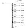
검출 배선(180)은 제 1 전원 전압(ELVDD)이 인가되는 제 1 전원 전압 공급 배선(135)과 표시 패널(130) 내에서 연결될 수 있다. 예를 들어, 제 1 전원 전압(ELVDD)은 표시 패널(130)에 공급되는 고전원 전압일 수 있다. 전압 공급부(150)에서 생성된 제 1 전원 전압(ELVDD)은 제 1 전원 전압 공급 배선(135)을 통해 표시 패널(130)의 각 화소들에 공급될 수 있다. 이 때, 전압 공급부(150)와 표시 패널(130)을 연결하는 배선 및 제 1 전원 전압 공급 배선(135)의 내부 저항에 의해 제 1 전원 전압(ELVDD)이 강하될 수 있다. 검출 배선(180)은 제 1 전원 전압(ELVDD)이 공급되는 전압 공급부(150)에서 일정 거리 이격된 위치(P)에서 제1 전원 전압 공급 배선(135)과 연결될 수 있다. 따라서, 검출부(120)는 검출 배선(180)을 통해 제 1 전원 전압 공급 배선(135)에서 전압 강하가 발생된 후의 제 1 전원 전압(ELVDD)을 측정할 수 있다. 저해상도 모델의 표시 패널(130)의 경우, 검출 배선(180)은 표시 패널(130)의 표시 영역(DA)을 가로질러 직선으로 형성될 수 있다. 고해상도 모델의 표시 패널(130)의 경우, 표시 패널(130)의 표시 영역(DA)에는 다수의 배선들과 화소들이 배치되므로, 검출 배선(180)은 표시 패널(130)의 비표시 영역(NA)을 둘러서 형성될 수 있다.The
검출부(120)는 검출 배선(180)을 통해 표시 패널(130) 내의 제 1 전원 전압(ELVDD)을 측정하고, 제 1 전원 전압(ELVDD)과 기 설정된 제 1 기준 전압을 비교하여 표시 패널(130)의 로드량에 상응하는 제 1 전압(V1)으로 출력할 수 있다. 검출 배선(180)은 전원 공급부에서 일정 거리 이격된 위치(P)에서 제 1 전원 전압 공급 배선(135)과 연결되므로, 검출부(120)는 검출 배선(180)을 통해 제 1 전원 전압 공급 배선(135)에서 전압 강하가 발생된 후의 제 1 전원 전압(ELVDD)을 측정할 수 있다. 검출부(120)는 제 1 전원 전압(ELVDD)과 기 설정된 제 1 기준 전압을 비교하여 표시 패널(130)의 로드량에 상응하는 제 1 전압으로 출력할 수 있다. 제 1 기준 전압은, 표시 패널(130)에서 백색 영상이 표시될 때, 검출 배선(180)을 통해서 측정되는 제 1 전원 전압(ELVDD)일 수 있다. 백색 영상은 발광 면적이 100%이므로, 표시 패널(130)에서 백색 영상이 표시될 때 제 1 전원 전압(ELVDD)의 전압 강하량이 최대일 수 있다. 검출부(120)는 제 1 전원 전압(ELVDD)과 제 1 기준 전압의 차를 제 1 전압(V1)으로 출력하는 비교기를 포함할 수 있다.The
로드 조절부(140)는 검출된 로드량 및 로딩 이펙트 설정에 따라 로드 조절량을 결정하고, 결정된 로드 조절량에 상응하는 제 2 전압(V2)을 출력할 수 있다. 로딩 이펙트 설정에 따라 로드 조절량의 크기 및 극성이 결정될 수 있다. 로딩 이펙트 설정은 표시 패널(130)을 포함하는 표시 장치의 사용 환경을 고려하여 세트 업체에서 설정할 수 있다. 또한, 로딩 이펙트 설정은 사용자의 선택에 의해 설정될 수 있다. 예를 들어, 표시 패널(130)을 포함하는 표시 장치를 야외에서 사용하는 경우, 로드 조절량이 양의 값을 갖도록 로딩 이펙트 설정이 결정될 수 있다. 이와는 반대로, 표시 패널(130)을 포함하는 표시 장치를 실내에서 사용하는 경우, 로드 조절량이 음의 값을 갖도록 로딩 이펙트 설정이 결정될 수 있다. 로드 조절부(140)는 로드량 및 로딩 이펙트 설정에 따라 로드 조절량의 크기를 결정하는 제 1 디코더 및 로딩 이펙트 설정에 따라 로드 조절량의 극성을 결정하는 제 2 디코더를 포함할 수 있다. 제 1 디코더는 제 1 전압(V1)이 일정 비율로 분압된 분압 전압들을 생성하고, 로딩 이펙트 설정에 따라 분압 전압들 중 하나를 선택하여 제 3 전압으로 출력할 수 있다. 제 2 디코더는 제3 전압의 극성을 반전시키는 인버터 및 제 3 전압의 극성을 유지시키는 버퍼를 포함할 수 있다. 제 1 디코더는 로딩 이펙트 설정에 따라 제 2 디코더의 인버터 또는 버퍼와 선택적으로 연결될 수 있다. 로드 조절부(140)는 제 1 디코더 및 제 2 디코더에서 크기 및 극성이 결정된 로드 조절량에 상응하는 제 2 전압(V2)을 출력할 수 있다.The
감마 기준 전압 생성부(160)는 결정된 로드 조절량에 따라 감마 기준 전압(Vreg)을 조절할 수 있다. 감마 기준 전압(Vreg)은 감마 전압 생성부로 공급될 수 있고, 감마 전압 생성부는 감마 기준 전압(Vreg)에 기초하여 복수의 감마 전압들을 생성할 수 있다. 감마 기준 전압 생성부(160)는 로드 조절량에 따라 감마 기준 전압(Vreg)을 증가시키거나 감소시킬 수 있다. 감마 기준 전압 생성부(160)는 기 설정된 제 2 기준 전압에 로드 조절량에 상응하는 제 2 전압(V2)을 더하는 연산 증폭기를 포함할 수 있다. 이 때, 제 2 기준 전압은 기 설정된 감마 커브를 갖는 감마 전압들을 생성하기 위해 설정된 전압일 수 있다. 제 2 전압(V2)이 양의 값을 갖는 경우, 감마 기준 전압 생성부(160)는 제 2 기준 전압보다 큰 감마 기준 전압(Vreg)을 생성할 수 있다. 이 경우, 감마 전압 생성부에서 생성되는 감마 전압들의 전압 레벨들이 증가하여 표시 패널(130)을 포함하는 표시 장치의 야외 시인성이 향상될 수 있다. 제 2 전압(V2)이 음의 값을 갖는 경우, 감마 기준 전압 생성부(160)는 제 2 기준 전압보다 작은 감마 기준 전압(Vreg)을 생성할 수 있다. 이 경우, 표시 패널(130)의 로딩 이펙트에 의해 증가하였던 감마 전압들의 전압 레벨들이 감소하여 표시 패널(130)을 포함하는 표시 장치의 색 정확도가 향상될 수 있다.The gamma
상술한 바와 같이, 본 발명의 실시예들에 따른 로딩 이펙트 제어 장치(100)는 검출 배선(180)을 통해서 표시 패널(130) 내의 제 1 전원 전압(ELVDD)을 측정하고, 제 1 전원 전압(ELVDD)과 제 1 기준 전압을 비교하여 표시 패널(130)의 로드량을 산출하며, 로드량 및 로딩 이펙트 설정에 따라 로드 조절량을 결정하여 감마 기준 전압(Vreg)을 생성함으로써, 표시 패널(130)의 색 정확도 또는 시인성을 향상시킬 수 있다.As described above, the loading
도 3은 도 1의 로딩 이펙트 제어 장치에 포함되는 검출부를 나타내는 회로도이다.3 is a circuit diagram showing a detection unit included in the loading effect control device of FIG.
도 3을 참조하면, 검출부(200)는 비교기(250) 및 제 1 저항(R1), 제 2 저항(R2), 제 3 저항(R3) 및 제 4 저항(R4)을 포함할 수 있다. 검출부(200)는 검출 배선을 통해 측정되는 제 1 전원 전압(ELVDD)을 측정하고, 제 1 전원 전압(ELVDD)과 기 설정된 제 1 기준 전압(Vref1)을 비교하여 표시 패널의 로드량에 상응하는 제 1 전압(V1)으로 출력할 수 있다. 비교기(250)는 제 1 입력 단자, 제 2 입력 단자 및 출력 단자를 포함할 수 있다. 제 1 저항(R1)은 검출 배선과 비교기(250)의 제 1 입력 단자 사이에 연결되고, 제 2 저항(R2)은 비교기(250)의 제 1 입력 단자와 출력 단자 사이에 연결될 수 있다. 제 3 저항(R3)은 제 1 기준 전압원과 비교기(250)의 제 2 입력 단자 사이에 연결되고, 제 4 저항(R4)은 비교기(250)의 제 2 입력 단자와 접지 사이에 연결될 수 있다. 비교기(250)는 검출 배선을 통해 제 1 입력 단자로 공급되는 제 1 전원 전압(ELVDD)과 제 1 기준 전압원에서 제 2 입력 단자로 공급되는 제 1 기준 전압(Vref1)의 차를 제 1 전압(V1)으로 출력할 수 있다. 제 1 전압(V1)은 로드 조절부로 공급될 수 있다.3, the
도 4는 도 1의 로딩 이펙트 제어 장치에 포함되는 로드 조절부를 나타내는 도면이고, 도 5는 도 4의 로드 조절부에 포함되는 제 1 디코더를 나타내는 회로도이며, 도 6a 및 도 6b는 도 4의 로드 조절부에 포함되는 제 2 디코더를 나타내는 회로도들이다.4 is a circuit diagram showing a first decoder included in the load control unit of FIG. 4, and FIGS. 6A and 6B are diagrams showing a load control unit included in the loading effect control apparatus of FIG. And a second decoder included in the adjustment section.
도 4를 참조하면, 로드 조절부(300)는 제 1 디코더(320) 및 제 2 디코더(340)를 포함할 수 있다. 제 1 디코더(320)는 로드량 및 로딩 이펙트 설정에 따라 로드 조절량의 크기를 결정할 수 있다. 도 5를 참조하면, 제 1 디코더(320)는 제 1 전압(V1)이 일정 비율로 분압된 분압 전압들을 생성하고, 로딩 이펙트 설정에 따라 상기 분압 전압들 중 하나를 선택하여 제 3 전압(V3)으로 출력할 수 있다. 구체적으로, 제 1 디코더(320)는 제 1 내지 제 10 저항(R1, ... , R10)을 포함하고, 제 1 전압(V1)에 기초하여 복수의 분압 전압들(SV1, ..., SV10)을 생성할 수 있다. 로딩 이펙트 설정에 따라 복수의 분압 전압들(SV1, ..., SV10) 중 하나가 제 3 전압(V3)으로 선택되어 제 2 디코더(340)에 공급될 수 있다. 일 실시예에서, 제 1 디코더(320)는 멀티플렉서(multiplexer)를 구비할 수 있다. 멀티플렉서는 로딩 이펙트 설정에 기초하여 복수의 분압 전압들(SV1, ..., SV10) 중 하나를 제 3 전압(V3)으로 선택하여 제 2 디코더(340)로 출력할 수 있다. 다른 실시예에서, 제 1 디코더(320)는 복수의 분압 전압들(SV1, ..., SV10) 각각의 출력단에 제 2 디코더와 연결 여부를 결정하는 스위치를 구비할 수 있다. 상기 스위치를 제어할 수 있는 스위치 제어부는 로딩 이펙트 설정에 기초하여 상기 스위치 중 하나를 제 2 디코더와 연결할 수 있다.Referring to FIG. 4, the
제 2 디코더(340)는 로딩 이펙트 설정에 따라 로드 조절량의 극성을 결정할 수 있다. 도 6a 및 도 6b를 참조하면, 제 2 디코더(340)는 인버터(342) 및 버퍼(344)를 포함할 수 있다. 제 1 디코더(320)에서 출력되는 제 3 전압(V3)은 로딩 이펙트 설정에 기초하여 인버터(342) 또는 버퍼(344)와 선택적으로 연결될 수 있다. 인버터(342)는 제 3 전압(V3)의 극성을 반전시킬 수 있다. 인버터(342)는 양의 값을 갖는 제 3 전압(V3)의 극성을 반전시켜 음의 값을 갖는 제 2 전압(V2)으로 출력하거나, 음의 값을 갖는 제 3 전압(V3)의 극성을 반전시켜 양의 값을 갖는 제 2 전압(V2)으로 출력할 수 있다. 버퍼(344)는 제 3 전압(V3)의 극성을 유지시킬 수 있다. 즉, 버퍼(344)는 제 3 전압(V3)을 그대로 제 2 전압(V2)으로 출력할 수 있다.The
로드 조절부(300)는 제 1 디코더(320) 및 제 2 디코더(340)에서 크기 및 극성이 결정된 로드 조절량에 상응하는 제 2 전압(V2)을 출력할 수 있다. 제 2 전압(V2)은 감마 기준 전압 생성부로 공급될 수 있다.The
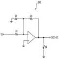
도 7은 도 1의 로딩 이펙트 제어 장치에 포함되는 감마 기준 전압 생성부를 나타내는 회로도이다.7 is a circuit diagram showing a gamma reference voltage generator included in the loading effect controller of FIG.
도 7을 참조하면, 감마 기준 전압 생성부(400)은 연산 증폭기(450), 제 1 저항(R1), 제 2 저항(R2), 제 3 저항(R3), 제 4 저항(R4) 및 제 5 저항(R5)을 포함할 수 있다. 감마 기준 전압 생성부(400)는 로드 조절부에서 공급되는 제 2 전압(V2)에 따라 감마 기준 전압(Vreg)을 조절할 수 있다. 연산 증폭기(450)는 제 1 입력 단자, 제 2 입력 단자 및 출력 단자를 포함할 수 있다. 제 1 저항(R1)은 로드 조절부와 제 1 입력 단자 사이에 연결되고, 제 2 저항(R2)은 제 1 입력 단자와 출력 단자 사이에 연결될 수 있다. 제 3 저항(R3)은 제 2 기준 전압원과 제 2 입력 단자 사이에 연결되고, 제 4 저항(R4)은 제 2 입력 단자와 접지 사이에 연결될 수 있으며, 제 5 저항(R5)은 출력 단자와 접지 사이에 연결될 수 있다. 로드 조절부에서 공급되는 제 2 전압(V2)은 음의 값 또는 양의 값을 가질 수 있다. 연산 증폭기(450)는 기 설정된 제 2 기준 전압(Vref2)에 제 2 전압(V2)을 더하여 감마 기준 전압(Vreg)을 조절할 수 있다. 이 때, 제 2 기준 전압(Vref2)은 기 설정된 감마 커브를 갖는 감마 전압들을 생성하기 위해 설정된 전압일 수 있다. 제 2 전압(V2)이 양의 값을 갖는 경우, 감마 기준 전압 생성부(400)는 제 2 기준 전압(Vref2)보다 큰 감마 기준 전압(Vreg)을 생성할 수 있다. 이 경우, 감마 전압 생성부에서 생성되는 감마 전압들의 전압 레벨들이 증가하여 표시 패널을 포함하는 표시 장치의 야외 시인성이 향상될 수 있다. 제 2 전압(V2)이 음의 값을 갖는 경우, 감마 기준 전압 생성부(400)는 제 2 기준 전압(Vref2)보다 작은 감마 기준 전압(Vreg)을 생성할 수 있다. 이 경우, 표시 패널(130)의 로딩 이펙트에 의해 증가하였던 감마 전압들의 전압 레벨들이 감소하여 표시 패널을 포함하는 표시 장치의 색 정확도가 향상될 수 있다.Referring to FIG. 7, the gamma
도 8은 본 발명의 실시예들에 따른 유기 발광 표시 장치를 나타내는 블록도이다.8 is a block diagram illustrating an organic light emitting display according to embodiments of the present invention.
도 8을 참조하면, 유기 발광 표시 장치(500)는 표시 패널(510), 전원 공급부(520), 로딩 이펙트 제어부(530), 데이터 구동부(540), 스캔 구동부(550) 및 타이밍 제어부(560)를 포함할 수 있다. 이 때, 로딩 이펙트 제어부(530)는 도 1의 로딩 이펙트 제어 장치(100)에 상응할 수 있다.8, the
표시 패널(510)은 복수의 화소들(미도시)을 포함할 수 있다. 일 실시예에서, 화소들 각각은 화소 회로, 구동 트랜지스터 및 유기 발광 다이오드를 포함할 수 있다. 이 경우, 화소 회로가 스캔 라인(SLn)으로부터 공급되는 스캔 신호에 응답하여 데이터 라인(DLm)으로부터 공급되는 데이터 신호를 구동 트랜지스터에 전달하면, 구동 트랜지스터는 데이터 신호에 기초하여 유기 발광 다이오드를 흐르는 구동 전류를 조절할 수 있고, 유기 발광 다이오드는 상기 구동 전류에 기초하여 발광할 수 있다. 표시 패널(510) 내에는 검출 배선이 형성될 수 있다. 검출 배선은 제 1 전원 전압(ELVDD)이 인가되는 제 1 전원 전압 공급 배선과 표시 패널(510) 내에서 연결될 수 있다. 예를 들어, 제 1 전원 전압(ELVDD)은 표시 패널(510)에 공급되는 고전원 전압일 수 있다. 전압 공급부(520)에서 생성된 제 1 전원 전압(ELVDD)은 제 1 전원 전압 공급 배선을 통해 표시 패널(510)의 각 화소들에 공급될 수 있다. 검출 배선은 제 1 전원 전압(ELVDD)이 공급되는 전압 공급부(520)에서 일정 거리 이격된 위치에서 제1 전원 전압 공급 배선과 연결될 수 있다. 따라서, 로딩 이펙트 제어부(530)는 검출 배선을 통해 제 1 전원 전압 공급 배선에서 전압 강하가 발생된 후의 제 1 전원 전압(ELVDD)을 측정할 수 있다.The
전원 공급부(520)는 표시 패널의 복수의 화소들을 구동시키기 위한 제 1 전원 전압(ELVDD) 및 제 2 전원 전압(ELVSS)을 공급할 수 있다.The
로딩 이펙트 제어부(530)는 표시 패널(510)에서 검출되는 제 1 전원 전압(ELVDD)과 기 설정된 제 1 기준 전압의 차에 기초하여 표시 패널(510)의 로드량을 산출하고, 검출된 로드량 및 로딩 이펙트 설정에 따라 로드 조절량을 결정하며, 결정된 로드 조절량에 따라 감마 기준 전압을 조절할 수 있다. 구체적으로, 로딩 이펙트 제어부(530)는 검출부, 로드 조절부, 감마 기준 전압 생성부 및 검출 배선을 포함할 수 있다. 검출 배선은 제 1 전원 전압(ELVDD)이 인가되는 제 1 전원 전압 공급 배선과 표시 패널(510) 내에서 연결될 수 있다. 검출부는 검출 배선을 통해 표시 패널(510) 내의 제 1 전원 전압(ELVDD)을 측정하고, 제 1 전원 전압(ELVDD)과 기 설정된 제 1 기준 전압을 비교하여 표시 패널(510)의 로드량에 상응하는 제 1 전압으로 출력할 수 있다. 검출 배선은 전원 공급부(520)에서 일정 거리 이격된 위치에서 제 1 전원 전압 공급 배선과 연결되므로, 검출부는 검출 배선을 통해 제 1 전원 전압 공급 배선에서 전압 강하가 발생된 후의 제 1 전원 전압(ELVDD)을 측정할 수 있다. 검출부는 제1 전원 전압(ELVDD)과 기 설정된 제 1 기준 전압을 비교하여 표시 패널(510)의 로드량에 상응하는 제 1 전압으로 출력할 수 있다. 제 1 기준 전압은, 표시 패널(510)에서 백색 영상이 표시될 때, 검출 배선을 통해서 측정되는 제 1 전원 전압(ELVDD)일 수 있다. 검출부는 제 1 전원 전압(ELVDD)과 제 1 기준 전압의 차를 제 1 전압으로 출력하는 비교기를 포함할 수 있다. 로드 조절부는 검출된 로드량 및 로딩 이펙트 설정에 따라 로드 조절량을 결정하고, 결정된 로드 조절량에 상응하는 제 2 전압을 출력할 수 있다. 로드 조절부는 로딩 이펙트 설정에 따라 로드 조절량의 크기를 결정하는 제 1 디코더 및 로딩 이펙트 설정에 따라 로드 조절량의 극성을 결정하는 제 2 디코더를 포함할 수 있다. 제 1 디코더는 제 1 전압이 일정 비율로 분압된 분압 전압들을 생성하고, 로딩 이펙트 설정에 따라 분압 전압들 중 하나를 선택하여 제 3 전압으로 출력할 수 있다. 제 2 디코더는 제 3 전압의 극성을 반전시키는 인버터 및 제 3 전압의 극성을 유지시키는 버퍼를 포함할 수 있다. 제 1 디코더는 로딩 이펙트 설정에 따라 제 2 디코더의 인버터 또는 버퍼와 선택적으로 연결될 수 있다. 로드 조절부는 제 1 디코더 및 제 2 디코더에서 크기 및 극성이 결정된 로드 조절량에 상응하는 제 2 전압을 출력할 수 있다. 감마 기준 전압 생성부는 결정된 로드 조절량에 따라 감마 기준 전압(Vreg)을 조절할 수 있다. 감마 기준 전압(Vreg)은 타이밍 제어부(560)의 내부에 배치되는 감마 전압 생성부로 공급될 수 있고, 감마 전압 생성부는 감마 기준 전압(Vreg)에 기초하여 복수의 감마 전압들을 생성할 수 있다. 감마 기준 전압 생성부는 기 설정된 제 2 기준 전압에 로드 조절량에 상응하는 제 2 전압을 더하는 연산 증폭기를 포함할 수 있다. 이 때, 제 2 기준 전압은 기 설정된 감마 커브를 갖는 감마 전압들을 생성하기 위해 설정된 전압일 수 있다. 제 2 전압이 양의 값을 갖는 경우, 감마 기준 전압 생성부는 제 2 기준 전압보다 큰 감마 기준 전압(Vreg)을 생성할 수 있다. 이 경우, 감마 전압 생성부에서 생성되는 감마 전압들의 전압 레벨들이 증가하여 표시 패널(510)을 포함하는 표시 장치의 야외 시인성이 향상될 수 있다. 제 2 전압이 음의 값을 갖는 경우, 감마 기준 전압 생성부는 제 2 기준 전압보다 작은 감마 기준 전압(Vreg)을 생성할 수 있다. 이 경우, 표시 패널(510)의 로딩 이펙트에 의해 증가하였던 감마 전압들의 전압 레벨들이 감소하여 표시 패널(510)을 포함하는 표시 장치의 색 정확도가 향상될 수 있다. 도 8에는 로딩 이펙트 제어부(530)와 타이밍 제어부(560)와 연결되는 것으로 도시하였으나, 로딩 이펙트 제어부(530)는 타이밍 제어부(560) 내에 구비될 수 있다.The
스캔 구동부(550)는 복수의 스캔 라인들(SLn)을 통해 상기 화소들에 스캔 신호를 공급할 수 있고, 데이터 구동부(540)는 상기 스캔 신호에 따라 복수의 데이터 라인들(DLm)을 통해 상기 화소들에 데이터 신호를 공급할 수 있다. 타이밍 제어부(560)는 데이터 구동부(540) 및 스캔 구동부(550)를 제어하는 제어 신호를 생성할 수 있다.The
상술한 바와 같이, 본 발명의 실시예들에 따른 유기 발광 표시 장치(500)는 로딩 이펙트 설정에 따라 감마 기준 전압을 조절하는 로딩 이펙트 제어부(530)를 포함할 수 있다. 로딩 이펙트 제어부(530)는 검출 배선을 통해 표시 패널(510)의 제 1 전원 전압(ELVDD)을 측정하고, 제 1 전원 전압(ELVDD)과 제 1 기준 전압을 비교하여 표시 패널(510)의 로드량을 산출하며, 로드량 및 로딩 이펙트 설정에 따라 로드 조절량을 결정하여 감마 기준 전압(Vreg)을 생성함으로써, 표시 패널(510)의 색 정확도 및 시인성을 향상시킬 수 있다.As described above, the
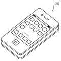
도 9는 도 8의 유기 발광 표시 장치를 포함하는 전자 기기를 나타내는 도면이고, 도 10은 도 9의 전자 기기가 스마트폰으로 구현되는 일 예를 나타내는 도면이다.FIG. 9 is a view showing an electronic device including the organic light emitting diode display of FIG. 8, and FIG. 10 is a diagram illustrating an example of the electronic device of FIG. 9 being implemented by a smart phone.
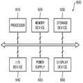
도 9 및 도 10을 참조하면, 전자 기기(600)는 프로세서(610), 메모리 장치(620), 저장 장치(630), 입출력 장치(640), 파워 서플라이(650) 및 표시 장치(660)를 포함할 수 있다. 이 때, 표시 장치(660)는 도 9의 유기 발광 표시 장치(500)에 상응할 수 있다. 나아가 전자 기기(600)는 비디오 카드, 사운드 카드, 메모리 카드, USB 장치 등과 통신하건, 다른 시스템들과 통신할 수 있는 여러 포트(port)들을 더 포함할 수 있다. 한편, 도 10에 도시된 바와 같이, 전자 기기(600)는 스마트폰(700)으로 구현될 수 있으나, 전자 기기(600)가 그에 한정되는 것은 아니다.9 and 10, an
프로세서(610)는 특정 계산들 또는 태스크(task)들을 수행할 수 있다. 일 실시예에서 프로세서(610)는 마이크로프로세서(micro processor), 중앙 처리 장치(CPU) 등일 수 있다. 프로세서(610)는 어드레스 버스(address bus), 제어 버스(control bus) 및 데이터 버스(data bus) 등을 통하여 다른 구성 요소들에 연결될 수 있다. 또한, 프로세서(610)는 주변 구성요소 상호연결(Peripheral Component Interconnect; PCI) 버스와 같은 확장 버스에도 연결될 수 있다. 메모리 장치(620)는 전자 기기(600)의 동작에 필요한 데이터들을 저장할 수 있다. 예를 들어, 메모리 장치(620)는 EPROM(Erasable Programmable Read-Only Memory), EEPROM(Electrically Erasable Programmable Read-Only Memory), 플래시 메모리(Flash Memory), PRAM(Phase Change Random Access Memory), RRAM(Resistance Random Access Memory), NFGM(Nano Floating Gate Memory), PoRAM(Polymer Random Access Memory), MRAM(Magnetic Random Access Memory), FRAM(Ferroelectric Random Access Memory) 등과 같은 비휘발성 메모리 장치 및/또는 DRAM(Dynamic Random Access Memory), SRAM(Static Random Access Memory), 모바일 DRAM 등과 같은 휘발성 메모리 장치를 포함할 수 있다. 저장 장치(630)는 솔리드 스테이트 드라이브(Solid State Drive; SSD), 하드 디스크 드라이브(Hard Disk Drive; HDD), 씨디롬(CD-ROM) 등을 포함할 수 있다.The
입출력 장치(640)는 키보드, 키패드, 터치패드, 터치스크린, 마우스 등과 같은 입력 수단, 및 스피커, 프린터 등과 같은 출력 수단을 포함할 수 있다. 표시 장치(660)는 입출력 장치(640) 내에 구비될 수도 있다. 파워 서플라이(650)는 전자 기기(600)의 동작에 필요한 파워를 공급할 수 있다. 표시 장치(660)는 상기 버스들 또는 다른 통신 링크를 통해서 다른 구성 요소들에 연결될 수 있다. 상술한 바와 같이, 표시 장치(660)는 표시 패널, 전원 공급부, 로딩 이펙트 제어부, 데이터 구동부, 스캔 구동부 및 타이밍 제어부를 포함할 수 있다. 표시 패널 내에는 검출 배선이 형성될 수 있다. 검출 배선은 제 1 전원 전압이 인가되는 제 1 전원 전압 공급 배선과 표시 패널 내에서 연결될 수 있다. 전압 공급부에서 생성된 제 1 전원 전압은 제 1 전원 전압 공급 배선을 통해 표시 패널의 각 화소들에 공급될 수 있다. 검출 배선은 제 1 전원 전압이 공급되는 전압 공급부에서 일정 거리 이격된 위치에서 제1 전원 전압 공급 배선과 연결될 수 있다. 전원 공급부는 표시 패널의 복수의 화소들을 구동시키기 위한 제 1 전원 전압 및 제 2 전원 전압을 공급할 수 있다. 로딩 이펙트 제어부는 표시 패널에서 검출되는 제 1 전원 전압과 기 설정된 제 1 기준 전압의 차에 기초하여 표시 패널의 로드량을 산출하고, 검출된 로드량 및 로딩 이펙트 설정에 따라 로드 조절량을 결정하며, 결정된 로드 조절량에 따라 감마 기준 전압을 조절할 수 있다. 구체적으로, 로딩 이펙트 제어부는 검출부, 로드 조절부, 감마 기준 전압 생성부 및 검출 배선을 포함할 수 있다. 검출부는 검출 배선을 통해 표시 패널 내의 제 1 전원 전압을 측정할 수 있다. 검출 배선은 전원 공급부에서 일정 거리 이격된 위치에서 제 1 전원 전압 공급 배선과 연결되므로, 검출부는 검출 배선을 통해 제 1 전원 전압 공급 배선에서 전압 강하가 발생된 후의 제 1 전원 전압을 측정할 수 있다. 검출부는 제 1 전원 전압과 기 설정된 제 1 기준 전압을 비교하여 표시 패널의 로드량에 상응하는 제 1 전압으로 출력할 수 있다. 로드 조절부는 검출된 로드량 및 로딩 이펙트 설정에 따라 로드 조절량을 결정하고, 결정된 로드 조절량에 상응하는 제 2 전압을 출력할 수 있다 로드 조절부는 로드량 및 로딩 이펙트 설정에 따라 로드 조절량의 크기를 결정하는 제 1 디코더 및 로딩 이펙트 설정에 따라 로드 조절량의 극성을 결정하는 제 2 디코더를 포함할 수 있다. 감마 기준 전압 생성부는 결정된 로드 조절량에 따라 감마 기준 전압을 조절할 수 있다. 제 2 전압이 양의 값을 갖는 경우, 감마 기준 전압 생성부는 제 2 기준 전압보다 큰 감마 기준 전압을 생성할 수 있다. 이 경우, 감마 전압 생성부에서 생성되는 감마 전압들의 전압 레벨들이 증가하여 표시 패널을 포함하는 표시 장치의 야외 시인성이 향상될 수 있다. 제 2 전압이 음의 값을 갖는 경우, 감마 기준 전압 생성부는 제 2 기준 전압보다 작은 감마 기준 전압을 생성할 수 있다. 이 경우, 표시 패널의 로딩 이펙트에 의해 증가하였던 감마 전압들의 전압 레벨들이 감소하여 표시 패널을 포함하는 표시 장치의 색 정확도가 향상될 수 있다. 스캔 구동부는 복수의 스캔 라인들을 통해 상기 화소들에 스캔 신호를 공급할 수 있고, 데이터 구동부는 상기 스캔 신호에 따라 복수의 데이터 라인들을 통해 상기 화소들에 데이터 신호를 공급할 수 있다. 타이밍 제어부는 데이터 구동부 및 스캔 구동부를 제어하는 제어 신호를 생성할 수 있다.The input /
이와 같이, 도 9의 전자 기기(600)는 로딩 이펙트 설정에 따라 감마 기준 전압을 조절하는 표시 장치(660)를 포함할 수 있다. 표시 장치(660)는 검출 배선을 통해 표시 패널의 제 1 전원 전압을 측정하고 제 1 전원 전압과 제 1 기준 전압을 비교하여 표시 패널의 로드량을 산출하며, 로드량 및 로딩 이펙트 설정에 따라 로드 조절량을 결정하여 감마 기준 전압을 생성함으로써, 표시 패널의 색 정확도 및 시인성을 향상시킬 수 있다.As such, the
본 발명은 표시 장치를 구비한 모든 전자 기기에 적용될 수 있다. 예를 들어, 본 발명은 텔레비전, 컴퓨터 모니터, 노트북, 디지털 카메라, 휴대폰, 스마트폰, 스마트패드, 타블렛 PC, 피디에이(PDA), 피엠피(PMP), MP3 플레이어, 네비게이션, 비디오폰 등에 적용될 수 있다.The present invention can be applied to all electronic apparatuses having a display device. For example, the present invention can be applied to a television, a computer monitor, a notebook, a digital camera, a mobile phone, a smart phone, a smart pad, a tablet PC, a PDA, a PMP, an MP3 player,
이상에서는 본 발명의 예시적인 실시예들을 참조하여 설명하였지만, 해당 기술 분야에서 통상의 지식을 가진 자라면 하기의 특허 청구의 범위에 기재된 본 발명의 사상 및 영역으로부터 벗어나지 않는 범위 내에서 본 발명을 다양하게 수정 및 변경시킬 수 있음을 이해할 수 있을 것이다.While the present invention has been particularly shown and described with reference to exemplary embodiments thereof, it will be understood by those of ordinary skill in the art that various changes in form and details may be made therein without departing from the spirit and scope of the invention as defined by the appended claims. It will be understood that the invention may be modified and varied without departing from the scope of the invention.
100: 로딩 이펙트 제어 장치120, 200: 검출부
140, 300: 로드 조절부
160, 400: 감마 기준 전압 생성부
180: 검출 배선500: 유기 발광 표시 장치
600: 전자기기700: 스마트폰100: Loading
140, and 300:
160, 400: gamma reference voltage generator
180: detection wiring 500: organic light emitting display
600: electronic device 700: smart phone
Claims (20)
Translated fromKorean상기 검출 배선을 통해 상기 표시 패널 내에서의 상기 제 1 전원 전압을 측정하고, 상기 제 1 전원 전압과 기 설정된 제 1 기준 전압을 비교하여 상기 표시 패널의 로드량에 상응하는 제 1 전압으로 출력하는 검출부;
상기 검출된 로드량 및 로딩 이펙트 설정에 따라 로드 조절량을 결정하고, 상기 결정된 로드 조절량에 상응하는 제 2 전압을 출력하는 로드 조절부; 및
상기 결정된 로드 조절량에 따라 감마 기준 전압을 조절하는 감마 기준 전압 생성부를 포함하는 로딩 이펙트 제어 장치.A detection wiring connected in the display panel to the first power supply voltage supply wiring to which the first power supply voltage is applied;
The first power supply voltage in the display panel is measured through the detection wiring and the first power supply voltage is compared with a predetermined first reference voltage to output a first voltage corresponding to a load amount of the display panel A detection unit;
A load adjusting unit for determining a load adjustment amount according to the detected load amount and the loading effect setting, and outputting a second voltage corresponding to the determined load adjustment amount; And
And a gamma reference voltage generator for adjusting the gamma reference voltage according to the determined load adjustment amount.
상기 로드량 및 상기 로딩 이펙트 설정에 따라 상기 로드 조절량의 크기를 결정하는 제 1 디코더; 및
상기 로딩 이펙트 설정에 따라 상기 로드 조절량의 극성을 결정하는 제 2 디코더를 포함하는 것을 특징으로 하는 로딩 이펙트 제어 장치.2. The apparatus of claim 1, wherein the rod adjuster
A first decoder for determining a magnitude of the load adjustment amount according to the load amount and the loading effect setting; And
And a second decoder for determining the polarity of the load adjustment amount according to the loading effect setting.
상기 제 3 전압의 극성을 반전시키는 인버터; 및
상기 제 3 전압의 극성을 유지시키는 버퍼를 포함하는 것을 특징으로 하는 로딩 이펙트 제어 장치.7. The apparatus of claim 6, wherein the second decoder
An inverter for inverting a polarity of the third voltage; And
And a buffer for maintaining the polarity of the third voltage.
상기 표시 패널에 제 1 전원 전압 및 제 2 전원 전압을 공급하는 전원 공급부;
상기 표시 패널에서 검출되는 상기 제 1 전원 전압과 기 설정된 제 1 기준 전압의 차를 상기 표시 패널의 로드량으로 산출하고, 상기 산출된 로드량 및 로딩 이펙트 설정에 따라 로드 조절량을 결정하며, 상기 결정된 로드 조절량에 따라 감마 기준 전압을 조절하는 로딩 이펙트 제어부;
상기 표시 패널에 데이터 신호를 공급하는 데이터 구동부;
상기 표시 패널에 스캔 신호를 공급하는 스캔 구동부; 및
상기 데이터 구동부 및 상기 스캔 구동부를 제어하는 제어 신호를 생성하는 타이밍 제어부를 포함하는 유기 발광 표시 장치.A display panel including a plurality of pixels;
A power supply unit for supplying a first power supply voltage and a second power supply voltage to the display panel;
Wherein the control unit calculates a difference between the first power supply voltage detected by the display panel and a predetermined first reference voltage as a load amount of the display panel and determines a load adjustment amount according to the calculated load amount and the loading effect setting, A loading effect controller for adjusting a gamma reference voltage according to a load adjustment amount;
A data driver for supplying a data signal to the display panel;
A scan driver for supplying a scan signal to the display panel; And
And a timing controller for generating a control signal for controlling the data driver and the scan driver.
상기 제 1 전원 전압이 인가되는 제 1 전원 전압 공급 배선과 상기 표시 패널 내에서 연결되는 검출 배선;
상기 검출 배선을 통해 상기 표시 패널 내에서의 상기 제 1 전원 전압을 측정하고, 상기 제 1 전원 전압과 기 설정된 제 1 기준 전압을 비교하여 상기 표시 패널의 로드량에 상응하는 제 1 전압으로 출력하는 검출부;
상기 검출된 로드량 및 로딩 이펙트 설정에 따라 로드 조절량을 결정하고, 상기 결정된 로드 조절량에 상응하는 제 2 전압을 출력하는 로드 조절부; 및
상기 결정된 로드 조절량에 따라 감마 기준 전압을 조절하는 감마 기준 전압 생성부를 포함하는 것을 특징으로 하는 유기 발광 표시 장치.11. The apparatus according to claim 10, wherein the loading effect controller
A detection wiring connected in the display panel to a first power supply voltage supply line to which the first power supply voltage is applied;
The first power supply voltage in the display panel is measured through the detection wiring and the first power supply voltage is compared with a predetermined first reference voltage to output a first voltage corresponding to a load amount of the display panel A detection unit;
A load adjusting unit for determining a load adjustment amount according to the detected load amount and the loading effect setting, and outputting a second voltage corresponding to the determined load adjustment amount; And
And a gamma reference voltage generator for adjusting the gamma reference voltage according to the determined load adjustment amount.
상기 로드량 및 상기 로딩 이펙트 설정에 따라 상기 로드 조절량의 크기를 결정하는 제 1 디코더; 및
상기 로딩 이펙트 설정에 따라 상기 로드 조절량의 극성을 결정하는 제 2 디코더를 포함하는 것을 특징으로 하는 유기 발광 표시 장치.12. The apparatus of claim 11, wherein the rod adjuster
A first decoder for determining a magnitude of the load adjustment amount according to the load amount and the loading effect setting; And
And a second decoder for determining the polarity of the load adjustment amount according to the loading effect setting.
상기 제 3 전압의 극성을 반전시키는 인버터; 및
상기 제 3 전압의 극성을 유지시키는 버퍼를 포함하는 것을 특징으로 하는 유기 발광 표시 장치.17. The apparatus of claim 16, wherein the second decoder
An inverter for inverting a polarity of the third voltage; And
And a buffer for maintaining the polarity of the third voltage.
Priority Applications (2)
| Application Number | Priority Date | Filing Date | Title |
|---|---|---|---|
| KR1020140149338AKR102229371B1 (en) | 2014-10-30 | 2014-10-30 | Loading effect control unit and organic light emitting display device having the same |
| US14/925,154US9922586B2 (en) | 2014-10-30 | 2015-10-28 | Loading effect control device and organic light emitting display device having the same |
Applications Claiming Priority (1)
| Application Number | Priority Date | Filing Date | Title |
|---|---|---|---|
| KR1020140149338AKR102229371B1 (en) | 2014-10-30 | 2014-10-30 | Loading effect control unit and organic light emitting display device having the same |
Publications (2)
| Publication Number | Publication Date |
|---|---|
| KR20160053051Atrue KR20160053051A (en) | 2016-05-13 |
| KR102229371B1 KR102229371B1 (en) | 2021-03-19 |
Family
ID=55853310
Family Applications (1)
| Application Number | Title | Priority Date | Filing Date |
|---|---|---|---|
| KR1020140149338AActiveKR102229371B1 (en) | 2014-10-30 | 2014-10-30 | Loading effect control unit and organic light emitting display device having the same |
Country Status (2)
| Country | Link |
|---|---|
| US (1) | US9922586B2 (en) |
| KR (1) | KR102229371B1 (en) |
Cited By (4)
| Publication number | Priority date | Publication date | Assignee | Title |
|---|---|---|---|---|
| US11004395B2 (en) | 2018-04-23 | 2021-05-11 | Samsung Display Co., Ltd. | Display device |
| US11257462B2 (en) | 2019-10-28 | 2022-02-22 | Samsung Display Co., Ltd. | Display device, a method of generating compensation data for a display device, and a method of operating a display device |
| US11282900B2 (en) | 2018-11-30 | 2022-03-22 | Samsung Display Co., Ltd. | Display device with dummy pixels in a non-display area |
| US11961443B2 (en) | 2021-12-24 | 2024-04-16 | Lx Semicon Co., Ltd. | Display driving apparatus |
Families Citing this family (8)
| Publication number | Priority date | Publication date | Assignee | Title |
|---|---|---|---|---|
| KR102234713B1 (en)* | 2014-10-22 | 2021-03-31 | 엘지디스플레이 주식회사 | Generating circuit of gamma voltage and liquid crystal display device including the same |
| CN105469768A (en)* | 2016-01-15 | 2016-04-06 | 京东方科技集团股份有限公司 | Display module controller, control method display device |
| US20190019457A1 (en)* | 2017-07-11 | 2019-01-17 | Shenzhen China Star Optoelectronics Semiconductor Display Technology Co., Ltd. | Display device and method of driving the same |
| CN108053786B (en)* | 2018-02-07 | 2021-05-18 | 京东方科技集团股份有限公司 | Data drive module and failure detection method thereof, and display device |
| CN109192127B (en) | 2018-10-29 | 2022-06-24 | 合肥鑫晟光电科技有限公司 | Timing controller and driving method thereof, and display device |
| CN109509449B (en)* | 2018-12-19 | 2021-07-06 | 惠科股份有限公司 | Current regulating circuit, driving circuit and display device |
| CN111179804B (en)* | 2020-01-13 | 2023-04-18 | 合肥鑫晟光电科技有限公司 | Time schedule controller, display device and signal adjusting method |
| CN111540326A (en) | 2020-05-20 | 2020-08-14 | Tcl华星光电技术有限公司 | Display device driving and driving method thereof |
Citations (3)
| Publication number | Priority date | Publication date | Assignee | Title |
|---|---|---|---|---|
| KR20080095462A (en)* | 2007-04-24 | 2008-10-29 | 삼성에스디아이 주식회사 | Organic electroluminescent display and driving method thereof |
| KR20110090006A (en)* | 2010-02-02 | 2011-08-10 | 삼성모바일디스플레이주식회사 | Display device and driving method thereof |
| KR20120105064A (en)* | 2010-01-13 | 2012-09-25 | 파나소닉 주식회사 | Display apparatus and method for driving the same |
Family Cites Families (6)
| Publication number | Priority date | Publication date | Assignee | Title |
|---|---|---|---|---|
| KR100482343B1 (en) | 2002-10-07 | 2005-04-14 | 엘지.필립스 엘시디 주식회사 | Thin film transistor array substrate for protecting loading effect and manufacturing method thereof |
| KR20080045343A (en) | 2006-11-20 | 2008-05-23 | 삼성전자주식회사 | Display device |
| KR101479992B1 (en) | 2008-12-12 | 2015-01-08 | 삼성디스플레이 주식회사 | Method for compensating voltage drop and system therefor and display deivce including the same |
| KR20120100496A (en) | 2011-03-04 | 2012-09-12 | 삼성전자주식회사 | Voltage regulator and integrated circuit including the same |
| KR20120111675A (en)* | 2011-04-01 | 2012-10-10 | 삼성디스플레이 주식회사 | Organic light emitting display device, data driving apparatus for organic light emitting display device and driving method thereof |
| KR101914936B1 (en)* | 2011-12-29 | 2018-11-06 | 삼성디스플레이 주식회사 | Method and circuit for compensating gamma reference voltages |
- 2014
- 2014-10-30KRKR1020140149338Apatent/KR102229371B1/enactiveActive
- 2015
- 2015-10-28USUS14/925,154patent/US9922586B2/enactiveActive
Patent Citations (3)
| Publication number | Priority date | Publication date | Assignee | Title |
|---|---|---|---|---|
| KR20080095462A (en)* | 2007-04-24 | 2008-10-29 | 삼성에스디아이 주식회사 | Organic electroluminescent display and driving method thereof |
| KR20120105064A (en)* | 2010-01-13 | 2012-09-25 | 파나소닉 주식회사 | Display apparatus and method for driving the same |
| KR20110090006A (en)* | 2010-02-02 | 2011-08-10 | 삼성모바일디스플레이주식회사 | Display device and driving method thereof |
Cited By (6)
| Publication number | Priority date | Publication date | Assignee | Title |
|---|---|---|---|---|
| US11004395B2 (en) | 2018-04-23 | 2021-05-11 | Samsung Display Co., Ltd. | Display device |
| US11282900B2 (en) | 2018-11-30 | 2022-03-22 | Samsung Display Co., Ltd. | Display device with dummy pixels in a non-display area |
| US11832502B2 (en) | 2018-11-30 | 2023-11-28 | Samsung Display Co., Ltd. | Display device including dummy pixels in a non-display area |
| US12193312B2 (en) | 2018-11-30 | 2025-01-07 | Samsung Display Co., Ltd. | Display panel |
| US11257462B2 (en) | 2019-10-28 | 2022-02-22 | Samsung Display Co., Ltd. | Display device, a method of generating compensation data for a display device, and a method of operating a display device |
| US11961443B2 (en) | 2021-12-24 | 2024-04-16 | Lx Semicon Co., Ltd. | Display driving apparatus |
Also Published As
| Publication number | Publication date |
|---|---|
| KR102229371B1 (en) | 2021-03-19 |
| US20160125782A1 (en) | 2016-05-05 |
| US9922586B2 (en) | 2018-03-20 |
Similar Documents
| Publication | Publication Date | Title |
|---|---|---|
| KR102229371B1 (en) | Loading effect control unit and organic light emitting display device having the same | |
| CN107705751B (en) | Organic Light Emitting Display Device | |
| KR102401858B1 (en) | Display device supporting a low power mode and method of operating a display device | |
| CN105895021B (en) | Coupling compensator for display panel and display device including coupling compensator | |
| KR102533616B1 (en) | Rollable display device and electronic device including the same | |
| US9620054B2 (en) | Timing controller, organic light-emitting diode (OLED) display having the same and method for driving the OLED display | |
| KR102584643B1 (en) | Display device and electronic device having the same | |
| KR102469744B1 (en) | Display device and method for generating compensating data of the same | |
| KR102412677B1 (en) | Display device and electronic device having the same | |
| US10157567B2 (en) | Display apparatus and a method of operating the same | |
| KR102365205B1 (en) | Organic light emitting display device and method for setting gamma reference voltage thereof | |
| KR20160095231A (en) | Display device and electronic device having the same | |
| KR20160032294A (en) | Stretchable display device and method of compensating luminance of the same | |
| KR102349194B1 (en) | Power supply device and display device having the same | |
| KR102568160B1 (en) | Image processing device and display device having the same | |
| KR102464997B1 (en) | Display device and electronic device having the same | |
| CN111161672A (en) | Display device including folding area compensator | |
| KR20160007825A (en) | Degradation detecting method and degradation detecting device of display panel | |
| KR20170024646A (en) | Transparent display device and method of compensating an image for the same | |
| KR20160042284A (en) | Data voltage compensation circuit and display device including the same | |
| KR20160028621A (en) | Current sensing device of display panel and organic light emitting display device having the same | |
| KR102305356B1 (en) | Display device and electronic device having the same | |
| KR20170099429A (en) | Display device and electronic device having the same | |
| KR20200009168A (en) | Display device and driving method of the same | |
| KR20160022416A (en) | Display device and method of driving the same |
Legal Events
| Date | Code | Title | Description |
|---|---|---|---|
| PA0109 | Patent application | Patent event code:PA01091R01D Comment text:Patent Application Patent event date:20141030 | |
| PG1501 | Laying open of application | ||
| A201 | Request for examination | ||
| PA0201 | Request for examination | Patent event code:PA02012R01D Patent event date:20191007 Comment text:Request for Examination of Application Patent event code:PA02011R01I Patent event date:20141030 Comment text:Patent Application | |
| E902 | Notification of reason for refusal | ||
| PE0902 | Notice of grounds for rejection | Comment text:Notification of reason for refusal Patent event date:20200928 Patent event code:PE09021S01D | |
| E701 | Decision to grant or registration of patent right | ||
| PE0701 | Decision of registration | Patent event code:PE07011S01D Comment text:Decision to Grant Registration Patent event date:20201215 | |
| PR0701 | Registration of establishment | Comment text:Registration of Establishment Patent event date:20210312 Patent event code:PR07011E01D | |
| PR1002 | Payment of registration fee | Payment date:20210315 End annual number:3 Start annual number:1 | |
| PG1601 | Publication of registration |