KR20160048452A - Sound EQUIPMENT - Google Patents
Sound EQUIPMENTDownload PDFInfo
- Publication number
- KR20160048452A KR20160048452AKR1020140145092AKR20140145092AKR20160048452AKR 20160048452 AKR20160048452 AKR 20160048452AKR 1020140145092 AKR1020140145092 AKR 1020140145092AKR 20140145092 AKR20140145092 AKR 20140145092AKR 20160048452 AKR20160048452 AKR 20160048452A
- Authority
- KR
- South Korea
- Prior art keywords
- wheel
- housing
- button
- receiver
- acoustic
- Prior art date
- Legal status (The legal status is an assumption and is not a legal conclusion. Google has not performed a legal analysis and makes no representation as to the accuracy of the status listed.)
- Withdrawn
Links
- 238000000034methodMethods0.000claimsdescription10
- 239000000758substrateSubstances0.000claimsdescription6
- 238000004891communicationMethods0.000description13
- 239000000463materialSubstances0.000description4
- 230000005236sound signalEffects0.000description4
- 238000013461designMethods0.000description2
- 238000010586diagramMethods0.000description2
- 210000005069earsAnatomy0.000description2
- 230000014509gene expressionEffects0.000description2
- 238000004804windingMethods0.000description2
- 238000005452bendingMethods0.000description1
- 230000004397blinkingEffects0.000description1
- 230000008878couplingEffects0.000description1
- 238000010168coupling processMethods0.000description1
- 238000005859coupling reactionMethods0.000description1
- 238000011161developmentMethods0.000description1
- 230000000694effectsEffects0.000description1
- 238000005516engineering processMethods0.000description1
- 230000007246mechanismEffects0.000description1
- 238000012986modificationMethods0.000description1
- 230000004048modificationEffects0.000description1
- 230000008569processEffects0.000description1
- 230000009467reductionEffects0.000description1
Images


Classifications
- H—ELECTRICITY
- H02—GENERATION; CONVERSION OR DISTRIBUTION OF ELECTRIC POWER
- H02G—INSTALLATION OF ELECTRIC CABLES OR LINES, OR OF COMBINED OPTICAL AND ELECTRIC CABLES OR LINES
- H02G11/00—Arrangements of electric cables or lines between relatively-movable parts
- H02G11/02—Arrangements of electric cables or lines between relatively-movable parts using take-up reel or drum
- H—ELECTRICITY
- H04—ELECTRIC COMMUNICATION TECHNIQUE
- H04R—LOUDSPEAKERS, MICROPHONES, GRAMOPHONE PICK-UPS OR LIKE ACOUSTIC ELECTROMECHANICAL TRANSDUCERS; DEAF-AID SETS; PUBLIC ADDRESS SYSTEMS
- H04R1/00—Details of transducers, loudspeakers or microphones
- H04R1/10—Earpieces; Attachments therefor ; Earphones; Monophonic headphones
- H04R1/1033—Cables or cables storage, e.g. cable reels
- H—ELECTRICITY
- H04—ELECTRIC COMMUNICATION TECHNIQUE
- H04R—LOUDSPEAKERS, MICROPHONES, GRAMOPHONE PICK-UPS OR LIKE ACOUSTIC ELECTROMECHANICAL TRANSDUCERS; DEAF-AID SETS; PUBLIC ADDRESS SYSTEMS
- H04R1/00—Details of transducers, loudspeakers or microphones
- H04R1/10—Earpieces; Attachments therefor ; Earphones; Monophonic headphones
- H04R1/1041—Mechanical or electronic switches, or control elements
Landscapes
- Physics & Mathematics (AREA)
- Engineering & Computer Science (AREA)
- Acoustics & Sound (AREA)
- Signal Processing (AREA)
- Headphones And Earphones (AREA)
Abstract
Translated fromKoreanDescription
Translated fromKorean본 발명은 리시버를 하우징 내부로 인입출 가능한 음향기기에 관한 것이다.BACKGROUND OF THE INVENTION 1. Field of the Invention [0001] The present invention relates to an acoustic apparatus capable of pulling out a receiver into a housing.
음향기기는 단말기로부터 음향신호를 수신하고 마이크를 통해 수집한 음향정보를 단말기에 전송하는 음향장치를 의미한다. 종래에는 음향기기를 단말기의 이어잭에 단자를 꼽아 음향 신호를 받는 유선 방식을 이용하였으나, 이동성 및 사용의 편의성 측면에서 최근 무선통신방식의 음향기기의 수요가 증가하고 있다.A sound device refers to a sound device that receives a sound signal from a terminal and transmits the sound information collected through the microphone to the terminal. Conventionally, a wired system has been used in which a terminal is connected to a ear jack of a terminal to receive an acoustic signal. However, in recent years, demand for a wireless communication system has increased in terms of mobility and ease of use.
사용자의 몸에 휴대할 수 있도록 머리에 밴드형상으로 끼우는 헤드폰 타입, 귀에다 거는 타입 및 귀에 끼우는 타입 등 휴대성을 고려한 디자인의 음향기기의 개발이 이루어지고 있다.Development of a sound device having a design considering portability such as a headphone type in which a head is put in a head shape to be carried on the body of the user, a type to be put on the ear, and a type to put on the ear is being developed.
최근에는 리시버를 귀에 장착하지 않은 경우에도 사용자가 휴대하기 용이하도록 목에 거치할 수 있는 밴드를 구비한 음향기기에 대한 수요가 급증하고 있다. 사용하지 않는 상황에서도 목에 걸고 있어 외관 디자인이 중요한 비중을 차지하고 있으며, 얼굴 아래쪽에 위치하므로 눈으로 보지 않고도 손쉽게 조작 가능한 조작성의 편의성 및 휴대의 편의성에 대한 니즈(needs)가 있다.In recent years, even when the receiver is not mounted on the ear, there is a growing demand for an acoustic apparatus having a band that can be placed on the neck so that the user can carry it easily. The exterior design is important because it hangs on the neck even when not in use, and because it is located below the face, there is a need for ease of operability and ease of portability that can be easily operated without looking at the eyes.
음향기기는 양쪽 귀에 삽입하는 한 쌍의 리시버를 구비하며 상기 리시버에 신호를 전달하기 위해 음향케이블을 포함할 수 있다. 상기 음향케이블은 휴대시에 엉키거나 가방속의 다른 물건에 걸려 파손우려가 있으며, 몸에 착용하여 휴대하는 음향기기의 경우에도 선이 지저분하게 엉키는 문제가 있다.The acoustic device may include a pair of receivers for inserting into both ears and may include acoustic cables for transmitting signals to the receivers. The acoustic cable tends to be tangled during carrying or may be caught by other objects in the bag and may be damaged. Even in the case of an acoustic device carried by the wearer, there is a problem that the line tangles dirty.
본 발명은 리시버를 하우징 내부로 인입출 가능한 음향기기에 관한 것으로, 보다 구체적으로 리시버 인입출 구조를 단순화하여 하우징 내부에 공간활용도를 높인 음향기기를 제공하는 것을 목적으로 한다.The present invention relates to an acoustic apparatus capable of pulling out a receiver into a housing, and more specifically, to provide an acoustic apparatus in which space utilization in a housing is enhanced by simplifying a receiver in / out structure.
내부공간을 포함하는 하우징; 상기 하우징의 일측에 위치하며 상기 내부공간과 연결되는 케이블홀이 형성된 리시버 홀더; 상기 리시버 홀더에 착탈가능한 리시버; 상기 하우징의 내부공간에 배치되며 회전축을 중심으로 회전하는 회동부재; 및 일단부는 상기 회동부재에 연결되고 상기 케이블홀을 통과하여 타단부는 상기 리시버에 연결되는 음향케이블을 포함하고, 상기 회동부재는, 상기 하우징에 움직이지 않게 고정된 회전축; 외측 둘레에 상기 음향케이블이 권취되며 중앙에 상기 회전축이 관통하는 개구부가 형성된 원통형의 휠; 상기 휠의 원통 내부에 위치하고, 일측은 상기 휠의 내측에 결합하며, 타측은 상기 회전축에 결합하는 스파이럴 스프링; 상기 휠의 내측에 돌출된 걸림돌기; 일측은 상기 휠의 원통 내부에 위치하고, 타측은 상기 하우징 외측으로 노출되며, 상기 회전축의 축방향으로 직선운동하는 수납버튼; 및 상기 수납버튼의 둘레에서 돌출되며, 상기 걸림돌기와 맞닿는 스토퍼를 포함하는 음향기기를 제공한다.A housing including an inner space; A receiver holder disposed at one side of the housing and having a cable hole connected to the inner space; A receiver detachable from the receiver holder; A pivoting member disposed in the inner space of the housing and rotating about a rotation axis; And an acoustical cable having one end connected to the pivotal member and the other end connected to the receiver through the cable hole, the pivotal member including: a rotating shaft fixed to the housing; A cylindrical wheel in which the acoustic cable is wound around an outer periphery and an opening through which the rotary shaft passes is formed at the center; A spiral spring located inside the cylinder of the wheel, one side of which is coupled to the inside of the wheel, and the other side of which is coupled to the rotation shaft; A locking protrusion protruding from the inside of the wheel; A storage button located on one side of the wheel cylinder and the other on the outside of the housing and linearly moving in the axial direction of the rotation shaft; And a stopper protruding from the periphery of the storage button and abutting against the locking protrusion.
상기 휠은 상기 리시버를 당기면 상기 음향케이블이 풀리면서 제1 방향으로 회전하고, 상기 스파이럴 스프링은 상기 제1 방향과 반대 방향인 제2 방향으로 탄성력을 인가할 수 있다.When the receiver is pulled, the wheel rotates in a first direction while the acoustic cable is released, and the spiral spring can apply an elastic force in a second direction opposite to the first direction.
상기 걸림돌기의 제2 방향 측면은 수직면을 포함하며, 상기 스토퍼는 상기 탄성력에 의해 상기 휠이 제2 방향으로 회전시 상기 수직면에 맞닿아 상기 휠의 회전을 제한할 수 있다.The second direction side surface of the engaging projection includes a vertical surface, and the stopper abuts against the vertical surface when the wheel rotates in the second direction by the elastic force, thereby limiting rotation of the wheel.
상기 걸림돌기는 제1 방향 단부로 갈수록 두께가 얇아지는 경사면을 포함하며, 상기 경사면은 상기 휠이 제1 방향으로 회전시 상기 스토퍼를 상기 회전축과 나란한 제3 방향으로 가압할 수 있다.The locking protrusion may include an inclined surface that becomes thinner toward the first direction end portion, and the inclined surface may press the stopper in a third direction parallel to the rotation axis when the wheel rotates in the first direction.
상기 수납버튼과 상기 회전축의 사이에 개재된 코일 스프링을 더 포함하고,Further comprising a coil spring interposed between the storage button and the rotation shaft,
상기 코일 스프링은 상기 수납버튼을 사용자가 제3 방향으로 누르면 반대 방향인 제 4 방향으로 복원하는 힘을 인가할 수 있다.The coil spring may apply a force to restore the storage button in the fourth direction which is the opposite direction when the user pushes the storage button in the third direction.
상기 회전축에 형성된 버튼홀; 및 상기 수납버튼에서 돌출되어 상기 버튼홀에 삽입되는 버튼돌기를 더 포함하고, 상기 코일 스프링은 상기 버튼홀의 내측 단부 또는 상기 버튼홀에서 돌출된 지지부와 상기 버튼돌기 사이에 개재될 수 있다.A button hole formed in the rotary shaft; And a button protrusion protruding from the receiving button and inserted into the button hole. The coil spring may be interposed between an inner end of the button hole or a support protruding from the button hole and the button protrusion.
상기 수납버튼은 상기 하우징의 개구부를 통해 인입출되는 탑버튼; 및 상기 하우징 내부에서 상기 탑버튼의 외측으로 연장된 날개부를 포함할 수 있다.Wherein the storage button is a top button which is inserted into and unloaded through an opening of the housing; And a wing extending from the inside of the housing to the outside of the tobette.
상기 수납버튼 및 상기 스토퍼는 상기 스파이럴 스프링과 회전축 방향으로 중첩되지 않을 수 있다.The storage button and the stopper may not overlap with the spiral spring in the direction of the rotation axis.
상기 회전축에 형성된 고정홈을 더 포함하고, 상기 스파이럴 스프링의 타측은 상기 고정홈에 삽입되어 상기 회전축에 결합할 수 있다.The other end of the spiral spring may be inserted into the fixing groove to engage with the rotation shaft.
상기 휠에서 상기 회전축의 축방향으로 상기 수납버튼과 반대방향에 위치하는 원형전극을 갖는 음향기판; 및 상기 음향케이블의 일단에서 연장되어 상기 원형전극과 접촉하는 단자 브러시를 더 포함하고, 상기 휠이 회전시 상기 단자 브러시는 상기 원형전극을 따라 이동할 수 있다.An acoustic substrate having a circular electrode located in an opposite direction to the storage button in the axial direction of the rotary shaft in the wheel; And a terminal brush extending from one end of the acoustic cable and contacting the circular electrode, wherein the terminal brush can move along the circular electrode when the wheel is rotated.
본 발명에 따른 음향기기의 효과에 대해 설명하면 다음과 같다.The effects of the acoustic apparatus according to the present invention will be described as follows.
본 발명의 적어도 일 실시예에 따르면, 원형의 회동모듈 하나에 인입 및 인출시 회동모듈의 회전을 제어하는 스토퍼까지 구비할 수 있어, 구조가 단순하고 공간활용도를 높일 수 있다.According to at least one embodiment of the present invention, a circular rotating module can be provided with a stopper for controlling the rotation of the rotating module at the time of pulling-out and pulling out, so that the structure is simple and space utilization can be improved.
본 발명의 적용 가능성의 추가적인 범위는 이하의 상세한 설명으로부터 명백해질 것이다. 그러나 본 발명의 사상 및 범위 내에서 다양한 변경 및 수정은 당업자에게 명확하게 이해될 수 있으므로, 상세한 설명 및 본 발명의 바람직한 실시 예와 같은 특정 실시 예는 단지 예시로 주어진 것으로 이해되어야 한다.Further scope of applicability of the present invention will become apparent from the following detailed description. It should be understood, however, that the detailed description and specific examples, such as the preferred embodiments of the invention, are given by way of illustration only, since various changes and modifications within the spirit and scope of the invention will become apparent to those skilled in the art.
도 1은 본 발명의 음향기기의 구성을 나타내는 블록도이다.
도 2 및 도 3은 본 발명의 일 실시예에 따른 음향기기의 일 방향에서 본 사시도이다.
도 4는 본 발명의 일 실시예에 따른 음향기기의 다른 방향에서 본 사시도이다.
도 5는 본 발명의 일 실시예에 따른 음향기기의 회동부재의 분해사시도이다.
도 6은 본 발명의 일 실시예에 따른 음향기기의 회동부재의 휠케이스를 개방한 상태를 도시한 평면도이다.
도 7은 본 발명의 일 실시예에 따른 음향기기의 회동부재의 단면도이다.
도 8은 본 발명의 일 실시예에 따른 음향기기의 회동부재의 회전축을 도시한 사시도이다.
도 9 및 도 10은 본 발명의 일 실시예에 따른 음향기기의 음향케이블이 휠에서 풀릴 때 회동부재의 스토퍼와 걸림돌기 부분을 도시한 도면이다.
도 11은 본 발명의 일 실시예에 따른 음향기기의 음향케이블이 휠에 감길 때 회동부재의 스토퍼와 걸림돌기 부분을 도시한 도면이다.
도 12는 본 발명의 일 실시예에 따른 음향기기의 회동부재의 수납버튼이 눌린 경우를 도시한 단면도이다.1 is a block diagram showing a configuration of an acoustic apparatus of the present invention.
2 and 3 are perspective views of a sound device according to an embodiment of the present invention, viewed from one direction.
FIG. 4 is a perspective view of a sound device according to an embodiment of the present invention, viewed from another direction.
5 is an exploded perspective view of a pivoting member of an acoustic device according to an embodiment of the present invention.
6 is a plan view showing a state in which a wheel case of a tilting member of an acoustical instrument according to an embodiment of the present invention is opened.
7 is a cross-sectional view of a pivoting member of an acoustical instrument according to an embodiment of the present invention.
8 is a perspective view showing a rotation axis of a tilting member of an audio equipment according to an embodiment of the present invention.
9 and 10 are views showing a stopper and a locking projection portion of a tilting member when an acoustic cable of an acoustic apparatus according to an embodiment of the present invention is released from a wheel.
11 is a view showing a stopper and a locking projection portion of a tilting member when an acoustic cable of an audio equipment according to an embodiment of the present invention is wound on a wheel.
FIG. 12 is a cross-sectional view illustrating a case in which a receiving button of a pivoting member of an audio equipment according to an exemplary embodiment of the present invention is pressed.
이하, 첨부된 도면을 참조하여 본 명세서에 개시된 실시 예를 상세히 설명하되, 도면 부호에 관계없이 동일하거나 유사한 구성요소는 동일한 참조 번호를 부여하고 이에 대한 중복되는 설명은 생략하기로 한다. 이하의 설명에서 사용되는 구성요소에 대한 접미사 "모듈" 및 "부"는 명세서 작성의 용이함만이 고려되어 부여되거나 혼용되는 것으로서, 그 자체로 서로 구별되는 의미 또는 역할을 갖는 것은 아니다. 또한, 본 명세서에 개시된 실시 예를 설명함에 있어서 관련된 공지 기술에 대한 구체적인 설명이 본 명세서에 개시된 실시 예의 요지를 흐릴 수 있다고 판단되는 경우 그 상세한 설명을 생략한다. 또한, 첨부된 도면은 본 명세서에 개시된 실시 예를 쉽게 이해할 수 있도록 하기 위한 것일 뿐, 첨부된 도면에 의해 본 명세서에 개시된 기술적 사상이 제한되지 않으며, 본 발명의 사상 및 기술 범위에 포함되는 모든 변경, 균등물 내지 대체물을 포함하는 것으로 이해되어야 한다.Hereinafter, embodiments of the present invention will be described in detail with reference to the accompanying drawings, wherein like reference numerals are used to designate identical or similar elements, and redundant description thereof will be omitted. The suffix "module" and " part "for the components used in the following description are given or mixed in consideration of ease of specification, and do not have their own meaning or role. In the following description of the embodiments of the present invention, a detailed description of related arts will be omitted when it is determined that the gist of the embodiments disclosed herein may be blurred. It is to be understood that both the foregoing general description and the following detailed description are exemplary and explanatory and are intended to provide further explanation of the invention as claimed. , ≪ / RTI > equivalents, and alternatives.
제1, 제2 등과 같이 서수를 포함하는 용어는 다양한 구성요소들을 설명하는데 사용될 수 있지만, 상기 구성요소들은 상기 용어들에 의해 한정되지는 않는다. 상기 용어들은 하나의 구성요소를 다른 구성요소로부터 구별하는 목적으로만 사용된다.Terms including ordinals, such as first, second, etc., may be used to describe various elements, but the elements are not limited to these terms. The terms are used only for the purpose of distinguishing one component from another.
어떤 구성요소가 다른 구성요소에 "연결되어" 있다거나 "접속되어" 있다고 언급된 때에는, 그 다른 구성요소에 직접적으로 연결되어 있거나 또는 접속되어 있을 수도 있지만, 중간에 다른 구성요소가 존재할 수도 있다고 이해되어야 할 것이다. 반면에, 어떤 구성요소가 다른 구성요소에 "직접 연결되어" 있다거나 "직접 접속되어" 있다고 언급된 때에는, 중간에 다른 구성요소가 존재하지 않는 것으로 이해되어야 할 것이다.It is to be understood that when an element is referred to as being "connected" or "connected" to another element, it may be directly connected or connected to the other element, . On the other hand, when an element is referred to as being "directly connected" or "directly connected" to another element, it should be understood that there are no other elements in between.
단수의 표현은 문맥상 명백하게 다르게 뜻하지 않는 한, 복수의 표현을 포함한다.The singular expressions include plural expressions unless the context clearly dictates otherwise.
본 출원에서, "포함한다" 또는 "가지다" 등의 용어는 명세서상에 기재된 특징, 숫자, 단계, 동작, 구성요소, 부품 또는 이들을 조합한 것이 존재함을 지정하려는 것이지, 하나 또는 그 이상의 다른 특징들이나 숫자, 단계, 동작, 구성요소, 부품 또는 이들을 조합한 것들의 존재 또는 부가 가능성을 미리 배제하지 않는 것으로 이해되어야 한다.In the present application, the terms "comprises", "having", and the like are used to specify that a feature, a number, a step, an operation, an element, a component, But do not preclude the presence or addition of one or more other features, integers, steps, operations, elements, components, or combinations thereof.
도 1은 본 발명의 일 실시예에 따른 음향기기(200)의 블록도로서, 본 발명의 음향기기(200)는 제어부(250), 무선통신부(255), 리시버(240), 스피커(243), 마이크(248) 및 전원공급부(257)를 포함한다.1 is a block diagram of a
무선통신부(255)는 외부 단말기 또는 외부 서버로부터 음향신호를 수신하거나 음향기기(200)를 통해 입력된 소리 또는 신호를 외부 단말기 또는 외부 서버로 무선 방식으로 전달하는 장치이다. 무선통신부(255)의 대표적인 예로 블루투스를 들 수 있다.The
블루투스는 휴대폰, 노트북, 이어폰·헤드폰 등의 휴대기기를 서로 연결해 정보를 교환하는 대표적인 근거리 무선 기술 표준이다. 주로 10~20미터 안팎의 초단거리에서 저전력 무선 연결이 필요할 때 쓰이며, 블루투스는 ISM(Industrial Scientific and Medical) 주파수 대역인 2400~2483.5MHz를 사용한다.Bluetooth is a near-field wireless technology standard that exchanges information by connecting mobile devices such as mobile phones, notebooks, earphones, and headphones to each other. Bluetooth is used in the Industrial Scientific and Medical (ISM) frequency band from 2400 to 2483.5 MHz, which is typically used when a low power wireless connection is needed in very short distances of around 10 to 20 meters.
이 중 위아래 주파수를 쓰는 다른 시스템들의 간섭을 막기 위해 2400MHz 이후 2MHz, 2483.5MHz 이전 3.5MHz까지의 범위를 제외한 2402~2480MHz, 총 79개 채널을 쓴다. ISM이란 산업, 과학, 의료용으로 할당된 주파수 대역으로, 전파 사용에 대해 허가를 받을 필요가 없어 저전력의 전파를 발산하는 개인 무선기기에 많이 쓰인다. 아마추어 무선, 무선랜, 블루투스가 이 ISM 대역을 사용한다.In order to prevent the interference of other systems that use the upper and lower frequencies, we use a total of 79 channels, ranging from 2400MHz to 2MHz and 2483.5MHz to 3.5MHz, except 2402 ~ 2480MHz. ISM is a frequency band allocated for industrial, scientific, and medical use, and is often used for personal wireless devices that emit low-power radio waves without the need for permission to use radio waves. Amateur radio, WLAN and Bluetooth use this ISM band.
리시버(240)와 스피커(243)는 음향을 출력하는 장치로서, 리시버(240)는 사용자의 귀에 인접시에 소리를 전달하는 장치이고, 스피커(243)는 거치된 상태에서 사용자에게 소리를 전달하는 장치이다. 리시버(240)에서 출력되는 소리의 크기는 스피커(243)에서 출력되는 소리에 비해 작다.The
마이크(248)는 외부의 음향 신호를 전기적인 음성 데이터로 처리한다. 처리된 음성 데이터는 무선통신부(255)를 통해 외부 단말기 또는 외부 서버로 전달된다. 마이크(248)에는 외부의 음향 신호를 입력받는 과정에서 발생되는 잡음(noise)을 제거하기 위한 다양한 잡음 제거 알고리즘이 구현될 수 있다.The
센싱부(260)는 음향기기(200) 자체의 상태 및 주변의 상황을 인자하는 장치로서, 주변의 밝기를 감지하는 조도선세, 터치입력을 감지하는 터치센서, 음향기기의 기울기 및 위치를 감지하기 위한 자이로 센서, 리시버가 리시버 홀더에 위치했는지 여부를 감지하는 리시버 스위치(266) 등을 포함할 수 있다.The
조작부(270)는 사용자가 의도적으로 음향기기(200)를 제어하기 위한 입력부로서, 통화 또는 음량조절 등을 위한 사용자 입력부(222, 223) 또는 리시버를 리시버 수납부로 인입하기 위한 수납버튼(234) 등이 포함된다.The
도 2 및 도 3은 본 발명의 일 실시예에 따른 음향기기(200)의 일 방향에서 본 사시도이다. 본 발명의 음향기기(200)는 밴드(210), 하우징(220), 음향 케이블(245), 리시버(240), 무선통신부(255) 및 제어부(250)를 포함한다.2 and 3 are perspective views of the
밴드(210)는 U자 형상으로 굽어진 부재로서 뒤쪽에서 끼워서 목에 걸 수 있다. 사용의 편의를 위해 쉽게 구부릴 수 있는 소재로 이루어질 수 있다. 밴드(210)가 전부 강성소재로 이루어지면 목에 착용시에 불편하고 가방 등에 넣어서 휴대 시 부러질 위험이 있어 연성 소재를 이용하나 반대로 연성이 큰 소재로 이루어지면 사용자의 움직임이 크면 밴드(210)가 휘면서 목에서 이탈하거나, 후술할 음향케이블(245) 인출시 밴드(210)가 고정되지 않아 무선음향기기(200)가 함께 움직이는 불편함이 있다. 따라서, 본 발명의 밴드(210)는 휨변형의 정도를 구간별로 다르게 할 수 있다.The
사용시 가장 변형이 큰 가운데 부분(제1 구간(a))과, 양 단부(제2 구간(b))는 크게 변형되지 않도록 강성이 있는 소재를 포함시켜 하우징(220)에 부착된 버튼을 조작하거나 음향케이블(230)을 인출할 때 밴드(210)가 변형되는 것을 최소화 할 수 있다.It is preferable to use a material having a rigidity such that the middle portion (the first section (a)) and the both ends (the second section (b) It is possible to minimize deformation of the
밴드(210)의 내측에는 공간을 형성하여 와이어 형태의 전원공급부(257), 무선통신부(225), 신호의 전달을 위한 플렉서블 인쇄회로기판 등이 위치할 수 있다.A wire-shaped
밴드(210)는 단면이 일측방향으로 긴 형태의 테이프 형상으로 이루어질 수 있다. 즉, 곡면을 포함하며 곡면의 방향이 꼬일 수 있다. 중앙부분은 목에 걸었을 때 목의 뒤쪽에 접하도록 전면과 후면 방향을 향하고, 단부는 어께에 안착되도록 상하 방향을 향하도록 곡면의 ?향이 다르게 될 수 있다. 이때, 상기 곡면은 연속적으로 연결될 수 있다.The
이러한 꼬인 테이프 형상의 밴드(210)는 사용자의 신체 형상에 상응하는 모양으로 꼬여있는 바, 착용시 편하고 신체와 접촉부가 넓어 마찰력에 의해 목에서 의도치 않게 이탈되는 것을 방지할 수 있다.Such a twisted tape-
하우징(220)은 밴드(210) 양 단부에 위치하며 밴드(210)가 이루는 곡면과 상기 하우징(220)이 이루는 면이 동일한 방향을 향하여 연속적인 면을 형성할 수 있다.The
상부 하우징(221)과 하부 하우징(222)이 결합하여 형성한 내부 공간에 인쇄회로기판(250), 진동모터(미도시), 무선통신부(255) 등이 수용될 수 있다. 일측의 하우징(220)에 전원공급부(257)가 위치하고, 타측의 하우징(220)에 마이크(248), 스피커(243), 무선통신부(255) 등 다른 부품을 배치하여 하우징(220)에 실장되는 부품은 양쪽 무게의 균형을 맞추기 위해 분산시킬 수 있다.A printed
하우징(220)의 전면에는 재생하거나 통화를 위한 제1 버튼(223)이, 측면에는 음향을 조절하거나 재생되는 파일의 순서를 변경하는 등의 기능을 위한 제2 버튼(224)이 구비될 수 있다. 상기 버튼(223, 224)은 돌리는 조그 버튼, 밀어서 신호를 입력하는 슬라이드 버튼 또는 돔스위치를 구비한 돔스위치 버튼 등이 이용될 수 있으며, 이때 상기 하우징(220)에 상기 제1 버튼(223)과 제2 버튼(224)을 위한 개구부가 형성될 수 있다. 또한, 상기 버튼(223, 224)은 터치센서를 이용하여 사용자가 접촉함으로서 신호를 입력할 수도 있다.A
상기 한 쌍의 하우징(220)에 위치하는 버튼(223, 224)은 각각 다른 기능으로 구분할 수 있다. 예를 들면 일측은 통화와 관련된 기능을 타측은 음악과 관련된 기능의 버튼으로 설정할 수 있다. 즉, 일측의 하우징(220)에 위치하는 제1 버튼(223)은 통화버튼이고 제2 버튼(224)은 음향을 조절하는 기능을 갖는다.The
타측의 하우징(220)에 위치하는 제1 버튼(223)은 음악의 재생 또는 정지를 위한 버튼이고 제2 버튼(224)은 재생 순서를 변경하는 버튼으로 이용될 수 있다. 한 쌍의 음향 케이블(245)은 일단이 상기 하우징(220)과 연결되고 타단은 리시버(240)와 연결된다. 하우징(220)에 실장된 무선통신부(255)를 통해 음향신호를 수신받고 음향 케이블(245)을 통해 리시버(240)로 음향신호가 전송된다.The
리시버(240)는 사용자의 귀에 끼워서 귀에 고정할 수 있다. 도 3에 도시된 바와 같이 리시버(240)는 하우징(220) 의 밴드(210)와 연결된 반대쪽 단부에 위치하는 리시버 홀더(225)에 결착하여 휴대시 음향 케이블(245)이 엉키는 문제를 해소할 수 있다. 리시버 홀더는 음향이 출력되는 리시버(240)를 휴대하기 위한 리시버(240)의 안착부이며, 리시버(240) 및 리시버 홀더(225)에 자석을 구비하여 자기력을 이용해 리시버(240)를 리시버 홀더(225)에 고정시킬 수 있다. 리시버 홀더(225)는 하우징(220)의 단부에 별도의 사출물로 구성할 수 있으며, 리시버 홀더(225)에는 음향케이블(245)이 관통하는 홀이 형성될 수 있다The
리시버 홀더(225)는 리시버 스위치(미도시)를 구비하여 리시버 홀더(225)가 장착되었는지 여부를 확인할 수 있다. 상기 리시버 스위치의 일 예로 상기 리시버 홀더(225)에서 돌출된 푸시 버튼 리시버 스위치를 들 수 있다. 상기 리시버(240)가 상기 리시버 홀더(225)에 결합되면 상기 푸시 버튼이 눌러지면서 리시버 스위치가 오프가 되고 상기 리시버(240)가 상기 리시버 홀더(225)에서 분리되면 푸시 버튼이 돌출되면서 리시버 스위치가 온 상태로 될 수 있다.The
온/오프 상태는 반대로 설정할 수도 있다. 또한 상기 리시버 스위치는 자기센서나 근접 센서를 이용하여 상기 리시버(240)가 상기 리시버 홀더(225)에 결합하는지 여부를 판단할 수 있다.The ON / OFF state may be set to be reversed. Also, the receiver switch may determine whether the
리시버(240)는 이어폰 모드에서는 저출력으로 소리를 출력하고 스피커 모드에서는 고출력으로 소리를 출력함으로써, 스피커로 겸용할 수도 있다.The
하우징(220)에는 충전을 위한 충전 단자가 위치할 수 있으며, 평소에는 겉으로 드러나는 것을 방지하기 위해 캡(228)을 구비할 수 있다. 또한 무선음향기기(200)의 전원을 온오프 하기 위한 전원스위치(229)가 하우징(220)에 구비될 수 있다.A charging terminal for charging may be located in the
인디케이터는 이벤트가 발생하거나, 충전여부를 표시하기 위해, 무선통신부(255)이 연결된 상태인지 여부를 표시하며, 색상 및 깜빡이는 속도 등으로 무선음향기기(200)의 상태를 표시할 수 있다. 하우징(220)의 측면에 위치할 수도 있고, 제1 버튼(223)의 둘레에 형성할 수도 있다.The indicator indicates whether the
본 발명의 일 실시예에 따른 헤드셋(200)은 도 3에 도시된 바와 같이 음향 케이블(245)이 하우징(220)으로 인입되면서 리시버(240)가 리시버 홀더(225)에 결착된다. 음향 케이블(245)은 하우징(220) 내부에 있는 회동부재(230)에 감기면서 하우징(220)으로 인입된다.The
도 4는 본 발명의 일 실시예에 따른 음향기기(200)의 다른 방향에서 본 사시도로서, 음향케이블(245)을 하우징(220)으로 인입출하는 회동부재(230)가 도시되어 있다. 회동부재(230)는 하우징(220)에 고정되는 회전축(232)을 중심으로 회전하며 음향케이블(245)을 감아 리시버(240)를 리시버 홀더(225)에 장착시킨다.FIG. 4 is a perspective view of the
반대로 사용자가 리시버(240)를 리시버 홀더(225)에서 분리하여 잡아당기면 회동부재(230)는 반대 방향으로 회전하며 음향케이블(245)이 회동부재(230)로부터 풀려서 리시버(240)가 하우징(220)으로 부터 분리될 수 있다.When the user separates and pulls the
도 4에 도시된 바와 같이 사용자의 양쪽 귀에 장착하기 위해 한 쌍의 리시버(240)를 구비하므로, 상기 회동부재(230)는 각 리시버(240)당 하나씩 구비하여 밴드의 양 측에 한 쌍 구비할 수 있다.As shown in FIG. 4, since the pair of
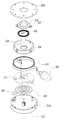
도 5는 본 발명의 일 실시예에 따른 음향기기(200)의 회동부재(230)의 분해사시도로서, 회동부재(230)는 회전축(232)을 구비한 휠케이스(231), 상기 휠케이스(231) 내부에 위치하며 상기 회전축(232)이 관통하는 개구부가 형성된 원통형의 휠(234), 휠(234)의 원통 내부에 위치하는 스파이럴 스프링(235), 음향케이블과 음향기판(236)의 접속을 유지하는 음향 브러시(247) 및 상기 음향케이블(245)을 하우징(220) 내부로 수납시 사용자가 누르는 수납버튼(233)을 포함한다.5 is an exploded perspective view of the pivoting
음향기판(236)은 음향신호를 음향케이블(245)에 전달하는 역할을 하며, 휠(234)의 회전에 관계없이 음향기판(236)과 음향케이블(245)가 접속되도록 음향케이블(234)과 음향기판(236) 사이에 음향 브러시(247)을 구비할 수 있다.The
음향기판(236)은 신호종류(예를 들면 좌측/우측 음향신호)에 반경이 다른 원형의 접속단자(236', 236")를 구비하고 상기 음향 브러시(247)는 음향기판(236)의 원형의 접속단자(236', 236")의 위를 움직이며 음향케이블(245)과 음향기판(236) 사이의 접속을 유지한다. 또는 음향케이블(245)이 회전하지 않는 회전축 중심을 통해 음향기판(236)과 연결되는 경우 음향 브러시(247)를 생략할 수 있다.The
휠케이스(231)는 내부에 회동부재(230)의 각 부재가 위치하며, 휠케이스(231)가 상기 하우징(220)에 결합하여 회동부재(230)가 고정된다. 휠케이스(231)의 중간에 돌출된 회전축(232)은 회동부재(230)의 회전의 중심이 되며, 상기 회전축(232)을 중심으로 휠(234)이 회전한다.The
휠케이스(231)는 도 4 및 도 5에 도시된 바와 같이 내부 공간을 구비한 원판 형상일 수 있고, 휠(234)이 상기 회전축(232)으로부터 이탈하지 않고 음향케이블(245)이 다른 부재들과 엉키지 않도록 인입출 될 수 있다면 휠케이스(231)를 생략하고 하우징(220)에 직접 회전축(232)을 형성할 수도 있다.The
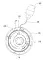
도 6은 본 발명의 일 실시예에 따른 음향기기(200)의 회동부재(230)의 휠케이스(231)를 개방한 상태를 도시한 평면도로서, 휠(234)은 휠케이스(231) 내측에 위치하며 회전축(232) 둘레를 감싸는 원통형의 부재로, 가운데 회전축(232)이 관통하는 개구부가 형성된다.6 is a plan view showing a state in which the
휠(234)의 외측에는 음향케이블(245)이 감기며, 음향케이블(245)이 제1 방향으로 감겨져 있을 때, 음향케이블(245)이 풀릴 때 휠(234)은 제1 방향으로 회전하고 음향케이블(245)을 휠(234)의 외측에 감기 위해서 휠(234)은 제2 방향으로 회전한다.When the
도 6을 참조하면 본 실시예에서는 음향케이블(245)은 반시계방향(제1 방향)으로 감겨져 있고, 리시버(240)가 인출되면 음향케이블(245)이 휠(234)을 반시계방향(제1 방향)으로 회전시키고 휠(234)이 시계방향(제2 방향)으로 회전하면 휠(234)의 외측에 음향케이블(245)이 권취되어 음향케이블(245)이 하우징(220) 내부로 수납된다. 본 실시예에서 제1 방향은 반시계방향이고 제2 방향은 시계방향이나 그 반대의 경우도 가능하다.6, the
휠(234)의 원통의 내측에 스파이럴 스프링(235)과 수납 버튼이 위치할 수 있다. 도 7은 본 발명의 일 실시예에 따른 음향기기(200)의 회동부재(230)의 단면도로서, 도 7에 도시된 바와 같이 수납버튼(233)과 스파이럴 스프링(235)은 회전축(232) 방향으로 중첩되지 않는다.A
스파이럴 스프링(235)은 나선 형상의 판스프링으로 감긴 방향의 반대 방향으로 힘을 인가하면 원래 감긴 형태로 복원하기 위해 감긴 방향으로 탄성력을 제공한다. 도 6을 참조하면 본 실시예의 스파이럴 스프링(235)은 중앙부터 시계방향으로 돌면서 감겨져 있어 반시계방향의 힘에 대해 시계방향의 탄성력을 인가한다.When the
사용자가 리시버(240)를 당겨 음향케이블(245)을 인출시 휠(234)이 반시계방향으로 돌면 스파이럴 스프링(235)의 감긴 회수가 줄어들면서 시계방향으로 휠(234)을 회전시키려는 탄성력을 제공하여 휠(234)의 외측에 음향케이블(245)을 감는다.When the user pulls the
도 8은 본 발명의 일 실시예에 따른 음향기기(200)의 회동부재(230)의 회전축(232)을 도시한 사시도로서 회전축(232)은 상기 스파이럴 스프링(235)이 고정되도록 홈이 형성될 수 있다. 스파이럴 스프링(235)의 타단이 상기 홈에 끼워져 타단은 회전하지 않고 회전축(232)에 고정될 수 있다.8 is a perspective view illustrating the
수납버튼(233)은 휠(234)의 원통 내부에 위치하고 외측에 돌출된 스토퍼(237)를 구비한다. 스토퍼(237)는 휠(234)의 내측에서 돌출된 걸림돌기(238)와 맞닿도록 돌출되어 있으며, 휠(234)의 회전방향에 따라 걸림돌기(238)와 맞닿아 휠(234)의 회전을 제한하거나 걸림돌기(238)에 형성된 경사면을 따라 이동하며 휠(234)의 회전을 허용한다.The
수납버튼(233)은 휠(234)의 원통 내측에 위치하나 휠(234)과 직접 결합하지 않고 회전축(232)과 결합하여 회전축(232) 방향으로 수직운동을 한다. 수납버튼(233)은 도 7 및 도 4에 도시된 바와 같이 하우징(220)의 외측으로 돌출되어 사용자가 상기 수납버튼(233)을 누르면 상기 수납버튼(233)은 제3 방향으로 이동한다.The
회전축(232)에는 버튼홀이 형성되어 상기 개구부에 수납버튼(233)의 하단에서 돌출된 버튼돌기(2333)가 삽입되어 버튼홀(232a)을 따라 상기 버튼돌기(2333)가 인입출되며 회전축(232) 방향으로 수납버튼(233)이 이동할 수 있다.A button hole is formed in the
사용자가 하우징(220) 외측에 돌출된 탑버튼(2331)을 제3 방향으로 누르면 수납버튼(233)은 하우징(220) 내측으로 인입되며, 사용자가 힘을 제거하면 다시 원래 위치로 복원되도록 수납버튼(233)을 하우징(220) 외측으로 밀어내는 제4 제공하는 방향의 힘을 코일스프링(2334)을 구비할 수 있다. 도 7에서 도면 상으로 제3 방향은 하측방향이고 제4 방향은 상측방향이다.When the user pushes the
코일스프링(2334)의 일단은 버튼홀의 내측단부 또는 버튼홀이 내측에 돌출된 지지부에 닿고 타단은 수납버튼(233)에 결합하여 수납버튼(233)의 탑버튼이 하우징(220) 바깥쪽으로 돌출되도록 제 4 방향으로 힘을 가한다.One end of the
이때 수납버튼(233)이 하우징(220)에 형성된 기구부에서 이탈되지 않도록 하우징(220)의 개구부의 내측에서 탑버튼 둘레로 연장된 날개부를 더 포함할 수 있다. 이때, 휠(234)은 걸림돌기(238)를 제외하고 상기 날개부 및 스토퍼(237)와 닿지 않도록 원통 가운데의 개구부의 상부는 넓게 형성한다. 하부는 스파이럴 스프링(235)을 지지하기 위해 상부보다 더 좁게 형성할 수 있다.At this time, the
이하에서는 휠(234)의 회전방향에 따라 스토퍼(237)가 휠(234)의 회전을 어떻게 제어하는지 도 9 및 도 10을 참조하여 구체적으로 살펴보도록 한다.Hereinafter, how the
도 9 및 도 10은 본 발명의 일 실시예에 따른 음향기기(200)의 음향케이블(245)이 휠(234)에서 풀릴 때 회동부재(230)의 스토퍼(237)와 걸림돌기(238) 부분을 도시한 도면이며, 도 9는 회전축(232) 방향으로 바라본 평면도이고, 도 10은 회전축(232)에서 걸림돌기(238) 방향을 바라본 도면이다.9 and 10 show a state in which the
본 실시예에서는 음향케이블(245)이 제1 방향(도면상 반시계방향)으로 감겨있고, 스파이럴 스프링(235)도 제1 방향으로 감긴 나선형상이다. 걸림돌기(238)는 중심에서 제1 방향(반시계방향)의 측면(2381)과 제2 방향(시계방향)의 측면(2382)을 갖으며, 제1 방향의 측면(2381)은 경사면을 포함하고, 제2 방향의 측면(2382)은 수직면을 포함한다.In this embodiment, the
제1 방향의 경사면(2381)은 결합돌기의 회전축(232) 방향 두께가 제1 방향 단부로 갈수록 얇아지며, 경사면(2381)은 하우징(220)의 내측면을 향하는 면과 반대편인 제3 방향(도 10에서 하측)에 형성된다.The
음향케이블(245)이 풀릴 때에 휠(234)이 제1 방향(반시계방향)으로 회전하므로 도 9에 도시된 바와 같이 스토퍼(237)는 걸림돌기(238)의 제1 방향 측면(2381)과 맞닿게 된다. 걸림돌기(238)의 제1 방향은 경사면을 포함하므로 도 10에 도시된 바와 같이 스토퍼(237)는 걸림돌기(238)의 경사면을 따라 회전축(232)과 나란한 제3 방향으로 이동한다.9, since the
도 10의 (b)와 같이 휠(234)이 회전시 걸림돌기(238)의 경사면이 스토퍼(237)를 제3 방향으로 누르는 힘을 제공하고 수납버튼(233)과 스토퍼(237)는 제3 방향으로 코일스프링(2334)을 압축시키며 이동한다. 걸림돌기(238)가 스토퍼(237)와 중첩되는 구간이 지나가면 도 10의 (d)와 같이 스토퍼(237)는 제4 방향으로 이동하여 원래 위치로 복원한다.10 (b), when the
도 11은 본 발명의 일 실시예에 따른 음향기기(200)의 음향케이블(245)이 휠(234)에 감길 때 회동부재(230)의 스토퍼(237)와 걸림돌기(238) 부분을 도시한 도면이다. 사용자가 음향케이블(245)을 당기던 것을 중단하면, 스파이럴 스프링(235)의 탄성력에 의해 휠(234)이 제2 방향으로 회전하는 힘을 받게 된다. 도 11의 (a)에 도시된 바와 같이 제2 방향(시계방향)으로 휠(234)이 도는 경우 스토퍼(237)와 걸림돌기(238)의 제2 방향의 측면(2382)과 맞닿게 된다.11 shows a portion of the
도 11의 (b)에 도시된 바와 같이 걸림돌기(238)의 제2 방향의 측면(2382)은 수직면을 포함하므로 스토퍼(237)가 제1 방향의 측면(2381)과 맞닿은 경우와 달리 수납버튼(233)이 제3 방향으로 이동하지 않고 제2 방향의 측면(2382)과 맞닿은 상태로 유지되어 휠(234)의 회전을 제한한다.The
따라서 사용자가 음향케이블(245)을 당겨서 음향케이블(245)을 하우징(220)에서 인출한 이후에 음향케이블(245)을 놓더라도 다시 하우징(220)으로 인입되지 않고 인출된 상태가 고정될 수 있다.Therefore, even if the user pulls the
도 12는 본 발명의 일 실시예에 따른 음향기기(200)의 회동부재(230)의 수납버튼(233)이 눌린 경우를 도시한 단면도이다. 사용자가 음향케이블(245)을 하우징(220) 내부로 수납하고자 할 때에는 상기 스토퍼(237)와 걸림돌기(238)의 제2 방향의 측면(2382)이 맞닿은 상태를 해제해야 하는 바, 강제로 수납버튼(233)을 제3 방향으로 사용자가 누르면 걸림돌기(238)와 스토퍼(237)가 회전축(232) 방향으로 다른 높이에 위치하므로 걸림돌기(238)가 스토퍼(237)의 방해를 받지 않고 휠(234)이 회전할 수 있다.FIG. 12 is a sectional view showing a case in which the
휠(234)은 스파이럴 스프링(235)의 탄성에 따라 제2 방향으로 회전하며 음향케이블(245)을 휠(234)의 외측에 감아 음향케이블(245)이 하우징(220) 내부로 수납될 수 있다.The
이상에서 살펴본 음향기기(200)는 사용자에 목에 걸어 사용하는 밴드를 구비한 무선음향기기(200)에 대해 설명하였으나, 본 발명의 특징은 하우징(220)에서 연장되어 리시버(240)에 연결된 음향케이블(245)을 상기 하우징(220)에 수납하는 구조에 있는 바, 사용자의 목에 착용하는 밴드(210)를 포함하는 음향기기(200) 이외에 다양한 휴대용 음향기기(200)에 적용 가능하고 무선통신부(255)가 없는 음향기기(200)에도 적용 가능하다.Although the present invention has been described with respect to a wireless
이상에서 살펴본 바와 같이 본 발명의 적어도 일 실시예에 따르면, 원형의 회동모듈 하나에 인입 및 인출시 회동모듈의 회전을 제어하는 스토퍼까지 구비할 수 있어, 구조가 단순하고 공간활용도를 높일 수 있다.As described above, according to at least one embodiment of the present invention, a circular rotating module can be provided with a stopper for controlling the rotation of the rotating module at the time of pulling-in and pulling out, so that the structure is simple and space utilization can be improved.
상기의 상세한 설명은 모든 면에서 제한적으로 해석되어서는 아니되고 예시적인 것으로 고려되어야 한다. 본 발명의 범위는 첨부된 청구항의 합리적 해석에 의해 결정되어야 하고, 본 발명의 등가적 범위 내에서의 모든 변경은 본 발명의 범위에 포함된다.The foregoing detailed description should not be construed in all aspects as limiting and should be considered illustrative. The scope of the present invention should be determined by rational interpretation of the appended claims, and all changes within the scope of equivalents of the present invention are included in the scope of the present invention.
200: 음향기기210: 밴드
220: 하우징250: 인쇄회로기판
223: 제1 버튼224: 제2 버튼
225: 리시버 홀더226: 스위치
230: 회동부재231: 휠케이스
232: 회전축233: 수납버튼
2331: 탑버튼2332: 날개부
2333: 버튼돌기2334: 코일스프링
234: 휠235: 스파이럴 스프링
236: 음향기판237: 스토퍼
238: 걸림돌기2381: 제1 방향 측면
2382: 제2 방향 측면240: 리시버
245: 음향케이블257: 전원공급부
250: 제어부255: 무선통신부200: sound device 210: band
220: housing 250: printed circuit board
223: first button 224: second button
225: receiver holder 226: switch
230: tiltable member 231: wheel case
232: rotation shaft 233: storage button
2331: Tobbert 2332:
2333: Button projection 2334: Coil spring
234: Wheel 235: Spiral spring
236: Acoustic Substrate 237: Stopper
238: locking protrusion 2381: first direction side surface
2382: second direction side 240: receiver
245: acoustic cable 257: power supply
250: control unit 255: wireless communication unit
Claims (10)
Translated fromKorean상기 하우징의 일측에 위치하며 상기 내부공간과 연결되는 케이블홀이 형성된 리시버 홀더;
상기 리시버 홀더에 착탈가능한 리시버;
상기 하우징의 내부공간에 배치되며 회전축을 중심으로 회전하는 회동부재; 및
일단부는 상기 회동부재에 연결되고 상기 케이블홀을 통과하여 타단부는 상기 리시버에 연결되는 음향케이블을 포함하고,
상기 회동부재는,
상기 하우징에 움직이지 않게 고정된 회전축;
외측 둘레에 상기 음향케이블이 권취되며 중앙에 상기 회전축이 관통하는 개구부가 형성된 원통형의 휠;
상기 휠의 원통 내부에 위치하고, 일측은 상기 휠의 내측에 결합하며, 타측은 상기 회전축에 결합하는 스파이럴 스프링;
상기 휠의 내측에 돌출된 걸림돌기;
일측은 상기 휠의 원통 내부에 위치하고, 타측은 상기 하우징 외측으로 노출되며, 상기 회전축의 축방향으로 직선운동하는 수납버튼; 및
상기 수납버튼의 둘레에서 돌출되며, 상기 걸림돌기와 맞닿는 스토퍼를 포함하는 음향기기.A housing including an inner space;
A receiver holder disposed at one side of the housing and having a cable hole connected to the inner space;
A receiver detachable from the receiver holder;
A pivoting member disposed in the inner space of the housing and rotating about a rotation axis; And
And an acoustic cable, one end of which is connected to the tiltable member and the other end of which is connected to the receiver,
Wherein the tiltable member comprises:
A rotating shaft fixed to the housing so as not to move;
A cylindrical wheel in which the acoustic cable is wound around an outer periphery and an opening through which the rotary shaft passes is formed at the center;
A spiral spring located inside the cylinder of the wheel, one side of which is coupled to the inside of the wheel, and the other side of which is coupled to the rotation shaft;
A locking protrusion protruding from the inside of the wheel;
A storage button located on one side of the wheel cylinder and the other on the outside of the housing and linearly moving in the axial direction of the rotation shaft; And
And a stopper projecting from the periphery of the storage button and abutting against the locking projection.
상기 휠은 상기 리시버를 당기면 상기 음향케이블이 풀리면서 제1 방향으로 회전하고,
상기 스파이럴 스프링은 상기 제1 방향과 반대 방향인 제2 방향으로 탄성력을 인가하는 것을 특징으로 하는 음향기기.The method according to claim 1,
When the receiver pulls the wheel, the wheel rotates in the first direction while the acoustic cable is released,
Wherein the spiral spring applies an elastic force in a second direction opposite to the first direction.
상기 걸림돌기의 제2 방향 측면은 수직면을 포함하며,
상기 스토퍼는 상기 탄성력에 의해 상기 휠이 제2 방향으로 회전시 상기 수직면에 맞닿아 상기 휠의 회전을 제한하는 것을 특징으로 하는 음향기기.3. The method of claim 2,
Wherein the second direction side surface of the engaging projection includes a vertical surface,
Wherein the stopper abuts the vertical surface when the wheel is rotated in the second direction by the elastic force, thereby restricting rotation of the wheel.
상기 걸림돌기는 제1 방향 단부로 갈수록 두께가 얇아지는 경사면을 포함하며,
상기 경사면은 상기 휠이 제1 방향으로 회전시 상기 스토퍼를 상기 회전축과 나란한 제3 방향으로 가압하는 것을 특징으로 하는 음향기기.3. The method of claim 2,
Wherein the engaging protrusion includes an inclined surface that becomes thinner toward the first direction end portion,
Wherein the inclined surface presses the stopper in a third direction parallel to the rotation axis when the wheel rotates in the first direction.
상기 수납버튼과 상기 회전축의 사이에 개재된 코일 스프링을 더 포함하고,
상기 코일 스프링은 상기 수납버튼을 사용자가 제3 방향으로 누르면 반대 방향인 제 4 방향으로 복원하는 힘을 인가하는 것을 특징으로 하는 음향기기.The method according to claim 1,
Further comprising a coil spring interposed between the storage button and the rotation shaft,
Wherein the coil spring applies a force to restore the storage button in a fourth direction which is the opposite direction when the user pushes the storage button in the third direction.
상기 회전축에 형성된 버튼홀; 및
상기 수납버튼에서 돌출되어 상기 버튼홀에 삽입되는 버튼돌기를 더 포함하고,
상기 코일 스프링은 상기 버튼홀의 내측 단부 또는 상기 버튼홀에서 돌출된 지지부와 상기 버튼돌기 사이에 개재되는 것을 특징으로 하는 음향기기.6. The method of claim 5,
A button hole formed in the rotary shaft; And
Further comprising a button projection projecting from the receiving button and being inserted into the button hole,
Wherein the coil spring is interposed between an inner end of the buttonhole or a support protruding from the buttonhole and the button protrusion.
상기 수납버튼은
상기 하우징의 개구부를 통해 인입출되는 탑버튼; 및
상기 하우징 내부에서 상기 탑버튼의 외측으로 연장된 날개부를 포함하는 것을 특징으로 하는 음향기기.The method according to claim 1,
The storage button
A top button which is pulled out through an opening of the housing; And
And a wing extending from the inside of the housing to an outer side of the tobette.
상기 수납버튼 및 상기 스토퍼는 상기 스파이럴 스프링과 회전축 방향으로 중첩되지 않는 것을 특징으로 하는 음향기기.The method according to claim 1,
Wherein the storage button and the stopper are not overlapped with the spiral spring in the direction of the rotation axis.
상기 회전축에 형성된 고정홈을 더 포함하고, 상기 스파이럴 스프링의 타측은 상기 고정홈에 삽입되어 상기 회전축에 결합하는 것을 특징으로 하는 음향기기.The method according to claim 1,
Further comprising a fixing groove formed in the rotary shaft, and the other side of the spiral spring is inserted into the fixing groove and coupled to the rotary shaft.
상기 휠에서 상기 회전축의 축방향으로 상기 수납버튼과 반대방향에 위치하는 원형전극을 갖는 음향기판; 및
상기 음향케이블의 일단에서 연장되어 상기 원형전극과 접촉하는 단자 브러시를 더 포함하고,
상기 휠이 회전시 상기 단자 브러시는 상기 원형전극을 따라 이동하는 것을 특징으로 하는 음향기기.The method according to claim 1,
An acoustic substrate having a circular electrode located in an opposite direction to the storage button in the axial direction of the rotary shaft in the wheel; And
Further comprising a terminal brush extending from one end of the acoustic cable and contacting the circular electrode,
Wherein the terminal brush moves along the circular electrode when the wheel rotates.
Priority Applications (1)
| Application Number | Priority Date | Filing Date | Title |
|---|---|---|---|
| KR1020140145092AKR20160048452A (en) | 2014-10-24 | 2014-10-24 | Sound EQUIPMENT |
Applications Claiming Priority (1)
| Application Number | Priority Date | Filing Date | Title |
|---|---|---|---|
| KR1020140145092AKR20160048452A (en) | 2014-10-24 | 2014-10-24 | Sound EQUIPMENT |
Publications (1)
| Publication Number | Publication Date |
|---|---|
| KR20160048452Atrue KR20160048452A (en) | 2016-05-04 |
Family
ID=56021980
Family Applications (1)
| Application Number | Title | Priority Date | Filing Date |
|---|---|---|---|
| KR1020140145092AWithdrawnKR20160048452A (en) | 2014-10-24 | 2014-10-24 | Sound EQUIPMENT |
Country Status (1)
| Country | Link |
|---|---|
| KR (1) | KR20160048452A (en) |
Cited By (4)
| Publication number | Priority date | Publication date | Assignee | Title |
|---|---|---|---|---|
| CN109121036A (en)* | 2018-10-20 | 2019-01-01 | 嘉兴市华阳电器有限公司 | A kind of adjustable type has the multimedia earphone of safeguard structure |
| US10244305B2 (en) | 2017-08-03 | 2019-03-26 | Lg Electronics Inc. | Portable sound device |
| US10306351B2 (en) | 2017-08-03 | 2019-05-28 | Lg Electronics Inc. | Portable sound device |
| WO2019117496A1 (en)* | 2017-12-12 | 2019-06-20 | 엘지전자 주식회사 | Portable acoustic device |
- 2014
- 2014-10-24KRKR1020140145092Apatent/KR20160048452A/ennot_activeWithdrawn
Cited By (5)
| Publication number | Priority date | Publication date | Assignee | Title |
|---|---|---|---|---|
| US10244305B2 (en) | 2017-08-03 | 2019-03-26 | Lg Electronics Inc. | Portable sound device |
| US10306351B2 (en) | 2017-08-03 | 2019-05-28 | Lg Electronics Inc. | Portable sound device |
| WO2019117496A1 (en)* | 2017-12-12 | 2019-06-20 | 엘지전자 주식회사 | Portable acoustic device |
| CN109121036A (en)* | 2018-10-20 | 2019-01-01 | 嘉兴市华阳电器有限公司 | A kind of adjustable type has the multimedia earphone of safeguard structure |
| CN109121036B (en)* | 2018-10-20 | 2024-12-20 | 嘉兴市华阳电器有限公司 | Adjustable multimedia earphone with protective structure |
Similar Documents
| Publication | Publication Date | Title |
|---|---|---|
| KR101507869B1 (en) | Wireless sound equipment | |
| US9913016B2 (en) | Wireless sound equipment | |
| US8295770B2 (en) | Electrical accessory and method of providing same | |
| US10306351B2 (en) | Portable sound device | |
| US10491983B2 (en) | Portable sound equipment | |
| KR20160029524A (en) | Electronic device and system comprising it | |
| KR20160048452A (en) | Sound EQUIPMENT | |
| KR20170011320A (en) | Electronic Device | |
| KR101943329B1 (en) | Portable sound equipment | |
| WO2020155695A1 (en) | Wire control box for wireless earphone and wireless earphone | |
| KR102104897B1 (en) | Wireless sound equipment | |
| US8059854B2 (en) | Earphone | |
| KR101637369B1 (en) | Wireless sound equipment | |
| KR101615240B1 (en) | Wireless sound equipment | |
| EP3439321B1 (en) | Portable sound device | |
| KR20190019546A (en) | Portable sound equipment | |
| KR20190069755A (en) | Portable sound equipment | |
| KR20170013572A (en) | Electronic Device | |
| CN209981651U (en) | Wire control box for wireless earphone and wireless earphone | |
| KR101570298B1 (en) | Headset | |
| KR20150007584A (en) | Band assembly for smart watch having band touch sensor | |
| KR20190014978A (en) | Rotation module and portable sound equipment | |
| KR20190022138A (en) | Portable sound equipment | |
| KR20180080669A (en) | Portable sound equipment | |
| KR20190014980A (en) | Portable sound equipment |
Legal Events
| Date | Code | Title | Description |
|---|---|---|---|
| PA0109 | Patent application | Patent event code:PA01091R01D Comment text:Patent Application Patent event date:20141024 | |
| PG1501 | Laying open of application | ||
| PC1203 | Withdrawal of no request for examination | ||
| WITN | Application deemed withdrawn, e.g. because no request for examination was filed or no examination fee was paid |