KR20160041770A - Electronic device having a touch sensor and driving method thereof - Google Patents
Electronic device having a touch sensor and driving method thereofDownload PDFInfo
- Publication number
- KR20160041770A KR20160041770AKR1020150136834AKR20150136834AKR20160041770AKR 20160041770 AKR20160041770 AKR 20160041770AKR 1020150136834 AKR1020150136834 AKR 1020150136834AKR 20150136834 AKR20150136834 AKR 20150136834AKR 20160041770 AKR20160041770 AKR 20160041770A
- Authority
- KR
- South Korea
- Prior art keywords
- touch
- touch screen
- display panel
- sensing method
- mode
- Prior art date
- Legal status (The legal status is an assumption and is not a legal conclusion. Google has not performed a legal analysis and makes no representation as to the accuracy of the status listed.)
- Granted
Links
Images


Classifications
- G—PHYSICS
- G06—COMPUTING OR CALCULATING; COUNTING
- G06F—ELECTRIC DIGITAL DATA PROCESSING
- G06F3/00—Input arrangements for transferring data to be processed into a form capable of being handled by the computer; Output arrangements for transferring data from processing unit to output unit, e.g. interface arrangements
- G06F3/01—Input arrangements or combined input and output arrangements for interaction between user and computer
- G06F3/03—Arrangements for converting the position or the displacement of a member into a coded form
- G06F3/041—Digitisers, e.g. for touch screens or touch pads, characterised by the transducing means
- G06F3/0412—Digitisers structurally integrated in a display
Landscapes
- Engineering & Computer Science (AREA)
- General Engineering & Computer Science (AREA)
- Theoretical Computer Science (AREA)
- Position Input By Displaying (AREA)
- Control Of Indicators Other Than Cathode Ray Tubes (AREA)
- Human Computer Interaction (AREA)
- Physics & Mathematics (AREA)
- General Physics & Mathematics (AREA)
- Liquid Crystal Display Device Control (AREA)
- Switches That Are Operated By Magnetic Or Electric Fields (AREA)
Abstract
Description
Translated fromKorean본 발명은 터치 센서를 갖는 전자장치와 이의 구동 방법에 관한 것이다.The present invention relates to an electronic device having a touch sensor and a driving method thereof.
각종 전자장치 예컨대 가전기기나 휴대용 정보기기는 경량화, 슬림화 추세에 따라 사용자의 입력 수단이 버튼형 스위치에서 터치 센서로 대체되고 있다. 이에 따라, 최근 출시되는 표시장치 등과 같은 전자장치는 터치 센서(또는 터치 스크린)를 갖는다.Various electronic devices, such as household appliances and portable information devices, have been replaced by touch sensors in a button-type switch in accordance with the trend of weight reduction and slimness. Accordingly, an electronic device such as a display device or the like that has recently been introduced has a touch sensor (or a touch screen).
터치 센서는 스마트 폰과 같은 휴대용 정보기기에 필수적으로 채택되고 있으며, 노트북 컴퓨터, 컴퓨터 모니터, 가전 제품 등에 확대 적용되고 있다. 최근에는 터치 센서를 표시패널의 픽셀 어레이에 내장하는 기술(이하, "인셀 터치 센서(In-cell touch sensor)"라 함)이 제안되고 있다.Touch sensors are essential for portable information devices such as smart phones, and are being widely applied to notebook computers, computer monitors, and home appliances. Recently, a technology (hereinafter referred to as "In-cell touch sensor") in which a touch sensor is embedded in a pixel array of a display panel has been proposed.
인셀 터치 센서 기술은 표시패널의 두께 증가 없이 표시패널에 터치 센서들을 설치할 수 있다. 인셀 터치 센서를 갖는 전자장치는 픽셀들과 터치 센서들의 커플링(Coupling)으로 인한 상호 영향을 줄이기 위하여, 픽셀들을 구동하는 기간("디스플레이 구동 기간"이라고도 함)과 터치 센서들을 구동하는 기간("터치 스크린 구동 기간"이라고도 함)을 시분할 한다.Incelel touch sensor technology can install touch sensors on the display panel without increasing the thickness of the display panel. An electronic device having an in-cell touch sensor includes a period for driving pixels (also referred to as a " display driving period ") and a period for driving touch sensors (referred to as a" Quot; touch screen driving period ").
인셀 터치 센서 기술은 표시패널의 픽셀들에 연결된 전극을 터치 센서들의 전극으로 활용한다. 예를 들어, 인셀 터치 센서 기술은 액정표시장치의 픽셀들에 공통전압을 공급하기 위한 공통 전극을 분할하여 터치 센서들의 전극으로 활용하는 예가 제안되고 있다.The Insel touch sensor technology utilizes the electrodes connected to the pixels of the display panel as the electrodes of the touch sensors. For example, in the case of the in-line touch sensor technology, an example has been proposed in which a common electrode for supplying a common voltage to pixels of a liquid crystal display is divided and used as electrodes of touch sensors.
아울러, 인셀 터치 센서 기술 분야에는 표시장치를 사용하지 않을 때 슬립 모드(또는 휴지 모드)로 돌입하는 기능이 제안된바 있다. 슬립 모드는 표시장치를 사용하지 않으면 표시패널 등을 휴지시키는 방식으로 장치의 소비전력을 낮춘다. 하지만, 종래에 제안된 슬립 모드 방식은 소비전력을 저감하기 위한 연구를 지속해야 할 필요성이 있다.In addition, a function of entering the sleep mode (or the idle mode) when the display device is not used has been proposed in the in-cell touch sensor technology. In the sleep mode, the power consumption of the device is lowered by stopping the display panel or the like when the display device is not used. However, in the conventional sleep mode method, there is a need to continue studies for reducing power consumption.
상술한 배경기술의 문제점을 해결하기 위한 본 발명은 특정 모드(예컨대, 슬립 모드)를 수행하는 동안 구동의 안정성 및 신뢰성을 유지하면서 소비전력을 낮출 수 있는 터치 센서를 갖는 전자장치와 이의 구동방법을 제공하는 것이다.In order to solve the above problems, the present invention provides an electronic device having a touch sensor capable of lowering power consumption while maintaining stability and reliability of driving during a specific mode (e.g., sleep mode), and a driving method thereof .
상술한 과제 해결 수단으로 본 발명은 표시패널, 터치 스크린 및 터치 스크린 구동회로를 포함하는 터치 센서를 갖는 전자장치를 제공한다. 표시패널은 영상을 표시한다. 터치 스크린은 표시패널에 위치하는 전극으로 구성된다. 터치 스크린 구동회로는 터치 스크린을 구동하되, 표시패널의 표시 모드에 대응하여 터치 스크린을 제1터치 센싱 방식으로 구동하거나 제1터치 센싱 방식과 다른 제2터치 센싱 방식으로 구동하도록 센싱 모드를 전환한다.The present invention provides an electronic device having a touch sensor including a display panel, a touch screen, and a touch screen driving circuit. The display panel displays the image. The touch screen is composed of electrodes positioned on the display panel. The touch screen driving circuit drives the touch screen in accordance with the display mode of the display panel, and switches the sensing mode to drive the touch screen by the first touch sensing method or by the second touch sensing method different from the first touch sensing method .
터치 스크린 구동회로는 표시패널의 표시 모드에 대응하여 셀프 터치 센싱 방식으로 모드가 전환되거나 뮤추얼 터치 센싱 방식으로 모드가 전환될 수 있다.The touch screen drive circuit may be switched to a self-touch sensing mode or a mutual touch sensing mode according to the display mode of the display panel.
터치 스크린 구동회로는 표시패널이 영상을 표시하는 노말 모드 상태일 때 셀프 터치 센싱 방식으로 터치 스크린을 구동하고, 표시패널이 영상을 비표시하는 슬립 모드 상태일 때 뮤추얼 터치 센싱 방식으로 터치 스크린을 구동할 수 있다.The touch screen drive circuit drives the touch screen by the self-touch sensing method when the display panel is in the normal mode displaying the image, and the touch screen is driven by the mutual touch sensing method when the display panel is in the sleep mode can do.
터치 스크린 구동회로가 제2터치 센싱 방식으로 터치 스크린을 구동할 경우, 터치 스크린의 블록(또는 포인트) 형태로 구성된 전극들은 터치 스크린의 제1방향에 대하여 적어도 하나의 라인씩 쇼트될 수 있다.When the touch screen driving circuit drives the touch screen by the second touch sensing method, the electrodes configured in a block (or point) form of the touch screen may be shorted by at least one line in the first direction of the touch screen.
터치 스크린 구동회로가 제2터치 센싱 방식으로 상기 터치 스크린을 구동할 경우, 터치 스크린의 블록(또는 포인트) 형태로 구성된 전극들은 터치 스크린의 제1방향에 대하여 하나의 라인, 제1방향에 대하여 N개의 라인 또는 모두 쇼트될 수 있다.When the touch screen driving circuit drives the touch screen by the second touch sensing method, the electrodes formed in the form of a block (or point) of the touch screen include one line with respect to the first direction of the touch screen, N Lines or both can be shorted.
다른 측면에서 본 발명은 표시패널, 터치 스크린 및 터치 스크린 구동회로를 포함하는 터치 센서를 갖는 전자장치를 제공한다. 표시패널은 영상을 표시한다. 터치 스크린은 표시패널에 위치하는 전극으로 구성된다. 터치 스크린 구동회로는 터치 스크린의 블록(또는 포인트) 형태로 구성된 전극들이 터치 스크린의 제1방향에 대하여 적어도 하나의 라인씩 쇼트되도록 제어한다.In another aspect, the present invention provides an electronic device having a touch sensor including a display panel, a touch screen, and a touch screen drive circuit. The display panel displays the image. The touch screen is composed of electrodes positioned on the display panel. The touch screen driver circuit controls the electrodes formed in the block (or point) form of the touch screen to be shorted by at least one line in the first direction of the touch screen.
또 다른 측면에서 본 발명은 터치 센서를 갖는 전자장치의 구동방법을 제공한다. 터치 센서를 갖는 전자장치의 구동방법은 표시패널에 영상을 표시하고 제1터치 센싱 방식으로 표시패널에 내장된 터치 스크린을 구동하는 단계; 표시패널에 입력 유무를 판별하고, 입력이 미존재하면 슬립 모드로 돌입하고, 표시패널에 영상을 비표시하고 제1터치 센싱 방식과 다른 제2터치 센싱 방식으로 터치 스크린을 구동하는 단계; 및 표시패널을 터치하는 노크온이 발생하면 슬립 모드를 해제하고 표시패널에 영상을 표시하고 제2터치 센싱 방식에서 상기 제1터치 센싱 방식으로 센싱 모드를 전환하는 단계를 포함한다.In another aspect, the present invention provides a method of driving an electronic device having a touch sensor. A method of driving an electronic device having a touch sensor includes displaying an image on a display panel and driving a touch screen built in the display panel using a first touch sensing method; Driving the touch screen by a second touch sensing method different from the first touch sensing method, entering the sleep mode when no input is present, displaying an image on the display panel, and driving the touch screen. And when the knock-on operation for touching the display panel occurs, the sleep mode is canceled and the image is displayed on the display panel, and the sensing mode is switched from the second touch sensing mode to the first touch sensing mode.
제1터치 센싱 방식은 셀프 터치 센싱 방식으로 선택되고, 제2터치 센싱 방식은 뮤추얼 터치 센싱 방식으로 선택될 수 있다.The first touch sensing method may be selected by the self-touch sensing method, and the second touch sensing method may be selected by the mutual touch sensing method.
제2터치 센싱 방식으로 상기 터치 스크린을 구동할 경우, 터치 스크린의 블록(또는 포인트) 형태로 구성된 전극들은 터치 스크린의 제1방향에 대하여 하나의 라인, 제1방향에 대하여 N개의 라인 또는 모두 쇼트될 수 있다.When driving the touch screen by the second touch sensing method, the electrodes formed in the form of a block (or point) of the touch screen include one line with respect to the first direction of the touch screen, N lines with respect to the first direction, .
본 발명은 터치 센서를 갖는 전자장치가 특정 모드(예컨대, 슬립 모드)를 수행하는 동안 구동의 안정성 및 신뢰성을 유지하면서 소비전력을 낮출 수 있는 효과가 있다. 또한, 본 발명은 터치 센서를 갖는 전자장치를 인셀 터치 방식과 뮤추얼 터치 센싱 방식과 같이 센싱 방식을 전환할 수 있는 효과가 있다. 또한, 본 발명은 저전력 모드 구현하면서 터치 검출을 하기 위한 방법으로 터치 센서의 커패시터의 크기에 따른 포화 문제를 회피할 수 있는 효과가 있다.The present invention has the effect of lowering the power consumption while maintaining stability and reliability of driving while the electronic device having the touch sensor performs a specific mode (e.g., sleep mode). In addition, the present invention has an effect that the electronic device having the touch sensor can switch the sensing method such as the in-cell touch method and the mutual touch sensing method. In addition, the present invention has an effect of avoiding a saturation problem depending on the size of a capacitor of a touch sensor by performing touch detection while implementing a low power mode.
도 1은 본 발명의 제1실시예에 따른 표시장치의 구성을 개략적으로 보여 주는 블록도.
도 2는 터치 스크린의 터치 센서를 개략적으로 보여주는 예시도.
도 3은 공통전극으로 이루어진 터치 스크린을 보여주는 예시도.
도 4는 인셀 터치 방식의 시분할 구동 기술을 설명하기 위한 파형 예시도.
도 5는 표시장치의 저소비전력 구동 방식을 설명하기 위한 도면.
도 6은 종래에 제안된 센싱 방식을 개략적으로 설명하기 위한 도면.
도 7은 본 발명의 제1실시예에 따른 센싱 방식을 개략적으로 설명하기 위한 도면.
도 8은 본 발명의 제1실시예에 따른 표시장치의 구동방법을 설명하기 위한 흐름도.
도 9는 본 발명의 제1실시예를 구체화한 장치의 구성 예시도.
도 10은 노크온 모드에서 외곽 라인의 동작 특성을 보여주는 예시도.
도 11은 도 9에 도시된 제1라인의 구동 예시도.
도 12는 도 9에 도시된 제2라인의 구동 예시도.
도 13은 도 9에 도시된 제3라인의 구동 예시도.
도 14는 본 발명의 제2실시예에 따라 슬립 모드로 동작 시 블록 단위 센싱을 위한 터치 센서의 구성예시도.
도 15는 도 14의 블록 단위 센싱시 쇼트되는 영역의 예시도.1 is a block diagram schematically showing a configuration of a display device according to a first embodiment of the present invention;
FIG. 2 is an exemplary view schematically showing a touch sensor of a touch screen; FIG.
3 is an exemplary view showing a touch screen made up of common electrodes;
4 is a waveform diagram for explaining an in-cell touch type time division driving technique.
5 is a diagram for explaining a low power consumption driving method of the display apparatus;
6 is a diagram for schematically explaining a sensing method proposed in the related art;
7 is a schematic view for explaining a sensing method according to the first embodiment of the present invention.
8 is a flowchart for explaining a method of driving a display device according to the first embodiment of the present invention.
Fig. 9 is a diagram showing an example of the configuration of an apparatus embodying the first embodiment of the present invention. Fig.
10 is an exemplary diagram showing the operation characteristics of an outline line in the knock-on mode;
Fig. 11 is a driving example of the first line shown in Fig. 9; Fig.
Fig. 12 is a driving example of the second line shown in Fig. 9; Fig.
Fig. 13 is a driving example of the third line shown in Fig. 9; Fig.
FIG. 14 is a diagram illustrating a configuration example of a touch sensor for block-based sensing when operating in a sleep mode according to a second embodiment of the present invention; FIG.
Fig. 15 is an illustration of an area where a block is sensed in block sensing in Fig. 14; Fig.
이하, 본 발명의 실시를 위한 구체적인 내용을 첨부된 도면을 참조하여 설명한다.DETAILED DESCRIPTION OF THE PREFERRED EMBODIMENTS Hereinafter, embodiments of the present invention will be described in detail with reference to the accompanying drawings.
본 발명에 따른 터치 센서를 갖는 전자장치는 텔레비젼, 셋톱박스, 네비게이션, 영상 플레이어, 블루레이 플레이어, 개인용 컴퓨터(PC), 홈시어터 및 모바일폰 등으로 구현된다.An electronic device having a touch sensor according to the present invention is implemented as a television, a set-top box, a navigation device, a video player, a Blu-ray player, a personal computer (PC), a home theater and a mobile phone.
본 발명에 따른 터치 센서를 갖는 전자장치는 일례로 표시패널을 기반으로 구현된다. 표시패널은 액정표시패널, 유기발광표시패널, 전기영동표시패널, 플라즈마표시패널 등의 평판표시패널이 선택될 수 있으나 이에 한정되지 않는다. 다만, 이하의 설명에서는 설명의 편의를 위해 액정표시패널을 예로 설명한다.An electronic device having a touch sensor according to the present invention is implemented based on a display panel as an example. The display panel may be a flat panel display panel such as a liquid crystal display panel, an organic light emitting display panel, an electrophoretic display panel, or a plasma display panel, but is not limited thereto. However, in the following description, a liquid crystal display panel will be described as an example for convenience of explanation.
<제1실시예>≪
도 1은 본 발명의 제1실시예에 따른 표시장치의 구성을 개략적으로 보여 주는 블록도이고, 도 2는 터치 스크린의 터치 센서를 개략적으로 보여주는 예시도이며, 도 3은 공통전극으로 이루어진 터치 스크린을 보여주는 예시도이고, 도 4는 인셀 터치 방식의 시분할 구동 기술을 설명하기 위한 파형 예시도이다.FIG. 1 is a block diagram schematically showing a configuration of a display device according to a first embodiment of the present invention. FIG. 2 is an exemplary view schematically showing a touch sensor of a touch screen. FIG. 4 is a waveform diagram for explaining the time division driving technique of the in-cell touch method.
도 1에 도시된 바와 같이, 본 발명의 제1실시예에 따른 표시장치에는 타이밍 콘트롤러(20), 데이터 구동회로(12), 스캔 구동회로(14), 액정표시패널(DIS), 터치 스크린(TSP) 및 터치 스크린 구동회로(30)가 포함된다.1, the display device according to the first embodiment of the present invention includes a
타이밍 콘트롤러(20)는 호스트 시스템(미도시)으로부터 수직 동기신호(Vsync), 수평 동기신호(Hsync), 데이터 인에이블 신호(Data Enable, DE), 메인 클럭(MCLK) 등의 타이밍신호와 더불어 디지털 비디오 데이터(RGB)를 공급받고, 이를 기반으로 데이터 구동회로(12)와 스캔 구동회로(14)를 제어한다.The
타이밍 콘트롤러(20)는 게이트 스타트 펄스(Gate Start Pulse, GSP), 게이트 쉬프트 클럭(Gate Shift Clock) 및 게이트 출력 인에이블신호(Gate Output Enable, GOE) 등의 스캔 타이밍 제어신호를 기반으로 스캔 구동회로(14)를 제어한다. 타이밍 콘트롤러(20)는 소스 샘플링 클럭(Source Sampling Clock, SSC), 극성제어신호(Polarity, POL) 및 소스 출력 인에이블신호(Source Output Enable, SOE) 등의 데이터 타이밍 제어신호를 기반으로 데이터 구동회로(12)를 제어한다.The
데이터 구동회로(12)는 타이밍 콘트롤러(20)로부터 입력되는 디지털 비디오 데이터(RGB)를 아날로그 정극성/부극성 감마보상전압으로 변환하여 데이터전압을 생성한다. 데이터 구동회로(12)는 데이터라인들(D1~Dm)을 통해 데이터전압을 공급한다.The
스캔 구동회로(14)는 데이터전압에 동기되는 게이트펄스(또는 스캔펄스)를 순차적으로 생성한다. 스캔 구동회로(14)는 게이트라인들(G1~Gn)을 통해 게이트펄스를 공급한다.The
액정표시패널(DIS)은 스캔 구동회로(14)로부터 공급된 게이트펄스와 데이터 구동회로(12)로부터 공급된 데이터전압을 기반으로 영상을 표시한다. 액정표시패널(DIS)은 두 장의 기판 사이에 형성된 액정층을 포함한다. 액정표시패널(DIS)은 TN(Twisted Nematic) 모드, VA(Vertical Alignment) 모드, IPS(In Plane Switching) 모드, FFS(Fringe Field Switching) 모드 등 공지된 어떠한 액정 모드로도 구현될 수 있다.The liquid crystal display panel DIS displays an image based on the gate pulse supplied from the
액정표시패널(DIS)의 서브 픽셀들은 데이터라인들(D1~Dm, m은 2 이상의 정수)과 게이트라인들(G1~Gn, n은 2 이상의 정수)에 의해 정의된다. 하나의 서브 픽셀은 데이터라인과 게이트라인의 교차부들에 형성된 TFT(Thin Film Transistor), 데이터전압을 충전하는 화소전극, 화소전극에 접속되어 액정셀의 전압을 유지시키기 위한 스토리지 커패시터(Storage Capacitor, Cst) 등을 포함한다.The subpixels of the liquid crystal display panel DIS are defined by data lines (D1 to Dm, m is an integer of 2 or more) and gate lines (G1 to Gn, n is an integer of 2 or more). One subpixel includes a TFT (Thin Film Transistor) formed at the intersections of the data line and the gate line, a pixel electrode for charging the data voltage, a storage capacitor Cst connected to the pixel electrode for maintaining the voltage of the liquid crystal cell ) And the like.
액정표시패널(DIS)의 상부 기판에는 블랙매트릭스, 컬러필터 등이 형성된다. 액정표시패널(DIS)의 하부 기판에는 박막 트랜지스터, 화소전극 및 공통전극 등이 형성된다. 액정표시패널(DIS)은 COT(Color filter On TFT) 구조로 구현될 수 있다. 이 경우, 블랙매트릭스와 컬러필터는 액정표시패널(DIS)의 하부 기판에 형성될 수 있다.A black matrix, a color filter, and the like are formed on the upper substrate of the liquid crystal display panel DIS. A thin film transistor, a pixel electrode, a common electrode, and the like are formed on a lower substrate of the liquid crystal display panel DIS. The liquid crystal display panel (DIS) can be implemented as a COT (Color Filter On TFT) structure. In this case, the black matrix and the color filter may be formed on the lower substrate of the liquid crystal display panel DIS.
공통전압이 공급되는 공통전극은 액정표시패널(DIS)의 상부 기판이나 하부 기판에 형성될 수 있다. 액정표시패널(DIS)의 상부 기판과 하부 기판에는 각각 편광판이 부착되고 액정과 접하는 내면에 액정의 프리틸트각을 설정하기 위한 배향막이 형성된다.The common electrode to which the common voltage is supplied may be formed on the upper substrate or the lower substrate of the liquid crystal display panel DIS. On the upper substrate and the lower substrate of the liquid crystal display panel DIS, a polarizing plate is attached, and an alignment film for forming a pre-tilt angle of the liquid crystal is formed on the inner surface in contact with the liquid crystal.
액정표시패널(DIS)의 상부 기판과 하부 기판 사이에는 액정셀의 셀갭(Cell gap)을 유지하기 위한 컬럼 스페이서가 형성된다. 액정표시패널(DIS)의 하부 편광판의 배면 아래에는 백라이트 유닛이 배치된다. 백라이트 유닛은 에지형(edge type) 또는 직하형(Direct type) 등으로 구현되어 액정표시패널(DIS)에 광을 제공한다.A column spacer for maintaining a cell gap of the liquid crystal cell is formed between the upper substrate and the lower substrate of the liquid crystal display panel DIS. A backlight unit is disposed below the bottom surface of the lower polarizer plate of the liquid crystal display panel DIS. The backlight unit is implemented as an edge type or a direct type to provide light to the liquid crystal display panel DIS.
터치 스크린 구동회로(30)는 터치 스크린(TSP)을 이용하여 터치의 유무 및 위치를 센싱한다. 터치 스크린 구동회로(30)에는 터치 센서를 구동하기 위한 구동전압을 생성하는 구동회로와 터치 센서를 센싱하고 터치의 유무 및 좌표 정보 등을 검출하기 위한 데이터를 생성하는 센싱회로가 포함된다. 터치 스크린 구동회로(30)의 구동회로와 센싱회로는 하나의 집적회로(IC) 형태로 형성되거나 기능별로 구분되어 분리될 수 있다.The touch
터치 스크린 구동회로(30)는 액정표시패널(DIS)과 접속되는 외부 기판 상에 형성된다. 터치 스크린 구동회로(30)는 센싱라인들(L1~Li, i는 양의 정수)을 통해 터치 스크린(TSP)에 연결된다. 터치 스크린 구동회로(30)는 터치 스크린(TSP)에 형성된 터치 센서들 간의 정전용량 편차를 기반으로 터치의 유무 및 위치를 센싱한다.The touch
사용자의 손가락이 접촉된 위치와 비접촉된 위치 간에는 정전용량의 편차가 발생하는데, 터치 스크린 구동회로(30)는 이 정전용량을 감지하는 방식으로 터치의 유무 및 위치를 센싱한다. 터치 스크린 구동회로(30)는 터치의 유무 및 위치에 대한 터치 데이터(HIDxy)를 생성하고 이를 호스트 시스템(미도시)으로 전달한다.A capacitance variation occurs between a position where the user's finger is touched and a non-contact position. The touch
도 2에 도시된 바와 같이, 터치 스크린(TSP)은 액정표시패널(DIS)의 표시영역(AA)에 인셀 셀프 터치(in-cell self touch)(이하 셀프 터치로 약기함) 방식으로 내장되도록 구현된다. 셀프 터치 센싱 방식의 터치 스크린(TSP)은 액정표시패널(DIS)의 내부에 형성된 전극 등에 의해 블록(또는 포인트) 형태로 구성된 전극을 터치 센서로 이용한다.2, the touch screen TSP is embedded in the display area AA of the liquid crystal display panel DIS in an in-cell self touch (hereinafter referred to as self-touch) do. A touch screen (TSP) of the self-touch sensing type uses an electrode formed in a block (or point) shape by an electrode or the like formed inside the liquid crystal display panel DIS as a touch sensor.
액정표시패널(DIS)의 표시영역(AA)에 형성된 "C1, C2, C3, C4"는 터치 센서(또는 터치 센서블록)를 의미하고, "L1, L2, L3, L4"는 터치 센서에 연결된 센싱라인을 의미한다. 이하에서는 공통전극으로 터치 센서를 구성하는 예를 기준으로 설명한다."C1, C2, C3, C4" formed in the display area AA of the liquid crystal display panel DIS means a touch sensor (or touch sensor block), and "L1, L2, L3, L4" Sensing line. Hereinafter, an example in which the touch sensor is configured as a common electrode will be described.
도 3에 도시된 바와 같이, 셀프 터치 센싱 방식의 터치 스크린(TSP)은 액정표시패널(DIS)의 내부에 형성된 제M개(M은 4 이상 정수)의 서브 픽셀(예컨대, 가로 32개의 서브 픽셀 * 세로 32개의 서브 픽셀)에 포함된 공통전극들(COM)이 하나의 터치 센서를 이루게 된다. 즉, 터치 센서들(C1, C2, C3, C4)은 액정표시패널(DIS) 상에서 분리 형성된 공통전극들(COM)에 의해 정의된다.3, a touch screen (TSP) of a self-touch sensing type includes M (M is an integer of 4 or more) sub-pixels (for example, 32 sub-pixels in the horizontal direction) formed in the liquid crystal display panel DIS * 32 sub-pixels in the vertical direction) constitute one touch sensor. That is, the touch sensors C1, C2, C3, and C4 are defined by the common electrodes COM formed separately on the liquid crystal display panel DIS.
도 1 내지 도 3에 도시된 바와 같이, 터치 스크린 구동회로(30)는 셀프 터치 센싱 방식의 터치 스크린(TSP)에 연결된 센싱라인(L1 ~ L4)을 통해 터치구동신호(Tdrv)를 공급한다.As shown in FIGS. 1 to 3, the touch
터치 스크린 구동회로(30)가 셀프 터치 센싱 방식으로 터치 스크린(TSP)을 센싱할 경우, 이는 센싱라인(L1 ~ L4)을 통해 터치 상태와 노터치 상태의 RC 딜레이(dealy) 차이(Δt)를 센싱하고, 인접한 터치 센서들(C1 ~ C4) 간의 RC 딜레이 차이가 기준값 이상이 되는 경우 터치가 이루어진 것으로 인식한다.When the touch
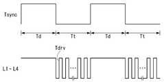
도 4에 도시된 바와 같이, 셀프 터치 센싱 방식의 터치 스크린을 갖는 표시장치는 액정표시패널(DIS)에 영상을 표시하는 디스플레이 구동기간(Td)과 터치 스크린(TSP)을 센싱하는 터치 스크린 구동기간(Tt)이 시간상으로 분할된다. 즉, 디스플레이 구동기간(Td)과 터치 스크린 구동기간(Tt)은 시분할 구동된다.4, the display device having a touch screen of the self-touch sensing type includes a display driving period Td for displaying an image on the liquid crystal display panel DIS and a touch screen driving period for sensing the touch screen TSP (Tt) is divided in time. That is, the display driving period Td and the touch screen driving period Tt are time-division driven.
센싱라인(L1 ~ L4)에는 디스플레이 구동기간(Td) 동안 공통전압(Vcom)이 공급되는 반면, 터치 스크린(TSP) 동안 터치구동신호(Tdrv)가 공급된다. 터치구동신호(Tdrv)는 교류 신호 형태로 생성된다. 디스플레이 구동기간(Td)과 터치 스크린 구동기간(Tt)을 시분할 하기 위한 동기신호(Tsync)는 타이밍 콘트롤러나 호스트 시스템 등으로부터 생성될 수 있다.The common voltage Vcom is supplied to the sensing lines L1 to L4 during the display driving period Td while the touch driving signal Tdrv is supplied during the touch screen TSP. The touch driving signal Tdrv is generated in the form of an AC signal. The synchronizing signal Tsync for time-dividing the display driving period Td and the touch screen driving period Tt may be generated from a timing controller, a host system, or the like.
한편, 위의 설명에서는 터치 스크린 구동회로(30)가 셀프 터치 센싱 방식으로 터치 스크린(TSP)의 터치 유무 및 위치를 센싱하는 것을 일례로 설명하였다. 그러나, 터치 스크린 구동회로(30)는 뮤추얼 터치 센싱 방식으로 터치 스크린(TSP)의 터치 유무 및 위치를 센싱할 수도 있다. 이 경우, 액정표시패널(DIS) 상에는 터치구동신호를 전달하는 Tx라인들과 터치에 의해 가변된 정전용량값을 수신하는 Rx라인들이 형성된다.In the above description, the touch
도 5는 표시장치의 저소비전력 구동 방식을 설명하기 위한 도면이고, 도 6은 종래에 제안된 센싱 방식을 개략적으로 설명하기 위한 도면이다.FIG. 5 is a view for explaining a low power consumption driving method of the display apparatus, and FIG. 6 is a view for schematically explaining a sensing method proposed in the past.
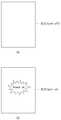
도 5의 (a)에 도시된 바와 같이, 앞서 설명된 표시장치는 사용자가 장치를 사용하지 않을 때 슬립 모드(또는 휴지 모드)로 돌입한다. 반면, 도 5의 (b)에 도시된 바와 같이, 사용자가 액정표시패널(DIS)의 화면을 노크하듯이 X(X는 2 이상 정수)번 터치하면 표시장치는 슬립 모드에서 깨어난다.As shown in Fig. 5 (a), the above-described display device enters a sleep mode (or a sleep mode) when the user is not using the apparatus. On the other hand, as shown in FIG. 5B, when the user touches X (X is an integer equal to or more than two) times as if the user knocks the screen of the liquid crystal display panel DIS, the display device wakes up from the sleep mode.
이하, 도 5의 기능을 노크온(Knock on)이라 명명한다. 도 5에 도시된 바와 같이, 노크온은 표시장치를 사용하지 않을 때, 액정표시패널 등을 휴지시키는 방식으로 장치의 소비전력을 낮출 수 있다. 하지만, 현재까지 제안된 슬립 모드는 소비전력을 저감하기 위한 연구를 지속해야 할 필요성이 있다.Hereinafter, the function of Fig. 5 will be referred to as " knock on ". As shown in Fig. 5, when the display device is not used, the knock-on can reduce the power consumption of the device in such a manner that the liquid crystal display panel is stopped. However, there is a need to continue research to reduce power consumption in the proposed sleep mode.
[종래에 제안된 센싱 방식에 대한 고찰][Consideration on Sensing Methods Proposed in the Conventional Background]
도 6에 도시된 바와 같이, 통상의 셀프 터치 센싱 방식은 인접하는 게이트라인(G1)과 데이터라인(D1)으로 인하여 터치 센서의 커패시터(Cs)의 크기가 커플링(Coupling) 형태로 나타나게 된다.As shown in FIG. 6, in the conventional self-touch sensing method, the size of the capacitor Cs of the touch sensor appears as a coupling type due to the adjacent gate line G1 and the data line D1.
이를 개선하기 위해, 종래에는 센싱라인에 공급되는 터치구동신호의 변조(Modulation)전압과 동일한 전압을 형성하여 게이트라인(G1)과 데이터라인(D1)에 공급하는 방식으로 터치 센서의 커패시터(Cs)를 현저히 줄일 수 있었다.In order to improve this, conventionally, a voltage equal to the modulation voltage of the touch driving signal supplied to the sensing line is formed and supplied to the gate line G1 and the data line D1, Can be significantly reduced.
셀프 터치 센싱 방식을 종래 방식과 같이 구동하면 터치 센서의 커패시터가 줄어들게 되고, 핑거 커패시터(Finger Cap)의 영향이 증가하면서 감도가 향상되고 또한 노이즈에 둔감하게 된다. 이로 인하여, 터치 스크린 구동회로의 구동 능력(Driving Capability)에 제약 사항이 완화되므로 회로의 물리적인 크기도 감소시킬 수 있게 된다.When the self-touch sensing method is operated as in the conventional method, the capacitors of the touch sensor are reduced, and the influence of the finger capacitors is increased, thereby improving the sensitivity and insensitivity to noise. Accordingly, the constraint on the driving capability of the touch screen driving circuit is relaxed, so that the physical size of the circuit can be reduced.
하지만, 종래 방식을 노크온 기능에 적용하기 위해서는 터치구동신호의 변조 전압을 생성하고 버퍼링하는 아날로그 회로가 더 필요하다. 아날로그 회로가 더 부가된 경우, 소비전류 증가의 요인이 되고 게이트라인과 데이터라인의 로드(Load)에 따라 전류가 증가할 수 있게 된다.However, in order to apply the conventional method to the knock-on function, an analog circuit for generating and buffering the modulation voltage of the touch driving signal is further needed. When an analog circuit is further added, the current consumption is increased and the current can be increased according to the load of the gate line and the data line.
이러한 이유로 노크온 기능을 위한 슬립 모드 동작에서는 종래 방식을 사용하는 것만으로 전류 스펙(Spec)을 만족시키기 어려우며 많은 리소스(Resource)를 추가로 사용해야 하는 단점이 발생한다.For this reason, in the sleep mode operation for the knock-on function, it is difficult to satisfy the current specification only by using the conventional system, and a disadvantage that a large amount of resources are used additionally occurs.
그러나, 종래에 제안된 방식을 사용하지 않는 경우 터치 센서의 커패시터가 증가하게 된다. 때문에, 정상 동작을 위해 변조 전압을 줄이거나, 적분 횟수를 제한하거나 터치 스크린 구동회로의 피드백 커패시터(Cfb)를 증가시키는 등 출력 범위 제한(Range Limit)을 피하기 위한 방법을 택해야 한다.However, when the conventional method is not used, the capacitors of the touch sensor are increased. Therefore, for normal operation, a method should be adopted to avoid the range limit, such as reducing the modulation voltage, limiting the number of integrations, or increasing the feedback capacitor (Cfb) of the touch screen driver circuit.
다만, 위의 예를 이용할 경우, 신호대잡음비(SNR)를 감소시키는 방향이므로 문제가 있다. 또한 위의 예를 이용할 경우, 매우 큰 (~수 백 pF) 터치 센서의 커패시터에 따른 포화 문제를 해결하려면 터치 스크린 구동회로의 내부 커패시터를 비슷한 범위로 증가시켜야 하는데 이는 실현 가능성 문제가 제기될 수 있다.However, when the above example is used, there is a problem because it is a direction to reduce a signal-to-noise ratio (SNR). Also, using the above example, to solve the saturation problem due to the capacitors of very large (~ several hundred pF) touch sensors, the internal capacitors of the touch screen driver circuit must be increased to a similar range, which can be a feasibility issue .
[실시예에 따른 센싱 방식의 개념][Concept of sensing method according to the embodiment]
도 7은 본 발명의 제1실시예에 따른 센싱 방식을 개략적으로 설명하기 위한 도면이고, 도 8은 본 발명의 제1실시예에 따른 표시장치의 구동방법을 설명하기 위한 흐름도이다.FIG. 7 is a view for schematically explaining a sensing method according to the first embodiment of the present invention, and FIG. 8 is a flowchart for explaining a method of driving a display device according to the first embodiment of the present invention.
도 7에 도시된 바와 같이, 본 발명의 제1실시예는 노크온 기능을 위한 슬립 모드 동작을 위해 터치 센서들의 전극 구성이 변경된다. 구체적으로, 슬립 모드 동작에서 터치 센서들 간의 뮤추얼 커패시터(Cm)를 센싱하기 위해 블록(또는 포인트) 형태로 나누어진 공통전극들이 라인별로 연결된다. 즉, 노크온 기능에 돌입하면 공통전극들이 블록 형태에서 바 형태(Bar type)(또는 스트라이프 형태)의 터치 센서라인으로 변경된다.As shown in FIG. 7, the first embodiment of the present invention changes the electrode configuration of the touch sensors for the sleep mode operation for the knock-on function. Specifically, the common electrodes divided into blocks (or points) are connected line by line to sense the mutual capacitors Cm between the touch sensors in the sleep mode operation. That is, when entering the knock-on function, the common electrodes are changed from a block type to a bar type (or stripe type) touch sensor line.
예컨대, "Cm1"은 제1라인(Tx)과 제2라인(Rx) 사이의 뮤추얼 커패시터를 의미하고, "Cm2"는 제3라인(Tx)과 제2라인(Rx) 사이의 뮤추얼 커패시터를 의미하며, "Rx(n)"은 제1라인과 제2라인 사이에 형성된 라인을 의미하고, "CPRX"는 제2라인(RX라인)과 그라운드 사이의 기생용량값을 의미한다.For example, "Cm1" means a mutual capacitor between the first line Tx and the second line Rx, and "Cm2" means a mutual capacitor between the third line Tx and the second line Rx Quot; RX (n) " means a line formed between the first line and the second line, and "CPRX " means a parasitic capacitance value between the second line (RX line) and the ground.
위와 같이 구성된 Tx 채널에 구동전압을 인가하면 채널로부터 전달되는 전하량은 뮤추얼 커패시터(Cm)의 변화량과 Tx 구동전압에 의해 결정된다. 이때, Tx 채널에 인가되는 구동전압은 예컨대, 제1구동전압(VEX)과 제2구동전압(VEXB)과 같이 상호 반전된 형태의 보상여기펄스(Complementary Excitation Pulse) 형태로 생성될 수 있으나 이에 한정되지 않는다. 보상여기펄스는 노이즈 등과 같은 신호의 왜곡으로부터 강한 저항력을 갖는다.When a drive voltage is applied to the Tx channel configured as above, the amount of charge transferred from the channel is determined by the amount of change of the mutual capacitor Cm and the Tx drive voltage. At this time, the driving voltage applied to the Tx channel may be generated in the form of a complementary excitation pulse of mutually inverted form such as a first driving voltage VEX and a second driving voltage VEXB, It does not. The compensated excitation pulse has a strong resistance to distortion of the signal such as noise.
터치 스크린 구동회로(센싱회로; ROIC)는 "Vin"으로부터 터치 센서들 간의 뮤추얼 커패시터(Cm) 센싱할 수 있는데, 이를 수식으로 표현하면 다음과 같다.A touch screen driver circuit (sensing circuit; ROIC) can sense a mutual capacitor (Cm) between touch sensors from "Vin "

위의 수식에서, ΔCm은 Cm1과 Cm2 간의 차이값을 의미하고, Cm1은 제1라인의 터치 센서라인에 형성된 커패시터값을 의미하고, Cm2는 제2라인의 터치 센서라인에 형성된 캐패시터값을 의미하고, CPRX는 제2라인(Rx라인)과 그라운드 사이의 기생용량값을 의미하고, VE는 구동전압을 의미한다.In the above equation,? Cm denotes a difference value between Cm1 and Cm2, Cm1 denotes a capacitor value formed in the touch sensor line of the first line, Cm2 denotes a capacitor value formed in the touch sensor line of the second line , CPRX denotes the parasitic capacitance value between the second line (Rx line) and the ground, and VE denotes the driving voltage.
본 발명의 제1실시예에 따르면, 터치 스크린 구동회로(센싱회로; ROIC))의 입력단(반전단자인 "-")으로 전달되는 전하는 커패시터의 분할(Capacitor Dividing)에 의해 결정된다. 그리고 뮤추얼 커패시터(Cm)의 변화량만큼 터치(Touch) 값으로 나타난다.According to the first embodiment of the present invention, the charge transferred to the input terminal ("-") of the touch screen drive circuit (sensing circuit; ROIC)) is determined by the capacitor dividing of the capacitor. And the amount of change of the mutual capacitor Cm is displayed as a touch value.
이로 인하여, 센싱 회로의 구성 시 터치 스크린 내부의 뮤추얼 커패시터와 기생용량값(Rx parasitic 전극의 Cap)의 분할(Dividing)에 의해 출력이 결정되며, 센싱 회로의 내부에는 피드백 커패시터(Feedback Cap)만 존재하도록 설계될 수 있다.Therefore, when the sensing circuit is constructed, the output is determined by dividing the mutual capacitors and the parasitic capacitances (Caps of the Rx parasitic electrodes) in the touch screen, and only the feedback capacitors are present in the sensing circuit .
이로 인하여, 본 발명의 제1실시예는 종래에 제안된 방법에서 나타나는 셀프 터치 센싱시의 포화 문제는 고려하지 않아도 된다. 또한, 필요에 따라 작은 뮤추얼 커패시터(Cm)의 변화량을 증가시키기 위해 적분기의 이득(Gain) 및 적분 횟수의 증가를 통해 검출 가능한 전압(터치 임계점; Touch Threshold) 이상으로 증폭시킬 수 있다.Therefore, the first embodiment of the present invention does not need to consider the saturation problem in the self-touch sensing, which occurs in the conventional method. In addition, the gain can be amplified to a detectable voltage (touch threshold) or higher by increasing the gain of the integrator and the number of integrations in order to increase the variation of the small mutual capacitor Cm as needed.
그러므로, 본 발명의 제1실시예는 장치가 노크온 기능을 위한 슬립 모드 동작에 돌입할 경우, 셀프 터치 센싱 방식에서 뮤추얼 터치 센싱 방식으로 전환된다. 본 발명의 제1실시예는 터치 센서를 갖는 표시장치가 노크온 기능을 수행하는 동안 구동의 안정성 및 신뢰성을 유지하면서 소비전력을 낮출 수 있을 것이다.Therefore, the first embodiment of the present invention switches from the self-touch sensing method to the mutual touch sensing method when the apparatus enters the sleep mode operation for the knock-on function. The first embodiment of the present invention can reduce the power consumption while maintaining stability and reliability of driving while the display device having the touch sensor performs the knock-on function.
그 이유를 설명하면, 뮤추얼 터치 센싱 방식은 뮤추얼 커패시터(Cm)의 변화량만 증폭하므로 출력의 포화(Saturation) 문제없이 원하는 레벨만큼 검출(Detection)할 수 있기 때문이다. 즉, 뮤추얼 터치 센싱 방식은 셀프 터치 센싱 방식 대비 터치 센서의 커패시터가 증가해도 출력 범위를 한정하는 문제(달리 설명하면, 출력의 포화)가 유발되지 않기 때문이다.The reason for this is that the mutual touch sensing method amplifies only the amount of change of the mutual capacitor Cm, so that it can detect a desired level without a problem of output saturation. That is, the mutual touch sensing method does not cause the limitation of the output range (in other words, saturation of the output) even when the capacitors of the touch sensor increase as compared with the self-touch sensing method.
도 8에 도시된 바와 같이, 본 발명의 제1실시예에 따른 표시장치의 구동방법은 노크온 기능을 수행하는 동안 구동의 안정성 및 신뢰성을 유지하면서 소비전력을 낮추는 것이다.As shown in FIG. 8, the driving method of the display device according to the first embodiment of the present invention lowers power consumption while maintaining the stability and reliability of driving while performing the knock-on function.
본 발명의 제1실시예에 따르면, 일반적인 구동 상태에서는 영상을 표시 및 터치 구동을 한다(S110). 영상표시 및 터치 구동기간 동안(노말 모드 또는 비 슬립 모드)에는 제1터치 센싱 방식으로 터치 스크린을 센싱한다. 일반적인 구동 상태에서는 지속적(또는 주기적)으로 입력의 유무를 판별한다(S120).According to the first embodiment of the present invention, in a normal driving state, an image is displayed and a touch driving is performed (S110). During the video display and the touch driving period (normal mode or non-sleep mode), the touch screen is sensed by the first touch sensing method. In the normal driving state, the presence or absence of the input is determined continuously (or periodically) (S120).
입력이 존재하면(Y), 이전과 동일하게 영상표시 및 터치 구동을 하고 또한 제1터치 센싱 방식으로 터치 스크린을 센싱한다(S110). 이와 달리, 입력이 존재하지 않으면(N), 표시장치는 슬립 모드로 돌입한다(S130).If there is an input (Y), image display and touch driving are performed in the same manner as before, and the touch screen is sensed by the first touch sensing method (S110). Otherwise, if there is no input (N), the display device enters the sleep mode (S130).
표시장치가 슬립 모드에 돌입하면, 이전과 달리 영상을 비표시 및 터치 구동을 한다(S140). 영상비표시 및 터치 구동기간 동안(슬립 모드)에는 제2터치 센싱 방식으로 터치 스크린을 센싱한다. 슬립 모드에서는 지속적(또는 주기적)으로 노크온의 유무를 판별한다(S150).When the display apparatus goes into the sleep mode, the image is not displayed and the touch operation is performed unlike the previous case (S140). During the video image display and the touch driving period (sleep mode), the touch screen is sensed by the second touch sensing method. In the sleep mode, the presence or absence of knock-on is determined continuously (or periodically) (S150).
노크온이 미발생하면(N), 이전과 동일하게 영상비표시 및 터치 구동을 하고 또한 제2터치 센싱 방식으로 터치 스크린을 센싱한다(S140). 이와 달리, 노크온이 발생하면(Y), 표시장치는 슬립 모드가 해제된다(S160). 즉, 노크온의 유무에 따라 센싱 모드는 전환된다.If no knock-on occurs (N), image display and touch driving are performed in the same manner as before, and the touch screen is sensed by the second touch sensing method (S140). On the other hand, when knock-on occurs (Y), the display device is released from the sleep mode (S160). That is, the sensing mode is switched depending on the presence or absence of knock-on.
표시장치가 슬립 모드에서 해제되면, 이전과 달리 영상을 표시 및 터치 구동을 한다(S170). 영상표시 및 터치 구동기간 동안(노말 모드 또는 비 슬립 모드)에는 제1터치 센싱 방식으로 터치 스크린을 센싱한다.When the display device is released from the sleep mode, the image is displayed and touched (S170). During the video display and the touch driving period (normal mode or non-sleep mode), the touch screen is sensed by the first touch sensing method.
본 발명의 제1실시예에 따른 표시장치의 구동방법은 표시장치가 일반적인 구동 상태(노말 모드 또는 비 슬립 모드)로 동작하는 경우, 제1터치 센싱 방식으로 터치 스크린을 센싱한다. 이때, 제1터치 센싱 방식은 셀프 터치 센싱 방식으로 선택된다.The method of driving a display device according to the first embodiment of the present invention senses a touch screen by a first touch sensing method when the display device operates in a general driving state (normal mode or non-sleep mode). At this time, the first touch sensing method is selected as a self-touch sensing method.
이와 달리, 표시장치가 슬립 모드로 동작하는 경우, 제1터치 센싱 방식과 다른 제2터치 센싱 방식으로 터치 스크린을 센싱한다. 이때, 제2터치 센싱 방식은 뮤추얼 터치 센싱 방식으로 선택된다.Alternatively, when the display device operates in the sleep mode, the touch screen is sensed by a second touch sensing method different from the first touch sensing method. At this time, the second touch sensing method is selected by the mutual touch sensing method.
도 7을 참조하여 기 설명한 바와 같이, 뮤추얼 터치 센싱 방식은 노크온 기능을 수행하는 동안 셀프 터치 센싱 방식 대비 구동의 안정성 및 신뢰성을 유지하면서 소비전력을 낮출 수 있다. 그러므로, 도 8과 같이 구동 모드의 전환에 맞추어 센싱 방식을 변경하는 것만으로도 위와 같이 괄목할 만한 효과를 나타낼 수 있는 것으로 검토된다.As described above with reference to FIG. 7, the mutual touch sensing method can reduce the power consumption while maintaining stability and reliability of driving compared to the self-touch sensing method while performing the knock-on function. Therefore, it is considered that such a remarkable effect can be obtained by merely changing the sensing method in accordance with the switching of the drive mode as shown in Fig.
이하, 본 발명에 대한 이해를 돕기 위한 예를 구체화한다. 다만, 이하의 설명에서는 표시장치가 슬립 모드로 동작하게 됨에 따른 터치 센서들의 전극 구성의 변화와 센싱 방식의 변화를 중점으로 설명한다. 아울러, 표시장치가 슬립 모드로 동작하기 전에는 터면Hereinafter, an example for facilitating understanding of the present invention will be described. In the following description, the change of the electrode configuration of the touch sensors and the change of the sensing method as the display device operates in the sleep mode will be described. Further, before the display device operates in the sleep mode,
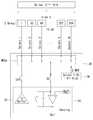
도 9는 본 발명의 제1실시예를 구체화한 장치의 구성 예시도이고, 도 10은 노크온 모드에서 외곽 라인의 동작 특성을 보여주는 예시도이며, 도 11은 도 9에 도시된 제1라인의 구동 예시도이며, 도 12는 도 9에 도시된 제2라인의 구동 예시도이고, 도 13은 도 9에 도시된 제3라인의 구동 예시도이다.FIG. 9 is a diagram showing an example of the configuration of an apparatus embodying the first embodiment of the present invention, FIG. 10 is an exemplary view showing operation characteristics of an outline in a knock-on mode, FIG. 12 is a driving example of the second line shown in FIG. 9, and FIG. 13 is a driving example of the third line shown in FIG.
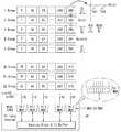
도 9에 도시된 바와 같이, 본 발명의 제1실시예는 표시장치가 슬립 모드로 동작하게 되면 블록(또는 포인트) 형태로 구성된 터치 센서의 전극이 바 형태로 변경된다.As shown in FIG. 9, in the first embodiment of the present invention, when the display device operates in the sleep mode, the electrodes of the touch sensor configured in a block (or point) form are changed into bars.
예컨대, 첫 번째 라인에서 블록 형태로 구성된 터치 센서의 전극(0, 32, 64 ... 256, 288)은 제1먹스신호(1MUX)에 의해 모두 쇼트되어 바 형태로 변경된다. 그리고 두 번째 라인에서 블록 형태로 구성된 터치 센서의 전극(1 33, 65 ... 257, 289)은 제2먹스신호(2MUX)에 의해 모두 쇼트되어 바 형태로 변경된다.For example, the electrodes (0, 32, 64, 256, and 288) of the touch sensor configured in the form of a block in the first line are all shorted by the first mux signal 1MUX and changed to a bar shape. In the second line, the electrodes (1 33, 65 ... 257, and 289) of the touch sensor configured in a block form are all shorted by the second mux signal (2 MUX) and changed into a bar shape.
이와 같은 형태로, 세 번째 라인부터 서른두 번째 라인까지 각 라인에 위치하는 제3먹스신호(3MUX) 내지 제32먹스신호(32MUX)에 의해 모두 쇼트되어 바 형태로 변경된다.In this manner, all of the third to Mux signals 32MUX to 32MUX located in the respective lines from the third line to the thirty-second line are short-circuited and changed to a bar form.
블록 형태로 구성된 터치 센서의 전극들이 제1먹스신호(1MUX) 내지 제32먹스신호(32MUX)에 의해 라인별로 쇼트되어 바 형태로 변경된다는 것은 미도시되어 있지만, 가로 방향의 각 블록을 전기적으로 연결하는 스위치 또는 이와 대응되는 기능을 수행할 수 있는 장치가 형성되어 있음을 의미한다.Although it is not shown that the electrodes of the touch sensor constructed in a block form are short-circuited by the first to third multiplex signals 32MUX to 32MUX to change into a bar shape, it is also possible to electrically connect the blocks in the horizontal direction Or a device capable of performing a corresponding function is formed.
이하에서는 첫 번째 라인의 터치 센서의 전극(0, 32, 64 ... 256, 288) 내지 서른두 번째 라인의 터치 센서의 전극(31, 63, 95 ... 587, 319)을 제1그룹 터치 센서(1Group)로 명명한다.Hereinafter, the electrodes (31, 63, 95 ... 587, 319) of the touch sensor of the first line touch sensor (0, 32, 64 ... 256, 288) It is called touch sensor (1 group).
제1그룹 터치 센서(1Group) 내지 제32그룹 터치 센서(32Group)는 먹스(MUXs)에 각각 한 라인씩 연결된다. 먹스(MUXs)는 10:1과 같이 1개의 입출력 채널과 10개의 입출력 채널로 구성된 것을 일례로 하였으나 이에 한정되지 않는다.The first group touch sensor 1Group to the 32nd group touch sensor 32Group are connected to the MUXs one by one. The MUXs are configured as one input / output channel and 10 input / output channels as in the case of 10: 1, but the present invention is not limited thereto.
먹스(MUXs)는 터치 스크린 구동회로(30)의 내부에 포함된다. 먹스(MUXs)는 터치 스크린 구동회로(30)의 내부에 포함된 센싱회로 및 구동회로(Sensing Block & Tx Buffer)에 연결된다.The MUXs are included in the touch-
먹스(MUXs)는 시분할 방식으로 구동되며 센싱회로 및 구동회로(Sensing Block & Tx Buffer)와 전기적으로 연결되는 채널을 선택적으로 제어하는 역할을 한다. 먹스(MUXs)는 제1먹스신호(1MUX) 내지 제32먹스신호(32MUX)에 대응하여 제1그룹 터치 센서(1Group) 내지 제32그룹 터치 센서(32Group) 중 적어도 한 라인을 쇼트시킨다.MUXs are driven in a time-division manner and selectively control the channels electrically connected to the sensing circuit and the driving circuit (Sensing Block & Tx Buffer). The MUXs short at least one of the first group touch sensor 1Group to the 32nd group touch sensor 32Group corresponding to the first to Mux signal 32MUX to the first to Mux signal 32MUX.
위와 같은 구성에 의해, 표시장치가 슬립 모드로 동작하게 되면 터치 스크린 구동회로(30)는 제1먹스신호(1MUX) 내지 제32먹스신호(32MUX)를 출력하여 가로 방향으로 10개의 블록씩 쇼트시켜 하나의 라인을 터치 센서 그룹으로 구성을 변경한다. 즉, 터치 스크린 구동회로(30)는 터치 스크린의 전극의 구성을 변경한다.When the display apparatus is operated in the sleep mode, the touch
표시장치가 노말 모드(또는 비 슬립 모드)로 동작할 때에는 총 319개의 터치 센서가 블록 형태로 존재하지만, 표시장치가 슬립 모드로 동작할 때에는 총 32개의 터치 센서가 라인 형태로 존재하는 것으로 변경된다. 한편, 위의 설명에서 보이는 터치 센서, 먹스 및 먹스신호의 개수는 설명의 이해를 돕기 위한 예시일 뿐 이에 한정되지 않는다.When the display apparatus operates in the normal mode (or non-sleep mode), a total of 319 touch sensors exist in a block form, but when the display apparatus operates in the sleep mode, a total of 32 touch sensors are changed to exist in a line form . Meanwhile, the numbers of the touch sensor, the mux and the mux signal shown in the above description are only examples for helping understanding of the explanation.
표시장치가 슬립 모드로 동작하게 되면 터치 스크린 구동회로(30)는 터치 스크린의 전극의 구성을 변경함과 더불어, 자신의 채널들을 Tx채널과 Rx채널로 구분 짓는다. 이때, 터치 스크린 구동회로(30)는 자신의 채널들을 i개(i는 2 이상 정수)의 Tx채널과 j개(j는 2 이상 정수)의 Rx채널로 구분할 수 있다.When the display apparatus operates in the sleep mode, the touch
예컨대, 제1그룹 터치 센서(1Group)에 연결된 센싱 라인은 Tx채널로 변경되고, 제2그룹 터치 센서(2Group)에 연결된 센싱 라인은 Rx채널로 변경되고, 제3라인 터치 센서(3Group)에 연결된 센싱 라인은 Tx채널로 변경된다.For example, the sensing line connected to the first group touch sensor 1Group is changed to the Tx channel, the sensing line connected to the second group touch sensor 2Group is changed to the Rx channel, and the sensing line connected to the third line touch sensor 3Group The sensing line is changed to Tx channel.
표시장치가 슬립 모드로 동작하게 되면 터치 스크린 구동회로(30)는 자신의 채널들을 구분함과 더불어, 자신의 Tx채널들을 통해 제1구동전압(VEX)과 제2구동전압(VEXB)을 출력한다. 이때, 제1구동전압(VEX)과 제2구동전압(VEXB)은 기 설명한 바와 같이 상호 반전된 형태의 보상여기펄스(Complementary Excitation Pulse) 형태로 생성될 수 있으나 이에 한정되지 않는다.When the display device operates in the sleep mode, the touch
한편, 제1그룹 터치 센서(1Group)과 제3그룹 터치 센서(3Group)를 동일한 형태(또는 동일한 위상)의 펄스로 동작시키면, 제2그룹 터치 센서(2Group)에는 커플링 용량(coupling cap)이 형성된다. 이 경우, Rx채널의 전위는 Tx채널처럼 끌려 올라가게 된다. 그러므로, Rx채널의 출력값이 포화(saturation)되지 않도록 Rx채널의 양단에 위치하는 Tx채널의 위상은 반전된 형태가 바람직하다.When the first group touch sensor 1Group and the third group touch sensor 3Group are operated with pulses having the same shape (or the same phase), the coupling capacities of the second group touch sensors 2Group are . In this case, the potential of the Rx channel is pulled up like a Tx channel. Therefore, the phase of the Tx channel located at both ends of the Rx channel is preferably inverted so that the output value of the Rx channel is not saturated.
표시장치가 슬립 모드로 동작하게 되면 터치 스크린 구동회로(30)는 자신의 Tx채널들을 통해 구동전압을 출력한 다음 Rx채널들을 통해 뮤추얼 커패시터(Cm1, Cm2)의 변화량을 수신하고 노크온의 유무를 판별한다.When the display device operates in the sleep mode, the touch
노크온이 미발생하면, 표시장치는 이전과 동일하게 영상비표시 및 터치 구동(뮤추얼 터치 센싱)을 하게 된다. 노크온이 발생하면, 표시장치는 슬립 모드가 해제되고, 이전과 달리 영상표시 및 터치 구동(셀프 터치 센싱)을 하게 된다.If no knock-on occurs, the display device performs image display and touch driving (mutual touch sensing) in the same manner as before. When knock-on occurs, the display device is released from the sleep mode and performs video display and touch driving (self-touch sensing) unlike the previous case.
한편, 위의 설명에서 터치 스크린 구동회로(30)는 터치 센서 전극의 커패시터의 개수만큼 센싱회로를 내장하기 어렵다. 터치 스크린 구동회로(30)의 입력단에 위치하는 먹스(MUXs)는 채널을 반복적으로 구동하므로 터치 센서 전극의 커패시터의 개수만큼 센싱회로를 내장하기 어려운 문제를 해소하여 센싱회로의 개수 감소 효과를 갖는다.In the above description, it is difficult for the touch
아울러, 프레임 레이트(Frame rate)에 문제가 없다면 먹스 채널의 개수 증가를 통해 센싱회로의 개수를 줄여 터치 스크린 구동회로(30)의 소비전력을 줄일 수도 있다. 한편, 위의 설명에서는 1개의 먹스당 N개의 채널을 먹스신호로 제어하여 연결하게 된다.In addition, if there is no problem with the frame rate, the number of sensing circuits can be reduced by increasing the number of mux channels, thereby reducing the power consumption of the touch
그런데, 터치 스크린 구동회로(30)가 터치 센서의 전극의 커패시터를 구동할 수 있는 능력에 따라 쇼트되는 라인의 개수를 늘리(구동 능력이 우수할 때)거나 줄이(구동 능력이 부족할 때)는 형태로 쇼트되는 라인을 조절할 수도 있다.However, if the number of lines to be short-circuited (when the driving ability is excellent) or the number of lines to be short-circuited (when the driving ability is insufficient) depends on the ability of the touch
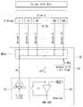
도 10에 도시된 바와 같이, 표시장치가 슬립 모드로 동작할 경우, 터치 스크린 구동회로(30)는 제1그룹 터치 센서(1Group) 내지 제32그룹 터치 센서(32Group)에서 내곽에 존재하는 터치 전극(U_Area)만 사용하고 외곽(또는 최외곽)에 존재하는 터치 전극(NU_Area)은 사용하지 않을 수 있다.10, when the display device operates in the sleep mode, the touch
노크온 기능 사용시 사용자가 외곽(또는 최외곽)에 존재하는 터치 전극을 터치하지 않는 것으로 간주하고 외곽값을 사용하지 않으면 그 만큼 소비전력을 절감할 수 있기 때문이다. 노크온 기능 사용시 터치 스크린 구동회로(30)는 외곽(또는 최외곽)에 존재하는 터치 전극(NU_Area)을 사용하지 않기 위해, 이 영역에 포함된 Tx채널, Rx채널 또는 Tx 및 Rx채널을 동작시키지 않을 수 있다.This is because, when the knock-on function is used, the user considers that the touch electrode existing in the outer edge (or the outermost edge) is not touched and the power consumption can be reduced by not using the outer edge value. When the knock-on function is used, the touch
한편, 액정표시패널과 터치 스크린 구동회로(30) 간에는 특성 편차가 존재할 수 있다. 액정표시패널과 터치 스크린 구동회로(30) 간에 특성 편차가 존재할 경우 Rx채널 간에 편차가 발생한다. 따라서, 터치의 유무를 판별하는 터치 임계점(값)은 액정표시패널의 특성에 맞는 사전 실험값으로 설정되어야 한다.On the other hand, there may be a characteristic deviation between the liquid crystal display panel and the touch
표시장치가 슬립 모드로 동작할 경우, 터치 스크린 구동회로(30)는 내부 알고리즘을 사용하지 못하므로 Rx채널로부터 출력되는 절대값만으로 터치의 유무를 판단할 수 있다. 이후, 터치로 판단되면 타이밍 콘트롤러는 터치 스크린 구동회로(30)를 슬립 모드에서 깨우기 위한 신호를 출력한다.When the display apparatus operates in the sleep mode, the touch
한편, 도 9에서는 터치 센서들이 가로 방향으로 그룹 터치 센서가 구성되는 것을 일례로 하였다. 그러나 이는 하나의 예시일 뿐, 터치 센서들은 표시장치의 모델에 따라 가로 방향 또는 세로 방향으로 그룹 터치 센서가 구성될 수 있다.9 shows an example in which the group of touch sensors are configured in the horizontal direction. However, this is only an example, and the touch sensors may be configured as a group touch sensor in the horizontal direction or the vertical direction depending on the model of the display device.
본 발명의 제1실시예에 따르면 터치 스크린 구동회로(30)는 표시장치가 슬립 모드로 동작할 경우, 다음과 같이 라인 단위로 뮤추얼 터치 센싱을 진행한다. 이하, 표시장치는 슬립 모드 상태인 것을 예로 설명한다.According to the first embodiment of the present invention, when the display device operates in the sleep mode, the touch
도 11에 도시된 바와 같이, 터치 스크린 구동회로(30)의 먹스선택부(36)는 터치 스크린의 첫 번째 라인(Line 1)에 위치하는 블록 형태의 터치 센서들을 선택하기 위해 10개의 전극을 쇼트(Select 1 ~ 10 = All High)시키는 제1먹스신호(1MUX)를 출력한다. 이로 인하여, 첫 번째 라인(Line 1)에 위치하는 블록 형태의 터치 센서들(0, 32, 64 ... 256, 288)은 하나의 제1그룹 터치 센서(1Group)로 변경된다.11, the
터치 스크린 구동회로(30)의 구동회로(32)는 제1그룹 터치 센서(1Group)를 통해 제1구동전압을 출력한다. 즉, 제1그룹 터치 센서(1Group)는 Tx채널에 연결된 상태이다. 터치 스크린 구동회로(30)의 구동회로(32)가 제1구동전압을 출력하는 동안 터치 스크린 구동회로(30)의 센싱회로(34)는 턴오프된 상태를 취할 수 있다.The driving
도 12에 도시된 바와 같이, 터치 스크린 구동회로(30)의 먹스선택부(36)는 터치 스크린의 두 번째 라인(Line 2)에 위치하는 블록 형태의 터치 센서들을 선택하기 위해 10개의 전극을 쇼트(Select 1 ~ 10 = All High)시키는 제2먹스신호(2MUX)를 출력한다. 이로 인하여, 두 번째 라인(Line 2)에 위치하는 블록 형태의 터치 센서들(1, 33, 65 ... 257, 289)은 하나의 제2그룹 터치 센서(2Group)로 변경된다.12, the
터치 스크린 구동회로(30)의 센싱회로(34)는 제2그룹 터치 센서(2Group)를 통해 뮤추얼 커패시터의 변화량을 센싱한다. 즉, 제2그룹 터치 센서(2Group)는 Rx채널에 연결된 상태이다. 터치 스크린 구동회로(30)의 센싱회로(32)가 뮤추얼 커패시터의 변화량을 센싱하는 동안 터치 스크린 구동회로(30)의 구동회로(34)는 턴오프된 상태를 취할 수 있다.The
도 13에 도시된 바와 같이, 터치 스크린 구동회로(30)의 먹스선택부(36)는 터치 스크린의 세 번째 라인(Line 3)에 위치하는 블록 형태의 터치 센서들을 선택하기 위해 10개의 전극을 쇼트(Select 1 ~ 10 = All High)시키는 제3먹스신호(3MUX)를 출력한다. 이로 인하여, 세 번째 라인(Line 3)에 위치하는 블록 형태의 터치 센서들(2, 34, 66 ... 258, 290)은 하나의 제3그룹 터치 센서(3Group)로 변경된다.13, the
터치 스크린 구동회로(30)의 구동회로(32)는 제3그룹 터치 센서(3Group)를 통해 제2구동전압을 출력한다. 즉, 제3그룹 터치 센서(3Group)는 Tx채널에 연결된 상태이다. 터치 스크린 구동회로(30)의 구동회로(32)가 제2구동전압을 출력하는 동안 터치 스크린 구동회로(30)의 센싱회로(34)는 턴오프된 상태를 취할 수 있다.The driving
터치 스크린 구동회로(30)는 위와 같은 진행 방식으로 한 라인의 그룹에 구동전압을 출력하고 다음 라인의 그룹을 통해 뮤추얼 커패시터의 변화량을 센싱하며, 터치 스크린을 라인 단위로 센싱하며 노크온의 유무를 판별할 수 있다.The touch
표시장치가 슬립 모드로 동작하게 되면 터치 스크린 구동회로(30)는 터치에 따른 좌표를 검출하기보다는 터치의 유무만 판별하면 된다. 그러므로, 본 발명의 제1실시예와 같이 슬립 모드 상태에서 노크온의 유무만 판별할 수 있는 센싱 방식을 취하면 소비전력을 저감할 수 있게 된다.When the display apparatus is operated in the sleep mode, the touch
한편, 본 발명의 제1실시예와 같이 표시장치를 구현하면, 터치 스크린 구동회로(30) 내에 구동전압(Tx Excitation)을 생성하기 위한 인버터 버퍼(32; Inverter Buffer)만 더 구성하더라도 별도의 회로 추가 없이 뮤추얼 커패시터의 변화량을 검출할 수 있다.If the display device is implemented as in the first embodiment of the present invention, even if only the inverter buffer (32) for generating the driving voltage (Tx excitation) is further included in the touch
아울러, 본 발명의 제1실시예와 같이 표시장치를 구현하면, 종래 기술을 사용하지 않고도 소비전류를 감소시킬 수 있다. 그리고 터치 스크린 구동회로(30) 내에 존재하던 먹스를 그대로 이용 가능하다. 그리고 먹스로 터치 센서의 전극을 쇼트 시켰을 때, 센싱 회로가 구동하기 어려울 경우, 적절한 제어를 통해 센싱할 커패시터의 용량(적정 Cap 크기)를 결정하여 쇼트되는 라인들의 수를 결정할 수 있다.In addition, when the display device is implemented as in the first embodiment of the present invention, the consumption current can be reduced without using the conventional technique. The mux existing in the touch
아울러, 본 발명의 제1실시예와 같이 표시장치는 슬립 모드 동작시 셀프 터치 센싱 방식에 비해 동적 범위(Dynamic Range)가 넓고, 커패시터의 크기가 매우 작은 뮤추얼 터치 센싱 방식을 사용한다. 그러므로 구동전압 변조의 증가에 따른 신호대잡음비(SNR) 향상, 피드백 커패시터의 크기(Feedback Cap Size) 감소 및 충전된 전하 제거(Charge Removing)를 위한 회로를 추가하지 않아도 된다.In addition, as in the first embodiment of the present invention, the display device uses a mutual touch sensing method in which a dynamic range is wider and a capacitance of a capacitor is very small as compared with a self-touch sensing method in a sleep mode operation. Therefore, it is not necessary to add a circuit for improving the signal-to-noise ratio (SNR) according to the increase of driving voltage modulation, reducing the feedback capacitor size and charging charge removal.
이하, 본 발명의 제2실시예에 대해 설명한다.Hereinafter, a second embodiment of the present invention will be described.
<제2실시예>≪
도 14는 본 발명의 제2실시예에 따라 블록 단위 센싱을 위한 터치 센서의 구성 예시도이고, 도 15는 도 14의 블록 단위 센싱시 쇼트되는 영역의 예시도이다.FIG. 14 is a diagram illustrating a configuration of a touch sensor for block-based sensing according to a second embodiment of the present invention, and FIG. 15 is a diagram illustrating an example of a region shot in block-based sensing of FIG.
한편, 위의 설명에서는 표시장치가 슬립 모드로 동작할 시 터치 스크린 구동회로(30)가 터치 스크린을 한 라인씩 쇼트한 후 라인 단위로 센싱하며 노크온의 유무를 판별하는 것을 일례로 설명하였다.In the above description, when the display apparatus operates in the sleep mode, the touch
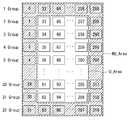
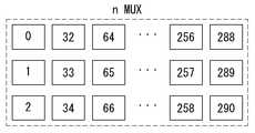
그러나, 도 14에 도시된 바와 같이 표시장치가 특정 모드(예컨대, 슬립 모드, 영상 비표시모드 등)로 동작할 시 터치 스크린 구동회로(30)는 터치 스크린의 가로방향(또는 게이트라인 방향)에 대하여 N(N은 2 이상 정수)개의 라인씩 쇼트(nMUX)시킬 수 있다. 이때, 터치 스크린 구동회로(30)는 블록 단위 센싱을 할 수 있게 된다.However, when the display device operates in a specific mode (for example, a sleep mode, an image non-display mode, or the like) as shown in FIG. 14, the touch
본 발명의 제2실시예는 표시장치가 특정 모드로 동작 시 특정 영역만 블록 단위로 센싱을 하도록 구현된다. 도 15에 도시된 바와 같이, 스마트폰(SMT)의 표시장치가 특정 모드로 동작시 표시면(AA)의 중앙영역(CA)만 블록 단위로 센싱을 할 수 있도록 터치 스크린의 가로방향에 대하여 N(N은 2 이상 정수)개의 라인씩 쇼트(nMUX)시킬 수 있다.The second embodiment of the present invention is implemented such that the display device operates in a specific mode and performs sensing on a block-by-block basis only in a specific area. As shown in FIG. 15, when the display device of the smart phone SMT operates in a specific mode, N (N) is applied to the horizontal direction of the touch screen so that the central area CA of the display surface AA can be sensed in units of blocks. (N is an integer of two or more) can be shorted (nMUX).
그러나, 이는 하나의 예시일 뿐, 블록 단위로 센싱을 할 수 있는 영역은 사용자 등에 의해 변경될 수도 있다. 아울러 본 발명의 제2실시예에 따르면, 특정 모드로 동작 시 라인 단위나 블록 단위뿐만 아니라 터치 스크린의 모든 전극을 쇼트시킨 후 전체센싱을 할 수도 있다.However, this is only an example, and the area that can be sensed on a block-by-block basis may be changed by a user or the like. According to the second embodiment of the present invention, all the electrodes of the touch screen as well as the line unit or the block unit can be short-circuited and then the entire sensing can be performed.
이상, 본 발명의 실시예들에서는 표시장치가 슬립 모드로 동작할 때를 일례로 설명하였다. 그러나, 이는 하나의 예시일 뿐, 본 발명은 표시장치가 특정 모드로 동작할 때 센싱 방식을 전환하는 형태로 적용될 수도 있다. 그리고 이를 위해 터치 스크린의 전극을 선택적으로 쇼트시키는 바 다양한 형태의 센싱이 가능하다.In the embodiments of the present invention, the display device operates in the sleep mode as an example. However, this is only an example, and the present invention may be applied to a mode of switching the sensing method when the display device operates in a specific mode. For this purpose, various types of sensing can be performed by selectively shorting the electrodes of the touch screen.
예컨대, 본 발명은 N개의 먹스를 묶어서 각각의 라인을 Tx채널/Rx채널로 사용하여 뮤추얼 센싱(mutual sensing)이 가능하고 또한 각각의 라인을 셀프 센싱 모드(Self sensing mode)로도 사용 가능하다. 또한, 일정한 블록(예: 정사각형 또는 직사각형 형태)로 묶어서 각각을 Tx채널/Rx채널로 사용하여 뮤추얼 센싱이 가능하고 또한 각각의 블록을 단위 센서(sensor)로 하여 셀프 센싱 모드로 사용 가능하다. 그리고 이를 확장시켜 전체 센서를 하나의 터치 센서(Touch Sensor)로 묶어서 셀프 센싱 방법으로 터치를 판별하는 방법 역시 가능하다.For example, the present invention can use mutual sensing using Tx channel / Rx channel by bundling N muxes, and each line can also be used as a self sensing mode. In addition, it is possible to use mutual sensing by using a Tx channel / Rx channel as a unit block (for example, a square or a rectangular shape), and to use each block as a unit sensor in a self-sensing mode. Also, it is possible to extend the touch sensor by combining all the sensors with a single touch sensor so as to discriminate the touch by a self-sensing method.
이상 본 발명은 터치 센서를 갖는 전자장치가 특정 모드(예컨대, 슬립 모드)를 수행하는 동안 구동의 안정성 및 신뢰성을 유지하면서 소비전력을 낮출 수 있는 효과가 있다. 또한, 본 발명은 터치 센서를 갖는 전자장치를 인셀 터치 방식과 뮤추얼 터치 센싱 방식과 같이 센싱 방식을 전환할 수 있는 효과가 있다. 또한, 본 발명은 저전력 모드 구현하면서 터치 검출을 하기 위한 방법으로 터치 센서의 커패시터의 크기에 따른 포화 문제를 회피할 수 있는 효과가 있다.As described above, the present invention has the effect of reducing the power consumption while maintaining the stability and reliability of the driving while the electronic device having the touch sensor performs a specific mode (e.g., sleep mode). In addition, the present invention has an effect that the electronic device having the touch sensor can switch the sensing method such as the in-cell touch method and the mutual touch sensing method. In addition, the present invention has an effect of avoiding a saturation problem depending on the size of a capacitor of a touch sensor by performing touch detection while implementing a low power mode.
이상 첨부된 도면을 참조하여 본 발명의 실시예를 설명하였지만, 상술한 본 발명의 기술적 구성은 본 발명이 속하는 기술 분야의 당업자가 본 발명의 그 기술적 사상이나 필수적 특징을 변경하지 않고서 다른 구체적인 형태로 실시될 수 있다는 것을 이해할 수 있을 것이다. 그러므로 이상에서 기술한 실시 예들은 모든 면에서 예시적인 것이며 한정적인 것이 아닌 것으로서 이해되어야 한다. 아울러, 본 발명의 범위는 상기 상세한 설명보다는 후술하는 특허청구범위에 의하여 나타내어진다. 또한, 특허청구범위의 의미 및 범위 그리고 그 등가 개념으로부터 도출되는 모든 변경 또는 변형된 형태가 본 발명의 범위에 포함되는 것으로 해석되어야 한다.While the present invention has been described in connection with what is presently considered to be practical exemplary embodiments thereof, it is to be understood that the invention is not limited to the disclosed embodiments, but, on the contrary, It will be understood that the invention may be practiced. It is therefore to be understood that the embodiments described above are to be considered in all respects only as illustrative and not restrictive. In addition, the scope of the present invention is indicated by the following claims rather than the detailed description. Also, all changes or modifications derived from the meaning and scope of the claims and their equivalents should be construed as being included within the scope of the present invention.
20: 타이밍 콘트롤러12: 데이터 구동회로
14: 스캔 구동회로DIS: 액정표시패널
TSP: 터치 스크린30: 터치 스크린 구동회로
MUXs: 먹스36: 먹스선택부20: timing controller 12: data driving circuit
14: scan drive circuit DIS: liquid crystal display panel
TSP: Touch screen 30: Touch screen drive circuit
MUXs: Mux 36: Mux Selection
Claims (9)
Translated fromKorean상기 표시패널에 위치하는 전극으로 구성된 터치 스크린; 및
상기 터치 스크린을 구동하되, 상기 표시패널의 표시 모드에 대응하여 상기 터치 스크린을 제1터치 센싱 방식으로 구동하거나 상기 제1터치 센싱 방식과 다른 제2터치 센싱 방식으로 구동하도록 센싱 모드를 전환하는 터치 스크린 구동회로를 포함하는 터치 센서를 갖는 전자장치.Display panel;
A touch screen including electrodes positioned on the display panel; And
The touch screen is driven by the first touch sensing method corresponding to the display mode of the display panel or the touch mode is switched by the second touch sensing method different from the first touch sensing method, An electronic device having a touch sensor including a screen drive circuit.
상기 터치 스크린 구동회로는
상기 표시패널의 표시 모드에 대응하여 셀프 터치 센싱 방식으로 모드가 전환되거나 뮤추얼 터치 센싱 방식으로 모드가 전환되는 것을 특징으로 하는 터치 센서를 갖는 전자장치.The method according to claim 1,
The touch screen driving circuit
Wherein the mode is switched by the self-touch sensing mode or the mode is switched by the mutual touch sensing mode in accordance with the display mode of the display panel.
상기 터치 스크린 구동회로는
상기 표시패널이 영상을 표시하는 노말 모드 상태일 때 셀프 터치 센싱 방식으로 상기 터치 스크린을 구동하고,
상기 표시패널이 영상을 비표시하는 슬립 모드 상태일 때 뮤추얼 터치 센싱 방식으로 상기 터치 스크린을 구동하는 것을 특징으로 하는 터치 센서를 갖는 전자장치.The method according to claim 1,
The touch screen driving circuit
The touch panel is driven by a self-touch sensing method when the display panel is in a normal mode in which an image is displayed,
Wherein the touch panel is driven by a mutual touch sensing method when the display panel is in a sleep mode in which the display panel does not display an image.
상기 터치 스크린 구동회로가 상기 제2터치 센싱 방식으로 상기 터치 스크린을 구동할 경우,
상기 터치 스크린의 블록(또는 포인트) 형태로 구성된 전극들은 상기 터치 스크린의 제1방향에 대하여 적어도 하나의 라인씩 쇼트되는 것을 특징으로 하는 터치 센서를 갖는 전자장치.The method according to claim 1,
When the touch screen driving circuit drives the touch screen by the second touch sensing method,
Wherein the electrodes configured in the form of a block (or point) of the touch screen are shorted by at least one line in a first direction of the touch screen.
상기 터치 스크린 구동회로가 상기 제2터치 센싱 방식으로 상기 터치 스크린을 구동할 경우,
상기 터치 스크린의 블록(또는 포인트) 형태로 구성된 전극들은 상기 터치 스크린의 제1방향에 대하여 하나의 라인, 제1방향에 대하여 N개의 라인 또는 모두 쇼트되는 것을 특징으로 하는 터치 센서를 갖는 전자장치.The method according to claim 1,
When the touch screen driving circuit drives the touch screen by the second touch sensing method,
Wherein electrodes formed in the form of a block (or point) of the touch screen are shorted to one line with respect to the first direction of the touch screen and to N lines with respect to the first direction.
상기 표시패널에 위치하는 전극으로 구성된 터치 스크린; 및
상기 터치 스크린을 구동하되, 상기 표시패널의 표시 모드가 변경되면,
상기 터치 스크린의 블록(또는 포인트) 형태로 구성된 전극들이 상기 터치 스크린의 제1방향에 대하여 적어도 하나의 라인씩 쇼트되도록 제어하는 것을 특징으로 하는 터치 센서를 갖는 전자장치.Display panel;
A touch screen including electrodes positioned on the display panel; And
Wherein when the display mode of the display panel is changed,
Wherein the control unit controls the electrodes formed in a block (or point) shape of the touch screen to be shorted by at least one line in the first direction of the touch screen.
상기 표시패널에 입력 유무를 판별하고, 입력이 미존재하면 슬립 모드로 돌입하고, 상기 표시패널에 영상을 비표시하고 상기 제1터치 센싱 방식과 다른 제2터치 센싱 방식으로 상기 터치 스크린을 구동하는 단계; 및
상기 표시패널을 터치하는 노크온이 발생하면 상기 슬립 모드를 해제하고 상기 표시패널에 영상을 표시하고 상기 제2터치 센싱 방식에서 상기 제1터치 센싱 방식으로 센싱 모드를 전환하는 단계를 포함하는 터치 센서를 갖는 전자장치의 구동방법.Displaying an image on a display panel and driving a touch screen built in the display panel using a first touch sensing method;
Wherein the controller is configured to determine whether there is an input on the display panel and to enter a sleep mode when no input is present and to display the image on the display panel and to drive the touch screen by a second touch sensing method different from the first touch sensing method step; And
And when the knock-on operation for touching the display panel occurs, releasing the sleep mode and displaying an image on the display panel, and switching the sensing mode by the first touch sensing method in the second touch sensing method, And a driving method of the electronic device.
상기 제1터치 센싱 방식은 셀프 터치 센싱 방식으로 선택되고,
상기 제2터치 센싱 방식은 뮤추얼 터치 센싱 방식으로 선택되는 것을 특징으로 하는 터치 센서를 갖는 전자장치의 구동방법.8. The method of claim 7,
The first touch sensing method is selected by a self-touch sensing method,
Wherein the second touch sensing method is selected by a mutual touch sensing method.
상기 제2터치 센싱 방식으로 상기 터치 스크린을 구동할 경우,
상기 터치 스크린의 블록(또는 포인트) 형태로 구성된 전극들은 상기 터치 스크린의 제1방향에 대하여 하나의 라인, 제1방향에 대하여 N개의 라인 또는 모두 쇼트되는 것을 특징으로 하는 터치 센서를 갖는 전자장치의 구동방법.8. The method of claim 7,
When the touch screen is driven by the second touch sensing method,
Wherein electrodes formed in the form of a block (or point) of the touch screen are shorted to one line with respect to the first direction of the touch screen and to N lines with respect to the first direction. Driving method.
Priority Applications (4)
| Application Number | Priority Date | Filing Date | Title |
|---|---|---|---|
| TW104132497ATWI581165B (en) | 2014-10-06 | 2015-10-02 | Display device and operation method thereof |
| US14/875,502US9904404B2 (en) | 2014-10-06 | 2015-10-05 | Electronic device having touch sensor and driving method thereof |
| EP15188531.6AEP3007035B1 (en) | 2014-10-06 | 2015-10-06 | Electronic device having touch sensor and driving method thereof |
| CN201510647203.4ACN105487704B (en) | 2014-10-06 | 2015-10-08 | Electronic device with touch sensor and its driving method |
Applications Claiming Priority (2)
| Application Number | Priority Date | Filing Date | Title |
|---|---|---|---|
| KR20140134027 | 2014-10-06 | ||
| KR1020140134027 | 2014-10-06 |
Publications (2)
| Publication Number | Publication Date |
|---|---|
| KR20160041770Atrue KR20160041770A (en) | 2016-04-18 |
| KR101764014B1 KR101764014B1 (en) | 2017-08-03 |
Family
ID=55916803
Family Applications (1)
| Application Number | Title | Priority Date | Filing Date |
|---|---|---|---|
| KR1020150136834AActiveKR101764014B1 (en) | 2014-10-06 | 2015-09-25 | Electronic device having a touch sensor and driving method thereof |
Country Status (2)
| Country | Link |
|---|---|
| KR (1) | KR101764014B1 (en) |
| TW (1) | TWI581165B (en) |
Cited By (3)
| Publication number | Priority date | Publication date | Assignee | Title |
|---|---|---|---|---|
| CN109144308A (en)* | 2018-07-17 | 2019-01-04 | Oppo广东移动通信有限公司 | Display screen driving method, display screen, electronic device, and storage medium |
| KR20200053700A (en)* | 2018-11-08 | 2020-05-19 | 삼성디스플레이 주식회사 | Display device inlcuding a touch panel |
| KR20200140434A (en)* | 2019-06-05 | 2020-12-16 | 삼성전자주식회사 | Touch panel controller and sensing device including the same |
Families Citing this family (4)
| Publication number | Priority date | Publication date | Assignee | Title |
|---|---|---|---|---|
| US10572087B2 (en)* | 2017-07-27 | 2020-02-25 | Cirque Corporation | Self-capacitence sensor and sensor array sensitivity calibration method using secondary mutual capacitence measurements |
| TWI697824B (en)* | 2019-05-13 | 2020-07-01 | 友達光電股份有限公司 | Touch display devcie |
| KR102726419B1 (en) | 2019-08-29 | 2024-11-06 | 삼성디스플레이 주식회사 | Display device and driving method thereof |
| CN113190201B (en)* | 2021-05-17 | 2023-07-25 | 业成科技(成都)有限公司 | Spliced electronic device and driving method |
Family Cites Families (5)
| Publication number | Priority date | Publication date | Assignee | Title |
|---|---|---|---|---|
| KR100924783B1 (en) | 2008-07-08 | 2009-11-03 | 에이디반도체(주) | Touch Recognition Method of Resistive Multi Touch Screen |
| TWI434207B (en)* | 2010-03-25 | 2014-04-11 | Novatek Microelectronics Corp | Touch sensing system, electronic touch apparatus, and touch sensing method |
| KR101790977B1 (en)* | 2010-10-08 | 2017-10-26 | 엘지디스플레이 주식회사 | Liquid crystal display device |
| TWI590133B (en)* | 2010-12-31 | 2017-07-01 | 樂金顯示科技股份有限公司 | Apparatus and method for driving touch sensor |
| TWI452511B (en)* | 2012-03-03 | 2014-09-11 | Orise Technology Co Ltd | Low power switching mode driving and sensing method for capacitive touch system |
- 2015
- 2015-09-25KRKR1020150136834Apatent/KR101764014B1/enactiveActive
- 2015-10-02TWTW104132497Apatent/TWI581165B/enactive
Cited By (5)
| Publication number | Priority date | Publication date | Assignee | Title |
|---|---|---|---|---|
| CN109144308A (en)* | 2018-07-17 | 2019-01-04 | Oppo广东移动通信有限公司 | Display screen driving method, display screen, electronic device, and storage medium |
| CN109144308B (en)* | 2018-07-17 | 2022-04-01 | Oppo广东移动通信有限公司 | Display screen driving method, display screen, electronic device, and storage medium |
| KR20200053700A (en)* | 2018-11-08 | 2020-05-19 | 삼성디스플레이 주식회사 | Display device inlcuding a touch panel |
| KR20200140434A (en)* | 2019-06-05 | 2020-12-16 | 삼성전자주식회사 | Touch panel controller and sensing device including the same |
| US12164731B2 (en) | 2019-06-05 | 2024-12-10 | Samsung Electronics Co., Ltd. | Touch panel controller including a sensing circuit configured to drive a touch panel |
Also Published As
| Publication number | Publication date |
|---|---|
| TWI581165B (en) | 2017-05-01 |
| TW201614469A (en) | 2016-04-16 |
| KR101764014B1 (en) | 2017-08-03 |
Similar Documents
| Publication | Publication Date | Title |
|---|---|---|
| EP3007035B1 (en) | Electronic device having touch sensor and driving method thereof | |
| KR101764014B1 (en) | Electronic device having a touch sensor and driving method thereof | |
| US10496205B2 (en) | Touch sensing system and method of driving the same | |
| US10338711B2 (en) | Display device, method of driving the same, and driving circuit thereof | |
| US9665221B2 (en) | Touch sensing system | |
| KR101318447B1 (en) | Touch sensing apparatus and double sampling method thereof | |
| US9465497B2 (en) | Touch sensing system | |
| KR102088906B1 (en) | Appratus and method for driving touch screen | |
| KR101374018B1 (en) | Apparatus and method for driving touch screen | |
| KR102050385B1 (en) | Touch sensing system and method of reducing latency thereof | |
| US9952717B2 (en) | Display device with common voltage compensation | |
| US9430088B1 (en) | Touch sensor driving device and display device comprising the same | |
| KR20170081128A (en) | Active stylus pen and touch sensing system and driving method of the same | |
| KR20170027243A (en) | Active stylus pen and touch sensing system and driving method of the same | |
| KR102273499B1 (en) | Display device having a touch sensor and driving method thereof | |
| KR102009888B1 (en) | Electronic device having a touch sensor and driving method thereof | |
| KR102520692B1 (en) | Touch sensing system | |
| KR102219770B1 (en) | Electronic device having a touch sensor and driving method thereof | |
| KR20150139013A (en) | Sensing system | |
| KR20140056614A (en) | Touch sensing system and enhancement method of touch report rate thereof | |
| KR101798662B1 (en) | Apparatus and method for driving touch screen | |
| KR101878980B1 (en) | Touch sensing apparatus and method for filtering noise thereof | |
| KR20170052815A (en) | Active stylus pen and driving method of the same, and touch sensing system having the active stylus pen | |
| KR20140072313A (en) | Touch sensing system | |
| KR20130035009A (en) | Display having touch sensor |
Legal Events
| Date | Code | Title | Description |
|---|---|---|---|
| A201 | Request for examination | ||
| PA0109 | Patent application | Patent event code:PA01091R01D Comment text:Patent Application Patent event date:20150925 | |
| PA0201 | Request for examination | ||
| PG1501 | Laying open of application | ||
| E902 | Notification of reason for refusal | ||
| PE0902 | Notice of grounds for rejection | Comment text:Notification of reason for refusal Patent event date:20160621 Patent event code:PE09021S01D | |
| E90F | Notification of reason for final refusal | ||
| PE0902 | Notice of grounds for rejection | Comment text:Final Notice of Reason for Refusal Patent event date:20161115 Patent event code:PE09021S02D | |
| E701 | Decision to grant or registration of patent right | ||
| PE0701 | Decision of registration | Patent event code:PE07011S01D Comment text:Decision to Grant Registration Patent event date:20170523 | |
| GRNT | Written decision to grant | ||
| PR0701 | Registration of establishment | Comment text:Registration of Establishment Patent event date:20170726 Patent event code:PR07011E01D | |
| PR1002 | Payment of registration fee | Payment date:20170726 End annual number:3 Start annual number:1 | |
| PG1601 | Publication of registration | ||
| PR1001 | Payment of annual fee | Payment date:20200617 Start annual number:4 End annual number:4 | |
| PR1001 | Payment of annual fee | Payment date:20210614 Start annual number:5 End annual number:5 | |
| PR1001 | Payment of annual fee | Payment date:20240617 Start annual number:8 End annual number:8 | |
| PR1001 | Payment of annual fee | Payment date:20250616 Start annual number:9 End annual number:9 |