KR20160037652A - Wireless power transmitting apparatus and wireless power receiving apparatus - Google Patents
Wireless power transmitting apparatus and wireless power receiving apparatusDownload PDFInfo
- Publication number
- KR20160037652A KR20160037652AKR1020140130529AKR20140130529AKR20160037652AKR 20160037652 AKR20160037652 AKR 20160037652AKR 1020140130529 AKR1020140130529 AKR 1020140130529AKR 20140130529 AKR20140130529 AKR 20140130529AKR 20160037652 AKR20160037652 AKR 20160037652A
- Authority
- KR
- South Korea
- Prior art keywords
- wireless power
- adhesive layer
- magnetic layer
- adhesive
- layer
- Prior art date
- Legal status (The legal status is an assumption and is not a legal conclusion. Google has not performed a legal analysis and makes no representation as to the accuracy of the status listed.)
- Ceased
Links
Images


Classifications
- H—ELECTRICITY
- H01—ELECTRIC ELEMENTS
- H01F—MAGNETS; INDUCTANCES; TRANSFORMERS; SELECTION OF MATERIALS FOR THEIR MAGNETIC PROPERTIES
- H01F1/00—Magnets or magnetic bodies characterised by the magnetic materials therefor; Selection of materials for their magnetic properties
- H01F1/01—Magnets or magnetic bodies characterised by the magnetic materials therefor; Selection of materials for their magnetic properties of inorganic materials
- H01F1/03—Magnets or magnetic bodies characterised by the magnetic materials therefor; Selection of materials for their magnetic properties of inorganic materials characterised by their coercivity
- H01F1/12—Magnets or magnetic bodies characterised by the magnetic materials therefor; Selection of materials for their magnetic properties of inorganic materials characterised by their coercivity of soft-magnetic materials
- H01F1/14—Magnets or magnetic bodies characterised by the magnetic materials therefor; Selection of materials for their magnetic properties of inorganic materials characterised by their coercivity of soft-magnetic materials metals or alloys
- H01F1/20—Magnets or magnetic bodies characterised by the magnetic materials therefor; Selection of materials for their magnetic properties of inorganic materials characterised by their coercivity of soft-magnetic materials metals or alloys in the form of particles, e.g. powder
- H01F1/22—Magnets or magnetic bodies characterised by the magnetic materials therefor; Selection of materials for their magnetic properties of inorganic materials characterised by their coercivity of soft-magnetic materials metals or alloys in the form of particles, e.g. powder pressed, sintered, or bound together
- H01F1/24—Magnets or magnetic bodies characterised by the magnetic materials therefor; Selection of materials for their magnetic properties of inorganic materials characterised by their coercivity of soft-magnetic materials metals or alloys in the form of particles, e.g. powder pressed, sintered, or bound together the particles being insulated
- H01F1/26—Magnets or magnetic bodies characterised by the magnetic materials therefor; Selection of materials for their magnetic properties of inorganic materials characterised by their coercivity of soft-magnetic materials metals or alloys in the form of particles, e.g. powder pressed, sintered, or bound together the particles being insulated by macromolecular organic substances
- H—ELECTRICITY
- H01—ELECTRIC ELEMENTS
- H01F—MAGNETS; INDUCTANCES; TRANSFORMERS; SELECTION OF MATERIALS FOR THEIR MAGNETIC PROPERTIES
- H01F1/00—Magnets or magnetic bodies characterised by the magnetic materials therefor; Selection of materials for their magnetic properties
- H01F1/01—Magnets or magnetic bodies characterised by the magnetic materials therefor; Selection of materials for their magnetic properties of inorganic materials
- H01F1/03—Magnets or magnetic bodies characterised by the magnetic materials therefor; Selection of materials for their magnetic properties of inorganic materials characterised by their coercivity
- H01F1/12—Magnets or magnetic bodies characterised by the magnetic materials therefor; Selection of materials for their magnetic properties of inorganic materials characterised by their coercivity of soft-magnetic materials
- H01F1/14—Magnets or magnetic bodies characterised by the magnetic materials therefor; Selection of materials for their magnetic properties of inorganic materials characterised by their coercivity of soft-magnetic materials metals or alloys
- H01F1/147—Alloys characterised by their composition
- H01F1/14708—Fe-Ni based alloys
- H01F1/14733—Fe-Ni based alloys in the form of particles
- H—ELECTRICITY
- H01—ELECTRIC ELEMENTS
- H01F—MAGNETS; INDUCTANCES; TRANSFORMERS; SELECTION OF MATERIALS FOR THEIR MAGNETIC PROPERTIES
- H01F1/00—Magnets or magnetic bodies characterised by the magnetic materials therefor; Selection of materials for their magnetic properties
- H01F1/01—Magnets or magnetic bodies characterised by the magnetic materials therefor; Selection of materials for their magnetic properties of inorganic materials
- H01F1/03—Magnets or magnetic bodies characterised by the magnetic materials therefor; Selection of materials for their magnetic properties of inorganic materials characterised by their coercivity
- H01F1/12—Magnets or magnetic bodies characterised by the magnetic materials therefor; Selection of materials for their magnetic properties of inorganic materials characterised by their coercivity of soft-magnetic materials
- H01F1/14—Magnets or magnetic bodies characterised by the magnetic materials therefor; Selection of materials for their magnetic properties of inorganic materials characterised by their coercivity of soft-magnetic materials metals or alloys
- H01F1/147—Alloys characterised by their composition
- H01F1/14766—Fe-Si based alloys
- H01F1/14775—Fe-Si based alloys in the form of sheets
- H—ELECTRICITY
- H01—ELECTRIC ELEMENTS
- H01F—MAGNETS; INDUCTANCES; TRANSFORMERS; SELECTION OF MATERIALS FOR THEIR MAGNETIC PROPERTIES
- H01F1/00—Magnets or magnetic bodies characterised by the magnetic materials therefor; Selection of materials for their magnetic properties
- H01F1/01—Magnets or magnetic bodies characterised by the magnetic materials therefor; Selection of materials for their magnetic properties of inorganic materials
- H01F1/03—Magnets or magnetic bodies characterised by the magnetic materials therefor; Selection of materials for their magnetic properties of inorganic materials characterised by their coercivity
- H01F1/12—Magnets or magnetic bodies characterised by the magnetic materials therefor; Selection of materials for their magnetic properties of inorganic materials characterised by their coercivity of soft-magnetic materials
- H01F1/14—Magnets or magnetic bodies characterised by the magnetic materials therefor; Selection of materials for their magnetic properties of inorganic materials characterised by their coercivity of soft-magnetic materials metals or alloys
- H01F1/147—Alloys characterised by their composition
- H01F1/14766—Fe-Si based alloys
- H01F1/14791—Fe-Si-Al based alloys, e.g. Sendust
- H—ELECTRICITY
- H01—ELECTRIC ELEMENTS
- H01F—MAGNETS; INDUCTANCES; TRANSFORMERS; SELECTION OF MATERIALS FOR THEIR MAGNETIC PROPERTIES
- H01F1/00—Magnets or magnetic bodies characterised by the magnetic materials therefor; Selection of materials for their magnetic properties
- H01F1/01—Magnets or magnetic bodies characterised by the magnetic materials therefor; Selection of materials for their magnetic properties of inorganic materials
- H01F1/03—Magnets or magnetic bodies characterised by the magnetic materials therefor; Selection of materials for their magnetic properties of inorganic materials characterised by their coercivity
- H01F1/12—Magnets or magnetic bodies characterised by the magnetic materials therefor; Selection of materials for their magnetic properties of inorganic materials characterised by their coercivity of soft-magnetic materials
- H01F1/14—Magnets or magnetic bodies characterised by the magnetic materials therefor; Selection of materials for their magnetic properties of inorganic materials characterised by their coercivity of soft-magnetic materials metals or alloys
- H01F1/20—Magnets or magnetic bodies characterised by the magnetic materials therefor; Selection of materials for their magnetic properties of inorganic materials characterised by their coercivity of soft-magnetic materials metals or alloys in the form of particles, e.g. powder
- H—ELECTRICITY
- H01—ELECTRIC ELEMENTS
- H01F—MAGNETS; INDUCTANCES; TRANSFORMERS; SELECTION OF MATERIALS FOR THEIR MAGNETIC PROPERTIES
- H01F27/00—Details of transformers or inductances, in general
- H01F27/24—Magnetic cores
- H01F27/245—Magnetic cores made from sheets, e.g. grain-oriented
- H—ELECTRICITY
- H01—ELECTRIC ELEMENTS
- H01F—MAGNETS; INDUCTANCES; TRANSFORMERS; SELECTION OF MATERIALS FOR THEIR MAGNETIC PROPERTIES
- H01F27/00—Details of transformers or inductances, in general
- H01F27/24—Magnetic cores
- H01F27/255—Magnetic cores made from particles
- H—ELECTRICITY
- H01—ELECTRIC ELEMENTS
- H01F—MAGNETS; INDUCTANCES; TRANSFORMERS; SELECTION OF MATERIALS FOR THEIR MAGNETIC PROPERTIES
- H01F27/00—Details of transformers or inductances, in general
- H01F27/28—Coils; Windings; Conductive connections
- H01F27/2804—Printed windings
- H—ELECTRICITY
- H01—ELECTRIC ELEMENTS
- H01F—MAGNETS; INDUCTANCES; TRANSFORMERS; SELECTION OF MATERIALS FOR THEIR MAGNETIC PROPERTIES
- H01F27/00—Details of transformers or inductances, in general
- H01F27/28—Coils; Windings; Conductive connections
- H01F27/2871—Pancake coils
- H—ELECTRICITY
- H01—ELECTRIC ELEMENTS
- H01F—MAGNETS; INDUCTANCES; TRANSFORMERS; SELECTION OF MATERIALS FOR THEIR MAGNETIC PROPERTIES
- H01F27/00—Details of transformers or inductances, in general
- H01F27/34—Special means for preventing or reducing unwanted electric or magnetic effects, e.g. no-load losses, reactive currents, harmonics, oscillations, leakage fields
- H01F27/36—Electric or magnetic shields or screens
- H01F27/366—Electric or magnetic shields or screens made of ferromagnetic material
- H—ELECTRICITY
- H01—ELECTRIC ELEMENTS
- H01F—MAGNETS; INDUCTANCES; TRANSFORMERS; SELECTION OF MATERIALS FOR THEIR MAGNETIC PROPERTIES
- H01F38/00—Adaptations of transformers or inductances for specific applications or functions
- H01F38/14—Inductive couplings
- H—ELECTRICITY
- H02—GENERATION; CONVERSION OR DISTRIBUTION OF ELECTRIC POWER
- H02J—CIRCUIT ARRANGEMENTS OR SYSTEMS FOR SUPPLYING OR DISTRIBUTING ELECTRIC POWER; SYSTEMS FOR STORING ELECTRIC ENERGY
- H02J50/00—Circuit arrangements or systems for wireless supply or distribution of electric power
- H02J50/005—Mechanical details of housing or structure aiming to accommodate the power transfer means, e.g. mechanical integration of coils, antennas or transducers into emitting or receiving devices
- H—ELECTRICITY
- H02—GENERATION; CONVERSION OR DISTRIBUTION OF ELECTRIC POWER
- H02J—CIRCUIT ARRANGEMENTS OR SYSTEMS FOR SUPPLYING OR DISTRIBUTING ELECTRIC POWER; SYSTEMS FOR STORING ELECTRIC ENERGY
- H02J50/00—Circuit arrangements or systems for wireless supply or distribution of electric power
- H02J50/10—Circuit arrangements or systems for wireless supply or distribution of electric power using inductive coupling
- H02J50/12—Circuit arrangements or systems for wireless supply or distribution of electric power using inductive coupling of the resonant type
- H—ELECTRICITY
- H02—GENERATION; CONVERSION OR DISTRIBUTION OF ELECTRIC POWER
- H02J—CIRCUIT ARRANGEMENTS OR SYSTEMS FOR SUPPLYING OR DISTRIBUTING ELECTRIC POWER; SYSTEMS FOR STORING ELECTRIC ENERGY
- H02J50/00—Circuit arrangements or systems for wireless supply or distribution of electric power
- H02J50/50—Circuit arrangements or systems for wireless supply or distribution of electric power using additional energy repeaters between transmitting devices and receiving devices
- H—ELECTRICITY
- H02—GENERATION; CONVERSION OR DISTRIBUTION OF ELECTRIC POWER
- H02J—CIRCUIT ARRANGEMENTS OR SYSTEMS FOR SUPPLYING OR DISTRIBUTING ELECTRIC POWER; SYSTEMS FOR STORING ELECTRIC ENERGY
- H02J50/00—Circuit arrangements or systems for wireless supply or distribution of electric power
- H02J50/70—Circuit arrangements or systems for wireless supply or distribution of electric power involving the reduction of electric, magnetic or electromagnetic leakage fields
Landscapes
- Engineering & Computer Science (AREA)
- Power Engineering (AREA)
- Physics & Mathematics (AREA)
- Chemical & Material Sciences (AREA)
- Dispersion Chemistry (AREA)
- Computer Networks & Wireless Communication (AREA)
- Electromagnetism (AREA)
- Spectroscopy & Molecular Physics (AREA)
- Charge And Discharge Circuits For Batteries Or The Like (AREA)
Abstract
Description
Translated fromKorean본 발명은 무선 충전에 관한 것으로, 보다 상세하게는 무선 충전 시스템에 포함되는 무선 전력 송신 장치 및 무선 전력 수신 장치에 관한 것이다.BACKGROUND OF THE INVENTION 1. Field of the Invention The present invention relates to wireless charging, and more particularly, to a wireless power transmission apparatus and a wireless power reception apparatus included in a wireless charging system.
무선 통신 기술의 발달에 따라, 전자기기에게 무선으로 전력을 공급하는 무선 전력 송수신 기술에 대한 관심이 높아지고 있다. 이러한 무선 전력 송수신 기술은 휴대 단말의 배터리 충전뿐만 아니라, 가정용 전자제품에 대한 전력 공급, 전기자동차나 지하철에 대한 전력 공급 등에도 다양하게 적용될 수 있다.BACKGROUND ART [0002] With the development of wireless communication technology, there is a growing interest in wireless power transmission / reception technology for wirelessly supplying power to electronic devices. Such wireless power transmission / reception technology can be applied not only to battery charging of a portable terminal, but also to power supply for household electric appliances, power supply to electric vehicles and subways.
무선 전력 송수신 기술은 자기 유도 또는 자기 공진의 원리를 이용한다. 전력 송수신 효율을 높이기 위하여, 무선 전력 송수신 장치의 실효 투자율을 높여, 적정한 수준의 인덕턴스(inductance)를 유지할 필요가 있다.Wireless power transmission and reception techniques use the principles of magnetic induction or self-resonance. In order to increase the power transmission / reception efficiency, it is necessary to increase the effective permeability of the wireless power transmission / reception device and maintain an appropriate level of inductance.
한편, 무선 전력 송수신 장치는 기판, 기판 상에 배치된 연자성층 및 연자성층 상에 배치된 코일을 포함할 수 있다. 이때, 코일은 연자성층의 평면과 평행하게 권선된다. 권선되는 코일의 치수의 한계로 인하여, 원하는 수준의 실효 투자율을 얻는 데에는 한계가 있다.On the other hand, the wireless power transceiver can include a substrate, a soft magnetic layer disposed on the substrate, and a coil disposed on the soft magnetic layer. At this time, the coil is wound in parallel with the plane of the soft magnetic layer. Due to the limitations of the dimensions of the coils being wound, there is a limit to achieving the desired level of effective permeability.
특히, 차량에서 적용되는 무선 전력 송수신 장치는 진동 또는 온도 변화 특성으로 인하여 일반적인 무선 전력 송수신 장치에 비하여 투자율이 낮은 연자성층을 포함하는 경향이 있다.Particularly, a wireless power transmission / reception device applied to a vehicle tends to include a soft magnetic layer having a lower permeability than a general wireless power transmission / reception device due to vibration or temperature change characteristics.
또한, 차량의 진동 특성으로 인하여 기판과 연자성층 사이 및 연자성층과 코일 사이에는 두꺼운 두께의 양면 테이프가 사용되어야 한다. 이에 따라, 연자성층의 두께를 두껍게 하여 투자율을 높이는 데에는 한계가 있다.Further, due to the vibration characteristics of the vehicle, a thick double-sided tape should be used between the substrate and the soft magnetic layer and between the soft magnetic layer and the coil. Accordingly, there is a limit to increase the permeability by increasing the thickness of the soft magnetic layer.
본 발명이 이루고자 하는 기술적 과제는 무선 충전 시스템의 무선 전력 송신 장치 및 무선 전력 수신 장치를 제공하는 데 있다.SUMMARY OF THE INVENTION The present invention provides a wireless power transmission apparatus and a wireless power receiving apparatus of a wireless charging system.
본 발명의 한 실시예에 따른 무선 충전 시스템의 무선 전력 송신 장치는 기판, 상기 기판 상에 형성되는 제1 접착층, 상기 제1 접착층 상에 형성되는 연자성층, 상기 연자성층 상에 형성되는 제2 접착층, 상기 제2 접착층 상에 형성되는 송신 코일을 포함하고, 상기 제1 접착층 및 상기 제2 접착층 중 적어도 하나는 자성체를 포함한다.A wireless power transmission apparatus of a wireless charging system according to an embodiment of the present invention includes a substrate, a first adhesive layer formed on the substrate, a soft magnetic layer formed on the first adhesive layer, a second adhesive layer formed on the soft magnetic layer, And a transmission coil formed on the second adhesive layer, wherein at least one of the first adhesive layer and the second adhesive layer includes a magnetic substance.
상기 제1 접착층 및 상기 제2 접착층 중 적어도 하나는 자성체를 포함하는 자성층, 그리고 상기 자성층의 양 면에 형성되는 접착제를 포함할 수 있다.At least one of the first adhesive layer and the second adhesive layer may include a magnetic layer including a magnetic substance, and an adhesive formed on both surfaces of the magnetic layer.
상기 자성층은 센더스트(sendust), 퍼멀로이(permalloy) 및 MPP(Molybdenum Permally Powder) 중 적어도 하나를 포함할 수 있다.The magnetic layer may include at least one of sendust, permalloy and molybdenum permally powder (MPP).
상기 자성층과 상기 접착제 사이에 금속 리본이 더 형성될 수 있다.A metal ribbon may be further formed between the magnetic layer and the adhesive.
상기 접착제는 절연 물질을 포함할 수 있다.The adhesive may comprise an insulating material.
상기 접착층의 표면은 절연 물질로 성막 처리될 수 있다.The surface of the adhesive layer can be film-formed with an insulating material.
상기 절연 물질은 SiO2를 포함할 수 있다.The insulating material may include SiO2.
본 발명의 한 실시예에 따른 무선 충전 시스템의 무선 전력 수신 장치는 기판, 상기 기판 상에 형성되는 제1 접착층, 상기 제1 접착층 상에 형성되는 연자성층, 상기 연자성층 상에 형성되는 제2 접착층, 상기 제2 접착층 상에 형성되는 수신 코일을 포함하고, 상기 제1 접착층 및 상기 제2 접착층 중 적어도 하나는 자성체를 포함한다.A wireless power receiving apparatus of a wireless charging system according to an embodiment of the present invention includes a substrate, a first adhesive layer formed on the substrate, a soft magnetic layer formed on the first adhesive layer, a second adhesive layer formed on the soft magnetic layer, And a receiving coil formed on the second adhesive layer, wherein at least one of the first adhesive layer and the second adhesive layer includes a magnetic substance.
본 발명의 한 실시예에 따른 무선 충전 시스템의 무선 전력 송신 장치 또는 무선 전력 수신 장치의 접착층은 자성체를 포함하는 자성층, 그리고 상기 자성층의 양 면에 형성되는 접착제를 포함한다.The adhesive layer of the wireless power transmission device or the wireless power reception device of the wireless charging system according to an embodiment of the present invention includes a magnetic layer including a magnetic substance and an adhesive formed on both surfaces of the magnetic layer.
본 발명의 실시예에 따르면, 무선 전력 송신 장치 및 무선 전력 수신 장치의 실효 투자율을 높이고, 인덕턴스를 높일 수 있다. 이에 따라, 무선 전력 송신 장치와 무선 전력 수신 장치 간의 전력 송수신 효율을 높일 수 있다.According to the embodiment of the present invention, the effective permeability and the inductance of the wireless power transmission apparatus and the wireless power reception apparatus can be increased and the inductance can be increased. Accordingly, the power transmission / reception efficiency between the wireless power transmission apparatus and the wireless power reception apparatus can be increased.
특히, 진동과 온도 변화 특성이 있는 차량에도 안정적으로 적용 가능한 무선 전력 송신 장치를 얻을 수 있다.Particularly, it is possible to obtain a wireless power transmission device which can be stably applied to a vehicle having vibration and temperature change characteristics.
도 1은 본 발명의 한 실시예에 따른 무선 충전 시스템을 나타낸다.
도 2는 본 발명의 한 실시예에 따른 무선 충전 시스템의 무선 전력 송수신 방법을 나타내는 도면이다.
도 3은 본 발명의 한 실시예에 따른 송신 코일의 등가 회로도를 나타낸다.
도 4는 본 발명의 한 실시예에 따른 전원과 무선 전력 송신 장치의 등가 회로도를 나타낸다.
도 5는 본 발명의 한 실시예에 따른 무선 전력 수신 장치의 등가 회로도를 나타낸다.
도 6은 본 발명의 한 실시예에 따른 무선 전력 송신 장치에 포함되는 연자성층 및 송신 코일의 상면도이다.
도 7은 본 발명의 다른 실시예에 따른 무선 전력 송신 장치에 포함되는 연자성층 및 송신 코일의 상면도이다.
도 8은 본 발명의 한 실시예에 따른 무선 전력 송신 장치의 단면도이다.
도 9는 본 발명의 한 실시예에 따른 무선 전력 송신 장치에 포함되는 접착층의 단면도이다.
도 10은 접착층이 자성체를 포함하지 않는 경우 투자율 증가에 따른 인덕턴스 증가율을 설명하는 그래프이고, 도 11은 접착층이 자성체를 포함하지 않는 경우 두께 증가에 따른 인덕턴스 증가율을 설명하는 그래프이다.
도 12는 본 발명의 한 실시예에 따라 접착층이 자성체를 포함하는 경우 두께 증가에 따른 인덕턴스 증가율을 설명하는 그래프이다.Figure 1 shows a wireless charging system in accordance with an embodiment of the present invention.
2 is a diagram illustrating a wireless power transmission / reception method of a wireless charging system according to an embodiment of the present invention.
3 shows an equivalent circuit diagram of a transmission coil according to an embodiment of the present invention.
4 is an equivalent circuit diagram of a power supply and a wireless power transmission apparatus according to an embodiment of the present invention.
5 is an equivalent circuit diagram of a wireless power receiving apparatus according to an embodiment of the present invention.
6 is a top view of a soft magnetic layer and a transmission coil included in a wireless power transmission apparatus according to an embodiment of the present invention.
7 is a top view of a soft magnetic layer and a transmission coil included in a wireless power transmission apparatus according to another embodiment of the present invention.
8 is a cross-sectional view of a wireless power transmission apparatus according to an embodiment of the present invention.
9 is a cross-sectional view of an adhesive layer included in a wireless power transmission apparatus according to an embodiment of the present invention.
FIG. 10 is a graph for explaining the inductance increase rate due to an increase in permeability when the adhesive layer does not include a magnetic substance, and FIG. 11 is a graph for explaining the inductance increase rate according to an increase in thickness when the adhesive layer does not include a magnetic substance.
12 is a graph illustrating the inductance increase rate with increasing thickness when the adhesive layer includes a magnetic substance according to an embodiment of the present invention.
본 발명은 다양한 변경을 가할 수 있고 여러 가지 실시예를 가질 수 있는 바, 특정 실시예들을 도면에 예시하고 설명하고자 한다. 그러나, 이는 본 발명을 특정한 실시 형태에 대해 한정하려는 것이 아니며, 본 발명의 사상 및 기술 범위에 포함되는 모든 변경, 균등물 내지 대체물을 포함하는 것으로 이해되어야 한다.The present invention is capable of various modifications and various embodiments, and specific embodiments are illustrated and described in the drawings. It should be understood, however, that the invention is not intended to be limited to the particular embodiments, but includes all modifications, equivalents, and alternatives falling within the spirit and scope of the invention.
제2, 제1 등과 같이 서수를 포함하는 용어는 다양한 구성요소들을 설명하는데 사용될 수 있지만, 상기 구성요소들은 상기 용어들에 의해 한정되지는 않는다. 상기 용어들은 하나의 구성요소를 다른 구성요소로부터 구별하는 목적으로만 사용된다. 예를 들어, 본 발명의 권리 범위를 벗어나지 않으면서 제2 구성요소는 제1 구성요소로 명명될 수 있고, 유사하게 제1 구성요소도 제2 구성요소로 명명될 수 있다. 및/또는 이라는 용어는 복수의 관련된 기재된 항목들의 조합 또는 복수의 관련된 기재된 항목들 중의 어느 항목을 포함한다.The terms including ordinal, such as second, first, etc., may be used to describe various elements, but the elements are not limited to these terms. The terms are used only for the purpose of distinguishing one component from another. For example, without departing from the scope of the present invention, the second component may be referred to as a first component, and similarly, the first component may also be referred to as a second component. And / or < / RTI > includes any combination of a plurality of related listed items or any of a plurality of related listed items.
어떤 구성요소가 다른 구성요소에 "연결되어" 있다거나 "접속되어" 있다고 언급된 때에는, 그 다른 구성요소에 직접적으로 연결되어 있거나 또는 접속되어 있을 수도 있지만, 중간에 다른 구성요소가 존재할 수도 있다고 이해되어야 할 것이다. 반면에, 어떤 구성요소가 다른 구성요소에 "직접 연결되어" 있다거나 "직접 접속되어" 있다고 언급된 때에는, 중간에 다른 구성요소가 존재하지 않는 것으로 이해되어야 할 것이다.It is to be understood that when an element is referred to as being "connected" or "connected" to another element, it may be directly connected or connected to the other element, . On the other hand, when an element is referred to as being "directly connected" or "directly connected" to another element, it should be understood that there are no other elements in between.
본 출원에서 사용한 용어는 단지 특정한 실시예를 설명하기 위해 사용된 것으로, 본 발명을 한정하려는 의도가 아니다. 단수의 표현은 문맥상 명백하게 다르게 뜻하지 않는 한, 복수의 표현을 포함한다. 본 출원에서, "포함하다" 또는 "가지다" 등의 용어는 명세서상에 기재된 특징, 숫자, 단계, 동작, 구성요소, 부품 또는 이들을 조합한 것이 존재함을 지정하려는 것이지, 하나 또는 그 이상의 다른 특징들이나 숫자, 단계, 동작, 구성요소, 부품 또는 이들을 조합한 것들의 존재 또는 부가 가능성을 미리 배제하지 않는 것으로 이해되어야 한다.The terminology used in this application is used only to describe a specific embodiment and is not intended to limit the invention. The singular expressions include plural expressions unless the context clearly dictates otherwise. In the present application, the terms "comprises" or "having" and the like are used to specify that there is a feature, a number, a step, an operation, an element, a component or a combination thereof described in the specification, But do not preclude the presence or addition of one or more other features, integers, steps, operations, elements, components, or combinations thereof.
다르게 정의되지 않는 한, 기술적이거나 과학적인 용어를 포함해서 여기서 사용되는 모든 용어들은 본 발명이 속하는 기술 분야에서 통상의 지식을 가진 자에 의해 일반적으로 이해되는 것과 동일한 의미를 가지고 있다. 일반적으로 사용되는 사전에 정의되어 있는 것과 같은 용어들은 관련 기술의 문맥 상 가지는 의미와 일치하는 의미를 가지는 것으로 해석되어야 하며, 본 출원에서 명백하게 정의하지 않는 한, 이상적이거나 과도하게 형식적인 의미로 해석되지 않는다.Unless defined otherwise, all terms used herein, including technical or scientific terms, have the same meaning as commonly understood by one of ordinary skill in the art to which this invention belongs. Terms such as those defined in commonly used dictionaries are to be interpreted as having a meaning consistent with the contextual meaning of the related art and are to be interpreted as either ideal or overly formal in the sense of the present application Do not.
이하, 첨부된 도면을 참조하여 실시예를 상세히 설명하되, 도면 부호에 관계없이 동일하거나 대응하는 구성 요소는 동일한 참조 번호를 부여하고 이에 대한 중복되는 설명은 생략하기로 한다.Hereinafter, embodiments will be described in detail with reference to the accompanying drawings, wherein like or corresponding elements are denoted by the same reference numerals, and redundant description thereof will be omitted.
도 1은 본 발명의 한 실시예에 따른 무선 충전 시스템을 나타낸다.Figure 1 shows a wireless charging system in accordance with an embodiment of the present invention.
도 1을 참조하면, 무선 충전 시스템(10)은 전원(100), 무선 전력 송신 장치(200), 무선 전력 수신 장치(300) 및 부하단(400)를 포함한다.Referring to FIG. 1, a
무선 전력 송신 장치(200)는 전원(100)에 연결되며, 전원(100)으로부터 전력을 수신한다. 그리고, 무선 전력 송신 장치(200)는 무선 전력 수신 장치(300)에게 무선으로 전력을 송신한다. 이때, 무선 전력 송신 장치(200)는 전자기 유도(electromagnetic induction) 방식 또는 공진(resonance) 방식을 이용하여 전력을 송신할 수 있다. 전원(100)과 무선 전력 송신 장치(200)가 별개의 구성인 것으로 예시하고 있으나, 이에 한정되는 것은 아니다. 전원(100)은 무선 전력 송신 장치(200)에 포함될 수도 있다.The wireless
무선 전력 수신 장치(300)는 무선 전력 송신 장치(200)로부터 무선으로 전력을 수신한다. 무선 전력 수신 장치(300)도 전자기 유도(electromagnetic induction) 방식 또는 공진(resonance) 방식을 이용하여 전력을 수신할 수 있다. 그리고, 무선 전력 수신 장치(300)는 수신한 전력을 부하단(400)에게 공급한다.The wireless
도 2는 본 발명의 한 실시예에 따른 무선 충전 시스템의 무선 전력 송수신 방법을 나타내는 도면이다.2 is a diagram illustrating a wireless power transmission / reception method of a wireless charging system according to an embodiment of the present invention.
도 2를 참조하면, 무선 전력 송신 장치(200)는 송신 코일(210)을 포함할 수 있다. 무선 전력 수신 장치(300)는 수신 코일(310) 및 정류부(320)를 포함할 수 있다.Referring to FIG. 2, the wireless
전원(100)은 소정 주파수를 갖는 교류 전력을 생성하여 무선 전력 송신 장치(200)의 송신 코일(210)에게 공급할 수 있다.The
그리고, 송신 코일(210)에 의하여 발생한 교류 전류는 송신 코일(210)과 유도 결합된 수신 코일(310)로 전달될 수 있다. 또는, 송신 코일(210)로 전달된 전력은 주파수 공진 방식에 의해 무선 전력 송신 장치(200)와 동일한 공진 주파수를 갖는 무선 전력 수신 장치(300)로 전달될 수도 있다. 임피던스가 매칭된 2개의 LC 회로 간에는 공진에 의하여 전력이 전송될 수 있다.The AC current generated by the
전자기 유도(electromagnetic induction) 방식 또는 공진(resonance) 방식을 이용하여 수신 코일(310)로 전달된 전력은 정류부(320)를 통해 정류되어 부하단(400)으로 전달될 수 있다.The electric power transmitted to the receiving
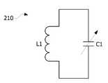
도 3은 본 발명의 한 실시예에 따른 송신 코일의 등가 회로도를 나타낸다.3 shows an equivalent circuit diagram of a transmission coil according to an embodiment of the present invention.
도 3을 참조하면, 송신 코일(210)은 인덕터(L1)와 캐패시터(C1)를 포함하며, 인덕터(L1)의 양단은 캐패시터(C1)의 양단과 연결될 수 있다.3, the
여기서, 캐패시터(C1)는 가변 캐패시터일 수 있으며, 캐패시터(C1)의 캐패시턴스가 조절됨에 따라 임피던스 매칭이 수행될 수 있다. 수신 코일(310)의 등가 회로도도 송신 코일(210)의 등가 회로도와 유사할 수 있으나, 이로 한정되는 것은 아니다.Here, the capacitor C1 may be a variable capacitor, and the impedance matching may be performed as the capacitance of the capacitor C1 is adjusted. The equivalent circuit diagram of the receiving
도 4는 본 발명의 한 실시예에 따른 전원과 무선 전력 송신 장치의 등가 회로도를 나타낸다.4 is an equivalent circuit diagram of a power supply and a wireless power transmission apparatus according to an embodiment of the present invention.
도 4를 참조하면, 송신 코일(210)은 인덕턴스 값과 캐패시턴스 값을 갖는 인덕터(L1)와 캐패시터(C1)를 포함할 수 있다.Referring to FIG. 4, the
도 5는 본 발명의 한 실시예에 따른 무선 전력 수신 장치의 등가 회로도를 나타낸다.5 is an equivalent circuit diagram of a wireless power receiving apparatus according to an embodiment of the present invention.
도 5를 참조하면, 수신 코일(310)은 인덕턴스 값과 캐패시턴스 값을 갖는 인덕터(L2)와 캐패시터(C2)를 포함할 수 있다.5, the receiving
정류부(320)는 수신 코일(310)로부터 전달받은 교류 전력을 직류 전력으로 변환하며, 변환된 직류 전력을 부하단(400)에 전달할 수 있다.The rectifying
구체적으로, 정류부(320)는 도시되지 않았지만 정류기와 평활 회로를 포함할 수 있다. 정류기는, 예를 들면 실리콘 정류기일 수 있고, 다이오드(D1)로 등가화 될 수 있지만, 이로 한정되는 것은 아니다. 정류기는 수신 코일(310)로부터 전달받은 교류 전력을 직류 전력으로 변환할 수 있다. 평활 회로는 정류기에서 변환된 직류 전력에 포함된 교류 성분을 제거하여 매끄러운 직류 전력을 출력할 수 있다. 평활 회로는, 예를 들면 캐패시터(C3)로 등가화될 수 있으나, 이로 한정되는 것은 아니다.Specifically, the
부하단(400)은 배터리 또는 배터리가 내장된 장치일 수 있다.The
한편, 무선 전력 전송에서 품질 지수(Quality Factor)는 중요한 의미를 가진다. 품질 지수(Quality Factor, Q)는 무선 전력 송신 장치(200) 또는 무선 전력 수신 장치(300) 부근에 축적할 수 있는 에너지의 지표를 의미한다. 품질 지수는 동작 주파수(w), 코일의 형상, 치수, 소재 등에 따라 달라질 수 있으며, 아래 수학식 1과 같이 나타낼 수 있다.On the other hand, Quality Factor has important meaning in wireless power transmission. The quality factor (Q) is an index of energy that can be accumulated in the vicinity of the wireless
[수학식 1][Equation 1]
Q=w*Ls/RsQ = w * Ls / Rs
여기서, Ls은 코일의 인덕턴스이고, Rs은 코일자체에서 발생하는 전력손실량에 해당하는 저항을 의미한다.Here, Ls is the inductance of the coil, and Rs is the resistance corresponding to the amount of power loss occurring in the coil itself.
품질 지수는 0에서 무한대의 값을 가질 수 있으며, 품질 지수가 클수록 무선 전력 송신 장치(200)와 무선 전력 수신 장치(300)간의 전력 전송 효율이 높은 것으로 볼 수 있다.The quality index can have a value from 0 to infinity and the higher the quality index, the higher the power transmission efficiency between the wireless
본 발명의 한 실시예에 따르면, 접착층에 자성체를 포함시켜, 코일의 인덕턴스를 높이고자 한다.According to one embodiment of the present invention, a magnetic substance is included in the adhesive layer to increase the inductance of the coil.
도 6은 본 발명의 한 실시예에 따른 무선 전력 송신 장치에 포함되는 연자성층 및 송신 코일의 상면도이다.6 is a top view of a soft magnetic layer and a transmission coil included in a wireless power transmission apparatus according to an embodiment of the present invention.
도 6을 참조하면, 연자성층(600) 상에 송신 코일(610)이 형성된다. 송신 코일(610)은 평면 상에 스파이럴(spiral) 또는 헬리컬(helical) 형상으로 권선(wire wound)된 형태일 수 있다. 송신 코일(610)은 라운드(round) 형상, 레이스트랙(racetrack) 형상, 직사각형(rectangular) 형상, 삼각형 형상(triangular), 모서리가 둥근 다각형 형상 등일 수 있으나, 이에 한정되는 것은 아니다.Referring to FIG. 6, a
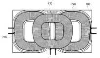
도 7은 본 발명의 다른 실시예에 따른 무선 전력 송신 장치에 포함되는 연자성층 및 송신 코일의 상면도이다.7 is a top view of a soft magnetic layer and a transmission coil included in a wireless power transmission apparatus according to another embodiment of the present invention.
도 7을 참조하면, 연자성층(700) 상에 송신 코일(710, 720, 730)이 형성된다. 각 송신 코일(710, 720, 730)은 평면 상에 스파이럴(spiral) 또는 헬리컬(helical) 형상으로 권선(wire wound)된 형태일 수 있다. 각 송신 코일(710, 720, 730)은 라운드(round) 형상, 레이스트랙(racetrack) 형상, 직사각형(rectangular) 형상, 삼각형 형상(triangular), 모서리가 둥근 다각형 형상 등일 수 있으나, 이에 한정되는 것은 아니다. 송신 코일(710)과 송신 코일(720)은 나란히 배치되며, 송신 코일(730)은 송신 코일(710) 및 송신 코일(720) 상에 배치될 수 있다.7, transmitting
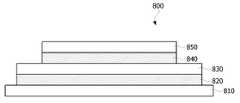
도 8은 본 발명의 한 실시예에 따른 무선 전력 송신 장치의 단면도이고, 도 9는 본 발명의 한 실시예에 따른 무선 전력 송신 장치에 포함되는 접착층의 단면도이다.FIG. 8 is a cross-sectional view of a wireless power transmission apparatus according to an embodiment of the present invention, and FIG. 9 is a cross-sectional view of an adhesive layer included in a wireless power transmission apparatus according to an embodiment of the present invention.
도 8을 참조하면, 무선 전력 송신 장치(800)는 기판(810), 기판(810) 상에 형성되는 제1 접착층(820), 제1 접착층(820) 상에 형성되는 연자성층(830), 연자성층(830) 상에 형성되는 제2 접착층(840), 제2 접착층(840) 상에 형성되는 송신 코일(850)을 포함한다.8, a wireless
기판(810)은 플라스틱 소재의 기판 또는 금속 소재의 기판일 수 있다. 기판(810)은 PCB(Printed Circuit Board)일 수도 있다. 기판(810)은 무선 전력 송신 장치(800)의 케이스일 수도 있다. 이에 따라, 기판(810)은 기구물과 혼용될 수 있다.The
연자성층(830)은 소결체(pellet), 플레이트(plate), 시트(sheet), 리본(ribbon), 호일(foil), 필름(film) 등의 다양한 형태로 구현될 수 있다. 일 예로, 연자성층(830)은 단일 금속 또는 합금 분말 플레이크 및 고분자 수지를 포함하는 복합체(composite)를 포함할 수 있다. 여기서, 합금 분말 플레이크는 Fe, Co 및 Ni의 합금 분말 클레이크 및 Fe, Si 및 Cr의 합금 분말 플레이크 중 적어도 하나를 포함할 수 있으나, 이에 한정되는 것은 아니다. 그리고, 고분자 수지는 PV(polyvinyl)계 수지, PE(polyethylene)계 수지 및 PP(polypropylene)계 수지 중 적어도 하나를 포함할 수 있으나, 이에 한정되는 것은 아니다.The soft
연자성층(830) 상에는 송신 코일(850)이 형성된다. 코일(850)은 연자성층(830) 상에서 연자성층(830)의 평면과 평행한 방향으로 감겨질 수 있다. 도시되지 않았으나, 송신 코일(850) 상에는 지지 필름이 더 형성될 수 있다. 지지 필름은 송신 코일(850)을 지지하기 위한 것으로, PET(polyethylene terephthalate) 소재를 포함할 수 있다.A
한편, 제1 접착층(820)은 기판(810)과 연자성층(830) 사이에 형성되며, 기판(810)과 연자성층(830)을 접착시킨다. 그리고, 제2 접착층(840)은 연자성층(830)과 송신 코일(850) 사이에 형성되며, 연자성층(830)과 송신 코일(850)을 접착시킨다. 이때, 제1 접착층(820) 및 제2 접착층(840) 중 적어도 하나는 자성체를 포함한다. 제1 접착층(820) 및 제2 접착층(840) 중 적어도 하나가 자성체를 포함하면, 무선 전력 송신 장치(800)의 실효 투자율을 높이고, 인덕턴스를 증가시킬 수 있다.The first
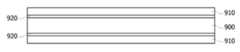
도 9를 참조하면, 제1 접착층(820) 및 제2 접착층(840) 중 적어도 하나는 자성층(900) 및 자성층의 양 면에 형성되는 접착제(910)를 포함한다.9, at least one of the first
자성층(900)은 고투자율의 자성체를 포함하는 자성 시트, 자성 필름, 자성 호일 등일 수 있다. 여기서, 고투자율의 자성체는, 예를 들면 센더스트(sendust), 퍼멀로이(permalloy), MPP(Molybdenum Permally Powder) 등일 수 있으나, 이에 한정되는 것은 아니다. 센더스트는 Fe-Si-Al의 3원계 합금을 의미한다. 퍼멀로이는 Ni-Fe의 2원계 합금을 의미한다. 자성층(900)의 초투자율은 500μ' 이상일 수 있으며, 연자성층(830)과의 초투자율 차가 100 내지 300kHz에서 100 μ' 이상일 수 있다. 여기서, 자성층(900)은 기판(810)과 연자성층(830) 또는 연자성층(830)과 코일(850)을 접착하는 일반적인 양면 테이프의 기재를 대체할 수 있다. 이에 따라, 무선 전력 송신 장치 또는 무선 전력 수신 장치의 전체적인 두께를 증가시키지 않으면서도, 실효 투자율을 증가시켜 인덕턴스를 높일 수 있다.The
이때, 자성층(900)과 접착제(910) 사이에는 금속 리본(ribbon)이 더 형성될 수도 있다. 금속 리본은 투자율이 매우 높으므로, 무선 전력 송신 장치의 전체적인 두께를 거의 증가시키지 않으면서도, 실효 투자율을 더욱 증가시켜 인덕턴스를 높일 수 있다.At this time, a metal ribbon may be further formed between the
한편, 자성층(900)의 투자율이 연자성층(830)의 투자율보다 높은 경우, 제1 접착층(820) 또는 제2 접착층(840)과 연자성층(830) 간의 통전으로 인하여 전자기 성분이 상쇄될 수 있다. 이에 따라, 접착제(910)는 절연 물질을 포함할 수 있다. 예를 들어, 접착제(910)는 아크릴레이트(acrylate)계 유기 접착제, 에폭시(epoxy)계 유기 접착제, 실리콘(silicon)계 유기 접착제 등을 포함할 수 있다.On the other hand, when the magnetic permeability of the
또는, 제1 접착층(820) 또는 제2 접착층(840)의 표면은 SiO2등으로 성막처리될 수도 있다. 이에 따라, 제1 접착층(820) 또는 제2 접착층(840)과 연자성층(830)은 절연될 수 있다.Alternatively, the surfaces of the first
이하, 본 발명의 한 실시예에 따른 무선 전력 송신 장치의 인덕턴스에 대한 실험 결과를 설명한다.Hereinafter, experimental results of inductance of a wireless power transmission apparatus according to an embodiment of the present invention will be described.
도 10은 접착층이 자성체를 포함하지 않는 경우 투자율 증가에 따른 인덕턴스 증가율을 설명하는 그래프이고, 도 11은 접착층이 자성체를 포함하지 않는 경우 두께 증가에 따른 인덕턴스 증가율을 설명하는 그래프이다.FIG. 10 is a graph for explaining the inductance increase rate due to an increase in permeability when the adhesive layer does not include a magnetic body, and FIG. 11 is a graph for explaining the inductance increase rate according to an increase in thickness when the adhesive layer does not include a magnetic body.
도 10 내지 11을 참조하면, 투자율(μ', permeability) 또는 두께의 증가에 따라 일정 수준까지는 인덕턴스가 증가하지만, 일정 수준에 도달한 후에는 더 이상 증가하지 않고 포화된다.Referring to FIGS. 10 to 11, the inductance increases to a certain level as the permeability (or permeability) or thickness increases. However, after reaching a certain level, the inductance is not increased but saturates.
도 12는 본 발명의 한 실시예에 따라 접착층이 자성체를 포함하는 경우 두께 증가에 따른 인덕턴스 증가율을 설명하는 그래프이다.12 is a graph illustrating the inductance increase rate with increasing thickness when the adhesive layer includes a magnetic substance according to an embodiment of the present invention.
여기서, 기판, 연자성층 및 코일이 순차로 적층되어 있고, 기판과 연자성층 사이 및 연자성층과 코일 사이에는 접착층이 형성되어 있다. 투자율(μ)이 26이고 두께가 2.0mm인 연자성층이 사용되었으며, 연자성층과 코일 사이의 접착층은 0.1mm로 고정시켰다.Here, the substrate, the soft magnetic layer, and the coil are sequentially laminated, and an adhesive layer is formed between the substrate and the soft magnetic layer and between the soft magnetic layer and the coil. A soft magnetic layer having a magnetic permeability (μ) of 26 and a thickness of 2.0 mm was used, and the adhesive layer between the soft magnetic layer and the coil was fixed at 0.1 mm.
접착층이 자성체를 포함하지 않는 경우(normal), 즉 접착층으로 일반적인 양면 테이프를 사용한 경우의 인덕턴스를 측정한 후, 투자율(μ)이 500인 자성체를 포함하고 자성층 및 접착제의 두께 비가 7대 3인 접착층의 두께를 0.1mm 내지 0.4mm까지 증가시켜가며 인덕턴스를 측정하였다.The inductance in the case where the adhesive layer does not include a magnetic substance (normal), that is, when a general double-faced tape is used as the adhesive layer, is measured and then the adhesive layer containing a magnetic material having a permeability (μ) of 500 and having a magnetic layer and an adhesive thickness ratio of 7: And the inductance was measured while increasing the thickness from 0.1 mm to 0.4 mm.
도 12에서 나타난 바와 같이, 접착층이 자성체를 포함하는 경우(약 11.4), 자성체를 포함하지 않는 경우(약 11.2)에 비하여 인덕턴스가 높음을 알 수 있다. 또한, 자성체를 포함하는 접착층이 두꺼워지더라도 인덕턴스가 포화되지 않고, 증가함을 알 수 있다.As shown in FIG. 12, it can be seen that the inductance is higher than when the adhesive layer contains a magnetic material (about 11.4) and does not include a magnetic material (about 11.2). It can also be seen that the inductance is not saturated and increases even if the thickness of the adhesive layer containing the magnetic substance is increased.
이와 같이, 본 발명의 한 실시예에 따르면 높은 인덕턴스를 가지는 무선 전력 송신 장치를 얻을 수 있다. 또한, 접착층의 두께를 조절하여 원하는 수준의 인덕턴스를 얻을 수도 있다.As described above, according to the embodiment of the present invention, a wireless power transmission apparatus having a high inductance can be obtained. Further, the thickness of the adhesive layer can be adjusted to obtain a desired level of inductance.
이상에서 설명의 편의를 위하여 무선 전력 송신 장치를 예로 들어 설명하나, 이에 한정되는 것은 아니다. 본 발명의 실시예는 무선 전력 수신 장치의 기판, 연자성층 및 코일 사이에 형성되는 접착층에도 동일하게 적용될 수 있다. 또한, 무선 전력 수신 장치가 WPC 기능과 NFC 기능을 동시에 가지는 경우, 연자성층 상에는 NFC 코일이 더 적층될 수 있다. NFC 코일은 수신 코일의 바깥을 둘러싸도록 형성될 수 있다.For convenience of description, the wireless power transmission apparatus is described as an example, but the present invention is not limited thereto. Embodiments of the present invention are equally applicable to a substrate, a soft magnetic layer, and an adhesive layer formed between coils of a wireless power receiving apparatus. Further, when the wireless power receiving apparatus has both the WPC function and the NFC function, the NFC coil may be further stacked on the soft magnetic layer. The NFC coil may be formed so as to surround the outside of the receiving coil.
상기에서는 본 발명의 바람직한 실시예를 참조하여 설명하였지만, 해당 기술 분야의 숙련된 당업자는 하기의 특허 청구의 범위에 기재된 본 발명의 사상 및 영역으로부터 벗어나지 않는 범위 내에서 본 발명을 다양하게 수정 및 변경시킬 수 있음을 이해할 수 있을 것이다.It will be apparent to those skilled in the art that various modifications and variations can be made in the present invention without departing from the spirit or scope of the present invention as defined by the following claims It can be understood that
10: 무선 충전 시스템
100: 전원
200: 무선 전력 송신 장치
300: 무선 전력 수신 장치
810: 기판
820, 840: 접착층
830: 연자성층
850: 코일10: Wireless charging system
100: Power supply
200: Wireless power transmitting device
300: Wireless power receiving device
810: substrate
820, 840: adhesive layer
830: soft magnetic layer
850: Coil
Claims (11)
Translated fromKorean기판,
상기 기판 상에 형성되는 제1 접착층,
상기 제1 접착층 상에 형성되는 연자성층,
상기 연자성층 상에 형성되는 제2 접착층,
상기 제2 접착층 상에 형성되는 송신 코일을 포함하고,
상기 제1 접착층 및 상기 제2 접착층 중 적어도 하나는 자성체를 포함하는 무선 전력 송신 장치.A wireless power transmission apparatus of a wireless charging system,
Board,
A first adhesive layer formed on the substrate,
A soft magnetic layer formed on the first adhesive layer,
A second adhesive layer formed on the soft magnetic layer,
And a transmission coil formed on the second adhesive layer,
Wherein at least one of the first adhesive layer and the second adhesive layer includes a magnetic substance.
상기 제1 접착층 및 상기 제2 접착층 중 적어도 하나는
자성체를 포함하는 자성층, 그리고
상기 자성층의 양 면에 형성되는 접착제
를 포함하는 무선 전력 송신 장치.The method according to claim 1,
Wherein at least one of the first adhesive layer and the second adhesive layer comprises
A magnetic layer including a magnetic body, and
The adhesive formed on both surfaces of the magnetic layer
And a wireless power transmitter.
상기 자성층은 센더스트(sendust), 퍼멀로이(permalloy) 및 MPP(Molybdenum Permally Powder) 중 적어도 하나를 포함하는 무선 전력 송신 장치.3. The method of claim 2,
Wherein the magnetic layer comprises at least one of sendust, permalloy, and molybdenum permally powder (MPP).
상기 자성층과 상기 접착제 사이에 금속 리본이 더 형성되는 무선 전력 송신 장치.3. The method of claim 2,
And a metal ribbon is further formed between the magnetic layer and the adhesive.
상기 접착제는 절연 물질을 포함하는 무선 전력 송신 장치.3. The method of claim 2,
Wherein the adhesive comprises an insulating material.
상기 접착층의 표면은 절연 물질로 성막 처리되는 무선 전력 송신 장치.3. The method of claim 2,
Wherein a surface of the adhesive layer is formed by an insulating material.
상기 절연 물질은 SiO2를 포함하는 무선 전력 송신 장치.The method according to claim 6,
The insulating material is wireless power transmission apparatus including a SiO2.
기판,
상기 기판 상에 형성되는 제1 접착층,
상기 제1 접착층 상에 형성되는 연자성층,
상기 연자성층 상에 형성되는 제2 접착층,
상기 제2 접착층 상에 형성되는 수신 코일을 포함하고,
상기 제1 접착층 및 상기 제2 접착층 중 적어도 하나는 자성체를 포함하는 무선 전력 수신 장치.A wireless power receiving apparatus of a wireless charging system,
Board,
A first adhesive layer formed on the substrate,
A soft magnetic layer formed on the first adhesive layer,
A second adhesive layer formed on the soft magnetic layer,
And a receiving coil formed on the second adhesive layer,
Wherein at least one of the first adhesive layer and the second adhesive layer includes a magnetic substance.
자성체를 포함하는 자성층, 그리고
상기 자성층의 양 면에 형성되는 접착제
를 포함하는 접착층.An adhesive layer of a wireless power transmission device or a wireless power reception device,
A magnetic layer including a magnetic body, and
The adhesive formed on both surfaces of the magnetic layer
.
상기 자성층은 센더스트(sendust), 퍼멀로이(permalloy) 및 MPP(Molybdenum Permally Powder) 중 적어도 하나를 포함하는 접착층.10. The method of claim 9,
Wherein the magnetic layer comprises at least one of sendust, permalloy and molybdenum permally powder (MPP).
상기 자성층과 상기 접착제 사이에는 금속 리본이 더 형성되는 접착층.10. The method of claim 9,
And a metal ribbon is further formed between the magnetic layer and the adhesive.
Priority Applications (4)
| Application Number | Priority Date | Filing Date | Title |
|---|---|---|---|
| KR1020140130529AKR20160037652A (en) | 2014-09-29 | 2014-09-29 | Wireless power transmitting apparatus and wireless power receiving apparatus |
| US15/515,022US11146092B2 (en) | 2014-09-29 | 2015-09-08 | Wireless power transmitting apparatus and wireless power receiving apparatus |
| PCT/KR2015/009462WO2016052879A1 (en) | 2014-09-29 | 2015-09-08 | Wireless power transmitting apparatus and wireless power receiving apparatus |
| US16/520,111US20190348854A1 (en) | 2014-09-29 | 2019-07-23 | Wireless power transmitting apparatus and wireless power receiving apparatus |
Applications Claiming Priority (1)
| Application Number | Priority Date | Filing Date | Title |
|---|---|---|---|
| KR1020140130529AKR20160037652A (en) | 2014-09-29 | 2014-09-29 | Wireless power transmitting apparatus and wireless power receiving apparatus |
Publications (1)
| Publication Number | Publication Date |
|---|---|
| KR20160037652Atrue KR20160037652A (en) | 2016-04-06 |
Family
ID=55630861
Family Applications (1)
| Application Number | Title | Priority Date | Filing Date |
|---|---|---|---|
| KR1020140130529ACeasedKR20160037652A (en) | 2014-09-29 | 2014-09-29 | Wireless power transmitting apparatus and wireless power receiving apparatus |
Country Status (3)
| Country | Link |
|---|---|
| US (2) | US11146092B2 (en) |
| KR (1) | KR20160037652A (en) |
| WO (1) | WO2016052879A1 (en) |
Cited By (1)
| Publication number | Priority date | Publication date | Assignee | Title |
|---|---|---|---|---|
| WO2018147649A1 (en)* | 2017-02-10 | 2018-08-16 | 엘지이노텍(주) | Magnetic sheet and wireless power reception device comprising same |
Families Citing this family (5)
| Publication number | Priority date | Publication date | Assignee | Title |
|---|---|---|---|---|
| KR20180041869A (en)* | 2016-10-17 | 2018-04-25 | 엘지이노텍 주식회사 | Wireless charging apparatus and system for transport device |
| DE102016222529A1 (en)* | 2016-11-16 | 2018-05-17 | Robert Bosch Gmbh | Device for an inductive energy transmission system, inductive energy transmission system and charging device for an electrical energy storage device |
| WO2020092478A1 (en)* | 2018-10-31 | 2020-05-07 | Research Triangle Institute | Electrically conductive membrane assembly and related systems and methods |
| US11380480B2 (en) | 2019-07-10 | 2022-07-05 | Lear Corporation | Strip induction coil for wireless charging of a vehicle battery |
| US11007887B2 (en) | 2019-07-11 | 2021-05-18 | Lear Corporation | Tubular induction coil for wireless charging of a vehicle battery |
Family Cites Families (76)
| Publication number | Priority date | Publication date | Assignee | Title |
|---|---|---|---|---|
| US4023057A (en)* | 1974-03-22 | 1977-05-10 | Pacific Textile & Chemical Corporation | Electric motor field magnets |
| MX174055B (en)* | 1990-02-06 | 1994-04-18 | Bell Helicopter Textron Inc | ELECTROMAGNETIC WAVES ATTENUATING STRUCTURE AND DEFROSTER |
| KR960006848B1 (en)* | 1990-05-31 | 1996-05-23 | 가부시끼가이샤 도시바 | Planar magnetic elements |
| US5371486A (en)* | 1990-09-07 | 1994-12-06 | Kabushiki Kaisha Toshiba | Transformer core |
| US6781926B2 (en)* | 2000-10-10 | 2004-08-24 | Hitachi Maxell, Limited | Magneto-optical head having heat sink layer |
| JP3724405B2 (en)* | 2001-10-23 | 2005-12-07 | 株式会社村田製作所 | Common mode choke coil |
| EP1453368A4 (en)* | 2001-11-09 | 2008-04-09 | Tdk Corp | Composite magnetic element, electromagnetic wave absorbing sheet, production method for sheet-form article, production method for electromagnetic wave absorbing sheet |
| JP2004235355A (en)* | 2003-01-29 | 2004-08-19 | Tdk Corp | Soft magnetic member and magnetic element using same |
| JP2005080023A (en)* | 2003-09-01 | 2005-03-24 | Sony Corp | Magnetic core member, antenna module and portable communication terminal provided with the same |
| CN100514604C (en)* | 2004-03-12 | 2009-07-15 | 株式会社半导体能源研究所 | Semiconductor device with a plurality of transistors |
| US7161550B2 (en)* | 2004-04-20 | 2007-01-09 | Tdk Corporation | Dual- and quad-ridged horn antenna with improved antenna pattern characteristics |
| US8112157B2 (en)* | 2005-05-27 | 2012-02-07 | California Institute Of Technology | Magnetic material-containing microfabricated devices for wireless data and power transfer |
| CN101278398B (en)* | 2005-09-30 | 2010-09-29 | 株式会社半导体能源研究所 | Method for manufacturing semiconductor device |
| WO2007063884A1 (en)* | 2005-11-30 | 2007-06-07 | Holy Loyalty International Co., Ltd. | Surface inductor device |
| EP2028663A4 (en)* | 2006-03-29 | 2011-12-07 | Hitachi Metals Ltd | COIL COMPONENT AND METHOD OF MANUFACTURE |
| EP2082468A2 (en)* | 2006-10-26 | 2009-07-29 | Koninklijke Philips Electronics N.V. | Floor covering and inductive power system |
| WO2008090852A1 (en)* | 2007-01-24 | 2008-07-31 | Murata Manufacturing Co., Ltd. | Multilayer coil part and its manufacturing method |
| KR101485926B1 (en)* | 2007-02-02 | 2015-02-04 | 가부시키가이샤 한도오따이 에네루기 켄큐쇼 | Memory device |
| JP4867698B2 (en)* | 2007-02-20 | 2012-02-01 | Tdk株式会社 | Thin film magnetic device and electronic component module having the same |
| ITTO20070563A1 (en)* | 2007-07-30 | 2009-01-31 | St Microelectronics Srl | RADIOFREQUENCY IDENTIFICATION DEVICE WITH COUPLED ANTENNA IN NEAR FIELD |
| US7795700B2 (en)* | 2008-02-28 | 2010-09-14 | Broadcom Corporation | Inductively coupled integrated circuit with magnetic communication path and methods for use therewith |
| JP5229317B2 (en)* | 2008-04-28 | 2013-07-03 | 株式会社村田製作所 | Multilayer coil component and manufacturing method thereof |
| WO2010090539A1 (en)* | 2009-02-05 | 2010-08-12 | Auckland Uniservices Limited | Inductive power transfer apparatus |
| WO2010089921A1 (en)* | 2009-02-07 | 2010-08-12 | 株式会社 村田製作所 | Method for manufacturing module with planar coil, and module with planar coil |
| JP5339974B2 (en)* | 2009-03-11 | 2013-11-13 | 新光電気工業株式会社 | Inductor device and manufacturing method thereof |
| US20110123783A1 (en)* | 2009-11-23 | 2011-05-26 | David Sherrer | Multilayer build processses and devices thereof |
| US9030159B2 (en)* | 2010-03-26 | 2015-05-12 | Boston Scientific Neuromodulation Corporation | Inductive charger with magnetic shielding |
| US8934857B2 (en) | 2010-05-14 | 2015-01-13 | Qualcomm Incorporated | Controlling field distribution of a wireless power transmitter |
| CN103168405A (en)* | 2010-08-25 | 2013-06-19 | 捷通国际有限公司 | Wireless power supply system and multi-layer shim assembly |
| CN103081293B (en)* | 2010-09-03 | 2016-02-03 | 富士通株式会社 | Wireless power transmission device |
| US8803751B1 (en)* | 2010-09-20 | 2014-08-12 | The Boeing Company | Multiferroic antenna and transmitter |
| JP5581163B2 (en)* | 2010-09-30 | 2014-08-27 | 日東電工株式会社 | EMI shielding sheet for wireless power transmission |
| US8505192B2 (en)* | 2010-10-08 | 2013-08-13 | Advance Furnace Systems Corp. | Manufacturing method of common mode filter |
| WO2012050037A1 (en)* | 2010-10-12 | 2012-04-19 | 株式会社村田製作所 | Antenna apparatus and communication terminal apparatus |
| WO2012053439A1 (en)* | 2010-10-21 | 2012-04-26 | Tdk株式会社 | Coil component and method for producing same |
| US9178369B2 (en)* | 2011-01-18 | 2015-11-03 | Mojo Mobility, Inc. | Systems and methods for providing positioning freedom, and support of different voltages, protocols, and power levels in a wireless power system |
| JP2012204440A (en) | 2011-03-24 | 2012-10-22 | Nitto Denko Corp | Magnetic element for wireless power transmission and manufacturing method of the same |
| TWI447753B (en)* | 2011-07-07 | 2014-08-01 | Inpaq Technology Co Ltd | Common mode filter having heterogeneous laminates and method of manufacturing the same |
| KR101213090B1 (en)* | 2011-07-14 | 2012-12-18 | 유한회사 한림포스텍 | Core assembly for wireless power transmission apparatus and wireless power transmission apparatus having the same |
| US9251458B2 (en)* | 2011-09-11 | 2016-02-02 | Féinics Amatech Teoranta | Selective deposition of magnetic particles and using magnetic material as a carrier medium to deposit nanoparticles |
| JP5853199B2 (en)* | 2011-08-25 | 2016-02-09 | パナソニックIpマネジメント株式会社 | Metallic foreign matter detection method for non-contact power feeding system, non-contact power feeding device, power receiving device provided in electrical equipment, and non-contact power feeding system |
| CN103764592B (en)* | 2011-09-02 | 2016-04-20 | 株式会社村田制作所 | Ferrite ceramic composition, ceramic electronic component, and method for producing ceramic electronic component |
| CN103918048B (en)* | 2011-11-08 | 2016-09-28 | 株式会社东芝 | Noncontact current-collecting device sheet magnetic material and noncontact current-collecting device, electronic equipment and the non-contact charging device of this sheet magnetic material of use |
| US20130119511A1 (en)* | 2011-11-10 | 2013-05-16 | Taiwan Semiconductor Manufacturing Company, Ltd. | Inductor having bond-wire and manufacturing method thereof |
| US9252611B2 (en)* | 2011-12-21 | 2016-02-02 | Amosense Co., Ltd. | Magnetic field shielding sheet for a wireless charger, method for manufacturing same, and receiving apparatus for a wireless charger using the sheet |
| WO2013099540A1 (en)* | 2011-12-27 | 2013-07-04 | 株式会社村田製作所 | Laminated common-mode choke coil |
| JP5807685B2 (en) | 2012-01-31 | 2015-11-10 | 富士通株式会社 | Power receiving device and power supply system |
| JP5915667B2 (en) | 2012-01-31 | 2016-05-11 | 富士通株式会社 | Power transmission device, power transmission system, and power transmission method |
| JP5621946B2 (en)* | 2012-02-29 | 2014-11-12 | 株式会社村田製作所 | Multilayer inductor and power circuit module |
| KR101531082B1 (en)* | 2012-03-12 | 2015-07-06 | 삼성전기주식회사 | Common mode filter and method of manufacturing the same |
| JP5648768B2 (en)* | 2012-03-16 | 2015-01-07 | 株式会社村田製作所 | Common mode choke coil |
| JP5045858B1 (en) | 2012-04-12 | 2012-10-10 | パナソニック株式会社 | Non-contact charging module manufacturing method and non-contact charging module |
| CN103620869B (en)* | 2012-04-27 | 2016-06-22 | 株式会社村田制作所 | Coil antenna and communication terminal |
| US9432090B2 (en) | 2012-05-08 | 2016-08-30 | Lockheed Martin Corporation | Wireless power transmission system |
| JPWO2013172349A1 (en)* | 2012-05-14 | 2016-01-12 | 日立化成株式会社 | Antenna sheet for non-contact charging device and charging device using the sheet |
| US8824161B2 (en)* | 2012-06-15 | 2014-09-02 | Medtronic, Inc. | Integrated circuit packaging for implantable medical devices |
| JP5967028B2 (en)* | 2012-08-09 | 2016-08-10 | 株式会社村田製作所 | ANTENNA DEVICE, WIRELESS COMMUNICATION DEVICE, AND ANTENNA DEVICE MANUFACTURING METHOD |
| DE112013004520T5 (en) | 2012-09-18 | 2015-06-03 | Panasonic Intellectual Property Management Co., Ltd. | System for contactless electrical power supply |
| KR101912268B1 (en) | 2012-10-16 | 2018-10-29 | 삼성전기 주식회사 | Magnetic sheet for wireless charging element and manufacturing method of the same |
| JP6038172B2 (en)* | 2012-11-15 | 2016-12-07 | シャープ株式会社 | Liquid crystal module and electronic equipment |
| JP6050667B2 (en)* | 2012-12-04 | 2016-12-21 | デクセリアルズ株式会社 | Coil module, non-contact power transmission antenna unit, and electronic device |
| KR101476044B1 (en)* | 2012-12-06 | 2014-12-23 | 쓰리엠 이노베이티브 프로퍼티즈 캄파니 | Ferrite Green Sheet, Sintered Ferrite Sheet, Ferrite Complex Sheet Comprising the Same, and Conductive Loop Antenna Module |
| US9812774B2 (en)* | 2013-03-05 | 2017-11-07 | Amosense Co., Ltd. | Composite sheet for shielding magnetic field and electromagnetic wave, and antenna module comprising same |
| JP5823433B2 (en)* | 2013-03-13 | 2015-11-25 | 株式会社東芝 | Wireless power feeding system, power transmission unit, power reception unit, power transmission control device, and power reception control device |
| EP2984731B8 (en)* | 2013-03-15 | 2019-06-26 | Tc1 Llc | Malleable tets coil with improved anatomical fit |
| KR101394508B1 (en) | 2013-03-22 | 2014-05-13 | 엘지이노텍 주식회사 | Soft magnetism sheet, wireless power receiving apparatus and wireless charging method of the same |
| KR20140134444A (en)* | 2013-05-14 | 2014-11-24 | 삼성전기주식회사 | Magnetic sheet and noncontact charging apparatus using the same |
| KR102086345B1 (en)* | 2013-07-01 | 2020-03-09 | 엘지전자 주식회사 | Wireless power transmitting apparatus |
| KR20150010519A (en)* | 2013-07-19 | 2015-01-28 | 삼성전자주식회사 | Soft magnetic exchange coupled composite structure, high frequency device components comprising the same, antenna module comprising the same, and magnetoresistive device comprising the same |
| WO2015050369A1 (en)* | 2013-10-02 | 2015-04-09 | 엘지이노텍 주식회사 | Magnetic member and wireless power transmission device comprising same |
| JP6138032B2 (en)* | 2013-11-21 | 2017-05-31 | 株式会社ThruChip Japan | Integrated circuit and laminated circuit including the same |
| KR101922871B1 (en)* | 2013-11-29 | 2018-11-28 | 삼성전기 주식회사 | Multilayered electronic component, manufacturing method thereof and board having the same mounted thereon |
| US10083792B2 (en)* | 2014-05-14 | 2018-09-25 | Qualcomm Incorporated | System, method and apparatus for reducing the height of bipolar transmitters and/or receivers in electric vehicle charging |
| US9929569B2 (en) | 2014-11-07 | 2018-03-27 | The Boeing Company | Methods for steering a magnetic field for smart wireless power transmission |
| US9912172B2 (en)* | 2015-01-14 | 2018-03-06 | Qualcomm Incorporated | Asymmetrically layered stacked coils and/or chamfered ferrite in wireless power transfer applications |
| US20160308402A1 (en)* | 2015-04-20 | 2016-10-20 | Babak Alavikia | Electromagnetic Energy Harvesting Using Complementary Split-Ring Resonators |
- 2014
- 2014-09-29KRKR1020140130529Apatent/KR20160037652A/ennot_activeCeased
- 2015
- 2015-09-08WOPCT/KR2015/009462patent/WO2016052879A1/enactiveApplication Filing
- 2015-09-08USUS15/515,022patent/US11146092B2/enactiveActive
- 2019
- 2019-07-23USUS16/520,111patent/US20190348854A1/ennot_activeAbandoned
Cited By (3)
| Publication number | Priority date | Publication date | Assignee | Title |
|---|---|---|---|---|
| WO2018147649A1 (en)* | 2017-02-10 | 2018-08-16 | 엘지이노텍(주) | Magnetic sheet and wireless power reception device comprising same |
| CN110313043A (en)* | 2017-02-10 | 2019-10-08 | Lg伊诺特有限公司 | Magnetic sheet and wireless power receiving device including the same |
| US10868445B2 (en) | 2017-02-10 | 2020-12-15 | Lg Innotek Co., Ltd. | Magnetic sheet and wireless power reception device comprising same |
Also Published As
| Publication number | Publication date |
|---|---|
| WO2016052879A1 (en) | 2016-04-07 |
| US11146092B2 (en) | 2021-10-12 |
| US20170222472A1 (en) | 2017-08-03 |
| US20190348854A1 (en) | 2019-11-14 |
Similar Documents
| Publication | Publication Date | Title |
|---|---|---|
| JP6085326B2 (en) | Wireless power transmitter | |
| CN107078551B (en) | Receiving antenna and wireless power receiving device including the same | |
| TWI539709B (en) | Wireless power feeding system | |
| KR101890326B1 (en) | Wireless power transfer module and portable auxiliary battery including the same | |
| KR20160037652A (en) | Wireless power transmitting apparatus and wireless power receiving apparatus | |
| US9847675B2 (en) | Power receiving device and power feeding system | |
| WO2013172349A1 (en) | Antenna sheet for contactless charging device and charging device using said sheet | |
| JP2014107539A (en) | Magnetic body sheet for non-contact power transmission apparatus | |
| KR102017669B1 (en) | Coil type unit for wireless power transmission, wireless power transmission device, electronic device and manufacturing method of coil type unit for wireless power transmission | |
| US9502173B2 (en) | Shield part, method of fabricating the same, and contactless power transmission device having the shield part | |
| JP2014132658A (en) | Soft magnetic layer, and receiver antenna and radio power receiver having the same | |
| KR101431983B1 (en) | Coil type unit for wireless power transmission, wireless power transmission device, electronic device and manufacturing method of coil type unit for wireless power transmission | |
| CN107431387A (en) | Wireless power reception device and the wireless power induction system for including it | |
| CN204794286U (en) | Wireless charging device and system | |
| CN105340128A (en) | Receiving antenna and wireless power receiving device including the receiving antenna | |
| KR20160105079A (en) | Wireless power receiving apparatus and wireless power transmitting system comprising the same | |
| KR102348411B1 (en) | Shielding unit for complex-antenna unit and complex-transmission module comprising the same | |
| CN204835717U (en) | Thin film coil element and flexible wireless charging device and system applicable to same | |
| CN204835719U (en) | wireless charging device | |
| US9761371B2 (en) | Coil type unit for wireless power transmission, wireless power transmission device, electronic device and manufacturing method of coil type unit for wireless power transmission | |
| KR101888353B1 (en) | Combo antenna module and mobile electronic device having the same | |
| KR20150120216A (en) | Wireless power transmitting apparatus | |
| WO2013022255A2 (en) | High efficiency wireless charger | |
| KR20170086978A (en) | Wireless power receiver and method of manufacturing the same |
Legal Events
| Date | Code | Title | Description |
|---|---|---|---|
| PA0109 | Patent application | Patent event code:PA01091R01D Comment text:Patent Application Patent event date:20140929 | |
| PG1501 | Laying open of application | ||
| A201 | Request for examination | ||
| PA0201 | Request for examination | Patent event code:PA02012R01D Patent event date:20190923 Comment text:Request for Examination of Application Patent event code:PA02011R01I Patent event date:20140929 Comment text:Patent Application | |
| E902 | Notification of reason for refusal | ||
| PE0902 | Notice of grounds for rejection | Comment text:Notification of reason for refusal Patent event date:20201105 Patent event code:PE09021S01D | |
| E601 | Decision to refuse application | ||
| PE0601 | Decision on rejection of patent | Patent event date:20210510 Comment text:Decision to Refuse Application Patent event code:PE06012S01D Patent event date:20201105 Comment text:Notification of reason for refusal Patent event code:PE06011S01I | |
| PN2301 | Change of applicant | Patent event date:20210517 Comment text:Notification of Change of Applicant Patent event code:PN23011R01D |