KR20160036715A - Display device - Google Patents
Display deviceDownload PDFInfo
- Publication number
- KR20160036715A KR20160036715AKR1020140128256AKR20140128256AKR20160036715AKR 20160036715 AKR20160036715 AKR 20160036715AKR 1020140128256 AKR1020140128256 AKR 1020140128256AKR 20140128256 AKR20140128256 AKR 20140128256AKR 20160036715 AKR20160036715 AKR 20160036715A
- Authority
- KR
- South Korea
- Prior art keywords
- display panel
- substrate
- display device
- elastic member
- disposed
- Prior art date
- Legal status (The legal status is an assumption and is not a legal conclusion. Google has not performed a legal analysis and makes no representation as to the accuracy of the status listed.)
- Abandoned
Links
- 239000000758substrateSubstances0.000claimsabstractdescription78
- 239000000853adhesiveSubstances0.000claimsdescription22
- 230000001070adhesive effectEffects0.000claimsdescription22
- 229910052751metalInorganic materials0.000claimsdescription13
- 239000002184metalSubstances0.000claimsdescription13
- 229920003229poly(methyl methacrylate)Polymers0.000claimsdescription8
- 229920000139polyethylene terephthalatePolymers0.000claimsdescription8
- 239000005020polyethylene terephthalateSubstances0.000claimsdescription8
- 239000004926polymethyl methacrylateSubstances0.000claimsdescription8
- -1beta-titanumInorganic materials0.000claimsdescription7
- 239000010949copperSubstances0.000claimsdescription6
- 239000002861polymer materialSubstances0.000claimsdescription6
- 229910052782aluminiumInorganic materials0.000claimsdescription5
- XAGFODPZIPBFFR-UHFFFAOYSA-NaluminiumChemical compound[Al]XAGFODPZIPBFFR-UHFFFAOYSA-N0.000claimsdescription5
- 238000000034methodMethods0.000claimsdescription5
- 239000011347resinSubstances0.000claimsdescription5
- 229920005989resinPolymers0.000claimsdescription5
- 239000010935stainless steelSubstances0.000claimsdescription5
- 229910001220stainless steelInorganic materials0.000claimsdescription5
- 229920002125Sokalan®Polymers0.000claimsdescription4
- 229920000058polyacrylatePolymers0.000claimsdescription4
- 239000004584polyacrylic acidSubstances0.000claimsdescription4
- RYGMFSIKBFXOCR-UHFFFAOYSA-NCopperChemical compound[Cu]RYGMFSIKBFXOCR-UHFFFAOYSA-N0.000claimsdescription3
- 229920001651CyanoacrylatePolymers0.000claimsdescription3
- MWCLLHOVUTZFKS-UHFFFAOYSA-NMethyl cyanoacrylateChemical compoundCOC(=O)C(=C)C#NMWCLLHOVUTZFKS-UHFFFAOYSA-N0.000claimsdescription3
- ZOKXTWBITQBERF-UHFFFAOYSA-NMolybdenumChemical compound[Mo]ZOKXTWBITQBERF-UHFFFAOYSA-N0.000claimsdescription3
- 229910045601alloyInorganic materials0.000claimsdescription3
- 239000000956alloySubstances0.000claimsdescription3
- 229910052802copperInorganic materials0.000claimsdescription3
- 229910000701elgiloys (Co-Cr-Ni Alloy)Inorganic materials0.000claimsdescription3
- 239000003822epoxy resinSubstances0.000claimsdescription3
- 229910000856hastalloyInorganic materials0.000claimsdescription3
- 229910052750molybdenumInorganic materials0.000claimsdescription3
- 239000011733molybdenumSubstances0.000claimsdescription3
- HLXZNVUGXRDIFK-UHFFFAOYSA-Nnickel titaniumChemical compound[Ti].[Ti].[Ti].[Ti].[Ti].[Ti].[Ti].[Ti].[Ti].[Ti].[Ti].[Ni].[Ni].[Ni].[Ni].[Ni].[Ni].[Ni].[Ni].[Ni].[Ni].[Ni].[Ni].[Ni].[Ni]HLXZNVUGXRDIFK-UHFFFAOYSA-N0.000claimsdescription3
- 229910001000nickel titaniumInorganic materials0.000claimsdescription3
- 229920000647polyepoxidePolymers0.000claimsdescription3
- 229920000098polyolefinPolymers0.000claimsdescription3
- 239000004814polyurethaneSubstances0.000claimsdescription3
- 229910001285shape-memory alloyInorganic materials0.000claimsdescription3
- 229920001187thermosetting polymerPolymers0.000claimsdescription3
- WFKWXMTUELFFGS-UHFFFAOYSA-NtungstenChemical compound[W]WFKWXMTUELFFGS-UHFFFAOYSA-N0.000claimsdescription3
- 229910052721tungstenInorganic materials0.000claimsdescription3
- 239000010937tungstenSubstances0.000claimsdescription3
- 229920002635polyurethanePolymers0.000claimsdescription2
- 229920002050silicone resinPolymers0.000claimsdescription2
- 229920001225polyester resinPolymers0.000claims1
- 239000004645polyester resinSubstances0.000claims1
- 239000000463materialSubstances0.000description11
- 239000004973liquid crystal related substanceSubstances0.000description7
- 230000003287optical effectEffects0.000description6
- 230000007935neutral effectEffects0.000description5
- 238000009792diffusion processMethods0.000description4
- 239000011521glassSubstances0.000description4
- 230000001681protective effectEffects0.000description4
- 229910000838Al alloyInorganic materials0.000description2
- GWEVSGVZZGPLCZ-UHFFFAOYSA-NTitan oxideChemical compoundO=[Ti]=OGWEVSGVZZGPLCZ-UHFFFAOYSA-N0.000description2
- 238000010586diagramMethods0.000description2
- 239000010408filmSubstances0.000description2
- 230000017525heat dissipationEffects0.000description2
- 238000001746injection mouldingMethods0.000description2
- 239000007788liquidSubstances0.000description2
- 230000005855radiationEffects0.000description2
- 239000010409thin filmSubstances0.000description2
- 230000000007visual effectEffects0.000description2
- 239000004925Acrylic resinSubstances0.000description1
- 229920000178Acrylic resinPolymers0.000description1
- JMASRVWKEDWRBT-UHFFFAOYSA-NGallium nitrideChemical compound[Ga]#NJMASRVWKEDWRBT-UHFFFAOYSA-N0.000description1
- BQCADISMDOOEFD-UHFFFAOYSA-NSilverChemical compound[Ag]BQCADISMDOOEFD-UHFFFAOYSA-N0.000description1
- 238000006243chemical reactionMethods0.000description1
- 239000003795chemical substances by applicationSubstances0.000description1
- 230000006835compressionEffects0.000description1
- 238000007906compressionMethods0.000description1
- 239000004020conductorSubstances0.000description1
- 238000005336crackingMethods0.000description1
- 230000005684electric fieldEffects0.000description1
- 238000001125extrusionMethods0.000description1
- 239000003292glueSubstances0.000description1
- 239000011159matrix materialSubstances0.000description1
- 239000007769metal materialSubstances0.000description1
- 230000000116mitigating effectEffects0.000description1
- 238000012986modificationMethods0.000description1
- 230000004048modificationEffects0.000description1
- 239000000178monomerSubstances0.000description1
- 238000000465mouldingMethods0.000description1
- 229920003023plasticPolymers0.000description1
- 239000004033plasticSubstances0.000description1
- 239000004417polycarbonateSubstances0.000description1
- 229920000515polycarbonatePolymers0.000description1
- 229920005749polyurethane resinPolymers0.000description1
- 229910052709silverInorganic materials0.000description1
- 239000004332silverSubstances0.000description1
- 239000002904solventSubstances0.000description1
- 239000004408titanium dioxideSubstances0.000description1
- 238000002834transmittanceMethods0.000description1
Images


Classifications
- G—PHYSICS
- G02—OPTICS
- G02F—OPTICAL DEVICES OR ARRANGEMENTS FOR THE CONTROL OF LIGHT BY MODIFICATION OF THE OPTICAL PROPERTIES OF THE MEDIA OF THE ELEMENTS INVOLVED THEREIN; NON-LINEAR OPTICS; FREQUENCY-CHANGING OF LIGHT; OPTICAL LOGIC ELEMENTS; OPTICAL ANALOGUE/DIGITAL CONVERTERS
- G02F1/00—Devices or arrangements for the control of the intensity, colour, phase, polarisation or direction of light arriving from an independent light source, e.g. switching, gating or modulating; Non-linear optics
- G02F1/01—Devices or arrangements for the control of the intensity, colour, phase, polarisation or direction of light arriving from an independent light source, e.g. switching, gating or modulating; Non-linear optics for the control of the intensity, phase, polarisation or colour
- G02F1/13—Devices or arrangements for the control of the intensity, colour, phase, polarisation or direction of light arriving from an independent light source, e.g. switching, gating or modulating; Non-linear optics for the control of the intensity, phase, polarisation or colour based on liquid crystals, e.g. single liquid crystal display cells
- G02F1/133—Constructional arrangements; Operation of liquid crystal cells; Circuit arrangements
- G02F1/1333—Constructional arrangements; Manufacturing methods
- G02F1/133308—Support structures for LCD panels, e.g. frames or bezels
- G—PHYSICS
- G02—OPTICS
- G02F—OPTICAL DEVICES OR ARRANGEMENTS FOR THE CONTROL OF LIGHT BY MODIFICATION OF THE OPTICAL PROPERTIES OF THE MEDIA OF THE ELEMENTS INVOLVED THEREIN; NON-LINEAR OPTICS; FREQUENCY-CHANGING OF LIGHT; OPTICAL LOGIC ELEMENTS; OPTICAL ANALOGUE/DIGITAL CONVERTERS
- G02F1/00—Devices or arrangements for the control of the intensity, colour, phase, polarisation or direction of light arriving from an independent light source, e.g. switching, gating or modulating; Non-linear optics
- G02F1/01—Devices or arrangements for the control of the intensity, colour, phase, polarisation or direction of light arriving from an independent light source, e.g. switching, gating or modulating; Non-linear optics for the control of the intensity, phase, polarisation or colour
- G02F1/13—Devices or arrangements for the control of the intensity, colour, phase, polarisation or direction of light arriving from an independent light source, e.g. switching, gating or modulating; Non-linear optics for the control of the intensity, phase, polarisation or colour based on liquid crystals, e.g. single liquid crystal display cells
- G02F1/133—Constructional arrangements; Operation of liquid crystal cells; Circuit arrangements
- G02F1/1333—Constructional arrangements; Manufacturing methods
- G—PHYSICS
- G02—OPTICS
- G02F—OPTICAL DEVICES OR ARRANGEMENTS FOR THE CONTROL OF LIGHT BY MODIFICATION OF THE OPTICAL PROPERTIES OF THE MEDIA OF THE ELEMENTS INVOLVED THEREIN; NON-LINEAR OPTICS; FREQUENCY-CHANGING OF LIGHT; OPTICAL LOGIC ELEMENTS; OPTICAL ANALOGUE/DIGITAL CONVERTERS
- G02F2201/00—Constructional arrangements not provided for in groups G02F1/00 - G02F7/00
- G02F2201/50—Protective arrangements
- G02F2201/503—Arrangements improving the resistance to shock
- H—ELECTRICITY
- H05—ELECTRIC TECHNIQUES NOT OTHERWISE PROVIDED FOR
- H05K—PRINTED CIRCUITS; CASINGS OR CONSTRUCTIONAL DETAILS OF ELECTRIC APPARATUS; MANUFACTURE OF ASSEMBLAGES OF ELECTRICAL COMPONENTS
- H05K1/00—Printed circuits
- H05K1/02—Details
- H05K1/0277—Bendability or stretchability details
- H05K1/028—Bending or folding regions of flexible printed circuits
Landscapes
- Physics & Mathematics (AREA)
- Nonlinear Science (AREA)
- Mathematical Physics (AREA)
- Chemical & Material Sciences (AREA)
- Crystallography & Structural Chemistry (AREA)
- General Physics & Mathematics (AREA)
- Optics & Photonics (AREA)
- Liquid Crystal (AREA)
- Devices For Indicating Variable Information By Combining Individual Elements (AREA)
- Engineering & Computer Science (AREA)
- Microelectronics & Electronic Packaging (AREA)
- Electroluminescent Light Sources (AREA)
Abstract
Translated fromKoreanDescription
Translated fromKorean본 발명은 일방향으로 만곡되는 표시 패널을 포함하는 표시 장치에 관한 것으로, 표시 패널에 가해지는 인장 응력을 완화할 수 있는 표시 장치에 관한 것이다.BACKGROUND OF THE INVENTION 1. Field of the Invention [0001] The present invention relates to a display device including a display panel curved in one direction, and relates to a display device capable of alleviating tensile stress applied to the display panel.
표시 장치는 발광 방식에 따라 액정 표시 장치(liquid crystal display, LCD), 유기 발광 표시 장치(organic light emitting diode display, OLED display), 플라즈마 표시 장치(plasma display panel, PDP) 및 전기 영동 표시 장치(electrophoretic display) 등으로 분류된다.The display device may include a liquid crystal display (LCD), an organic light emitting diode (OLED) display, a plasma display panel (PDP), and an electrophoretic display display).
최근 표시 장치의 화면이 대화면화 됨에 따라, 시청자가 화면의 중앙부를 보는 경우와 화면의 좌우 양단을 보는 경우에 있어서 시각차가 커지는 문제가 있었다. 즉, 시청자가 대형 표시 장치의 중앙에 대응하는 위치에서 화면에 표시되는 영상을 볼 때, 화면 중앙부의 영상은 선명하게 인지할 수 있으나 화면 좌우 양단의 영상은 선명하게 인지할 수 없는 문제가 있었다.As the screen of the display device has recently become a large screen, there has been a problem in that the visual difference becomes large when the viewer views the center portion of the screen and when viewing the left and right ends of the screen. That is, when the viewer views the video displayed on the screen at a position corresponding to the center of the large display device, the video at the center of the screen can be clearly recognized, but the video on both sides of the screen can not be clearly recognized.
이러한 시각차를 보상하기 위하여 화면 중앙부를 중심으로 좌우 양단이 오목하게 만곡된 곡면 표시 장치가 개발되었다. 곡면 표시 장치는 가로 길이가 세로 길이보다 길고, 가로 방향으로 만곡된 랜드스케이프(landscape) 타입, 및 가로 길이가 세로 길이보다 짧고, 세로 방향으로 만곡된 포트레이트(portrait) 타입으로 구분될 수 있다.In order to compensate for such a visual difference, a curved surface display device has been developed in which both left and right ends are concavely curved around the center of the screen. The curved surface display device may be classified into a landscape type whose horizontal length is longer than a vertical length and which is curved in a horizontal direction and a portrait type whose width is shorter than a vertical length and which is curved in the vertical direction.
곡면 표시 장치는 곡면(curved) 형태로 제작된 고정 프레임에 평면(flat) 형태로 제작된 표시 패널이 결합되어 제작된다. 표시 패널은 고정 프레임의 형태에 따라 휘어지게 되는데, 이 때 표시 패널의 중립면(Neutral Plane, 中立面)(NP)을 기준으로 상부 기판에 압축 응력(Compressive Stress, CS)이 발생하고, 하부 기판에 인장 응력(Tensile Stress, TS)이 발생하게 된다.The curved surface display device is manufactured by combining a display panel manufactured in a flat shape with a fixed frame manufactured in a curved shape. Compressive stress (CS) is generated in the upper substrate on the basis of the neutral plane (Neutral Plane) NP of the display panel at this time, and the lower panel A tensile stress (TS) is generated on the substrate.
일반적으로 상부 기판 및 하부 기판으로 유리 기판이 사용될 수 있는데, 유리 기판의 특성상 압축 응력에 대한 저항은 비교적 큰 반면 인장 응력에 대한 저항은 매우 낮아 외력에 의해 하부 기판이 깨지는 문제가 발생한다.In general, a glass substrate can be used as an upper substrate and a lower substrate. Due to the nature of the glass substrate, the resistance to compressive stress is relatively high, while the resistance to tensile stress is very low.
이에 본 발명은 표시 패널에 가해지는 인장 응력을 완화하여 표시 패널의 깨짐 현상을 방지할 수 있는 표시 장치를 제공하고자 한다.Accordingly, it is an object of the present invention to provide a display device capable of preventing cracking of a display panel by mitigating tensile stress applied to the display panel.
서로 마주하는 제 1 기판과 제 2 기판을 포함하며, 일방향으로 만곡되는 표시 패널, 상기 표시 패널의 만곡 방향을 따라 상기 제 1 기판의 배면 가장자리에 배치된 적어도 하나 이상의 탄성 부재 및 일정한 곡률을 가지며, 상기 표시 패널을 지지 및 고정하기 위한 고정 프레임을 포함하며, 상기 제 1 기판은 상기 제 2 기판보다 더 큰 곡률 반경을 갖는 표시 장치를 제공한다.A display panel having a first substrate and a second substrate facing each other and having a curvature in one direction, at least one elastic member disposed at a rear edge of the first substrate along a curved direction of the display panel, And a fixing frame for supporting and fixing the display panel, wherein the first substrate has a larger radius of curvature than the second substrate.
상기 탄성 부재는 상기 표시 패널의 측면으로 절곡될 수 있다.The elastic member may be bent to the side of the display panel.
상기 탄성 부재는 상기 표시 패널의 전면 가장자리로 절곡될 수 있다.The elastic member may be bent to the front edge of the display panel.
상기 탄성 부재는 고탄성 금속 또는 탄성 계수가 높은 고분자 물질을 포함할 수 있다.The elastic member may include a high-elasticity metal or a high-elasticity polymer material.
상기 고탄성 금속은 알루미늄(Al), 구리(Cu), 형상 기억 합금, 니티놀(Nitinol), 몰리브덴(Mo), 텅스텐(W), 스프링 스테인리스강, 엘길로이(Elgiloy), 하스탈로이 (hastalloy), 베타 티타늄(β-titanum), 및 이들의 합금 중 적어도 하나를 포함할 수 있다.The high elasticity metal may be selected from the group consisting of aluminum (Al), copper (Cu), shape memory alloys, nitinol, molybdenum, tungsten, spring stainless steel, Elgiloy, Hastalloy, Beta-titanum, and alloys of these.
상기 고분자 물질은 시아노아크릴레이트 수지(cyanoacrylate resin), 에폭시수지(epoxy resin), 폴리올레핀(polyolefine), 폴리메틸메타아크릴레이트(poly(methyl methacrylate): PMMA), 폴리아크릴레이트(polyacrylate), 폴리아크릴산(polyacrylic acid), 폴리 우레탄(polyurethane), 폴리에틸렌테레프탈레이트(polyethylene terephthalate, PET) 등의 폴리에스테르계, 실리콘 수지 중 적어도 하나를 포함할 수 있다.The polymer material may be selected from the group consisting of cyanoacrylate resin, epoxy resin, polyolefin, polymethyl methacrylate (PMMA), polyacrylate, polyacrylic acid, based resin such as polyacrylic acid, polyurethane, polyethylene terephthalate (PET), and the like.
상기 표시 패널과 상기 탄성 부재 사이에 접착 부재 또는 점착 부재가 더 배치될 수 있다.An adhesive member or an adhesive member may be further disposed between the display panel and the elastic member.
상기 접착 부재는 열경화성 접착제 및 자외선 경화성 접착제 중 적어도 하나를 포함할 수 있다.The adhesive member may include at least one of a thermosetting adhesive and an ultraviolet ray-curable adhesive.
본 발명에 따른 표시 장치는 인장 응력이 가해지는 표시 패널의 배면에 탄성 부재를 배치하여 표시 패널에 가해지는 인장 응력을 완화시킴으로써 표시 패널의 깨짐 현상을 방지할 수 있다.The display device according to the present invention can prevent the display panel from being broken by disposing an elastic member on the back surface of the display panel to which tensile stress is applied to relax tensile stress applied to the display panel.
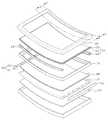
도 1은 본 발명의 일실시예에 따른 표시 장치의 분해 사시도이다.
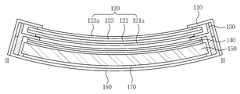
도 2는 도 1의 Ⅰ-Ⅰ을 따라 절단한 단면도이다.
도 3은 도 1의 Ⅱ-Ⅱ를 따라 절단한 단면도이다.
도 4는 본 발명의 일실시예에 따른 표시 패널을 나타낸 사시도이다.
도 5 내지 도 7은 본 발명의 다른 일실시예에 따른 표시 패널을 나타낸 사시도이다.
도 8a 및 도 8b는 기존 표시 패널과 본 발명의 일실시예에 따른 표시 패널에 가해지는 응력을 나타낸 도이다.1 is an exploded perspective view of a display device according to an embodiment of the present invention.
2 is a cross-sectional view taken along the line I-I in Fig.
3 is a cross-sectional view taken along line II-II in FIG.
4 is a perspective view illustrating a display panel according to an embodiment of the present invention.
5 to 7 are perspective views illustrating a display panel according to another embodiment of the present invention.
8A and 8B are diagrams showing stress applied to a display panel according to an exemplary embodiment of the present invention and an existing display panel.
이하, 첨부도면을 참조하여 본 발명을 상세히 설명한다.Hereinafter, the present invention will be described in detail with reference to the accompanying drawings.
본 발명은 다양한 변경이 가능하고, 여러 가지 형태로 실시될 수 있는 바, 특정의 실시예만을 도면에 예시하고 본문에는 이를 중심으로 설명한다. 그렇다고 하여 본 발명의 범위가 상기 특정한 실시예로 한정되는 것은 아니며, 본 발명의 사상 및 기술 범위에 포함되는 모든 변경, 균등물 또는 대체물은 본 발명의 범위에 포함되는 것으로 이해되어야 한다.While the present invention has been described in connection with certain embodiments, it is obvious to those skilled in the art that various changes and modifications may be made therein without departing from the spirit and scope of the invention as defined by the appended claims. It is to be understood, however, that the scope of the present invention is not limited to the specific embodiments described above, and all changes, equivalents, or alternatives included in the spirit and technical scope of the present invention are included in the scope of the present invention.
본 명세서에서 어떤 부분이 다른 부분과 연결되어 있다고 할 때, 이는 직접적으로 연결되어 있는 경우뿐 아니라, 그 중간에 다른 소자를 사이에 두고 전기적으로 연결되어 있는 경우도 포함한다. 또한, 어떤 부분이 어떤 구성 요소를 포함한다고 할 때, 이는 특별히 반대되는 기재가 없는 한 다른 구성요소를 제외하는 것이 아니라 다른 구성요소를 더 포함할 수 있는 것을 의미한다.In this specification, when a part is connected to another part, it includes not only a direct connection but also a case where the part is electrically connected with another part in between. In addition, when a part includes an element, it does not exclude other elements unless specifically stated otherwise, but may include other elements.
본 명세서에서 제1, 제2, 제3 등의 용어는 다양한 구성 요소들을 설명하는데 사용될 수 있지만, 이러한 구성 요소들은 상기 용어들에 의해 한정되는 것은 아니다. 상기 용어들은 하나의 구성 요소를 다른 구성 요소들로부터 구별하는 목적으로 사용된다. 예를 들어, 본 발명의 권리 범위로부터 벗어나지 않고, 제1 구성 요소가 제2 또는 제3 구성 요소 등으로 명명될 수 있으며, 유사하게 제2 또는 제3 구성 요소도 교호적으로 명명될 수 있다.The terms first, second, third, etc. in this specification may be used to describe various components, but such components are not limited by these terms. The terms are used for the purpose of distinguishing one element from another. For example, without departing from the scope of the present invention, the first component may be referred to as a second or third component, and similarly, the second or third component may be alternately named.
본 발명을 명확하게 설명하기 위해서 설명과 관계없는 부분은 생략하였으며, 명세서 전체를 통하여 동일 또는 유사한 구성요소에 대해서는 동일한 참조 부호를 붙인다.In order to clearly illustrate the present invention, parts not related to the description are omitted, and the same or similar components are denoted by the same reference numerals throughout the specification.
본 명세서에서 표시 장치는 가로 길이가 세로 길이보다 길고, 가로 방향으로 만곡된 랜드스케이프(landscape) 타입인 것을 전제로 설명하지만 이에 한정되는 것이 아님은 물론이다.In this specification, the display device is assumed to be a landscape type in which the horizontal length is longer than the vertical length and is curved in the horizontal direction, but the present invention is not limited thereto.
본 명세서에서 표시 장치는 액정 표시 패널인 것을 전제로 설명하지만 이에 한정되는 것은 아니며, 표시 패널은 OLED(Organic Light Emitting Diode) 패널일 수도 있다.In this specification, the display device is assumed to be a liquid crystal display panel, but the present invention is not limited thereto, and the display panel may be an OLED (Organic Light Emitting Diode) panel.
또한, 본 명세서에서 표시 장치는 에지형(edge type) 백라이트 유닛을 포함하는 것을 전제로 설명하지만 이에 한정되는 것은 아니며, 직하형(direct type) 백라이트 유닛 또는 코너형(corner type) 백라이트 유닛일 수도 있다.In this specification, the display device is assumed to include an edge type backlight unit, but the present invention is not limited thereto, and it may be a direct type backlight unit or a corner type backlight unit .
도 1은 본 발명의 일실시예에 따른 표시 장치의 분해 사시도이다. 도 2는 도 1의 Ⅰ-Ⅰ를 따라 절단한 단면도이고, 도 3은 도 1의 Ⅱ-Ⅱ를 따라 절단한 단면도이다. 본 발명의 일실시예에 따른 표시 장치(100)는 에지형 백라이트 유닛을 갖는 랜드스케이프 타입의 표시 장치이다.1 is an exploded perspective view of a display device according to an embodiment of the present invention. FIG. 2 is a sectional view taken along the line I-I in FIG. 1, and FIG. 3 is a sectional view taken along line II-II in FIG. A display device 100 according to an embodiment of the present invention is a land-view type display device having an edge type backlight unit.
도 1 내지 도 3을 참조하면, 본 발명의 일실시예에 따른 표시 장치(100)는 상부 프레임(또는 탑 샤시라 함)(110), 표시 패널(120), 중간 프레임(또는 몰드 프레임이라 함)(130), 광학 시트(140), 도광판(150), 광원부(160), 반사 시트(170), 및 하부 프레임(또는 바텀 샤시라 함)(180)을 포함한다. 이하에서, 중간 프레임(130), 광학 시트(140), 도광판(150), 광원부(160), 반사 시트(170), 및 하부 프레임(180) 등을 통칭하여 백라이트 유닛이라 한다. 위 열거된 구성 요소는 곡면 형상에 맞춰 오목하게 만곡된 형태를 갖는다.1 to 3, a display device 100 according to an embodiment of the present invention includes an upper frame 110 (referred to as a top chassis), a
상부 프레임(110), 중간 프레임(130), 및 하부 프레임(180)과 같은 고정 프레임은 일정한 곡률(curvature)을 갖도록 제작될 수 있다. 표시 패널(120)은 고정 프레임과 결합되기 전에 만곡된 형태를 가질 수 있고, 고정 프레임과 결합됨으로써 만곡된 형태를 가질 수도 있다.Fixed frames such as the
즉, 표시 패널(120)이 플렉서블 타입(flexible type)이라면 고정 프레임에 결합됨으로써 만곡된 형태를 가질 수 있으며, 표시 패널(120)이 리지드 타입(rigid type)이라면 고정 프레임에 삽입되기 이전에 일정한 곡률을 가질 수 있다. 일반적으로 표시 패널(120)은 편평한 형태로 제작된 후, 고정 프레임과의 결합에 의해 일정한 곡률을 가질 수 있다. 고정 프레임은 1000mm 내지 5000mm의 곡률 반경(Radius of curvature)을 가질 수 있다.That is, if the
상부 프레임(110)은 표시 패널(120)의 표시 영역(Active area)이 외부로 노출될 수 있도록 개방창을 가지며, 표시 패널(120)의 상면 가장자리 및 측면을 덮도록(cover) 배치될 수 있다.The
상부 프레임(110)은 표시 패널(120)의 상면 가장자리를 고정하여, 표시 패널(120)이 백라이트 유닛으로부터 이탈되는 것을 방지할 수 있으며, 중간 프레임(130) 및 하부 프레임(180)에 고정될 수 있다. 상부 프레임(110)은 후크 결합 및/또는 나사 결합을 통하여 중간 프레임(130) 및 하부 프레임(180)에 고정될 수 있다.The
상부 프레임(110)은 스테인리스 스틸과 같은 강성을 가지는 금속 재질 또는 알루미늄 혹은 알루미늄 합금과 같이 방열 특성이 좋은 재질로 형성될 수 있다. 상부 프레임(110)은 소정은 곡률을 갖도록 금형 프레스 공정 등으로 형성될 수 있다.The
표시 패널(120)은 광을 이용하여 영상을 표시하는 사각의 판상으로, 적어도 일방향으로 휘어질 수 있는 플렉서블 패널이다. 표시 패널(120)의 상대적으로 길이가 긴 두 개의 변(이하, 장변)은 일정한 곡률로 오목하게 만곡된 형태를 가지며, 상대적으로 길이가 짧은 두 개의 변(이하, 단변)은 직선 형태를 갖는다. 다른 실시예에 따른 표시 패널(120)은 단변이 일정한 곡률로 오목하게 만곡된 형태를 갖고, 장변이 직선 형태를 가질 수도 있다.The
표시 패널(120)은 제 1 기판(121), 제 1 기판(121)에 대향되는 제 2 기판(123), 및 제 1 기판(121)과 제 2 기판(123) 사이에 배치된 액정층(미도시)을 포함한다. 이때, 제 1 기판(121)은 제 2 기판(123)보다 더 큰 곡률 반경을 가질 수 있다.The
표시 패널(120)의 만곡 방향을 따라 제 1 기판(121)의 배면 가장자리에 적어도 하나 이상의 탄성 부재(125)가 배치될 수 있다. 특히, 탄성 부재(125)는 제 1 기판(121)의 만곡 방향을 따라 제 1 기판(121)의 배면 가장자리에 배치될 수 있다.At least one
도 1은 탄성 부재(125)가 표시 패널(120)의 측면을 덮도록 연장된 것으로 도시되어 있으나 반드시 이에 한정되는 것은 아니며, 탄성 부재(125)는 제 1 기판(121) 배면 가장자리에만 배치될 수 있으며, 탄성 부재(125)는 표시 패널(120)의 전면 가장자리까지 덮도록 연장되어 배치될 수도 있다.1 illustrates the
탄성 부재(125)가 배면 가장자리에 배치됨으로써, 제 1 기판(121) 배면에 가해지는 인장 응력을 완화시킬 수 있다. 탄성 부재(125)가 표시 패널(120)의 측면 및 전면 가장자리까지 연장되어 배치됨으로써, 제 1 기판(121) 배면에 가해지는 인장 응력을 완화시키고, 표시 패널(120)의 기구 강도를 향상시킬 수 있다. 탄성 부재(125)의 보다 자세한 구성에 대해서는 후술한다.The
제 1 기판(121)은 매트릭스 형태로 배치된 복수의 화소 전극, 화소 전극 각각에 구동 전압을 인가하는 박막 트랜지스터, 및 화소 전극과 박막 트랜지스터를 구동하기 위한 각종 신호선을 포함한다.The
제 2 기판(123)은 제 1 기판(121)과 대향되도록 배치되며, 투명 전도성 물질로 형성된 공통 전극, 및 컬러 필터를 포함한다. 컬러 필터는 적색, 녹색, 및 청색 컬러 필터가 있다.The
액정층(미도시)은 제 1 기판(121) 및 제 2 기판(123) 사이에 개재되며, 화소 전극 및 공통 전극 사이에 형성된 전기장에 의하여 재배열된다. 이와 같이, 재배열된 액정층은 백라이트 유닛으로부터 출사된 광의 투과율을 조절하고, 이렇게 조절된 광이 컬러 필터를 통과 함으로써 영상을 외부로 표시한다.A liquid crystal layer (not shown) is interposed between the
또한, 제 1 기판(121)의 배면에 하부 편광판(121a) 및 제 2 기판(123)의 상면에 상부 편광판(123a)이 각각 더 배치될 수 있다. 상부 편광판(123a) 및 하부 편광판(121a)은 표시 패널(120)에 대응되는 면적을 가질 수 있다. 상부 편광판(123a)은 외부에서 도달하는 광 중 특정 편광만 통과시키며, 나머지는 흡수 또는 차단시킬 수 있다. 하부 편광판(121a)은 백라이트 유닛에서 출력되는 광 중에서 특정 편광만 통과시키거나, 나머지는 흡수 또는 차단시킬 수 있다.Further, the
표시 패널(120)의 적어도 일변에 표시 패널(120)을 구동하기 위한 구동 회로 기판(미도시)이 배치될 수 있다. 구동 회로 기판은 표시 패널(120)을 구동시키기 위한 각종 제어 신호 및 전원 신호를 제공할 수 있다.A driving circuit board (not shown) for driving the
중간 프레임(130)은 사각의 고리 형상을 갖는다. 중간 프레임(130)은 표시 패널(120)을 지지하며, 광학 시트(140), 및 도광판(150) 등을 수용한다. 중간 프레임(130)은 단일 형태로 이루어질 수 있으나, 필요에 따라 복수개로 형성된 후 조립될 수도 있다.The
중간 프레임(130)은 표시 패널(120)의 파손을 방지하기 위해 플라스틱과 같이 유연한 재질로 형성될 수 있다. 중간 프레임(130)은 소정의 곡률을 갖도록 사출 성형 공정 등으로 형성될 수 있다.The
광학 시트(140)는 도광판(150) 상에 배치되어 도광판(150)으로부터 전달되는 빛을 확산 또는 집광하는 역할을 한다. 광학 시트(140)는 확산 시트, 프리즘 시트, 및 보호 시트를 포함한다. 확산 시트, 프리즘 시트, 및 보호 시트는 그 열거된 순서로 도광판(150) 상에 차례로 적층된다.The
프리즘 시트는 도광판(150)에 의해 안내된 광을 집광하고, 확산 시트는 프리즘 시트에 의해 집광된 광을 확산 시키며, 그리고 보호 시트는 프리즘 시트를 보호하는 역할을 한다. 보호 시트를 통과한 광은 표시 패널(120) 측으로 제공된다.The prism sheet condenses the light guided by the
도광판(150)은 광원부(160)로부터 제공받은 광을 표시 패널(120)로 균일하게 공급한다. 도광판(150)은 편평한 형태로 제작된 후, 고정 프레임과의 결합에 의해 소정의 곡률을 가질 수 있다. 도광판(150)은 소정의 곡률을 갖도록 휘어질 수 있는 재질로 형성된다.The
도광판(150)은 4각형의 판상으로 형성될 수 있으나 이에 한정되는 것은 아니며, LED 칩과 같은 광원을 사용하는 경우, 광원의 위치에 따라 소정의 홈 또는 돌기 등을 포함하는 다양한 형상으로 형성될 수 있다.The
도광판(150)은 설명의 편의상, 플레이트(plate)로 기술하였으나, 표시 장치의 슬림화를 위해 시트 또는 필름 형태로 형성될 수 있다. 즉, 도광판(150)은 광을 가이드하기 위한 플레이트 및 필름을 모두 포함할 수 있다.Although the
도광판(150)은 광을 효율적으로 가이드할 수 있도록 투광성을 가지는 재료, 예를 들어 PMMA(PolyMethylMethAcrylate)와 같은 아크릴 수지, 폴리카보네이트(PolyCarbonate)와 같은 재료를 포함하여 형성될 수 있다.The
도광판(150)과 하부 프레임(180) 사이에 반사 시트(170)가 배치된다. 반사 시트(170)는 도광판(150)의 하부로 방출되는 빛을 표시 패널(120)로 향하도록 반사시켜 빛의 효율을 향상시킨다.A
광원부(160)는 광원(161) 및 광원(161)이 배치된 회로기판(163)을 포함한다.The
광원(161)은 도광판(150)의 모서리부 또는 입광 측면에 배치될 수 있다. 즉, 광원(161)은 도광판(150)의 모서리부 또는 입광 측면으로 광을 출사할 수 있다. 광원(161)은 적어도 하나의 LED 칩(미도시)과 LED 칩을 수용하는 패키지(미도시)를 포함할 수 있다. 예를 들어, LED 칩(미도시)은 청색광을 방출하는 질화갈륨(GaN)계 LED 칩일 수 있다.The
광원(161)의 개수는 표시 패널(120)의 크기, 및 휘도 균일성 등을 고려하여 다양한 값을 가질 수 있다. 회로 기판(163)은 인쇄 회로 기판(Printed Circuit Board, PCB) 또는 금속 인쇄 회로 기판(metal PCB)일 수 있다.The number of the
도 1에는 도시되지 않았지만, 도광판(150)과 광원부(160) 사이에는 파장 변환부(미도시)가 배치될 수 있다. 파장 변환부(미도시)는 광의 파장을 변환시키는 물질을 포함할 수 있다. 예를 들어, 파장 변환부는 청색 LED 광원에서 나오는 청색광의 파장을 변환시켜 백색광으로 변환시킬 수 있다.Although not shown in FIG. 1, a wavelength conversion unit (not shown) may be disposed between the
또한, 도 1에는 도시되지 않았지만, 광원부(160)과 하부 프레임(180) 사이에 방열 부재(미도시)가 배치될 수 있다. 방열 부재는 광원부(160)에서 발생한 열을 외부로 방출한다. 광원부(160)가 하부 프레임(180)의 일 측면에 바(bar) 또는 라인(line) 형태로 배치된 경우, 방열 부재도 바(bar) 또는 라인(line) 형태를 갖는 금속 프레임으로 배치될 수 있다. 이와 같이, 방열 부재는 광원부(160)의 형태에 따라서 다양한 형태를 가질 수 있다.Although not shown in FIG. 1, a radiation member (not shown) may be disposed between the
반사 시트(170)는, 예를 들어 폴리에틸렌 테레프탈레이트(PET: PolyEthylene Terephthalate)로 이루어져 반사성을 가질 수 있으며, 그 한쪽 표면은 예를 들어, 티타늄 디옥사이드를 함유하는 확산층으로 코팅될 수 있다. 또한, 반사 시트(170)는 은(Ag)과 같은 금속을 포함하는 재질로 형성될 수도 있다.The
하부 프레임(180)은 표시 장치의 골격을 유지하며, 내부에 수납되는 각종 구성 요소를 보호한다. 하부 프레임(180)은 스테인리스 스틸과 같은 강성을 가지는 금속 재질 또는 알루미늄 혹은 알루미늄 합금과 같이 방열 특성이 좋은 재질로 이루어질 수 있다. 하부 프레임(180)은 소정의 곡률을 갖도록 금형 프레스 공정 등으로 형성될 수 있다.The
도 4는 본 발명의 일실시예에 따른 표시 패널을 나타낸 사시도이다.4 is a perspective view illustrating a display panel according to an embodiment of the present invention.
도 4를 참조하면, 본 발명의 일실시예에 따른 표시 패널(120)은 서로 마주하는 제 1 기판(121)과 제 2 기판(123), 제 1 기판(121)과 제 2 기판(123) 사이에 배치된 액정층(미도시), 제 1 기판(121) 배면에 배치된 하부 편광판(121a), 제 2 기판(123) 상면에 배치된 상부 편광판(미도시), 및 표시 패널(120)의 만곡 방향을 따라 제 1 기판(121) 배면 가장자리에 배치된 탄성 부재(125)를 포함할 수 있다.4, a
이 때, 제 1 기판(121)은 제 2 기판(123)보다 더 큰 곡률 반경을 가질 수 있다. 즉, 표시 패널(120)은 제 1 기판(121)에 인장 응력이 발생하고, 제 2 기판(123)에 압축 응력에 발생하도록 오목하게 만곡될 수 있다.In this case, the
탄성 부재(125)는 인장 응력이 발생하는 제 1 기판(121) 배면 가장자리에 표시 패널(120)의 곡률 방향을 따라 배치될 수 있다. 탄성 부재(125)는 표시 패널(120)의 장변부를 기준으로 상단 및 하단에 배치될 수 있다. 또한, 본 발명의 일실시예에 따른 탄성 부재(125)는 제 1 기판(121)의 배면 가장자리 및 표시 패널(120)의 측면을 덮도록 절곡되어 배치될 수 있다.The
탄성 부재(125)는 탄성 계수가 높은 고탄성 금속 또는 고분자 물질로 형성될 수 있다.The
예를 들어, 고탄성 금속은 알루미늄(Al), 구리(Cu), 형상 기억 합금, 니티놀(Nitinol), 몰리브덴(Mo), 텅스텐(W), 스프링 스테인리스강, 엘길로이(Elgiloy), 하스탈로이 (hastalloy), 베타 티타늄(β-titanum), 및 이들의 합금 중 적어도 하나를 포함할 수 있다. 이외에도, 탄성 계수가 높은 고탄성 금속이라면 본 발명에 제한 없이 사용될 수 있다.For example, the high-elasticity metal may be aluminum (Al), copper (Cu), shape memory alloy, Nitinol, molybdenum (Mo), tungsten (W), spring stainless steel, Elgiloy, hastalloy, beta-titanum, and alloys thereof. In addition, a high-elasticity metal having a high elastic modulus can be used without limitation in the present invention.
예를 들어, 고분자 물질은 시아노아크릴레이트 수지(cyanoacrylate resin), 에폭시수지(epoxy resin), 폴리올레핀(polyolefine), 폴리메틸메타아크릴레이트(poly(methyl methacrylate): PMMA), 폴리아크릴레이트(polyacrylate), 폴리아크릴산(polyacrylic acid), 폴리 우레탄(polyurethane), 폴리에틸렌테레프탈레이트(polyethylene terephthalate, PET) 등의 폴리에스테르계, 실리콘 수지 중 적어도 하나를 포함할 수 있다. 이외에도, 탄성 계수가 높은 고분자 물질이라면 본 발명에 제한 없이 사용될 수 있다.For example, the polymer material may be selected from the group consisting of cyanoacrylate resin, epoxy resin, polyolefin, polymethyl methacrylate (PMMA), polyacrylate, Based resin such as polyethylene terephthalate (PET), polyacrylic acid, polyurethane, and silicone resin. In addition, the polymeric material having a high elastic modulus can be used without limitation in the present invention.
탄성 부재(125)는 고탄성 금속 또는 고분자 물질을 프레스 가공하거나, 압출 성형 또는 사출 성형 등의 다양한 공정을 이용하여 제작할 수 있다.The
탄성 부재(125)는 접착 부재(미도시) 또는 점착 부재(미도시)에 의해 제 1 기판(121) 배면에 접착 또는 점착될 수 있다. 접착 부재는 열경화성 접착제 또는 자외선(UV) 경화성 접착제일 수 있다. 자외선 경화성 접착제의 경우는 통상적으로 자외선에 의해 경화 가능한 단량체들과 광 개시제, 광증진제및 필요에 따라서 용제를 포함할 수 있으며, 글루(glue)액체로 이루어질 수도 있다.The
접착 부재 또는 점착 부재는 액상이나 점성이 있는 상태에서 도포된 후, 일정 시간 또는 일정 온도 하에서 경화될 수 있다. 따라서, 별도의 기구물 없이 접착 부재 또는 점착 부재를 이용하여 제 1 기판(121)과 탄성 부재(125)를 견고하게 고정시킬 수 있다.The adhesive member or the adhesive member may be applied in a liquid or viscous state and then cured at a constant temperature or at a constant temperature. Therefore, the
도 5 내지 도 7은 본 발명의 다른 일실시예에 따른 표시 패널을 나타낸 사시도이다. 본 발명의 다른 일실시예에 따른 표시 패널에 대한 설명 중 본 발명의 일실시예에 따른 표시 패널에 대한 설명과 중복되는 내용은 생략한다.5 to 7 are perspective views illustrating a display panel according to another embodiment of the present invention. The description of the display panel according to another embodiment of the present invention and the description of the display panel according to the embodiment of the present invention will be omitted.
도 5 내지 도 7을 참조하면, 본 발명의 다른 일실시예에 따른 표시 패널(120)은 서로 마주하는 제 1 기판(121)과 제 2 기판(123), 제 1 기판(121)과 제 2 기판(123) 사이에 배치된 액정층(미도시), 제 1 기판(121) 배면에 배치된 하부 편광판(121a), 제 2 기판(123) 상면에 배치된 상부 편광판(미도시), 및 표시 패널(120)의 만곡 방향을 따라 제 1 기판(121) 배면 가장자리에 배치된 탄성 부재(125)를 포함할 수 있다.5 to 7, a
탄성 부재(125)는 제 1 기판(121) 배면 가장자리에만 배치(도 5 참조)되거나, 제 1 기판(121) 배면 가장자리에 복수개로 분할되어 배치(도 6 참조)될 수 있다. 또한, 탄성 부재(125)는 표시 패널(120)의 측면 및 전면 가장자리까지 연장되어 배치(도 7 참조)될 수 있다.The
도 8a 및 도 8b는 기존 표시 패널과 본 발명의 일실시예에 따른 표시 패널에 가해지는 응력을 나타낸 도이다.8A and 8B are diagrams showing stress applied to a display panel according to an exemplary embodiment of the present invention and an existing display panel.
표시 장치는 곡면 형태를 구현하기 위해서 곡면(curved) 고정 프레임에 평면(flat) 표시 패널을 결합함으로써 구현될 수 있다. 이 때, 곡면 고정 프레임의 곡률 형태에 따라 편평한 표시 패널에 일정한 외력이 가해지게 되는데, 이로 인해 표시 패널 상판과 하판에 각각 다른 형태의 응력이 발생한다.The display device can be implemented by combining a flat display panel with a curved fixed frame to realize a curved shape. At this time, depending on the curvature shape of the curved surface fixing frame, a constant external force is applied to the flat display panel, so that different types of stress are generated on the upper and lower display panels.
도 8a를 참조하면, 기존 표시 패널(20)의 경우 중립면(Neutral Plane, 中立面)(NP)을 기준으로, 제 1 기판(21)은 곡률 반경에서 외측으로 볼록하게 만곡되면서 인장 응력(Tensile Stress, TS)을 받고, 제 2 기판(23)은 곡률 반경에서 내측으로 오목하게 만곡되면서 압축 응력(Compressive Stress, CS)을 받게 된다. 중립면(NP)은 어떠한 물질이 힘을 받아 휘어질 때, 늘어나거나 줄어들지 않고 본래의 길이를 유지하는 면을 말한다.Referring to FIG. 8A, in the case of the
제 1 기판(21), 및 제 2 기판(23)은 일반적으로 유리 기판이 사용될 수 있는데, 유리 기판의 특성상 압축 응력에 대한 저항은 비교적 큰 반면 인장응력에 대한 저항은 매우 낮다. 따라서, 외력이 가해지는 경우, 인장 응력이 발생하는 제 1 기판 깨질 수 있다.The
도 8b를 참조하면, 본 발명에 따른 표시 패널(120)의 경우 인장 응력이 발생 하는 제 1 기판(121) 배면에 탄성 부재(125)가 배치된다. 표시 패널(120)이 만곡됨에 따라 탄성 부재(125)에 원래 상태로 돌아가려는 탄성력(Elastic Force, EF)이 발생한다. 이러한 탄성력(EF)에 의해 제 1 기판(121)에 발생하는 인장 응력(TS)이 완화될 수 있다.Referring to FIG. 8B, in the case of the
또한, 제 1 기판(121)에 발생하는 인장 응력으로 인해, 제 1 기판(121) 가장자리에 크랙(crack)이 발생한다 하더라도, 탄성 부재(125)와 제 1 기판(121) 사이의 접착 부재 또는 점착 부재에 의해 크랙의 추가적인 진행을 억제할 수 있다.Even if a crack is generated at the edge of the
이상, 첨부된 도면을 참조하여 본 발명의 일실시예들을 설명하였지만, 본 발명이 속하는 기술분야에서 통상의 지식을 가진 자는 본 발명의 그 기술적 사상이나 필수적인 특징을 변경하지 않고서 다른 구체적인 형태로 실시될 수 있다는 것을 이해할 수 있을 것이다. 그러므로 이상에서 기술한 일실시예들은 모든 면에서 예시적인 것이며 한정적이 아닌 것으로 이해해야만 한다. While the present invention has been described in connection with what is presently considered to be practical exemplary embodiments, it is to be understood that the invention is not limited to the disclosed embodiments, but, on the contrary, You can understand that you can. It is therefore to be understood that the embodiments described above are illustrative in all aspects and not restrictive.
110: 상부 프레임120: 표시 패널
130: 중간 프레임140: 광학 시트
150: 도광판160: 광원부
170: 반사 시트180: 하부 프레임110: upper frame 120: display panel
130: intermediate frame 140: optical sheet
150: light guide plate 160:
170: reflective sheet 180: lower frame
Claims (8)
Translated fromKorean상기 표시 패널의 만곡 방향을 따라 상기 제 1 기판의 배면 가장자리에 배치된 적어도 하나 이상의 탄성 부재; 및
일정한 곡률을 가지며, 상기 표시 패널을 지지 및 고정하기 위한 고정 프레임;을 포함하며,
상기 제 1 기판은 상기 제 2 기판보다 더 큰 곡률 반경을 갖는 표시 장치.A display panel including a first substrate and a second substrate facing each other and curved in one direction;
At least one elastic member disposed at a rear edge of the first substrate along a curved direction of the display panel; And
A fixed frame having a predetermined curvature and for supporting and fixing the display panel,
Wherein the first substrate has a larger radius of curvature than the second substrate.
8. The display device according to claim 7, wherein the adhesive member comprises at least one of a thermosetting adhesive and a UV-curable adhesive.
Priority Applications (2)
| Application Number | Priority Date | Filing Date | Title |
|---|---|---|---|
| KR1020140128256AKR20160036715A (en) | 2014-09-25 | 2014-09-25 | Display device |
| US14/659,768US10108036B2 (en) | 2014-09-25 | 2015-03-17 | Display device including curved display panel |
Applications Claiming Priority (1)
| Application Number | Priority Date | Filing Date | Title |
|---|---|---|---|
| KR1020140128256AKR20160036715A (en) | 2014-09-25 | 2014-09-25 | Display device |
Publications (1)
| Publication Number | Publication Date |
|---|---|
| KR20160036715Atrue KR20160036715A (en) | 2016-04-05 |
Family
ID=55586035
Family Applications (1)
| Application Number | Title | Priority Date | Filing Date |
|---|---|---|---|
| KR1020140128256AAbandonedKR20160036715A (en) | 2014-09-25 | 2014-09-25 | Display device |
Country Status (2)
| Country | Link |
|---|---|
| US (1) | US10108036B2 (en) |
| KR (1) | KR20160036715A (en) |
Cited By (3)
| Publication number | Priority date | Publication date | Assignee | Title |
|---|---|---|---|---|
| CN105866996A (en)* | 2016-05-25 | 2016-08-17 | 合肥惠科金扬科技有限公司 | Curved display apparatus |
| WO2018117586A1 (en)* | 2016-12-19 | 2018-06-28 | 황창순 | Flexible display device and method for transforming display device |
| WO2019190045A1 (en)* | 2018-03-29 | 2019-10-03 | (주)코텍 | Liquid crystal panel etching method |
Families Citing this family (13)
| Publication number | Priority date | Publication date | Assignee | Title |
|---|---|---|---|---|
| TWM496780U (en)* | 2014-09-15 | 2015-03-01 | Innolux Corp | Electronic display device |
| CN104633548A (en)* | 2015-02-05 | 2015-05-20 | 深圳市华星光电技术有限公司 | Backlight module and curved surface liquid crystal display device |
| CN104597650B (en)* | 2015-02-16 | 2017-09-05 | 深圳市华星光电技术有限公司 | The front frame and curved surface liquid crystal display device of curved surface liquid crystal display device |
| US9817261B2 (en)* | 2015-04-28 | 2017-11-14 | Lg Display Co., Ltd. | Curved cover for curved display and curved type display apparatus including the same |
| CN105259607B (en)* | 2015-10-12 | 2018-11-23 | 京东方科技集团股份有限公司 | Curved surface back light unit, display device and manufacturing method |
| CN105629575A (en)* | 2016-03-24 | 2016-06-01 | 京东方科技集团股份有限公司 | Curved-surface backlight source and display device |
| CN109074186B (en)* | 2016-04-08 | 2022-12-06 | 希迪普公司 | Pressure sensor, touch input device including same and pressure detection method using same |
| CN109154426A (en)* | 2016-05-20 | 2019-01-04 | 富士胶片株式会社 | Light guide member and back light unit and liquid crystal display device |
| JP6945529B2 (en)* | 2016-06-22 | 2021-10-06 | 富士フイルム株式会社 | Light guide member and liquid crystal display |
| CN110248618B (en) | 2016-09-09 | 2024-01-09 | 莫比乌斯成像公司 | Method and system for displaying patient data in computer-assisted surgery |
| JP6907036B2 (en) | 2017-06-12 | 2021-07-21 | 株式会社ジャパンディスプレイ | Display device |
| CN107909927B (en)* | 2017-12-14 | 2024-02-13 | 京东方科技集团股份有限公司 | Flexible display panel and preparation method thereof |
| CN217214038U (en)* | 2022-01-18 | 2022-08-16 | 群创光电股份有限公司 | Electronic device |
Family Cites Families (10)
| Publication number | Priority date | Publication date | Assignee | Title |
|---|---|---|---|---|
| JP2000206556A (en) | 1999-01-12 | 2000-07-28 | Matsushita Electric Ind Co Ltd | Liquid crystal display |
| JP2001265251A (en)* | 2000-03-17 | 2001-09-28 | Minolta Co Ltd | Display element and multilayer display element |
| US20050122464A1 (en)* | 2003-12-03 | 2005-06-09 | International Business Machines Corporation | One-drop fill spacerless process for liquid crystal cell on a silicon backplane or microdisplays |
| JP2007272107A (en) | 2006-03-31 | 2007-10-18 | Sharp Corp | Display device |
| KR20090115523A (en) | 2008-05-02 | 2009-11-05 | 엘지이노텍 주식회사 | Display |
| WO2011155117A1 (en)* | 2010-06-09 | 2011-12-15 | シャープ株式会社 | Display device |
| KR101300020B1 (en)* | 2011-09-05 | 2013-08-29 | 주식회사 토비스 | Method for manufacturing display panel with curved shape |
| KR101300021B1 (en) | 2011-09-05 | 2013-08-29 | 주식회사 토비스 | Method for manufacturing display panel with curved shape |
| KR102041883B1 (en) | 2012-07-09 | 2019-11-08 | 삼성디스플레이 주식회사 | Curved frame and curved display device having the same |
| KR101426997B1 (en) | 2012-07-31 | 2014-08-05 | 이피네트시스템즈 주식회사 | Method for manufacturing display panel with curved shape and display panel with curved shape using the method |
- 2014
- 2014-09-25KRKR1020140128256Apatent/KR20160036715A/ennot_activeAbandoned
- 2015
- 2015-03-17USUS14/659,768patent/US10108036B2/enactiveActive
Cited By (3)
| Publication number | Priority date | Publication date | Assignee | Title |
|---|---|---|---|---|
| CN105866996A (en)* | 2016-05-25 | 2016-08-17 | 合肥惠科金扬科技有限公司 | Curved display apparatus |
| WO2018117586A1 (en)* | 2016-12-19 | 2018-06-28 | 황창순 | Flexible display device and method for transforming display device |
| WO2019190045A1 (en)* | 2018-03-29 | 2019-10-03 | (주)코텍 | Liquid crystal panel etching method |
Also Published As
| Publication number | Publication date |
|---|---|
| US10108036B2 (en) | 2018-10-23 |
| US20160095205A1 (en) | 2016-03-31 |
Similar Documents
| Publication | Publication Date | Title |
|---|---|---|
| KR20160036715A (en) | Display device | |
| KR102301094B1 (en) | Display device | |
| JP5933509B2 (en) | Liquid crystal display | |
| US9182539B2 (en) | Liquid crystal display device and method of manufacturing the same | |
| KR20160035132A (en) | Display device | |
| KR102311058B1 (en) | Display device | |
| KR102365173B1 (en) | Backlight unit and display device including the same | |
| US10228579B2 (en) | Display device and multi display device using the same | |
| US20160334560A1 (en) | Display device including accommodating member | |
| KR102538876B1 (en) | Display device | |
| KR20160035133A (en) | Display device | |
| KR101900057B1 (en) | Liquid crystal display device | |
| KR102525224B1 (en) | Display apparatus | |
| KR20160147110A (en) | Display device | |
| KR20160015476A (en) | Display device | |
| US20160109648A1 (en) | Display device | |
| US20160178956A1 (en) | Display device | |
| US20150022756A1 (en) | Backlight module and corresponding liquid crystal display device | |
| KR102187828B1 (en) | Display device | |
| KR101868866B1 (en) | Liquid crystal display device | |
| KR20180099956A (en) | Liquid crystal display device | |
| KR20150038876A (en) | Liquid crystal display apparatus | |
| KR102132767B1 (en) | Liquid crystal display device | |
| US20160320542A1 (en) | Backlight unit with heat dissipating member and liquid crystal display device including the same | |
| KR101333267B1 (en) | Liquid crystal display device |
Legal Events
| Date | Code | Title | Description |
|---|---|---|---|
| PA0109 | Patent application | Patent event code:PA01091R01D Comment text:Patent Application Patent event date:20140925 | |
| PG1501 | Laying open of application | ||
| A201 | Request for examination | ||
| PA0201 | Request for examination | Patent event code:PA02012R01D Patent event date:20190918 Comment text:Request for Examination of Application Patent event code:PA02011R01I Patent event date:20140925 Comment text:Patent Application | |
| E902 | Notification of reason for refusal | ||
| PE0902 | Notice of grounds for rejection | Comment text:Notification of reason for refusal Patent event date:20200729 Patent event code:PE09021S01D | |
| E701 | Decision to grant or registration of patent right | ||
| PE0701 | Decision of registration | Patent event code:PE07011S01D Comment text:Decision to Grant Registration Patent event date:20201224 | |
| PC1904 | Unpaid initial registration fee |