KR20160024992A - Space filling devices - Google Patents
Space filling devicesDownload PDFInfo
- Publication number
- KR20160024992A KR20160024992AKR1020167002200AKR20167002200AKR20160024992AKR 20160024992 AKR20160024992 AKR 20160024992AKR 1020167002200 AKR1020167002200 AKR 1020167002200AKR 20167002200 AKR20167002200 AKR 20167002200AKR 20160024992 AKR20160024992 AKR 20160024992A
- Authority
- KR
- South Korea
- Prior art keywords
- hub member
- frame
- elongate
- hub
- section
- Prior art date
- Legal status (The legal status is an assumption and is not a legal conclusion. Google has not performed a legal analysis and makes no representation as to the accuracy of the status listed.)
- Granted
Links
Images


Classifications
- A—HUMAN NECESSITIES
- A61—MEDICAL OR VETERINARY SCIENCE; HYGIENE
- A61B—DIAGNOSIS; SURGERY; IDENTIFICATION
- A61B17/00—Surgical instruments, devices or methods
- A61B17/12—Surgical instruments, devices or methods for ligaturing or otherwise compressing tubular parts of the body, e.g. blood vessels or umbilical cord
- A61B17/12022—Occluding by internal devices, e.g. balloons or releasable wires
- A61B17/12099—Occluding by internal devices, e.g. balloons or releasable wires characterised by the location of the occluder
- A61B17/12122—Occluding by internal devices, e.g. balloons or releasable wires characterised by the location of the occluder within the heart
- A—HUMAN NECESSITIES
- A61—MEDICAL OR VETERINARY SCIENCE; HYGIENE
- A61B—DIAGNOSIS; SURGERY; IDENTIFICATION
- A61B17/00—Surgical instruments, devices or methods
- A61B17/12—Surgical instruments, devices or methods for ligaturing or otherwise compressing tubular parts of the body, e.g. blood vessels or umbilical cord
- A61B17/12022—Occluding by internal devices, e.g. balloons or releasable wires
- A61B17/12131—Occluding by internal devices, e.g. balloons or releasable wires characterised by the type of occluding device
- A61B17/12168—Occluding by internal devices, e.g. balloons or releasable wires characterised by the type of occluding device having a mesh structure
- A61B17/12172—Occluding by internal devices, e.g. balloons or releasable wires characterised by the type of occluding device having a mesh structure having a pre-set deployed three-dimensional shape
- A—HUMAN NECESSITIES
- A61—MEDICAL OR VETERINARY SCIENCE; HYGIENE
- A61B—DIAGNOSIS; SURGERY; IDENTIFICATION
- A61B17/00—Surgical instruments, devices or methods
- A61B17/12—Surgical instruments, devices or methods for ligaturing or otherwise compressing tubular parts of the body, e.g. blood vessels or umbilical cord
- A61B17/12022—Occluding by internal devices, e.g. balloons or releasable wires
- A61B17/12131—Occluding by internal devices, e.g. balloons or releasable wires characterised by the type of occluding device
- A61B17/12168—Occluding by internal devices, e.g. balloons or releasable wires characterised by the type of occluding device having a mesh structure
- A61B17/12177—Occluding by internal devices, e.g. balloons or releasable wires characterised by the type of occluding device having a mesh structure comprising additional materials, e.g. thrombogenic, having filaments, having fibers or being coated
- A—HUMAN NECESSITIES
- A61—MEDICAL OR VETERINARY SCIENCE; HYGIENE
- A61F—FILTERS IMPLANTABLE INTO BLOOD VESSELS; PROSTHESES; DEVICES PROVIDING PATENCY TO, OR PREVENTING COLLAPSING OF, TUBULAR STRUCTURES OF THE BODY, e.g. STENTS; ORTHOPAEDIC, NURSING OR CONTRACEPTIVE DEVICES; FOMENTATION; TREATMENT OR PROTECTION OF EYES OR EARS; BANDAGES, DRESSINGS OR ABSORBENT PADS; FIRST-AID KITS
- A61F2/00—Filters implantable into blood vessels; Prostheses, i.e. artificial substitutes or replacements for parts of the body; Appliances for connecting them with the body; Devices providing patency to, or preventing collapsing of, tubular structures of the body, e.g. stents
- A61F2/01—Filters implantable into blood vessels
- A—HUMAN NECESSITIES
- A61—MEDICAL OR VETERINARY SCIENCE; HYGIENE
- A61B—DIAGNOSIS; SURGERY; IDENTIFICATION
- A61B17/00—Surgical instruments, devices or methods
- A61B17/12—Surgical instruments, devices or methods for ligaturing or otherwise compressing tubular parts of the body, e.g. blood vessels or umbilical cord
- A61B17/12022—Occluding by internal devices, e.g. balloons or releasable wires
- A61B17/12099—Occluding by internal devices, e.g. balloons or releasable wires characterised by the location of the occluder
- A61B17/12109—Occluding by internal devices, e.g. balloons or releasable wires characterised by the location of the occluder in a blood vessel
- A—HUMAN NECESSITIES
- A61—MEDICAL OR VETERINARY SCIENCE; HYGIENE
- A61B—DIAGNOSIS; SURGERY; IDENTIFICATION
- A61B17/00—Surgical instruments, devices or methods
- A61B2017/00004—(bio)absorbable, (bio)resorbable or resorptive
- A—HUMAN NECESSITIES
- A61—MEDICAL OR VETERINARY SCIENCE; HYGIENE
- A61B—DIAGNOSIS; SURGERY; IDENTIFICATION
- A61B17/00—Surgical instruments, devices or methods
- A61B2017/00526—Methods of manufacturing
- A—HUMAN NECESSITIES
- A61—MEDICAL OR VETERINARY SCIENCE; HYGIENE
- A61B—DIAGNOSIS; SURGERY; IDENTIFICATION
- A61B17/00—Surgical instruments, devices or methods
- A61B17/0057—Implements for plugging an opening in the wall of a hollow or tubular organ, e.g. for sealing a vessel puncture or closing a cardiac septal defect
- A61B2017/00575—Implements for plugging an opening in the wall of a hollow or tubular organ, e.g. for sealing a vessel puncture or closing a cardiac septal defect for closure at remote site, e.g. closing atrial septum defects
- A61B2017/00579—Barbed implements
- A—HUMAN NECESSITIES
- A61—MEDICAL OR VETERINARY SCIENCE; HYGIENE
- A61B—DIAGNOSIS; SURGERY; IDENTIFICATION
- A61B17/00—Surgical instruments, devices or methods
- A61B17/0057—Implements for plugging an opening in the wall of a hollow or tubular organ, e.g. for sealing a vessel puncture or closing a cardiac septal defect
- A61B2017/00575—Implements for plugging an opening in the wall of a hollow or tubular organ, e.g. for sealing a vessel puncture or closing a cardiac septal defect for closure at remote site, e.g. closing atrial septum defects
- A61B2017/00592—Elastic or resilient implements
- A—HUMAN NECESSITIES
- A61—MEDICAL OR VETERINARY SCIENCE; HYGIENE
- A61B—DIAGNOSIS; SURGERY; IDENTIFICATION
- A61B17/00—Surgical instruments, devices or methods
- A61B17/0057—Implements for plugging an opening in the wall of a hollow or tubular organ, e.g. for sealing a vessel puncture or closing a cardiac septal defect
- A61B2017/00575—Implements for plugging an opening in the wall of a hollow or tubular organ, e.g. for sealing a vessel puncture or closing a cardiac septal defect for closure at remote site, e.g. closing atrial septum defects
- A61B2017/00597—Implements comprising a membrane
- A—HUMAN NECESSITIES
- A61—MEDICAL OR VETERINARY SCIENCE; HYGIENE
- A61B—DIAGNOSIS; SURGERY; IDENTIFICATION
- A61B17/00—Surgical instruments, devices or methods
- A61B17/0057—Implements for plugging an opening in the wall of a hollow or tubular organ, e.g. for sealing a vessel puncture or closing a cardiac septal defect
- A61B2017/00575—Implements for plugging an opening in the wall of a hollow or tubular organ, e.g. for sealing a vessel puncture or closing a cardiac septal defect for closure at remote site, e.g. closing atrial septum defects
- A61B2017/00615—Implements with an occluder on one side of the opening and holding means therefor on the other
- A—HUMAN NECESSITIES
- A61—MEDICAL OR VETERINARY SCIENCE; HYGIENE
- A61B—DIAGNOSIS; SURGERY; IDENTIFICATION
- A61B17/00—Surgical instruments, devices or methods
- A61B17/0057—Implements for plugging an opening in the wall of a hollow or tubular organ, e.g. for sealing a vessel puncture or closing a cardiac septal defect
- A61B2017/00575—Implements for plugging an opening in the wall of a hollow or tubular organ, e.g. for sealing a vessel puncture or closing a cardiac septal defect for closure at remote site, e.g. closing atrial septum defects
- A61B2017/00632—Occluding a cavity, i.e. closing a blind opening
- A—HUMAN NECESSITIES
- A61—MEDICAL OR VETERINARY SCIENCE; HYGIENE
- A61B—DIAGNOSIS; SURGERY; IDENTIFICATION
- A61B17/00—Surgical instruments, devices or methods
- A61B2017/00831—Material properties
- A61B2017/00867—Material properties shape memory effect
- A—HUMAN NECESSITIES
- A61—MEDICAL OR VETERINARY SCIENCE; HYGIENE
- A61B—DIAGNOSIS; SURGERY; IDENTIFICATION
- A61B17/00—Surgical instruments, devices or methods
- A61B2017/00982—General structural features
- A61B2017/00986—Malecots, e.g. slotted tubes, of which the distal end is pulled to deflect side struts
Landscapes
- Health & Medical Sciences (AREA)
- Life Sciences & Earth Sciences (AREA)
- Surgery (AREA)
- General Health & Medical Sciences (AREA)
- Animal Behavior & Ethology (AREA)
- Vascular Medicine (AREA)
- Engineering & Computer Science (AREA)
- Biomedical Technology (AREA)
- Heart & Thoracic Surgery (AREA)
- Veterinary Medicine (AREA)
- Public Health (AREA)
- Medical Informatics (AREA)
- Reproductive Health (AREA)
- Molecular Biology (AREA)
- Nuclear Medicine, Radiotherapy & Molecular Imaging (AREA)
- Cardiology (AREA)
- Oral & Maxillofacial Surgery (AREA)
- Transplantation (AREA)
- Surgical Instruments (AREA)
- Prostheses (AREA)
- Filling Of Jars Or Cans And Processes For Cleaning And Sealing Jars (AREA)
- Specific Sealing Or Ventilating Devices For Doors And Windows (AREA)
- Tents Or Canopies (AREA)
- Toys (AREA)
Abstract
Translated fromKoreanDescription
Translated fromKorean본 개시는, 환자 내부의 개구, 도관(conduit), 또는 구조물을 폐색(occlude)하기 위해서 이용될 수 있는 이식 가능한(implantable) 의료 장치에 관한 것이다.The present disclosure relates to an implantable medical device that can be used to occlude an opening, a conduit, or a structure within a patient.
심방이(atrial appendage)와 같은 심장 부분(cardiac feature)들은, 많은 수의 심장-관련 병리학(pathology)과 연관되는, 심장 혈액 유동 장애에 기여할 수 있다. 예를 들어, 좌심방이(LAA) 내의 혈액 유동 장애에 의해서 유발되고 심방세동(atrial fibrillation)는 합병증(complication)이 색전성 뇌졸중(embolic stroke)에 기여할 수 있다. LAA는 심장의 좌심방의 전측 벽(anterolateral wall)으로부터 연장하는 근낭(muscular pouch)이고 좌심방을 위한 저장부로서의 역할을 한다. 정상적인 심장 사이클 중에, LAA가 좌심방과 함께 수축하여 LAA로부터 혈액을 펌핑하고, 이는 일반적으로 혈액이 LAA 내에서 정체하는 것을 방지한다. 그러나, 부정맥(arrhythmias)(예를 들어, 심방세동)을 특징으로 하는 심장 사이클 중에, LAA가 종종 충분히 수축하는데 실패하고, 이는 혈액이 LAA 내에서 정체하게 할 수 있다. LAA 내의 정체된 혈액이 응고(coagulating) 및 혈전(thrombus)에 대해서 민감할 수 있고, 이는 LAA로부터 제거될 수 있고 최종적으로 색전성 뇌졸중을 초래할 수 있다.Cardiac features, such as atrial appendage, can contribute to cardiac blood flow disorders associated with a large number of cardiac-related pathologies. For example, atrial fibrillation may be caused by blood flow disorder in the left atrium (LAA) and complication may contribute to embolic stroke. LAA is a muscular pouch extending from the anterolateral wall of the left atrium of the heart and serves as a reservoir for the left atrium. During a normal cardiac cycle, LAA contracts with the left atrium and pumps blood from the LAA, which generally prevents blood from stagnating in the LAA. However, during a cardiac cycle characterized by arrhythmias (e. G., Atrial fibrillation), LAA often fails to fully contract, which can cause blood to stagnate within the LAA. Stagnant blood in the LAA can be sensitive to coagulating and thrombus, which can be removed from the LAA and ultimately lead to a stunning stroke.
제1 전반적 양태에서, 의료 장치가 복수의 세장형 프레임 부재를 포함하는 장치 프레임을 포함하며, 각각의 세장형 프레임 부재가 제1 단부 및 제2 단부를 포함한다. 의료 장치가, 복수의 세장형 부재의 제1 단부를 집속하는(aggregating) 제1 허브 부재, 및 복수의 세장형 부재의 제2 단부를 집속하는 제2 허브 부재를 또한 포함한다. 의료 장치는 제1 허브 부재를 제2 허브 부재에 커플링시키는 커플링 요소를 더 포함하고, 제1 허브 부재 및 제2 허브 부재가 장치 프레임의 길이방향 축선을 따라서 실질적으로 정렬된다. 장치 프레임은 면 섹션(face section), 측방향을 향한 스커트 섹션, 및 반전된 섹션을 포함하고, 세장형 부재의 제1 부분이 면 섹션을 형성하고 제1 허브 부재로부터 반경방향으로 연장하며, 세장형 부재의 제2 부분이 측방향을 향한 스커트 섹션을 형성하고 원위(distal)의 축방향을 향해 나선 방향으로 면 섹션으로부터 제1 회전 방향을 따라서 연장하고, 세장형 부재의 제3 부분이 반전된 섹션을 형성하고 대체로 측방향을 향한 스커트 섹션의 원위 부분으로부터 근위 방향으로 제2 허브 부재까지 제1 회전 방향에 반대되는 회전 방향을 따라서 연장한다.In a first general aspect, a medical device includes a device frame including a plurality of elongate frame members, each elongate frame member including a first end and a second end. The medical device also includes a first hub member for aggregating the first end of the plurality of elongate members and a second hub member for concentrating the second end of the plurality of elongate members. The medical device further includes a coupling element coupling the first hub member to the second hub member such that the first hub member and the second hub member are substantially aligned along the longitudinal axis of the apparatus frame. The apparatus frame includes a face section, a skirt section toward the side, and an inverted section, wherein a first portion of the elongate member forms a surface section and extends radially from the first hub member, Wherein the second portion of the elongate member defines a laterally directed skirt section and extends from the surface section along the first rotational direction in a spiral direction toward a distal axial direction and wherein the third portion of the elongate member is inverted Section and extends along the direction of rotation from the distal portion of the generally laterally directed skirt section to the second hub member in a proximal direction, opposite the first rotational direction.
여러 가지 구현예가 이하 중 하나 이상을 포함할 수 있을 것이다. 커플링 요소는 접착제, 용접부, 리벳, 또는 기계적 구성요소일 수 있을 것이다. 각각의 세장형 프레임 부재에 대해서, 제1 허브 부재로부터의 출구 위치와 제2 허브 부재로의 입구 위치 사이에 형성된 각도가 약 140° 내지 약 360°의 범위, 또는 약 225° 내지 약 315°의 범위, 또는 약 255° 내지 약 285°의 범위, 또는 약 270°일 수 있을 것이다. 의료 장치는 또한, 장치 프레임에 부착된 적어도 하나의 앵커 구성요소를 포함할 수 있다. 세장형 프레임 부재의 각각이 하나 이상의 와이어를 포함할 수 있을 것이다. 세장형 프레임 부재는 관의 부분들을 포함할 수 있을 것이다. 제1 회전 방향은 시계방향, 또는 반시계방향일 수 있을 것이다. 장치 프레임의 면 섹션은 실질적으로 편평할 수 있거나, 대체로 볼록한 형상 또는 대체로 오목한 형상을 가질 수 있을 것이다. 제1 허브 부재이 아일릿(eyelet)일 수 있을 것이고, 제2 허브 부재가 아일릿일 수 있을 것이다. 제1 허브 부재가 링 부재일 수 있고, 제2 허브 부재는 아일릿일 수 있을 것이다. 제1 허브 부재가 링 부재일 수 있고, 제2 허브 부재가 링 부재일 수 있을 것이다. 제2 허브 부재가 제1 허브 부재 내에 동심으로 배치될 수 있을 것이다. 의료 장치는 또한, 면 섹션에 그리고 측방향을 향한 스커트 섹션에 부착된 커버링 구성요소를 포함할 수 있을 것이다. 커버링 구성요소가 반전된 섹션에 부착되지 않을 수 있을 것이다. 커버링 구성요소는 그러한 커버링 구성요소를 통한 혈액의 통과를 방지하도록 구성될 수 있을 것이다. 커버링 구성요소는 혈액은 커버링 구성요소를 통과할 수 있게 하면서도 혈전은 커버링 구성요소를 통과하지 않게 함으로써, 필터링하도록 구성될 수 있을 것이다. 반전된 섹션의 제1 부분이 측방향을 향한 스커트 섹션의 적어도 일부에 대향할 수 있을 것이고, 반전된 섹션의 제2 부분은 적어도 면 섹션의 일부에 대향할 수 있을 것이다. 의료 장치는 또한 면 섹션, 측방향을 향한 스커트 섹션, 및 반전된 섹션의 제2 부분에 부착된 커버링 구성요소를 포함할 수 있을 것이고, 그러한 커버링 구성요소는 반전된 섹션의 제1 부분에 부착되지 않을 수 있을 것이다.Various implementations may include one or more of the following. The coupling element may be an adhesive, a weld, a rivet, or a mechanical component. For each elongate frame member, an angle formed between the outlet position from the first hub member and the inlet position to the second hub member is in the range of about 140 degrees to about 360 degrees, or in the range of about 225 degrees to about 315 degrees Range, or in the range of about 255 ° to about 285 °, or about 270 °. The medical device may also include at least one anchor component attached to the device frame. Each of the elongate frame members may comprise one or more wires. The elongate frame member may comprise portions of the tube. The first rotation direction may be clockwise or counterclockwise. The face sections of the device frame may be substantially flat, or may have a generally convex shape or a generally concave shape. The first hub member may be an eyelet, and the second hub member may be an eyelet. The first hub member may be a ring member and the second hub member may be an eyelet. The first hub member may be a ring member, and the second hub member may be a ring member. The second hub member may be concentrically disposed within the first hub member. The medical device may also include a covering component attached to the skirt section and to the side section. The covering component may not be attached to the inverted section. The covering component may be configured to prevent the passage of blood through such a covering component. The covering component may be configured to filter blood by allowing the blood to pass through the covering component but not through the covering component. The first portion of the inverted section may be opposed to at least a portion of the laterally directed skirt section and the second portion of the inverted section may be opposed to at least a portion of the face section. The medical device may also include a face section, a skirt section toward the side, and a covering component attached to the second section of the inverted section, such a covering component being attached to the first section of the inverted section I will not.
제2의 일반적인 양태에서, 의료 장치가, 복수의 세장형 프레임 부재를 포함하는 장치 프레임을 포함하고, 세장형 프레임 부재의 각각이 제1 단부 및 제2 단부를 포함한다. 의료 장치가 또한 복수의 세장형 부재의 제1 단부를 집속하는 제1 허브 부재, 및 복수의 세장형 부재의 제2 단부를 집속하는 제2 허브 부재를 포함한다. 의료 장치가 또한, 제1 허브 부재를 제2 허브 부재에 커플링시키는 커플링 요소를 포함하고, 제1 허브 부재 및 제2 허브 부재가 장치 프레임의 길이방향 축선을 따라서 실질적으로 정렬된다. 장치 프레임이 면 섹션, 측방향을 향한 스커트 섹션, 및 반전된 섹션을 포함한다. 세장형 부재의 제1 부분이 면 섹션을 형성하고 제1 허브 부재로부터 반경방향으로 연장하며, 세장형 부재의 제2 부분이 측방향을 향한 스커트 섹션을 형성하고 원위의 축방향을 향해 나선 방향으로 면 섹션으로부터 제1 회전 방향을 따라서 연장하고, 세장형 부재의 제3 부분이 반전된 섹션을 형성하고 대체로 근위 방향으로 측방향을 향한 스커트 섹션의 원위 부분으로부터 제2 허브 부재까지 제1 회전 방향에 반대되는 회전 방향을 따라서 연장한다. 의료 장치가 면 섹션에 그리고 측방향을 향한 스커트 섹션에 부착된 커버링 구성요소를 더 포함한다.In a second general aspect, the medical device comprises a device frame comprising a plurality of elongate frame members, each of the elongate frame members including a first end and a second end. The medical device also includes a first hub member to which the first ends of the plurality of elongate members are guided, and a second hub member that guides the second ends of the plurality of elongate members. The medical device also includes a coupling element coupling the first hub member to the second hub member such that the first hub member and the second hub member are substantially aligned along the longitudinal axis of the apparatus frame. The device frame includes a face section, a skirt section toward the side, and an inverted section. Wherein the first portion of the elongate member forms a face section and extends radially from the first hub member and the second portion of the elongate member forms a laterally directed skirt section and extends in a spiral direction towards a distal axial direction Extending from the side section along the first rotational direction and wherein the third portion of the elongate member forms an inverted section and extends from the distal portion of the generally proximally laterally facing skirt section to the second hub member in the first rotational direction And extends along the opposite rotational direction. The medical device further includes a covering component attached to the side section and to the side facing skirt section.
여러 가지 구현예가 이하 중 하나 이상을 포함할 수 있다. 커버링 구성요소는 반전된 섹션에 부착되지 않을 수 있을 것이다. 커버링 구성요소는 그러한 커버링 구성요소를 통한 혈액의 통과를 방지하도록 구성될 수 있을 것이다. 커버링 구성요소는 혈액은 커버링 구성요소를 통과할 수 있게 하면서도 혈전은 커버링 구성요소를 통과하지 않게 함으로써, 필터링하도록 구성될 수 있을 것이다. 반전된 섹션의 제1 부분이 측방향을 향한 스커트 섹션의 적어도 일부에 대향할 수 있을 것이고, 반전된 섹션의 제2 부분은 적어도 면 섹션의 일부에 대향할 수 있을 것이다. 커버링 구성요소가 반전된 섹션의 제2 부분에 부착될 수 있을 것이고 반전된 섹션의 제1 부분에 부착되지 않을 수 있을 것이다.Various implementations may include one or more of the following. The covering component may not be attached to the inverted section. The covering component may be configured to prevent the passage of blood through such a covering component. The covering component may be configured to filter blood by allowing the blood to pass through the covering component but not through the covering component. The first portion of the inverted section may be opposed to at least a portion of the laterally directed skirt section and the second portion of the inverted section may be opposed to at least a portion of the face section. The covering element may be attached to the second portion of the inverted section and not attached to the first portion of the inverted section.
하나 이상의 실시예의 상세 내용이 첨부 도면 및 이하의 설명에서 개진된다. 다른 특징, 목적 및 장점이 상세한 설명 및 도면, 그리고 청구항으로부터 명확해질 것이다.The details of one or more embodiments are set forth in the accompanying drawings and the description below. Other features, objects, and advantages will be apparent from the description and drawings, and from the claims.
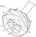
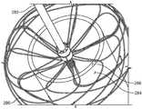
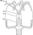
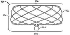
도 1a, 도 1b, 도 1c는 환자의 신체 내의 홀, 결함, 개구, 부속기(appendage), 혈관(vessel) 또는 도관을 폐색하기 위해서 이용될 수 있는 예시적인 폐색 장치의 사시도이다.
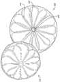
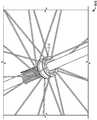
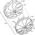
도 2는 다른 예시적인 폐색 장치의 정면도 및 또 다른 예시적인 폐색 장치의 사시도이다.
도 3a는 예시적인 지그(jig) 장비의 사시도이다.
도 3b는 예시적인 지그 장비의 상면도로서, 장치 프레임을 권선(wind)하기 위해서 이용될 수 있는 권선 패턴을 도시한다.
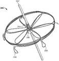
도 4는 예시적인 장치 프레임의 사시도이다.
도 5a는, 후크 형상을 가지는 예시적인 앵커를 포함하는 예시적인 장치 프레임의 사시도이다.
도 5b는 예시적인 폐색 장치의 정면도이다.
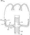
도 6은, 본 명세서에서 설명된 장치 프레임의 컵 형상의 특징부(cupped feature)를 제공할 수 있는 예시적인 제조 공정을 도시한다.
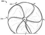
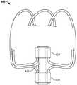
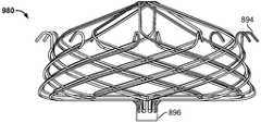
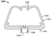
도 7은, 장치의 컵 형상의 특징부를 도시하는 예시적인 폐색 장치의 원위 부분의 사시도이다.
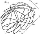
도 8은 맨드릴(mandrel)를 따라서 세장화되고, 커버링 구성요소가 부착될 프레임의 부분으로 접착제가 도포된, 예시적인 장치 프레임의 사시도이다.
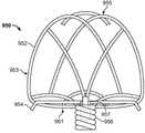
도 9는 예시적인 장치 프레임의 사시도이다.
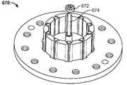
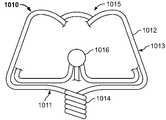
도 10은 예시적인 장치 프레임의 일부, 및 예시적인 링 부재의 사시도이다.
도 11은 예시적인 장치 프레임의 일부의 개념도이다.
도 12는 다른 예시적인 장치 프레임의 일부의 개념도이다.
도 13은 또 다른 예시적인 장치 프레임의 일부의 개념도이다.
도 14는 또 다른 예시적인 장치 프레임의 일부의 개념도이다.
도 15는 또 다른 예시적인 장치 프레임의 일부의 개념도이다.
도 16은 또 다른 예시적인 장치 프레임의 일부의 개념도이다.
도 17은 또 다른 예시적인 장치 프레임의 일부의 개념도이다.
도 18a, 도 18b, 및 도 18c는, 재료의 관으로 형성된 세장형 부재를 가지는 장치 프레임을 포함하는 예시적인 장치의 사시도이다.
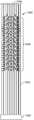
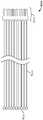
도 19는 NiTi 관으로부터 레이저-컷팅된 이후의, 세장형의, 미리-열-셋팅된(pre-heat-set) 구성의 예시적인 장치 프레임의 도면이다.
도 20 내지 도 25는 예시적인 장치 프레임의 부분의 개념도이다.
도 26a는, 본 명세서에서 제공된 폐색 장치의 실시예에 포함되는 예시적인 앵커 구성요소의 사시도이다.
도 26b는 예시적인 폐색 장치의 세장형 부재에 부착된 도 26a의 앵커 구성요소를 도시한 사시도이다.
도 26c는 커버링 구성요소를 포함하는 예시적인 폐색 장치에 장착된 도 26a의 앵커 구성요소를 도시한 사시도이다.
도 27a 내지 도 27d는, 본 명세서에서 제공된 실시예에 따라서 허브 부재들 또는 아일릿들을 서로의 내부에 포개는 것(nesting)을 예시한 도면이다.
도 28a 내지 도 28c는 본 명세서에서 제공된 실시예에 따라서 포개진 아일릿을 가지는 폐색 장치를 구성하기 위한 기술을 도시한다.
도 29a 및 도 29b는 포개진 아일릿을 가지는 폐색 장치를 형성하기 위해서 이용될 수 있는 권선 지그의 사시도 및 측면도이다.
도 30a 및 도 30b는 원위 앵커링 조립체를 가지는 예시적인 폐색 장치 실시예를 도시한다.
도 31a 및 도 31b는 원위 앵커링 조립체를 가지는 예시적인 폐색 장치 실시예를 도시한다.
도 32는 예시적인 폐색 장치 실시예의 측면 사시도이다.
도 33a 내지 도 33d는 예시적인 폐색 장치 실시예의 여러 가지 도면을 도시한다.
도 34a는 다른 예시적인 폐색 장치 실시예의 사시도를 도시한다.
도 34b는 도 34a의 폐색 장치와 함께 이용될 수 있는 원위 앵커링 부재를 도시한다.
도 34c 및 도 34d는 도 34a의 폐색 장치의 부가적인 도면이다.
도 35는 예시적인 폐색 장치 프레임 실시예의 측면도이다.
도 36은 도 35의 예시적인 폐색 장치 프레임의 사시도이다.
도 37은 예시적인 앵커 프레임 실시예의 측면도이다.
도 38은 다른 예시적인 앵커 프레임 실시예의 측면도이다.
도 39는 도 38의 예시적인 앵커 프레임의 사시도이다.
도 40은 다른 예시적인 폐색 장치 프레임 실시예의 측면도이다.
도 41은 도 40의 예시적인 폐색 장치 프레임의 사시도이다.
도 42는 다른 예시적인 폐색 장치 프레임 실시예의 측면도이다.
도 43은 또 다른 예시적인 폐색 장치 프레임의 일부의 개념도이다.
도 44는 또 다른 예시적인 폐색 장치 프레임의 일부의 개념도이다.
도 45는 또 다른 예시적인 폐색 장치 프레임의 일부의 개념도이다.
도 46은 또 다른 예시적인 폐색 장치 프레임의 일부의 개념도이다.
도 47은 다른 예시적인 폐색 장치 프레임 실시예의 측면도이다.
도 48은 도 47의 예시적인 폐색 장치 프레임의 사시도이다.
도 49는 다른 예시적인 폐색 장치 프레임 실시예의 측면도이다.
도 50은 도 49의 예시적인 폐색 장치 프레임의 분해도이다.
도 51은 다른 예시적인 폐색 장치 프레임 실시예의 측면도이다.
도 52는 도 51의 예시적인 폐색 장치 프레임의 분해도이다.
도 53은 또 다른 예시적인 폐색 장치 프레임의 일부의 개념도이다.
도 54는 또 다른 예시적인 폐색 장치 프레임의 일부의 개념도이다.
도 55는 또 다른 예시적인 폐색 장치 프레임의 일부의 개념도이다.
도 56은 일부 실시예에 따른 폐색 장치 프레임을 위한 재료 컷팅 패턴을 도시한다.
도 57은 일부 실시예에 따른 폐색 장치 프레임을 위한 다른 재료 컷팅 패턴을 도시한다.
도 58은 일부 실시예에 따른 폐색 장치 프레임을 위한 다른 재료 컷팅 패턴을 도시한다.
도 59는 또 다른 예시적인 폐색 장치 프레임의 일부의 개념도이다.
도 60은 또 다른 예시적인 폐색 장치 프레임의 일부의 개념도이다.
도 61은 일부 실시예에 따른 폐색 장치 프레임을 위한 다른 재료 컷팅 패턴을 도시한다.
도 62는 일부 실시예에 따른 폐색 장치 프레임을 위한 다른 재료 컷팅 패턴을 도시한다.
도 63a는 또 다른 예시적인 폐색 장치 프레임의 일부의 개념도이다.
도 63b 및 도 63c는 도 63a 의 폐색 장치 프레임의 허브 부재 부분을 도시한다.
여러 도면 내의 유사한 참조 부호들이 유사한 요소들을 나타낸다.Figures 1a, 1b, 1c are perspective views of exemplary occlusion devices that may be used to occlude holes, defects, openings, appendages, vessels, or conduits within a patient's body.
2 is a front view of another exemplary occluding device and a perspective view of another exemplary occluding device.
Figure 3a is a perspective view of an exemplary jig rig.
Figure 3B is a top view of an exemplary jig equipment showing a winding pattern that can be used to wind the apparatus frame.
4 is a perspective view of an exemplary device frame.
5A is a perspective view of an exemplary apparatus frame including an exemplary anchor having a hook shape.
Figure 5B is a front view of an exemplary occlusion device.
Figure 6 illustrates an exemplary fabrication process capable of providing cupped features of the device frame described herein.
7 is a perspective view of a distal portion of an exemplary occlusion device showing cup-shaped features of the device.
Figure 8 is a perspective view of an exemplary device frame that is elongated along a mandrel and to which an adhesive is applied as part of the frame to which the covering component is to be attached.
9 is a perspective view of an exemplary device frame.
10 is a perspective view of a portion of an exemplary apparatus frame and an exemplary ring member.
11 is a conceptual diagram of a portion of an exemplary device frame.
12 is a conceptual diagram of a portion of another exemplary device frame.
13 is a conceptual diagram of a portion of another exemplary device frame.
14 is a conceptual diagram of a portion of another exemplary device frame.
15 is a conceptual diagram of a portion of another exemplary device frame.
16 is a conceptual diagram of a portion of another exemplary device frame.
17 is a conceptual diagram of a portion of another exemplary device frame.
18A, 18B, and 18C are perspective views of an exemplary apparatus including an apparatus frame having elongate members formed from a tube of material.
FIG. 19 is a drawing of an exemplary device frame in a pre-heat-set configuration, which is elongated, after laser-cutting from a NiTi tube.
20 to 25 are conceptual diagrams of a portion of an exemplary device frame.
26A is a perspective view of an exemplary anchor component included in an embodiment of the occluding device provided herein.
26B is a perspective view showing the anchor component of Fig. 26A attached to the elongated member of an exemplary occlusion device.
26C is a perspective view showing the anchor component of FIG. 26A mounted to an exemplary occlusion device including a covering component.
27A-27D are diagrams illustrating nesting hub members or eyelets within each other in accordance with an embodiment provided herein.
28A-28C illustrate techniques for constructing an occluding device having a collapsed eyelet according to an embodiment provided herein.
29A and 29B are a perspective view and a side view of a winding jig that can be used to form an occluding device having a collapsed eyelet.
30A and 30B illustrate an exemplary occlusion device embodiment having a distal anchoring assembly.
Figures 31A and 31B illustrate an exemplary occlusion device embodiment having a distal anchoring assembly.
32 is a side perspective view of an exemplary occlusion device embodiment;
33A-33D illustrate various views of an exemplary occlusion device embodiment.
34A shows a perspective view of another exemplary occlusion device embodiment.
34B shows a distal anchoring member that can be used with the occlusion device of Fig. 34A. Fig.
34C and 34D are additional views of the occlusion device of FIG. 34A.
35 is a side view of an exemplary occluder frame embodiment.
36 is a perspective view of the exemplary occluder device frame of Fig. 35;
37 is a side view of an exemplary anchor frame embodiment.
38 is a side view of another exemplary anchor frame embodiment.
39 is a perspective view of the exemplary anchor frame of Fig.
40 is a side view of another exemplary occluder frame embodiment.
41 is a perspective view of the exemplary occluder device frame of Fig.
42 is a side view of another exemplary occluder frame embodiment;
43 is a conceptual diagram of a portion of another exemplary occluding device frame.
44 is a conceptual diagram of a portion of another exemplary occluding device frame.
45 is a conceptual diagram of a portion of another exemplary occluding device frame.
46 is a conceptual diagram of a portion of another exemplary occluding device frame.
47 is a side view of another exemplary occluding device frame embodiment.
Figure 48 is a perspective view of the exemplary occluder device frame of Figure 47;
49 is a side view of another exemplary occluder frame embodiment.
50 is an exploded view of the exemplary occluder device frame of FIG. 49;
51 is a side view of another exemplary occluder frame embodiment;
Figure 52 is an exploded view of the exemplary occluder device frame of Figure 51;
53 is a conceptual diagram of a portion of another exemplary occluding device frame.
54 is a conceptual diagram of a portion of another exemplary occluding device frame.
55 is a conceptual diagram of a portion of another exemplary occluding device frame.
56 illustrates a material cutting pattern for an occlusion device frame in accordance with some embodiments.
Figure 57 illustrates another material cutting pattern for an occlusion device frame in accordance with some embodiments.
58 shows another material cutting pattern for an occlusion device frame according to some embodiments.
59 is a conceptual diagram of a portion of another exemplary occluding device frame.
60 is a conceptual diagram of a portion of another exemplary occluding device frame.
61 shows another material cutting pattern for an occlusion device frame according to some embodiments.
62 illustrates another material cutting pattern for an occlusion device frame in accordance with some embodiments.
63A is a conceptual diagram of a portion of another exemplary occluding device frame.
Figs. 63B and 63C show the hub member portion of the occluding device frame of Fig. 63A. Fig.
Like numbers refer to like elements throughout the several views.
본 문헌은, 예를 들어, 환자의 신체 내의 공간, 홀, 결함, 개구, 부속기, 혈관 또는 도관을 완전히, 부분적으로, 또는 실질적으로 폐색하는데 있어서 유용한 장치, 시스템 및 방법을 설명한다. 부가적인 용도가, 일부 구현예에서, 필터링을 포함할 수 있다. 몇 가지 이식 가능한 의료 장치가 본 명세서에서 설명되고, 일반적으로 특별한 장치에 대해서 설명된 임의의 특징이 또한 본 명세서에서 설명된 다른 임의의 장치와 함께 이용될 수 있을 것이다. 일부 예에서, 특별한 장치에 대해서 설명된 하나 이상의 특징부가 다른 장치의 하나 이상의 특징에 대해서 대체 또는 치환될 수 있을 것이다. 일부 예에서, 특별한 장치에 대해서 설명된 하나 이상의 특징부가 다른 장치에 부가되거나 포함될 수 있을 것이다. 또한, 본 명세서에서 설명된 임의 특징부의 여러 가지 조합 또는 하위-조합이 본 명세서에서 설명된 임의 장치와 함께 일반적으로 이용될 수 있을 것이다.This document describes devices, systems, and methods that are useful, for example, to completely, partially, or substantially occlude spaces, holes, defects, openings, appendages, blood vessels, or conduits within a patient's body. Additional uses may, in some implementations, include filtering. Several implantable medical devices are described herein and any feature described generally in connection with a particular device may also be used with any of the other devices described herein. In some instances, one or more of the described features for a particular device may be substituted or substituted for one or more features of the other device. In some instances, one or more features described with respect to a particular device may be added or included in another device. In addition, various combinations or sub-combinations of any features described herein may generally be utilized with any of the devices described herein.
일반적으로, 본 명세서에서 설명된 임의의 이식 가능한 의료 장치가, 여러 가지 최소 침습형 트랜스카테너 전개 기술(minimally invasive transcatheter deployment technique)을 이용하여, 환자의 신체 내의 체내(in vivo) 전개 사이트(site)로 전달될 수 있고 그리고 전개 사이트에서 전개될 수 있다. 예를 들어, 본 명세서에서 설명된 임의의 이식 가능한 의료 장치가 전달 카테터로 해제 가능하게 부착될 수 있을 것이고, 그러한 장치 및 전달 카테터가 전달 외장(sheath) 내로 적재될(loaded) 수 있을 것이다. 전달 외장이 환자의 맥관 구조(vasculature)로 도입되고, 전달 외장의 원위 단부가 체내 전개 사이트 내의 표적에 또는 그 근처에 위치될 때까지, 맥관 구조를 통해서 전진될 수 있을 것이다. 이식 가능한 의료 장치가, 예를 들어, 전달 카테터를 이용하여 전달 외장의 원위 단부 외부로 장치를 밀어내고 장치를 전달 카테터로부터 탈착시키는 것에 의해서, 전개 사이트에서 전개될 수 있을 것이다. 일부 예에서, 전달 카테터의 위치 및 이식 가능한 의료 장치를 유지(또는 전진)하면서 전달 외장을 후퇴시키는 것 그리고 장치를 전달 카테터로부터 탈착시키는 것에 의해서, 장치가 전개될 수 있다. 일부 구현예에서, 장치의 제2 부분이 전달 외장에 의해서 구속되어 유지되는 동안 장치의 제1 부분이 전달 외장으로부터 해제되고, 장치의 제1 부분의 배치가 확인되고, 이어서 장치의 제2 부분이 전달 외장으로부터 해제된다. 이어서, 전달 카테터 및 전달 외장이 환자의 신체로부터 회수(withdrawn) 또는 후퇴될 수 있다. 일부 예에서, 테터(tether), 봉합사, 또는 케이블과 같은 회수(retrieval) 요소가 장치의 부분으로 해제 가능하게 부착된다. 필요한 경우에, 회수 요소가 전개 이후에 장치를 회수 또는 재포획(recapture)하기 위해서 이용될 수 있다.In general, any implantable medical device described herein may be deployed in an in-vivo deployment site within a patient's body, using a variety of minimally invasive transcatheter deployment techniques. ) And can be deployed at the deployment site. For example, any implantable medical device described herein may be releasably attached to a delivery catheter, such device and delivery catheter being loaded into a delivery sheath. The delivery sheath may be introduced through the vasculature until it is introduced into the vasculature of the patient and the distal end of the delivery sheath is located at or near the target in the body deployment site. An implantable medical device may be deployed at the deployment site, for example, by pushing the device out of the distal end of the delivery sheath using a delivery catheter and releasing the device from the delivery catheter. In some instances, the device can be deployed by retracting the delivery sheath while maintaining (or advancing) the position of the delivery catheter and the implantable medical device, and by releasing the device from the delivery catheter. In some embodiments, the first portion of the device is released from the transfer sheath while the second portion of the device is held constrained by the transfer sheath, the placement of the first portion of the device is confirmed, and then the second portion of the device It is released from the forward enclosure. The delivery catheter and delivery sheath may then be withdrawn or retracted from the patient ' s body. In some examples, a retrieval element, such as a tether, suture, or cable, is releasably attached to a portion of the device. If necessary, the recovery element can be used to recover or recapture the device after deployment.
본 명세서에서 설명되는 임의의 이식 가능한 의료 장치가 인간 심장의 좌심방이(LAA)를 폐색하기 위해서 이용될 수 있다. 이식 가능한 의료 장치가, 카테터 시스템을 통해서 또는 그 위에서 혈관내(endovascular) 방식으로 LAA 또는 다른 적절한 전개 사이트와 같은, 전개 사이트로 전달될 수 있고, 그리고 그러한 사이트에서 전개될 수 있다. 예를 들어, LAA를 좌심방(좌측 심장 챔버)의 메인 챔버(main chamber)로부터 격리시키기 위해서, 이식 가능한 의료 장치가 LAA 내에서 및/또는 LAA의 심문(ostium)에 걸쳐서 전개될 수 있다. 이는, LAA 내에 혈전이 형성되는 것 및/또는 LAA로부터 혈전이 빠져나가는 것을 방지할 수 있을 것이다. 이러한 방식으로, 뇌졸중의 위험이 감소되거나 최소화될 수 있을 것이다.Any implantable medical device described herein can be used to occlude the left atrium (LAA) of the human heart. The implantable medical device can be delivered to and deployed in a deployment site, such as an LAA or other suitable deployment site, via a catheter system or in an endovascular manner thereon. For example, in order to isolate the LAA from the main chamber of the left atrium (left heart chamber), the implantable medical device may be deployed within the LAA and / or across the ostium of the LAA. This would prevent the formation of thrombi in the LAA and / or prevent the thrombus from escaping from the LAA. In this way, the risk of stroke can be reduced or minimized.
비제한적으로, 본 명세서에서 설명된 장치가, 우심방이 또는 좌심방이와 같은 심장, 누관(fistulas), 동맥류(aneurysm) 및 동맥관 개존증(patent ductus arteriousus)을 포함하는, 환자의 신체 내의 공간, 홀, 결함, 개구, 혈관, 도관, 또는 부속기를 폐색하기 위해서 이용될 수 있다. 폐색 장치는, 매우 다양한 개구부의 기하형태 및 크기에 일치하도록 충분히 유연한 프레임을 제공하고, 전개 사이트에서 다양한 구조적 기하형태에 일치되기 위한 높은 정도의 정합성(conformability)을 제공한다. 특히, 장치의 실시예가, 천공으로부터의 임상적 후유증을 상당히 감소시키면서 또는 좌심방 조직의 외상적 천공이 없이, 확고하고도 확실한 고정을 제공하는 좌심방이 폐색 장치 프레임을 제공할 수 있다. 본 명세서에서 설명된 장치가 일반적으로 폐색 적용예에서의 이용을 위한 것으로서 설명될 것이지만, 그러한 장치가 또한 필터링 적용예를 위해서도 적용 가능할 수 있다. 예를 들어, 본 명세서에서 설명된 장치 프레임이 폐색 적용예, 필터링 적용예, 및 기타를 위해서 이용될 수 있다. 예로서, 본 명세서에서 설명된 임의의 프레임이, 폐색 적용예의 경우에, 커버링 구성요소를 통한 혈액의 통과를 방지하도록 구성된 커버링 구성요소에 의해서 완전히, 실질적으로, 또는 부분적으로 커버될 수 있다. 일부 실시예에서, 본 명세서에서 설명된 임의의 프레임이, 필터링 적용예의 경우에, 혈액이 커버링 구성요소를 통과할 수 있게 하면서 색전이 커버링 구성요소를 통과하는 것을 방지하는 것에 의해서, 필터링하도록 구성된 커버링 구성요소에 의해서 완전히, 실질적으로, 또는 부분적으로 커버될 수 있다. 그에 따라, 비록, 예를 들어, 프레임이 폐색 적용예에서 이용되기 때문에 프레임의 면 섹션이 본 명세서에서 폐색 면으로서 설명될 수 있지만, 프레임이 폐색이 아니라 필터링을 위해서 이용되는 적용예의 경우에, 면 섹션이 필터 면으로서 유사하게 설명될 수 있을 것이다.Without limitation, it is contemplated that the device described herein may be used in a variety of forms including spaces, holes, and other structures within the body of a patient, including the heart, fistulas, aneurysm, and patent ductus arterius, such as the right atrium or left atrium. Defects, openings, blood vessels, ducts, or appendages. The closure device provides a frame that is sufficiently flexible to conform to the geometry and size of a wide variety of openings and provides a high degree of conformability to conform to various structural geometry configurations at the deployment site. In particular, embodiments of the device can provide a left atrial occlusion device frame that provides a firm and firm fixation, while significantly reducing clinical sequelae from perforation or without traumatic perforation of the left atrial tissue. While the apparatus described herein will generally be described as being for use in occlusion applications, such apparatus may also be applicable for filtering applications. For example, the device frames described herein can be used for occlusion applications, filtering applications, and others. By way of example, any of the frames described herein may be completely, substantially, or partially covered by a covering element configured to prevent the passage of blood through the covering component, in the case of occlusion applications. In some embodiments, any of the frames described herein may be used in the case of a filtering application, for example, by providing a cover ring configured to filter, by preventing the embolization from passing through the covering component while allowing blood to pass through the covering component May be completely, substantially, or partially covered by the component. Accordingly, in the case of an application in which the frame is used for filtering rather than occlusion, for example, although the face section of the frame may be described herein as an occlusion surface, for example because the frame is used in occlusion applications, Section may be similarly described as a filter surface.
일부 구현예에서, 본 명세서에서 설명된 장치가 둘 이상의 구성을 가질 수 있다. 예를 들어, 장치가 전개 사이트로 전달되는 동안, 그러한 장치가 붕괴된(collapsed) 구성 또는 전달 구성을 가질 수 있을 것이다. 장치의 전개에 이어서, 그러한 장치가 팽창된 구성 또는 전개된 구성을 가질 수 있을 것이다. 예를 들어, 장치가 전개되는 동안, 그러한 장치가 하나 이상의 부분적으로 팽창된 구성 또는 부분적으로 전개된 구성을 가질 수 있을 것이다.In some implementations, the apparatus described herein may have more than one configuration. For example, while a device is being delivered to a deployment site, such a device may have a collapsed configuration or delivery configuration. Following deployment of the apparatus, such apparatus may have an expanded or deployed configuration. For example, while the device is deployed, such device may have one or more partially deployed configurations or partially deployed configurations.
도 1a, 도 1b, 도 1c는 환자의 신체 내의 홀, 결함, 개구, 부속기, 혈관 또는 도관을 폐색하기 위해서 이용될 수 있는 예시적인 폐색 장치(100)의 사시도이다. 폐색 장치(100)가 복수의 세장형 부재(102)로 구성되는 장치 프레임을 포함하고, 프레임의 적어도 일부를 커버하는 커버링 구성요소(104)를 포함한다. 본 예에서, 커버링 구성요소(104)가 프레임의 부분을 커버하고 세장형 부재(102)의 부분에 부착된다. 본 명세서에서 사용된 바와 같이, "프레임"이 장치의 전체 프레임을 지칭할 수 있을 것이고, 또는 대안적으로, 적어도 하나의 세장형 부재를 포함하는 장치의 국소화된(localized) 일부를 지칭할 수 있을 것이다. 폐색 장치(100)가, 도 1a에서, 제1 허브 부재(108)에서 예시적인 전달 카테터(106)로 해제 가능하게 부착된다. 일부 실시예에서, 제1 허브 부재(108) 및 제2 허브 부재(116)가 연결 가능하고, 전달 카테터(106)가 제1 허브 부재(108) 및 제2 허브 부재(116) 모두에 해제 가능하게 부착될 수 있다.1A, 1B, 1C are perspective views of an
일반적으로, 폐색 장치(100)의 세장형 부재(102)가 장치 프레임의 적어도 하나의 폐색 면(110), 프레임의 둘레 주위로 연장하는, 장치 프레임의 측방향을 향한 스커트(112), 및 장치 프레임의 반전된 섹션(114)(도 1c 참조)을 형성하도록 구성된다. 세장형 부재(102)가, 장치 프레임의 적어도 하나의 폐색 면(110)을 형성하는 제1 부분, 장치 프레임의 측방향을 향한 스커트(112)를 형성하는 제2 부분, 및 장치 프레임의 반전된 섹션(114)을 형성하는 제3 부분을 포함한다. 폐색 면(110)이 일반적으로 디스크-형상의 부재일 수 있고, 여러 가지 구현예에서, 대체로 원형인 형상을 가질 수 있거나, 계란형 또는 대체로 타원형 형상을 가질 수 있다. 도 1b에서 확인할 수 있는 바와 같이, 측방향을 향한 스커트(112)가, 폐색하고자 하는 공간의 벽으로 일치되도록 구성되는 장치(100)의 측방향을 향한 표면을 형성한다. 예를 들어, 측방향을 향한 스커트(112)(커버링 구성요소(104))와 함께)가 좌심방이의 내부 벽에 대해서 일치될 수 있을 것이고, 스커트(112)와 부속기의 벽 사이를 혈액이 통과하는 것을 방지하거나 실질적으로 방지하는 것에 의해서, 부속기의 폐색을 도울 수 있을 것이다. 일부 실시예에서, 하나 이상의 앵커 특징부(122)가 포함된다. 일부 그러한 실시예에서, 앵커 특징부(122)가 측방향을 향한 스커트(122)로부터 돌출하여, 장치(100)의 이동 저항(migration resistance)을 향상시킬 수 있다. 이하에서 보다 구체적으로 설명되는 바와 같이, 일부 실시예에서, 반전된 섹션(114)이 측방향을 향한 스커트(112)의 적어도 일부의 프로파일에 대체로 대향되는(oppose) 제1 부분, 및 폐색 면(110)의 적어도 일부의 프로파일에 대체로 대향되는 제2 부분을 포함할 수 있다.Generally, the
각각의 세장형 부재(102)가 제1 단부 및 제2 단부를 포함한다. 제1 허브 부재(108)가 세장형 부재(102)의 제1 단부들을 집속하고, 제2 허브 부재(116)(도 1c 참조)가 세장형 부재(102)의 제2 단부들을 집속한다. 즉, 각각의 세장형 부재(102)가 제1 허브 부재(108)로부터 제2 허브 부재(116)로 연장하고, 세장형 부재(102)의 제1 부분이 폐색 면(110)을 형성하고, 세장형 부재(102)의 제2 부분이 측방향을 향한 스커트(112)를 형성하며, 세장형 부재(102)의 제3 부분이 반전된 섹션(114)을 형성한다. 폐색 장치(100)가 10개의 세장형 부재를 포함한다.Each
일반적으로, 장치 프레임이 면 섹션, 측방향을 향한 스커트 섹션, 및 반전된 섹션을 포함한다. 세장형 부재의 제1 부분이 면 섹션을 형성하고 제1 허브 부재로부터 반경방향으로 연장한다. 세장형 부재의 제2 부분이 측방향을 향한 스커트 섹션을 형성하고, 면 섹션으로부터 제1 회전 방향(예를 들어, 반시계방향)을 따라서 원위의 축방향을 향해 나선 방향으로 연장한다. 세장형 부재의 제3 부분이 반전된 섹션을 형성하고, 측방향을 향한 스커트 섹션의 원위 부분으로부터 제1 회전 방향에 반대되는 회전 방향(즉, 본 예에서 시계방향)을 따라서 제2 허브 부재까지 대체로 근위 방향으로 연장한다.Generally, the device frame includes a face section, a skirt section toward the side, and an inverted section. A first portion of the elongate member defines a surface section and extends radially from the first hub member. A second portion of the elongate member defines a laterally directed skirt section and extends from the surface section in a spiral direction toward a distal axial direction along a first rotational direction (e.g., counterclockwise). The third portion of the elongate member forms an inverted section and extends from the distal portion of the laterally directed skirt section to the second hub member along a rotational direction opposite to the first rotational direction It extends generally in the proximal direction.
일반적으로, 장치가 처음으로 구성되었을 때에, 세장형 부재(102)가 제1 허브 부재(108)로부터 제2 허브 부재(116)까지 공통 회전 방향으로 연장한다. 예를 들어, 세장형 부재(102)의 각각이 제1 허브 부재(108)로부터 제2 허브 부재(116)까지 대체로 시계 방향으로 연장할 수 있다. 대안적으로, 예를 들어, 세장형 부재(102)의 각각이 제1 허브 부재(108)로부터 제2 허브 부재(116)까지 대체로 반시계 방향으로 연장할 수 있다. 이하에서 더 구체적으로 설명되는 바와 같이, 장치의 반전된 섹션이 장치의 내부 내로 반전되고, 그리고 이러한 반전은, 반전된 섹션을 형성하는 세장형 부재의 일부가, 장치 프레임의 측방향을 향한 스커트 섹션을 형성하는 세장형 부재의 부분의 회전 방향에 반대되는 회전 방향을 가지는 경로를 따르도록 유도한다.Generally, when the device is initially configured, the
다른 예시적인 폐색 장치(200)의 정면도 및 또 다른 예시적인 폐색 장치(202)의 사시도인 도 2에서 가장 잘 확인될 수 있는 바와 같이, 각각의 세장형 부재에 대해서, 세장형 부재의 제1 부분(204)이 제1 허브 부재(206)로부터 대체로 반경방향으로 연장한다. 제1 부분(204)이 폐색 면의 "받침대(strut)"로서 지칭될 수 있을 것이다. 장치(200 및 202)가 도 1a 내지 도 1c의 폐색 장치(100)와 매우 유사하나, 상이한 수의 세장형 부재(특히, 10개가 아니라 12개)를 포함한다. 이는, 본 명세서에서 설명되는 장치가, 2개, 3개, 4개, 5개, 6개, 7개, 8개, 9개, 10개, 11개, 12개, 13개, 14개, 또는 그 초과와 같은, 임의의 적합한 수의 세장형 부재로 구성될 수 있다는 것을 보여준다. 또한, 장치(200 및 202)는, 폐색 장치가 각각의 폐색 면에 대서 상이한 직경을 가지도록, 그리고 상응하는 측방향을 향한 스커트에 대해서 상이한 직경 또는 폭을 가지도록 구성될 수 있다는 것을 보여준다.As best seen in FIG. 2, which is a front view of another
도 2의 장치(200, 202) 각각은, 대체로 원형인 형상을 가지는 폐색 면을 포함한다. 일반적으로, 본 명세서에서 설명된 장치의 폐색 면이 일부 실시예에서 대체로 편평한 프로파일을 가질 수 있고, 다른 실시예에서 볼록한 프로파일 및 오목한 프로파일을 가질 수 있을 것이다. 일부 예에서, 장치의 폐색 면이 장치의 길이방향 축선을 중심으로 대칭적이다. 다른 예에서, 폐색 면이 장치의 길이방향 축선을 중심으로 비대칭적이거나 편심적이다.Each of the
이제, 도 2의 장치(202)를 참조하면, 장치의 폐색 면의 둘레에 도달하면, 세장형 부재가 나선형 경로를 횡단하기 시작하고 측방향을 향한 스커트를 형성한다. 도 1b를 참조할 때 가장 잘 확인되는 바와 같이, 세장형 부재가, 전술한 바와 같이, 동일한 회전 방향으로 나선형으로 횡단할 때, 장치의 측방향을 향한 스커트(112)를 형성하는 제2 부분(115)을 포함한다.Now, referring to the
일반적으로, 도 1a의 도면은, 폐색 장치(100)의 근위 부분을 도시하고, 도 1c의 도면은 장치(100)의 원위 부분을 도시한다. 일반적으로, 장치(100)가 LAA 내에서 전개될 때, 폐색 면(110)이 좌측 심장 챔버에 대면하도록 대체로 배향될 수 있을 것이고, 측방향을 향한 스커트(112)가 LAA의 벽과 대면하도록 대체로 배향될 수 있을 것이며, 반전된 섹션(114)이 LAA 내에서 대면하도록(즉, LAA의 내부에 대면하도록) 대체로 배향될 수 있을 것이다. 반전된 섹션(114)이 폐색 면(110)의 원위에 위치되는 것으로 언급되는데, 이는, 전개 후에, 반전된 섹션(114)의 위치가 전달 시스템에 대해서 폐색 면(110)의 대체로 원위에 위치되기 때문이다. 대조적으로, 폐색 면(110)이 반전된 섹션(114)의 근위에 위치되는 것으로 언급되는데, 이는, 그 전개 위치가 반전된 섹션(114)에 대비하여 전달 시스템에 대해서 대체로 근위측이기 때문이다. 전형적으로, 장치의 원위 부분이 먼저 전개되고, 장치의 근위 부분(예를 들어, 폐색 면(110) 포함)이 그 후에 전개된다. LAA와 관련하여, 장치의 전개 이후에, 반전된 섹션(114)이 일반적으로 LAA의 내부 내에서 더 깊을 수 있을 것인 반면, 폐색 면(110)이 심장의 좌측 심장 챔버에 대면하도록 배향될 수 있을 것이다.1A generally shows a proximal portion of an
본 명세서에서 설명된 장치가 일반적으로 장치를 적재하기 위해서 전달 외장 내로 당겨질 수 있을 것이고, 일반적으로 장치의 전개를 위해서 전달 외장의 외부로 밀려날 수 있을 것이다. 예를 들어, 전달 카테터(106)가 장치의 일부로 해제 가능하게 부착될 수 있을 것이고(예를 들어, 장치의 근위 단부 근처의 부착 위치, 제1 허브 부재(108), 및 제2 허브 부재(116) 등), 장치(100)를 전달 외장 내로 당기기 위해서 이용될 수 있을 것이다. 전술한 바와 같이, 전달 외장이 환자의 맥관 구조로 도입되고, 전달 외장의 원위 단부가 체내 전개 사이트 내의 표적에 또는 그 근처에 위치될 때까지, 맥관 구조를 통해서 전진될 수 있을 것이다. 이어서, 장치(100)가 전달 카테터 외장의 외부로 밀려날 수 있을 것이고, 카테터가 장치로부터 탈착될 수 있을 것이다. 일반적으로, 본 명세서에서 설명된 장치가, 예를 들어, 장치의 원위 단부 부분과 결합하기 위한 제어 카테터를 이용하지 않고, 외장 내로 적재되고 외장으로부터 전개될 수 있을 것이다.The device described herein will generally be able to be pulled into the delivery enclosure for loading the device and will generally be pushed out of the delivery enclosure for deployment of the device. For example, the
세장형 부재(102)가 일부 구현예에서 와이어이다. 예를 들어, 세장형 부재(102)가, 자가-팽창 유형 장치를 위한, 스프링 와이어, 형상 기억 합금 와이어, 또는 초-탄성 합금 와이어일 수 있다. 세장형 부재(102)가 니티놀(nitinol)(NiTi), L605 스틸, 스테인리스 스틸, 또는 다른 적절한 생체 적합성(biocompatible) 재료로 제조될 수 있다. 일부 실시예에서, 백금, 탄탈륨, 이리듐, 팔라듐 등을 가지는 니티놀 관과 같은 인발된(drawn) 와이어 관이 세장형 부재(102)의 부가적인 방사선 촬영적 가시성(radiographic visibility)을 향상시키기 위해서 이용될 수 있다. 일부 실시예에서, 세장형 부재(102)의 일부 또는 전부가, 향상된 방사선 촬영적 가시성을 위해서 방사선 불투과성 코팅으로 코팅될 수 있다(예를 들어, 스퍼터 코팅될 수 있다). 예를 들어, 일부 그러한 실시예에서, 세장형 부재(102)의 일부 또는 전부가, 비제한적으로, 탄탈륨, 백금 등과 같은 귀금속으로 코팅될 수 있다. 일부 실시예에서, 생체흡수성(bioresorbable) 재료 또는 생흡수성(bioabsorbable) 재료, 예를 들어, 생체흡수성 또는 생흡수성 중합체가 이용될 수 있을 것이다. 일부 구현예에 따라서, NiTi의 초-탄성적인 성질에 의해서, 그러한 NiTi가 세장형 부재(102)를 위한 특히 양호한 후보 재료가 된다(예를 들어, NiTi 와이어가 희망 형상으로 열-셋팅될 수 있다). 세장형 부재(102)가 전달 외장으로부터 신체 공동으로 전개되는 때와 같이, 세장형 부재(102)가 적은 저항의 분위기 내에 배치될 때, 세장형 부재(102)가 희망 형상으로 자가-팽창될 수 있도록, NiTi가 열-셋팅될 수 있다. 세장형 부재(102)가 장치(100)를 위한 구조 및 형상을 제공할 수 있다. 일반적으로, 본 명세서에서 설명된 장치가, 희망에 따라, 장치의 목적에 적합하도록 성형된 세장형 부재(102)를 포함한다. 세장형 부재(102)가 저장된(stored) 길이를 가지도록, 세장형 부재(102)가 일반적으로 일치 가능하고(conformable), 내피로적이고(fatigue resistant), 그리고 탄성적이다. 세장형 부재(102)가, 그러한 세장형 부재로 하여금 붕괴될 수 있게 하고 미리-형성된 형상으로 연신될 수 있게 하는 스프링 성질을 가질 수 있을 것이다(예를 들어, 장치의 프레임이 미리-형성된 형상을 가질 수 있을 것이다). 이하에서 더 설명되는 바와 같이, 본 명세서에서 설명된 장치가 일반적으로 한차례 이상 열 셋팅될 수 있을 것이다.The
일부 실시예에서, 세장형 부재(102)의 직경 또는 두께가 약 0.008" 내지 약 0.015", 또는 약 0.009" 내지 약 0.030"일 수 있으나, 일부 실시예에서, 보다 작거나 보다 큰 직경을 가지는 세장형 부재가 이용될 수 있을 것이다. 일부 실시예에서, 각각의 세장형 부재(102)가 동일한 직경을 갖는다. 일부 실시예에서, 세장형 부재(102)의 하나 이상의 부분이 직경방향으로(diametrically) 테이퍼질 수 있을 것이다. 세장형 부재가 둥근 단면 형상을 가질 수 있거나, 직사각형 또는 다른 다각형과 같이, 둥글지 않은 단면 형상을 가질 수 있을 것이다. 세장형 부재(102)가 가질 수 있는 다른 단면 형상의 예에는 정사각형, 계란형, 직사각형, 삼각형 D-형상, 사다리꼴, 또는 편복형(braided) 또는 스트랜드형(stranded) 구성에 의해서 형성된 불규칙적인 단면 형상을 포함할 수 있을 것이다. 일부 실시예에서, 장치 프레임이 편평한 세장형 부재(102)를 포함할 수 있을 것이다. 일부 예에서, 세장형 부재(102)의 직경이 그러한 세장형 부재(102)의 길이를 따라서 변화되도록, 세장형 부재(102)가 센터리스(centerless) 연삭 기술을 이용하여 형성될 수 있을 것이다.In some embodiments, the
다른 실시예에서, 세장형 부재(102)가, 관의 부분을 제거하여 세장형 부재(102)를 남기기 위해서 컷팅되는 재료의 관으로 형성된다. 관이 니티놀(NiTi), L605 스틸, 스테인리스 스틸, 또는 임의의 다른 적합한 생체 적합성 재료로 제조될 수 있다. 일부 실시예에서, 생체흡수성 재료 또는 생흡수성 재료, 예를 들어, 생체흡수성 또는 생흡수성 중합체가 이용될 수 있을 것이다. 재료로 이루어진 관이 다양한 방식으로 컷팅될 수 있을 것이다. 예를 들어, 관이 레이저에 의해서 컷팅될 수 있을 것이다. 대안적으로, 단지 몇 가지 예를 나열하자면, 관이 블레이드에 의해서, 워터 제트에 의해서 컷팅되거나, 전기화학적으로 밀링 가공될(milled) 수 있을 것이다. 세장형 부재가 제1 허브 부재(108)로부터 제2 허브 부재(116)까지 연장하도록, 관이 미리 규정된 패턴에 따라서 컷팅되어 세장형 부재(102)를 형성한다. 이러한 컷팅된-관 실시예에서, 제1 및 제2 허브 부재(108, 116)가 예를 들어 관의 원통형 부분을 포함할 수 있을 것이다. 제1 허브 부재(108), 제2 허브 부재(116), 및 세장형 부재(102)가 모두 관의 부분들로서 간주될 수 있을 것인데, 이는 그들이 컷팅 프로세스 이후의 관의 나머지 부분들을 나타내기 때문이다. 그 후에, 이하에서 더 설명되는 바와 같이, 관이 한차례 이상 열 셋팅될 수 있을 것이다.In another embodiment, the
일부 실시예에서, 하나 이상의 세장형 부재(102)가, 세장형 부재의 경로의 적어도 일부에 걸쳐서, 둘 이상의 와이어(예를 들어, 꼬인 쌍, 또는 편복형 또는 스트랜드형 구성)를 포함한다. 즉, 세장형 부재(102)가, 그 경로의 일부 또는 전부에 걸쳐서 2가닥 실형태(two- filar) 세장형 부재로 간주될 수 있을 것이다.In some embodiments, one or more
전술한 바와 같이, 제1 허브 부재(108) 및 제2 허브 부재(116)가 각각 세장형 부재(102)의 제1 및 제2 단부를 집속한다. 컷팅된-관 실시예(즉, 세장형 부재(102)를 형성하기 위해서 재료의 관이 컷팅되는 실시예)에서, 제1 허브 부재(108) 및 제2 허브 부재(116)가 전형적으로 관의 원통형 부분이고, 그로부터 세장형 부재(102)가 연장한다. 와이어-기반의 세장형 부재(102)를 포함하는 실시예에서, 이하에서 더 설명되는 바와 같이, 허브 부재(108) 및 허브 부재(116)가 아일릿, 크림프 조인트(crimp joint), 또는 링 부재일 수 있다. 일부 예에서, 제1 허브 부재(108) 및 제2 허브 부재(116)가 모두 아일릿이다. 일부 예에서, 제1 허브 부재(108) 및 제2 허브 부재(116) 모두가 링 부재이다. 일부 예에서, 제1 허브 부재(108)가 아일릿이고, 제2 허브 부재(116)가 링 부재이다. 일부 예에서, 제1 허브 부재(108)가 링 부재이고, 제2 허브 부재(116)가 아일릿이다. 일부 예에서, 제1 허브 부재(108)가 아일릿이거나 링 부재이고, 제2 허브 부재(116)가 크림프 조인트이다.The
일부 실시예에서, 폐색 장치의 프레임이 재료의 관 또는 시트를 컷팅하고 팽창시키는 것에 의해서 형성될 수 있다(예를 들어, 도 18a, 도 18b, 도18c 및 도 19 참조). 예를 들어, 일부 실시예에서, 폐색 장치의 프레임이 NiTi 재료의 관 또는 시트를 레이저 컷팅하는 것, NiTi 재료를 희망 형상으로 팽창시키는 것, 그리고 이어서 재료를 희망 형상으로 열-셋팅하는 것에 의해서 형성될 수 있다.In some embodiments, a frame of the occlusion device may be formed by cutting and expanding a tube or sheet of material (see, e.g., Figures 18a, 18b, 18c, and 19). For example, in some embodiments, the frame of the occlusion device may be formed by laser cutting a tube or sheet of NiTi material, inflating the NiTi material into the desired shape, and then thermally setting the material to the desired shape .
일부 실시예에서, 본 명세서에서 설명된 장치 프레임이 단일 허브 부재로 구성될 수 있다. 예를 들어, 세장형 부재의 제1 부분이 장치의 면 섹션을 형성할 수 있고, 세장형 부재의 제2 부분이 장치의 측방향을 향한 스커트 섹션을 형성할 수 있으며, 세장형 부재의 제3 부분이 장치의 반전된 섹션을 형성할 수 있으며, 세장형 부재의 제1 및 제2 단부가 단일 허브 부재에 의해서 집속된다.In some embodiments, the device frame described herein can be configured as a single hub member. For example, a first portion of the elongate member may form a face section of the device, a second portion of the elongate member may form a skirt section toward the lateral direction of the device, The portion may form an inverted section of the device and the first and second ends of the elongate member are focused by a single hub member.
혈액 및/또는 혈전이 커버링 구성요소(104)를 통과하는 것을 방지하도록, 즉 커버링 구성요소(104)를 통한 혈액 및/또는 혈전의 유동을 실질적으로 폐색 또는 조절하도록, 커버링 구성요소(104)가 구성될 수 있다. 일부 실시예는, 급속한 조직 내측 성장(ingrowth)을 유도하도록 그리고 커버링 구성요소(104)를 통한 혈액의 통과를 즉각적으로 폐색하도록 구성되는 커버링 구성요소(104)를 제공한다. 커버링 구성요소(104)가, 세장형 부재(102)의 연장 및 붕괴 각각을 수용하기 위해서 연신 및 붕괴될 수 있는 다공성의 탄성적인 부재일 수 있을 것이다. 혈액, 다른 신체 유체, 혈전, 및 색전의 통과를 실질적으로 방지하도록, 또는 일부 예에서 완전히 방지하도록, 커버링 구성요소(104)의 기공의 크기가 결정될 수 있을 것이다. 일부 구현예에서, 커버링 구성요소(104)는 혈액, 다른 신체 유체, 색전, 또는 다른 체내 재료가 커버링 구성요소(104)를 통과하는 것을 방지하거나 실질적으로 방지한다. 커버링 구성요소(104)가, 폐색 장치(100)의 내구적인(durable) 폐색 및 보충적인 고정 강도를 위한 조직 내측 성장 비계(scaffold; 받침부)를 제공하는 미세 다공성(microporous) 구조물을 가질 수 있다. 커버링 구성요소(104)의 일부 실시예가, 팽창 폴리테트라플루오로 에틸렌(ePTFE) 중합체와 같은, 플루오로중합체를 포함한다. 일부 예에서, 커버링 구성요소(104)가 멤브레인형(membranous) 커버링일 수 있다. 일부 예에서, 커버링 구성요소(104)가 필름일 수 있다.The
일부 실시예에서, 커버링 구성요소(104)를 통한 유체의 통과 방지가 즉각적이 되도록 그리고 혈전적인 프로세스(thrombotic process)에 의존하지 않도록, 커버링 구성요소(104)가 구성된다. 일부 실시예에서, 커버링 구성요소(104)가, 그러한 커버링 구성요소(104)의 특정 물리적 성질을 향상시키는 하나 이상의 화학적 또는 물리적 프로세스에 의해서 수정될 수 있다. 예를 들어, 친수성 코팅이 커버링 구성요소(104)로 도포되어, 커버링 구성요소(104)의 습윤성(wettability)을 개선하고 반투명성(translucency)을 반영(echo)할 수 있을 것이다. 일부 실시예에서, 커버링 구성요소(104)가, 내피성(endothelial) 세포 부착, 내피성 세포 이동, 내피성 세포 증식(proliferation), 및 혈전증에 대한 저항 중 하나 이상을 촉진하는 화학적 성분(moiety)으로 수정될 수 있을 것이다. 일부 실시예에서, 커버링 구성요소(104)가, 상처 치료를 촉진하기 위해서 또는 조직 염증을 감소시키기 위해서 현장에서(in situ) 방출되는 하나 이상의 약물 물질로 함침되거나 공유적으로(covalently) 부착된 헤파린으로 수정될 수 있을 것이다. 일부 실시예에서, 약물이 부신피질 호르몬(corticosteroid), 인간 성장 인자, 항-유사 분열제(anti-mitotic agent), 항혈전제, 또는 덱사메타손 소듐 포스페이트(dexamethasone sodium phosphate)일 수 있을 것이다.In some embodiments, the
일부 실시예에서, 커버링 구성요소(104)가 플루오로중합체(예를 들어, 팽창 PTFE(ePTFE) 또는 PTFE)로 형성될 수 있을 것이다. 일부 실시예에서, 커버링 구성요소(104)가 폴리에스테르, 실리콘, 우레탄, 또는 다른 생체 적합성 중합체, 또는 그 조합으로 형성될 수 있을 것이다. 일부 실시예에서, 생체흡수성 재료 또는 생흡수성 재료, 예를 들어, 생체흡수성 또는 생흡수성 중합체가 이용될 수 있을 것이다. 일부 실시예에서, 커버링 구성요소(104)가 대크론(Dacron)을 포함할 수 있다. 일부 실시예에서, 커버링 구성요소(104)가 니트(knit) 또는 섬유를 포함할 수 있다. 커버링 구성요소(104)가 여러 가지 실시예에서 직조형이거나 부직형일 수 있을 것이다. 일부 실시예에서, 커버링 구성요소(104)가 공중합체로 형성될 수 있을 것이다. 일부 예에서, 커버링 구성요소(104)의 제1 부분이 제1 재료로 형성될 수 있을 것이고, 커버링 구성요소(104)의 제2 부분이 제2 재료로 형성될 수 있을 것이다. 예를 들어, 폐색 면(110)을 커버하는 커버링 구성요소(104)의 부분이 제1 재료로 형성될 수 있을 것이고, 장치의 나머지를 커버하는 커버링 구성요소(104)의 부분이 제2 재료로 형성될 수 있을 것이다. 다른 예에서, 측방향을 향한 스커트(112)를 커버하는 커버링 구성요소(104)의 일부가 제1 재료로 형성될 수 있을 것이고, 장치의 나머지를 커버하는 커버링 구성요소(104)의 부분이 제2 재료로 형성될 수 있을 것이다.In some embodiments, the
일부 실시예에서, 커버링 구성요소(104)가, 예를 들어, 접착제에 의해서, 세장형 부재의 제1 부분 및 제2 부분에 부착되나, 세장형 부재의 제3 부분으로는 부착되지 않는다. 즉, 커버링 구성요소가 장치 프레임의 폐색 면(110) 및 측방향을 향한 스커트(112)에서 장치 프레임에 부착되나, 장치 프레임의 반전된 섹션(114)에서 장치 프레임에 부착되지 않는다.In some embodiments, the covering
일부 실시예에서, 커버링 구성요소(104)가, 예를 들어, 접착제에 의해서, 장치 프레임의 폐색 면(110) 및 측방향을 향한 스커트(112)에 부착된다. 일부 실시예에서, 커버링 구성요소(104)가 접착제를 이용하여 세장형 프레임 부재의 적어도 일부 부분들에 부착된다. 일부 실시예에서, 커버링 구성요소(104)를 세장형 프레임 부재에 부착하기 위한 접착제로서 FEP(불소화된 에틸렌 프로필렌)이 이용된다. 예를 들어, FEP 코팅이 세장형 프레임 부재(예를 들어, 도 8 참조)의 부분으로 도포될 수 있고, FEP가, 커버링 구성요소(104)를 세장형 프레임 부재에 부착하기 위한 결합제로서 작용할 수 있다. 일부 실시예에서, 방사선 불투과성 재료가 접착제와 조합될 수 있다. 예를 들어, 일부 실시예에서, 방사선 불투과성 분말(예를 들어, 텅스텐 분말)이 접착제와 혼합될 수 있다. 커버링 구성요소(104)를 세장형 프레임 부재에 부착하기 위해서 그러한 방사선 불투과성 재료가 접착제와 함께 사용될 때, (예를 들어, 형광 투시법(fluoroscopy)을 이용하는) 방사선 촬영적 가시화 관점으로, 폐색 장치(100)(및 그러한 방사선 불투과성 재료를 포함하는, 본 명세서에서 설명된 다른 장치)가 향상될 수 있다.In some embodiments, a
일부 실시예에서, 커버링 구성요소(104)의 부분이, 그러한 커버링 구성요소(104)를 세장형 부재에 밴딩(banding)하는 것에 의해서, 세장형 부재에 부착될 수 있다. 예를 들어, 일부 실시예에서, 밴딩을 이용하여, 비제한적으로 커버링 구성요소(104)의 단부와 같은, 커버링 구성요소(104)의 부분이 세장형 부재 또는 허브 부재에 부착된다. 밴딩이, 비제한적으로, 생체 적합성 필름 재료, 봉합사 재료, 금속 재료 등, 그리고 그 조합을 포함하는, 다양한 재료일 수 있다. 그러한 부착 재료 및 기술이 또한 본 명세서에서 제공된 폐색 장치의 다른 실시예에 대해서 이용될 수 있다.In some embodiments, a portion of the
일부 실시예에서, 커버링 구성요소(104)가 장치 프레임의 선택된 영역에 부착되고, 장치 프레임의 다른 영역으로는 부착되지 않는다. 이러한 기술은, 이식 사이트에서의 환자의 해부학적 구조(anatomy)의 지형(topography)에 대한 폐색 장치(150)의 향상된 정합성을 촉진할 수 있다. 그러한 기술이 또한 본 명세서에서 제공된 폐색 장치의 다른 실시예와 함께 이용될 수 있다.In some embodiments, the
일부 실시예에서, 커버링 구성요소(104)를 통한 유체 유동을 조절하기 위해서, 필터링 성질을 생성하기 위해서, 및/또는 커버링 구성요소(104)에 대한 조직 내측 성장의 경향에 영향을 미치기 위해서, 커버링 구성요소(104)가 미리-천공된다. 일부 실시예에서, 커버링 구성요소(104)를 보다 경직되게(stiffer)하기 위해서 또는 표면 텍스처(texture)를 부가하기 위해서, 커버링 구성요소(104)가 처리된다. 예를 들어, 일부 실시예에서, 커버링 구성요소(104)를 FEP 분말로 처리하여, 경직된 커버링 구성요소(104) 또는 커버링 구성요소(104) 상의 조질화된(roughened) 표면을 제공한다. 일부 실시예에서, 커버링 구성요소(104)의 선택된 부분을 그렇게 처리하는 한편, 커버링 구성요소(104)의 다른 부분을 그렇게 처리하지 않는다. 다른 커버링 구성요소(104) 재료 처리 기술을 또한 이용하여 유리한 기계적인 성질 및 조직 응답 상호작용을 제공할 수 있다. 그러한 재료 및 기술이 또한 본 명세서에서 제공된 폐색 장치의 다른 실시예를 위해서 이용될 수 있다.In some embodiments, to adjust the flow of fluid through the
장치 프레임의 반전된 섹션(114)과 관련하여, 커버링 구성요소(104)가, 폐색 면(110)의 적어도 일부의 프로파일에 대향되는 반전된 섹션의 부분에 부착될 수 있고, 커버링 구성요소(104)가, 측방향을 향한 스커트(112)의 적어도 일부의 프로파일에 대체로 대향되는 반전된 섹션의 부분에 부착되지 않는다. 도 1c를 참조하면, 커버링 구성요소(104)가, 측방향을 향한 스커트(112)의 적어도 일부에 대향되는 반전된 섹션(114)의 부분(117) 주위에서 느슨하고(loose), 폐색 면(110)의 적어도 일부에 대향되는 반전된 섹션(114)의 부분(119)에 대해서 더 타이트(tighter)하다. 일반적으로, 반전된 섹션(114)의 적어도 일부에 대해서 커버링 구성요소(104)를 부착하지 않는 것이 커버링 구성요소를 위한 자유도를 제공할 수 있고, 예를 들어, 장치 프레임이 팽창 및 붕괴될 때, 커버링 구성요소가 보다 자유롭게 이동할 수 있게 하여 결속되는 것(binding)을 피할 수 있게 한다.With respect to the
일부 실시예에서, 제1 허브 부재(108) 및 제2 허브 부재(116) 모두가 커버링 구성요소(104)에 의해서 커버된다. 일부 실시예에서, 제1 허브 부재(108) 및 제2 허브 부재(116) 중 하나 또는 양자 모두가 커버링 구성요소(104)에 의해서 커버되지 않는다. 도 1b 및 도 1c를 참조하면, 장치(100)가 내부로 적재될 수 있는, 카테터 또는 외장(124)과 함께, 용이한 도시를 위해서 맨드릴(120) 상에서 반송되는 것(carried)으로 장치(100)가 도시되어 있다. 실제 사용시에, 맨드릴(120)이 예를 들어 전달 구성요소에 의해서 대체될 수 있을 것이다.In some embodiments, both the
일부 실시예에서, 제1 허브 부재(108) 및 제2 허브 부재(116)가 커플링 요소에 의해서 함께 커플링된다. 커플링 요소가, 예를 들어, 불소화된 에틸렌 프로필렌(FEP)와 같은, 접착제일 수 있을 것이다. 다른 예에서, 커플링 요소가 용접부 또는, 조인트, 리벳(예를 들어, 바벨(barbell) 리벳), 또는 여러 가지 유형의 캐치(catch) 부재와 같은, 기계적 커플링 요소일 수 있을 것이다. 함께 커플링될 때, 제1 허브 부재(108) 및 제2 허브 부재(116)가 장치 프레임의 길이방향 축선을 따라서 실질적으로 정렬될 수 있을 것이다. 일부 예에서, 제1 허브 부재(108) 및 제2 허브 부재(116)가 장치 프레임의 길이방향 축선을 따라서 동심으로 정렬될 수 있을 것이다. 일부 실시예에서, 커플링 요소가 제1 허브 부재(108)와 제2 허브 부재(116) 사이의 상대적인 운동을 제거한다. 허브 부재들 사이의 상대적인 운동을 제거하는 것이, 일부 예에서, 세장형 부재로 가해지는 직선화 효과(straightening effect)를 감소 또는 무효화할 수 있고, 이는, 일부 경우에, 장치의 적재 또는 전개에 유리할 수 있다.In some embodiments, the
제1 허브 부재(108) 및 제2 허브 부재(116)를 함께 커플링시키는 것에 의해서, 폐색 면(110)의 받침대가, 폐색 면(110)의 적어도 일부와 대향되는 반전된 섹션(114)의 부분(119)의 받침대와, 후면-대-후면(back-to-back)으로 배치된다. 이는, 장치(100)의 세장형 부재(102)와 연관된 회전력들의 균형을 이룰 수 있을 것이고, 이는 장치(100)의 전개에 유리할 수 있을 것이다. 회전력들이 균형을 이룰 수 있는데, 이는, 예를 들어, 이하에서 더 설명되는 바와 같이, 장치의 원위를 향한 부분이 도 1c를 참조할 때 확인될 수 있는 바와 같이 컵 형상을 형성하도록, 반전된 섹션(114)이 장치 내에서 반전되기 때문이다.By coupling the
와이어로 구성되는 세장형 부재(102)를 가지는 장치의 경우에, 희망에 따른 장치의 특징부를 형성하기 위해서, 세장형 부재가, 예를 들어, 권선 지그 또는 모듈형 공구를 이용하여 그리고 하나 이상의 핀, 바아(bar), 블록, 채널, 또는 특징부-형성 지그 구성요소에 의해서 형성된 권선 경로를 따라서 각각의 세장형 부재(102)를 안내하는 것에 의해서 세장형 부재가 권선될 수 있을 것이다. 예를 들어, 지그 장치를 이용할 때, 세장형 부재는, 지그 장치에 의해서 형성되거나 지그 장치의 특징부에 의해서 결정되는 바와 같은 미리 결정된 경로를 따를 수 있을 것이다. 도 3a는 예시적인 지그 장치(220)의 사시도이다. 지그 장치(220)를 이용하여 8개-와이어 폐색 장치를 권선할 수 있다. 상이한 수의 와이어를 포함하는 장치의 경우에, 지그(220)와 유사하나 적절하게 수정된 지그 장치가 이용될 수 있다.In the case of a device having a
도 3b는 예시적인 지그 장치(222)의 상면도이고, 폐색 장치를 권선하기 위해서 이용될 수 있는 권선 패턴(224)을 도시한다. 지그 장치(222)가 지그(220)와 유사하나, 장치를 위한 하나 이상의 앵커를 제공하기 위해서 하나 이상의 권선 경로와 함께 선택적으로 이용될 수 있는 부가적인 특징부(227)(예를 들어, 핀)를 포함한다. 세장형 부재(102)가 지그(222)의 중심(226)에서 핀 또는 맨드릴(미도시) 주위에서 코일화된 양식으로 초기에 권선되어, 제1의 아일릿(일부 실시예에서, 제1 허브 부재(108)일 수 있다)을 생성할 수 있다. 이어서, 세장형 부재(102)가 반경방향(부분(228) 참조)으로 그리고 지그(222) 내의 경로를 통해서 권선될 수 있다. 세장형 부재(102)가 일반적으로, 부분(230)에 의해서 표시된 바와 같이, 회전 방향(본 예에서 시계방향)으로 권선되고, 최종적으로 지그의 중심(226)으로 역으로 반경방향으로 권선되고(부분(232) 참조) 핀 또는 맨드릴 주위로 코일화되어 제2의 아일릿(일부 실시예에서, 제2 허브 부재(116)일 수 있다)을 생성한다. 도 3b에서 확인할 수 있는 바와 같이, 제1의 아일릿으로부터의 세장형 부재의 출구 경로와 제2의 아일릿으로의 진입 경로 사이에 형성되는 각도가 약 270°이다. 일부 예에서, 그러한 각도가 약 255°내지 약 285°의 범위일 수 있을 것이다. 일부 예에서, 그러한 각도가 약 225°내지 약 315° 범위일 수 있을 것이다. 일부 예에서, 그러한 각도가 약 140°내지 약 360° 범위일 수 있을 것이다. 세장형 부재(102)의 각각이 지그(222) 상에서 유사하게 권선될 수 있고, 전술한 각도가 장치의 각각의 와이어에 대해서 대략적으로 동일할 수 있을 것이다. 일반적으로, 장치의 길이가, 부분적으로, 제1의 아일릿으로부터의 세장형 부재의 출구 경로와 제2의 아일릿으로의 진입 경로 사이에 형성된 권선 각도를 기초로 조율(tune)될 수 있을 것이다. 예를 들어, 보다 긴 스커트 길이를 가지는 장치의 경우에, 360°이상의 각도가 이용될 수 있다. 보다 짧은 스커트 길이를 가지는 장치의 경우에 약 140°내지 200°의 각도가 이용될 수 있다.FIG. 3B is a top view of an
도 4는, 맨드릴(252) 및 프레임이 권선 지그로부터 제거된 후에, 맨드릴(252)에 의해서 반송되는 예시적인 장치 프레임(250)의 사시도이다. 프레임(250)이 제2 허브 부재(116)로서의 아일릿(254) 및 제1 허브 부재(108)로서의 링 부재(256)를 포함한다. 본 명세서에서 설명된 폐색 장치의 제1 및 제2 허브 부재로서 이용될 수 있는 여러 가지 유형의 링 부재를 이하에서 더 구체적으로 설명할 것이다.4 is a perspective view of an
장치 프레임(250)이 일반적으로, 장치 프레임(250)을 형성하는 6개의 와이어를 포함한다. 장치 프레임(250)이 또한 6개의 앵커 특징부(258)를 포함하고, 본 예에서, 그러한 앵커 특징부가 다시 6개의 부가적인 와이어에 의해서 형성된다. 그에 따라, 도 4의 장치 프레임(250)이, 2가닥 실형태의 프레임의 부분, 및 단일 가닥 실형태의 프레임의 부분을 포함한다. 비록, 프레임(250)이 6개의 와이어를 가지는 프레임을 위해서 설계된 지그 상으로 권선될 수 있지만, 도 3b의 8개-와이어의 예시적 지그 조립체(224)가 특징부(227)를 도시하고, 그러한 특징부 주위에 와이어가 권선되어 앵커 특징부(258)과 유사한 장치 프레임 앵커 특징부를 제공할 수 있다. 예를 들어, 프레임 와이어 및 앵커 와이어를 포함하는 와이어의 쌍이 제1 허브 부재(108)(예를 들어, 제1의 아일릿)으로부터 연장할 수 있을 것이다. 프레임 와이어가 도 3b에 도시된 경로를 횡단할 수 있을 것이고, 앵커 와이어가 동일한 경로를 초기에 횡단할 수 있을 것이나, 중간에 부분(230)이 그 대신에 특징부(227) 주위로 권선될 수 있고 종료될 수 있을 것이다.The
앵커 특징부가 여러 가지 형태를 취할 수 있다. 도 5a는, 후크 형상을 가지는 예시적인 앵커(262)를 포함하는 예시적인 장치 프레임(260)의 사시도이다. 도 5b는 예시적인 폐색 장치(266)의 정면도이고, 폐색하고자 하는 공간의 벽(예를 들어, LAA의 벽)의 조직과 결합하기 위해서 앵커(268)가 어떻게 측방향을 향한 스커트로부터 연장할 수 있는지를 보여준다.The anchor feature can take many forms. 5A is a perspective view of an
일부 실시예에서, 본 명세서에서 설명된 장치 프레임이, 단일 열 셋팅 공정을 포함하는 프로세스를 이용하여 생성될 수 있고, 그러한 프로세스에서, 희망에 따라 세장형 부재를 열 셋팅하기 위한 미리 결정된 배향으로 구성되는 동안, 형상 기억 세장형 부재(102)가 미리 결정된 시간 동안 그리고 미리 결정된 가열 프로파일에 따라서 가열된다. 일부 실시예에서, 본 명세서에서 설명된 장치 프레임이, 2개의 열 세팅 공정을 포함하는 프로세스를 이용하여 생성될 수 있다. 예를 들어, 제1 열 셋팅 공정을 제공하여, 장치의 폐색 면(110) 및 반전된 섹션(116)의 부분들을 형성할 수 있고, 제2 열 셋팅 공정을 이용하여 측방향을 향한 스커트(112) 및 반전된 섹션(116)의 부분을 형성할 수 있다. 예를 들어, 제2 열 셋팅 공정을 이용하여, 본 명세서에서 설명된 장치 프레임의 컵 형상의 특징부를 제공할 수 있다.In some embodiments, the device frame described herein may be created using a process that includes a single column setting process, wherein such process may be configured with a predetermined orientation for column setting of the elongate member as desired The shape memory elongated
다시 도 4의 장치 프레임(250)을 참조하면, 프레임(250)이 제1 열 세팅 공정을 이용하여 열 셋팅될 수 있다. 제1 열 셋팅 공정에 이어서, 도 6은, 본 명세서에서 설명된 장치 프레임의 컵 형상의 특징부를 제공할 수 있는 예시적인 제조 공정을 도시한다. 맨드릴(282)에 의해서 그리고 초기에 도 4의 프레임(250)의 배향과 유사한 대체로 편평한 배향으로 반송되는 장치 프레임(280)이, 제조 파이프 또는 관(284)의 내부 공간 내로 미리 결정된 거리로 밀려 난다. 예를 들어, 프레임(280)의 제1 및 제2 허브 부재(108, 116)가 장착되는 맨드릴(282)이 제조 파이프 또는 관(284) 내에서 센터링될 수 있고, 그에 따라 (대체로 편평한) 프레임(280)이 제조 파이프 또는 관(284)의 연부(286)와 동일한 높이가 된다(flush with). 이어서, 맨드릴이 관(284) 내로 소정 거리로 밀려날 수 있고, 이는 제1 허브 부재(108) 및 제2 허브 부재(116)가 관(284)의 내부 공간 내로 적어도 부분적으로 진입하게 할 수 있을 것이다. 프레임(280)이, 관(284)의 직경보다 큰 직경을 가지고, 맨드릴(282)이 관(284) 내로 진행하는 동안 과다한 프레임 길이가 관(284)에 의해서 아래로 밀려남에 따라, 측방향을 향한 스커트(112)가 형성된다. 일부 실시예에서, 맨드릴(282)이 관(284) 내로 약 0.090" 밀려난다. 일부 예에서, 맨드릴이, 약 0.088" 내지 약 0.092" 범위의 거리로, 관(284) 내로 전진될 수 있을 것이다. 일부 예에서, 맨드릴이, 약 0.085" 내지 약 0.095" 범위의 거리로, 관(284) 내로 전진될 수 있을 것이다. 맨드릴(282)이 관(284) 내로 적절히 전진되어 측방향을 향한 스커트(112)를 생성하였을 때, 제2 열 셋팅 공정이 프레임(280) 상에서 실시될 수 있다. 비록 전술한 설명 내용이 2개의 별개의 열 셋팅 공정을 설명하고 있지만, 일부 구현예에서, 단일 열 셋팅 공정이 실시될 수 있다.Referring again to the
도 7은, 장치의 컵 형상의 특징부를 도시하는, 예시적인 폐색 장치(288)의 원위 부분의 사시도이다.7 is a perspective view of a distal portion of an
제2 열 셋팅 공정에 이어서, 장치 프레임이 관(284)으로부터 제거될 수 있고 커버링 구성요소(104)의 부착을 위해서 준비될 수 있다. 제1 및 제2 허브 부재(108, 및 116)가 맨드릴 상에서 분리되어 장치 프레임을 세장화할 수 있다. 접착제(예를 들어, FEP)가 세장형 부재의 부분에 도포될 수 있다. 전술한 바와 같이, 커버링 구성요소(104)가 폐색 면(110), 측방향을 향한 스커트(112), 및 폐색 면의 적어도 일부의 프로파일에 대향되는 반전된 섹션의 부분에 부착된다. 커버링 구성요소(104)는, 측방향을 향한 스커트의 적어도 일부의 프로파일에 대체로 대향되는 반전된 섹션의 부분에는 부착되지 않는다. 그에 따라, 커버링 구성요소가 부착되어야 하는 세장형 부재의 부분이 접착제로 도포되도록, 그리고 커버링 구성요소가 부착되지 않아야 하는 부분 또는 프레임이 접착제로 도포되지 않도록, 프레임이 준비될 수 있다. 일부 예에서, 전체 프레임이 초기에 접착제로 코팅될 수 있고, 접착제의 선택적인 부분이 (진공에 의해서와 같이) 제거될 수 있다. 일부 예에서, 커버링 구성요소가 부착되어야 하는 프레임의 그러한 부분만이 접착제로 코팅된다.Following the second row set-up process, the device frame can be removed from the
도 8은, 맨드릴을 따라서 세장화되고 커버링 구성요소가 부착될 프레임(290)의 부분에 접착제가 도포된, 예시적인 장치 프레임(290)의 사시도이다. 일부 예에서, 하이포튜브(hypotube)를 이용하여 제1 및 제2 허브 부재(108, 및 116)를 분리하고 그에 따라 장치를 맨드릴 상에서 세장화할 수 있다. 이어서, 커버링 구성요소(104)가 접착제를 통해서 프레임(290)의 부분에 부착될 수 있을 것이다. 일부 예에서, 멤브레인형 필름이 프레임 상에 랩핑되어(wrapped) 커버링 구성요소(104)를 제공한다. 일부 예에서, 멤브레인형 백 요소가 프레임 상에 배치되어 커버링 구성요소(104)를 제공한다.8 is a perspective view of an
커버링 구성요소의 도포에 이어서, 제1 및 제2 허브 부재(108, 및 116)가 커플링 요소에 의해서 함께 커플링될 수 있을 것이다. 일부 예에서, 커플링 요소가, FEP와 같은, 접착제일 수 있을 것이다. 다른 예에서, 커플링 요소가, 용접부 또는, 조인트, 리벳(예를 들어, 바벨 리벳), 또는 여러 가지 유형의 캐치 부재와 같은, 기계적 커플링 요소일 수 있을 것이다. 커플링 요소가 제1 허브 부재(108) 및 제2 허브 부재(116)를 장치 프레임의 길이방향 축선을 따라서 실질적으로 정렬시킬 수 있을 것이다. 일부 예에서, 제1 허브 부재(108) 및 제2 허브 부재(116)가 장치 프레임의 길이방향 축선을 따라서 동심으로 정렬될 수 있을 것이다.Following application of the covering component, the first and second hub members 108,116 may be coupled together by a coupling element. In some instances, the coupling element may be an adhesive, such as FEP. In another example, the coupling element may be a weld or a mechanical coupling element, such as a joint, a rivet (e.g., barbell rivet), or various types of catch members. The coupling element will be able to substantially align the
도 9는 예시적인 장치 프레임(300)의 사시도이고, 여기에서 제2 허브 부재가 제1 허브 부재 내에 동심으로 배열된다(예를 들어, 내부에 포개진다). 본 예에서, 제1 허브 부재 및 제2 허브 부재의 각각이 아일릿이다. 일부 예에서, 제1 직경을 가지는 제1 맨드릴이 제1의 아일릿을 권선하는데 이용될 수 있고, 그리고 제2(본 예에서 보다 작다) 직경을 가지는 제2 맨드릴이 제2의 아일릿을 권선하는데 이용될 수 있다. 다른 예에서, 제1 허브 부재가 제2 허브 부재 내에서 동심으로 배열될 수 있다.FIG. 9 is a perspective view of an
도 10은 예시적인 장치 프레임(310)의 일부, 및 예시적인 링 부재(312)의 사시도이다. 링 부재(312)가 일반적으로 링 형상을 가지고, 링 부재(312)의 벽을 통해서 길이방향으로 형성된 복수의 홀을 포함한다. 링 부재(312)가, 그러한 링 부재(312)의 홀을 통과할 수 있거나, 일부 실시예에서, 링 부재(312) 내에서 종료될 수 있는, 세장형 부재들의 단부들을 집속할 수 있을 것이다.10 is a perspective view of a portion of an
도 11 내지 도 17은, 본 명세서에서 제공된 폐색 장치의 구조로 통합될 수 있는 특별한 폐색 장치 프레임 특징부를 강조하도록 작성된 것이다. 예를 들어, 일부 도면에서, 허브 부재 및/또는 다른 프레임 특징부의 구조가 강조되어 있다. 이러한 도면에서 강조된 특징부 중 하나 이상이 본 명세서의 다른 곳에서 설명된 임의의 폐색 장치 내에 포함될 수 있다는 것, 그리고 그러한 특징부(그리고 본 명세서에서 설명된 다른 특징부)가 혼합되고 합치되어(matched), 본 개시의 범위 내에 전체적으로 포함되는 혼합 구조를 생성할 수 있다는 것을 이해하여야 할 것이다. 이러한 도면에서, 커버링 구성요소가 도시되어 있지 않거나 부분적인 커버링 구성요소 만이 도시되어 있고, 프레임의 일부 부분이 도시되어 있지 않으며, 그에 따라 강조된 프레임 특징부가 보다 용이하게 확인될 수 있다. 도 11 내지 도 17의 폐색 장치가 일부 실시예에서 커버링 구성요소와 조합될 수 있다는 것을 이해하여야 할 것이다. 커버링 구성요소가, 본 명세서에서 설명된 커버링 구성요소(104) 및/또는 임의의 다른 예시적인 커버링 구성요소를 참조하여 전술한 바와 같이, 임의의 또는 모든 특징, 특성, 성질 등을 공유할 수 있다.Figures 11-17 are intended to highlight special occlusion device frame features that may be incorporated into the structure of the occluding device provided herein. For example, in some figures, the structure of the hub member and / or other frame features is highlighted. It is to be understood that one or more of the features highlighted in these figures may be included in any occlusion device described elsewhere herein and that such features (and other features described herein) are matched ), It is to be understood that a mixed structure may be created that is entirely within the scope of this disclosure. In this figure, no covering element is shown or only a partial covering element is shown, some parts of the frame are not shown, and accordingly the emphasized frame feature can be more easily identified. It should be appreciated that the occluding devices of Figures 11-17 may be combined with the covering component in some embodiments. The covering component may share any or all of its features, properties, properties, etc., as described above with reference to the
도 11은 본 명세서에서 설명된 유형의 예시적인 장치 프레임(400)의 일부의 개념도이다. 프레임(400)은 반전된 섹션의 부분(117)이 측방향을 향한 스커트(112)와 어떻게 대향되는지, 그리고 반전된 섹션의 부분(119)이 폐색 면(110)과 어떻게 대향되는지를 보여준다. 유니온 조인트(402)가 제1 허브 부재(108)를 제2 허브 부재(116)에 커플링시키고, 장치의 길이방향 축선을 따라서 그들을 정렬시킨다. 조인트(402)가, 허브 부재들 사이의 회전적인 이동을 허용하면서, 허브 부재(108 및 116)를 축방향으로 유지할 수 있을 것이다. 허브 부재(108 및 116)가 본 예에서 아일릿이다. 조인트의 캡(118)이 예를 들어 둥글게 처리될 수 있을 것이다.11 is a conceptual illustration of a portion of an
도 12는 본 명세서에서 설명된 유형의 예시적인 장치 프레임(420)의 일부의 개념도이다. 프레임이 제1 허브 부재로서 링 부재(422)를 포함한다. 제2 허브 부재가 도시된 예에서 아일릿(423)이다. 도시된 실시예에서, 링 부재(422) 및 아일릿(423)이 서로 직접적으로 커플링되지 않는다. 그러나, 일부 실시예에서, 링 부재(422) 및 아일릿(423)이 서로 직접적으로 커플링된다. 링 부재(422)가 앵커 부착 와이어를 위한 부가적인 종료 지점을 제공할 수 있을 것이다. 도 12에서 확인할 수 있는 바와 같이, 세장형 부재가 일반적으로 축방향을 따라서 링 부재(422)로 진입하는 반면, 아일릿(도 11 참조)을 진입하는 와이어가 나선형으로 권선되는 방향으로 접선적으로(tangentially) 진입할 수 있을 것이다. 일부 예에서, 링 부재(422)가, 예를 들어, 전달 카테터를 부착하기 위한, 나사산형(threaded) 특징부(미도시)를 포함할 수 있을 것이다.12 is a conceptual diagram of a portion of an
도 13은 본 명세서에서 설명된 유형의 예시적인 장치 프레임(440)의 일부의 개념도이다. 프레임은 제1 및 제2 허브 부재에 각각 상응하는 2개의 링 부재(422 및 424)를 포함한다. 세장형 부재가 여러 가지 방식으로 허브 부재에서 종료될 수 있을 것이다. 예를 들어, 세장형 부재가 허브 부재를 통해서 루프화될(looped) 수 있을 것이다. 세장형 부재가 대안적으로 용접될 수 있거나, 접착제로 부착될 수 있을 것이다.13 is a conceptual diagram of a portion of an
도 14는 본 명세서에서 설명된 유형의 예시적인 장치 프레임(460)의 일부의 개념도이다. 프레임은, 조인트(426)에 의해서 함께 각각 커플링된, 제1 및 제2 허브 부재에 상응하는 2개의 링 부재(422 및 424)를 포함한다. 일부 예에서, 조인트(426)는, 링 부재(422 및 424)가 서로에 대해서 스핀될 수 있게 허용하도록 구성될 수 있을 것이다. 일부 예에서, 조인트(426)는, 링 부재(422 및 424)가 서로에 대해서 스핀될 수 있게 허용하지 않도록 구성될 수 있을 것이다.14 is a conceptual diagram of a portion of an
도 15는 본 명세서에서 설명된 유형의 예시적인 장치 프레임(480)의 일부의 개념도이다. 프레임은 2012년 11월 16일자로 출원되고 발명자가 Coby C. Larsen, Steven J. Masters, 및 Thomas R. McDaniel 이며, 명칭이 "(의료 장치용 조인트 조립체(Joint Assembly for Medical Devices)"이며, 본 명세서에서 모든 목적을 위해서 그 전체가 포함되는 가출원에서 설명된 유형의 피봇 허브 구성요소(430)를 포함한다. 피봇 허브 구성요소(430) 내에서 종료되는 세장형 부재의 단부가, 소켓 또는 슬롯형 특징부를 가지는 허브(430)에 의해서 수용되는 볼 단부(432)를 구비하고, 세장형 부재가 피봇되게 허용한다. 도시된 실시예에서, 내측 허브 부재가 링 부재(424)를 포함한다. 일부 실시예에서, 내측 허브 부재가, 비제한적으로, 아일릿, 및 관 부분 등과 같은 다른 유형의 허브 부재일 수 있을 것이다.15 is a conceptual diagram of a portion of an
도 16은 본 명세서에서 설명된 유형의 예시적인 장치 프레임(500)의 일부의 개념도이다. 앵커링 조립체(502)가 포함되고, 여기에서 앵커링 조립체(502)는, 장치(500)의 폐색 프레임을 형성하기 위해서 이용되는 것과 별개인 세장형 부재를 이용한다. 폐색 프레임의 세장형 부재가, 제1 허브 부재로서 작용하는 아일릿(504) 내에서 종료되는 한편, 앵커 세장형 부재가, 접착제, 용접된 조인트, 또는 다른 기계적인 구조물(예를 들어, 개-뼈형(dog-bone) 조인트)에 의해서 아일릿(504)에 부착될 수 있는 허브 또는 링 구성요소(506) 내에서 종료된다. 도시된 실시예에서, 내측 허브 부재가 아일릿(505)을 포함한다. 일부 실시예에서, 내측 허브 부재가, 비제한적으로, 링 부재, 및 관 부분 등과 같은 다른 유형의 허브 부재일 수 있을 것이다. 앵커링 조립체(502)가, 일부 구현예에서, 폐색 프레임의 와이어와 상이한 크기, 형상, 또는 재료의 와이어를 이용할 수 있다. 일부 실시예에서, 앵커링 조립체(502)가 본 명세서의 다른 곳에서 설명된 바와 같은 관 컷팅 프로세스를 이용하여 형성될 수 있다.16 is a conceptual diagram of a portion of an
도 17은 도 16의 프레임(500)과 유사하나, 예를 들어, 장치의 전개 중에 조기의 고정을 허용할 수 있는, 장치의 원위 단부 근처에 위치된 부가적인 앵커(510)를 포함하는, 장치 프레임(520)의 일부의 개념도이다. 앵커(510)가, 예를 들어, 동일한 허브 또는 링 구성요소(506)에서 종료될 수 있을 것이다. 도시된 실시예에서, 내측 허브 부재가 아일릿(505)을 포함한다. 일부 실시예에서, 내측 허브 부재가, 비제한적으로, 링 부재, 및 관 부분 등과 같은 다른 유형의 허브 부재일 수 있을 것이다. 앵커링 조립체(502)가, 일부 구현예에서, 폐색 프레임의 와이어와 상이한 크기, 형상, 또는 재료의 와이어를 이용할 수 있다. 일부 실시예에서, 앵커링 조립체(510)가 본 명세서의 다른 곳에서 설명된 바와 같은 관 컷팅 프로세스를 이용하여 형성될 수 있다.17 is similar to frame 500 of FIG. 16, but includes an
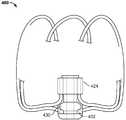
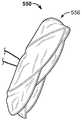
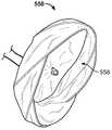
도 18a, 도 18b, 및 도 18c는, 재료의 관을 컷팅(예를 들어, 레이저 컷팅) 및 팽창시키는 것에 의해서 형성된 세장형 부재(552)를 가지는 장치 프레임을 포함하는 예시적인 장치(550)의 사시도이다. 본 예에서, 장치(550)가 6개의 세장형 부재(552)를 포함한다. 일반적으로, 장치(550)의 프레임이 본 명세서에서 설명된 다른 폐색 장치와 유사한 형상을 갖는다. 예를 들어, 커버링 구성요소(560)의 존재에도 불구하고, 장치 프레임의 면 섹션(554), 측방향을 향한 스커트 섹션(556), 및 반전된 섹션(558)을 도면에서 확인할 수 있다.18A, 18B, and 18C illustrate an
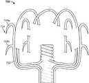
도 19는, 예를 들어, NiTi 관으로부터 레이저-컷팅된 이후의, 세장형의, 미리-열-경화된 구성의 예시적인 장치 프레임(900)의 도면이다. 프레임(900)은, 본 명세서에서 설명된 허브 부재에 상응할 수 있는, 프레임의 원위 단부 근처의 원통형 부재를 포함한다. 프레임이 또한, 세장형 부분이 본 명세서에서 설명된 프레임의 특징부를 형성하도록 특별한 구성으로 열 셋팅될 수 있는 관의 세장형 부분을 포함한다. 세장형 부분이 일반적으로 원통형 부재에서 종료된다. 프레임(900)은, 관의 나머지 부분이 본 명세서에서 제공된 일부 폐색 장치를 위한 프레임을 형성할 수 있도록 재료의 관이 어떻게 컷팅될 수 있는지에 관한 일반적인 예를 도시하기 위한 것이다.Figure 19 is a drawing of an
도 20 내지 도 25는 본 명세서에서 제공된 폐색 장치의 구조 내로 통합될 수 있는 특별한 폐색 장치 프레임 특징부를 강조하도록 작성된 것이다. 예를 들어, 일부 도면에서, 앵커 프레임 및/또는 다른 폐색 프레임의 구조가 강조되어 있다. 이러한 도면에서 강조된 특징부 중 하나 이상이 본 명세서의 다른 곳에서 설명된 임의의 폐색 장치 내에 포함될 수 있다는 것, 그리고 그러한 특징부(그리고 본 명세서에서 설명된 다른 특징부)가 혼합되고 합치되어, 본 개시의 범위 내에 전체적으로 포함되는 혼합 구조를 생성할 수 있다는 것을 이해하여야 할 것이다. 이러한 도면에서, 커버링 구성요소가 도시되어 있지 않거나 부분적인 커버링 구성요소 만이 도시되어 있고, 프레임의 일부 부분이 도시되어 있지 않으며, 그에 따라 강조된 프레임 특징부가 보다 용이하게 확인될 수 있다. 도 20 내지 도 25의 폐색 장치가 일부 실시예에서 커버링 구성요소와 조합될 수 있다는 것을 이해하여야 할 것이다. 커버링 구성요소가, 본 명세서에서 설명된 커버링 구성요소(104) 및/또는 임의의 다른 예시적인 커버링 구성요소를 참조하여 전술한 바와 같이, 임의의 또는 모든 특징, 특성, 성질 등을 공유할 수 있다.20-25 are intended to highlight a special occlusion device frame feature that may be incorporated into the structure of the occluding device provided herein. For example, in some drawings, the structure of an anchor frame and / or another occlusion frame is highlighted. It is to be understood that one or more of the highlighted features in this drawing may be included in any occlusion device described elsewhere herein and that such features (and other features described herein) It will be appreciated that a mixed structure may be created that is entirely within the scope of the disclosure. In this figure, no covering element is shown or only a partial covering element is shown, some parts of the frame are not shown, and accordingly the emphasized frame feature can be more easily identified. It should be appreciated that the occluding devices of Figures 20-25 may be combined with the covering component in some embodiments. The covering component may share any or all of its features, properties, properties, etc., as described above with reference to the
도 20은 본 명세서에서 설명된 유형의 예시적인 장치 프레임(700)의 일부의 개념도이다. 링 부재(702)는, 메인 장치 프레임이 이미 조립된 후에 미리-형성된 앵커(704)가 별개로 부가될 수 있게 허용할 수 있는 부착 홀을 포함한다. 볼 단부가 프레임 세장형 부재 및 앵커 세장형 부재 상에 도시되어 있고, 세장형 부재를 링 부재(702)에 고정하는데 도움을 줄 수 있다. 예를 들어, 접착제 또는 용접 조인트, 또는 다른 기계적인 앵커 구성요소가 또한 선택적으로 이용될 수 있다. 도시된 실시예에서, 내측 허브 부재가 아일릿(505)을 포함한다. 일부 실시예에서, 내측 허브 부재가, 비제한적으로, 링 부재, 및 관 부분 등과 같은 다른 유형의 허브 부재일 수 있을 것이다. 미리 형성된 앵커(704)가, 일부 구현예에서, 폐색 프레임의 와이어와 상이한 크기, 형상, 또는 재료의 와이어를 이용할 수 있다. 예를 들어, 일부 실시예에서, 미리-형성된 앵커(704)가 생흡수성 중합체로 형성될 수 있는 한편, 폐색 프레임이 금속 재료로 형성된다.20 is a conceptual diagram of a portion of an
도 21은 본 명세서에서 설명된 유형의 예시적인 장치 프레임(720)의 일부의 개념도이다. 프레임(720)이 앵커(724)를 가지는 앵커링 조립체(722)를 포함하고, 앵커링 조립체(722)가 재료의 관으로부터 컷팅된다. 예를 들어, 앵커링 조립체(722)가 니티놀의 관으로부터 컷팅될 수 있다. 조립체(722)의 하나 이상의 앵커 아암이 장치 프레임(720)(예를 들어, 앵커(724a, 724b) 참조)의 상이한 길이방향 위치들에 배치된 앵커들(724)를 포함한다. 이는, 예를 들어, 전개 중에, 스테이지형(staged) 고정을 도울 수 있다. 앵커(724a 및 724b)가 조립체의 동일한 아암 상에 위치되기 때문에, 예를 들어, 장치의 프로파일에 대한 부가(adding)가 없이도, 부가적인 앵커가 제공될 수 있을 것이다.21 is a conceptual illustration of a portion of an
일부 실시예에서, 앵커(724)(및 본 명세서에서 제공된 다른 앵커)가 가요성 및 탄성을 가지도록 설계되고, 그에 따라 앵커(724)가 전달 외장 내에서의 격납(containment)을 위한 낮은-프로파일 전달 구성으로 접힐 수 있고, 상당한 끌림 저항(dragging resistance)이 없이 전달 외장 내에서 병진운동될(translated) 수 있다. 전달 외장으로부터 전개될 때, 앵커(724)가, 전개 사이트에서 주변 조직과 결합하는 곡선형 구성(예를 들어, 도시된 바와 같거나, 도시된 것과 유사하다)으로 되돌아간다. 일부 구현예에서, 앵커(724)가 주변 조직을 천공하는 한편, 프레임(720)의 다른 부분은 앵커(724)의 침투 깊이를 제한하기 위한 탈지면(pledget)으로서 작용한다. 그러한 방식으로, 앵커(724)의 침투와 관련된 심낭삼출(pericardial effusion)의 위험이 감소될 수 있다. 일부 구현예에서, 앵커(724)가 침투 없이 주변 조직과 결합한다. 앵커(724)가 날카로운 지점을 가지는 것으로 도시되어 있지만, 일부 실시예에서, 앵커(724)(및 본 명세서에서 설명된 다른 앵커)가, 비제한적으로, 볼 단부, 미늘(barb), 비외상성(atraumatic) 단부, 후크, 양갈래형(bifurcated) 단부 등을 포함하는, 다른 유형의 단부를 가질 수 있다는 것을 이해하여야 할 것이다. 일부 실시예에서, 앵커들(724)의 개별적인 앵커가 상이한 유형의 단부들을 가질 수 있다.In some embodiments, the anchor 724 (and the other anchor provided herein) is designed to be flexible and resilient so that the
도 22는 본 명세서에서 설명된 유형의 예시적인 장치 프레임(740)의 일부의 개념도이다. 프레임(740)이, 그러한 프레임(740)의 원위 단부 근처의 반경방향 경직성을 증가시킬 수 있는, 원위 팽창 스텐트(stent) 섹션(742)을 포함한다. 증가된 반경방향 경직성이 일부 실시예에서 고정을 개선할 수 있을 것이다(도 23에서 앵커가 도시되지 않았으나, 스텐트 섹션(742)이 본 명세서에서 도시된 임의의 프레임과 조합될 수 있다). 스텐트 섹션(742)이, 프레임의 루프화된 영역 근처의 봉합사 또는 필름으로 프레임(740)의 원위 부분으로 느슨하게 부착될 수 있다. 스텐트 섹션(742)이, 예를 들어, 와이어 또는 컷팅 배관으로 형성될 수 있다.22 is a conceptual diagram of a portion of an
도 23은 본 명세서에서 설명된 유형의 예시적인 장치 프레임(760)의 일부의 개념도이다. 프레임(760)은 도 23의 프레임(740)과 유사하나, 스텐트 섹션(762)으로부터 연장하는 앵커 특징부를 가지는 스텐트 섹션(762)을 포함한다.23 is a conceptual illustration of a portion of an
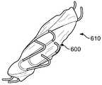
도 24는 본 명세서에서 설명된 유형의 예시적인 장치 프레임(780)의 일부의 개념도이다. 프레임(780)은 장치 프레임(780)의 원위 단부에서 프레임-내(in-frame) 앵커(782)를 포함한다. 앵커(782)가 루프를 포함하고, 조직의 침투를 피하거나 최소화하도록 설계된 패시브 고정(passive anchoring)을 제공한다. 다른 예에서, 앵커(782)가 조직을 침투하도록 설계된 날카로운 특징부(예를 들어, 적어도 하나의 후크, 미늘, 또는 날카로운 갈래(tine))를 포함할 수 있다. 대안으로서, 2013년 3월 15일자로 출원되고, 본 명세서에서 모든 목적을 위해서 그 전체가 참조로서 포함되며, 발명자가 Coby C. Larsen, Brandon A. Lurie, Steven J. Masters, Thomas R. McDaniel, 및 Stanislaw L. Zukowski인, "공간 충진 장치(Space Filling Devices)"인 가출원에서 설명된 마이크로-코일 앵커 특징부 중 임의의 것이 본 명세서에서 설명된 임의의 프레임 상의 세장형 프레임 부재의 임의의 적절한 부분에 부착될 수 있다.24 is a conceptual diagram of a portion of an
도 25는 본 명세서에서 설명된 유형의 예시적인 장치 프레임(800)의 일부의 개념도이다. 프레임(800)은, 앵커 허브 구성요소(804)로부터 원위측으로 연장하는 앵커(802)를 포함하고, 여기에서 앵커 허브 구성요소(804)가 본 예에서 커플링 구성요소(808)에 의해서 제2 허브 부재(806)에 커플링된다. 커플링 구성요소(808)가 그러한 구성요소(808)의 각각의 단부에서 볼 단부를 포함한다. 이러한 실시예에서, 앵커(802)가, 커플링 구성요소(808)의 이용에 의해서, 장치 프레임(800)의 나머지로부터 어느 정도의 독립성을 가지고 관절운동(articulate)할 수 있다.25 is a conceptual diagram of a portion of an
도 26a는 본 명세서에서 제공된 폐색 장치의 일부 실시예에 포함되는 예시적인 앵커 구성요소(600)를 도시한다. 예시적인 앵커 구성요소(600)가, 단부(602)의 복합 굽힘 각도(compound bend angle), 및 U-형상의 아암(604)을 포함하는, 도시된 대략적인 형상으로 굽혀지거나 형성된 와이어(예를 들어, NiTi 또는 스테인리스 스틸)이다. 앵커 구성요소(600)의 자유 단부가 날카로운 선단부, 비외상성 선단부, 미늘, 볼-단부, 또는 다른 유형의 선단부, 또는 그 조합을 포함할 수 있다.26A illustrates an
제1 및 제2 아암(604a 및 604b)이 폐색 장치 프레임의 세장형 부재에 연결될 수 있다. 예를 들어, 도 26b의 예에서 도시된 바와 같이, 앵커 구성요소(600)가 폐색 장치(610)의 세장형 부재(611 및 612)에 연결될 수 있다. 이러한 예시적인 구현예에서, 앵커 구성요소(600)의 제1 아암(604a)이 제1 세장형 부재(611)에 연결되고, 제2 아암(604b)이 제2 세장형 부재(612)에 연결된다. 도시된 바와 같이, 제1 아암(604a)이 그러한 제1 아암(604a)의 길이를 따라서 둘 이상의 위치들에서 제1 세장형 부재(611)에 연결된다. 제1 아암(604a)의 이러한 연결 방법은, 제1 아암(604a)이, 그러한 제1 아암(604a)의 실질적으로 전체 길이를 따라서 제1 세장형 부재(611)와 접촉되어 유지되도록 유도한다. 일부 실시예에서, 제2 아암(604b)이 단일 위치에서 제2 세장형 부재(612)에 연결된다. 그에 따라, 일부 실시예에서, 제2 아암(604b)이 제2 세장형 부재(612)에 대해 피봇될 수 있다. 제2 아암(604b)과 제2 세장형 부재(612) 사이의 그러한 피봇 가능한 연결은, 폐색 장치(610)가 상이한 크기들 또는 구성들로 팽창하거나 수축할 때, 앵커 구성요소(600)가 폐색 장치(610)의 프레임과 관련하여 그 위치를 재구성하게 허용할 수 있다. 앵커 구성요소(600)가 폐색 장치(610)의 프레임과 관련하여 그 위치를 재구성함에 따라, 단부(602)가 대체로 반경방향 외측 방향으로 지향되고, 그에 따라 장치를 주변 조직에 대해서 고정할 수 있는 능력을 유지한다. 또한, 단부(602)가 장치(610) 이동 가능성을 감소시키기 위해서 약간 근위 방향으로 지향된다. 이러한 특징부가 도 26c에 도시되어 있고, 그러한 도면은, 폐색 장치(610)가 부분적으로 붕괴된 구성에 있는 동안 고정을 제공하기 위한 배향의 그리고 단부가 노출된 앵커 구성요소(600)를 보여준다.The first and
도 27a 내지 도 27d는, 둘 이상의 허브 부재가 서로에 대해서 동심으로 또는 동축으로 위치되도록 허브 부재들을 포개기 위한 기술을 도시한다. 일부 실시예에서, 본 명세서에서 제공된 폐색 장치의 세장형 프레임 부재가 허브 부재에서 종료된다. 일부 실시예에서, 허브 부재가 아일릿(나선형 구성을 가지도록 권선된 하나 이상의 세장형 부재로 이루어진 코일)이다. 일부 실시예에서, 허브 부재가 링 부재(예를 들어, 도 10을 참조)이고, 그러한 링 부재에서 세장형 프레임 부재가 종래된다. 일부 실시예에서, 허브 부재가 크림프 조인트, 세장형 부재의 집속체를 둘러싸는 칼라이다. 일부 실시예에서, 크림프 조인트이, 세장형 부재를 칼라 내에서 구속(restrain)하기 위해서, 접착제, 용접부, 압력 끼워맞춤(press fit) 등을 포함할 수 있을 것이다. 세장형 부재의 보충적인 구속을 제공하기 위해서, 아일릿 및 링 부재가 또한 접착제, 용접부, 압력 끼워맞춤 등을 포함할 수 있을 것이다. 포개진 허브 구성은, 내피로성을 가질 뿐만 아니라, 낮은 프로파일로 붕괴될 수 있는 것과 같은 장점을 가지는 폐색 장치를 제공할 수 있다. 도 27a 내지 도 27d는 본 명세서에서 제공된 폐색 장치의 구조로 통합될 수 있는 특별한 폐색 장치 프레임 특징부를 강조하도록 작성된 것이다. 이러한 도면에서 강조된 특징부 중 하나 이상이 본 명세서의 다른 곳에서 설명된 임의의 폐색 장치 내에 포함될 수 있다는 것, 그리고 그러한 특징부(그리고 본 명세서에서 설명된 다른 특징부)가 혼합되고 합치되어(matched), 본 개시의 범위 내에 전체적으로 포함되는 혼합 구조를 생성할 수 있다는 것을 이해하여야 할 것이다. 이러한 도면에서, 커버링 구성요소가 도시되어 있지 않거나 부분적인 커버링 구성요소만이 도시되어 있고, 프레임의 일부 부분이 도시되어 있지 않으며, 그에 따라 강조된 프레임 특징부가 보다 용이하게 확인될 수 있다. 도 27a 내지 도 27d의 폐색 장치가 일부 실시예에서 커버링 구성요소와 조합될 수 있다는 것을 이해하여야 할 것이다. 커버링 구성요소가, 본 명세서에서 설명된 커버링 구성요소(104) 및/또는 임의의 다른 예시적인 커버링 구성요소를 참조하여 전술한 바와 같이, 임의의 또는 모든 특징, 특성, 성질 등을 공유할 수 있다.27A-27D illustrate a technique for superimposing hub members such that two or more hub members are coaxially or coaxially positioned with respect to each other. In some embodiments, the elongated frame member of the occlusion device provided herein is terminated at the hub member. In some embodiments, the hub member is an eyelet (a coil of one or more elongate members wound to have a helical configuration). In some embodiments, the hub member is a ring member (see, e.g., Fig. 10), and a elongated frame member in such a ring member is conventional. In some embodiments, the hub member is a collar that surrounds the crimp joint, the focusing member of the elongate member. In some embodiments, the crimp joint may include an adhesive, a weld, a press fit, etc., to restrain the elongate member in the collar. To provide additional constraint of the elongate member, the eyelet and ring member may also include an adhesive, a weld, a pressure fit, and the like. The overlapping hub configuration can provide an occlusion device that has the advantage of not only having fatigue resistance, but also being able to collapse into a low profile. Figures 27A-27D are intended to highlight special occlusion device frame features that may be incorporated into the structure of the occluding device provided herein. It is to be understood that one or more of the features highlighted in these figures may be included in any occlusion device described elsewhere herein and that such features (and other features described herein) are matched ), It is to be understood that a mixed structure may be created that is entirely within the scope of this disclosure. In this figure, no covering element is shown or only a partial covering element is shown, and some parts of the frame are not shown, so that the emphasized frame features can be more easily identified. It should be appreciated that the occlusion device of Figures 27A-D may be combined with the covering component in some embodiments. The covering component may share any or all of its features, properties, properties, etc., as described above with reference to the
도 27a는 포개진 아일릿(622 및 624)을 가지는 폐색 장치(620)를 도시한다. 즉, 제1 아일릿(622)이 제2 아일릿(624)에 의해서 형성된 공간 내에 위치된다. 도 27b는, 링 부재(634) 내에 포개진 아일릿(632)을 가지는 폐색 장치(630)를 도시한다. 도 27c는 링 부재(644) 내에 포개진 크림프 조인트(642)를 가지는 폐색 장치(640)를 도시한다. 도 27d는 아일릿(654) 내에 포개진 링 부재(652)를 가지는 폐색 장치(650)를 도시한다. 링 부재, 아일릿, 및 크림프 조인트의 임의 조합이 본 개시의 범위 내에서 고려된다는 것을 이해하여야 할 것이다. 아일릿을 가지는 일부 실시예에서, 아일릿을 구성하는 세장형 요소의 일부 또는 전부가 용접(예를 들어, 레이저 용접)에 의해서, 또는 다른 기술(예를 들어, 접착제 등의 이용)에 의해서 아일릿 영역 내에서 결합될 수 있을 것이다. 포개진 아일릿들을 가지는 일부 실시예에서, 그러한 기술을 이용하여, 내측 아일릿 및 외측 아일릿을 함께 결합하지는 않으면서, 내측 아일릿 및/또는 외측 아일릿의 세장형 요소의 일부 또는 전부를 개별적으로 결합할 수 있다. 포개진 아일릿들을 가지는 일부 실시예에서, 그러한 기술을 이용하여, 내측 아일릿 및 외측 아일릿의 세장형 요소들의 일부 또는 전부를 함께 결합할 수 있다. 하나 이상의 아일릿을 포함하는 본 명세서에서 제공된 임의의 폐색 장치가 그러한 방식으로 결합된 아일릿(들)의 세장형 요소의 일부 또는 전부를 가질 수 있다.Figure 27A shows a
도 28a 내지 도 28c는 포개진 아일릿을 가지는 폐색 장치의 프레임을 형성하기 위한 기술을 도시한다. 도 28a은, 제1 아일릿(662) 및 제2 아일릿(664)을 포함하는 세장형 부재(660)의 조립체를 도시한다. 세장형 부재(660)의 조립체가, 본 명세서의 다른 곳에서 설명된 바와 같은 지그 및/또는 맨드릴을 이용하여 세장형 부재를 권선하는 프로세스의 결과일 수 있다. 세장형 부재(660)의 조립체가 제1 아일릿(662) 및 제2 아일릿(664)를 포함한다. 일부 실시예에서, 아일릿이 포함되지만, 다른 실시예에서, 다른 유형의 허브가, 아일릿 대신에 또는 아일릿에 부가적으로, 포함될 수 있다.28A to 28C show a technique for forming a frame of an occluding device having a collapsed eyelet. 28A shows an assembly of a
도 28b는 포개지는 허브를 위한 기술의 중간 단계를 도시한다. 도 28a에 도시된 세장형 부재(660)의 조립체의 구성으로부터 도 28b에 도시된 세장형 부재(660)의 조립체의 구성으로 변화시키기 위해서, 제1 및 제2 아일릿(662 및 664)이 개별적으로 약 180도로, 그리고 화살표(663 및 665)에 의해서 표시된 바와 같은 반대 방향들로 회전된다. 그렇게 하는데 있어서, 세장형 부재(660)가 서로 꼬이지 않는다.FIG. 28B shows an intermediate stage of the technique for the superimposing hub. In order to change from the configuration of the assembly of the
도 28c는 허브 부재들을 포개기 위한 기술의 최종 단계를 도시한다. 즉, 내측 아일릿(662)이 제2 허브(664)에 의해서 형성된 내부 공간 내에 실질적으로 배치된다. 일부 실시예에서, 제2 허브(664)가 제1 허브(662)에 의해서 형성된 내부 공간 내에 실질적으로 배치될 수 있다.Figure 28c shows the final step of the technique for superimposing hub members. That is, the
도 29a 및 도 29b는, 포개진 아일릿들을 가지는 폐색 장치를 제조하기 위해서 세장형 부재를 권선하기 위해서 이용될 수 있는 공구(670)를 도시한다. 권선 패턴이 권선 시작 디스크(672)에서 시작되고 기둥(674) 아래로 아일릿을 권선한다. 이어서, 세장형 부재가 권선되고, 각각의 세장형 부재는 유사하나 구분되게 상이한 경로(본 예에서, 약 216 도)를 따른다. 이어서, 기둥의 하단에서 시작하여, 위쪽으로 초기의 아일릿 주위에 다른 아일릿을 형성하기 위해서, 세장형 부재가 권선된다.29A and 29B illustrate a
도 30a 내지 도 30d는, 원위 앵커링 부재를 포함하는 폐색 장치의 실시예를 제공한다. 여러 가지 유형의 원위 앵커링 부재가 도시되어 있다. 도 30a 내지 도 30d는 본 명세서에서 제공된 폐색 장치의 구조 내로 통합될 수 있는 특별한 폐색 장치 프레임 특징부를 강조하도록 작성된 것이다. 이러한 도면에서 강조된 특징부 중 하나 이상이 본 명세서의 다른 곳에서 설명된 임의의 폐색 장치 내에 포함될 수 있다는 것, 그리고 그러한 특징부(그리고 본 명세서에서 설명된 다른 특징부)가 혼합되고 합치되어, 본 개시의 범위 내에 전체적으로 포함되는 혼합 구조를 생성할 수 있다는 것을 이해하여야 할 것이다. 이러한 도면에서, 커버링 구성요소 및 프레임의 일부 부분이 도시되어 있지 않으며, 그에 따라 강조된 프레임 특징부가 보다 용이하게 확인될 수 있다.30A-30D provide an embodiment of a closure device including a distal anchoring member. Various types of distal anchoring members are shown. 30A-30D are intended to highlight a special occlusion device frame feature that may be incorporated into the structure of the occluding device provided herein. It is to be understood that one or more of the highlighted features in this drawing may be included in any occlusion device described elsewhere herein and that such features (and other features described herein) It will be appreciated that a mixed structure may be created that is entirely within the scope of the disclosure. In this figure, the covering component and some parts of the frame are not shown, so that the emphasized frame feature can be more easily identified.
도 30a는 폐색 부재(681) 및 원위 앵커링 부재(686)를 포함하는 폐색 장치(680)를 도시한다. 본 명세서에서 설명된 일부 다른 폐색 장치에서와 같이, 폐색 부재(681)가 폐색 면(682), 측방향을 향한 스커트(683), 반전된 섹션(684), 및 허브 부재(685)(일부 실시예에서, 포개진 허브 조립체일 수 있으나, 다른 실시예에서 허브들이 포개지지 않는다)를 포함한다.30A shows a
일부 실시예에서, 원위 앵커링 부재(686)가, 컷팅되고 이어서 팽창되는 재료로 구성된다. 예를 들어, 일부 실시예에서, 원위 앵커링 부재(686)가, 레이저-컷팅되고 이어서 실질적으로 도시된 바와 같은 구성으로 팽창되는(그리고 일부 실시예에서 열-세팅되는), 재료의 관으로 제조된다. 일부 실시예에서, NiTi가 재료로서 이용되나, 스테인리스 스틸 및 중합체와 같은 다른 재료가 또한, NiTi 대신에 또는 NiTi와 조합되어, 이용될 수 있을 것이다. 원위 앵커링 부재(686)의 구조가, 원위 앵커링 부재(686)로부터 주변 조직으로의 반경방향 힘의 인가를 도울 수 있고, 이는 폐색 장치(680)의 고정 성능을 보조할 수 있다. 또한, 원위 앵커링 부재(686)의 구성이 곡선화된 세장형 부재로 제조된 부분을 포함한다. 그러한 곡선화된 부분이 축방향 및 반경방향 가요성 및 스프링성(springiness)을 제공할 수 있고, 그에 의해서 앵커 프레임이 환자의 해부조직 내에서의 장치 이동에 대해서 저항한다. 또한, 일부 실시예에서, 원위 앵커링 부재(686)가, 주변 조직과 관련하여 폐색 장치(680)의 고정을 제공하기 위해서 조직에 맞대지거나 침투할 수 있는 복수의 자유 단부(687)를 포함한다.In some embodiments, the
일부 실시예에서, 폐색 부재(681) 및 원위 앵커링 부재(686)가 커플링 요소(689)에 의해서 함께 커플링될 수 있을 것이다. 일부 예에서, 커플링 요소가 FEP와 같은 접착제, 또는 용접부일 수 있을 것이다. 도시된 예에서, 커플링 요소(689)가, 조인트, 리벳(예를 들어, 바벨 리벳), 또는 여러 가지 유형의 캐치 부재와 같은, 기계적인 커플링 요소이다. 커플링 요소가 장치 프레임의 길이방향 축선을 따라서 폐색 부재 허브(685) 및 앵커링 부재 허브(688)를 실질적으로 정렬시킬 수 있을 것이다. 일부 예에서, 폐색 부재 허브(685) 및 앵커링 부재 허브(688)가 장치 프레임의 길이방향 축선을 따라서 동심으로 정렬될 수 있을 것이다.In some embodiments, the occluding
일부 실시예에서, 커플링 요소(689)가 폐색 부재(681)와 원위 앵커링 부재(686) 사이의 상대적인 이동을 허용할 수 있을 것이다. 예를 들어, 폐색 부재(681) 및 원위 앵커링 부재(686)가 서로에 대해서 축방향으로 이동하도록, 또는 서로에 대해서 회전하도록 허용될 수 있을 것이다.In some embodiments,
도 30b는, 원위 앵커링 부재(696)를 포함하는 폐색 장치(690)의 다른 실시예를 도시한다. 본 명세서에서 설명된 일부 다른 폐색 장치에서와 같이, 폐색 부재(691)가 폐색 면(692), 측방향을 향한 스커트(693), 반전된 섹션(694), 및 허브 부재(695)(일부 실시예에서, 포개진 허브 조립체일 수 있으나, 다른 실시예에서 허브들이 포개지지 않는다)를 포함한다.30B illustrates another embodiment of a
일부 실시예에서, 원위 앵커링 부재(696)가, 링 허브 부재(698)에서의 일 단부에서 그리고 볼 단부(697)에서의 타 단부에서 종료되는 복수의 세장형 부재(예를 들어, 696a, 696b, 및 696c)로 제조된다. 볼 단부(697)가, 예를 들어, 마찰, 압력, 또는 얽힘(entanglement)에 의해서, 신체 조직과 비외상적으로 결합하도록 그리고 장치(690)를 제 위치에서 고정하도록 구성된다. 일부 예에서, 볼 단부(697)가 레이저 용접에 의해서 정착(fixation) 앵커 와이어의 단부 상에 형성될 수 있을 것이다. 일부 구현예에서, 볼 단부(697)가 고정을 제공할 수 있을 것이고, 천공 또는 심낭삼출 가능성을 감소시킬 수 있을 것이다. 일반적으로, 일부 구현예에서, 볼 단부(697) 또는 본 명세서에서 설명된 다른 피동적 앵커 특징부가, 날카로운 연부를 가지는 일부 능동적 고정 요소에 대비하여, 전달 외장의 내측 표면 상에서 적은 마찰을 유발할 수 있을 것이고, 이는, 일부 경우에, 전달 시스템에 대한 미립자화(particulation)를 감소시킬 수 있을 것이다. 일부 실시예에서, 볼 단부(697)의 직경이 프레임 앵커 와이어의 직경의 약 2배일 수 있을 것이다. 일부 예에서, 볼 단부(697)의 직경이 프레임 앵커 와이어의 직경의 약 1 x (단지 둥근 와이어 단부) 내지 약 2x의 범위일 수 있을 것이고, 예를 들어, 그러한 직경이 프레임 앵커 와이어의 약 1.5x일 수 있거나, 프레임 앵커 와이어의 직경의 약 1.6x, 1.7x, 1.8x, 또는 1.9x일 수 있을 것이다. 볼 단부(697)가, 예를 들어, 프레임 앵커 와이어의 단부로 레이저 펄스를 인가하는 것에 의해서 생성될 수 있을 것이다. 예를 들어, 일부 실시예에서, 구형 부재 또는 볼 단부(697)가, 정밀 레이저 용접 기술을 이용하여(예를 들어, Nd:YAG 레이저를 이용하여) 프레임 앵커 와이어의 단부 상에 직접 형성될 수 있을 것이다.In some embodiments, a
일부 실시예에서, 폐색 부재(691) 및 원위 앵커링 부재(696)가 커플링 요소(699)에 의해서 함께 커플링될 수 있을 것이다. 일부 예에서, 커플링 요소가 FEP와 같은 접착제, 또는 용접부일 수 있을 것이다. 도시된 예에서, 커플링 요소(699)가, 조인트, 리벳(예를 들어, 바벨 리벳), 또는 여러 가지 유형의 캐치 부재와 같은, 기계적인 커플링 요소이다. 일부 실시예에서, 커플링 요소(699)가 폐색 부재(691)와 원위 앵커링 부재(696) 사이의 상대적인 이동을 허용할 수 있을 것이다. 예를 들어, 폐색 부재(691) 및 원위 앵커링 부재(696)가 서로에 대해서 축방향으로 이동하도록, 또는 서로에 대해서 회전하도록 허용될 수 있을 것이다.In some embodiments, the occluding
도 31a는, 원위 앵커링 부재(816)를 포함하는 폐색 장치(810)의 다른 실시예를 도시한다. 본 명세서에서 설명된 다른 폐색 장치에서와 같이, 폐색 부재(811)가 폐색 면(812), 측방향을 향한 스커트(813), 반전된 섹션(814), 및 허브 부재(815)(일부 실시예에서, 포개진 허브 조립체일 수 있으나, 다른 실시예에서 허브들이 포개지지 않는다)를 포함한다.31A shows another embodiment of an
일부 실시예에서, 원위 앵커링 부재(816)가, 컷팅되고 이어서 팽창되는 재료로 구성된다. 예를 들어, 일부 실시예에서, 원위 앵커링 부재(816)가, 레이저-컷팅되고 이어서 실질적으로 도시된 바와 같은 구성으로 팽창되는(그리고 일부 실시예에서 열-세팅되는), 재료의 관으로 제조된다. 일부 실시예에서, NiTi가 재료로서 이용되나, 스테인리스 스틸 및 중합체와 같은 다른 재료가 또한 이용될 수 있을 것이다.In some embodiments, the
일부 실시예에서, 폐색 부재(811) 및 원위 앵커링 부재(816)가 커플링 요소(819)에 의해서 함께 커플링될 수 있을 것이다. 폐색 장치(680) 및 폐색 장치(690)와 대조적으로, 폐색 장치(810)에서, 허브(815 및 818)가 커플링되지 않는다. 오히려, 원위 앵커링 부재(816) 및 폐색 부재(811)의 둘레가 복수의 봉합사 매듭(819)에 의해서 함께 커플링될 수 있을 것이다. 일부 실시예에서, 허브(815 및 818)가 또한 봉합사를 이용하여 함께 묶일 수(tethered) 있다. 봉합사 매듭(819)이 세장형 부재(예를 들어, 816a, 816b, 816c)를 폐색 부재(811)의 세장형 부재로, 또는 폐색 부재(811)의 커버링 구성요소로, 또는 폐색 부재(811)의 세장형 부재 및 커버링 구성요소 모두로 잡아 매고(lash) 속박한다.In some embodiments, the occluding
복수의 봉합사 매듭(819)을 이용하여 폐색 부재(811) 및 원위 앵커링 부재(816)를 커플링시키는 이러한 기술은, 전달 외장 내의 배치를 위한 매우 낮은 프로파일로 폐색 장치(810)가 붕괴되게 할 수 있을 것이다. 또한, 일부 실시예에서, 원위 앵커링 부재(816) 및 폐색 부재(811)의 둘레들을 커플링시키기 위해서 복수의 봉합사 매듭(819)을 이용하는 것이, 전달 외장 내로의 적재 중에, 전개 중에 그리고 전개 후에, 폐색 장치(810)의 안정성을 향상시킬 수 있을 것이다.This technique of using the plurality of
도 31b는, 원위 앵커링 부재(826)를 포함하는 폐색 장치(820)의 다른 실시예를 도시한다. 본 명세서에서 설명된 다른 폐색 장치에서와 같이, 폐색 부재(821)가 폐색 면(822), 측방향을 향한 스커트(823), 반전된 섹션(824), 및 허브 부재(825)(일부 실시예에서, 포개진 허브 조립체일 수 있으나, 다른 실시예에서 허브들이 포개지지 않는다)를 포함한다.Fig. 31B shows another embodiment of an
일부 실시예에서, 폐색 부재(821) 및 원위 앵커링 부재(826)가, 그 교차부에서 원위 앵커링 부재(826) 및 폐색 부재(821)의 둘레의 일부 또는 전부 주위의 나선형 경로를 형성하는 오버핸드 러닝 스티치(overhand running stitch)(829)에 의해서 함께 커플링될 수 있을 것이다. 폐색 장치(680) 및 폐색 장치(690)와 대조적으로, 폐색 장치(820)에서, 허브(825 및 828)가 커플링되지 않는다. 오히려, 원위 앵커링 부재(826) 및 폐색 부재(821)의 둘레들이 오버핸드 러닝 스티치(829)에 의해서 함께 커플링될 수 있을 것이다. 일부 실시예에서, 허브(825 및 828)가 또한 봉합사를 이용하여 함께 묶일 수 있다. 오버핸드 러닝 스티치(829)가 세장형 부재(예를 들어, 826a, 826b, 826c)를 폐색 부재(821)의 세장형 부재에, 또는 폐색 부재(821)의 커버링 구성요소에, 또는 폐색 부재(821)의 세장형 부재 및 커버링 구성요소 모두에 잡아 매고 속박한다.In some embodiments, the
오버핸드 러닝 스티치(829)를 이용하여 폐색 부재(821) 및 원위 앵커링 부재(826)를 커플링시키는 이러한 기술은, 전달 외장 내의 배치를 위한 매우 낮은 프로파일로 폐색 장치(820)가 붕괴되게 할 수 있을 것이다. 또한, 일부 실시예에서, 원위 앵커링 부재(826) 및 폐색 부재(821)의 둘레들을 커플링시키기 위해서 오버핸드 러닝 스티치(829)를 이용하는 것이, 전달 외장 내로의 적재 중에, 전개 중에 그리고 전개 후에, 폐색 장치(820)의 안정성을 향상시킬 수 있을 것이다. 또한, 원위 앵커링 부재(826)를 폐색 부재(821)에 부착하는 것이, 일부 실시예에서, 폐색 장치(820)를 해부학적 공간(예를 들어, LAA) 내에서 센터링시키는 것을 도울 수 있다.This technique of using the
도 32는, 폐색 부재(831), 및 그러한 폐색 부재(831) 및 원위 앵커링 부재(836)를 포함하는 다른 폐색 장치(830)의 측면 사시도를 도시한다. 이러한 도면에서, 원위 앵커링 부재(836)의 세장형 부재(837)의 단부 부분만이 확인될 수 있다. 원위 앵커링 부재(836)가 도 30a, 도 30b, 도 31a, 및 도 31b의 원위 앵커링 부재(686, 696, 816, 및 826) 중 임의의 것과 유사할 수 있고; 도 33a 내지 도 33c의 원위 앵커링 부재(846)와 유사할 수 있으며; 그리고 임의의 다른 유사한 구조를 가질 수 있다는 것을 이해하여야 할 것이다.32 shows a side perspective view of an
원위 앵커링 부재(836)의 세장형 부재(837)가 폐색 부재(831)로부터 대체로 반경방향으로 돌출한다는 것을 확인할 수 있을 것이다. 특히, 일부 실시예에서, 원위 앵커링 부재(836)의 세장형 부재(837)가 폐색 부재(831)의 커버링 구성요소(832)를 통해서 돌출한다. 또한, 일부 실시예에서, 원위 앵커링 부재(836)의 세장형 부재(837)가, (도 32에 도시된 바와 같이) 폐색 부재(831)의 세장형 부재(834)에 의해서 형성된 간극 공간을 통해서 폐색 부재(831)로부터 돌출한다.It will be appreciated that the
원위 앵커링 부재(836)의 세장형 부재(837)를 폐색 부재(831)의 커버링 구성요소(832) 및 세장형 부재(834)에 잡아 매고 속박하기 위한 봉합 기술이 폐색 장치(830)를 위해서 이용될 수 있다. 예를 들어, 일부 실시예에서, 봉합사 매듭(도 31a 참조)을 이용하여 원위 앵커링 부재(836)의 세장형 부재(837)를 폐색 부재(831)의 세장형 부재(834)에 잡아 매고 속박할 수 있다. 일부 실시예에서, 오버핸드 러닝 스티치 기술(도 31b 참조)을 이용하여 원위 앵커링 부재(836)의 세장형 부재(837)를 폐색 부재(831)의 커버링 구성요소(832) 및 세장형 부재(834)에 잡아 매고 속박할 수 있다. 일부 실시예에서, 그러한 기술 및 다른 기술(예를 들어, 클립, 접착제, 용접 등)의 조합을 이용하여, 원위 앵커링 부재(836)의 세장형 부재(837)를 폐색 부재(831)의 커버링 구성요소(832) 및 세장형 부재(834)에 잡아 매고 속박할 수 있다.A sealing technique for gripping and constraining the
도 33a 내지 도 33d는 다른 폐색 장치(840)를 도시한다. 폐색 장치(840)는 폐색 부재(841) 및 원위 앵커링 부재(846)를 포함한다. 폐색 부재(841)가 폐색 면(842), 측방향을 향한 스커트(843), 커버링 구성요소(844), 및 반전된 섹션(845)을 포함한다.33A to 33D show another
원위 앵커링 부재(846)가 복수의 세장형 부재(847)로 이루어진 프레임 및 기판(848)을 포함한다. 기판(848)이, 세장형 부재(847)에 대해서, 적어도 부분적으로 (예를 들어, FEP를 이용하여) 결합되거나, 라미네이팅되거나, 또는 달리 부착된다. 일부 실시예에서, 기판은 조밀화된(densified) ePTFE일 수 있다. 일부 실시예에서, 비제한적으로 PTFE, 폴리에스테르, DACRON, 실리콘, 우레탄, 또는 다른 생체적합성 중합체, 또는 그 조합을 포함하는, 다른 유형의 시트 재료가 이용될 수 있다.The
일부 실시예에서, 복수의 세장형 부재(847)로 이루어진 프레임 및 기판(848)을 포함하는 원위 앵커링 부재(846)가 측방향을 향한 스커트(843)의 원위 단부 근처에서 폐색 부재(841)에 부착될 수 있다. 예를 들어, 일부 실시예에서, 원위 앵커링 부재(846)의 복수의 세장형 부재(847)로 이루어진 프레임 및 기판(848)이, 도 31a, 도 31b, 및 도 32를 참조하여 설명된 바와 같이, (예를 들어, 봉합사 매듭, 오버핸드 러닝 스티치 등을 이용하여) 폐색 부재(841)의 커버링(844) 및/또는 폐색 부재(841)의 세장형 부재에 부착된다. 일부 실시예에서, 기판(848)이 부가적인 표면을 제공하고, 그러한 부가적인 표면을 이용하여 원위 앵커링 부재(846)가 폐색 부재(841)에 부착된다. 예를 들어, 도 33b에서, 봉합사 요소(849)를 이용하여 기판(848)을 커버링 구성요소(844)에 스티칭한다. 봉합사 요소(849)가 또한 세장형 부재(847)를 폐색 부재(841)의 세장형 부재로 그리고 커버링 구성요소(844)에 잡아 매기 위해서 이용될 수 있다. 그러한 방식으로, 원위 앵커링 부재(846)가, 선택적으로, 측방향을 향한 스커트(843)의 원위 단부 근처에서 폐색 부재(841)에 확실하게 부착될 수 있다.In some embodiments, a
도 34a, 도 34c, 및 도 34d는 원위 앵커링 부재(856)를 포함하는 다른 예시적인 폐색 장치(850)를 도시한다. 도 34b는, 폐색 장치(850)의 구성요소 부분일 수 있는 예시적인 원위 앵커링 부재(856)를 도시한다.Figs. 34A, 34C, and 34D illustrate another
도 34b를 참조하면, 예시적인 원위 앵커링 부재(856)가 앵커링 부분(857), 근위 구근형(bulbous) 부분(858), 및 허브(859a 및 859b)를 가지는 프레임을 포함할 수 있다. 원위 앵커링 부재(856)가, 컷팅되고 팽창되는 재료로(도 34a, 도 34c, 및 도 34d에 도시된 바와 같다), 또는 여러 가지 유형의 허브를 이용하여 함께 커플링되는 세장형 부재로(도 34b에 도시된 바와 같다) 제조될 수 있다.34B, an exemplary
도 34a, 도 34c, 및 도 34d를 참조하면, 예시적인 폐색 장치(850)가 원위 앵커링 부재(856) 및 폐색 부재(851)를 포함한다. 폐색 부재(851)가 허브(851a), 폐색 면(852), 측방향을 향한 스커트(853), 커버링 구성요소(854), 및 반전된 섹션(855)을 포함한다.34A, 34C, and 34D, an
일부 실시예에서, 원위 앵커링 부재(856)가 이하의 방식 중 하나 이상으로 폐색 부재(851)에 커플링된다. 예를 들어, 원위 앵커링 부재(856)의 허브(859a)가 폐색 부재(851)의 허브(851a)에 커플링될 수 있다. 그러한 허브(859a 및 851a)의 커플링이, (예를 들어, 접착제(FEP와 같음), 용접부, 기계적 커플링 요소(예를 들어, 조인트, 리벳(예를 들어, 바벨 리벳)), 또는 여러 가지 유형의 캐치 부재를 이용하여), 본 명세서의 다른 곳에서 설명된 허브를 커플링하기 위한 여러 가지 기술을 이용하여 달성될 수 있다. 부가적으로, 또는 대안으로서, 도 31a, 도 31b, 및 도 32를 참조하여 설명된 봉합사 기술을 이용하여(예를 들어, 봉합사 매듭, 오버핸드 러닝 스티치 등을 이용하여), 원위 앵커링 부재(856)가 폐색 부재(851)에 커플링될 수 있다. 도 33a 내지 도 33d를 참조하여 설명된 바와 같이, 기판이 원위 앵커링 부재(856) 상에 포함될 수 있을 것이다. 부가적으로, 또는 대안으로서, 구근형 부분(858) 및 폐색 부재(851)의 내부 사이의 억지 끼워맞춤(interference fit)을 이용하여, 원위 앵커링 부재(856)가 폐색 부재(851)에 커플링될 수 있다. 즉, 구근형 부분(858)의 외경이 폐색 부재(851)의 내부보다 클 수 있고, 그에 의해서 원위 앵커링 부재(856)와 폐색 부재(851) 사이의 커플링을 제공할 수 있다.In some embodiments, the
도 35 및 36은 다른 예시적인 폐색 장치 프레임(860)을 측면도 및 근위측 사시도로 각각 도시한다. 도시된 실시예에서, 폐색 장치 프레임(860)이, 그러한 폐색 장치 프레임(860)을 형성하기 위해서 권선된 복수의 세장형 부재(862)를 포함한다. 세장형 부재(862)가, 세장형 부재(102) 및/또는 본 명세서에서 설명된 임의의 다른 세장형 부재를 참조하여 전술한 바와 같이, 임의의 또는 모든 특징, 특성, 성질 등을 공유할 수 있다. 일부 실시예에서, 세장형 부재(862)가 전술한 바와 같이 관 컷팅 프로세스로부터 형성될 수 있다.35 and 36 show another exemplary
폐색 장치 프레임(860)의 도시된 실시예에서, 세장형 부재(862)가 폐색 면(870), 측방향을 향한 스커트(872), 반전된 섹션(876), 및 포개진 아일릿(868)인 허브 부재(868)를 형성한다. 폐색 장치 프레임(860)의 일부 실시예에서, 폐색 면(870), 측방향을 향한 스커트(872), 반전된 섹션(876), 및 허브 부재(868)가 본 명세서에서 제공된 모든 다른 폐색 장치를 참조하여 전술한 바와 같은 임의의 또는 모든 특징, 특성, 성질 등을 공유할 수 있다는 것을 이해하여야 할 것이다.In the illustrated embodiment of the
폐색 장치 프레임(860)이 일부 실시예에서 커버링 구성요소와 조합될 수 있다. 커버링 구성요소가, 커버링 구성요소(104) 및/또는 본 명세서에서 설명된 임의의 예시적인 커버링 구성요소를 참조하여 전술한 바와 같은, 특징, 특성, 성질 등을 공유할 수 있다.The
폐색 장치 프레임(860)의 도시된 실시예가 허브 부재로서 포개진 아일릿(868)을 포함하지만, 폐색 장치 프레임(860)의 일부 실시예에서, 허브 부재의 하나 또는 양자 모두가 본 명세서의 다른 곳에서 설명된 다른 유형의 허브 부재 중 임의의 것(예를 들어, 링 부재, 크림프 조인트, 관 부분, 및 그 조합)일 수 있을 것이다.Although the illustrated embodiment of the
도 37은, 본 명세서에서 제공된 폐색 장치의 일부로서 포함될 수 있는 예시적인 앵커 프레임(880)을 도시한다. 도시된 실시예에서, 앵커 프레임(880)이, 그러한 앵커 프레임(880)을 형성하기 위해서 권선되는 복수의 세장형 부재를 포함한다. 세장형 부재(882)가, 본 명세서에서 설명된 세장형 부재(102) 및/또는 본 명세서에서 설명된 임의의 다른 예시적인 세장형 부재를 참조하여 전술한 바와 같이, 임의의 또는 모든 특징, 특성, 성질 등을 공유할 수 있다. 일부 실시예에서, 세장형 부재(882)가 전술된 바와 같은 관 컷팅 프로세스를 이용하여 형성될 수 있다.37 shows an
앵커 프레임(880)의 도시된 실시예에서, 세장형 부재(882)가 앵커 아암(884), 및 아일릿(886)인 허브 부재(886)를 형성한다. 앵커 프레임(880)의 일부 실시예에서, 앵커 아암(884) 및 허브 부재(886)가 본 명세서에서 제공된 모든 다른 앵커 프레임을 참조하여 전술한 바와 같은 임의의 또는 모든 특징, 특성, 성질 등을 공유할 수 있다는 것을 이해하여야 할 것이다. 예를 들어, 앵커 아암(884)의 자유 단부가, 앵커 특징부(600)를 참조하여 전술한 바와 같은, 날카로운 선단부, 비외상성 선단부, 미늘, 볼-단부, 또는 다른 유형의 선단부, 또는 그 조합을 포함할 수 있다. 앵커 프레임(880)의 도시된 실시예에서, 앵커 아암(884)이 대체로 나선형인 경로를 따라서 연장한다. 일부 실시예에서, 앵커 아암(884)이, 비제한적으로, 아일릿(886)의 중심 축선에 평행한, 도시된 것으로부터 방향이 반전된 나선형 경로, 여러 가지 상이한 피치 각도의 나선형 경로, 폐색 장치 프레임의 세장형 요소 주위로 권선된, 파동형(wavy) 경로 등, 그리고 그 조합과 같은 다른 경로를 따라서 연장할 수 있다.In the illustrated embodiment of the
도 38 및 도 39는, 본 명세서에서 제공된 폐색 장치의 일부로서 포함될 수 있는 다른 예시적인 앵커 프레임(890)의 측면도 및 근위측 사시도를 각각 도시한다. 도시된 실시예에서, 앵커 프레임(890)이, 전술한 바와 같은 관 컷팅 프로세스로부터 형성된 복수의 세장형 부재(892)를 포함한다. 세장형 부재(892)가, 본 명세서에서 설명된 세장형 부재(102) 및/또는 임의의 다른 예시적인 세장형 부재를 참조하여 전술한 바와 같이, 임의의 또는 모든 특징, 특성, 성질 등을 공유할 수 있다. 일부 실시예에서, 세장형 부재(892)가 전술된 바와 같이 앵커 프레임(890)을 형성하기 위해서 권선될 수 있다.38 and 39 each show a side view and a proximal side perspective view of another
앵커 프레임(890)의 도시된 실시예에서, 세장형 부재(892)가 하나 이상의 앵커 아암(894), 및 관의 부분을 포함하는 허브 부재(896)를 형성한다. 반경방향 받침대(893)가 허브 부재(896)로부터 반경방향 외측으로 연장하고 이어서 앵커 아암(894)으로 전이된다. 앵커 프레임(890)의 일부 실시예에서, 앵커 아암(894), 반경방향 받침대(893), 및 허브 부재(896)가 본 명세서에서 제공된 모든 다른 앵커 프레임을 참조하여 전술한 바와 같은 임의의 또는 모든 특징, 특성, 성질 등을 공유할 수 있다는 것을 이해하여야 할 것이다. 예를 들어, 앵커 아암(894)의 자유 단부가, 앵커 특징부(600)를 참조하여 전술한 바와 같은, 날카로운 선단부, 비외상성 선단부, 미늘, 볼-단부, 또는 다른 유형의 선단부, 또는 그 조합을 포함할 수 있다. 앵커 프레임(890)의 도시된 실시예에서, 앵커 아암(894)이 대체로 나선형인 경로를 따라서 연장한다. 일부 실시예에서, 앵커 아암(894)이, 비제한적으로, 아일릿(896)의 중심 축선에 평행한, 도시된 것으로부터 방향이 반전된 나선형 경로, 여러 가지 상이한 피치 각도의 나선형 경로, 파동형 경로 등, 그리고 그 조합과 같은 다른 경로를 따라서 연장할 수 있다.In the illustrated embodiment of the
도 40 및 도 41은, 예시적인 폐색 장치(900)의 측면도 및 근위측 사시도를 각각 도시한다. 폐색 장치(900)가 (전술한 바와 같은) 앵커 프레임(890)과 커플링된 (전술한 바와 같은) 폐색 장치 프레임(860)을 포함한다. 일부 실시예에서, 폐색 장치(900)가, 앵커 프레임(880)(도 37 참조), 또는 본 명세서에서 제공된 다른 앵커 프레임과 커플링된 폐색 장치 프레임(860)을 포함한다. 일부 실시예에서, 폐색 장치(900)가, 본 명세서에서 제공된 다른 앵커 프레임과 커플링된 앵커 프레임(890)(또는 앵커 프레임(880))을 포함한다.Figs. 40 and 41 show a side view and a proximal side perspective view respectively of an
폐색 장치(900)가 일부 실시예에서 커버링 구성요소와 조합될 수 있다는 것을 이해하여야 할 것이다. 커버링 구성요소가, 본 명세서에서 설명된 커버링 구성요소(104) 및/또는 임의의 다른 예시적인 커버링 구성요소를 참조하여 전술한 바와 같이, 임의의 또는 모든 특징, 특성, 성질 등을 공유할 수 있다.It should be appreciated that the
폐색 장치(900)의 도시된 실시예에서, 폐색 장치 프레임(860)의 허브 부재(868)(즉, 포개진 아일릿(868))가 앵커 프레임(890)의 허브 부재(896) 내에 위치된다. 일부 실시예에서, 허브 부재(868 및 896)가 다른 배열로 구성된다. 예를 들어, 일부 실시예에서, 허브 부재(896)가 허브 부재들(868) 모두의 내에 위치된다. 또한, 일부 실시예에서, 허브 부재(896)가 허브 부재(868)의 내부 및 외부 허브 부재들 사이에서 포개진다.A hub member 868 (i.e., a collapsed eyelet 868) of the
일부 실시예에서, 앵커 아암(894)이 폐색 장치 프레임(860)의 세장형 부재(862)와 상호 직조된다(interwoven). 앵커 아암(894)의 자유 단부가 폐색 장치 프레임(860)의 측방향 스커트(872)로부터 돌출하기만 한다면, 앵커 아암(894)을 세장형 부재(862)와 직조하는 것이 모든 가능한 배열로 구성될 수 있다.In some embodiments, the
폐색 장치(900)의 도시된 실시예에서, 앵커 아암(894)이 측방향 스커트(872)의 근위 단부의 영역 내에서 측방향 스커트(872)로부터 돌출한다. 폐색 장치(900)의 일부 실시예에서, 앵커 아암(894)이 측방향 스커트(872)의 원위 단부의 영역 내에서 측방향 스커트(872)로부터 돌출한다. 폐색 장치(900)의 일부 실시예에서, 앵커 아암(894)이 측방향 스커트(872)의 근위 단부와 측방향 스커트(872)의 원위 단부 사이의 중간 바디 영역 내에서 측방향 스커트(872)로부터 돌출한다. 폐색 장치(900)의 일부 실시예에서, 앵커 아암들(894)이 상이한 길이들을 가지고, 측방향 스커트(872)를 따라서, 다른 영역들에서 측방향 스커트(872)로부터 돌출한다(예를 들어, 일부가 근위 단부 영역으로부터 돌출하는 한편, 다른 것이 중간 바디 영역으로부터 돌출하거나, 일부가 원위 단부 영역으로부터 돌출하는 한편, 다른 것이 중간 바디 영역으로부터 돌출하거나, 일부가 근위 단부 영역으로부터 돌출하는 한편, 다른 것이 원위 단부 영역으로부터 돌출한다).In the illustrated embodiment of the
도 42는 다른 예시적인 폐색 장치(910)의 측면도이다. 폐색 장치(910)가 앵커 프레임(920)과 커플링된 (전술한 바와 같은) 폐색 장치 프레임(860)을 포함한다. 일부 실시예에서, 폐색 장치(910)가, 본 명세서에서 제공된 앵커 프레임과 커플링된 폐색 장치 프레임(860)을 포함한다. 일부 실시예에서, 폐색 장치(910)가, 본 명세서에서 제공된 다른 폐색 장치 프레임과 커플링된 앵커 프레임(920)을 포함한다.Fig. 42 is a side view of another
폐색 장치(910)가 일부 실시예에서 커버링 구성요소와 조합될 수 있다는 것을 이해하여야 할 것이다. 커버링 구성요소가, 본 명세서에서 설명된 커버링 구성요소(104) 및/또는 임의의 다른 예시적인 커버링 구성요소를 참조하여 전술한 바와 같이, 임의의 또는 모든 특징, 특성, 성질 등을 공유할 수 있다.It should be appreciated that
앵커 프레임(920)이 허브 부재(미도시) 및 앵커 아암(924)을 포함한다. 일부 실시예에서, 앵커 프레임(920)이 본 명세서의 다른 곳에서 설명된 바와 같은 관 컷팅 프로세스를 이용하여 형성된다. 일부 실시예에서, 앵커 프레임(920)이 본 명세서의 다른 곳에서 설명된 바와 같이 복수의 와이어를 권선하는 것에 의해서 형성된다.The
폐색 장치(910)의 도시된 실시예에서, 앵커 아암(924)이 포개진 아일릿(868)의 축선에 대체로 평행한 방향으로 폐색 장치 프레임(860)의 측방향 스커트(872)를 따라서 연장한다. 폐색 장치(910)의 일부 실시예에서, 앵커 아암(924)이 나선형 패턴, 또는 다른 패턴으로 측방향 스커트(872)를 따라서 연장한다. 폐색 장치(910)의 도시된 실시예에서, 앵커 아암(924)이 폐색 장치 프레임(860)의 세장형 요소(924)와 적어도 부분적으로 상호 직조된다. 폐색 장치(910)의 일부 실시예에서, 앵커 아암(924)이, 도시된 실시예에 비교하여, 폐색 장치 프레임(860)의 세장형 요소(924)와 보다 많이 또는 보다 적게 상호 직조된다.The
폐색 장치(910)의 도시된 실시예에서, 앵커 프레임(920)의 허브 부재가 폐색 장치 프레임(860)의 내측 및 외측 허브 부재들(868) 사이에 위치된다(즉, 앵커 프레임(920)의 허브 부재가 포개진 아일릿들(868) 사이에 개재된다). 일부 실시예에서, 앵커 프레임(920)의 허브 부재 및 허브 부재(868)가 다른 배열로 구성된다. 예를 들어, 일부 실시예에서, 앵커 프레임(920)의 허브 부재가 포개진 아일릿(868)의 내측 허브 부재 내에 위치된다. 또한, 일부 실시예에서, 포개진 아일릿(868)이 앵커 프레임(920)의 허브 부재 내에 위치된다.The hub member of the
폐색 장치(910)의 도시된 실시예에서, 앵커 아암(924)이 측방향 스커트(872)의 근위 단부와 측방향 스커트(872)의 원위 단부 사이의 중간 바디 영역 내에서 측방향 스커트(872)로부터 돌출한다. 폐색 장치(910)의 일부 실시예에서, 앵커 아암(924)이 측방향 스커트(872)의 근위 단부의 영역 내에서 측방향 스커트(872)로부터 돌출한다. 폐색 장치(910)의 일부 실시예에서, 앵커 아암(924)이 측방향 스커트(872)의 원위 단부의 영역 내에서 측방향 스커트(872)로부터 돌출한다. 폐색 장치(910)의 일부 실시예에서, 앵커 아암들(924)이 상이한 길이들을 가지고, 측방향 스커트(872)를 따라서, 다른 영역들에서 측방향 스커트(872)로부터 돌출한다(예를 들어, 일부가 근위 단부 영역으로부터 돌출하는 한편, 다른 것이 중간 바디 영역으로부터 돌출하거나, 일부가 원위 단부 영역으로부터 돌출하는 한편, 다른 것이 중간 바디 영역으로부터 돌출하거나, 일부가 근위 단부 영역으로부터 돌출하는 한편, 다른 것이 원위 단부 영역으로부터 돌출한다).In the illustrated embodiment of the
도 43 내지 도 46은 폐색 장치(920, 930, 940, 및 950)의 부가적인 실시예를 개략적으로 나타낸다. 일부 실시예에서, 폐색 장치(920, 930, 940, 및 950)가, 폐색 면, 측방향을 향한 스커트, 및 반전된 섹션과 같은, 전술한 바와 같은 특징부를 가지는 프레임을 포함한다. 부가적으로, 일부 실시예에서, 폐색 장치(920, 930, 940, 및 950)가, 폐색 장치 프레임과 일체화된 앵커 프레임을 포함한다. 일부 그러한 실시예에서, 앵커 프레임의 허브 부재가 폐색 장치 프레임의 내측 및 외측 허브 부재들 사이에 개재되도록, 폐색 장치(920, 930, 940, 및 950)가 구성된다. 도 43 내지 도 46은 본 명세서에서 제공된 폐색 장치의 구조 내로 통합될 수 있는 특별한 폐색 장치 프레임 특징부를 강조하도록 작성된 것이다. 예를 들어, 일부 도면에서, 허브 부재, 앵커 프레임 및/또는 폐색 프레임의 구조가 강조되어 있다. 이러한 도면에서 강조된 특징부 중 하나 이상이 본 명세서의 다른 곳에서 설명된 임의의 폐색 장치 내에 포함될 수 있다는 것, 그리고 그러한 특징부(그리고 본 명세서에서 설명된 다른 특징부)가 혼합되고 합치되어, 본 개시의 범위 내에 전체적으로 포함되는 혼합 구조를 생성할 수 있다는 것을 이해하여야 할 것이다. 이러한 도면에서, 커버링 구성요소가 도시되어 있지 않고 프레임의 일부 부분이 도시되어 있지 않으며, 그에 따라 강조된 프레임 특징부가 보다 용이하게 확인될 수 있다. 도 43 내지 도 46의 폐색 장치가 일부 실시예에서 커버링 구성요소와 조합될 수 있다는 것을 이해하여야 할 것이다. 커버링 구성요소가, 본 명세서에서 설명된 커버링 구성요소(104) 및/또는 임의의 다른 예시적인 커버링 구성요소를 참조하여 전술한 바와 같이, 임의의 또는 모든 특징, 특성, 성질 등을 공유할 수 있다.Figures 43 to 46 schematically illustrate additional embodiments of
앵커 프레임 및/또는 폐색 장치 프레임의 허브 부재가 본 명세서에서 설명된 임의 유형의 허브 부재(예를 들어, 아일릿, 링 부재, 크림프 조인트, 관 부분 등)일 수 있다는 것을 이해하여야 할 것이다. 일부 실시예에서, 앵커 프레임의 허브 부재 및 폐색 장치 프레임의 허브 부재가 서로에 대해서 다른 배열로 구성된다. 예를 들어, 일부 실시예에서, 앵커 프레임의 허브 부재가 폐색 장치 프레임의 양 허브 부재 내에 위치된다. 또한, 일부 실시예에서, 폐색 장치 프레임의 허브 부재가 앵커 프레임의 허브 부재 내에 위치된다. 즉, 일부 실시예에서, 앵커 프레임의 허브 부재가 배열체의 최외측 허브 부재이다.It should be understood that the hub member of the anchor frame and / or the occlusion device frame may be any type of hub member (e.g., eyelet, ring member, crimp joint, tube portion, etc.) described herein. In some embodiments, the hub member of the anchor frame and the hub member of the occlusion device frame are configured in different arrangements with respect to each other. For example, in some embodiments, the hub member of the anchor frame is positioned in both hub members of the occlusion device frame. Further, in some embodiments, the hub member of the occlusion device frame is located within the hub member of the anchor frame. That is, in some embodiments, the hub member of the anchor frame is the outermost hub member of the arrangement.
폐색 장치(920, 930, 940, 및 950)가 일부 실시예에서 커버링 구성요소와 조합될 수 있다는 것을 이해하여야 할 것이다. 커버링 구성요소가, 본 명세서에서 설명된 커버링 구성요소(104) 및/또는 임의의 다른 예시적인 커버링 구성요소를 참조하여 전술한 바와 같이, 임의의 또는 모든 특징, 특성, 성질 등을 공유할 수 있다.It should be appreciated that
도 43은, 앵커 프레임(924)과 커플링된 예시적인 폐색 장치 프레임(922)의 일부의 개념도이다. 본 명세서의 다른 곳에서 설명된 일부 폐색 장치 실시예에서와 같이, 폐색 장치 프레임(922)이 폐색 면(921), 측방향을 향한 스커트(923), 및 반전된 섹션(925)을 포함한다. 도시된 실시예에서, 폐색 장치 프레임(922)이 권선된 와이어 구성을 가지는 반면, 앵커 프레임(924)이 관 컷팅 프로세스를 이용하여 형성된다. 폐색 장치 프레임(922)의 내측 허브 부재가 링 부재(927)이고, 폐색 장치 프레임(922)의 외측 허브 부재가 아일릿(926)이다. 앵커 프레임(924)의 허브 부재가, 폐색 장치 프레임(922)의 내측 허브 부재(927)와 외측 허브 부재(926) 사이에 개재된 관 부분(미도시)이다. 앵커 프레임(924)의 자유 단부가 폐색 장치 프레임(922)의 측방향을 향한 스커트(923)의 중간 바디 영역으로부터 돌출하여, 폐색 장치(920)를 위한 부가적인 이동 저항을 제공한다.43 is a conceptual diagram of a portion of an exemplary
도 44는, 앵커 프레임(934)과 커플링된 예시적인 폐색 장치 프레임(932)의 일부의 개념도이다. 본 명세서의 다른 곳에서 설명된 일부 폐색 장치 실시예에서와 같이, 폐색 장치 프레임(932)이 폐색 면(931), 측방향을 향한 스커트(933), 및 반전된 섹션(935)을 포함한다. 도시된 실시예에서, 폐색 장치 프레임(932)이 권선된 와이어 구성을 가지는 반면, 앵커 프레임(934)이 관 컷팅 프로세스를 이용하여 형성된다. 폐색 장치 프레임(932)의 내측 허브 부재가 링 부재(937)이고, 폐색 장치 프레임(932)의 외측 허브 부재가 아일릿(936)이다. 앵커 프레임(934)의 허브 부재가, 폐색 장치 프레임(932)의 내측 허브 부재(937)와 외측 허브 부재(936) 사이에 개재된 관 부분(미도시)이다. 앵커 프레임(934)의 자유 단부가 폐색 장치 프레임(932)의 원위 영역 및 폐색 장치 프레임(932)의 근위 영역 모두로부터 돌출하여, 폐색 장치(930)를 위한 부가적인 이동 저항을 제공한다.Figure 44 is a conceptual illustration of a portion of an
도 45는, 앵커 프레임(944)과 커플링된 예시적인 폐색 장치 프레임(942)의 일부의 개념도이다. 본 명세서의 다른 곳에서 설명된 일부 폐색 장치 실시예에서와 같이, 폐색 장치 프레임(942)이 폐색 면(941), 측방향을 향한 스커트(943), 및 반전된 섹션(945)을 포함한다. 도시된 실시예에서, 폐색 장치 프레임(942)이 권선된 와이어 구성을 가지는 반면, 앵커 프레임(944)이 관 컷팅 프로세스를 이용하여 형성된다. 폐색 장치 프레임(942)의 내측 허브 부재가 링 부재(947)이고, 폐색 장치 프레임(942)의 외측 허브 부재가 아일릿(946)이다. 앵커 프레임(944)의 허브 부재가, 폐색 장치 프레임(942)의 내측 허브 부재(947)와 외측 허브 부재(946) 사이에 개재된 관 부분(미도시)이다. 앵커 프레임(944)의 자유 단부가 폐색 장치 프레임(942)의 원위 영역으로부터 돌출하여, 폐색 장치(940)를 위한 부가적인 이동 저항을 제공한다.45 is a conceptual illustration of a portion of an
도 46은, 앵커 프레임(954)과 커플링된 예시적인 폐색 장치 프레임(952)의 일부의 개념도이다. 본 명세서의 다른 곳에서 설명된 일부 폐색 장치 실시예에서와 같이, 폐색 장치 프레임(952)이 폐색 면(951), 측방향을 향한 스커트(953), 및 반전된 섹션(955)을 포함한다. 도시된 실시예에서, 폐색 장치 프레임(952)이 권선된 와이어 구성을 가지는 반면, 앵커 프레임(954)이 관 컷팅 프로세스를 이용하여 형성된다. 폐색 장치 프레임(952)의 내측 허브 부재가 링 부재(957)이고, 폐색 장치 프레임(952)의 외측 허브 부재가 아일릿(956)이다. 앵커 프레임(954)의 허브 부재가, 폐색 장치 프레임(952)의 내측 허브 부재(957)와 외측 허브 부재(956) 사이에 개재된 관 부분(미도시)이다. 앵커 프레임(954)의 자유 단부가 폐색 장치 프레임(952)의 근위 영역으로부터 돌출하여, 폐색 장치(950)를 위한 부가적인 이동 저항을 제공한다.46 is a conceptual illustration of a portion of an exemplary
도 47 및 도 48은 다른 예시적인 폐색 장치 프레임(960)을 각각 측면도 및 근위측 사시도로 도시한다. 도시된 실시예에서, 폐색 장치 프레임(960)이, 폐색 장치 프레임(960)을 형성하기 위해서 관 컷팅 프로세스로부터 형성된 복수의 세장형 부재(962)를 포함한다. 세장형 부재(962)가, 본 명세서에서 설명된 세장형 부재(102) 및/또는 임의의 다른 예시적인 세장형 부재를 참조하여 전술한 바와 같이, 임의의 또는 모든 특징, 특성, 성질 등을 공유할 수 있다. 일부 실시예에서, 세장형 부재(962)가 전술된 바와 같은 와이어 권선 프로세스로부터 형성될 수 있다.47 and 48 illustrate another exemplary
폐색 장치 프레임(960)의 도시된 실시예에서, 세장형 부재(962)가 폐색 면(970), 측방향 스커트(972), 볼록한 섹션(976), 및 관 부분인 허브 부재(968)를 형성한다. 폐색 장치 프레임(960)의 일부 실시예에서, 폐색 면(970), 측방향 스커트(972), 볼록한 섹션(976), 및 허브 부재(968)가 본 명세서에서 제공된 모든 다른 폐색 장치를 참조하여 전술한 바와 같은 임의의 또는 모든 특징, 특성, 성질 등을 공유할 수 있다는 것을 이해하여야 할 것이다.In the illustrated embodiment of the
볼록한 섹션(976)이 세장형 요소(962)의 자유 단부를 포함한다. 일부 실시예에서, 세장형 요소(962)의 자유 단부의 일부 또는 전부가 함께 결합된다. 일부 실시예에서, 세장형 요소(962)의 자유 단부가 함께 결합되지 않고 서로 독립적으로 이동할 수 있게 허용된다. 일부 실시예에서, 볼록한 섹션(976)이 오목화된 또는 반전된 섹션이다.The
폐색 장치 프레임(960)이 일부 실시예에서 커버링 구성요소와 조합될 수 있다. 커버링 구성요소가, 본 명세서에서 설명된 커버링 구성요소(104) 및/또는 임의의 다른 예시적인 커버링 구성요소를 참조하여 전술한 바와 같이, 임의의 또는 모든 특징, 특성, 성질 등을 공유할 수 있다.An
폐색 장치 프레임(960)의 도시된 실시예가 허브 부재로서 관 부분(868)을 포함하지만, 폐색 장치 프레임(960)의 일부 실시예에서, 허브 부재(868)가 본 명세서의 다른 곳에서 설명된 다른 유형의 허브 부재 중 임의의 것(예를 들어, 링 부재, 크림프 조인트, 아일릿 등)일 수 있을 것이다.Although the illustrated embodiment of the
도 49 및 도 50은, 예시적인 폐색 장치(980)의 측면도 및 근위측의 분해 사시도를 각각 도시한다. 폐색 장치(980)가 (도 38 및 도 39를 참조하여 전술한 바와 같은) 앵커 프레임(890)과 커플링된 (전술한 바와 같은) 폐색 장치 프레임(960)을 포함한다. 일부 실시예에서, 폐색 장치(980)가, 앵커 프레임(880)(도 37 참조), 또는 본 명세서에서 제공된 다른 앵커 프레임과 커플링된 폐색 장치 프레임(960)을 포함한다. 일부 실시예에서, 폐색 장치(980)가, 본 명세서에서 제공된 다른 폐색 장치 프레임과 커플링된 앵커 프레임(890)(또는 앵커 프레임(880)을 포함한다.49 and 50 show a side view and an exploded perspective view of the proximal side of the
폐색 장치(980)가 일부 실시예에서 커버링 구성요소와 조합될 수 있다는 것을 이해하여야 할 것이다. 커버링 구성요소가, 본 명세서에서 설명된 커버링 구성요소(104) 및/또는 임의의 다른 예시적인 커버링 구성요소를 참조하여 전술한 바와 같이, 임의의 또는 모든 특징, 특성, 성질 등을 공유할 수 있다.It should be appreciated that
폐색 장치(980)의 도시된 실시예에서, 폐색 장치 프레임(960)의 허브 부재(968)(즉, 관 부분(868))가 앵커 프레임(890)의 허브 부재(896) 내에 위치된다. 일부 실시예에서, 허브 부재(968 및 896)가 다른 배열로 구성된다. 예를 들어, 일부 실시예에서, 허브 부재(896)가 허브 부재(968) 내에 위치된다.The hub member 968 (i.e., the tube portion 868) of the
일부 실시예에서, 앵커 아암(894)이 폐색 장치 프레임(960)의 세장형 부재(962)와 상호 직조된다. 앵커 아암(894)의 자유 단부가 폐색 장치 프레임(960)의 측방향 스커트(972)로부터 돌출하기만 한다면, 앵커 아암(894)을 세장형 부재(962)와 직조하는 것이 모든 가능한 배열로 구성될 수 있다.In some embodiments, the
폐색 장치(980)의 도시된 실시예에서, 앵커 아암(894)이 측방향 스커트(972)의 원위 단부의 영역 내에서 측방향 스커트(972)로부터 돌출한다. 폐색 장치(980)의 일부 실시예에서, 앵커 아암(894)이 측방향 스커트(972)의 근위 단부의 영역 내에서 측방향 스커트(972)로부터 돌출한다. 폐색 장치(980)의 일부 실시예에서, 앵커 아암(894)이 측방향 스커트(972)의 근위 단부와 측방향 스커트(972)의 원위 단부 사이의 중간 바디 영역 내에서 측방향 스커트(972)로부터 돌출한다. 폐색 장치(980)의 일부 실시예에서, 앵커 아암들(894)이 상이한 길이들을 가지고, 측방향 스커트(972)를 따라서, 다른 영역들에서 측방향 스커트(972)로부터 돌출한다(예를 들어, 일부가 근위 단부 영역으로부터 돌출하는 한편, 다른 것이 중간 바디 영역으로부터 돌출하거나, 일부가 원위 단부 영역으로부터 돌출하는 한편, 다른 것이 중간 바디 영역으로부터 돌출하거나, 일부가 근위 단부 영역으로부터 돌출하는 한편, 다른 것이 원위 단부 영역으로부터 돌출한다).In the illustrated embodiment of the
도 51은 다른 예시적인 폐색 장치 프레임(990)을 측면도로 도시한다. 도시된 실시예에서, 폐색 장치 프레임(990)이, 그러한 폐색 장치 프레임(990)을 형성하기 위해서 권선되는 복수의 세장형 부재(992)를 포함한다. 세장형 부재(992)가, 본 명세서에서 설명된 세장형 부재(102) 및/또는 임의의 다른 예시적인 세장형 부재를 참조하여 전술한 바와 같이, 임의의 또는 모든 특징, 특성, 성질 등을 공유할 수 있다. 일부 실시예에서, 세장형 부재(992)가 전술된 바와 같은 관 컷팅 프로세스를 이용하여 형성될 수 있다.51 shows another exemplary
폐색 장치 프레임(990)의 도시된 실시예에서, 세장형 부재(992)가 폐색 면(995), 측방향 스커트(994), 및 원위 면(996)을 형성한다. 폐색 장치 프레임(990)의 일부 실시예에서, 폐색 면(995), 측방향 스커트(994), 및 원위 면(996)이 본 명세서에서 제공된 모든 다른 폐색 장치를 참조하여 전술한 바와 같은 임의의 또는 모든 특징, 특성, 성질 등을 공유할 수 있다는 것을 이해할 수 있을 것이다.In the illustrated embodiment of the
원위 면(996)이 세장형 요소(992)의 자유 단부를 포함한다. 일부 실시예에서, 세장형 요소(992)의 자유 단부의 일부 또는 전부가 함께 결합된다. 일부 실시예에서, 세장형 요소(992)의 자유 단부가 함께 결합되지 않고 서로 독립적으로 이동할 수 있게 한다. 일부 실시예에서, 원위 섹션(996)이 오목한, 볼록한, 또는 반전된 섹션이다.The
폐색 장치 프레임(990)이 일부 실시예에서 커버링 구성요소와 조합될 수 있다. 커버링 구성요소가, 본 명세서에서 설명된 커버링 구성요소(104) 및/또는 임의의 다른 예시적인 커버링 구성요소를 참조하여 전술한 바와 같이, 임의의 또는 모든 특징, 특성, 성질 등을 공유할 수 있다.An
폐색 장치 프레임(990)의 도시된 실시예가 허브 부재(998)로서 링 부재(998)를 포함한다. 폐색 장치 프레임(990)의 일부 실시예에서, 허브 부재(998)가 본 명세서의 다른 곳에서 설명된 다른 유형의 허브 부재 중 임의의 것(예를 들어, 아일릿, 크림프 조인트, 관 부분, 및 그 조합)일 수 있을 것이다.The illustrated embodiment of the
도 52는 예시적인 폐색 장치(1000)의 근위측의 분해 사시도이다. 폐색 장치(1000)가 (도 38 및 도 39를 참조하여 전술한 바와 같은) 앵커 프레임(890)과 커플링된 (전술한 바와 같은) 폐색 장치 프레임(990)을 포함한다. 일부 실시예에서, 폐색 장치(1000)가, 앵커 프레임(880)(도 37 참조), 또는 본 명세서에서 제공된 다른 앵커 프레임과 커플링된 폐색 장치 프레임(990)을 포함한다. 일부 실시예에서, 폐색 장치(1000)가, 본 명세서에서 제공된 다른 폐색 장치와 커플링된 앵커 프레임(890)(또는 앵커 프레임(880)을 포함한다.52 is an exploded perspective view of the proximal side of the
폐색 장치(1000)가 일부 실시예에서 커버링 구성요소와 조합될 수 있다는 것을 이해하여야 할 것이다. 커버링 구성요소가, 본 명세서에서 설명된 커버링 구성요소(104) 및/또는 임의의 다른 예시적인 커버링 구성요소를 참조하여 전술한 바와 같이, 임의의 또는 모든 특징, 특성, 성질 등을 공유할 수 있다.It should be appreciated that the
폐색 장치(1000)의 도시된 실시예에서, 폐색 장치 프레임(990)의 허브 부재(998)(즉, 링 부재(998))가 앵커 프레임(890)의 허브 부재(896) 내에 위치된다. 일부 실시예에서, 허브 부재(998 및 896)가 다른 배열로 구성된다. 예를 들어, 일부 실시예에서, 허브 부재(896)가 허브 부재(998) 내에 위치된다.The hub member 998 (i.e., ring member 998) of the
일부 실시예에서, 앵커 아암(894)이 폐색 장치 프레임(990)의 세장형 부재(992)와 상호 직조된다. 앵커 아암(894)의 자유 단부가 폐색 장치 프레임(990)의 측방향 스커트(994)로부터 돌출하기만 한다면, 앵커 아암(894)을 세장형 부재(992)와 직조하는 것이 모든 가능한 배열로 구성될 수 있다.In some embodiments, the
폐색 장치(1000)의 일부 실시예에서, 앵커 아암(894)이 측방향 스커트(994)의 원위 단부의 영역 내에서 측방향 스커트(994)로부터 돌출한다. 폐색 장치(1000)의 일부 실시예에서, 앵커 아암(894)이 측방향 스커트(994)의 근위 단부의 영역 내에서 측방향 스커트(994)로부터 돌출한다. 폐색 장치(1000)의 일부 실시예에서, 앵커 아암(894)이 측방향 스커트(994)의 근위 단부와 측방향 스커트(994)의 원위 단부 사이의 중간 바디 영역 내에서 측방향 스커트(994)로부터 돌출한다. 폐색 장치(1000)의 일부 실시예에서, 앵커 아암들(894)이 상이한 길이들을 가지고, 측방향 스커트(994)를 따라서, 다른 영역들에서 측방향 스커트(994)로부터 돌출한다(예를 들어, 일부가 근위 단부 영역으로부터 돌출하는 한편, 다른 것이 중간 바디 영역으로부터 돌출하거나, 일부가 원위 단부 영역으로부터 돌출하는 한편, 다른 것이 중간 바디 영역으로부터 돌출하거나, 일부가 근위 단부 영역으로부터 돌출하는 한편, 다른 것이 원위 단부 영역으로부터 돌출한다).In some embodiments of the
도 53 내지 도 55은 폐색 장치(1010, 1020, 및 1030)의 부가적인 실시예를 개략적으로 나타낸다. 세장형 부재의 제1 단부가 아일릿 내에서 종료되도록, 그리고 세장형 부재의 제2 단부가 레이저 볼에서 종료되도록, 폐색 장치(1010, 1020, 및 1030)가 구성된다. 레이저 볼이 레이저를 이용하여 세장형 부재들의 단부들을 용융시키는 것에 의해서 형성될 수 있다. 그에 따라, 일부 실시예에서, 레이저 볼이 도시된 바와 같은 구형이 되지 않을 수 있을 것이다. 폐색 장치(1010, 1020, 및 1030)의 아일릿이 본 명세서에서 설명된 임의 유형의 허브 부재(예를 들어, 링 부재, 크림프 조인트, 관 부분 등)일 수 있다는 것을 이해하여야 할 것이다. 도 53 내지 도 55는 본 명세서에서 제공된 폐색 장치의 구조 내로 통합될 수 있는 특별한 폐색 장치 프레임 특징부를 강조하도록 작성된 것이다. 예를 들어, 일부 도면에서, 허브 부재 및/또는 폐색 프레임 특징부의 구조가 강조되어 있다. 이러한 도면에서 강조된 특징부 중 하나 이상이 본 명세서의 다른 곳에서 설명된 임의의 폐색 장치 내에 포함될 수 있다는 것, 그리고 그러한 특징부(그리고 본 명세서에서 설명된 다른 특징부)가 혼합되고 합치되어, 본 개시의 범위 내에 전체적으로 포함되는 혼합 구조를 생성할 수 있다는 것을 이해하여야 할 것이다. 이러한 도면에서, 커버링 구성요소가 도시되어 있지 않고 프레임의 일부 부분이 도시되어 있지 않으며, 그에 따라 강조된 프레임 특징부가 보다 용이하게 확인될 수 있다. 도 53 내지 도 55의 폐색 장치가 일부 실시예에서 커버링 구성요소와 조합될 수 있다는 것을 이해하여야 할 것이다. 커버링 구성요소가, 본 명세서에서 설명된 커버링 구성요소(104) 및/또는 임의의 다른 예시적인 커버링 구성요소를 참조하여 전술한 바와 같이, 임의의 또는 모든 특징, 특성, 성질 등을 공유할 수 있다.Figures 53 to 55 schematically illustrate additional embodiments of
폐색 장치(1010, 1020, 및 1030)가 일부 실시예에서 커버링 구성요소와 조합될 수 있다는 것을 이해하여야 할 것이다. 커버링 구성요소가, 본 명세서에서 설명된 커버링 구성요소(104) 및/또는 임의의 다른 예시적인 커버링 구성요소를 참조하여 전술한 바와 같이, 임의의 또는 모든 특징, 특성, 성질 등을 공유할 수 있다. 또한, 폐색 장치(1010, 1020, 및 1030)가 본 명세서에서 제공된 앵커 프레임(예를 들어, 앵커 프레임(880, 890, 920, 924, 934, 942, 954 등))과 조합될 수 있다는 것을 이해하여야 한다.It should be appreciated that
도 53은, 세장형 부재(1012)의 권선된 와이어 구성을 가지는 예시적인 폐색 장치(1010)의 일부의 개념도이다. 본 명세서의 다른 곳에서 설명된 일부 폐색 장치 실시예에서와 같이, 폐색 장치(1010)가 폐색 면(1011), 측방향을 향한 스커트(1013), 및 반전된 섹션(1015)을 포함한다. 일부 실시예에서, 폐색 장치(1010)의 세장형 부재(1012)가 관 컷팅 프로세스를 이용하여 형성된다. 일부 그러한 실시예에서, 허브 부재(1014)가 관 부분이다. 도시된 실시예에서, 세장형 부재(1012)의 제1 단부가, 아일릿(1014)인 허브 부재(1014)에서 종료된다. 세장형 요소(1012)의 다른 단부가 레이저 볼(1016)에서 종료된다(즉, 세장형 요소(1012)가 함께 결합된다). 폐색 장치(1010)의 도시된 실시예에서, 레이저 볼(1016)에서 종료되는 세장형 요소(1012)의 단부가 반전된다. 즉, 레이저 볼(1016)에서 종료되는 세장형 요소(1012)의 단부가 아일릿(1014)으로부터 멀리 지향된다.53 is a conceptual diagram of a portion of an
도 54는, 세장형 부재(1022)의 권선된 와이어 구성을 가지는 예시적인 폐색 장치(1020)의 일부의 개념도이다. 본 명세서의 다른 곳에서 설명된 일부 폐색 장치 실시예에서와 같이, 폐색 장치(1020)가 폐색 면(1021), 측방향을 향한 스커트(1023), 및 반전된 섹션(1025)을 포함한다. 일부 실시예에서, 폐색 장치(1020)의 세장형 부재(1022)가 관 컷팅 프로세스를 이용하여 형성된다. 일부 그러한 실시예에서, 허브 부재(1024)가 관 부분이다. 도시된 실시예에서, 세장형 부재(1022)의 제1 단부가, 아일릿(1024)인 허브 부재(1024)에서 종료된다. 세장형 요소(1022)의 다른 단부가 레이저 볼(1026)에서 종료된다. 폐색 장치(1020)의 도시된 실시예에서, 레이저 볼(1026)에서 종료되는 세장형 요소(1022)의 단부가 부동한다(floating). 즉, 레이저 볼(1026)이 아일릿(1014)과 결합하지 않는다.54 is a conceptual diagram of a portion of an
도 55는, 세장형 부재(1032)의 권선된 와이어 구성을 가지는 예시적인 폐색 장치(1030)의 일부의 개념도이다. 본 명세서의 다른 곳에서 설명된 일부 폐색 장치 실시예에서와 같이, 폐색 장치(1030)가 폐색 면(1031), 측방향을 향한 스커트(1033), 및 반전된 섹션(1035)을 포함한다. 일부 실시예에서, 폐색 장치(1030)의 세장형 부재(1032)가 관 컷팅 프로세스를 이용하여 형성된다. 일부 그러한 실시예에서, 허브 부재(1034)가 관 부분이다. 도시된 실시예에서, 세장형 부재(1032)의 제1 단부가, 아일릿(1034)인 허브 부재(1034)에서 종료된다. 세장형 요소(1032)의 다른 단부가 레이저 볼(1036)에서 종료된다. 폐색 장치(1030)의 도시된 실시예에서, 레이저 볼(1036)에서 종료되는 세장형 요소(1032)의 단부가 아일릿(1034) 내에 포개진다.55 is a conceptual view of a portion of an
도 56 내지 도 58은, 본 명세서에서 제공된 폐색 장치 프레임의 일부 실시예를 형성하기 위해서 이용될 수 있는 예시적인 재료 컷팅 패턴(1040, 1050, 및 1060)의 각각을 도시한다. 재료 컷팅 패턴(1040, 1050, 및 1060)을 이용하여, 폐색 장치 프레임이 단일 부재로서 형성될 수 있다. 일부 경우에, 재료 컷팅 패턴(1040, 1050, 및 1060)이, 재료의 관(예를 들어, NiTi 또는 다른 재료의 관)을 레이저-컷팅하기 위해서 이용될 수 있다. 일부 그러한 경우에, 결과적인 폐색 장치 프레임이 단일의 그리고 무이음매의(seamless) 구조물이 된다. 또는, 일부 경우에, 재료의 평면형 시트가 도시된 바와 같이 컷팅되고, 그 후에 시트가 관으로 형성될 수 있다. 일부 실시예에서, 화학적 식각, 가공, 워터 제트 컷팅, 또는 다른 기술을 이용하여, 재료 컷팅 패턴(1040, 1050, 및 1060)에 따라서 폐색 장치 프레임을 생성할 수 있다. 일부 실시예에서, 예시적인 재료 컷팅 패턴(1040, 1050, 및 1060)이, 프레임을 형성하기 위해서 권선될 수 있는 와이어-유사 세장형 부재를 형성하기 위한 재료로부터 컷팅되는 폐색 장치 프레임의 형성을 돕는다. 일부 실시예에서, 앵커 특징부가 세장형 부재와 일체형으로 형성된다. 앵커 특징부가 매우 다양한 구성을 가질 수 있고 폐색 장치 프레임 상의 임의 개소에 위치될 수 있다.56-58 illustrate each of the exemplary
도 56은, 복수의 세장형 부재(1042)를 포함하는 재료 컷팅 패턴(1040)을 도시한다. 세장형 부재(1042)의 제1 단부가 허브 부재(1044)에서 종료되고, 세장형 부재(1042)의 제2 단부가 자유 단부(1046)에서 종료된다. 허브 부재(1044)가 관 부분(1044)을 포함하거나, 관 부분(1044)으로 형성될 수 있다. 폐색 프레임으로 형성될 때, 자유 단부(1046)가 여러 가지 유형의 허브 부재(예를 들어, 링 부재, 아일릿, 크림프 조인트, 레이저 볼 등)으로 종료될 수 있다. 이러한 실시예에서, 자유 단부(1046)는, (예를 들어, 홀을 통해서 와이어를 삽입하는 것 등에 의해서) 용이한 부착, 취급, 및 조작을 돕기 위한 홀을 구비하는 탭(tab)을 포함한다.56 illustrates a
도 57은, 복수의 세장형 부재(1052)를 포함하는 재료 컷팅 패턴(1050)을 도시한다. 세장형 부재(1052)의 제1 단부가 허브 부재(1054)에서 종료되고, 세장형 부재(1052)의 제2 단부가 자유 단부(1056)에서 종료된다. 허브 부재(1054)가 관 부분(1044)을 포함하거나, 관 부분(1044)으로 형성될 수 있다. 폐색 프레임으로 형성될 때, 자유 단부(1056)가 여러 가지 유형의 허브 부재(예를 들어, 링 부재, 아일릿, 크림프 조인트, 레이저 볼 등)으로 종료될 수 있다. 이러한 실시예에서, 세장형 부재(1052)가 여러 가지 유형의 앵커 특징부(1058)(예를 들어, 미늘, 후크, 비외상성 돌출부, 각도를 이루는 돌출부, 반경방향 돌출부, 양분형 돌출부, 스프링 부재 등, 그리고 그 조합)를 포함한다. 그러한 앵커 특징부(1058)는 세장형 부재(1052)와 일체형이고, 폐색 장치의 이동을 저지하기 위해서 폐색 장치로부터 돌출하여 이식 사이트에서 조직과 접촉하도록 구성될 수 있다. 앵커 특징부(1058)가 또한 마이크로-후크 또는 프레임-내 앵커 특징부로서 지칭될 수 있을 것이다. 앵커 특징부(1058)가 희망하는 바에 따라서 세장형 부재(1052) 상의 임의 위치에 배치될 수 있다. 결과적으로, 폐색 프레임으로 형성될 때, 앵커 특징부가 희망하는 바에 따라서 프레임의 임의의 영역에, 그리고 프레임 상의 복수의 영역에 배치될 수 있다. 그러한 앵커 특징부(1058)가, 본 명세서에서 제공된 앵커 프레임, 폐색 장치 프레임, 및 폐색 장치 중 임의의 것을 형성하는 세장형 부재 상에 포함될 수 있다는 것을 이해하여야 할 것이다.57 shows a
일부 실시예에서, 앵커 특징부(1058)는, 장치가 이식되었을 때, 하나 이상의 방향(예를 들어, 근위 및 원위 방향, 측방향, 회전 방향 등)으로 폐색 장치를 안정화시키는 역할을 한다. 세장형 부재(1052)와 일체로 형성되는 앵커 특징부(1058)를 포함하는 것이 여러 가지 구조 상의 장점을 제공한다. 예를 들어, 일부 실시예에서, 부가적인 앵커 프레임이 폐색 장치 내에 포함될 필요가 없다. 그러나, 일부 실시예에서, 부가적인 앵커 프레임이, 앵커 특징부(1058)를 가지는 폐색 장치 내에 포함될 수 있다. 또한, 앵커 특징부(1058)가 매우 다양한 상이한 형상들을 가지도록 형성될 수 있다. 일부 실시예에서, 세장형 부재(1052)가 폐색 장치 프레임의 형상으로 권선되었을 때, 앵커 특징부(1058)의 희망 배향의 촉진을 도울 수 있는 폭 대 두께의 비율로 세장형 부재(1052)가 구성된다. 예를 들어, 일부 실시예에서, 세장형 부재(1052)의 폭보다 두꺼운 두께를 가지는 세장형 부재(1052)는, 세장형 부재(1052)가 폐색 장치 프레임의 형상으로 권선되었을 때, 앵커 특징부(1058)가 적절하게 배향되도록 돕는다.In some embodiments, the
도 58은, 복수의 세장형 부재(1062)를 포함하는 재료 컷팅 패턴(1060)을 도시한다. 세장형 부재(1062)의 제1 단부가 허브 부재(1064)에서 종료되고, 세장형 부재(1062)의 제2 단부가 자유 단부(1066)에서 종료된다. 허브 부재(1064)가 관 부분(1064)을 포함하거나, 관 부분(1064)으로 형성될 수 있다. 폐색 프레임으로 형성될 때, 자유 단부(1066)가 여러 가지 유형의 허브 부재(예를 들어, 링 부재, 아일릿, 크림프 조인트, 레이저 볼 등)으로 종료될 수 있다. 이러한 실시예에서, 세장형 부재(1062)가 앵커 특징부(1068)를 포함한다. 이러한 실시예에서, 앵커 특징부(1068)가 돌출부이다. 그러한 앵커 특징부(1068)는 세장형 부재(1062)와 일체형이고, 폐색 장치의 이동을 저지하기 위해서 폐색 장치로부터 돌출하여 이식 사이트에서 조직과 접촉하도록 구성될 수 있다. 그러한 앵커 특징부(1068)가, 본 명세서에서 제공된 앵커 프레임, 폐색 장치 프레임, 및 폐색 장치 중 임의의 것을 형성하는 세장형 부재 상에 포함될 수 있다는 것을 이해햐여야 할 것이다.58 shows a
도 59 내지 도 60은 폐색 장치(1070 및 1090)의 부가적인 실시예를 각각 개략적으로 나타낸다. 일부 실시예에서, 폐색 장치(1070 및 1090)가 전술한 바와 같은 재료 컷팅 패턴(1040, 1050, 또는 1060), 또는 그 변형을 이용하여 형성된다. 세장형 부재의 제1 단부가 아일릿 내에서 종료되도록, 그리고 세장형 부재의 제2 단부가 관 부분에서 종료되도록, 폐색 장치(1070 및 1090)가 구성된다. 폐색 장치(1070 및 1090)의 아일릿이 본 명세서에서 설명된 임의 유형의 허브 부재(예를 들어, 링 부재, 크림프 조인트, 관 부분 등)일 수 있다는 것을 이해하여야 할 것이다. 도 59 내지 도 60은 본 명세서에서 제공된 폐색 장치의 구조 내로 통합될 수 있는 특별한 폐색 장치 프레임 특징부를 강조하도록 작성된 것이다. 예를 들어, 일부 도면에서, 허브 부재 및/또는 폐색 프레임 특징부의 구조가 강조되어 있다. 이러한 도면에서 강조된 특징부 중 하나 이상이 본 명세서의 다른 곳에서 설명된 임의의 폐색 장치 내에 포함될 수 있다는 것, 그리고 그러한 특징부(그리고 본 명세서에서 설명된 다른 특징부)가 혼합되고 합치되어, 본 개시의 범위 내에 전체적으로 포함되는 혼합 구조를 생성할 수 있다는 것을 이해하여야 할 것이다. 이러한 도면에서, 커버링 구성요소가 도시되어 있지 않고 프레임의 일부 부분이 도시되어 있지 않으며, 그에 따라 강조된 프레임 특징부가 보다 용이하게 확인될 수 있다. 도 59 내지 도 60의 폐색 장치가 일부 실시예에서 커버링 구성요소와 조합될 수 있다는 것을 이해하여야 할 것이다. 커버링 구성요소가, 본 명세서에서 설명된 커버링 구성요소(104) 및/또는 임의의 다른 예시적인 커버링 구성요소를 참조하여 전술한 바와 같이, 임의의 또는 모든 특징, 특성, 성질 등을 공유할 수 있다.59 to 60 schematically show additional embodiments of the
도 59는, 프레임을 형성하고 아일릿(1074) 및 관 부분(1076)에서 종료되는 세장형 요소(1072)를 포함하는 폐색 장치(1070)를 도시한다. 본 명세서의 다른 곳에서 설명된 일부 폐색 장치 실시예에서와 같이, 폐색 장치(1070)가 폐색 면(1071), 측방향을 향한 스커트(1073), 및 반전된 섹션(1075)을 포함한다. 도시된 실시예에서, 관 부분(1076)이 아일릿(1074) 내에 포개진다. 일부 실시예에서, 아일릿(1074)이 관 부분(1076) 내에 포개질 수 있을 것이다. 폐색 장치(1070)가 또한 일체형 앵커 특징부(1078)(예를 들어, 도 57 및 도 58 참조)를 포함한다. 앵커 특징부(1078)가 여러 가지 유형의 앵커 특징부(예를 들어, 미늘, 후크, 비외상성 돌출부, 각도를 이루는 돌출부, 반경방향 돌출부, 양분형 돌출부, 스프링 부재 등, 그리고 그 조합)를 포함할 수 있다. 그러한 앵커 특징부(1078)는 세장형 부재(1072)와 일체형이고, 폐색 장치의 이동을 저지하기 위해서 폐색 장치로부터 돌출하여 이식 사이트에서 조직과 접촉하도록 구성될 수 있다. 그러한 앵커 특징부(1078)가, 본 명세서에서 제공된 앵커 프레임, 폐색 장치 프레임, 및 폐색 장치 중 임의의 것을 형성하는 세장형 부재 상에 포함될 수 있다.59 shows an
도 60은, 프레임을 형성하고 아일릿(1094) 및 관 부분(1096)에서 종료되는 세장형 요소(1092)를 포함하는 폐색 장치(1090)를 도시한다. 본 명세서의 다른 곳에서 설명된 일부 폐색 장치 실시예에서와 같이, 폐색 장치(1090)가 폐색 면(1091), 측방향을 향한 스커트(1093), 및 반전된 섹션(1095)을 포함한다. 도시된 실시예에서, 관 부분(1096)이 아일릿(1094) 내에 포개진다. 일부 실시예에서, 아일릿(1094)이 관 부분(1096) 내에 포개질 수 있을 것이다.60 shows an
도 61 및 도 62는, 본 명세서에서 제공된 폐색 장치 프레임의 일부 실시예를 형성하기 위해서 이용될 수 있는 재료 컷팅 패턴(1100, 및 1110)을 각각 도시한다. 재료 컷팅 패턴(1100, 및 1110)을 이용하여, 폐색 장치 프레임을 단일 부재로서 형성할 수 있다. 일부 경우에, 재료 컷팅 패턴(1100, 및 1110)이, 재료의 관(예를 들어, NiTi 또는 다른 재료의 관)을 레이저-컷팅하기 위해서 이용될 수 있다. 일부 그러한 경우에, 결과적인 폐색 장치 프레임이 단일의 그리고 무이음매의 구조물이 된다. 또는, 일부 경우에, 재료의 평면형 시트가 도시된 바와 같이 컷팅되고, 그 후에 시트가 관으로 형성될 수 있다. 일부 실시예에서, 화학적 식각, 가공, 워터 제트 컷팅, 또는 다른 기술을 이용하여, 재료 컷팅 패턴(1100 및 1110)에 따라서 폐색 장치 프레임을 생성할 수 있다.61 and 62 illustrate, respectively,
도 61은, 복수의 세장형 부재(1102)를 포함하는 재료 컷팅 패턴(1100)을 도시한다. 세장형 부재(1102)의 제1 단부가 허브 부재(1104)에서 종료되고, 세장형 부재(1042)의 제2 단부가 자유 단부(미도시)에서 종료된다. 허브 부재(1104)가 관 부분(1104)을 포함하거나, 관 부분(1104)으로 형성될 수 있다. 관 부분(1104)이 중실형(solid) 관 부분(예를 들어, 도 56 내지 도 58의 관 부분(1044, 1054, 및 1064))보다 더 압축될 수 있도록, 관 부분(1104)이 구성된다. 관 부분(1104)의 그러한 압축 가능성이, 일부 실시예에서, 감소된 프로파일 전달 구성을 촉진할 수 있다. 폐색 프레임으로 형성될 때, 자유 단부가 여러 가지 유형의 허브 부재(예를 들어, 링 부재, 아일릿, 크림프 조인트, 레이저 볼 등)로 종료될 수 있다. 또한, 재료 컷팅 패턴(1100)이 앵커 특징부(1106)를 포함한다.61 shows a
도 62는, 복수의 세장형 부재(1112)를 포함하는 재료 컷팅 패턴(1110)을 도시한다. 세장형 부재(1112)의 제1 단부가 허브 부재(1114)에서 종료되고, 세장형 부재(1142)의 제2 단부가 자유 단부(1114)에서 종료된다. 도 63a 내지 도 63c를 참조하여 추가적으로 설명되는 바와 같이, 허브 부재(1114)가, 세장형 부재(1142)를 위한 수용부를 포함하는 관 부분(1114)을 포함하거나, 그러한 관 부분으로 형성될 수 있다. 폐색 프레임으로 형성될 때, 자유 단부(1116)가 허브 부재(1114) 내에 수용될 수 있다.62 shows a
도 63a 내지 도 63c는 다른 예시적인 폐색 장치(1120)를 도시한다. 도 63a 는 폐색 장치(1120)의 측면도이고, 도 63b 및 도 63c는, 세장형 부재(1122)의 종료부를 도시하는 폐색 장치(1120)의 부분도이다. 본 명세서의 다른 곳에서 설명된 일부 폐색 장치 실시예에서와 같이, 폐색 장치(1120)가 폐색 면(1121), 측방향을 향한 스커트(1123), 및 반전된 섹션(1125)을 포함한다. 도 63a 내지 도 63c의 폐색 장치가 일부 실시예에서 커버링 구성요소와 조합될 수 있다는 것을 이해하여야 할 것이다. 커버링 구성요소가, 본 명세서에서 설명된 커버링 구성요소(104) 및/또는 임의의 다른 예시적인 커버링 구성요소를 참조하여 전술한 바와 같이, 임의의 또는 모든 특징, 특성, 성질 등을 공유할 수 있다.63A-63C illustrate another
일부 실시예에서, 폐색 장치(1120)가 도 62를 참조하여 전술한 바와 같은 재료 컷팅 패턴(1110), 또는 그 변형을 이용하여 형성된다. 세장형 부재(1122)의 제1 단부가 관 부분(1124) 내에서 종료되도록, 그리고 세장형 부재(1122)의 제2 단부가 관 부분(1124) 내에 위치되는 자유 단부(1126)에서 종료되도록, 폐색 장치(1120)가 구성된다. 관 부분(1124)이 수용부(1127)(예를 들어, 슬롯, 홀 등)를 포함하고, 그러한 수용부를 통해서 세장형 부재(1122)가 연장할 수 있을 것이다. 관 부분(1124) 내로부터의 자유 단부(1126)의 제거에 대한 저항을 제공하기 위해서, 자유 단부(1126)가 수용부(1127)보다 큰 구근형 단부를 포함한다. 일부 실시예에서, 관 부분(1124) 내에서의 자유 단부(1126)의 추가적인 보유력을 제공하기 위해서, 보유부 링(1128)이 관 부분(1124)의 외경 상으로 설치된다.In some embodiments, an
폐색 장치를 LAA에 대해서 설명하였지만, 일부 실시예에서, 폐색 장치가, 우심방이, 누관, 동맥관 개존증, 심장의 중격 결손(septal defect), 심실(ventricular) 중격 결손, 판막 주위 누출, 동정맥 기형, 또는 신체 혈관과 같은, 환자의 신체 내의 다른 개구를 폐색 또는 밀봉하기 위해서 이용될 수 있다.Although the occlusion device has been described with respect to the LAA, in some embodiments, the occlusion device may be configured to provide a ventricular septal defect, a fistula, a patent ductus arteriosus, a septal defect, a ventricular septal defect, May be used to occlude or seal other openings in the body of a patient, such as a body vessel.
본 명세서에서 설명된 예가 폐색 장치에 초점을 맞췄지만, 본 명세서에서 설명된 특징이 또한 다른 유형의 의료 장치 또는 부속품과 함께 이용될 수 있다는 것을 이해할 수 있을 것이다. 이식 가능한 장치 및 부속품의 예가, 비제한적으로, 폐색 및 폐쇄 장치, 필터(예를 들어, 하대 정맥 필터 또는 색전 보호 필터), 카테터 기반의 그래버(grabber) 또는 회수 장치, 임시 여과 장치, 스텐트, 스텐트-그래프트, 및 혈관 크기 조정기(sizer)를 포함한다. 일부 예에서, 본 명세서에서 설명된 장치가 혈관 또는 부속기 라이너를 제공할 수 있다. 예를 들어, 반전된 섹션(116)(예를 들어, 장치의 컵 형상의 부분)이 좌측 심장 챔버와 대면하도록 폐색 면을 부속기 내에 초기에 배치하는 것에 의해서, 장치가 부속기 내로 전개될 수 있을 것이다. 장치가 필터로서 설계되는 실시예의 경우에, 커버링 구성요소가 다공성일 수 있고, 여기에서 기공의 크기는, 혈액이 기공을 대체로 통과하도록 결정되나, 색전이 커버링 구성요소의 기공을 통과하는 것을 방지하도록 결정된다.Although the examples described herein focus on occlusion devices, it will be appreciated that the features described herein can also be used with other types of medical devices or accessories. Examples of implantable devices and accessories include, but are not limited to, occlusion and closure devices, filters (e.g., inferior vein filters or embolization protection filters), catheter-based grabbers or collection devices, temporary filtration devices, stents, - graft, and a vasculature sizer. In some instances, the device described herein may provide a blood vessel or an accessory liner. For example, by initially placing the occlusion surface within the appendage so that the inverted section 116 (e.g., cup-shaped portion of the device) faces the left heart chamber, the device may be deployed into the appendage . In the case of an embodiment in which the device is designed as a filter, the covering component can be porous, wherein the size of the pore is determined such that the blood substantially passes through the pore, but prevents the embolization from passing through the pores of the covering component .
일부 실시예에서, 폐색 또는 필터링 장치가, 본 명세서에서 전술한 임의의 프레임과 유사한 제1 프레임, 및 제1 프레임 내에 배치되는 하위(sub)-프레임을 포함할 수 있다. 일부 구현예에서, 장치가 커버링 구성요소를 포함하지 않을 수 있을 것이다. 일부 예에서, 하위-프레임이, 제1 프레임의 세장형 부재가 후속되는 회전 방향에 반대되는 회전 방향을 따르는 세장형 부재를 포함할 수 있을 것이다. 일부 예에서, 하위-프레임이 꽉 끼거나(clot) 폐색되도록 구성될 수 있을 것이다. 일부 예에서, 하위-프레임이 필터링을 하도록 구성될 수 있을 것이다.In some embodiments, the occluding or filtering device may include a first frame similar to any of the frames described hereinabove, and a sub-frame disposed in the first frame. In some implementations, the device may not include a covering component. In some instances, a sub-frame may include a elongated member along a rotational direction opposite the rotational direction in which the elongate member of the first frame follows. In some instances, the sub-frame may be configured to be clogged or clogged. In some instances, the sub-frames may be configured to do filtering.
본 명세서에서 설명된 장치와 함께 이용될 수 있는 허브 특징부의 부가적인 예에 대해서, 2012년 11월 16일자로 출원되고, 그 전체가 모든 목적을 위해서 본 명세서에서 참조로서 포함되며, 발명자가 Coby C. Larsen, Steven J. Masters, 및 Thomas R. McDaniel이고, 명칭이 "의료 장치를 위한 조인트 조립체(Joint Assembly for Medical Devices)"인 가출원을 참조하고, 2013년 3월 15일자로 출원되고, 그 전체가 모든 목적을 위해서 본 명세서에서 참조로서 포함되며, 발명자가 Coby C. Larsen, Brandon A. Lurie, Steven J. Masters, Thomas R. McDaniel, 및 Stanislaw L. Zukowski이고, 명칭이 "공간 충진 장치"인 가출원을 또한 참조한다. 본 명세서에서 설명된 장치를 전달, 전개, 재배치, 및 회수하기 위해서 이용될 수 있는 전달 시스템 장치, 시스템, 및 기술의 부가적인 예에 대해서, 2012년 11월 16일자로 출원되고, 그 전체가 모든 목적을 위해서 본 명세서에서 참조로서 포함되며, 발명자가 Steven J. Masters 및 Thomas R. McDaniel이고, 명칭이 "이식 가능한 의료 장치 전개 시스템(Implantable Medical Device Deployment System)"인 가출원을 참조한다.Additional examples of hub features that may be used with the apparatus described herein are filed on November 16, 2012, the entirety of which is incorporated herein by reference for all purposes, Reference is made to Larsen, Steven J. Masters, and Thomas R. McDaniel, entitled "Joint Assembly for Medical Devices ", filed on March 15, 2013, Quot; is incorporated herein by reference in its entirety for all purposes and the inventors are Coby C. Larsen, Brandon A. Lurie, Steven J. Masters, Thomas R. McDaniel, and Stanislaw L. Zukowski, See also application. Additional examples of delivery system devices, systems, and techniques that can be used to deliver, deploy, relocate, and retrieve the devices described herein are described in U.S. Patent Application Serial No. 60 / Reference is made to the provisional application which is hereby incorporated by reference and whose inventors are Steven J. Masters and Thomas R. McDaniel, entitled " Implantable Medical Device Deployment System ".
장치 및/또는 방법의 구조 및 기능에 관한 상세 내용과 함께 여러 가지 대안을 포함하는, 몇몇 특성 및 장점을 앞선 설명에서 개진하였다. 개시는 단지 예시적인 것으로 의도된 것이고, 그에 따라, 배타적인 것으로 의도되지 않았다. 특히, 구조, 재료, 요소, 구성요소, 형상, 크기, 및 본 명세서에서 설명된 원리 내의 조합을 포함하는 부품의 배열과 관련하여, 첨부된 청구항이 표현된 용어의 넓은, 일반적인 의미에 의해서 표시되는 전체 범위까지, 다양한 수정이 이루어질 수 있다는 것이 당업자에게 자명할 것이다. 이러한 다양한 수정이 첨부된 청구항의 사상 및 범위로부터 벗어나는 범위까지는, 그러한 수정이 첨부된 청구항에 포함되는 것으로 의도된다. 본 명세서에서 언급된, 도면 및 그림을 포함하는, 모든 인용물, 간행물, 및 특허의 전체가 참조로서 포함된다.Several features and advantages have been set forth in the foregoing description, including details of the structure and function of the device and / or method, as well as various alternatives. The disclosure is intended to be exemplary only and is not, therefore, intended to be exclusive. In particular, with respect to the arrangement of parts, including structures, materials, elements, components, shapes, sizes, and combinations within the principles described herein, the appended claims are to be expressed by the broad, general meaning of the term It will be apparent to those skilled in the art that various modifications may be made to the full scope of the invention. To the extent that such various modifications depart from the spirit and scope of the appended claims, such modifications are intended to be included in the appended claims. All citations, publications, and patents, including drawings and figures, referred to herein are incorporated by reference in their entirety.
Claims (73)
Translated fromKorean복수의 세장형 프레임 부재를 포함하고, 각각의 세장형 프레임 부재가 제1 단부 및 제2 단부를 포함하는 장치 프레임;
상기 복수의 세장형 부재의 제1 단부를 집속하는 제1 허브 부재, 및 상기 복수의 세장형 부재의 제2 단부를 집속하는 제2 허브 부재;
상기 제1 허브 부재를 상기 제2 허브 부재에 커플링시키는 커플링 요소로서, 상기 제1 허브 부재 및 상기 제2 허브 부재가 상기 장치 프레임의 길이방향 축선을 따라서 실질적으로 정렬되는 것인, 커플링 요소
를 포함하고, 상기 장치 프레임은 면 섹션, 측방향을 향한 스커트 섹션, 및 반전된 섹션을 포함하고, 상기 세장형 부재의 제1 부분이 상기 면 섹션을 형성하고 상기 제1 허브 부재로부터 반경방향으로 연장하며, 상기 세장형 부재의 제2 부분이 상기 측방향을 향한 스커트 섹션을 형성하고 원위의 축방향을 향해 나선 방향으로 상기 면 섹션으로부터 제1 회전 방향을 따라서 연장하고, 상기 세장형 부재의 제3 부분이 상기 반전된 섹션을 형성하고 대체로 근위 방향으로 상기 측방향을 향한 스커트 섹션의 원위 부분으로부터 제2 허브 부재까지 제1 회전 방향에 반대되는 회전 방향을 따라서 연장하는 것인 의료 장치.As a medical device:
A device frame including a plurality of elongate frame members, each elongate frame member including a first end and a second end;
A first hub member for concentrating a first end of the plurality of elongate members and a second hub member for concentrating a second end of the plurality of elongate members;
A coupling element coupling said first hub member to said second hub member such that said first hub member and said second hub member are substantially aligned along a longitudinal axis of said device frame, Element
Wherein the device frame includes a face section, a skirt section oriented laterally, and an inverted section, wherein a first portion of the elongate member forms the face section and extends radially from the first hub member The second portion of the elongate member forming a laterally directed skirt section and extending from the surface section in a spiral direction toward a distal axial direction in a first rotational direction, 3 portion forms the inverted section and extends along a rotational direction opposite to the first rotational direction from the distal portion of the laterally directed skirt section to the second hub member in a generally proximal direction.
상기 커플링 요소는 접착제인 것인 의료 장치.The method according to claim 1,
Wherein the coupling element is an adhesive.
상기 커플링 요소는 용접부인 것인 의료 장치.The method according to claim 1,
Wherein the coupling element is a weld.
상기 커플링 요소는 리벳인 것인 의료 장치.The method according to claim 1,
Wherein the coupling element is a rivet.
상기 커플링 요소는 기계적인 구성요소인 것인 의료 장치.The method according to claim 1,
Wherein the coupling element is a mechanical component.
각각의 세장형 프레임 부재에 대해서, 상기 제1 허브 부재로부터의 출구 위치와 상기 제2 허브 부재로의 입구 위치 사이에 형성된 각도가 약 140°내지 약 360°의 범위인 것인 의료 장치.The method according to claim 1,
Wherein for each elongated frame member an angle formed between an exit position from the first hub member and an entrance position to the second hub member is in a range of about 140 degrees to about 360 degrees.
상기 각도는 약 225° 내지 약 315°의 범위인 것인 의료 장치.The method according to claim 6,
Wherein the angle ranges from about 225 degrees to about 315 degrees.
상기 각도는 약 255° 내지 약 285°의 범위인 것인 의료 장치.8. The method of claim 7,
Wherein the angle ranges from about 255 degrees to about 285 degrees.
상기 각도는 약 270°인 것인 의료 장치.9. The method of claim 8,
Wherein the angle is about 270 degrees.
상기 장치 프레임에 부착된 적어도 하나의 앵커 구성요소를 더 포함하는 것인 의료 장치.The method according to claim 1,
Further comprising at least one anchor component attached to the device frame.
각각의 세장형 프레임 부재는 하나 이상의 와이어를 포함하는 것인 의료 장치.The method according to claim 1,
Each elongate frame member comprising one or more wires.
상기 세장형 프레임 부재는 관의 부분을 포함하는 것인 의료 장치.The method according to claim 1,
Wherein the elongate frame member comprises a portion of a tube.
상기 제1 회전 방향은 시계 방향인 것인 의료 장치.The method according to claim 1,
Wherein the first rotation direction is clockwise.
상기 제1 회전 방향은 반시계 방향인 것인 의료 장치.The method according to claim 1,
Wherein the first rotation direction is counterclockwise.
상기 장치 프레임의 면 섹션은 실질적으로 편평한 것인 의료 장치.The method according to claim 1,
Wherein the face section of the device frame is substantially flat.
상기 장치 프레임의 면 섹션은 대체로 볼록한 형상을 가지는 것인 의료 장치.The method according to claim 1,
Wherein the face section of the device frame has a generally convex shape.
상기 장치 프레임의 면 섹션은 대체로 오목한 형상을 가지는 것인 의료 장치.The method according to claim 1,
Wherein the face section of the device frame has a generally concave shape.
상기 제1 허브 부재는 아일릿(eyelet)이고 상기 제2 허브 부재는 아일릿인 것인 의료 장치.The method according to claim 1,
Wherein the first hub member is an eyelet and the second hub member is an eyelet.
상기 제1 허브 부재는 링 부재이고 상기 제2 허브 부재는 아일릿인 것인 의료 장치.The method according to claim 1,
Wherein the first hub member is a ring member and the second hub member is an eyelet.
상기 제1 허브 부재는 링 부재이고 상기 제2 허브 부재는 링 부재인 것인 의료 장치.The method according to claim 1,
Wherein the first hub member is a ring member and the second hub member is a ring member.
상기 제2 허브 부재는 상기 제 1 허브 부재 내에 동심으로 배치되는 것인 의료 장치.The method according to claim 1,
And the second hub member is disposed concentrically within the first hub member.
상기 면 섹션에 그리고 상기 측방향을 향한 스커트 섹션에 부착된 커버링 구성요소를 더 포함하는 것인 의료 장치.The method according to claim 1,
Further comprising a covering component attached to the side section and to the laterally facing skirt section.
상기 커버링 구성요소는 상기 반전된 섹션에 부착되지 않는 것인 의료 장치.23. The method of claim 22,
Wherein the covering component is not attached to the inverted section.
상기 커버링 구성요소는 상기 커버링 구성요소를 통한 혈액의 통과를 방지하도록 구성되는 것인 의료 장치.23. The method of claim 22,
Wherein the covering component is configured to prevent passage of blood through the covering component.
상기 커버링 구성요소는, 혈액은 상기 커버링 구성요소를 통과할 수 있게 하면서도 혈전이 상기 커버링 구성요소를 통과하지 않게 함으로써, 필터링하도록 구성되는 것인 의료 장치.23. The method of claim 22,
Wherein the covering component is configured to filter blood by allowing blood to pass through the covering component but not through the covering component.
상기 반전된 섹션의 제1 부분이 상기 측방향을 향한 스커트 섹션의 적어도 일부에 대향하고, 상기 반전된 섹션의 제2 부분이 상기 면 섹션의 적어도 일부에 대향하는 것인 의료 장치.The method according to claim 1,
Wherein a first portion of the inverted section faces at least a portion of the laterally facing skirt section and a second portion of the inverted section faces at least a portion of the face section.
상기 면 섹션, 상기 측방향을 향한 스커트 섹션, 및 상기 반전된 섹션의 제2 부분에 부착된 커버링 구성요소를 더 포함하고, 상기 커버링 구성요소는 상기 반전된 섹션의 제1 부분에 부착되지 않는 것인 의료 장치.27. The method of claim 26,
Further comprising a covering component attached to the face section, the laterally facing skirt section, and a second portion of the inverted section, wherein the covering component is not attached to the first portion of the inverted section Lt; / RTI >
복수의 세장형 프레임 부재를 포함하고 각각의 세장형 프레임 부재가 제1 단부 및 제2 단부를 포함하는 장치 프레임; 및
상기 복수의 세장형 부재의 제1 단부를 집속하는 제1 허브 부재, 및 상기 복수의 세장형 부재의 제2 단부를 집속하는 제2 허브 부재;
상기 제1 허브 부재를 상기 제2 허브 부재에 커플링시키는 커플링 요소로서, 상기 제1 허브 부재 및 상기 제2 허브 부재가 상기 장치 프레임의 길이방향 축선을 따라서 실질적으로 정렬되는 것인 커플링 요소
를 포함하며, 상기 장치 프레임은 면 섹션, 측방향을 향한 스커트 섹션, 및 반전된 섹션을 포함하고, 상기 세장형 부재의 제1 부분이 상기 면 섹션을 형성하고 상기 제1 허브 부재로부터 반경방향으로 연장하며, 상기 세장형 부재의 제2 부분이 상기 측방향을 향한 스커트 섹션을 형성하고 원위의 축방향을 향해 나선 방향으로 상기 면 섹션으로부터 제1 회전 방향을 따라서 연장하고, 상기 세장형 부재의 제3 부분이 상기 반전된 섹션을 형성하고 대체로 근위 방향으로 상기 측방향을 향한 스커트 섹션의 원위 부분으로부터 제2 허브 부재까지 제1 회전 방향에 반대되는 회전 방향을 따라서 연장하며,
상기 면 섹션에 그리고 상기 측방향을 향한 스커트 섹션에 부착된 커버링 구성요소를 더 포함하는, 의료 장치.As a medical device:
A device frame including a plurality of elongate frame members, each elongate frame member including a first end and a second end; And
A first hub member for concentrating a first end of the plurality of elongate members and a second hub member for concentrating a second end of the plurality of elongate members;
A coupling element coupling said first hub member to said second hub member such that said first hub member and said second hub member are substantially aligned along a longitudinal axis of said device frame;
Wherein the device frame comprises a face section, a skirt section oriented laterally, and an inverted section, wherein a first portion of the elongate member forms the face section and extends radially from the first hub member The second portion of the elongate member forming a laterally directed skirt section and extending from the surface section in a spiral direction toward a distal axial direction in a first rotational direction, 3 portion forms the inverted section and extends along a rotational direction opposite to the first rotational direction from the distal portion of the laterally directed skirt section to the second hub member in a generally proximal direction,
Further comprising a covering component attached to the side section and to the laterally facing skirt section.
상기 커버링 구성요소는 상기 반전된 섹션에 부착되지 않는 것인 의료 장치.29. The method of claim 28,
Wherein the covering component is not attached to the inverted section.
상기 커버링 구성요소는 상기 커버링 섹션을 통한 혈액의 통과를 방지하도록 구성되는 것인 의료 장치.29. The method of claim 28,
Wherein the covering component is configured to prevent passage of blood through the covering section.
상기 커버링 구성요소는, 혈액은 상기 커버링 구성요소를 통과할 수 있게 하면서도 혈전이 상기 커버링 구성요소를 통과하지 않게 함으로써, 필터링하도록 구성되는 것인 의료 장치.29. The method of claim 28,
Wherein the covering component is configured to filter blood by allowing blood to pass through the covering component but not through the covering component.
상기 반전된 섹션의 제1 부분이 상기 측방향을 향한 스커트 섹션의 적어도 일부에 대향하고, 상기 반전된 섹션의 제2 부분이 상기 면 섹션의 적어도 일부에 대향하는 것인 의료 장치.29. The method of claim 28,
Wherein a first portion of the inverted section faces at least a portion of the laterally facing skirt section and a second portion of the inverted section faces at least a portion of the face section.
상기 커버링 구성요소는 상기 반전된 섹션의 제2 부분에 부착되고 상기 반전된 섹션의 제1 부분에 부착되지 않는 것인 의료 장치.The method of claim 3,
Wherein the covering element is attached to a second portion of the inverted section and is not attached to the first portion of the inverted section.
복수의 세장형 프레임 부재를 포함하고 각각의 세장형 프레임 부재가 제1 단부 및 제2 단부를 포함하는 장치 프레임; 및
상기 복수의 세장형 부재의 제1 단부를 집속하는 제1 허브 부재, 및 상기 복수의 세장형 부재의 제2 단부를 집속하는 제2 허브 부재로서, 상기 제1 또는 제2 허브 부재의 어느 하나가 상기 제1 또는 제2 허브 부재의 다른 하나 내에 동심으로 배치되는 것인 제1 및 제2 허브 부재로서;
상기 장치 프레임이 면 섹션, 측방향을 향한 스커트 섹션, 및 반전된 섹션을 포함하고, 상기 세장형 부재의 제1 부분이 상기 면 섹션을 형성하고 상기 제1 허브 부재로부터 반경방향으로 연장하며, 상기 세장형 부재의 제2 부분이 상기 측방향을 향한 스커트 섹션을 형성하고 원위의 축방향을 향해 나선 방향으로 상기 면 섹션으로부터 제1 회전 방향을 따라서 연장하고, 상기 세장형 부재의 제3 부분이 상기 반전된 섹션을 형성하고 대체로 근위 방향으로 상기 측방향을 향한 스커트 섹션의 원위 부분으로부터 제2 허브 부재까지 제1 회전 방향에 반대되는 회전 방향을 따라서 연장하며,
상기 면 섹션에 그리고 상기 측방향을 향한 스커트 섹션에 부착된 커버링 구성요소를 더 포함하는, 의료 장치.As a medical device:
A device frame including a plurality of elongate frame members, each elongate frame member including a first end and a second end; And
A first hub member for concentrating a first end of the plurality of elongate members and a second hub member for concentrating a second end of the plurality of elongate members, wherein either one of the first or second hub members First and second hub members disposed concentrically within the other one of the first or second hub members;
Wherein the device frame includes a face section, a laterally directed skirt section, and an inverted section, wherein a first portion of the elongate member forms the face section and extends radially from the first hub member, Wherein a second portion of the elongate member forms the laterally directed skirt section and extends from the surface section in a spiral direction along a first axial direction and along a first rotational direction, Forming an inverted section and extending along a rotational direction opposite to the first rotational direction from a distal portion of the laterally directed skirt section in a proximal direction to a second hub member,
Further comprising a covering component attached to the side section and to the laterally facing skirt section.
상기 제1 허브 부재는 아일릿이고 상기 제2 허브 부재는 아일릿인 것인 의료 장치.35. The method of claim 34,
Wherein the first hub member is an eyelet and the second hub member is an eyelet.
상기 제1 또는 제2 허브 부재 중 하나는 링 부재이고 상기 제1 또는 제2 허브 부재 중 다른 하나는 아일릿인 것인 의료 장치.35. The method of claim 34,
Wherein one of the first or second hub member is a ring member and the other of the first or second hub member is an eyelet.
상기 제1 허브 부재는 링 부재이고 상기 제2 허브 부재는 링 부재인 것인 의료 장치.35. The method of claim 34,
Wherein the first hub member is a ring member and the second hub member is a ring member.
상기 제1 허브 부재는 크림프 조인트이고, 상기 제2 허브 부재는 아일릿 또는 링 부재이며, 상기 제1 허브 부재가 상기 제2 허브 부재 내에 동심으로 배치되는 것인 의료 장치.35. The method of claim 34,
Wherein the first hub member is a crimp joint, the second hub member is an eyelet or ring member, and the first hub member is disposed concentrically within the second hub member.
복수의 세장형 폐색 부분 프레임 부재를 포함하는 각각의 세장형 폐색 부분 프레임 부재가 제1 단부 및 제2 단부를 포함하는, 폐색 부분 프레임;
상기 복수의 세장형 폐색 부분 프레임 부재의 제1 단부를 집속하는 제1 폐색 부분 허브 부재, 및 상기 복수의 세장형 폐색 부분 프레임 부재의 제2 단부를 집속하는 제2 폐색 부분 허브 부재로서, 상기 폐색 부분 프레임이 면 섹션, 측방향을 향한 스커트 섹션, 및 반전된 섹션을 형성하는 것인 제1 및 제2 폐색 부분 허브 부재;
복수의 세장형 폐색 부분 프레임 부재와 별개로 이루어진 복수의 세장형 앵커 부분 프레임 부재를 포함하는 앵커 부분 프레임으로서, 상기 세장형 앵커 부분 프레임 부분의 적어도 일부가 제1 단부 및 제2 단부를 포함하고, 상기 세장형 앵커 부분 프레임 부재의 제2 단부가, 상기 의료 장치가 환자 내에 이식될 때, 조직과 접촉하도록 구성되는 자유 단부인, 앵커 부분 프레임;
상기 세장형 앵커 부분 프레임 부분을 집속하는 제1 앵커 부분 허브 부재; 및
상기 면 섹션에 그리고 상기 측방향을 향한 스커트 섹션에 부착된 커버링 구성요소
를 포함하는 의료 장치.As a medical device:
Wherein each elongated obturating partial frame member including a plurality of elongated obturating partial frame members comprises a first end and a second end;
A first occlusion portion hub member for concentrating a first end of the plurality of elongated occlusion partial frame members and a second occlusion portion hub member for concentrating a second end of the plurality of elongated occlusion partial frame members, First and second occlusion hub members, wherein the partial frame forms a face section, a laterally directed skirt section, and an inverted section;
An anchor portion frame comprising a plurality of elongated anchor portion frame members formed separately from a plurality of elongated obturating partial frame members, wherein at least a portion of the elongated anchor portion frame portion includes a first end and a second end, The second end of the elongate anchor partial frame member being a free end configured to contact tissue when the medical device is implanted in a patient;
A first anchor part hub member for concentrating the elongated anchor part frame part; And
A covering element attached to the side section and to the side facing skirt section
≪ / RTI >
상기 제1 또는 제2 폐색 부분 허브 부재 중 어느 하나가 상기 제1 앵커 부분 허브 부재에 커플링되는 것인 의료 장치.40. The method of claim 39,
Wherein either the first or second occlusion partial hub member is coupled to the first anchor portion hub member.
상기 세장형 폐색 부분 프레임 부재의 적어도 하나가 상기 세장형 앵커 부분 프레임 부재의 하나에 커플링되는 것인 의료 장치.40. The method of claim 39,
Wherein at least one of said elongated obturating partial frame members is coupled to one of said elongated anchor partial frame members.
제2 앵커 부분 허브 부재를 더 포함하는 것인 의료 장치.40. The method of claim 39,
And a second anchor portion hub member.
상기 앵커 부분 프레임은 컷팅되고 팽창된 니티놀 재료를 포함하는 것인 의료 장치.40. The method of claim 39,
Wherein the anchor portion frame comprises a cut and expanded nitinol material.
상기 앵커 부분 프레임은 상기 제1 앵커 부분 허브 부재로부터 연장하는 둘 이상의 니티놀 와이어를 포함하는 것인 의료 장치.40. The method of claim 39,
Wherein the anchor portion frame comprises two or more nitinol wires extending from the first anchor portion hub member.
상기 커버링 구성요소는 ePTFE를 포함하는 것인 의료 장치.40. The method of claim 39,
Wherein the covering component comprises an ePTFE.
복수의 세장형 프레임 부재를 포함하고 각각의 세장형 프레임 부재가 제1 단부 및 제2 단부를 포함하는 장치 프레임;
상기 복수의 세장형 부재의 제1 단부를 집속하는 제1 허브 부재; 및
상기 복수의 세장형 부재의 제2 단부를 집속하는 제2 허브 부재
를 포함하고; 상기 폐색 장치 프레임은 폐색 면 부분, 측방향을 향한 스커트 부분, 및 반전된 부분을 포함하고, 상기 세장형 부재의 제1 부분이 상기 폐색 면 부분을 형성하고 상기 제1 허브 부재로부터 반경방향으로 연장하며, 상기 세장형 부재의 제2 부분이 상기 측방향을 향한 스커트 부분을 형성하고 원위를 향해 나선 방향으로 상기 폐색 면 부분으로부터 제1 회전 방향을 따라서 연장하고, 상기 세장형 부재의 제3 부분이 반전된 부분을 형성하고 대체로 근위 방향으로 상기 측방향을 향한 스커트 부분의 원위 부분으로부터 상기 제2 허브 부재까지 상기 제1 회전 방향에 반대되는 회전 방향을 따라서 연장하며,
상기 제2 허브 부재는 상기 제 1 허브 부재 내에 포개지는 것인 의료 장치.As a medical device:
A device frame including a plurality of elongate frame members, each elongate frame member including a first end and a second end;
A first hub member for concentrating a first end of the plurality of elongate members; And
And a second hub member for concentrating a second end of the plurality of elongate members
; Wherein the closure device frame includes a closure surface portion, a laterally directed skirt portion, and an inverted portion, wherein a first portion of the elongate member forms the occlusal surface portion and extends radially from the first hub member A second portion of the elongate member extending in a first rotational direction from the occluding surface portion in a spiral direction forming a laterally directed skirt portion and a third portion of the elongate member Forming an inverted portion and extending from a distal portion of the laterally directed skirt portion in a generally proximal direction to a second hub member along a rotational direction opposite to the first rotational direction,
And the second hub member is superimposed within the first hub member.
상기 제1 허브 부재 및 상기 제2 허브 부재가, 복수의 세장형 부재의 코일형 단부를 포함하는 아일릿인 것인 의료 장치.47. The method of claim 46,
Wherein the first hub member and the second hub member are eyelets comprising a coiled end of a plurality of elongate members.
상기 제1 허브 부재는 복수의 세장형 부재의 코일형 단부를 포함하는 아일릿이고, 상기 제2 허브 부재는 관 부분이고 이 관 부분으로부터 복수의 세장형 부재가 연장하는 것인 의료 장치.47. The method of claim 46,
Wherein the first hub member is an eyelet comprising a coiled end of a plurality of elongated members and the second hub member is a tubular portion and a plurality of elongate members extend from the tubular portion.
상기 제1 허브 부재는 관 부분이고 이 관 부분으로부터 복수의 세장형 부재가 연장하며, 상기 제2 허브 부재는 복수의 세장형 부재의 코일형 단부를 포함하는 아일릿인 것인 의료 장치.47. The method of claim 46,
Wherein the first hub member is a tube portion and a plurality of elongate members extend from the tube portion and the second hub member is an eyelet comprising a coiled end of a plurality of elongate members.
상기 제1 허브 부재는 관 부분이고 이 관 부분으로부터 복수의 세장형 부재가 연장하며, 상기 제2 허브 부재는 상기 복수의 세장형 부재에 커플링된 링 부재인 것인 의료 장치.47. The method of claim 46,
Wherein the first hub member is a tubular portion and a plurality of elongate members extend from the tubular portion and the second hub member is a ring member coupled to the plurality of elongate members.
상기 제1 허브 부재는 상기 복수의 세장형 부재의 코일형 단부를 포함하는 아일릿이고, 상기 제2 허브 부재는 함께 결합된 복수의 세장형 부재의 제2 단부로 이루어지는 것인 의료 장치.47. The method of claim 46,
Wherein the first hub member is an eyelet comprising a coiled end of the plurality of elongate members and the second hub member comprises a second end of a plurality of elongate members joined together.
상기 복수의 세장형 부재의 제2 단부들은 함께 결합되어 레이저 볼을 형성하는 것인 의료 장치.52. The method of claim 51,
Wherein the second ends of the plurality of elongate members are joined together to form a laser ball.
상기 세장형 프레임 부재의 적어도 일부는 상기 측방향을 향한 스커트 부분으로부터 돌출하는 일체형 앵커 특징부를 포함하는 것인 의료 장치.47. The method of claim 46,
Wherein at least a portion of the elongate frame member includes an integral anchor feature protruding from the laterally directed skirt portion.
앵커 프레임을 더 포함하는 것인 의료 장치.47. The method of claim 46,
And further comprising an anchor frame.
상기 앵커 프레임은 제3 허브 부재를 포함하는 것인 의료 장치.55. The method of claim 54,
Wherein the anchor frame includes a third hub member.
상기 제1 허브 부재 및 상기 제2 허브 부재는 상기 제3 허브 부재 내에 있는 것인 의료 장치.56. The method of claim 55,
Wherein the first hub member and the second hub member are within the third hub member.
상기 제3 허브 부재는 상기 제1 허브 부재와 상기 제2 허브 부재 사이에 개재되는 것인 의료 장치.56. The method of claim 55,
And the third hub member is interposed between the first hub member and the second hub member.
상기 제1 허브 부재는 복수의 세장형 부재의 코일형 단부를 포함하는 아일릿이고, 상기 제2 허브 부재는 상기 복수의 세장형 부재에 커플링된 링 부재인 것인 의료 장치.58. The method of claim 57,
Wherein the first hub member is an eyelet comprising a coiled end of a plurality of elongate members and the second hub member is a ring member coupled to the plurality of elongate members.
상기 제3 허브 부재는 관 부분인 것인 의료 장치.59. The method of claim 58,
And the third hub member is a tube portion.
상기 폐색 장치 프레임의 적어도 일부에 부착되고 혈액의 통과를 방지하도록 구성되는 커버링 구성요소를 더 포함하는 것인 의료 장치.55. The method of claim 54,
And a covering component attached to at least a portion of the occluding device frame and configured to prevent passage of blood.
상기 커버링 구성요소는 ePTFE를 포함하는 것인 의료 장치.64. The method of claim 60,
Wherein the covering component comprises an ePTFE.
복수의 세장형 폐색 장치 프레임 부재를 포함하고 각각의 세장형 프레임 부재가 제1 단부 및 제2 단부를 포함하는 폐색 장치 프레임;
상기 복수의 폐색 장치 세장형 부재의 제1 단부를 집속하는 제1 허브 부재
를 포함하며, 상기 폐색 장치 프레임은 폐색 면 부분, 측방향을 향한 스커트 부분, 및 원위 부분을 포함하고, 상기 폐색 장치 세장형 부재의 제1 부분이 상기 폐색 면 부분을 형성하고 상기 제1 허브 부재로부터 반경방향으로 연장하며, 상기 폐색 장치 세장형 부재의 제2 부분이 상기 측방향을 향한 스커트 부분을 형성하고 원위를 향해 나선 방향으로 상기 폐색 면 부분으로부터 제1 회전 방향을 따라서 연장하고, 상기 복수의 폐색 장치 세장형 프레임 부재가 상기 원위 부분에서 자유 단부로 종료되며,
앵커 장치 세장형 부재의 자유 단부가 상기 측방향을 향한 스커트 부분으로부터 돌출하도록 상기 제2 허브 부재로부터 연장하는 복수의 앵커 장치 세장형 부재를 포함하는 앵커 프레임을 더 포함하고,
상기 제1 허브 부재가 상기 제2 허브 부재와 커플링되는 것인 의료 장치.As a medical device:
An obturating device frame including a plurality of elongate occlusion device frame members, each elongate frame member including a first end and a second end;
A first hub member for concentrating a first end of the plurality of occlusion device elongate members;
Wherein the occluding device frame includes a occlusal surface portion, a laterally facing skirt portion, and a distal portion, wherein a first portion of the occlusion device elongate member defines the occlusal surface portion and the first hub member Wherein a second portion of the obturator closure element defines a laterally directed skirt portion and extends from the occluding surface portion along a first rotational direction in a spiral direction toward the distal end, The elongated frame member of the closure device is terminated from the distal portion to the free end,
Further comprising an anchor frame including a plurality of anchor device elongate members extending from the second hub member such that free ends of the anchor device elongate members project from the laterally directed skirt portion,
And the first hub member is coupled with the second hub member.
상기 제1 허브 부재는 상기 제2 허브 부재 내에 커플링되는 것인 의료 장치.63. The method of claim 62,
Wherein the first hub member is coupled to the second hub member.
상기 제2 허브 부재는 상기 제1 허브 부재 내에 커플링되는 것인 의료 장치.63. The method of claim 62,
And the second hub member is coupled into the first hub member.
상기 앵커 장치 세장형 부재의 부분이 상기 측방향을 향한 스커트 부분을 형성하는 폐색 장치 세장형 부재에 실질적으로 평행하게 상기 측방향을 향한 스커트 부분을 따라서 연장하는 것인 의료 장치.63. The method of claim 62,
Wherein the portion of the anchor device elongate member extends along the laterally directed skirt portion substantially parallel to the obturator elongate member defining the laterally directed skirt portion.
상기 제2 허브 부재는 관 부분인 것인 의료 장치.63. The method of claim 62,
And the second hub member is a tube portion.
상기 제1 허브 부재는 제1 관 부분이고, 상기 제2 허브 부재는 제2 관 부분인 것인 의료 장치.63. The method of claim 62,
Wherein the first hub member is a first tube portion and the second hub member is a second tube portion.
상기 제1 허브 부재는 상기 복수의 폐색 장치 세장형 부재에 커플링된 링 부재이고, 상기 제2 허브 부재는 제2 관 부분인 것인 의료 장치.63. The method of claim 62,
Wherein the first hub member is a ring member coupled to the plurality of occlusion device elongated members and the second hub member is a portion of a second tubular member.
상기 제1 허브 부재가 상기 제2 허브 부재와 커플링되는 것인 의료 장치.69. The method of claim 68,
And the first hub member is coupled with the second hub member.
상기 원위 부분이 볼록하게 성형되는 것인 의료 장치.63. The method of claim 62,
Wherein the distal portion is convexly shaped.
상기 원위 부분이 오목하게 되는 것인 의료 장치.63. The method of claim 62,
Wherein the distal portion is concave.
상기 폐색 장치 프레임의 적어도 일부에 부착되고 통한 혈액의 통과를 방지하도록 구성되는 커버링 구성요소를 더 포함하는 것인 의료 장치.63. The method of claim 62,
Further comprising a covering component configured to attach to at least a portion of the occluding device frame and prevent passage of blood therethrough.
상기 커버링 구성요소는 ePTFE를 포함하는 것인 의료 장치.73. The method of claim 72,
Wherein the covering component comprises an ePTFE.
Applications Claiming Priority (7)
| Application Number | Priority Date | Filing Date | Title |
|---|---|---|---|
| US201361839843P | 2013-06-26 | 2013-06-26 | |
| US61/839,843 | 2013-06-26 | ||
| US201361907288P | 2013-11-21 | 2013-11-21 | |
| US61/907,288 | 2013-11-21 | ||
| US14/315,237 | 2014-06-25 | ||
| US14/315,237US10123805B2 (en) | 2013-06-26 | 2014-06-25 | Space filling devices |
| PCT/US2014/044358WO2014210320A2 (en) | 2013-06-26 | 2014-06-26 | Space filling devices |
Publications (2)
| Publication Number | Publication Date |
|---|---|
| KR20160024992Atrue KR20160024992A (en) | 2016-03-07 |
| KR102044599B1 KR102044599B1 (en) | 2019-11-13 |
Family
ID=52116329
Family Applications (1)
| Application Number | Title | Priority Date | Filing Date |
|---|---|---|---|
| KR1020167002200AExpired - Fee RelatedKR102044599B1 (en) | 2013-06-26 | 2014-06-26 | Space filling devices |
Country Status (11)
| Country | Link |
|---|---|
| US (1) | US10123805B2 (en) |
| EP (4) | EP3013255B1 (en) |
| JP (3) | JP6687519B2 (en) |
| KR (1) | KR102044599B1 (en) |
| CN (1) | CN105491964B (en) |
| AU (1) | AU2014302338B2 (en) |
| BR (1) | BR112015032331A2 (en) |
| CA (1) | CA2917017C (en) |
| ES (4) | ES2828960T3 (en) |
| HK (2) | HK1232097A1 (en) |
| WO (1) | WO2014210320A2 (en) |
Cited By (19)
| Publication number | Priority date | Publication date | Assignee | Title |
|---|---|---|---|---|
| US10595994B1 (en) | 2018-09-20 | 2020-03-24 | Vdyne, Llc | Side-delivered transcatheter heart valve replacement |
| US11071627B2 (en) | 2018-10-18 | 2021-07-27 | Vdyne, Inc. | Orthogonally delivered transcatheter heart valve frame for valve in valve prosthesis |
| US11076956B2 (en) | 2019-03-14 | 2021-08-03 | Vdyne, Inc. | Proximal, distal, and anterior anchoring tabs for side-delivered transcatheter mitral valve prosthesis |
| US11109969B2 (en) | 2018-10-22 | 2021-09-07 | Vdyne, Inc. | Guidewire delivery of transcatheter heart valve |
| US11166814B2 (en) | 2019-08-20 | 2021-11-09 | Vdyne, Inc. | Delivery and retrieval devices and methods for side-deliverable transcatheter prosthetic valves |
| US11173027B2 (en) | 2019-03-14 | 2021-11-16 | Vdyne, Inc. | Side-deliverable transcatheter prosthetic valves and methods for delivering and anchoring the same |
| US11185409B2 (en) | 2019-01-26 | 2021-11-30 | Vdyne, Inc. | Collapsible inner flow control component for side-delivered transcatheter heart valve prosthesis |
| US11202706B2 (en) | 2019-05-04 | 2021-12-21 | Vdyne, Inc. | Cinch device and method for deployment of a side-delivered prosthetic heart valve in a native annulus |
| US11234813B2 (en) | 2020-01-17 | 2022-02-01 | Vdyne, Inc. | Ventricular stability elements for side-deliverable prosthetic heart valves and methods of delivery |
| US11253359B2 (en) | 2018-12-20 | 2022-02-22 | Vdyne, Inc. | Proximal tab for side-delivered transcatheter heart valves and methods of delivery |
| US11273033B2 (en) | 2018-09-20 | 2022-03-15 | Vdyne, Inc. | Side-delivered transcatheter heart valve replacement |
| US11273032B2 (en) | 2019-01-26 | 2022-03-15 | Vdyne, Inc. | Collapsible inner flow control component for side-deliverable transcatheter heart valve prosthesis |
| US11278437B2 (en) | 2018-12-08 | 2022-03-22 | Vdyne, Inc. | Compression capable annular frames for side delivery of transcatheter heart valve replacement |
| US11298227B2 (en) | 2019-03-05 | 2022-04-12 | Vdyne, Inc. | Tricuspid regurgitation control devices for orthogonal transcatheter heart valve prosthesis |
| US11331186B2 (en) | 2019-08-26 | 2022-05-17 | Vdyne, Inc. | Side-deliverable transcatheter prosthetic valves and methods for delivering and anchoring the same |
| US11344413B2 (en) | 2018-09-20 | 2022-05-31 | Vdyne, Inc. | Transcatheter deliverable prosthetic heart valves and methods of delivery |
| US11786366B2 (en) | 2018-04-04 | 2023-10-17 | Vdyne, Inc. | Devices and methods for anchoring transcatheter heart valve |
| US12186187B2 (en) | 2018-09-20 | 2025-01-07 | Vdyne, Inc. | Transcatheter deliverable prosthetic heart valves and methods of delivery |
| US12343256B2 (en) | 2019-01-10 | 2025-07-01 | Vdyne, Inc. | Anchor hook for side-delivery transcatheter heart valve prosthesis |
Families Citing this family (62)
| Publication number | Priority date | Publication date | Assignee | Title |
|---|---|---|---|---|
| US9861346B2 (en) | 2003-07-14 | 2018-01-09 | W. L. Gore & Associates, Inc. | Patent foramen ovale (PFO) closure device with linearly elongating petals |
| US9005242B2 (en) | 2007-04-05 | 2015-04-14 | W.L. Gore & Associates, Inc. | Septal closure device with centering mechanism |
| US20130165967A1 (en) | 2008-03-07 | 2013-06-27 | W.L. Gore & Associates, Inc. | Heart occlusion devices |
| US9636094B2 (en) | 2009-06-22 | 2017-05-02 | W. L. Gore & Associates, Inc. | Sealing device and delivery system |
| US20120029556A1 (en) | 2009-06-22 | 2012-02-02 | Masters Steven J | Sealing device and delivery system |
| US9232941B2 (en)* | 2010-09-30 | 2016-01-12 | Ethicon Endo-Surgery, Inc. | Tissue thickness compensator comprising a reservoir |
| US9744033B2 (en) | 2011-04-01 | 2017-08-29 | W.L. Gore & Associates, Inc. | Elastomeric leaflet for prosthetic heart valves |
| US10117765B2 (en) | 2011-06-14 | 2018-11-06 | W.L. Gore Associates, Inc | Apposition fiber for use in endoluminal deployment of expandable implants |
| US9770232B2 (en) | 2011-08-12 | 2017-09-26 | W. L. Gore & Associates, Inc. | Heart occlusion devices |
| US9554806B2 (en) | 2011-09-16 | 2017-01-31 | W. L. Gore & Associates, Inc. | Occlusive devices |
| US9782282B2 (en) | 2011-11-14 | 2017-10-10 | W. L. Gore & Associates, Inc. | External steerable fiber for use in endoluminal deployment of expandable devices |
| US9877858B2 (en) | 2011-11-14 | 2018-01-30 | W. L. Gore & Associates, Inc. | External steerable fiber for use in endoluminal deployment of expandable devices |
| WO2013081905A1 (en)* | 2011-11-28 | 2013-06-06 | St. Jude Medical Puerto Rico Llc | Anchor device for large bore vascular closure |
| US9375308B2 (en) | 2012-03-13 | 2016-06-28 | W. L. Gore & Associates, Inc. | External steerable fiber for use in endoluminal deployment of expandable devices |
| US10828019B2 (en) | 2013-01-18 | 2020-11-10 | W.L. Gore & Associates, Inc. | Sealing device and delivery system |
| US11911258B2 (en) | 2013-06-26 | 2024-02-27 | W. L. Gore & Associates, Inc. | Space filling devices |
| DE102013019890A1 (en)* | 2013-11-28 | 2015-05-28 | Bentley Innomed Gmbh | Medical implant |
| USD762852S1 (en)* | 2014-02-19 | 2016-08-02 | Karl Storz Gmbh & Co. Kg | Medical instrument with spiral tip |
| US9808230B2 (en) | 2014-06-06 | 2017-11-07 | W. L. Gore & Associates, Inc. | Sealing device and delivery system |
| US10569063B2 (en) | 2014-10-03 | 2020-02-25 | W. L. Gore & Associates, Inc. | Removable covers for drug eluting medical devices |
| GB2531019A (en)* | 2014-10-07 | 2016-04-13 | Cook Medical Technologies Llc | Implantable medical device with improved orientation |
| CA2976260C (en) | 2015-02-25 | 2024-02-06 | Galaxy Therapeutics, Llc | System for and method of treating aneurysms |
| CN115670566A (en) | 2015-03-26 | 2023-02-03 | 波士顿科学国际有限公司 | Related systems and methods for vessel occlusion |
| US10524912B2 (en) | 2015-04-02 | 2020-01-07 | Abbott Cardiovascular Systems, Inc. | Tissue fixation devices and methods |
| CA2986047C (en)* | 2015-05-14 | 2020-11-10 | W. L. Gore & Associates, Inc. | Devices and methods for occlusion of an atrial appendage |
| CN106361381B (en)* | 2015-07-21 | 2019-02-19 | 深圳市科奕顿生物医疗科技有限公司 | Left ventricle capacity-reduction device |
| US10667815B2 (en) | 2015-07-21 | 2020-06-02 | Evalve, Inc. | Tissue grasping devices and related methods |
| US10499913B2 (en) | 2015-08-31 | 2019-12-10 | Ethicon Llc | Tubular surgical constructs including adjunct material |
| US10569071B2 (en) | 2015-08-31 | 2020-02-25 | Ethicon Llc | Medicant eluting adjuncts and methods of using medicant eluting adjuncts |
| JP6937313B2 (en) | 2015-11-09 | 2021-09-22 | リヴァンプ メディカル リミテッド | Blood flow reducer for cardiovascular treatment |
| EP3176738A1 (en) | 2015-12-04 | 2017-06-07 | Tata Consultancy Services Limited | Real-time visibility of a process lifecycle |
| CN106923884B (en)* | 2015-12-31 | 2018-12-21 | 先健科技(深圳)有限公司 | Occluder for left auricle |
| CN106923883B (en)* | 2015-12-31 | 2019-09-03 | 先健科技(深圳)有限公司 | Left atrial appendage occluder |
| US10779837B2 (en) | 2016-12-08 | 2020-09-22 | Evalve, Inc. | Adjustable arm device for grasping tissues |
| CN107049373B (en)* | 2017-02-08 | 2023-09-26 | 宁波迪创医疗科技有限公司 | Plugging device |
| CN106691521B (en)* | 2017-02-08 | 2023-08-04 | 宁波迪创医疗科技有限公司 | Plugging device |
| CA3055567C (en) | 2017-03-08 | 2021-11-23 | W. L. Gore & Associates, Inc. | Steering wire attach for angulation |
| US11173023B2 (en) | 2017-10-16 | 2021-11-16 | W. L. Gore & Associates, Inc. | Medical devices and anchors therefor |
| US11185335B2 (en) | 2018-01-19 | 2021-11-30 | Galaxy Therapeutics Inc. | System for and method of treating aneurysms |
| US11331103B2 (en)* | 2018-03-29 | 2022-05-17 | Boston Scientific Scimed, Inc. | Occlusive medical device with fixation members |
| EP3552556A1 (en)* | 2018-04-11 | 2019-10-16 | Occlutech Holding AG | Vascular implant with anchor member |
| IT201800006417A1 (en)* | 2018-06-18 | 2019-12-18 | CARDIOVASCULAR DEVICE | |
| US11382635B2 (en) | 2018-07-06 | 2022-07-12 | Boston Scientific Scimed, Inc. | Occlusive medical device |
| EP3820412B1 (en) | 2018-07-11 | 2024-02-14 | Boston Scientific Scimed, Inc. | Motorized telescoping medical device delivery system with mechanical bailout feature |
| AU2018439076B2 (en) | 2018-08-31 | 2022-07-07 | W. L. Gore & Associates, Inc. | Apparatus, system, and method for steering an implantable medical device |
| US12295580B2 (en) | 2018-12-11 | 2025-05-13 | Revamp Medical Ltd. | Systems, devices, and methods for adjusting blood flow in a body lumen |
| CN113873957B (en) | 2019-03-25 | 2025-06-24 | 拉米纳公司 | Devices and systems for treating the left atrial appendage |
| US12102327B2 (en) | 2019-05-25 | 2024-10-01 | Galaxy Therapeutics, Inc. | Systems and methods for treating aneurysms |
| US11202636B2 (en) | 2019-05-25 | 2021-12-21 | Galaxy Therapeutics Inc. | Systems and methods for treating aneurysms |
| KR102428283B1 (en)* | 2019-11-01 | 2022-08-02 | 사회복지법인 삼성생명공익재단 | Embolic apparatus |
| CN114786594A (en)* | 2019-12-18 | 2022-07-22 | 波士顿科学国际有限公司 | Left atrial appendage closure device with anticoagulant covering |
| US12303116B2 (en) | 2020-03-24 | 2025-05-20 | Laminar, Inc. | Devices, systems, and methods for occluding cavities within the body |
| EP3912563B1 (en) | 2020-05-21 | 2025-08-27 | St. Jude Medical, Cardiology Division, Inc. | Biomaterial occluder delivery mechanism |
| EP4178464B1 (en)* | 2020-07-07 | 2025-08-27 | St. Jude Medical, Cardiology Division, Inc. | Devices and methods for occlusion of vascular system abnormalities |
| US12167843B2 (en)* | 2020-07-07 | 2024-12-17 | St. Jude Medical, Cardiology Division, Inc. | Patent foramen ovale (PFO) tunnel filler |
| CN111870286B (en)* | 2020-07-24 | 2024-07-16 | 广东脉搏医疗科技有限公司 | Non-riveting plugging device |
| CN112206029A (en)* | 2020-10-28 | 2021-01-12 | 上海微创医疗器械(集团)有限公司 | Medical system and medical device |
| WO2022164957A1 (en) | 2021-01-27 | 2022-08-04 | Galaxy Therapeutics, Inc. | Systems and methods for treating aneurysms |
| CN112773449B (en)* | 2021-02-08 | 2025-06-17 | 上海佐心医疗科技有限公司 | Medical systems and medical devices |
| CN119522074A (en)* | 2022-07-13 | 2025-02-25 | 波士顿科学医学有限公司 | Medical device for occluding the left atrial appendage |
| US20240206879A1 (en)* | 2022-12-22 | 2024-06-27 | Covidien Lp | Occlusive devices with spiral struts for treating vascular defects |
| US20250204917A1 (en)* | 2023-12-20 | 2025-06-26 | Boston Scientific Scimed, Inc. | Left atrial appendage closure device with atraumatic pectinate anchor |
Citations (6)
| Publication number | Priority date | Publication date | Assignee | Title |
|---|---|---|---|---|
| JP2003529384A (en)* | 1998-11-06 | 2003-10-07 | イーヴィースリー サニーヴェイル インコーポレイテッド | Method and device for occluding left atrial appendage |
| US20070162048A1 (en)* | 2005-12-01 | 2007-07-12 | Chris Quinn | Method and apparatus for retrieving an embolized implant |
| JP2011005292A (en)* | 1999-10-27 | 2011-01-13 | Atritech Inc | Filter apparatus for ostium of left atrial appendage |
| WO2013040431A1 (en) | 2011-09-16 | 2013-03-21 | W.L. Gore & Associates, Inc. | Occlusive devices with anchors extending from peripheral edge of the occlusive face |
| WO2013067188A1 (en)* | 2011-11-01 | 2013-05-10 | Coherex Medical, Inc. | Medical device for modification of left atrial appendage and related systems and methods |
| WO2013070554A1 (en)* | 2011-11-08 | 2013-05-16 | W.L. Gore & Associates, Inc. | Sealing device and delivery system |
Family Cites Families (14)
| Publication number | Priority date | Publication date | Assignee | Title |
|---|---|---|---|---|
| US4425908A (en) | 1981-10-22 | 1984-01-17 | Beth Israel Hospital | Blood clot filter |
| ES2340142T3 (en) | 1994-07-08 | 2010-05-31 | Ev3 Inc. | SYSTEM TO CARRY OUT AN INTRAVASCULAR PROCEDURE. |
| US5601595A (en)* | 1994-10-25 | 1997-02-11 | Scimed Life Systems, Inc. | Remobable thrombus filter |
| US5669933A (en)* | 1996-07-17 | 1997-09-23 | Nitinol Medical Technologies, Inc. | Removable embolus blood clot filter |
| US7314477B1 (en)* | 1998-09-25 | 2008-01-01 | C.R. Bard Inc. | Removable embolus blood clot filter and filter delivery unit |
| US6231589B1 (en) | 1999-03-22 | 2001-05-15 | Microvena Corporation | Body vessel filter |
| US6551303B1 (en)* | 1999-10-27 | 2003-04-22 | Atritech, Inc. | Barrier device for ostium of left atrial appendage |
| US20030181942A1 (en) | 2002-01-25 | 2003-09-25 | Sutton Gregg S. | Atrial appendage blood filtration systems |
| WO2004082532A1 (en) | 2003-03-17 | 2004-09-30 | Ev3 Sunnyvale, Inc. | Thin film composite lamination |
| ATE516772T1 (en)* | 2004-09-27 | 2011-08-15 | Cook Inc | REMOVABLE VENA CAVA FILTER |
| US7972359B2 (en) | 2005-09-16 | 2011-07-05 | Atritech, Inc. | Intracardiac cage and method of delivering same |
| US8562638B2 (en) | 2005-12-30 | 2013-10-22 | C.R. Bard, Inc. | Embolus blood clot filter with floating filter basket |
| US20110054515A1 (en) | 2009-08-25 | 2011-03-03 | John Bridgeman | Device and method for occluding the left atrial appendage |
| US9186152B2 (en) | 2010-11-12 | 2015-11-17 | W. L. Gore & Associates, Inc. | Left atrial appendage occlusive devices |
- 2014
- 2014-06-25USUS14/315,237patent/US10123805B2/enactiveActive
- 2014-06-26AUAU2014302338Apatent/AU2014302338B2/enactiveActive
- 2014-06-26EPEP14744997.9Apatent/EP3013255B1/enactiveActive
- 2014-06-26ESES16185786Tpatent/ES2828960T3/enactiveActive
- 2014-06-26ESES14744997Tpatent/ES2743471T3/enactiveActive
- 2014-06-26EPEP16185786.7Apatent/EP3111863B1/enactiveActive
- 2014-06-26BRBR112015032331Apatent/BR112015032331A2/ennot_activeApplication Discontinuation
- 2014-06-26CNCN201480047154.4Apatent/CN105491964B/enactiveActive
- 2014-06-26KRKR1020167002200Apatent/KR102044599B1/ennot_activeExpired - Fee Related
- 2014-06-26EPEP16188422.6Apatent/EP3120786B1/enactiveActive
- 2014-06-26ESES16185780Tpatent/ES2796302T3/enactiveActive
- 2014-06-26JPJP2016524199Apatent/JP6687519B2/enactiveActive
- 2014-06-26WOPCT/US2014/044358patent/WO2014210320A2/enactiveApplication Filing
- 2014-06-26CACA2917017Apatent/CA2917017C/enactiveActive
- 2014-06-26ESES16188422Tpatent/ES2928712T3/enactiveActive
- 2014-06-26EPEP16185780.0Apatent/EP3111862B1/enactiveActive
- 2017
- 2017-06-09HKHK17105703.8Apatent/HK1232097A1/enunknown
- 2017-06-13HKHK17105822.4Apatent/HK1232110A1/enunknown
- 2019
- 2019-10-11JPJP2019188092Apatent/JP7111679B2/enactiveActive
- 2021
- 2021-10-22JPJP2021173083Apatent/JP2022016444A/ennot_activeWithdrawn
Patent Citations (6)
| Publication number | Priority date | Publication date | Assignee | Title |
|---|---|---|---|---|
| JP2003529384A (en)* | 1998-11-06 | 2003-10-07 | イーヴィースリー サニーヴェイル インコーポレイテッド | Method and device for occluding left atrial appendage |
| JP2011005292A (en)* | 1999-10-27 | 2011-01-13 | Atritech Inc | Filter apparatus for ostium of left atrial appendage |
| US20070162048A1 (en)* | 2005-12-01 | 2007-07-12 | Chris Quinn | Method and apparatus for retrieving an embolized implant |
| WO2013040431A1 (en) | 2011-09-16 | 2013-03-21 | W.L. Gore & Associates, Inc. | Occlusive devices with anchors extending from peripheral edge of the occlusive face |
| WO2013067188A1 (en)* | 2011-11-01 | 2013-05-10 | Coherex Medical, Inc. | Medical device for modification of left atrial appendage and related systems and methods |
| WO2013070554A1 (en)* | 2011-11-08 | 2013-05-16 | W.L. Gore & Associates, Inc. | Sealing device and delivery system |
Cited By (20)
| Publication number | Priority date | Publication date | Assignee | Title |
|---|---|---|---|---|
| US11786366B2 (en) | 2018-04-04 | 2023-10-17 | Vdyne, Inc. | Devices and methods for anchoring transcatheter heart valve |
| US11273033B2 (en) | 2018-09-20 | 2022-03-15 | Vdyne, Inc. | Side-delivered transcatheter heart valve replacement |
| US11344413B2 (en) | 2018-09-20 | 2022-05-31 | Vdyne, Inc. | Transcatheter deliverable prosthetic heart valves and methods of delivery |
| US12186187B2 (en) | 2018-09-20 | 2025-01-07 | Vdyne, Inc. | Transcatheter deliverable prosthetic heart valves and methods of delivery |
| US10595994B1 (en) | 2018-09-20 | 2020-03-24 | Vdyne, Llc | Side-delivered transcatheter heart valve replacement |
| US11071627B2 (en) | 2018-10-18 | 2021-07-27 | Vdyne, Inc. | Orthogonally delivered transcatheter heart valve frame for valve in valve prosthesis |
| US11109969B2 (en) | 2018-10-22 | 2021-09-07 | Vdyne, Inc. | Guidewire delivery of transcatheter heart valve |
| US11278437B2 (en) | 2018-12-08 | 2022-03-22 | Vdyne, Inc. | Compression capable annular frames for side delivery of transcatheter heart valve replacement |
| US11253359B2 (en) | 2018-12-20 | 2022-02-22 | Vdyne, Inc. | Proximal tab for side-delivered transcatheter heart valves and methods of delivery |
| US12343256B2 (en) | 2019-01-10 | 2025-07-01 | Vdyne, Inc. | Anchor hook for side-delivery transcatheter heart valve prosthesis |
| US11185409B2 (en) | 2019-01-26 | 2021-11-30 | Vdyne, Inc. | Collapsible inner flow control component for side-delivered transcatheter heart valve prosthesis |
| US11273032B2 (en) | 2019-01-26 | 2022-03-15 | Vdyne, Inc. | Collapsible inner flow control component for side-deliverable transcatheter heart valve prosthesis |
| US11298227B2 (en) | 2019-03-05 | 2022-04-12 | Vdyne, Inc. | Tricuspid regurgitation control devices for orthogonal transcatheter heart valve prosthesis |
| US11173027B2 (en) | 2019-03-14 | 2021-11-16 | Vdyne, Inc. | Side-deliverable transcatheter prosthetic valves and methods for delivering and anchoring the same |
| US11076956B2 (en) | 2019-03-14 | 2021-08-03 | Vdyne, Inc. | Proximal, distal, and anterior anchoring tabs for side-delivered transcatheter mitral valve prosthesis |
| US11202706B2 (en) | 2019-05-04 | 2021-12-21 | Vdyne, Inc. | Cinch device and method for deployment of a side-delivered prosthetic heart valve in a native annulus |
| US11179239B2 (en) | 2019-08-20 | 2021-11-23 | Vdyne, Inc. | Delivery and retrieval devices and methods for side-deliverable transcatheter prosthetic valves |
| US11166814B2 (en) | 2019-08-20 | 2021-11-09 | Vdyne, Inc. | Delivery and retrieval devices and methods for side-deliverable transcatheter prosthetic valves |
| US11331186B2 (en) | 2019-08-26 | 2022-05-17 | Vdyne, Inc. | Side-deliverable transcatheter prosthetic valves and methods for delivering and anchoring the same |
| US11234813B2 (en) | 2020-01-17 | 2022-02-01 | Vdyne, Inc. | Ventricular stability elements for side-deliverable prosthetic heart valves and methods of delivery |
Also Published As
| Publication number | Publication date |
|---|---|
| HK1223807A1 (en) | 2017-08-11 |
| JP6687519B2 (en) | 2020-04-22 |
| ES2796302T3 (en) | 2020-11-26 |
| EP3013255B1 (en) | 2019-06-12 |
| CA2917017C (en) | 2019-02-12 |
| EP3120786B1 (en) | 2022-07-27 |
| AU2014302338B2 (en) | 2018-04-26 |
| KR102044599B1 (en) | 2019-11-13 |
| EP3120786A1 (en) | 2017-01-25 |
| AU2014302338A1 (en) | 2016-02-11 |
| CN105491964A (en) | 2016-04-13 |
| ES2743471T3 (en) | 2020-02-19 |
| EP3013255A2 (en) | 2016-05-04 |
| HK1232096A1 (en) | 2018-01-05 |
| WO2014210320A2 (en) | 2014-12-31 |
| EP3111862A1 (en) | 2017-01-04 |
| US10123805B2 (en) | 2018-11-13 |
| BR112015032331A2 (en) | 2017-07-25 |
| CA2917017A1 (en) | 2014-12-31 |
| ES2928712T3 (en) | 2022-11-22 |
| JP7111679B2 (en) | 2022-08-02 |
| JP2020022784A (en) | 2020-02-13 |
| WO2014210320A3 (en) | 2015-08-13 |
| US20150005809A1 (en) | 2015-01-01 |
| HK1232097A1 (en) | 2018-01-05 |
| HK1232110A1 (en) | 2018-01-05 |
| ES2828960T3 (en) | 2021-05-28 |
| EP3111863A1 (en) | 2017-01-04 |
| EP3111863B1 (en) | 2020-07-29 |
| JP2022016444A (en) | 2022-01-21 |
| JP2016526441A (en) | 2016-09-05 |
| EP3111862B1 (en) | 2020-04-08 |
| CN105491964B (en) | 2018-04-13 |
Similar Documents
| Publication | Publication Date | Title |
|---|---|---|
| JP7111679B2 (en) | space filling device | |
| US20230389933A1 (en) | Space filling devices | |
| US20240390129A1 (en) | Space filling devices | |
| HK1232096B (en) | Space filling devices | |
| HK1223807B (en) | Space filling devices | |
| HK1223259B (en) | Occlusive device |
Legal Events
| Date | Code | Title | Description |
|---|---|---|---|
| PA0105 | International application | St.27 status event code:A-0-1-A10-A15-nap-PA0105 | |
| E13-X000 | Pre-grant limitation requested | St.27 status event code:A-2-3-E10-E13-lim-X000 | |
| P11-X000 | Amendment of application requested | St.27 status event code:A-2-2-P10-P11-nap-X000 | |
| P13-X000 | Application amended | St.27 status event code:A-2-2-P10-P13-nap-X000 | |
| PG1501 | Laying open of application | St.27 status event code:A-1-1-Q10-Q12-nap-PG1501 | |
| A201 | Request for examination | ||
| P11-X000 | Amendment of application requested | St.27 status event code:A-2-2-P10-P11-nap-X000 | |
| P13-X000 | Application amended | St.27 status event code:A-2-2-P10-P13-nap-X000 | |
| PA0201 | Request for examination | St.27 status event code:A-1-2-D10-D11-exm-PA0201 | |
| E902 | Notification of reason for refusal | ||
| PE0902 | Notice of grounds for rejection | St.27 status event code:A-1-2-D10-D21-exm-PE0902 | |
| R18-X000 | Changes to party contact information recorded | St.27 status event code:A-3-3-R10-R18-oth-X000 | |
| P11-X000 | Amendment of application requested | St.27 status event code:A-2-2-P10-P11-nap-X000 | |
| P13-X000 | Application amended | St.27 status event code:A-2-2-P10-P13-nap-X000 | |
| E701 | Decision to grant or registration of patent right | ||
| PE0701 | Decision of registration | St.27 status event code:A-1-2-D10-D22-exm-PE0701 | |
| GRNT | Written decision to grant | ||
| PR0701 | Registration of establishment | St.27 status event code:A-2-4-F10-F11-exm-PR0701 | |
| PR1002 | Payment of registration fee | St.27 status event code:A-2-2-U10-U12-oth-PR1002 Fee payment year number:1 | |
| PG1601 | Publication of registration | St.27 status event code:A-4-4-Q10-Q13-nap-PG1601 | |
| P22-X000 | Classification modified | St.27 status event code:A-4-4-P10-P22-nap-X000 | |
| PC1903 | Unpaid annual fee | St.27 status event code:A-4-4-U10-U13-oth-PC1903 Not in force date:20221108 Payment event data comment text:Termination Category : DEFAULT_OF_REGISTRATION_FEE | |
| PC1903 | Unpaid annual fee | St.27 status event code:N-4-6-H10-H13-oth-PC1903 Ip right cessation event data comment text:Termination Category : DEFAULT_OF_REGISTRATION_FEE Not in force date:20221108 | |
| PN2301 | Change of applicant | St.27 status event code:A-5-5-R10-R13-asn-PN2301 St.27 status event code:A-5-5-R10-R11-asn-PN2301 |