KR20160018005A - Contact Status Indicator of Circuit Breaker - Google Patents
Contact Status Indicator of Circuit BreakerDownload PDFInfo
- Publication number
- KR20160018005A KR20160018005AKR1020140101838AKR20140101838AKR20160018005AKR 20160018005 AKR20160018005 AKR 20160018005AKR 1020140101838 AKR1020140101838 AKR 1020140101838AKR 20140101838 AKR20140101838 AKR 20140101838AKR 20160018005 AKR20160018005 AKR 20160018005A
- Authority
- KR
- South Korea
- Prior art keywords
- shaft
- contact
- circuit breaker
- compression spring
- case
- Prior art date
- Legal status (The legal status is an assumption and is not a legal conclusion. Google has not performed a legal analysis and makes no representation as to the accuracy of the status listed.)
- Granted
Links
Images


Classifications
- H—ELECTRICITY
- H01—ELECTRIC ELEMENTS
- H01H—ELECTRIC SWITCHES; RELAYS; SELECTORS; EMERGENCY PROTECTIVE DEVICES
- H01H71/00—Details of the protective switches or relays covered by groups H01H73/00 - H01H83/00
- H01H71/04—Means for indicating condition of the switching device
- H—ELECTRICITY
- H01—ELECTRIC ELEMENTS
- H01H—ELECTRIC SWITCHES; RELAYS; SELECTORS; EMERGENCY PROTECTIVE DEVICES
- H01H71/00—Details of the protective switches or relays covered by groups H01H73/00 - H01H83/00
- H01H71/02—Housings; Casings; Bases; Mountings
- H—ELECTRICITY
- H01—ELECTRIC ELEMENTS
- H01H—ELECTRIC SWITCHES; RELAYS; SELECTORS; EMERGENCY PROTECTIVE DEVICES
- H01H71/00—Details of the protective switches or relays covered by groups H01H73/00 - H01H83/00
- H01H71/10—Operating or release mechanisms
- H01H71/50—Manual reset mechanisms which may be also used for manual release
- H01H71/52—Manual reset mechanisms which may be also used for manual release actuated by lever
- H—ELECTRICITY
- H01—ELECTRIC ELEMENTS
- H01H—ELECTRIC SWITCHES; RELAYS; SELECTORS; EMERGENCY PROTECTIVE DEVICES
- H01H73/00—Protective overload circuit-breaking switches in which excess current opens the contacts by automatic release of mechanical energy stored by previous operation of a hand reset mechanism
- H01H73/02—Details
- H01H73/12—Means for indicating condition of the switch
- H—ELECTRICITY
- H01—ELECTRIC ELEMENTS
- H01H—ELECTRIC SWITCHES; RELAYS; SELECTORS; EMERGENCY PROTECTIVE DEVICES
- H01H71/00—Details of the protective switches or relays covered by groups H01H73/00 - H01H83/00
- H01H71/04—Means for indicating condition of the switching device
- H01H2071/042—Means for indicating condition of the switching device with different indications for different conditions, e.g. contact position, overload, short circuit or earth leakage
Landscapes
- Breakers (AREA)
Abstract
Translated fromKoreanDescription
Translated fromKorean본 발명은 차단기의 접점 상태 표시 장치에 관한 것으로, 보다 상세하게는 차단기 접점부의 On-off 상태를 표시할 수 있는 차단기의 접점 상태 표시 장치에 관한 것이다.
BACKGROUND OF THE
일반적으로 회로차단기는 송,변전이나 전기회로 등에서 부하를 개폐하거나 접지 혹은 단락 등의 사고가 발생할 경우에 전류를 차단시키는 기기를 말한다. 즉, 회로차단기는 사용자 조작에 의해 전기 선로를 개로(OFF) 또는 폐로(ON) 상태로 전환 시키며, 선로에 과부하 및 단락사고가 발생하였을 때 회로를 차단하여 부하기기 및 선로를 보호하는 전기기기이다.Generally, a circuit breaker is a device that opens or closes a load in a transmission, substation or electrical circuit, or disconnects the current when an accident such as a ground or short circuit occurs. That is, the circuit breaker is an electric device that switches the electric line to an OFF state or an ON state by user operation and protects the load device and the line by shutting off the circuit when an overload or short circuit accident occurs in the line .
이 중에서, 소형 배선용 차단기는 교류 110/220V의 저압회로(15∼30A)를 이루는 소형 분전반 내에 설치되어 과전류 보호, 단락 보호를 위하여 사용되며, 상가, 사무실, 백화점 등의 스위치로 분전반 내에 내장되어 한 곳에서 다수의 부하를 편리하게 개폐하는 장치로 사용된다. 또한, 공작기계, 공장 설비 등에 기기의 전원을 개폐하는 용도로도 사용된다.Among them, the small-sized wiring breaker is installed in a small distribution board constituting low-voltage circuit (15-30A) of AC 110 / 220V and is used for over-current protection and short-circuit protection. It is used as a device that conveniently opens and closes multiple loads. It is also used to open and close the power of equipment such as machine tools and factory facilities.
여기서, 소형 배선용 차단기는 산업용으로 쓰이는 일반적인 회로차단기와 마찬가지로 차단기는 회로부의 개폐를 가능하게 하는 개폐기구부, 이상전류를 검출하는 검출기구부, 과전류나 단락전류 등 이상전류 발생시 개폐기구부를 개리시킴으로써 선로나 부하를 보호하도록 하는 트립부, 차단시 발생되는 아크를 소호 및 냉각시기는 기능을 하는 소호부로 구성되어 있다.Here, the circuit breaker for small-sized wiring is similar to a general circuit breaker used for industrial purposes. The circuit breaker includes an opening / closing device for opening / closing a circuit part, a detecting device for detecting an abnormal current, And a soot unit functioning as an arc for cooling the arc generated at the time of interruption and a cooling time.
한편, 차단기의 동작은 크게 사고전류 발생시 과전류에 의한 한시 동작과, 단락전류와 같은 큰 사고전류에 의한 순시 동작이 있다. 특히, 단락전류와 같은 큰 사고전류 발생시 순시 동작에 의해 기구부가 동작하여 사고전류를 수 ms이내에 차단하게 되는데, 이때 내부 통전부의 접점 사이에는 아크 전류에 의해 높은 가스,열,압력이 발생되어, 전기 접점이 분리되지 않고 서로 용착되는 경우가 있다. 이때 차단기의 핸들(Handle)은 기구부의 동작 메커니즘에 의해 Off상태에 놓이게 되는데, 만약 작업자가 접점부가 분리된 것으로 인식하여 접점이 용착된 상(phase)에 신체의 일부가 접촉될 경우 감전사고 등의 안전사고가 발생될 수 있다. 상세히 살펴보면 다음과 같다.On the other hand, the operation of the circuit breaker is largely an instantaneous operation due to an overcurrent when a fault current occurs and an instantaneous operation due to a large fault current such as a short circuit current. In particular, when a large fault current such as a short-circuit current is generated, the mechanism operates by instantaneous operation to shut off the fault current within a few milliseconds. At this time, high gas, heat and pressure are generated between the contacts of the internal current- The electrical contacts may be welded to each other without being separated. At this time, the handle of the circuit breaker is placed in the OFF state by the operation mechanism of the mechanical part. If the operator recognizes that the contact part is separated and a part of the body touches the welded phase, Safety accidents may occur. The details are as follows.
도 1에 종래기술에 따른 소형차단기에서 커버를 제거한 상태의 사시도가 도시되어 있고, 도 2에는 도 1에서 Off 상태의 측면도로서, 접점부가 융착되어 있는 상태가 나타나 있다.Fig. 1 is a perspective view showing a state where a cover is removed from a small-sized short-circuiting device according to the prior art, and Fig. 2 is a side view of the off state in Fig. 1, in which a state in which the contact portions are fused is shown.
핸들(1)은 측판(2)에 축결합되어 회전운동을 할 수 있다. U자형 핀(3)은 일측이 핸들(1)에 결합되어 힘을 받고, 타측에는 레버(4)가 결합되어, 힘을 전달한다.The handle (1) is axially coupled to the side plate (2) and can rotate. One end of the U-shaped
핸들(1)을 투입하게 되면 그 회전 운동에 의해 U자형 핀(3)이 회전한다. 이에 따라, U자형 핀(3)에 연결된 레버(4)의 일단부가 크로스바(5)의 상단부를 누르게 되고, 이와 동시에 레버(4)의 타단부는 트립바(6)의 걸림부에 걸리게 된다.When the
크로스바(5)가 눌러지면서 가동접촉자(7)를 눌러 고정접촉자(8)에 접촉되도록 한다. 이에 따라, 가동접점(7a)과 고정접점(8a)이 서로 접촉하여 통전이 일어나게 된다.The
위와 같은 차단기의 On상태에서 사고전류가 발생하면, 열에 의해 바이메탈(9)이 휘어지게 되면서 트립바(6)를 밀게 되어 트립바(6)의 걸림부에 구속되어 있던 레버(4)를 해제시키게 된다. 이에 따라, 레버(4)에 의해 구속되어 있던 크로스바(5)가 해제되어 상승하면서 가동접촉자(42)는 고정접촉자(40)로 분리되어 상승위치로 돌아가게 된다. 따라서, 고정접점(8a)과 가동접점(7a)이 서로 떨어지게 되고, 전류는 차단된다.When the fault current is generated in the ON state of the breaker, the
그런데, 고정접점(8a)과 가동접점(7a) 사이에 작용하는 접점 반발력 등에 의해 두 접점 사이에 높은 열의 아크(arc)가 발생하여, 가동접점(7a)과 고정접점(8a)이 서로 용착될 수 있다. 도 2를 참조하면, 트립(trip)이 완료되어 핸들(1)이 off위치로 북귀하였음에도 불구하고, 접점부가 붙어 있는 상태가 도시되어 있다. 이 경우, 작업자는 접점부가 분리되어 있는 것으로 생각하여 차단기의 부하측 단자(10)를 접촉할 수도 있는데, 이때 감전사고 등의 안전사고가 발생할 수 있다는 문제점이 있다.
A high thermal arc is generated between the two contacts due to the contact repulsive force acting between the fixed
본 발명은 전술한 문제점을 해결하고자 안출된 것으로, 그 목적은 차단기 접점부의 On-off 상태를 표시할 수 있는 차단기의 접점 상태 표시 장치를 제공하는 것이다.
SUMMARY OF THE INVENTION The present invention has been made to solve the above-mentioned problems, and it is an object of the present invention to provide a contact state display device of a breaker which can display an on-off state of a breaker contact part.
본 발명의 일 실시예에 따른 차단기의 접점 상태 표시 장치는 케이스; 상기 케이스의 상부에 설치되는 커버; 상기 케이스의 일측에 설치되는 고정접촉자; 크로스바에 의해 상기 고정접촉자에 접촉 또는 분리될 수 있는 가동접촉자; 상기 커버의 일부에 형성되며, 수용부를 갖고, 하면에는 삽입홈이 형성되는 샤프트 삽입구; 상기 사프트 삽입구에 상하이동이 가능하도록 삽입되는 샤프트; 및 상기 샤프트를 감싸며, 상단은 상기 샤프트 삽입구의 하단부에 접하고, 하단은 상기 샤프트보다 하부로 소정길이 연장 형성되는 압축스프링;을 포함하되, 차단기의 Off 상태에서 상기 압축스프링의 하단은 상기 크로스바의 상면에 접하는 것을 특징으로 한다.According to an aspect of the present invention, there is provided an apparatus for displaying a contact state of a circuit breaker, A cover provided on an upper portion of the case; A fixed contact installed on one side of the case; A movable contact which can be brought into contact with or separated from the fixed contact by a crossbar; A shaft insertion port formed in a part of the cover, the shaft insertion port having a receiving portion and an insertion groove formed in a lower surface; A shaft inserted into the shaft insertion hole so as to be vertically movable; And a compression spring surrounding the shaft, the upper end of the compression spring being in contact with a lower end of the shaft insertion port, and the lower end of the compression spring being formed by extending a predetermined length below the shaft, wherein a lower end of the compression spring, And a contact surface.
여기서, 상기 샤프트는 봉이나 관으로 형성되는 몸체부, 상기 몸체부의 상부에 돌출 형성되는 머리부, 상기 몸체부의 하부에 돌출 형성되는 돌기부를 포함하는 것을 특징으로 한다.The shaft includes a body portion formed of a rod or a tube, a head portion protruding from the upper portion of the body portion, and a protrusion protruding from the lower portion of the body portion.
또한, 상기 몸체부와 상기 돌기부 사이에는 둘레홈이 형성되는 것을 특징으로 한다.Further, a circumferential groove is formed between the body and the protrusion.
또한, 상기 샤프트에는 상기 몸체부의 하부로부터 상기 돌기부의 하단까지 이르는 분할홈이 형성되는 것을 특징으로 한다.Further, the shaft is formed with a dividing groove extending from a lower portion of the body portion to a lower end of the protrusion portion.
또한, 상기 머리부의 직경은 상기 삽입홈의 직경보다 크게 형성되는 것을 특징으로 한다.Further, the diameter of the head part is formed to be larger than the diameter of the insertion groove.
또한, 상기 압축스프링은, 상단이 상기 샤프트 삽입구의 하단부에 접하고, 하단은 상기 둘레홈에 끼워지는 제1스프링; 및 상단이 상기 둘레홈에 끼워지고 하단은 상기 샤프트보다 하부로 소정길이 연장 형성되는 제2스프링;으로 구성되는 것을 특징으로 한다.The compression spring may include: a first spring having an upper end abutting against a lower end of the shaft insertion port and a lower end abutting the circumferential groove; And a second spring whose upper end is fitted in the circumferential groove and whose lower end is formed by a predetermined length below the shaft.
또한, 상기 압축스프링은 차단기가 On시 상기 크로스바로부터 분리되는 것을 특징으로 한다.Further, the compression spring separates from the crossbar when the breaker is ON.
그리고, 상기 샤프트 삽입구는 상기 케이스 상부로 돌출하여 상기 머리부를 감싸는 둘레면이 연장 형성되는 것을 특징으로 한다.
In addition, the shaft insertion hole may protrude from the upper portion of the case, and a circumferential surface surrounding the head may be extended.
본 발명의 일 실시예에 따른 차단기의 접점 상태 표시 장치에 의하면 차단기의 접점부가 접촉되어 있는지 분리되어 있는지 여부를 외부에서 육안으로 알 수 있게 되는 효과가 있다. 이에 따라, 통전부를 통해 전류가 흐르는 상태가 표시되어 안전사고를 방지할 수 있게 되는 효과가 있다.
The contact state display apparatus for a circuit breaker according to an embodiment of the present invention has the effect of visually confirming whether the contact portion of the circuit breaker is in contact or not. Accordingly, a state in which a current flows through the current-passing portion is displayed, thereby making it possible to prevent a safety accident.
도 1은 종래기술에 따른 소형차단기에서 커버를 제거한 상태의 사시도이다.
도 2는 도 1에서 Off 상태의 측면도로서, 접점부가 융착되어 있는 상태를 나타내고 있다.
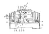
도 3은 본 발명의 일 실시예에 따른 접점 상태 표시 장치가 구비된 차단기의 내부사시도이다.
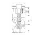
도 4는 본 발명의 일 실시예에 따른 차단기의 접점 상태 표시 장치의 상세도이다.
도 5는 본 발명의 일 실시예에 따른 차단기의 접점 상태 표시 장치에 적용되는 샤프트의 정면도이다.
도 6은 본 발명의 일 실시예에 따른 차단기의 접점 상태 표시 장치의 작용도로서 차단기가 Off상태인 경우를 나타내고 있다.
도 7은 본 발명의 일 실시예에 따른 차단기의 접점 상태 표시 장치의 작용도로서 차단기가 On상태인 경우를 나타내고 있다.
도 8은 본 발명의 일 실시예에 따른 차단기의 접점 상태 표시 장치의 작용도로서 차단기가 Off상태에서 접점부가 융착된 경우를 나타내고 있다.
도 9는 본 발명의 다른 실시예에 따른 차단기의 접점 표시장치가 도시되어 있다.1 is a perspective view showing a state where a cover is removed from a short-circuiting vehicle according to the prior art.
Fig. 2 is a side view of the off state in Fig. 1, showing a state in which the contact portions are fused.
3 is an internal perspective view of a circuit breaker having a contact state display device according to an embodiment of the present invention.
4 is a detailed view of a contact state display apparatus of a circuit breaker according to an embodiment of the present invention.
5 is a front view of a shaft applied to a contact state display apparatus of a circuit breaker according to an embodiment of the present invention.
6 is a functional diagram of a contact state display apparatus for a circuit breaker according to an embodiment of the present invention, in which the circuit breaker is in an off state.
7 is a functional diagram of a contact state display apparatus for a circuit breaker according to an embodiment of the present invention, in which the circuit breaker is in an On state.
FIG. 8 is a functional diagram of a contact state display apparatus of a circuit breaker according to an embodiment of the present invention, in which a contact portion is fused when the circuit breaker is in an off state.
9 is a view showing a contact indicator of a circuit breaker according to another embodiment of the present invention.
이하, 본 발명의 바람직한 실시예를 첨부도면을 참조하여 설명하되, 이는 본 발명이 속하는 기술분야에서 통상의 지식을 가진 자가 발명을 용이하게 실시할 수 있을 정도로 상세하게 설명하기 위한 것이지, 이로 인해 본 발명의 기술적인 사상 및 범주가 한정되는 것을 의미하지는 않는 것이다.
DETAILED DESCRIPTION OF THE PREFERRED EMBODIMENTS Hereinafter, preferred embodiments of the present invention will be described with reference to the accompanying drawings, which are intended to illustrate the present invention in a manner that allows a person skilled in the art to easily carry out the invention. And does not mean that the technical idea and scope of the invention are limited.
도 3은 본 발명의 일 실시예에 따른 접점 상태 표시 장치가 구비된 차단기의 내부사시도이고, 도 4는 본 발명의 일 실시예에 따른 차단기의 접점 상태 표시 장치의 상세도이며, 도 5는 본 발명의 일 실시예에 따른 차단기의 접점 상태 표시 장치에 적용되는 샤프트의 정면도이다. 도면을 참조하여 본 발명의 각 실시예에 따른 에 대하여 상세히 설명하기로 한다.FIG. 3 is an internal perspective view of a circuit breaker provided with a contact state display device according to an embodiment of the present invention, FIG. 4 is a detailed view of a contact state display device of a circuit breaker according to an embodiment of the present invention, 1 is a front view of a shaft applied to a contact state indicator of a circuit breaker according to an embodiment of the present invention. Hereinafter, embodiments of the present invention will be described in detail with reference to the drawings.
본 발명의 일 실시예에 따른 차단기의 접점 상태 표시 장치는 케이스(20); 상기 케이스(20)의 상부에 설치되는 커버(25); 상기 케이스(20)의 일측에 설치되는 고정접촉자(40); 크로스바(50)에 의해 상기 고정접촉자(40)에 접촉 또는 분리될 수 있는 가동접촉자(42); 상기 커버(25)의 일부에 형성되며, 수용부(27)를 갖고, 하면에는 삽입홈(28)이 형성되는 샤프트 삽입구(26); 상기 사프트 삽입구(26)에 상하이동이 가능하도록 삽입되는 샤프트(30); 및 상기 샤프트(30)를 감싸며, 상단은 상기 샤프트 삽입구(26)의 하단부에 접하고, 하단은 상기 샤프트(30)보다 하부로 소정길이 연장 형성되는 압축스프링(36);을 포함하되, 차단기의 Off 상태에서 상기 압축스프링(36)의 하단은 상기 크로스바(50)의 상면에 접하는 것을 특징으로 한다.
A contact state display apparatus of a circuit breaker according to an embodiment of the present invention includes a case (20); A
차단기의 부품을 내장하고 외형을 형성하도록 케이스(20)와 커버(25)가 마련된다.The
케이스(20)의 내부에는 통전부가 마련된다. 세부적으로, 케이스(20)의 양측에는 단자부(21,22)가 마련된다. 일측 단자부(21)는 전원측에 연결되고, 타측 단자부(22)는 부하측에 연결된다. 일측 단자부(21)에는 고정접촉자(40)가 결합된다. 타측 단자부(22)에는 가동접촉자(42)가 연결된다.A power supply portion is provided inside the
케이스(20)의 상부에는 상기 가동접촉자(42)를 움직이도록 하는 기구부가 마련된다. 기구부의 구성과 작동원리는 종래기술과 같으므로 상세한 설명은 생략하기로 한다. 기구부 중에서 가동접촉자(42)에 직접 접촉하여 가동접촉자(42)를 구동시키는 부품은 크로스바(50)이다.On the upper portion of the
케이스(20)의 상면에는 일부에 샤프트 삽입구(26)가 형성된다. 샤프트 삽입구(26)는 케이스(20)의 상면 일부가 내측으로 오목하게 압출되어 형성될 수 있다. 샤프트 삽입구(26)는 원통 형태로 형성될 수 있으며, 내부에 수용부(27)가 형성된다. 이 수용부(27)는 후술하는 샤프트(30)가 삽입될 수 있는 공간이다. 샤프트 삽입구(26)의 하면에는 삽입홈(28)이 형성된다.A
샤프트(30)는 봉 또는 관으로 길게 형성되는 몸체부(32), 상기 몸체부(32)의 상부에 돌출 형성되는 머리부(31), 몸체부(32)의 하부에 형성되는 돌기부(33)로 구성된다.The
몸체부(32)와 돌기부(33)는 샤프트 삽입구(26)의 삽입홈(28)에 삽입되어 상하로 슬라이딩 운동을 하게 된다. 머리부(31)는 샤프트 삽입구(26)의 하단면에 걸리도록 삽입홈(28)의 직경보다 크게 형성된다. 돌기부(33)의 상면은 삽입홈(28)의 직경보다는 작게 형성되지만 몸체부(32)의 직경보다는 크게 형성된다.The
몸체부(32)와 돌기부(33) 사이에는 둘레홈(34)이 형성될 수 있다. 둘레홈(34)에는 후술하는 압축스프링(36)의 중간부가 걸릴 수 있게 된다. 또한, 샤프트(30)의 종축을 따라 몸체부(32)의 하부로부터 돌기부(33)의 하단까지 이르는 분할홈(35)이 형성될 수 있다. 분할홈(35)에 의해 샤프트(30)가 삽입홈(28)에 끼워질 때 돌기부(33)가 오무라들어 용이하게 삽입될 수 있는 효과가 있다. 이 경우, 돌기부(33) 상부의 직경이 삽입홈(28)의 직경보다 약간 크게 형성될 수 있다는 이점도 있다.A
압축스프링(36)은 샤프트(30)에 끼워진다. 압축스프링(36)은 중간의 걸림부(36c)를 경계로 하여 상부스프링부(36a)와 하부스프링부(36b)로 나누어진다. 상부스프링부(36a)부는 일정한 직경으로 형성되며, 하부스프링부(36b)는 원추형 직경으로 형성될 수 있다. 걸림부(36c)는 돌기부(33)의 상면에 얹히거나 둘레홈(34)에 걸리도록 설치된다.The
압축스프링(36)의 상단부가 샤프트 삽입구(26)의 하면에 걸리고, 걸림부(36c)가 둘레홈(34)에 고정된다. 이때, 하부스프링부(36b)는 돌기부(33)의 하방으로 연장 형성되어 자유로운 상태에 있게 된다.The upper end of the
다른 실시예로 압축스프링(36)은 두 개의 스프링으로 나누어져 구성될 수 있다. 즉, 상부스프링부(36a)는 제1스프링, 하부스프링부(36b)는 제2스프링으로 나누어져 구성될 수 있다. 이 경우에는 기성제품을 활용할 수 있으므로, 제작 및 적용이 용이하게 될 수 있는 장점이 있다. 제1스프링을 샤프트 삽입구(26)의 하면과 둘레홈(34) 사이에 끼워 설치하고, 제2스프링을 둘레홈(34)에 끼워 매다는 상태로 설치할 수 있다.
In another embodiment, the
본 발명의 일 실시예에 따른 차단기의 접점 상태 표시 장치의 작용을 설명하기로 한다.The operation of the contact state display apparatus of the circuit breaker according to the embodiment of the present invention will be described.
도 6에는 차단기가 Off상태인 경우가 도시되어 있다. 핸들(29)이 Off위치(도면상 오른쪽)에 놓여 있다. 가동접촉자(42)는 고정접촉자(40)로부터 분리되어 이격된 상태에 놓여 있으며, 크로스바(50)는 상승위치에 놓여있다. 압축스프링(36)의 하단이 크로스바(50)의 상면에 접촉하여 탄성력을 받으므로 샤프트(30)는 상승한 위치, 즉, 머리부(31)가 커버(25)의 상부로 돌출된 상태에 놓여있게 된다. 이때, 만약 사용자가 실수로 샤프트(30)의 머리부(31)를 누르는 경우에는 하부스프링부(36b)가 압축되면서 힘이 저장되므로 크로스바(50)를 누르지 않게 된다.6 shows a case where the circuit breaker is in the OFF state. The
도 7에는 차단기가 On상태인 경우가 도시되어 있다. 핸들(29)이 On위치(도면상 왼쪽)에 놓여 있다. 크로스바(50)가 하강위치에 있게 된다. 가동접촉자(42)는 크로스바(50)의 힘을 받아 고정접촉자(40)에 접촉한 상태에 있게 된다. 압축스프링(36)은 크로스바(50)로부터 분리되어 크로스바(50)에 의한 힘을 받지 않으므로 상부스프링부(36a)의 복원력이 작용하여 샤프트(30)는 하강 위치에 놓이게 된다. 따라서, 머리부(31)는 커버(25)의 상부로 돌출하지 않게 된다.Fig. 7 shows a case where the circuit breaker is in the On state. The
도 8은 차단기가 Off상태에서 접점부가 융착된 경우를 나타내고 있다. 핸들(29)이 Off위치에 놓여 있다. 차단기가 Off상태임에도 불구하고 가동접촉자(42)와 고정접촉자(40)가 융착 등에 의해 떨어지지 않고 접촉되어 있는 상태에 놓여있다. 이 경우에는 샤프트(30)가 하강 위치에 놓여 있으므로 머리부(31)는 커버(25)의 상부로 돌출하지 않게 된다. 따라서, 시각적으로 바로 접점부의 미분리 상태를 알 수 있게 된다.8 shows a case where the contact portion is fusion-bonded while the circuit breaker is in the off state. The
본 발명의 일 실시예에 따른 차단기의 접점 표시장치에 의하면 사용자는 핸들(29)의 오프 상태 뿐 아니라 접점부의 오프 상태까지 확인할 수 있으므로 안전하게 작업을 수행할 수 있게 된다.
According to the contact point display apparatus of the circuit breaker according to the embodiment of the present invention, since the user can confirm not only the off state of the
도 9에는 본 발명의 다른 실시예에 따른 차단기의 접점 표시장치가 도시되어 있다. 구성과 작동은 전 실시예와 동일하되 샤프트 삽입구(26)가 커버(25)의 상부로 연장되어 머리부(31) 주변을 감싸는 둘레면(26a)을 형성하는 점이 특징이다. 둘레면(26a)이 형성되어 있으므로 사용자가 실수로 샤프트(30)를 누르게 될 염려가 사라진다.
FIG. 9 shows a contact indicator of a circuit breaker according to another embodiment of the present invention. The structure and operation are the same as those of the previous embodiment except that the
비록 본 발명이 상기 언급된 바람직한 실시 예와 관련하여 설명되어졌지만, 발명의 요지와 범위로부터 벗어남이 없이 다양한 수정 및 변형이 가능한 것은 당업자라면 용이하게 인식할 수 있을 것이며, 이러한 변경 및 수정은 모두 첨부된 청구의 범위에 속함은 자명하다.
Although the present invention has been described in connection with the above-mentioned preferred embodiments, it will be apparent to those skilled in the art that various modifications and variations can be made without departing from the spirit and scope of the invention, It is obvious that the claims fall within the scope of the claims.
20 케이스21 일측 단자부
22 타측 단자부25 커버
26 샤프트 삽입구27 수용부
28 삽입홈29 핸들
30 샤프트31 머리부
32 몸체부33 돌기부
34 둘레홈35 분할홈
36 압축스프링36a 상부스프링부
36b 하부스프링부36c 걸림부
40 고정접촉자42 가동접촉자
50 크로스바20
22
26
28
30
32
34
36
36b
40
50 crossbars
Claims (8)
Translated fromKorean상기 케이스의 상부에 설치되는 커버;
상기 케이스의 일측에 설치되는 고정접촉자;
크로스바에 의해 상기 고정접촉자에 접촉 또는 분리될 수 있는 가동접촉자;
상기 커버의 일부에 형성되며, 수용부를 갖고, 하면에는 삽입홈이 형성되는 샤프트 삽입구;
상기 사프트 삽입구에 상하이동이 가능하도록 삽입되는 샤프트; 및
상기 샤프트를 감싸며, 상단은 상기 샤프트 삽입구의 하단부에 접하고, 하단은 상기 샤프트보다 하부로 소정길이 연장 형성되는 압축스프링;을 포함하되,
차단기의 Off 상태에서 상기 압축스프링의 하단은 상기 크로스바의 상면에 접하는 것을 특징으로 하는 차단기의 접점 상태 표시 장치.
case;
A cover provided on an upper portion of the case;
A fixed contact installed on one side of the case;
A movable contact which can be brought into contact with or separated from the fixed contact by a crossbar;
A shaft insertion port formed in a part of the cover, the shaft insertion port having a receiving portion and an insertion groove formed in a lower surface;
A shaft inserted into the shaft insertion hole so as to be vertically movable; And
And a compression spring which surrounds the shaft and has an upper end contacting with a lower end of the shaft insertion port and a lower end extending downward from the shaft by a predetermined length,
And the lower end of the compression spring is in contact with the upper surface of the crossbar in the OFF state of the breaker.
2. The circuit breaker according to claim 1, wherein the shaft includes a body portion formed of a rod or a tube, a head portion protruding from an upper portion of the body portion, and a protrusion portion protruding from a lower portion of the body portion. Device.
3. The apparatus according to claim 2, wherein a circumferential groove is formed between the body and the protrusion.
3. The apparatus according to claim 2, wherein the shaft is formed with a dividing groove extending from a lower portion of the body portion to a lower end of the protrusion portion.
3. The apparatus according to claim 2, wherein the diameter of the head portion is larger than the diameter of the insertion groove.
상단이 상기 샤프트 삽입구의 하단부에 접하고, 하단은 상기 둘레홈에 끼워지는 제1스프링; 및
상단이 상기 둘레홈에 끼워지고 하단은 상기 샤프트보다 하부로 소정길이 연장 형성되는 제2스프링;으로 구성되는 것을 특징으로 하는 차단기의 접점 상태 표시 장치.
3. The apparatus according to claim 2,
A first spring having an upper end abutting against a lower end of the shaft insertion port and a lower end fitted into the peripheral groove; And
And a second spring having an upper end fitted in the peripheral groove and a lower end extending downwardly from the shaft by a predetermined length.
The apparatus of claim 1, wherein the compression spring separates from the crossbar when the breaker is on.
Priority Applications (1)
| Application Number | Priority Date | Filing Date | Title |
|---|---|---|---|
| KR1020140101838AKR101777614B1 (en) | 2014-08-07 | 2014-08-07 | Contact Status Indicator of Circuit Breaker |
Applications Claiming Priority (1)
| Application Number | Priority Date | Filing Date | Title |
|---|---|---|---|
| KR1020140101838AKR101777614B1 (en) | 2014-08-07 | 2014-08-07 | Contact Status Indicator of Circuit Breaker |
Publications (2)
| Publication Number | Publication Date |
|---|---|
| KR20160018005Atrue KR20160018005A (en) | 2016-02-17 |
| KR101777614B1 KR101777614B1 (en) | 2017-09-13 |
Family
ID=55457336
Family Applications (1)
| Application Number | Title | Priority Date | Filing Date |
|---|---|---|---|
| KR1020140101838AActiveKR101777614B1 (en) | 2014-08-07 | 2014-08-07 | Contact Status Indicator of Circuit Breaker |
Country Status (1)
| Country | Link |
|---|---|
| KR (1) | KR101777614B1 (en) |
Cited By (3)
| Publication number | Priority date | Publication date | Assignee | Title |
|---|---|---|---|---|
| KR20180105974A (en)* | 2017-03-16 | 2018-10-01 | 엘에스산전 주식회사 | Circuit breaker |
| KR20190017368A (en)* | 2017-08-11 | 2019-02-20 | 엘에스산전 주식회사 | Circuit protector |
| EP3594986A1 (en)* | 2018-07-10 | 2020-01-15 | LSIS Co., Ltd. | Switching mechanism of circuit breaker |
Families Citing this family (1)
| Publication number | Priority date | Publication date | Assignee | Title |
|---|---|---|---|---|
| KR102249812B1 (en)* | 2019-02-14 | 2021-05-10 | 엘에스일렉트릭(주) | Small circuit breaker |
- 2014
- 2014-08-07KRKR1020140101838Apatent/KR101777614B1/enactiveActive
Cited By (4)
| Publication number | Priority date | Publication date | Assignee | Title |
|---|---|---|---|---|
| KR20180105974A (en)* | 2017-03-16 | 2018-10-01 | 엘에스산전 주식회사 | Circuit breaker |
| KR20190017368A (en)* | 2017-08-11 | 2019-02-20 | 엘에스산전 주식회사 | Circuit protector |
| EP3594986A1 (en)* | 2018-07-10 | 2020-01-15 | LSIS Co., Ltd. | Switching mechanism of circuit breaker |
| US10811209B2 (en) | 2018-07-10 | 2020-10-20 | Lsis Co., Ltd. | Switching mechanism of circuit breaker |
Also Published As
| Publication number | Publication date |
|---|---|
| KR101777614B1 (en) | 2017-09-13 |
Similar Documents
| Publication | Publication Date | Title |
|---|---|---|
| KR100876535B1 (en) | Auxiliary contact device of breaker | |
| ES2527571T3 (en) | Modules and disconnecting devices fuse switches with multifunctional trip mechanism | |
| US9224548B2 (en) | Disconnect switch including fusible switching disconnect modules | |
| KR101777614B1 (en) | Contact Status Indicator of Circuit Breaker | |
| EP3161848B1 (en) | High current, compact fusible disconnect switch with dual slider bar actuator assembly | |
| ES2592697T3 (en) | Modules and disconnector switch devices with fuse with in-line current detection | |
| EP2492944A2 (en) | Circuit breaker | |
| ES2527593T3 (en) | Modules and disconnecting devices fuse switches electronically controlled | |
| EP3343710B1 (en) | Position indicator of air circuit breaker | |
| KR102524504B1 (en) | Switching Mechanism of Circuit Breaker | |
| KR101728759B1 (en) | Miniature circuit breaker equipped with over current protection button | |
| KR100914204B1 (en) | Wiring breakers with contact-on appliances | |
| CN109243929B (en) | A molded case circuit breaker with adjustable overload alarm and non-tripping function | |
| KR100885849B1 (en) | Circuit breaker with contact on mechanism | |
| KR101537679B1 (en) | Device for displaying of contact in circuit breaker | |
| CN109659207B (en) | Resistance abrupt contact device and circuit breaker | |
| KR20130000092U (en) | A magnetic contactor | |
| KR101264565B1 (en) | Surge protector apparatus having one piece overheat protection and moment cutoff function based on surge suppression device | |
| KR101734229B1 (en) | Detecting unit for trip driving of circuit breaker | |
| KR101759596B1 (en) | Switching Mechanism of Miniature Circuit Breaker | |
| CN223427439U (en) | Circuit breakers and electrical control cabinets | |
| KR20160090687A (en) | Structure of Crossbar for Manual Motor Starter | |
| CN109616391B (en) | Resistance-variable contact mechanism and arc-proof circuit breaker | |
| CN216054533U (en) | Circuit breaker | |
| KR200411518Y1 (en) | Contact status display device of circuit breaker |
Legal Events
| Date | Code | Title | Description |
|---|---|---|---|
| PA0109 | Patent application | Patent event code:PA01091R01D Comment text:Patent Application Patent event date:20140807 | |
| PG1501 | Laying open of application | ||
| PA0201 | Request for examination | Patent event code:PA02012R01D Patent event date:20161014 Comment text:Request for Examination of Application Patent event code:PA02011R01I Patent event date:20140807 Comment text:Patent Application | |
| E902 | Notification of reason for refusal | ||
| PE0902 | Notice of grounds for rejection | Comment text:Notification of reason for refusal Patent event date:20170209 Patent event code:PE09021S01D | |
| E701 | Decision to grant or registration of patent right | ||
| PE0701 | Decision of registration | Patent event code:PE07011S01D Comment text:Decision to Grant Registration Patent event date:20170817 | |
| GRNT | Written decision to grant | ||
| PR0701 | Registration of establishment | Comment text:Registration of Establishment Patent event date:20170906 Patent event code:PR07011E01D | |
| PR1002 | Payment of registration fee | Payment date:20170907 End annual number:3 Start annual number:1 | |
| PG1601 | Publication of registration | ||
| PR1001 | Payment of annual fee | Payment date:20200701 Start annual number:4 End annual number:4 | |
| PR1001 | Payment of annual fee | Payment date:20210712 Start annual number:5 End annual number:5 | |
| PR1001 | Payment of annual fee | Payment date:20220622 Start annual number:6 End annual number:6 | |
| PR1001 | Payment of annual fee | Payment date:20230627 Start annual number:7 End annual number:7 | |
| PR1001 | Payment of annual fee | Payment date:20240624 Start annual number:8 End annual number:8 | |
| PR1001 | Payment of annual fee | Payment date:20250624 Start annual number:9 End annual number:9 |