KR20160017138A - Method for controlling a headlight assembly for a vehicle and headlight assembly therefor - Google Patents
Method for controlling a headlight assembly for a vehicle and headlight assembly thereforDownload PDFInfo
- Publication number
- KR20160017138A KR20160017138AKR1020167002751AKR20167002751AKR20160017138AKR 20160017138 AKR20160017138 AKR 20160017138AKR 1020167002751 AKR1020167002751 AKR 1020167002751AKR 20167002751 AKR20167002751 AKR 20167002751AKR 20160017138 AKR20160017138 AKR 20160017138A
- Authority
- KR
- South Korea
- Prior art keywords
- headlight
- vehicle
- optical axes
- headlamp
- assembly
- Prior art date
- Legal status (The legal status is an assumption and is not a legal conclusion. Google has not performed a legal analysis and makes no representation as to the accuracy of the status listed.)
- Ceased
Links
Images


Classifications
- B—PERFORMING OPERATIONS; TRANSPORTING
- B60—VEHICLES IN GENERAL
- B60Q—ARRANGEMENT OF SIGNALLING OR LIGHTING DEVICES, THE MOUNTING OR SUPPORTING THEREOF OR CIRCUITS THEREFOR, FOR VEHICLES IN GENERAL
- B60Q1/00—Arrangement of optical signalling or lighting devices, the mounting or supporting thereof or circuits therefor
- B60Q1/02—Arrangement of optical signalling or lighting devices, the mounting or supporting thereof or circuits therefor the devices being primarily intended to illuminate the way ahead or to illuminate other areas of way or environments
- B60Q1/04—Arrangement of optical signalling or lighting devices, the mounting or supporting thereof or circuits therefor the devices being primarily intended to illuminate the way ahead or to illuminate other areas of way or environments the devices being headlights
- B60Q1/14—Arrangement of optical signalling or lighting devices, the mounting or supporting thereof or circuits therefor the devices being primarily intended to illuminate the way ahead or to illuminate other areas of way or environments the devices being headlights having dimming means
- B60Q1/1415—Dimming circuits
- B60Q1/1423—Automatic dimming circuits, i.e. switching between high beam and low beam due to change of ambient light or light level in road traffic
- B—PERFORMING OPERATIONS; TRANSPORTING
- B60—VEHICLES IN GENERAL
- B60Q—ARRANGEMENT OF SIGNALLING OR LIGHTING DEVICES, THE MOUNTING OR SUPPORTING THEREOF OR CIRCUITS THEREFOR, FOR VEHICLES IN GENERAL
- B60Q1/00—Arrangement of optical signalling or lighting devices, the mounting or supporting thereof or circuits therefor
- B60Q1/02—Arrangement of optical signalling or lighting devices, the mounting or supporting thereof or circuits therefor the devices being primarily intended to illuminate the way ahead or to illuminate other areas of way or environments
- B60Q1/04—Arrangement of optical signalling or lighting devices, the mounting or supporting thereof or circuits therefor the devices being primarily intended to illuminate the way ahead or to illuminate other areas of way or environments the devices being headlights
- B60Q1/06—Arrangement of optical signalling or lighting devices, the mounting or supporting thereof or circuits therefor the devices being primarily intended to illuminate the way ahead or to illuminate other areas of way or environments the devices being headlights adjustable, e.g. remotely-controlled from inside vehicle
- B60Q1/08—Arrangement of optical signalling or lighting devices, the mounting or supporting thereof or circuits therefor the devices being primarily intended to illuminate the way ahead or to illuminate other areas of way or environments the devices being headlights adjustable, e.g. remotely-controlled from inside vehicle automatically
- F—MECHANICAL ENGINEERING; LIGHTING; HEATING; WEAPONS; BLASTING
- F21—LIGHTING
- F21S—NON-PORTABLE LIGHTING DEVICES; SYSTEMS THEREOF; VEHICLE LIGHTING DEVICES SPECIALLY ADAPTED FOR VEHICLE EXTERIORS
- F21S41/00—Illuminating devices specially adapted for vehicle exteriors, e.g. headlamps
- B—PERFORMING OPERATIONS; TRANSPORTING
- B60—VEHICLES IN GENERAL
- B60Q—ARRANGEMENT OF SIGNALLING OR LIGHTING DEVICES, THE MOUNTING OR SUPPORTING THEREOF OR CIRCUITS THEREFOR, FOR VEHICLES IN GENERAL
- B60Q2300/00—Indexing codes for automatically adjustable headlamps or automatically dimmable headlamps
- B60Q2300/05—Special features for controlling or switching of the light beam
- B60Q2300/056—Special anti-blinding beams, e.g. a standard beam is chopped or moved in order not to blind
- B—PERFORMING OPERATIONS; TRANSPORTING
- B60—VEHICLES IN GENERAL
- B60Q—ARRANGEMENT OF SIGNALLING OR LIGHTING DEVICES, THE MOUNTING OR SUPPORTING THEREOF OR CIRCUITS THEREFOR, FOR VEHICLES IN GENERAL
- B60Q2300/00—Indexing codes for automatically adjustable headlamps or automatically dimmable headlamps
- B60Q2300/40—Indexing codes relating to other road users or special conditions
- B60Q2300/45—Special conditions, e.g. pedestrians, road signs or potential dangers
Landscapes
- Engineering & Computer Science (AREA)
- Mechanical Engineering (AREA)
- General Engineering & Computer Science (AREA)
- Lighting Device Outwards From Vehicle And Optical Signal (AREA)
Abstract
Translated fromKoreanDescription
Translated fromKorean본 발명은 우측 전조등 유닛과 좌측 전조등 유닛을 구비하는 차량용 전조등 어셈블리를 제어하는 방법으로서, 하향등 기능(dipped-beam function)을 위해 전조등 유닛들의 광축들을 평행한 정렬에 대해 수평으로 서로 발산하게 선회시키는 차량용 전조등 어셈블리의 제어 방법에 관한 것이다. 또한, 본 발명은 우측 전조등 유닛과 좌측 전조등 유닛 및 적어도 하나의 제어 장치를 구비하고, 하향등 기능을 위해 전조등 유닛들의 광축들이 제어 장치에 의해 평행한 정렬에 대해 수평으로 서로 발산하게 선회할 수 있는 차량용 전조등 어셈블리에 관한 것이기도 하다.A method of controlling a vehicle headlight assembly having a right headlight unit and a left headlight unit, the method comprising: turning the optical axes of the headlight units to diverge horizontally relative to a parallel alignment for a dipped- To a control method of a vehicle headlight assembly. The present invention also relates to a control system for a vehicle having a right-side headlight unit, a left-side headlight unit and at least one control unit, in which the optical axes of the headlight units for the downward light function are swiveled And more particularly to a vehicle headlight assembly.
차량의 전조등 어셈블리는 어두울 때에 차량의 전방의 주행하는 교통 구역을 가능한 한 잘 비추기 위한 목적을 갖는다. 그를 위해, 통상적으로 매우 큰 커버리지 범위를 갖는 광 분포를 제공하는 상향등 기능을 갖는다. 그러나 상향등 기능(main beam function)에서는 다른 통행자, 특히 맞은편에서 오거나 앞서 가는 차량의 운전자가 상향등의 발광에 의해 눈부심을 겪는다는 문제점이 생기게 된다. 그러한 이유로, 전조등 어셈블리에 의해 하향등 기능이 추가로 제공되는 것이 통상적인데, 그러한 하향등 기능의 광 분포도 또한 실제로 차량의 전방의 교통 구역에 대한 가능한 한 포괄적인 조명을 제공하기는 하지만, 그와 동시에 다른 통행자의 눈부심을 유발하지는 않는다.The vehicle's headlight assembly has the purpose of illuminating the running traffic area in front of the vehicle as bright as possible in the dark. For that purpose, it typically has an upward light function that provides a light distribution with a very large coverage range. However, in the main beam function, there arises a problem that the driver of the other passenger, especially the vehicle coming or coming from the opposite side, is glazed by the emission of the upward light. For that reason, it is customary that a downward light function is additionally provided by the headlight assembly, such that the light distribution of the downward light function also actually provides the most comprehensive illumination for the traffic area in front of the vehicle, but at the same time It does not cause glare on other passers-by.
통상적으로, 차량의 운전자는 하향등 기능과 상향등 기능 사이를 수동으로 이쪽저쪽으로 전환한다. 그러나 그것은 운전자의 고도의 집중을 필요로 하고, 다른 안전 관련 정보들에 대한 주의 산만을 유발할 수 있다. 따라서 전조등 어셈블리의 발광의 방향으로 통행자를 검출할 수 있고, 전조등 어셈블리의 전체 광 분포를 검출된 통행자의 위치에 맞춰 그 통행자가 더 이상 눈부시지 않게 조정하는 전조등 어셈블리가 개발되었다. 예컨대, WO 2008/037388 A2에는 검출된 다른 통행자의 눈부심을 방지하기 위한 하향등 기능을 위해 전조등 유닛들의 광선의 방출 방향들을 수평으로 서로 발산하게 선회시키는 차량용 전조등 어셈블리의 제어 방법이 제시되어 있다.Typically, the driver of the vehicle manually switches between the down light function and the up light function. However, it requires a driver's high concentration and can distract attention to other safety-related information. Accordingly, a headlamp assembly has been developed that can detect a passenger in the direction of light emission of the headlamp assembly, and adjust the overall light distribution of the headlamp assembly to the position of the detected passer, so that the passenger is no longer blind. For example, WO 2008/037388 A2 discloses a control method for a vehicular headlamp assembly that swings the emission directions of light beams of headlight units horizontally to each other for a downward light function for preventing glare of other detected passengers.
본 발명의 과제는 차량의 운전자에게 그의 전방에 놓인 차도에 대한 최대한으로 양호한 시야를 제공할 수 있는 동시에, 다른 통행자의 눈부심을 효과적으로 방지할 수 있는 차량용 전조등 어셈블리의 제어 방법 및 그러한 차량용 전조등 어셈블리를 제공하는 것이다.The object of the present invention is to provide a vehicle headlight assembly control method and a vehicle headlight assembly capable of providing the driver of the vehicle with a maximized view of the roadway placed in front of him or her and capable of effectively preventing the glare of other passengers .
그러한 과제는 본 발명에 따라 청구항 1의 특징들을 갖는 방법 및 청구항 8의 특징들을 갖는 전조등 어셈블리에 의해 해결된다. 바람직한 구성들 및 부가의 구성들은 종속 청구항들로부터 명확히 드러나고 있다.Such a problem is solved by a method having the features of
본 발명에 따른 방법에서는, 상향등 기능을 위해 전조등 유닛들의 광축들을 평행한 정렬에 대해 수평으로 서로 수렴하게 선회시킨다. 즉, 전조등의 광축들을 차량의 전방으로 정해진 거리 떨어져 교차시킨다. 광축들이 하향등 기능에 대한 선회 각도에서와 같이 서로 발산하지 않는다.In the method according to the present invention, the optical axes of the headlight units are turned to converge horizontally with respect to the parallel alignment for the upward light function. That is, the optical axes of the headlights are crossed at a predetermined distance forward of the vehicle. The optical axes do not diverge from each other as in the turning angle for the downward light function.
본 발명의 취지에서, 하향등 기능이란 다른 통행자가 눈부심을 당하는 것을 방지하는 광 분포를 의미한다. 여기서, 하향등 기능은 종래의 하향등만을 의미하는 것이 아니라, 다른 통행자의 눈부심이 방지되도록 그 광 분포가 변경되는 종래의 상향등도 의미하는 것이다. 그러한 하향등 기능은 예컨대 적응적 상향등(adpative high beam light) 또는 마스킹된 상향등(masked high beam light)으로도 지칭된다. 본 발명의 취지에서, 상향등 기능이란 혹시 있을 수 있는 다른 통행자의 눈부심을 고려함이 없이 차량의 전방의 주위를 최대로 비추는 것을 지향하는 광 분포를 의미한다.For purposes of the present invention, the downward light function means a light distribution that prevents other passersby from being glare. Here, the downward light function does not mean only conventional downward light, but also means a conventional upward light whose light distribution is changed so as to prevent glare of other passers. Such a downward beam function is also referred to as an adipative high beam light or a masked high beam light. In the context of the present invention, the upward light function means a light distribution that tends to maximize the circumference of the front of the vehicle without considering the possible glare of other passengers.
전조등 유닛들의 광축들은 전조등 유닛들의 주 발광 방향으로부터 주어진다. 또한, 전조등 유닛 그 자체의 기하 형태로부터 주어질 수 있다. 전조등 유닛들로부터 평행 광선이 방출되면, 광축은 그 광선과 평행하고 전조등 유닛의 광원을 통과한다. 전조등 유닛이 다수의 광원들을 포함하면, 광축은 예컨대 전조등 유닛의 중심을 통해 연장되고, 전조등 유닛으로부터 방출되는 광선과 평행하게 정렬된다. 또한, 광축은 전조등 유닛의 최대 조도의 방향일 수 있다. 예컨대, 최대의 조도는 전조등 유닛의 전방으로 예컨대 10 m 간격을 두고 전조등 유닛의 발광 방향에 수직으로 배치되는 측정 스크린에 의해 산출될 수 있다.The optical axes of the headlight units are given from the main emission direction of the headlight units. Also, it can be given from the geometric shape of the headlight unit itself. When a parallel light beam is emitted from the headlight units, the optical axis is parallel to the light beam and passes through the light source of the headlight unit. If the headlight unit includes a plurality of light sources, the optical axis extends, for example, through the center of the headlight unit and aligned parallel to the light rays emitted from the headlight unit. Further, the optical axis may be the direction of the maximum illuminance of the headlamp unit. For example, the maximum illuminance can be calculated by a measurement screen which is disposed perpendicularly to the light emitting direction of the headlight unit, for example, at intervals of 10 m toward the front of the headlight unit.
본 발명에 따른 방법의 구성에 따르면, 전조등 어셈블리의 발광의 방향으로 통행자를 검출하고, 하향등 기능을 위해 전조등 어셈블리에 의해 생성되는 광 분포를 차량에 대한 통행자의 위치에 의존하여 제어한다. 특히, 하향등 기능을 위해 전조등 어셈블리에 의해 생성되는 광 분포를, 검출된 통행자의 방향으로 더 적은 전조등 범위(headlight range)를 갖는 중앙 영역 및 이 중앙 영역의 양옆으로 더 큰 전조등 범위를 갖는 측방 영역들이 생성되도록 변경한다. 또한, 전조등 어셈블리의 발광의 방향으로 전조등 어셈블리에 대해 수직으로 통행자의 각도를 검출할 수 있다. 그 경우에도 또한 하향등 기능을 위해 통행자의 방향으로의 전조등 범위를 통행자의 수직 각도에 의존하여 제어할 수 있다.According to the configuration of the method according to the present invention, the passenger is detected in the direction of the light emission of the headlight assembly, and the light distribution generated by the headlight assembly for the downward light function is controlled depending on the position of the passenger for the vehicle. In particular, the light distribution produced by the headlamp assembly for the downward light function can be reduced by a central region having a smaller headlight range in the direction of the detected passer and a lateral region having a larger headlight range on either side of the central region Are generated. Further, the angle of the passenger can be detected perpendicular to the headlight assembly in the direction of the light emission of the headlight assembly. In that case, too, the range of headlights in the direction of the passenger can be controlled depending on the vertical angle of the passenger for the downward light function.
본 발명에 따른 방법의 구성에 따르면, 상향등 기능을 위해 전조등 유닛들의 광축들을 수평 정렬에 대해 수직으로 아래쪽으로 선회시킨다.According to the configuration of the method according to the present invention, the optical axes of the headlamp units are turned downward perpendicularly to the horizontal alignment for the upward light function.
상향등 기능을 위해, 전조등 유닛들의 광축들을 특히 차량의 전방으로 정해진 거리 떨어져 전조등 유닛들 사이의 중앙에서 그 광축들이 교차하도록 선회시킨다. 그러한 광축들의 교차점은 예컨대 차량의 전방으로 200 m 내지 500 m의 범위에 있다. 교차점은 특히 차도 상에 놓이거나, 타이어와 차도의 접촉점으로부터 펼쳐지는 평면 상에 놓인다.For the upward light function, the optical axes of the headlight units are swiveled so that their optical axes intersect, particularly at the center between the headlight units, at a predetermined distance forward of the vehicle. The intersection of such optical axes is for example in the range of 200 m to 500 m in front of the vehicle. The intersection is placed on the driveway, or on a plane that extends from the contact point of the tire and the roadway.
본 발명에 따른 방법에 의해, 한편으로 다른 통행자의 눈부심을 방지할 수 있는 하향등 기능이 제공되게 된다. 다른 한편으로, 차량의 전방의 교통 영역을 최적으로 비추는 상향등 기능이 제공되게 된다. 여기서, 본 발명에 따른 상향등 기능은 전조등 유닛들이 평행한 정렬에 대해 수평으로 서로 수렴하게 선회하고 광축들의 교차점이 차량의 전방으로 전조등 유닛들 사이의 중앙에 주어진다는 점에서 종래의 상향등 기능과 차이가 있다.With the method according to the invention, a downward light function is provided which on the one hand can prevent the glare of other passers. On the other hand, an upward light function that optimizes the traffic area in front of the vehicle is provided. Here, the upward light function according to the present invention differs from the conventional upright function in that the headlight units are swiveled to converge horizontally with respect to each other in parallel alignment and the intersection of the optical axes is given to the center between the headlight units in front of the vehicle have.
본 발명에 따른 전조등 어셈블리는 상향등 기능을 위해 전조등 유닛들의 광축들이 제어 장치에 의해 평행한 정렬에 대해 수평으로 서로 수렴하게 선회할 수 있는 것을 특징으로 한다.The headlamp assembly according to the present invention is characterized in that the optical axes of the headlamp units can be swiveled to converge horizontally with respect to the parallel alignment by the control device for the upward light function.
본 발명에 따른 전조등 유닛의 부가의 구성에 따르면, 전조등 어셈블리는 전조등 어셈블리의 발광의 방향으로 다른 통행자를 검출하는 장치와 결합된다. 그 경우, 광 분포는 차량에 대한 다른 통행자의 위치에 의존하여 제어 장치에 의해 제어될 수 있다.According to an additional configuration of the headlamp unit according to the present invention, the headlamp assembly is combined with a device for detecting another passenger in the direction of light emission of the headlamp assembly. In that case, the light distribution can be controlled by the control device depending on the position of the other passenger relative to the vehicle.
또한, 전조등 어셈블리는 특히 상향등 기능을 위한 전조등 유닛들의 광축들의 선회 각도에 대한 파라미터들이 저장되어 있는 메모리를 포함한다. 메모리에 저장된 파라미터들은 하향등 기능으로부터 상향등 기능으로 전환할 경우에 하향등 기능의 광축들의 수평 및 수직 정렬을 상향등 기능에 맞춰 조정하는데 사용된다. 그와 같이 하여, 좌측과 우측 전조등 유닛들의 발광의 중첩으로부터 주어지는 최적의 광 분포가 제공되게 된다.The headlight assembly also includes a memory in which parameters for the angle of rotation of the optical axes of the headlight units for the upward light function are stored. The parameters stored in the memory are used to adjust the horizontal and vertical alignment of the optical axes of the downward light function to the upward light function when switching from the down light function to the upward light function. In this way, the optimum light distribution given from the superposition of the light emission of the left and right headlight units is provided.
광축들을 상향등 기능에 맞춰 조정하는 기능을 위해, 별개의 제어 장치가 마련될 수도 있다. 또한, 그러한 조정은 소프트웨어 모듈에 의해 전조등 유닛(들)에 대한 제어 장치 또는 제어 장치들에 통합될 수 있다.For the function of adjusting the optical axes to the upward light function, a separate control device may be provided. Further, such adjustment may be incorporated into the control device or control devices for the headlight unit (s) by the software module.
이하, 본 발명을 첨부 도면들을 참조해서 실시예들에 의거하여 더욱 상세히 설명하기로 한다. 첨부 도면들 중에서,
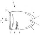
도 1은 본 발명에 따른 전조등 어셈블리의 전조등 유닛의 실시예를 개략적으로 나타낸 도면이고;
도 2는 본 발명에 따른 전조등 어셈블리의 실시예를 개략적으로 나타낸 도면이며,
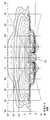
도 3은 앞서 가는 차량의 검출 시에 수직 벽 상에서의 하향등 기능을 위한 전체 광도 분포의 등조도 다이어그램(isolux diagram)을 나타낸 도면이고,
도 4는 앞서 가는 차량이 탐지되었을 때에 하향등 기능을 위한 전조등 유닛들의 광축들의 정렬을 나타낸 도면이며,
도 5는 상향등 기능을 위한 전조등 유닛들의 광축들의 정렬을 나타낸 도면이다.Hereinafter, the present invention will be described in more detail based on embodiments with reference to the accompanying drawings. In the accompanying drawings,
1 is a view schematically showing an embodiment of a headlamp unit of a headlamp assembly according to the present invention;
2 is a view schematically showing an embodiment of a headlamp assembly according to the present invention,
3 is a diagram showing an isolux diagram of the overall luminous intensity distribution for a downward light function on a vertical wall at the time of detection of a preceding vehicle,
4 is a view showing the alignment of the optical axes of the headlamp units for the downward light function when the preceding vehicle is detected,
5 is a view showing the alignment of the optical axes of the headlamp units for the upward light function.
전조등 어셈블리는 차량의 좌측과 우측 전방에 공지의 방식대로 배치되어 전조등 유닛을 각각 형성하는 2개의 이격된 프로젝션 전조등(projection headlight)들(1, 2)을 포함한다. 대안적으로, 전조등 유닛은 다수의 전조등들을 포함할 수 있다. 프로젝션 전조등(1)은 도 1에 도시되어 있다. 다른 측에 배치되는 프로젝션 전조등(2)도 기본적으로 동일하게 구성된다.The headlight assembly includes two spaced
도 1에는, 차량의 길이 방향 축과 수직선(V)으로부터 펼쳐지는 평면과 평행한 평면에서의 단면이 도시되어 있다. 프로젝션 전조등(1)은 공지의 방식대로 회전 타원체로서 형성된 반사판(6)에 의해 둘러싸이는 광원(3)을 포함한다. 즉, 반사판(6)은 2개의 초점을 갖는다. 광원(3)은 반사판(3)의 초점 중 하나에 위치한다. 광원(3)으로부터 발광하는 빛은 반사판(6)으로부터 프로젝션 전조등(1)의 발광 방향(L1)으로 프로젝션 렌즈(7) 쪽으로 반사된다. 발광 방향(L1)은 프로젝션 전조등의 광축이기도 하다. 2차원 형상의 조리개(aperture)(8, 9)을 갖는 조리개 장치가 반사판(6)의 제2 초점의 부근에서 프로젝션 렌즈(7)의 초점에 배치된다. 2차원 형상의 조리개들(8, 9)의 법선들은 발광 방향(L1)과 거의 평행하게 정렬된다. 광원(3), 반사판(6), 렌즈(7), 및 조리개들(8, 9)은 글라스 패널(5)에 의해 밀폐되는 하우징(4) 내에 배치된다.Figure 1 shows a section in a plane parallel to the plane extending from the longitudinal axis of the vehicle and the vertical axis (V). The
프로젝션 전조등(1)은 대체로 공지의 방식대로 전조등 범위의 조절을 위해 화살표(A)의 방향으로 위아래로 선회될 수 있다. 즉, 프로젝션 전조등(1)은 수직으로 선회할 수 있다. 그 밖에, 프로젝션 전조등(1)의 발광 방향(L1)은 수평으로, 즉 수직 축을 중심으로 선회할 수 있다. 또한, 조리개들(8, 9)을 수직 방향으로 이동시킴으로써 프로젝션 전조등(1)의 전조등 범위, 특히 전체 광 분포의 명암 경계(light/dark boundary)의 형태를 변경할 수 있다. 조리개들(8, 9)의 위치 변경을 위해, 제어 장치가 마련된다.The
이하, 도 2를 참조하여 전조등 어셈블리의 전조등 유닛들의 우측 및 좌측 전조등(1, 2)을 어떻게 제어 작동하는지 설명하기로 한다.Hereinafter, how the right and left
우측 전조등(1)은 제어 장치(13)와 연결되고, 좌측 전조등(2)은 제어 장치(14)와 연결된다. 그러한 제어 장치들(13, 14)은 한편으로 전조등들(1, 2)로부터 방향 L1 및 L2로 방출되는 선회 각도, 특히 광선의 수직 및 수평 축들을 중심으로 한 선회 각도를 제어한다. 여기서, L1 및 L2는 우측 및 좌측 전조등 유닛들의 광축들을 지시한다. 또한, 제어 장치들(13, 14)은 우측 및 좌측 전조등들(1, 2)에 대한 조리개 장치들의 조리개들(8, 9)의 수직 위치를 제어한다.The
또한, 전조등들(1, 2)의 발광 방향으로 통행자를 검출하는 장치(15)가 마련된다. 그러한 통행자 검출 장치(15)는 앞서 가거나 맞은편에서 오는 차량의 불빛들을 검출하는 카메라일 수 있는데, 그 카메라는 영상 처리 유닛과 접속되어 있다. 영상 처리 유닛에 의해, 그 불빛들의 방향을 수평 방향으로는 물론 수직 방향으로도 검출할 수 있다. 영상 처리 유닛은 전방으로 향한 카메라에 의해 촬영된 장면을 분석한다. 그러한 장면에서, 앞서 가는 차량 및 맞은편에서 오는 차량의 불빛들의 위치를 검출한다. 다른 차량의 2개의 전조등들 또는 후미등들 사이 각각의 수평 거리에 의거하여, 영상 처리는 추가로 차량의 폭에 대해 추론해낸다. 끝으로, 도로 조명 또는 도심지 구역에 대해 추론해낼 수 있는 광원들을 검출할 수 있다. 통상적으로, 도로 조명은 카메라 영상에서의 위치 또는 전력망에 의해 주파수 변조된 세기에 의해 차량 불빛들과 구별될 수 있다. 카메라의 개구각(aperture angle)은 전조등 어셈블리의 개구각과 일치하는 것이 바람직하다.Further, an
수평 및 수직 평면들에서의 방향이 통행자 검출 장치(15)로부터 제어 장치(16)로 전달되는데, 그 제어 장치(16)는 전술된 제어 장치들(13, 14)과도 또한 연결되어 있다.The directions in the horizontal and vertical planes are transmitted from the
본 발명에 따른 시스템의 다른 구성에 따르면, 통행자 검출 장치(15)는 발광 방향으로 물체의 거리를 측정할 수 있는 레이저 센서 또는 레이더 센서로서 형성된다. 그 경우, 특히 예컨대 보행자 및 경우에 따라서는 자전거 타는 사람과 같이 불빛이 없거나 충분한 불빛을 내지 않는 통행자를 검출할 수 있다. 또한, 상향등의 눈부심 한계 내에 있는 통행자를 거리 측정에 의해 선택적으로 검출할 수 있다. 끝으로, 통행자의 거리, 속도, 및 이동 방향의 측정을 통해 차량 또는 통행자를 각각 잘 분류할 수 있고, 그에 의해 전조등 어셈블리의 잘못된 제어를 피할 수 있다. 물체의 거리로부터 수직 각도를 산출할 수 있는데, 그 산출된 수직 각도는 전조등 어셈블리에 대한 제어 인자로서 사용된다.According to another configuration of the system according to the present invention, the passer-by detecting
또한, 레이저 센서 또는 레이더 센서에 의해 거리를 측정함으로써, 운행하고 있는 차량을 속도 검출에 의해 정지하고 있는 물체와 구별하는 것이 가능하다. 또한, 스캐닝식 레이저 거리 측정에 의해, 검출된 물체의 폭을 측정할 수 있고, 그에 따라 물체의 종류, 즉 물체가 통행자인지 자동차인지 자전거 타는 사람인지 혹은 도포 표지인지 여부에 관해 더 높은 확실성으로 추론하게 된다.Further, by measuring the distance by the laser sensor or the radar sensor, it is possible to distinguish the running vehicle from the object stopped by speed detection. In addition, the scanning laser distance measurement can measure the width of the detected object, thereby determining the type of object, that is, whether the object is a passenger, an automobile, a bicycle rider, Inferred.
레이저 센서 또는 레이더 센서는 특히 통행자의 수직 위치의 검출과 관련하여 식별 신뢰성을 높이기 위해 카메라와 조합될 수도 있다. 카메라들, 레이저 센서들, 또는 레이더 센서들이 운전 보조 시스템을 갖춘 차량에 더욱더 많이 사용되고 있기 때문에, 그러한 센서 기술들은 추가의 비용을 발생시킴이 없이 전조등 어셈블리의 제어에 함께 사용될 수 있다.The laser sensor or radar sensor may be combined with the camera to enhance identification reliability, particularly in connection with the detection of the vertical position of the passer. Since cameras, laser sensors, or radar sensors are increasingly used in vehicles with a driving assistance system, such sensor technologies can be used together to control the headlamp assembly without incurring additional costs.
제어 장치(16)는 또한 차량 버스(17)에 연결되는데, 차량 버스(17)는 차량에서 검출된 또 다른 데이터들을 제어 장치(16)에 전달할 수 있다. 그리하여, 예컨대 현재 주행 중인 커브의 반경을 바로 결정할 수 있는 스티어링 각도(steering angle) 또는 데이터들이 제어 장치(16)에 전달될 수 있다.The
이하, 도 3 및 도 4를 참조하여 하향등 기능을 위해 전조등들(1, 2)을 통행자 검출 장치(15)의 데이터 및/또는 차량에서 검출된 또 다른 데이터들에 의존하여 어떻게 제어 작동하는지 설명하기로 한다.Hereinafter, referring to Figs. 3 and 4, it will be described how the
자신의 차량(10)의 전방의 중앙에서 앞서 가는 다른 통행자, 예컨대 앞서 가는 차량(12)이 검출되면, 양 전조등들(1, 2)의 광축들(L1, L2)이 서로 발산하게 선회하고, 우측 전조등(1)의 조리개 장치는 물론 좌측 전조등(2)의 조리개 장치의 양 조리개들(8, 9)이 전체 광 분포에서 전조등 범위가 더 작은 중앙 영역이 생기고 그 중앙 영역에서 다른 통행자가 눈부심을 겪지 않게 하는 위치로 이동한다.When another passenger leading in front of the
도 3에는, 예컨대 앞서 가는 차량(12)이 검출되었을 때에 하향등 기능을 위해 본 발명에 따라 제어 작동되는 바와 같은 수직 벽 상에서의 광도 분포를 갖는 등조도 다이어그램이 도시되어 있다. 그 경우, 우측 및 좌측 전조등들(1, 2)에 대한 조리개 장치들의 조리개들(8, 9)은 더 작은 전조등 범위를 갖는 중앙 영역이 주어지는 위치에 위치한다. 또한, 양 전조등들(1, 2)의 광축들(L1, L2)은 중앙 영역의 폭이 차량의 폭과 일치하도록 서로 발산하게 선회한다. 즉, 전체 광도 분포의 중앙에 다른 통행자를 위한 영역이 비워지고, 그에 따라 그 다른 통행자가 눈부심을 당하지 않게 된다.In FIG. 3 there is shown an isometric diagram with a luminous intensity distribution on a vertical wall, for example, which is controlled and operated in accordance with the present invention for a downward light function when a preceding
도 4에는, 해당 전체 광 분포가 위쪽으로부터 바라본 도면으로 도시되어 있다. 우측 전조등(1)의 조명(LR)은 명암 경계가 앞서 가는 차량(12)에 가능한 한 근접하게 도달하면서도 앞서 가는 차량(12)의 운전자의 눈부심이 회피되도록 차량(10)의 차선의 영역 및 맞은편 차선의 영역에 한정된다. 앞서 가는 차량(12)의 우측 옆쪽 영역에서는, 그로 인해 앞서 가는 차량(12)의 운전자가 눈부심을 당하는 일이 없이 우측 전조등(1)으로부터 상향등 조명이 제공된다. 좌측 전조등(2)으로부터는 조명(LL)이 제공된다. 그러한 조명(LL)도 역시 명암 경계가 앞서 가는 차량(12)에 가능한 한 근접하게 도달하면서도 앞서 가는 차량(12)의 운전자의 눈부심이 회피되도록 차량(10)의 차선의 영역에서 한정된다. 맞은편 차선의 영역에서는, 좌측 전조등(2)으로부터 더 큰 커버리지를 갖는 조명이 제공되고, 그에 따라 차량(10)의 운전자가 맞은편 차선을 잘 조망할 수 있게 된다.Fig. 4 shows the entire light distribution as viewed from above. The light LR of the
조명들(LR, LL)로부터 주어지는 전체 광 분포는 앞서 가는 차량(12)과 차량(10) 간의 수평 및 수직 각도에 맞춰 연속적으로 조정되고, 그에 따라 전조등 범위가 중앙 영역에서 앞서 가는 차량에 최대한으로 넓게 도달하게 된다.The total light distribution from the lights LR and LL is continuously adjusted in accordance with the horizontal and vertical angles between the leading
이하, 도 5를 참조하여 하향등 기능으로부터 상향등 기능으로 바꾸었을 때에 광축들(L1, L2)의 정렬이 어떻게 변경되는지 설명하기로 한다.Hereinafter, with reference to FIG. 5, how the alignment of the optical axes L1 and L2 changes when the downward light function is changed to the upward light function will be described.
전술된 바와 같이, 하향등 기능에서는 양 광축들(L1, L2)이 수평 방향으로 서로 발산하게 선회한다. 또한, 하향등 기능을 위해 제공되는 전체 광 분포는 조리개들(8, 9)에 의해 마스킹된다. 수동으로 또는 통행자 검출 장치(15)에 의존하여 제어 장치(13, 14)에 의해 자동으로 제어 작동될 수 있는 상향등 기능으로의 전환 시에, 조리개들(8, 9)은 전조등들(1, 2)의 발광으로부터 벗어나 이동하고, 그에 따라 전체 광 분포가 더 이상 조리개들(8, 9)에 의해 영향을 받지 않게 된다. 그 경우에 주어지는 전체 광 분포는 실제로 상향등 기능에 해당하기는 하지만, 그러한 전체 광 분포가 차선을 조명한다는 관점에서 운전자에게는 불충분한 것으로 판명되었다. 그러한 이유로, 본 발명에 따른 전조등 어셈블리의 상향등 기능을 위해 전조등들(1, 2)의 광축들(L1, L2)이 평행한 정령에 대해 수평으로 서로 수렴하게 선회하는데, 그것은 도 5에 도시된 바와 같다. 그를 위해, 제어 장치들(13, 14)은 상향등 기능을 위해 전조등들(1, 2)의 광축들(L1, L2)의 선회 각도에 대한 파라미터들이 저장되어 있는 메모리를 각각 포함한다.As described above, in the downward light function, both of the optical axes L1 and L2 are swirled to mutually radiate in the horizontal direction. In addition, the total light distribution provided for the downward light function is masked by the
광축들(L1, L2)은 수평으로 서로 수렴하게 선회할 뿐만 아니라, 또한 수직으로 아래쪽으로 선회하는 것이 바람직하다. 그와 관련하여, 제어 장치들(13, 14)에 저장된 파라미터들이 상향등 기능을 위한 광축들(L1, L2)의 선회를 일으키는데, 그러한 선회 시에 광축들(L1, L2)은 차량(10)의 전방으로 정해진 거리 떨어져 전조등들(1, 2) 사이의 중앙에서 교차한다. 그러한 교차점은 도 5에 도면 부호 "S"로 지시되어 있다. 그 교차점(S)은 특히 차도가 평탄하면 예컨대 차량의 전방으로 200 m 내지 500 m의 범위, 특히 250 m에서 차도 상에 놓이게 된다.It is preferable that the optical axes L1 and L2 not only converge horizontally and converge to each other but also vertically downwardly. In this regard, the parameters stored in the
도 3에 하향등 기능에 대해 도시된 등조도 다이어그램을 상향등 기능에 대해 고찰한다면, 광축들(L1, L2)은 상향등 기능에 있어서는 하향등 기능에 대해 상대적으로 전조등들(1, 2)의 각각의 광원의 중심점 및 10 m 거리를 둔 측정 스크린 상의 조도의 최대치를 통해 연장되는 광축들이 차량(10)의 전방으로 제어 장치들(13, 14)에 파라미터로서 저장된 거리 떨어져 교차하도록 교정되는 것으로 나타난다.3, the optical axes L1 and L2 are configured such that, for the upward light function, the optical axes L1 and L2 are positioned relative to each other of the
1: 우측 전조등2: 좌측 전조등
3: 광원4: 하우징
5: 글라스 패널6: 반사판
7: 프로젝션 렌즈8: 제1 조리개
9: 제2 조리개10: 전조등 어셈블리 장착 차량
12: 앞서 가는 차량13: 우측 전조등용 제어 장치
14: 좌측 전조등용 제어 장치15: 다른 통행자 검출 장치
16: 제어 장치17: 차량 버스
L1, L2: 광축S: 상향등 기능의 광축들의 교차점1: Right side light 2: Left side light
3: light source 4: housing
5: Glass panel 6: Reflector
7: projection lens 8: first aperture
9: Second stop 10: Vehicle equipped with headlight assembly
12: ahead vehicle 13: right side headlight control device
14: Left headlight control device 15: Other passenger detection device
16: control device 17: vehicle bus
L1, L2: Optical axis S: Intersection of optical axes with upward light function
Claims (8)
Translated fromKorean상향등 기능을 위해, 상기 전조등 유닛들(1, 2)의 광축들(L1, L2)을 평행한 정렬에 대해 수평으로 서로 수렴하게 선회시키고, 상기 상향등 기능을 위해, 전조등 유닛들(1, 2)을 광축들(L1, L2)을 수평 정렬에 대해 수직으로 아래쪽으로 선회시키며,
상기 상향등 기능을 위해, 전조등 유닛들(1, 2)의 광축들(L1, L2)을, 상기 차량(10)의 전방으로 도로 상에 정해진 거리만큼 떨어져 전조등 유닛들(1, 2) 사이의 중앙에서 그 광축들(L1, L2)이 교차하도록, 선회시키는 것을 특징으로 하는 차량용 전조등 어셈블리의 제어 방법.The optical axes L1 and L2 of the headlamp units 1 and 2 for the downward light function in the headlamp assembly for the vehicle 10 including the right headlight unit 1 and the left headlight unit 2 are arranged in parallel alignment The method of controlling a headlamp assembly for a vehicle (10) comprising:
The optical axes L1 and L2 of the headlight units 1 and 2 are swiveled to converge horizontally with respect to parallel alignment for the upward light function and the headlamp units 1 and 2 are turned for convergence, To rotate the optical axes L1, L2 vertically downwards to the horizontal alignment,
The optical axes L1 and L2 of the headlamp units 1 and 2 are spaced by a predetermined distance on the road forward of the vehicle 10 so that the center between the headlamp units 1 and 2 So as to intersect the optical axes (L1, L2) of the vehicle.
상향등 기능을 위해, 상기 전조등 유닛들(1, 2)의 광축들(L1, L2)은 상기 제어 장치(13, 14)에 의해 평행한 정렬에 대해 수평으로 서로 수렴하게 선회할 수 있고, 상기 상향등 기능을 위해, 전조등 유닛들(1, 2)의 광축들(L1, L2)은 수평 정렬에 대해 수직으로 아래쪽으로 선회할 수 있으며,
상기 상향등 기능을 위해, 전조등 유닛들(1, 2)의 광축들(L1, L2)은, 상기 차량(10)의 전방으로 도로 상에 정해진 거리만큼 떨어져 전조등 유닛들(1, 2) 사이의 중앙에서 그 광축들(L1, L2)이 교차하도록 선회하는 것을 특징으로 하는 차량용 전조등 어셈블리.(1, 2) of the headlamp units (1, 2) is provided with a right headlight unit (1), a left headlight unit (2) and at least one control device L2) can swing to diverge horizontally with respect to parallel alignment by the control devices (13, 14), the headlamp assembly for a vehicle (10)
For the upward light function, the optical axes L1, L2 of the headlight units 1, 2 can swivel to converge horizontally with respect to parallel alignment by the control devices 13, 14, The optical axes L1 and L2 of the headlamp units 1 and 2 can be pivoted downward perpendicular to the horizontal alignment,
The optical axes L1 and L2 of the headlamp units 1 and 2 are spaced by a predetermined distance on the road ahead of the vehicle 10 for centering between the headlamp units 1 and 2 And the optical axes (L1, L2) intersect with each other.
7. The headlight assembly according to claim 6, wherein, for the upward light function, the headlight assembly includes a memory in which parameters for a turning angle of the optical axes (L1, L2) of the headlight units (1, 2) Automotive headlight assembly.
Applications Claiming Priority (3)
| Application Number | Priority Date | Filing Date | Title |
|---|---|---|---|
| DE102008053945.7ADE102008053945B4 (en) | 2008-10-30 | 2008-10-30 | A method of controlling a headlamp assembly for a vehicle and headlamp assembly therefor |
| DE102008053945.7 | 2008-10-30 | ||
| PCT/EP2009/064287WO2010049487A1 (en) | 2008-10-30 | 2009-10-29 | Method for controlling a headlight assembly for a vehicle and headlight assembly therefor |
Related Parent Applications (1)
| Application Number | Title | Priority Date | Filing Date |
|---|---|---|---|
| KR1020117007976ADivisionKR101794022B1 (en) | 2008-10-30 | 2009-10-29 | Method for controlling a headlight assembly for a vehicle and headlight assembly therefor |
Publications (1)
| Publication Number | Publication Date |
|---|---|
| KR20160017138Atrue KR20160017138A (en) | 2016-02-15 |
Family
ID=41507847
Family Applications (2)
| Application Number | Title | Priority Date | Filing Date |
|---|---|---|---|
| KR1020167002751ACeasedKR20160017138A (en) | 2008-10-30 | 2009-10-29 | Method for controlling a headlight assembly for a vehicle and headlight assembly therefor |
| KR1020117007976AExpired - Fee RelatedKR101794022B1 (en) | 2008-10-30 | 2009-10-29 | Method for controlling a headlight assembly for a vehicle and headlight assembly therefor |
Family Applications After (1)
| Application Number | Title | Priority Date | Filing Date |
|---|---|---|---|
| KR1020117007976AExpired - Fee RelatedKR101794022B1 (en) | 2008-10-30 | 2009-10-29 | Method for controlling a headlight assembly for a vehicle and headlight assembly therefor |
Country Status (7)
| Country | Link |
|---|---|
| US (1) | US8558443B2 (en) |
| EP (1) | EP2344363B1 (en) |
| KR (2) | KR20160017138A (en) |
| CN (1) | CN102202938B (en) |
| DE (1) | DE102008053945B4 (en) |
| RU (1) | RU2475382C2 (en) |
| WO (1) | WO2010049487A1 (en) |
Families Citing this family (18)
| Publication number | Priority date | Publication date | Assignee | Title |
|---|---|---|---|---|
| DE102008053945B4 (en) | 2008-10-30 | 2018-12-27 | Volkswagen Ag | A method of controlling a headlamp assembly for a vehicle and headlamp assembly therefor |
| DE102011081380A1 (en) | 2011-08-23 | 2013-02-28 | Robert Bosch Gmbh | Method for controlling a light emission of a headlamp of a vehicle |
| DE102009057219B4 (en) | 2009-10-24 | 2023-07-20 | Mercedes-Benz Group AG | Device for controlling a headlight of a vehicle |
| DE102009054249B4 (en)* | 2009-11-21 | 2025-07-24 | Volkswagen Ag | Method for controlling a headlight assembly for a vehicle and headlight assembly |
| DE102010013558A1 (en)* | 2010-03-31 | 2011-10-06 | Hella Kgaa Hueck & Co. | Projection headlight assembly for vehicles |
| KR101232308B1 (en)* | 2010-11-25 | 2013-02-13 | 에스엘 주식회사 | Apparatus and method for controlling head lamp for vehicles |
| DE102011081371A1 (en) | 2011-08-23 | 2013-02-28 | Robert Bosch Gmbh | Method and device for controlling a light emission of a headlamp of a vehicle |
| DE102011081396B4 (en) | 2011-08-23 | 2020-12-03 | Robert Bosch Gmbh | Method and control device for adapting a radiation characteristic of at least one headlight |
| DE102011088136A1 (en)* | 2011-12-09 | 2013-06-13 | Robert Bosch Gmbh | Method and device for controlling a light emission of a headlamp of a vehicle |
| DE102013201876A1 (en)* | 2013-02-05 | 2014-08-21 | Hella Kgaa Hueck & Co. | Method for calibrating at least one headlight |
| DE102013002212A1 (en)* | 2013-02-06 | 2014-08-07 | GM Global Technology Operations LLC (n. d. Ges. d. Staates Delaware) | Lane keeping assistance system for a motor vehicle |
| JP6506944B2 (en)* | 2014-11-05 | 2019-04-24 | 株式会社小糸製作所 | Vehicle headlight system |
| CN104768313B (en)* | 2015-05-06 | 2018-01-02 | 奇瑞汽车股份有限公司 | A kind of intelligence control system for vehicle head lamp |
| DE102016200653A1 (en)* | 2016-01-20 | 2017-07-20 | Robert Bosch Gmbh | Headlamp module, headlamp, headlamp system and operating method for a headlamp module |
| RU2017102076A (en)* | 2017-01-23 | 2018-07-23 | Общество с ограниченной отвественностью "Научно-производственное предприятие "Лосев" | Headlight module |
| CN109398220A (en)* | 2017-08-18 | 2019-03-01 | 深圳市绎立锐光科技开发有限公司 | Headlight regulating device and system |
| DE102020112844B3 (en) | 2020-05-12 | 2021-09-02 | Audi Aktiengesellschaft | Headlight device for a vehicle, as well as a method for operating a headlight device of a vehicle |
| DE102022105234A1 (en)* | 2022-03-07 | 2023-09-07 | HELLA GmbH & Co. KGaA | headlights for vehicles |
Family Cites Families (24)
| Publication number | Priority date | Publication date | Assignee | Title |
|---|---|---|---|---|
| SE181374C1 (en)* | 1958-12-17 | 1962-11-06 | Einerman Kurt Elis Wilhelm | Procedure for providing so-called meeting lighting between vehicles and device for practicing said procedure |
| GB1000265A (en)* | 1961-10-09 | 1965-08-04 | Baumanns Herbert | Beam-directing device for radiation transmitters, more particularly head lamps |
| NO850900L (en)* | 1985-03-06 | 1986-09-08 | Hans Christian Flaaten | DEVICE FOR AUTOMATIC, SELECTIVE LIGHT CONTROL FOR VEHICLES. |
| US5099400A (en)* | 1990-12-05 | 1992-03-24 | Lee Hyun J | Headlight moving apparatus for a motor vehicle |
| US6049171A (en)* | 1998-09-18 | 2000-04-11 | Gentex Corporation | Continuously variable headlamp control |
| FR2824513B1 (en)* | 2001-05-11 | 2003-07-25 | Valeo Vision | TURNING LIGHTING DEVICE FOR A MOTOR VEHICLE |
| DE10352950A1 (en)* | 2003-11-13 | 2005-06-16 | Automotive Lighting Reutlingen Gmbh | Motor vehicle headlight system has horizontally adjustable beams asymmetrically arranged to vary angle and intensity of dipped light |
| CN2765055Y (en)* | 2005-01-17 | 2006-03-15 | 吴铁军 | Automobile dimming lamp |
| RU2304250C2 (en)* | 2005-06-29 | 2007-08-10 | Закрытое акционерное общество "ФАРОС-АЛЕФ" | Method of and device for dynamic correction of position of motorcycle headlight beam at cornering |
| DE102005041235A1 (en)* | 2005-08-31 | 2007-03-15 | Hella Kgaa Hueck & Co. | Vehicle headlight`s light dispersion adjusting method for use in city traffic, involves swiveling left headlight and right headlight outwardly, where swiveling is controlled depending on speed of vehicle during driving conditions |
| FR2894905B1 (en)* | 2005-10-25 | 2009-07-10 | Valeo Vision Sa | METHOD OF LIGHTING MODULE OF A ROAD AND PROJECTOR OF A VEHICLE IMPLEMENTING SAID METHOD |
| EP2088365B1 (en) | 2006-09-27 | 2012-11-14 | Volkswagen Aktiengesellschaft | Vehicle headlamp |
| JP4730284B2 (en)* | 2006-11-07 | 2011-07-20 | トヨタ自動車株式会社 | Vehicle lighting device |
| FR2908705B1 (en)* | 2006-11-17 | 2009-07-17 | Valeo Vision Sa | METHOD FOR AUTOMATICALLY ADAPTING A LIGHT BEAM OF A PROJECTOR DEVICE |
| JP2008195344A (en)* | 2007-02-15 | 2008-08-28 | Toyota Motor Corp | Obstacle irradiation device for vehicles |
| DE102007038084A1 (en)* | 2007-08-11 | 2009-02-12 | Daimler Ag | Headlight controlling method for motor vehicle, involves turning one light cone in direction of longitudinal axis depending on surrounding field lying in driving direction before motor vehicle |
| DE102007038563A1 (en)* | 2007-08-16 | 2009-02-19 | Daimler Ag | Lighting system for a motor vehicle |
| US8007146B2 (en)* | 2007-09-14 | 2011-08-30 | Koito Manufacturing Co., Ltd. | Vehicle lamp |
| JP4968841B2 (en)* | 2007-10-01 | 2012-07-04 | オムロンオートモーティブエレクトロニクス株式会社 | Headlight optical axis adjustment device |
| DE102007054048A1 (en)* | 2007-11-13 | 2009-05-14 | Daimler Ag | Method and device for a driving light control of a vehicle |
| FR2923428B1 (en)* | 2007-11-13 | 2010-01-15 | Valeo Vision | METHOD FOR AUTOMATIC ADAPTATION TO ROAD TRAFFIC OF A LIGHT BEAM OF A PROJECTOR DEVICE. |
| DE102007056382A1 (en) | 2007-11-22 | 2009-05-28 | Hella Kgaa Hueck & Co. | Projection headlight assembly for vehicles |
| JP2010000957A (en)* | 2008-06-20 | 2010-01-07 | Koito Mfg Co Ltd | Headlight device for vehicle |
| DE102008053945B4 (en) | 2008-10-30 | 2018-12-27 | Volkswagen Ag | A method of controlling a headlamp assembly for a vehicle and headlamp assembly therefor |
- 2008
- 2008-10-30DEDE102008053945.7Apatent/DE102008053945B4/enactiveActive
- 2009
- 2009-10-29CNCN2009801434359Apatent/CN102202938B/enactiveActive
- 2009-10-29KRKR1020167002751Apatent/KR20160017138A/ennot_activeCeased
- 2009-10-29USUS13/126,522patent/US8558443B2/enactiveActive
- 2009-10-29KRKR1020117007976Apatent/KR101794022B1/ennot_activeExpired - Fee Related
- 2009-10-29RURU2011121678/11Apatent/RU2475382C2/enactive
- 2009-10-29EPEP09748092.5Apatent/EP2344363B1/enactiveActive
- 2009-10-29WOPCT/EP2009/064287patent/WO2010049487A1/enactiveApplication Filing
Also Published As
| Publication number | Publication date |
|---|---|
| EP2344363B1 (en) | 2016-12-14 |
| KR101794022B1 (en) | 2017-11-07 |
| RU2011121678A (en) | 2012-12-10 |
| WO2010049487A1 (en) | 2010-05-06 |
| US20110261574A1 (en) | 2011-10-27 |
| DE102008053945A1 (en) | 2010-05-06 |
| DE102008053945B4 (en) | 2018-12-27 |
| CN102202938B (en) | 2013-09-04 |
| EP2344363A1 (en) | 2011-07-20 |
| US8558443B2 (en) | 2013-10-15 |
| RU2475382C2 (en) | 2013-02-20 |
| CN102202938A (en) | 2011-09-28 |
| KR20110090893A (en) | 2011-08-10 |
Similar Documents
| Publication | Publication Date | Title |
|---|---|---|
| KR101794022B1 (en) | Method for controlling a headlight assembly for a vehicle and headlight assembly therefor | |
| JP7357116B2 (en) | Vehicle lighting systems, vehicle systems, light units and vehicle lights | |
| JP5424771B2 (en) | Light distribution control system for vehicle headlamps | |
| US8287163B2 (en) | Automotive headlamp apparatus and method of controlling automotive headlamp apparatus where light distribution pattern is controlled | |
| KR102052137B1 (en) | Headlight system and method for providing cornering light functionality | |
| US8019512B2 (en) | System for adjusting direction of optical axis of headlight | |
| EP2266838B1 (en) | Vehicle headlamp apparatus | |
| EP2269869B1 (en) | Vehicle headlamp apparatus | |
| JP5525638B1 (en) | LIGHT UNIT FOR VEHICLE TURNING IN LEAN POSITION AND ITS ADJUSTING METHOD | |
| EP2399777B1 (en) | Control device, vehicle headlamp, and vehicle headlamp system | |
| JP2011051441A (en) | Headlight system for vehicle | |
| JP2011037342A (en) | Vehicular headlight system | |
| US10611294B2 (en) | Front lighting systems and methods | |
| CN104890564A (en) | Vehicle head lamp | |
| JP5470157B2 (en) | VEHICLE LIGHT SYSTEM, CONTROL DEVICE, VEHICLE LIGHT, AND CONTROL METHOD FOR VEHICLE LIGHT | |
| JP5317871B2 (en) | Vehicle headlamp device | |
| JP2011037414A (en) | Headlamp system for vehicle | |
| KR20130136107A (en) | An automobile | |
| WO2022196296A1 (en) | Vehicle lamp control device, vehicle lamp control method and vehicle lamp system | |
| KR101360344B1 (en) | Control apparatus and method of a vehicle lamp | |
| JP2003257215A (en) | Headlamp for vehicle | |
| JP7591149B2 (en) | Method for adjusting vehicle lighting when passing through a construction site and vehicle | |
| JP2011238378A (en) | Lamp fixture system for vehicle, control device, and lamp fixture for vehicle | |
| KR20120136961A (en) | System and method for controlling head lamp on vehicles | |
| KR200492433Y1 (en) | Automotive turning headlights |
Legal Events
| Date | Code | Title | Description |
|---|---|---|---|
| A107 | Divisional application of patent | ||
| PA0104 | Divisional application for international application | Comment text:Divisional Application for International Patent Patent event code:PA01041R01D Patent event date:20160129 Application number text:1020117007976 Filing date:20110406 | |
| PG1501 | Laying open of application | ||
| PA0201 | Request for examination | Patent event code:PA02012R01D Patent event date:20160226 Comment text:Request for Examination of Application | |
| E902 | Notification of reason for refusal | ||
| PE0902 | Notice of grounds for rejection | Comment text:Notification of reason for refusal Patent event date:20160513 Patent event code:PE09021S01D | |
| E601 | Decision to refuse application | ||
| PE0601 | Decision on rejection of patent | Patent event date:20161128 Comment text:Decision to Refuse Application Patent event code:PE06012S01D Patent event date:20160513 Comment text:Notification of reason for refusal Patent event code:PE06011S01I | |
| AMND | Amendment | ||
| PX0901 | Re-examination | Patent event code:PX09011S01I Patent event date:20161128 Comment text:Decision to Refuse Application | |
| PX0601 | Decision of rejection after re-examination | Comment text:Decision to Refuse Application Patent event code:PX06014S01D Patent event date:20170329 Comment text:Amendment to Specification, etc. Patent event code:PX06012R01I Patent event date:20170227 Comment text:Decision to Refuse Application Patent event code:PX06011S01I Patent event date:20161128 Comment text:Notification of reason for refusal Patent event code:PX06013S01I Patent event date:20160513 | |
| J201 | Request for trial against refusal decision | ||
| PJ0201 | Trial against decision of rejection | Patent event date:20170623 Comment text:Request for Trial against Decision on Refusal Patent event code:PJ02012R01D Patent event date:20170329 Comment text:Decision to Refuse Application Patent event code:PJ02011S01I Patent event date:20161128 Comment text:Decision to Refuse Application Patent event code:PJ02011S01I Appeal kind category:Appeal against decision to decline refusal Decision date:20180123 Appeal identifier:2017101003048 Request date:20170623 | |
| J301 | Trial decision | Free format text:TRIAL NUMBER: 2017101003048; TRIAL DECISION FOR APPEAL AGAINST DECISION TO DECLINE REFUSAL REQUESTED 20170623 Effective date:20180123 | |
| PJ1301 | Trial decision | Patent event code:PJ13011S01D Patent event date:20180123 Comment text:Trial Decision on Objection to Decision on Refusal Appeal kind category:Appeal against decision to decline refusal Request date:20170623 Decision date:20180123 Appeal identifier:2017101003048 |