KR20160011143A - Wireless power transfer method, apparatus and system - Google Patents
Wireless power transfer method, apparatus and systemDownload PDFInfo
- Publication number
- KR20160011143A KR20160011143AKR1020150074230AKR20150074230AKR20160011143AKR 20160011143 AKR20160011143 AKR 20160011143AKR 1020150074230 AKR1020150074230 AKR 1020150074230AKR 20150074230 AKR20150074230 AKR 20150074230AKR 20160011143 AKR20160011143 AKR 20160011143A
- Authority
- KR
- South Korea
- Prior art keywords
- wireless power
- power transmission
- power
- coil
- frequency
- Prior art date
- Legal status (The legal status is an assumption and is not a legal conclusion. Google has not performed a legal analysis and makes no representation as to the accuracy of the status listed.)
- Granted
Links
Images


Classifications
- H02J17/00—
- H02J7/025—
Landscapes
- Charge And Discharge Circuits For Batteries Or The Like (AREA)
Abstract
Translated fromKoreanDescription
Translated fromKorean본 발명은 무선 전력 전송분야에서, 무선 전력 전송방법, 무선 전력 전송장치 및 무선 충전 시스템에 관한 것이다.The present invention relates to a wireless power transmission method, a wireless power transmission device and a wireless charging system in the field of wireless power transmission.
전통적으로 무선 전력 수신장치들에게 유선으로 전기 에너지를 공급하는 방법 대신에, 최근에는 접촉 없이 무선으로 전기 에너지를 공급하는 방법이 사용된다. 무선으로 에너지를 수신하는 무선 전력 수신장치는 상기 수신된 무선 전력에 의하여 직접 구동되거나, 상기 수신된 무선 전력을 이용하여 배터리를 충전하고 상기 충전된 전력에 의하여 구동될 수 있다.[0002] Instead of a method of supplying electrical energy to a wireless power receiving apparatus by wire, a method of wirelessly supplying electric energy without contact has been used. A wireless power receiving apparatus that receives energy wirelessly may be driven directly by the received wireless power, or may be powered by the charged power by charging the battery using the received wireless power.
상기 무선 전력을 전송하는 무선 전력 전송장치와 무선 전력을 수신하는 무선 전력 수신장치 간에 원활한 무선 전력을 전송하기 위하여, 무선 전력의 전송과 관련된 기술의 규격화(즉, 표준화)가 진행되고 있다.In order to transmit smooth wireless power between the wireless power transmission apparatus for transmitting the wireless power and the wireless power reception apparatus for receiving wireless power, standardization (i.e., standardization) of technology related to transmission of wireless power is underway.
상기 무선 전력의 전송과 관련된 기술의 표준화의 일환으로, 자기 유도 방식의 무선 전력 전송에 대한 기술을 다루는 무선 전력 협의체(Wireless Power Consortium)는 2010년 4월 12일에 무선 전력 전송에서의 호환성(interoperability)에 대한 "무선 전력 전송 시스템 설명서, 제1권, 저전력, 파트 1: 인터페이스 정의, 버전 1.00 RC1(System Description Wireless Power Transfer, Volume 1, Low Power, Part 1: Interface Definition, Version 1.00 Release Candidate 1)" 표준 문서를 공개하였다.As part of the standardization of the technology relating to the transmission of the above-mentioned wireless power, the Wireless Power Consortium, which deals with the technology for the wireless power transmission of the self-induction type, announced on April 12, 2010 that the interoperability "1. Description, Version 1.00
한편, 또 다른 기술표준협의체인 파워매터스얼라이언스(Power Matters Alliance)는 2012년 3월 설립되어, 인터페이스 표준의 제품군을 발전시키고, 유도 공진 전력을 제공하기 위하여 유도 결합 기술을 기반으로 한 표준 문서를 공개하였다.Meanwhile, Power Matters Alliance, another technical standards body, was established in March 2012 to develop a family of interface standards and to release standard documents based on inductive coupling technology to provide inductive resonant power. Respectively.
상기와 같은 전자기유도를 이용한 무선 충전 방식은 우리 생활에서 이미 자주 접하고 있다. 예를 들어, 전동 칫솔, 무선커피포트 등에서 상용화되어 활용되고 있다. The wireless charging method using electromagnetic induction as described above is already frequently encountered in our lives. For example, electric toothbrushes, wireless coffee pots, and the like.
한편, 무선 전력 수신장치에 무선으로 전력을 전송하도록 형성되는 무선 전력 전송 장치에 수신장치가 아닌 외부 물체가 놓여져 있는 경우에는 전력을 전송하기 이전에 외부 물체가 놓여져 있음을 전송 장치가 판단해야 할 필요가 있다.On the other hand, when an external object other than the receiving apparatus is placed in a wireless power transmission apparatus configured to transmit power wirelessly to a wireless power receiving apparatus, it is necessary to determine that an external object is placed before the power is transmitted .
이에, 본 발명에서는, 무선 전력 수신장치에 무선으로 전력을 전송하도록 형성되는 무선 전력 전송 장치의 외부 물체 검출방법을 제공한다.Accordingly, the present invention provides a method of detecting an external object in a wireless power transmission apparatus that is configured to wirelessly transmit power to a wireless power receiving apparatus.
본 발명은, 무선 전력 전송 장치에 수신장치가 아닌 외부 물체가 놓여져 있는 경우에 전력을 전송하기 이전에 외부 물체가 놓여져 있음을 전송 장치가 판단할 수 있는 방법을 제공하는 것을 일 목적으로 한다.An object of the present invention is to provide a method by which a transmission apparatus can determine that an external object is placed before transmitting power when an external object is placed in the wireless power transmission apparatus, not the reception apparatus.
무선 전력 수신장치에 무선으로 전력을 전송하도록 형성되는 무선 전력 전송 장치의 외부 물체 검출방법에 있어서, 일정 시간 동안 상기 무선전력 전송장치 내의 코일에 흐르는 전류의 주파수 특성을 획득하는 단계와 상기 획득한 주파수 특성을 이용하여, 피크 값에 대응하는 피크 주파수를 검출하고, 상기 피크 주파수를 상기 무선 전력 전송 장치의 공진 주파수와 비교하는 단계 및 상기 비교를 통하여, 상기 전송장치에 상기 외부 물체가 놓여졌는지를 검출하는 단계를 포함한다.A method for detecting an external object in a wireless power transmission apparatus configured to transmit power wirelessly to a wireless power receiving apparatus, the method comprising: obtaining a frequency characteristic of a current flowing in a coil in the wireless power transmission apparatus for a predetermined period of time; Detecting a peak frequency corresponding to a peak value and comparing the peak frequency with a resonant frequency of the wireless power transmission apparatus using the characteristic and detecting whether the external object is placed in the transmission apparatus .
일 실시 예에 있어서, 상기 전류의 주파수 특성을 획득하는 단계 이전에, 상기 수신 장치로 아날로그 검출 신호(analog ping signal)를 전송하는 단계 및 상기 코일에 흐르는 전류가 제1임계값 이상이면 상기 외부 물체가 놓여져 있지 않은 것으로 판단하는 단계를 더 포함한다.In one embodiment, prior to the step of acquiring the frequency characteristic of the current, transmitting an analog ping signal to the receiving device, and if the current flowing in the coil is above a first threshold value, It is determined that there is no set-up data.
일 실시 예에 있어서, 상기 제1주파수와 상기 공진 주파수를 비교하는 단계는, 상기 전류의 피크 값이 제2임계값 이하인지를 판단하는 단계 및 상기 피크 주파수와 상기 공진 주파수의 차가 상기 수신 장치가 놓여진 것으로 판단하기 위한 주파수의 오차 범위인 임계 주파수 이상이면 상기 외부 물체가 놓여진 것으로 판단하는 단계를 포함한다.In one embodiment, the step of comparing the first frequency and the resonance frequency may include the steps of: determining whether the peak value of the current is equal to or less than a second threshold value; and comparing the difference between the peak frequency and the resonance frequency, And judging that the external object is placed when the frequency is equal to or higher than a threshold frequency which is an error range of frequency for judging that the external object is placed.
일 실시 예에 있어서, 상기 외부 물체가 놓여졌는지를 검출하는 단계 이후에, 상기 수신 장치로 디지털 검출 신호(digital ping signal)를 전송하는 단계를 더 포함한다.In one embodiment, the method further comprises transmitting a digital ping signal to the receiving device after detecting whether the external object has been placed.
일 실시 예에 있어서, 상기 코일에 흐르는 전류는 상기 송신 장치 내의 인버터에 인가되는 펄스 폭 변조(PWM: Pulse Width Modulation)에 의해 생성된다.In one embodiment, the current flowing through the coil is generated by pulse width modulation (PWM) applied to an inverter in the transmitter.
일 실시 예에 있어서, 상기 펄스 폭 변조(PWM: Pulse Width Modulation) 신호는 기준 시간 동안 생성되며, 상기 기준 시간은 상기 일정 시간보다 짧은 것을 특징으로 한다.In one embodiment, the pulse width modulation (PWM) signal is generated during a reference time, and the reference time is shorter than the predetermined time.
이를 통하여, 본 발명은, 무선 전력 수신장치에 무선으로 전력을 전송하도록 형성되는 무선 전력 전송 장치에 외부 물체가 놓여져 있음을 검출할 수 있다.Accordingly, the present invention can detect that an external object is placed in a wireless power transmission apparatus that is configured to wirelessly transmit power to a wireless power receiving apparatus.
도 1은 본 발명의 실시 예들에 따른 무선 전력 전송장치 및 무선 전력 수신장치를 개념적으로 나타낸 예시도이다.
도 2a 및 2b는 본 명세서에 개시된 실시 예들에서 채용 가능한 무선 전력 전송장치 및 무선 전력 수신장치의 구성을 예시적으로 나타낸 블록도이다.
도 3은 유도 결합 방식에 따라 무선 전력 전송장치로부터 무선 전력 수신장치에 무선으로 전력이 전달되는 개념을 도시한다.
도 4a 및 도 4b는 본 명세서에 개시된 실시 예들에서 채용 가능한 자기 유도 방식의 무선 전력 전송장치 및 무선 전력 수신장치의 구성의 일부를 예시적으로 나타낸 블록도이다.
도 5는 본 명세서에 개시된 실시 예들에서 채용 가능한 유도 결합 방식에 따라 전력을 수신하는 하나 이상의 전송 코일들을 가지도록 구성된 무선 전력 전송장치의 블록도이다.
도 6은 공진 결합 방식에 따라 무선 전력 전송장치로부터 무선 전력 수신장치에 무선으로 전력이 전달되는 개념을 도시한다.
도 7a 및 도 7b는 본 명세서에 개시된 실시 예들에서 채용 가능한 공진 방식의 무선 전력 전송장치 및 무선 전력 수신장치의 구성의 일부를 예시적으로 나타낸 블록도이다.
도 8은 본 명세서에 개시된 실시 예들에서 채용 가능한 공진 결합 방식에 따라 전력을 수신하는 하나 이상의 전송 코일들을 가지도록 구성된 무선 전력 전송장치의 블록도이다.
도 9는 본 명세서에 개시된 실시 예들을 따르는 무선 전력 전달에 있어서 무선 전력 신호의 변조 및 복조를 통하여 무선 전력 전송장치와 전자 기기 사이에 패킷을 송수신하는 개념을 도시한다.
도 10은 본 명세서에 개시된 실시 예들을 따르는 무선 전력 전송에서 전력 제어 메시지를 송수신하기 위한 구성을 도시한다.
도 11a, 도 11b 및 도 11c는 본 명세서에 개시된 실시 예들을 따르는 무선 전력 전송에서 수행되는 변조 및 복조에서의 신호의 형태를 도시한다.
도 12a, 도 12b 및 도 12c는 본 명세서에 개시된 실시 예들을 따르는 무선 전력 전달방법에 사용되는 전력 제어 메시지를 포함하는 패킷을 도시한다.
도 13은 본 명세서에 개시된 실시 예들을 따르는 무선 전력 전송장치 및 무선 전력 수신장치의 동작 상태들을 도시한다.
도 14 내지 도 18은 상기 무선 전력 전송장치 및 무선 전력 수신장치 간의 전력 제어 메시지를 포함하는 패킷들의 구조를 도시한다.
도 19는 무선 전력 전송장치가 하나 이상의 무선 전력 수신장치들에게 전력을 전달하는 방법을 도시한 개념도이다.
도 20은 본 명세서에 개시된 실시 예들에서 채용 가능한 자기 유도 방식의 무선 전력 전송 장치의 구성의 일부를 예시적으로 나타낸 회로도이다.
도 21 및 도 22는 본 명세서에 개시된 실시 예들에서 채용 가능한 자기 유도 방식의 무선 전력 전송 장치의 외부 물체 검출방법을 나타내는 순서도이다.
도 23a 및 도 23b는 각각 본 발명에 따른 무선 전력 전송 장치의 전송 코일 내의 전류의 시간 특성 및 주파수 특성을 도시한 것이다.
도 24a 및 도 24b는 저전력 수신 장치 및 중전력 수신 장치에 대하여, 무선 전력 전송 장치의 전송 코일 내의 전류의 주파수 특성을 도시한 것이다.FIG. 1 is an exemplary view conceptually showing a wireless power transmission apparatus and a wireless power reception apparatus according to embodiments of the present invention.
2A and 2B are block diagrams illustrating exemplary configurations of a wireless power transmission device and a wireless power reception device that can be employed in the embodiments disclosed herein.
3 illustrates a concept that power is transmitted from a wireless power transmission apparatus to a wireless power receiving apparatus wirelessly according to an inductive coupling scheme.
4A and 4B are block diagrams illustrating a portion of a configuration of a wireless power transmission apparatus and a wireless power reception apparatus of a magnetic induction type that can be employed in the embodiments disclosed herein.
5 is a block diagram of a wireless power transmission apparatus configured to have one or more transmission coils that receive power in accordance with an inductive coupling scheme employable in the embodiments disclosed herein.
FIG. 6 illustrates a concept that power is transmitted from a wireless power transmission apparatus to a wireless power reception apparatus wirelessly according to a resonant coupling scheme.
7A and 7B are block diagrams exemplarily showing a part of a configuration of a wireless power transmission apparatus and a wireless power reception apparatus of a resonance type usable in the embodiments disclosed herein.
8 is a block diagram of a wireless power transmission apparatus configured to have one or more transmission coils that receive power in accordance with a resonant coupling scheme employable in the embodiments disclosed herein.
9 illustrates a concept of transmitting and receiving packets between a wireless power transmission device and an electronic device through modulation and demodulation of a wireless power signal in wireless power transmission according to the embodiments disclosed herein.
10 illustrates a configuration for transmitting and receiving a power control message in a wireless power transmission according to the embodiments disclosed herein.
11A, 11B, and 11C illustrate the form of signals in modulation and demodulation performed in a wireless power transmission in accordance with the embodiments disclosed herein.
12A, 12B and 12C illustrate a packet including a power control message used in a wireless power transfer method according to the embodiments disclosed herein.
13 illustrates operating states of a wireless power transmission apparatus and a wireless power receiving apparatus according to embodiments disclosed herein.
14 to 18 show the structure of packets including power control messages between the wireless power transmission apparatus and the wireless power reception apparatus.
19 is a conceptual diagram showing a method by which a wireless power transmission apparatus transmits electric power to one or more wireless power reception apparatuses.
20 is a circuit diagram exemplarily showing a part of the configuration of a radio-frequency power transmission apparatus of a magnetic induction type that can be employed in the embodiments disclosed in this specification.
21 and 22 are flowcharts showing a method of detecting an external object of a wireless power transmission apparatus of a magnetic induction type that can be employed in the embodiments disclosed herein.
23A and 23B show time characteristics and frequency characteristics of the current in the transmission coil of the wireless power transmission apparatus according to the present invention, respectively.
24A and 24B show the frequency characteristics of the current in the transmission coil of the wireless power transmission apparatus for the low power reception apparatus and the medium power reception apparatus.
본 명세서에 개시된 기술은 무선 전력 전송(wireless power transmission)에 적용된다. 그러나 본 명세서에 개시된 기술은 이에 한정되지 않고, 상기 기술의 기술적 사상이 적용될 수 있는 모든 전력 전송 시스템 및 방법, 무선 충전회로 및 방법, 그 외 무선으로 전송되는 전력을 이용하는 방법 및 장치에도 적용될 수 있다.The techniques disclosed herein apply to wireless power transmission. However, the technology disclosed in this specification is not limited thereto, and can be applied to all power transmission systems and methods, wireless charging circuits and methods, and other methods and apparatus that utilize wirelessly transmitted power to which the technical idea of the technology can be applied .
본 명세서에서 사용되는 기술적 용어는 단지 특정한 실시 예를 설명하기 위해 사용된 것으로, 본 발명을 한정하려는 의도가 아님을 유의해야 한다. 또한, 본 명세서에서 사용되는 기술적 용어는 본 명세서에서 특별히 다른 의미로 정의되지 않는 한, 본 발명이 속하는 기술 분야에서 통상의 지식을 가진 자에 의해 일반적으로 이해되는 의미로 해석되어야 하며, 과도하게 포괄적인 의미로 해석되거나, 과도하게 축소된 의미로 해석되지 않아야 한다. 또한, 본 명세서에서 사용되는 기술적인 용어가 본 발명의 사상을 정확하게 표현하지 못하는 잘못된 기술적 용어일 때에는, 당업자가 올바르게 이해할 수 있는 기술적 용어로 대체되어 이해되어야 할 것이다. 또한, 본 발명에서 사용되는 일반적인 용어는 사전에 정의되어 있는 바에 따라, 또는 전후 문맥상에 따라 해석되어야 하며, 과도하게 축소된 의미로 해석되지 않아야 한다.It is noted that the technical terms used herein are used only to describe specific embodiments and are not intended to limit the invention. It is also to be understood that the technical terms used herein are to be interpreted in a sense generally understood by a person skilled in the art to which the present invention belongs, Should not be construed to mean, or be interpreted in an excessively reduced sense. Further, when a technical term used herein is an erroneous technical term that does not accurately express the spirit of the present invention, it should be understood that technical terms that can be understood by a person skilled in the art are replaced. In addition, the general terms used in the present invention should be interpreted according to a predefined or prior context, and should not be construed as being excessively reduced.
또한, 본 명세서에서 사용되는 단수의 표현은 문맥상 명백하게 다르게 뜻하지 않는 한, 복수의 표현을 포함한다. 본 출원에서, "구성된다" 또는 "포함한다" 등의 용어는 명세서 상에 기재된 여러 구성 요소들, 또는 여러 단계들을 반드시 모두 포함하는 것으로 해석되지 않아야 하며, 그 중 일부 구성 요소들 또는 일부 단계들은 포함되지 않을 수도 있고, 또는 추가적인 구성 요소 또는 단계들을 더 포함할 수 있는 것으로 해석되어야 한다.Also, the singular forms "as used herein include plural referents unless the context clearly dictates otherwise. In the present application, the term "comprising" or "comprising" or the like should not be construed as necessarily including the various elements or steps described in the specification, Or may be further comprised of additional components or steps.
또한, 또한, 본 명세서에서 사용되는 구성요소에 대한 접미사 "모듈" 및 "부"는 명세서 작성의 용이함만이 고려되어 부여되거나 혼용되는 것으로서, 그 자체로 서로 구별되는 의미 또는 역할을 갖는 것은 아니다.
Furthermore, suffixes "module" and " part "for components used in the present specification are given or mixed in consideration of ease of specification, and do not have their own meaning or role.
또한, 본 명세서에서 사용되는 제1, 제2 등과 같이 서수를 포함하는 용어는 다양한 구성 요소들을 설명하는데 사용될 수 있지만, 상기 구성 요소들은 상기 용어들에 의해 한정되어서는 안 된다. 상기 용어들은 하나의 구성요소를 다른 구성요소로부터 구별하는 목적으로만 사용된다. 예를 들어, 본 발명의 권리 범위를 벗어나지 않으면서 제1 구성요소는 제2 구성 요소로 명명될 수 있고, 유사하게 제2 구성 요소도 제1 구성 요소로 명명될 수 있다.Furthermore, terms including ordinals such as first, second, etc. used in this specification can be used to describe various elements, but the elements should not be limited by the terms. The terms are used only for the purpose of distinguishing one component from another. For example, without departing from the scope of the present invention, the first component may be referred to as a second component, and similarly, the second component may also be referred to as a first component.
이하, 첨부된 도면을 참조하여 본 발명에 따른 바람직한 실시 예를 상세히 설명하되, 도면 부호에 관계없이 동일하거나 유사한 구성 요소는 동일한 참조 번호를 부여하고 이에 대한 중복되는 설명은 생략하기로 한다.Hereinafter, exemplary embodiments of the present invention will be described in detail with reference to the accompanying drawings, wherein like reference numerals refer to like or similar elements throughout the several views, and redundant description thereof will be omitted.
또한, 본 발명을 설명함에 있어서 관련된 공지 기술에 대한 구체적인 설명이 본 발명의 요지를 흐릴 수 있다고 판단되는 경우 그 상세한 설명을 생략한다. 또한, 첨부된 도면은 본 발명의 사상을 쉽게 이해할 수 있도록 하기 위한 것일 뿐, 첨부된 도면에 의해 본 발명의 사상이 제한되는 것으로 해석되어서는 아니 됨을 유의해야 한다.
In the following description, well-known functions or constructions are not described in detail since they would obscure the invention in unnecessary detail. It is to be noted that the accompanying drawings are only for the purpose of facilitating understanding of the present invention, and should not be construed as limiting the scope of the present invention with reference to the accompanying drawings.
정의Justice
다대일 통신 방법: 송신기 (Tx) 하나가 다수의 수신기 (Rx)와 통신하는 방법Many-to-one communication method: how one transmitter (Tx) communicates with multiple receivers (Rx)
단방향 통신: 단지 수신기가 송신기 쪽으로만 필요한 메세지를 전송하는 통신 방법Unidirectional communication: a communication method in which a receiver only sends a necessary message to the transmitter side
양방향 통신: 송신기는 수신기로, 수신기는 송신기로, 즉 양쪽에서 메시지 전송이 가능한 통신 방법Bidirectional communication: A transmitter is a receiver and a receiver is a transmitter, that is, a communication method capable of transmitting messages on both sides
여기서, 송신기 및 수신기는 각각 송신장치 및 수신장치와 동일한 의미이며, 이하, 이들 용어는 혼용될 수 있다.
Here, the transmitter and the receiver are the same as the transmitter and the receiver, respectively, and these terms can be used in combination.
무선 전력 전송장치 및 무선 전력 수신장치 개념도Wireless power transmission device and wireless power receiving device conceptual diagram
도 1은 본 발명의 실시 예들에 따른 무선 전력 전송장치 및 무선 전력 수신장치를 개념적으로 나타낸 예시도이다.FIG. 1 is an exemplary view conceptually showing a wireless power transmission apparatus and a wireless power reception apparatus according to embodiments of the present invention.
도 1을 참조하여 알 수 있는 바와 같이, 상기 무선 전력 전송장치는 상기 무선 전력 수신장치(200)가 필요로 하는 무선으로 전력을 전달하는 전력 전달 장치일 수 있다 .1, the wireless power transmission apparatus may be a power transmission apparatus that transmits power wirelessly required by the wireless
또한, 상기 무선 전력 전송장치는 무선으로 전력을 전달함으로써 상기 무선 전력 수신장치(200)의 배터리를 충전하는 무선 충전 장치일 수 있다.The wireless power transmission apparatus may be a wireless charging apparatus that charges the battery of the wireless
그 밖에도, 상기 무선 전력 전송장치는 접촉되지 않은 상태에서 전원이 필요한 무선 전력 수신장치(200)에게 전력을 전달하는 여러 가지 형태의 장치로 구현될 수 있다.In addition, the wireless power transmission apparatus may be implemented as various types of apparatuses that transmit power to the wireless
상기 무선 전력 수신장치(200)는 상기 무선 전력 전송장치로부터 무선으로 전력을 수신하여 동작이 가능한 기기이다. 또한, 상기 무선 전력 수신장치(200)는 상기 수신된 무선 전력을 이용하여 배터리를 충전할 수 있다.The wireless
한편, 본 명세서에서 설명되는 무선으로 전력을 수신하는 무선 전력 수신장치는 휴대가 가능한 모든 전자 기기, 예컨대 키보드, 마우스, 영상 또는 음성의 보조 출력장치 등의 입출력장치를 비롯하여, 휴대폰, 셀룰러폰, 스마트 폰(smart phone), PDA(Personal Digital Assistants), PMP(Portable Multimedia Player)와, 태블릿, 혹은 멀티미디어 기기 등을 포괄하는 의미로 해석되어야 한다.Meanwhile, the wireless power receiving apparatus that receives power wirelessly as described in the present specification may be any portable electronic apparatus such as a keyboard, a mouse, an auxiliary output device such as a video or audio auxiliary output device, a cellular phone, a cellular phone, A smart phone, a PDA (Personal Digital Assistants), a PMP (Portable Multimedia Player), a tablet, or a multimedia device.
상기 무선 전력 수신장치(200)는, 후술하는 바와 같이, 이동 통신 단말기(예컨대 휴대폰, 셀룰러폰, 태블릿) 또는 멀티미디어 기기일 수 있다.
The wireless
한편, 상기 무선 전력 전송장치는 하나 이상의 무선 전력 전달 방법을 이용하여 상기 무선 전력 수신장치(200)로 상호간 접촉이 없이 무선으로 전력을 전달할 수 있다. 즉, 상기 무선 전력 전송장치는 상기 무선 전력 신호에 의한 자기 유도 현상에 기초한 유도 결합(Inductive Coupling) 방식과 특정한 주파수의 무선 전력 신호에 의한 전자기적 공진 현상에 기초한 공진 결합(Magnetic Resonance Coupling) 방식 중 하나 이상을 이용하여 전력을 전달할 수 있다.Meanwhile, the wireless power transmission apparatus can transmit power wirelessly to the wireless
상기 유도 결합 방식에 의한 무선 전력 송신은 1차 코일 및 2차 코일을 이용하여 전력을 무선으로 전송하는 기술로, 자기 유도 현상에 의하여 하나의 코일에서 변화하는 자기장 통해 다른 코일 쪽에 전류가 유도됨으로써 전력이 전달되는 것을 말한다.The inductive coupling type wireless power transmission is a technique of wirelessly transmitting power by using a primary coil and a secondary coil, and a current is induced to the other coil through a magnetic field changing in one coil due to the magnetic induction phenomenon, .
상기 공진 결합 방식에 의한 무선 전력 송신은 상기 무선 전력 전송장치에서 전송한 무선 전력 신호에 의하여 상기 무선 전력 수신장치(200)에서 공진이 발생하고, 상기 공진 현상에 의하여 상기 무선 전력 전송장치로부터 상기 무선 전력 수신장치(200)로 전력이 전달되는 것을 말한다.
In the wireless power transmission by the resonance coupling method, resonance occurs in the wireless
이하에서는 본 명세서에 개시된 무선 전력 전송장치 및 무선 전력 수신장치(200)에 관한 실시 예들을 구체적으로 설명한다. 하기의 각 도면의 구성 요소들에 참조 부호를 부가함에 있어서, 동일한 구성 요소들에 한해서는 비록 다른 도면상에 표시되더라도 가능한 한 동일한 부호를 사용한다.
Hereinafter, embodiments of the wireless power transmission apparatus and wireless
도 2a 및 2b는 본 명세서에 개시된 실시 예들에서 채용 가능한 무선 전력 전송장치 및 무선 전력 수신장치(200)의 구성을 예시적으로 나타낸 블록도이다.
2A and 2B are block diagrams illustrating exemplary configurations of a wireless power transmission apparatus and a wireless
무선 전력 전송장치Wireless power transmission device
도 2a를 참조하면, 상기 무선 전력 전송장치는 전력 전달부(Power Transmission Unit)(110)를 포함하도록 구성된다. 상기 전력 전달부(110)는 전력 변환부(Power Conversion Unit)(111) 및 전력 송신 제어부(Power Transmission Control Unit)(112)를 포함하여 구성될 수 있다.
Referring to FIG. 2A, the wireless power transmission apparatus is configured to include a
상기 전력 변환부(111)는 송신측 전원 공급부(190)로부터 공급된 전력을 무선 전력 신호(wireless power signal)로 변환하여 상기 무선 전력 수신장치(200)로 전달한다. 상기 전력 변환부(111)에 의하여 전달되는 무선 전력 신호는 진동(oscillation)하는 특성을 가진 자기장(magnetic field) 또는 전자기장(electro-magnetic field)의 형태로 형성된다. 이를 위하여 상기 전력 변환부(111)는 상기 무선 전력 신호가 발생하는 코일을 포함하도록 구성될 수 있다.The
상기 전력 변환부(111)는 각 전력 전달 방식에 따라 다른 형태의 무선 전력 신호를 형성하기 위한 구성 요소를 포함할 수 있다. 예를 들어, 상기 전력 변환부(111)는 유도 결합 방식에 따라 상기 무선 전력 수신장치(200)의 2차 코일에 전류를 유도시키기 위하여 변화하는 자기장을 형성시키는 1차 코일을 포함하도록 구성될 수 있다. 또한, 상기 전력 변환부(111)는 공진 결합 방식에 따라 상기 무선 전력 수신장치(200)에 공진 현상을 발생시키기 위하여 특정 공진 주파수를 가진 자기장을 형성시키는 코일(또는 안테나)를 포함하도록 구성될 수 있다.The
또한, 상기 전력 변환부(111)는 전술된 유도 결합 방식과 공진 결합 방식 중 하나 이상의 방법을 이용하여 전력을 전달할 수 있다.The
상기 전력 변환부(111)에 포함되는 구성 요소들 중 유도 결합 방식을 따르는 것들에 대하여는 도 4a, 도 4b 및 도 5를 참조하여, 공진 결합 방식을 따르는 것들에 대하여는 도 7 a, 도 7b및 도 8을 참조하여 후술된다.Referring to FIGS. 4A, 4B, and 5, those elements in the inductive coupling scheme among the elements included in the
한편, 상기 전력 변환부(111)는 상기 무선 전력 신호를 형성시키기 위해 사용되는 주파수, 인가되는 전압, 전류 등의 특성을 조절할 수 있는 회로를 더 포함하도록 구성될 수 있다.
The
상기 전력 송신 제어부(112)는 상기 전력 전달부(110)에 포함되는 각 구성요소를 제어한다. 상기 전력 송신 제어부(112)는 상기 무선 전력 공급 장치(100)를 제어하는 다른 제어부(미도시)와 통합되도록 구현될 수 있다.
The power
한편, 상기 무선 전력 신호가 도달할 수 있는 영역은 두 가지로 구분될 수 있다. 먼저, 활동 영역(active area)은 상기 무선 전력 수신장치(200)로 전력을 전달하는 무선 전력 신호가 통과하는 영역을 말한다. 다음으로, 감지 영역(semi-active area)은 상기 무선 전력 전송장치가 상기 무선 전력 수신장치(200)의 존재를 감지할 수 있는 관심 영역을 말한다. 여기서, 상기 전력 송신 제어부(112)는 상기 무선 전력 수신장치(200)가 상기 활동 영역 또는 감지 영역에 배치(placement)되거나 제거(removal)되었는지 여부에 대하여 감지할 수 있다. 구체적으로, 상기 전력 송신 제어부(112)는 상기 전력 변환부(111)에서 형성되는 무선 전력 신호를 이용하거나, 별도로 구비된 센서에 의하여 상기 무선 전력 수신장치(200)가 상기 활동 영역 또는 감지 영역에 배치되었는지 여부를 검출할 수 있다. 예컨대, 상기 전력 송신 제어부(112)는 상기 감지 영역에 존재하는 상기 무선 전력 수신장치(200)로 인하여 상기 무선 전력 신호가 영향을 받아, 상기 전력 변환부(111)의 상기 무선 전력 신호를 형성하기 위한 전력의 특성이 변화하는지 여부를 모니터링함으로써 상기 무선 전력 수신장치(200)의 존재를 검출할 수 있다. 다만, 상기 활동 영역 및 감지 영역은 유도 결합 방식 및 공진 결합 방식 등의 무선 전력 전달방식에 따라 다를 수 있다.
Meanwhile, an area where the wireless power signal can reach can be divided into two types. First, an active area refers to a region through which a wireless power signal that transmits power to the wireless
상기 전력 송신 제어부(112)는 상기 무선 전력 수신장치(200)의 존재를 검출한 결과에 따라 상기 무선 전력 수신장치(200)를 식별하는 과정을 수행하거나, 무선 전력 전송을 시작할 것인지 여부를 결정할 수 있다.The power
또한, 상기 전력 송신 제어부(112)는 상기 무선 전력 신호를 형성하기 위한 상기 전력 변환부(111)의 주파수, 전압, 전류 중 하나 이상의 특성을 결정할 수 있다. 상기 특성의 결정은 상기 무선 전력 전송장치 측의 조건에 의하여 또는 상기 무선 전력 수신장치(200) 측의 조건에 의하여 이루어질 수 있다.
The power
상기 전력 송신 제어부(112)는 상기 무선 전력 수신장치(200)로부터 전력 제어 메시지를 수신할 수 있다. 상기 전력 송신 제어부(112)는 상기 수신된 전력 제어 메시지를 기초로 상기 전력 변환부(111)의 주파수, 전압, 전류 중 하나 이상의 특성을 결정할 수 있으며, 그 밖에 상기 전력 제어 메시지를 기초로 다른 제어 동작을 수행할 수 있다.The power
예를 들어, 상기 전력 송신 제어부(112)는 상기 무선 전력 수신장치(200)의 정류된 전력량 정보, 충전 상태 정보 및 식별 정보 중 하나 이상을 포함하는 전력 제어 메시지에 따라 상기 무선 전력 신호를 형성시키기 위해 사용되는 주파수, 전류, 전압 중 하나 이상의 특성을 결정할 수 있다.
For example, the power
또한, 상기 전력 제어 메시지를 이용하는 그 밖의 다른 제어 동작으로서, 상기 무선 전력 전송장치는 무선 전력 전달과 관련된 일반적인 제어 동작을 상기 전력 제어 메시지를 기초로 수행할 수 있다. 예를 들어, 상기 무선 전력 전송장치는 상기 전력 제어 메시지를 통하여 상기 무선 전력 수신장치(200)와 관련된 청각적 또는 시각적으로 출력할 정보를 수신하거나, 기기간의 인증 등에 필요한 정보를 수신할 수도 있다.In addition, as another control operation using the power control message, the wireless power transmission apparatus can perform a general control operation related to wireless power transmission based on the power control message. For example, the wireless power transmission apparatus may receive information to be audibly or visually output related to the wireless
이와 같은 상기 전력 제어 메시지를 수신하기 위하여, 상기 전력 송신 제어부(112)는 상기 무선 전력 신호를 통하여 수신하는 방법 및 그 외의 사용자 데이터를 수신하는 방법 중 적어도 하나를 이용할 수 있다.In order to receive the power control message, the power
상기 전력 제어 메시지를 수신하기 위하여, 상기 무선 전력 전송장치는 상기 전력 변환부(111)와 전기적으로 연결된 변복조부(Power Communications Modulation/Demodulation Unit)(113)를 더 포함하도록 구성될 수 있다. 상기 변복조부(113)는 상기 무선 전력 수신장치(200)에 의하여 변조된 무선 전력 신호를 복조하여 상기 전력 제어 메시지를 수신하기 위하여 사용될 수 있다.In order to receive the power control message, the wireless power transmission apparatus may further include a power communication modulation /
그 밖에, 어떤 실시 예에서는 상기 전력 송신 제어부(112)가 상기 무선 전력 전송장치에 포함되어 있는 통신 수단(미도시)에 의하여 전력 제어 메시지가 포함되어 있는 사용자 데이터를 수신함으로써 전력 제어 메시지를 획득할 수도 있다.In addition, in some embodiments, the power
[In-band two-way communication을 지원 하는 경우][When supporting in-band two-way communication]
또한, 본 명세서에 개시된 실시 예들을 따르는 양방향 통신이 가능한 무선 전력 전송환경에서는, 상기 전력 송신 제어부(112)가 상기 무선 전력 수신장치(200)로 데이터를 전송할 수 있다. 상기 전력 송신 제어부(112)가 전송하는 데이터는 상기 무선 전력 수신장치(200)가 전력 제어 메시지를 보내도록 요청하는 것일 수 있다.
In addition, in the wireless power transmission environment capable of bidirectional communication according to the embodiments disclosed herein, the power
무선 전력 수신장치Wireless power receiving device
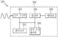
도 2b를 참조하면, 상기 무선 전력 수신장치는(200)는 전원 공급부(290)를 포함하도록 구성된다. 상기 전원 공급부(290)는 상기 무선 전력 수신장치(200)의 작동에 필요한 전력을 공급한다. 상기 전원 공급부(290)는 전력 수신부(291) 및 전력 수신 제어부(292)를 포함하여 구성될 수 있다.
Referring to FIG. 2B, the wireless
상기 전력 수신부(291)는 상기 무선 전력 전송장치로부터 무선으로 전달되는 전력을 수신한다.The
상기 전력 수신부(291)는 무선 전력 전달 방식에 따라 상기 무선 전력 신호를 수신하기 위해 필요한 구성 요소를 포함할 수 있다. 또한, 상기 전력 수신부(291)는 하나 이상의 무선 전력 전달 방식에 따라 전력을 수신할 수 있으며, 이 경우 상기 전력 수신부(291)는 각 방식에 따라 필요한 서로 구성 요소들을 함께 포함할 수 있다.The
먼저, 상기 전력 수신부(291)는 진동하는 특성을 가진 자기장 또는 전자기장의 형태로 전달되는 무선 전력 신호를 수신하기 위한 코일을 포함하도록 구성될 수 있다.First, the
예컨대, 유도 결합 방식에 따른 구성 요소로서, 상기 전력 수신부(291)는 변화되는 자기장에 의하여 전류가 유도되는 2차 코일을 포함할 수 있다. 또한, 상기 전력 수신부(291)는 공진 결합 방식에 따른 구성 요소로서 특정 공진 주파수를 가진 자기장에 의하여 공진 현상이 발생되는 코일 및 공진 회로를 포함할 수 있다.For example, as a component according to an inductive coupling scheme, the
다만, 상기 전력 수신부(291)가 하나 이상의 무선 전력 전달 방식에 따라 전력을 수신하는 경우, 상기 전력 수신부(291)는 하나의 코일을 이용하여 수신하도록 구현되거나, 또는 각 전력 전달 방식에 따라 다르게 형성된 코일을 이용하여 수신하도록 구현될 수 있다.However, when the
상기 전력 수신부(291)에 포함되는 구성 요소들 중 유도 결합 방식을 따르는 것들에 대하여는 도 4a 및 도 4b를 참조하여, 공진 결합 방식을 따르는 것들에 대하여는 도 7a 및 도 7b를 참조하여 후술된다.
Among the components included in the
한편, 상기 전력 수신부(291)는 상기 무선 전력 신호를 직류로 변환하기 위한 정류 회로(rectifier) 및 평활 회로(regulator)를 더 포함할 수 있다. 또한, 상기 전력 수신부(291)는 수신된 전력 신호에 의하여 과전압 또는 과전류가 발생하지 않도록 방지하는 회로를 더 포함할 수 있다.
Meanwhile, the
상기 전력 수신 제어부(292)는 상기 전원 공급부(290)에 포함되는 각 구성요소를 제어한다.The power
구체적으로, 상기 전력 수신 제어부(292)는 상기 무선 전력 전송장치로 전력 제어 메시지를 전달할 수 있다. 상기 전력 제어 메시지는 상기 무선 전력 전송장치에게 무선 전력 신호의 전달을 개시하거나 종료하도록 지시하는 것일 수 있다. 또한 상기 전력 제어 메시지는 상기 무선 전력 전송장치에게 상기 무선 전력 신호의 특성을 조절하도록 지시하는 것일 수 있다.Specifically, the power
이와 갈은 상기 전력 제어 메시지를 전송하기 위하여, 상기 전력 수신 제어부(292)는 상기 무선 전력 신호를 통하여 전송하는 방법 및 그 외의 사용자 데이터를 통하여 전송하는 방법 중 적어도 하나를 이용할 수 있다.In order to transmit the power control message, the
상기 전력 제어 메시지를 전송하기 위하여, 상기 무선 전력 수신장치(200)는 상기 전력 수신부(291)와 전기적으로 연결된 변복조부(Power Communications Modulation/Demodulation Unit)(293)를 더 포함하도록 구성될 수 있다. 상기 변복조부(293)는, 전술된 상기 무선 전력 전송장치의 경우와 마찬가지로, 상기 무선 전력 신호를 통하여 상기 전력 제어 메시지를 전송하기 위하여 사용될 수 있다. 상기 변복조부(293)는 상기 무선 전력 송신장치(100)의 전력 변환부(111)를 흐르는 전류 및/또는 전압을 조절하는 수단으로 사용될 수 있다. 이하, 상기 무선 전력 전송장치 측과 상기 무선 전력 수신장치(200) 측의 각각의 변복조부(113 및 293)가 무선 전력 신호를 통한 전력 제어 메시지의 송수신을 위하여 사용되는 방법에 대하여 설명된다.In order to transmit the power control message, the wireless
상기 전력 변환부(111)에 의하여 형성된 무선 전력 신호는 상기 전력 수신부(291)에 의하여 수신된다. 이때, 상기 전력 수신 제어부(292)는 상기 무선 전력 신호를 변조(modulation)하도록 상기 무선 전력 수신장치(200) 측의 변복조부(293)를 제어한다. 예컨대, 상기 전력 수신 제어부(292)는 상기 전력 수신부(291)과 연결된 변복조부(293)의 리액턴스(reactance)를 변경시킴으로써 상기 무선 전력 신호로부터 수신하는 전력량이 그에 따라 변하도록 변조 과정을 수행할 수 있다. 상기 무선 전력 신호로부터 수신되는 전력량의 변경은 상기 무선 전력 신호를 형성시키는 상기 전력 변환부(111)의 전류 및/또는 전압의 변경을 가져온다. 이 때, 상기 무선 전력 전송장치 측의 변복조부(113)는 상기 전력 변환부(111)의 전류 및/또는 전압의 변경을 감지하여 복조(demodulation) 과정을 수행한다.The wireless power signal formed by the
즉, 상기 전력 수신 제어부(292)는 상기 무선 전력 전송장치에게 전달하고자 하는 전력 제어 메시지를 포함하는 패킷(packet)을 생성하여 상기 패킷이 포함되도록 상기 무선 전력 신호를 변조하고, 상기 전력 송신 제어부(112)는 상기 변복조부(113)의 복조 과정 수행 결과를 기초로 상기 패킷을 디코드함으로써, 상기 패킷에 포함되어 있는 상기 전력 제어 메시지를 획득할 수 있다.That is, the
그 밖에, 어떤 실시 예들에서는 상기 전력 수신 제어부(292)가 상기 무선 전력 수신장치(200)에 포함되어 있는 통신 수단(미도시)에 의하여 전력 제어 메시지가 포함되어 있는 사용자 데이터를 전송함으로써 전력 제어 메시지를 상기 무선 전력 전송장치로 전송할 수도 있다.
In addition, in some embodiments, the power
[In-band two-way communication을 지원 하는 경우][When supporting in-band two-way communication]
또한, 본 명세서에 개시된 실시 예들을 따르는 양방향 통신이 가능한 무선 전력 전송환경에서는, 상기 전력 수신 제어부(292)가 상기 무선 전력 전송장치로부터 전송되는 데이터를 수신할 수 있다. 상기 무선 전력 전송장치로부터 전송되는 데이터는 전력 제어 메시지를 전송할 것을 요청하는 것일 수 있다.
In addition, in a wireless power transmission environment capable of bidirectional communication according to the embodiments disclosed herein, the power
그 밖에, 상기 전원 공급부(290)는 충전부(298) 및 배터리(299)를 더 포함하도록 구성될 수 있다.In addition, the
상기 전원 공급부(290)로부터 동작을 위한 전원을 공급받는 상기 무선 전력 수신장치(200)는 상기 무선 전력 전송장치로부터 전달된 전력에 의하여 동작하거나, 또는 상기 전달된 전력을 이용하여 상기 배터리(299)를 충전한 후 상기 배터리(299)에 충전된 전력에 의하여 동작할 수 있다. 이때, 상기 전력 수신 제어부(292)는 상기 전달된 전력을 이용하여 충전을 수행하도록 상기 충전부(298)를 제어할 수 있다.
The wireless
이하에서, 본 명세서에 개시된 실시 예들에 적용 가능한 무선 전력 전송장치 및 무선 전력 수신장치에 대하여 설명된다. 먼저, 도 3 내지 도 5를 참조하여 상기 무선 전력 전송장치가 상기 무선 전력 수신장치로 유도 결합 방식에 따라 전력을 전달하는 방법이 개시된다.
Hereinafter, a wireless power transmission apparatus and a wireless power receiving apparatus applicable to the embodiments disclosed herein will be described. 3 to 5, a method of transmitting power by the wireless power transmission apparatus to the wireless power reception apparatus according to an inductive coupling scheme is disclosed.
유도 결합 방식Inductively coupled
도 3은 유도 결합 방식에 따라 무선 전력 전송장치로부터 무선 전력 수신장치에 무선으로 전력이 전달되는 개념을 도시한다.3 illustrates a concept that power is transmitted from a wireless power transmission apparatus to a wireless power receiving apparatus wirelessly according to an inductive coupling scheme.
무선 전력 전송장치 의 전력 전달이 유도 결합 방식을 따르는 경우, 상기 전력 전달부(110) 내의 1차 코일(primary coil)에 흐르는 전류의 세기가 변화되면, 그 전류에 의해 1차 코일을 통과하는 자기장이 변화한다. 이와 같이 변화된 자기장은 상기 무선 전력 수신장치(200) 내의 2차 코일(secondary coil) 측에 유도 기전력을 발생시킨다.When the power transmission of the wireless power transmission apparatus follows the inductive coupling scheme, when the intensity of the current flowing through the primary coil in the
이 방식에 따르면, 상기 무선 전력 전송장치의 상기 전력 변환부(111)는 자기 유도에서의 1차 코일로 동작하는 전송 코일(Tx coil)(1111a)를 포함하도록 구성된다. 또한 상기 무선 전력 수신장치(200)의 상기 전력 수신부(291)는 자기 유도에서의 2차 코일로 동작하는 수신 코일(Rx coil)(2911a)을 포함하도록 구성된다.According to this scheme, the
먼저 상기 무선 전력 전송장치 측의 상기 전송 코일(1111a)과 상기 무선 전력 수신장치(200) 측의 수신 코일이 근접하도록 상기 무선 전력 전송장치 및 상기 무선 전력 수신장치(200)를 배치한다. 그 후 상기 전력 송신 제어부(112)가 상기 전송 코일(1111a)의 전류가 변화되도록 제어하면, 상기 전력 수신부(291)는 상기 수신 코일(2911a)에 유도된 기전력을 이용하여 상기 무선 전력 수신장치(200)에 전원을 공급하도록 제어한다.The wireless power transmission apparatus and the wireless
상기 유도 결합 방식에 의한 무선 전력 전달의 효율은, 주파수 특성에 따른 영향은 적으나, 각 코일을 포함하는 상기 무선 전력 전송장치 및 상기 무선 전력 수신장치(200) 사이의 배열(alignment) 및 거리(distance)의 영향을 받게 된다.
The efficiency of the wireless power transmission by the inductively coupled system is less influenced by the frequency characteristics but is influenced by the alignment and distance between the wireless power transmission apparatus including the coils and the wireless
한편, 유도 결합 방식에 의한 무선 전력 전달을 위하여 상기 무선 전력 전송장치는 평평한 표면(flat surface) 형태의 인터페이스 표면(interface surface)(미도시)을 포함하도록 구성될 수 있다. 상기 인터페이스 표면의 상부에는 하나 이상의 무선 전력 수신장치가 놓일 수 있으며, 상기 인터페이스 표면의 하부에는 상기 전송 코일(1111a)가 장착될 수 있다. 그 경우, 상기 인터페이스 표면의 하부에는 장착된 상기 전송 코일(1111a)과 상기 인터페이스 표면의 상부에 위치한 무선 전력 수신장치(200)의 수신 코일(2911a) 사이의 수직 공간(vertical spacing)이 작게 형성됨으로써 상기 코일들 간의 거리는 유도 결합 방식에 의한 무선 전력 전달이 효율적으로 이루어질 수 있도록 충분히 작게 된다.
On the other hand, for inductive coupling wireless power transmission, the wireless power transmission device may be configured to include an interface surface (not shown) in the form of a flat surface. One or more wireless power receiving devices may be disposed on the interface surface, and the
또한, 상기 인터페이스 표면의 상부에는 상기 무선 전력 수신장치(200)가 놓일 위치를 지시하는 배열 지시부(미도시)가 형성될 수 있다. 상기 배열 지시부는 상기 인터페이스 표면의 하부에 장착된 전송 코일(1111a)과 상기 수신 코일(2911a) 사이의 배열이 적합하게 이루어질 수 있는 상기 무선 전력 수신장치(200)의 위치를 지시한다. 상기 배열 지시부는 단순한 표시(marks)이거나, 상기 무선 전력 수신장치(200)의 위치를 가이드하는 돌출 구조의 형태로 형성될 수 있다. 또는 상기 배열 지시부는 상기 인터페이스 표면의 하부에 장착되는 자석과 같은 자성체의 형태로 형성되어, 상기 무선 전력 수신장치(200) 내부에 장착된 다른 극의 자성체와의 상호간 인력에 의하여 상기 코일들이 적합한 배열을 이루도록 가이드할 수도 있다.
In addition, an arrangement indicator (not shown) may be formed on the interface surface to indicate a position where the wireless
한편, 상기 무선 전력 전송장치는 하나 이상의 전송 코일을 포함하도록 형성될 수 있다. 상기 무선 전력 전송장치는 상기 하나 이상의 전송 코일 중에서 상기 무선 전력 수신장치(200)의 수신 코일(2911a)과 적합하게 배열된 일부의 코일을 선택적으로 이용하여 전력 전송 효율을 높일 수 있다. 상기 하나 이상의 전송 코일을 포함하는 무선 전력 전송장치에 관하여 도 5를 참조하여 후술된다.
Meanwhile, the wireless power transmission apparatus may be configured to include one or more transmission coils. The wireless power transmission apparatus may selectively use a part of the coils suitably arranged with the
이하에서는, 본 명세서에 개시된 실시 예들에 적용 가능한 유도 결합 방식의 무선 전력 전송장치 및 무선 전력 수신장치의 구성에 대하여 구체적으로 설명된다.
Hereinafter, a configuration of an inductively coupled wireless power transmission apparatus and a wireless power reception apparatus applicable to the embodiments disclosed herein will be described in detail.
유도 결합 방식의 무선 전력 전송장치 및 무선 전력 수신장치Inductively coupled wireless power transmission apparatus and wireless power receiving apparatus
도 4a 및 도 4b는 본 명세서에 개시된 실시 예들에서 채용 가능한 자기 유도 방식의 무선 전력 전송장치 및 무선 전력 수신장치(200)의 구성의 일부를 예시적으로 나타낸 블록도이다. 도 4a를 참조하여 상기 무선 전력 전송장치에 포함된 상기 전력 전달부(110)의 구성에 대하여 설명하고, 도 4b를 참조하여 상기 무선 전력 수신장치(200)에 포함된 상기 전원 공급부(290)의 구성에 대하여 설명한다.
4A and 4B are block diagrams illustrating a portion of the configuration of a wireless power transmission apparatus and a wireless
도 4a를 참조하면, 상기 무선 전력 전송장치의 상기 전력 변환부(111)는 전송 코일(Tx coil)(1111a) 및 인버터(1112)를 포함하도록 구성될 수 있다.Referring to FIG. 4A, the
상기 전송 코일(1111a)는, 전술된 바와 같이, 전류의 변화에 따라 무선 전력 신호에 해당하는 자기장을 형성한다. 상기 전송 코일(1111a)은 평판 나선형태(Planar Spiral type) 또는 원통형 솔레노이드 형태(Cylindrical Solenoid type)로 구현될 수 있다.As described above, the
상기 인버터(1112)는 상기 전원 공급부(190)로부터 얻은 직류 입력(DC input)을 교류 파형(AC waveform)으로 변형시킨다. 상기 인버터(1112)에 의해 변형된 교류 전류는 상기 전송 코일(1111a) 및 커패시터(capacitor)(미도시)를 포함하는 진동 회로(resonant circuit)를 구동시킴으로써 자기장이 상기 전송 코일(1111a)에서 형성된다.
The
그 밖에, 상기 전력 변환부(111)는 위치 결정부(Positioning Unit)(1114)를 더 포함하도록 구성될 수 있다.In addition, the
상기 위치 결정부(1114)는 상기 유도 결합 방식에 의한 무선 전력 전달의 효율을 높이기 위하여 상기 전송 코일(1111a)을 이동 또는 회전시킬 수 있다. 이는, 전술된 바와 같이, 유도 결합 방식에 의한 전력 전달은 1차 및 2차 코일을 포함하는 상기 무선 전력 전송장치 및 상기 무선 전력 수신장치(200) 사이의 배열(alignment) 및 거리(distance)의 영향을 받기 때문이다. 특히, 상기 위치 결정부(1114)는 상기 무선 전력 수신장치(200)가 상기 무선 전력 전송장치의 활동 영역 내에 존재하지 않는 경우에 사용될 수 있다.The
따라서, 상기 위치 결정부(1114)는 상기 무선 전력 전송장치의 상기 전송 코일(1111a)과 및 상기 무선 전력 수신장치(200)의 상기 수신 코일(2911a)의 중심간 거리(distance)가 일정 범위 이내가 되도록 상기 전송 코일(1111a)을 이동시키거나, 상기 전송 코일(1111a)과 상기 수신 코일(2911a)의 중심이 중첩되도록 상기 전송 코일(1111a)를 회전시키는 구동부(미도시)를 포함하도록 구성될 수 있다.Therefore, the
이를 위하여, 상기 무선 전력 전송장치는 상기 무선 전력 수신장치(200)의 위치를 감지하는 센서로 이루어진 위치 감지부(detection unit)(미도시)를 더 구비할 수 있고, 상기 전력 송신 제어부(112)는 상기 위치 감지 센서로부터 수신한 상기 무선 전력 수신장치(200)의 위치 정보를 기초로 상기 위치 결정부(1114)를 제어할 수 있다.The wireless power transmission apparatus may further include a position detection unit (not shown) configured to detect a position of the wireless
또한, 이를 위하여 상기 전력 송신 제어부(112)는 상기 변복조부(113)를 통하여 상기 무선 전력 수신장치(200)와의 배열 또는 거리에 대한 제어 정보를 수신하고, 상기 수신된 배열 또는 거리에 대한 제어 정보를 기초로 상기 위치 결정부(1114)를 제어할 수 있다.For this, the power
만약, 상기 전력 변환부(111)가 복수의 전송 코일을 포함하도록 구성되었다면, 상기 위치 결정부(1114)는 상기 복수의 전송 코일 중에서 어느 것이 전력 전달을 위하여 사용될 것인지 결정할 수 있다. 상기 복수의 전송 코일을 포함한 무선 전력 전송장치의 구성에 대해서는 도 5를 참조하여 후술된다.
If the
한편, 상기 전력 변환부(111)는 전력 센싱부(1115)를 더 포함하도록 구성될 수 있다. 상기 무선 전력 전송장치 측의 전력 센싱부(1115)는 상기 전송 코일(1111a)에 흐르는 전류 또는 전압을 모니터링한다. 상기 전력 센싱부(1115)는 무선 전력 전송장치의 정상동작 여부를 확인하기 위한 것으로, 외부로부터 공급되는 전원의 전압 또는 전류를 검출하고, 상기 검출된 전압 또는 전류가 임계값을 초과하는지를 확인할 수 있다. 상기 전력 센싱부(1115)는, 도시되지 않았으나, 외부로부터 공급되는 전원의 전압 또는 전류를 검출하기 위한 저항과 상기 검출된 전원의 전압값 또는 전류값과 임계값을 비교하여 그 비교 결과를 출력하는 비교기를 포함할 수 있다. 상기 전력 센싱부(1115)의 상기 확인 결과를 기초로, 상기 전력 송신 제어부(112)는 스위칭부(미도시)를 제어하여 상기 전송 코일(1111a)로 인가되는 전원을 차단할 수 있다.
Meanwhile, the
도 4b를 참조하면, 상기 무선 전력 수신장치(200)의 상기 전원 공급부(290)는 수신 코일(Rx 코일)(2911a) 및 정류 회로(2913)를 포함하도록 구성될 수 있다.Referring to FIG. 4B, the
상기 전송 코일(1111a)로부터 형성된 자기장에 변화에 의하여 상기 수신 코일(2911a)에서 전류가 유도된다. 상기 수신 코일(2911a)의 구현 형태는, 상기 전송 코일(1111a)의 경우와 마찬가지로, 평판 나선 형태 또는 원통형 솔레노이드 형태일 수 있다.A current is induced in the
또한, 무선 전력의 수신 효율을 높이거나 공진 감지(resonant detection)를 위해 직/병렬 커패시터들(series and parallel capacitors)이 상기 수신 코일(2911a)과 연결되도록 구성될 수 있다.In addition, series and parallel capacitors may be connected to the receiving
상기 수신 코일(2911a)은 단일 코일 또는 복수의 코일 형태일 수 있다.The receiving
상기 정류 회로(2913)는 교류를 직류로 변환시키기 위하여 전류에 대하여 전파 정류(full-wave rectification)를 수행한다. 상기 정류 회로(2913)는, 예컨대, 4개의 다이오드로 이루어진 브릿지(full bridge) 정류 회로, 또는 능동 소자(active components)를 이용한 회로로 구현될 수 있다.The
그 밖에, 상기 정류 회로(2913)는 정류된 전류를 보다 평탄하고 안정적인 직류로 만들어 주는 평활 회로(regulator)를 더 포함할 수 있다. 또한, 상기 정류 회로(2913)의 출력 전원은 상기 전원 공급부(290)의 각 구성 요소들에게 공급된다. 또한, 상기 정류 회로(2913)은 출력되는 직류 전원을 상기 전원 공급부(290)의 각 구성 요소(예컨대, 충전부(298)와 같은 회로)에 필요한 전원에 맞추기 위하여 적정한 전압으로 변환하는 직류-직류 변환기(DC-DC converter)를 더 포함할 수 있다.In addition, the
상기 변복조부(293)는 상기 전력 수신부(291)과 연결되고, 직류 전류에 대해서는 저항(resistance)이 변하는 저항성 소자로 구성될 수 있고, 교류 전류에 대해서는 리액턴스(reactance)가 변하는 용량성 소자로 구성될 수 있다. 상기 전력 수신 제어부(292)는 상기 변복조부(293)의 저항 또는 리액턴스를 변경시킴으로써 상기 전력 수신부(291)에 수신되는 무선 전력 신호를 변조할 수 있다.The modulation and
한편, 상기 전원 공급부(290)는 전력 센싱부(2914)를 더 포함하도록 구성될 수 있다. 상기 무선 전력 수신장치(200) 측의 전력 센싱부(2914)는 상기 정류 회로(2913)에 의하여 정류된 전원의 전압 및/또는 전류를 모니터링하고, 상기 모니터링 결과 상기 정류된 전원의 전압 및/또는 전류가 임계값을 초과하는 경우 상기 전력 수신 제어부(292)는 적절한 전력을 전달하도록 상기 무선 전력 전송장치에게 전력 제어 메시지를 송신한다.
The
하나 이상의 전송 코일을 포함하여 구성된 무선 전력 전송장치A wireless power transmission apparatus configured with one or more transmission coils
도 5는 본 명세서에 개시된 실시 예들에서 채용 가능한 유도 결합 방식에 따라 전력을 수신하는 하나 이상의 전송 코일들을 가지도록 구성된 무선 전력 전송장치의 블록도이다.5 is a block diagram of a wireless power transmission apparatus configured to have one or more transmission coils that receive power in accordance with an inductive coupling scheme employable in the embodiments disclosed herein.
도 5를 참조하면, 본 명세서에 개시된 실시 예들을 따르는 무선 전력 전송장치 의 전력 변환부(111)는 하나 이상의 전송 코일들(1111a-1 내지 1111a-n)로 구성될 수 있다. 상기 하나 이상의 전송 코일들(1111a-1 내지 1111a-n)은 부분적으로 겹치는 1차 코일들의 배열(an array of partly overlapping primary coils)일 수 있다. 상기 하나 이상의 전송 코일들 중 일부에 의하여 활동 영역이 결정될 수 있다.Referring to FIG. 5, the
상기 하나 이상의 전송 코일들(1111a-1 내지 1111a-n)은 상기 인터페이스 표면의 하부에 장착될 수 있다. 또한, 상기 전력 변환부(111)는 상기 하나 이상의 전송 코일들(1111a-1 내지 1111a-n) 중 일부의 코일들의 연결을 수립하고 해제하는 다중화기(Multiplexer)(1113)를 더 포함할 수 있다.The one or
상기 인터페이스 표면의 상부에 놓인 무선 전력 수신장치(200)의 위치가 감지되면, 상기 전력 송신 제어부(112)는 상기 무선 전력 수신장치(200)의 감지된 위치를 고려하여 상기 하나 이상의 전송 코일들(1111a-1 내지 1111a-n) 중 상기 무선 전력 수신장치(200)의 수신 코일(2911a)과 유도 결합 관계에 놓일 수 있는 코일들이 연결될 수 있도록 상기 다중화기(1113)를 제어할 수 있다.When the position of the wireless
이를 위하여 상기 전력 송신 제어부(112)가 상기 무선 전력 수신장치(200)의 위치 정보를 획득할 수 있다. 예를 들어, 상기 전력 송신 제어부(112)는 상기 무선 전력 전송장치에 구비된 상기 위치 감지부(미도시)에 의하여 상기 인터페이스 표면 상의 상기 무선 전력 수신장치(200)의 위치를 획득할 수 있다. 또 다른 예를 들어, 상기 전력 송신 제어부(112)는 상기 하나 이상의 전송 코일들(1111a-1 내지 1111a-n)을 각각 이용하여 상기 인터페이스 표면 상의 물체로부터 무선 전력 신호의 강도를 나타내는 전력 제어 메시지 또는 상기 물체의 식별 정보를 나타내는 전력 제어 메시지를 수신하고, 상기 수신된 결과를 기초로 상기 하나 이상의 전송 코일들 중 어느 코일의 위치와 근접한지를 판단함으로써 상기 무선 전력 수신장치(200)의 위치 정보를 획득할 수도 있다.For this, the power
한편, 상기 활동 영역은 상기 인터페이스 표면의 일부로서, 상기 무선 전력 전송장치가 상기 무선 전력 수신장치(200)에 무선으로 전력을 전달할 때 높은 효율의 자기장이 통과할 수 있는 부분을 의미할 수 있다. 이 때, 상기 활동 영역을 통과하는 자기장을 형성시키는 단일 전송 코일 또는 하나 이상의 전송 코일들의 조합을 주요 셀(primary cell)로 지칭할 수 있다. 따라서, 상기 전력 송신 제어부(112)는 상기 무선 전력 수신장치(200)의 감지된 위치를 기초로 활동 영역을 결정하고, 상기 활동 영역에 대응되는 주요 셀의 연결을 수립하여 상기 무선 전력 수신장치(200)의 수신 코일(2911a)와 상기 주요 셀에 속한 코일들이 유도 결합 관계에 놓일 수 있도록 상기 다중화기(1113)을 제어할 수 있다.On the other hand, the active area may be a part of the interface surface, and may refer to a portion through which a high efficiency magnetic field can pass when the wireless power transmission apparatus transmits power wirelessly to the wireless
또한, 상기 전력 변환부(111)는 연결된 코일들과 진동 회로(resonant circuit)를 형성하도록 임피던스를 조절하는 임피던스 매칭부(impedance matching unit)(미도시)를 더 포함할 수 있다.
The
이하에서, 도 6 내지 도 8을 참조하여 무선 전력 전송장치가 공진 결합 방식에 따라 전력을 전달하는 방법이 개시된다.
Hereinafter, a method of transmitting power according to a resonant coupling scheme by a wireless power transmission apparatus is described with reference to FIGS.
공진 결합 방식Resonance coupling method
도 6은 공진 결합 방식에 따라 무선 전력 전송장치로부터 무선 전력 수신장치에 무선으로 전력이 전달되는 개념을 도시한다.FIG. 6 illustrates a concept that power is transmitted from a wireless power transmission apparatus to a wireless power reception apparatus wirelessly according to a resonant coupling scheme.
먼저, 공진(resonance)(또는 공명)에 대해 간략하게 설명하면 다음과 같다. 공진(resonance)이란, 진동계가 그 고유 진동수와 같은 진동수를 가진 외력을 주기적으로 받아 진폭이 뚜렷하게 증가하는 현상을 말한다. 공진은 역학적 진동 및 전기적 진동 등 모든 진동에서 일어나는 현상이다. 일반적으로 외부에서 진동계에 진동시킬 수 있는 힘을 가했을 때 그 진동계의 고유 진동수와 외부에서 가해주는 힘의 진동수가 같으면 그 진동은 심해지고 진폭도 커진다.First, the resonance (or resonance) will be briefly described as follows. Resonance refers to a phenomenon in which the vibration system receives an external force periodically having the same frequency as its natural frequency, and the amplitude thereof increases sharply. Resonance is a phenomenon occurring in all vibrations, such as mechanical vibration and electrical vibration. Generally, when a force capable of vibrating the vibration system is applied from the outside, if the natural frequency of the vibration system is equal to the frequency of the external force, the vibration becomes larger and the amplitude becomes larger.
같은 원리로, 일정 거리 내에서 떨어져 있는 복수의 진동체들이 서로 동일한 주파수로 진동하는 경우, 상기 복수의 진동체들은 상호 공진하며, 이 경우 상기 복수의 진동체들 간에는 저항이 감소하게 된다. 전기 회로에서는 인덕터과 커패시터를 사용하여 공진 회로를 만들 수 있다.In the same principle, when a plurality of vibrating bodies separated within a certain distance oscillate at the same frequency, the plurality of vibrating bodies resonate with each other, and in this case, the resistance between the vibrating bodies decreases. In an electric circuit, an inductor and a capacitor can be used to make a resonant circuit.
무선 전력 전송장치의 전력 전달이 공진 결합 방식을 따르는 경우, 상기 전력 전달부(110)에서 교류 전원에 의하여 특정한 진동 주파수를 가진 자기장이 형성된다. 상기 형성된 자기장에 의하여 상기 무선 전력 수신장치(200)에서 공진 현상이 일어나는 경우 상기 무선 전력 수신장치(200) 내에서는 상기 공진 현상에 의하여 전력이 발생된다.When the power transmission of the wireless power transmission apparatus follows the resonant coupling scheme, a magnetic field having a specific vibration frequency is formed by the AC power source in the
공진 주파수는, 예를 들어, 다음 수학식 1과 같은 수식에 의하여 결정될 수 있다.The resonance frequency can be determined by, for example, the following equation (1).

여기서, 공진 주파수 (f)는 회로 내의 인덕턴스(L) 및 커패시턴스(C)에 의하여 결정된다. 코일을 사용하여 자기장을 형성하는 회로에 있어서 상기 인덕턴스는 상기 코일의 회전 수 등에 의하여 결정되고, 상기 커패시턴스는 상기 코일 사이의 간격, 면적 등에 의하여 결정될 수 있다. 상기 공진 주파수를 결정하기 위하여 상기 코일 외에 용량성 공진 회로가 연결되도록 구성될 수도 있다.
Here, the resonance frequency f is determined by the inductance L and the capacitance C in the circuit. In a circuit for forming a magnetic field using a coil, the inductance is determined by the number of revolutions of the coil and the like, and the capacitance can be determined by an interval, an area, or the like between the coils. A capacitive resonance circuit may be connected to the coil to determine the resonance frequency.
도 6을 참조하면, 공진 결합 방식에 따라 무선으로 전력이 전송되는 경우, 상기 무선 전력 전송장치의 상기 전력 변환부(111)는 자기장이 형성되는 전송 코일(Tx coil)(1111b) 및 상기 전송 코일(1111b)와 연결되고 특정한 진동 주파수를 결정하기 위한 공진 회로(1116)를 포함하도록 구성될 수 있다. 상기 공진 회로(1116)는 용량성 회로(capacitors)를 이용하여 구현될 수 있으며, 상기 전송 코일(1111b)의 인덕턴스 및 상기 공진 회로(1116)의 커패시턴스를 기초로 상기 특정한 진동 주파수가 결정된다.Referring to FIG. 6, when power is transmitted wirelessly according to the resonant coupling scheme, the
상기 공진 회로(1116)의 회로 소자의 구성은 상기 전력 변환부(111)가 자기장을 형성할 수 있도록 다양한 형태로 이루어질 수 있으며, 도 6과 같이 상기 전송 코일(1111b)과 병렬로 연결되는 형태로 제한되지 아니한다.The configuration of the circuit elements of the
또한, 상기 무선 전력 수신장치(200)의 상기 전력 수신부(291)는 상기 무선 전력 전송장치에서 형성된 자기장에 의하여 공진 현상이 일어날 수 있도록 구성된 공진 회로(2912) 및 수신 코일(Rx coil)(2911b)을 포함한다. 즉, 상기 공진 회로(2912)는 역시 용량성 회로를 이용하여 구현될 수 있으며, 상기 공진 회로(2912)는 상기 수신 코일(2911b)의 인덕턴스와 상기 공진 회로(2912)의 커패시턴스를 기초로 결정되는 공진 주파수가 상기 형성된 자기장의 공진 주파수와 동일하도록 구성된다.The
상기 공진 회로(2912)의 회로 소자의 구성은 상기 전력 수신부(291)가 상기 자기장에 의하여 공진이 일어날 수 있도록 다양한 형태로 이루어질 수 있으며, 도 6과 같이 상기 수신 코일(2911b)과 직렬로 연결되는 형태로 제한되지 아니한다. The configuration of the circuit elements of the
상기 무선 전력 전송장치에서의 상기 특정한 진동 주파수는 LTx, CTx를 가지고 상기 수학식 1을 이용하여 획득될 수 있다. 여기서, 상기 무선 전력 수신장치(200)의 LRX 및 CRX를 상기 수학식 1에 대입한 결과가 상기 특정한 진동 주파수와 동일한 경우에 상기 무선 전력 수신장치(200)에서는 공진이 일어난다.The specific vibration frequency in the wireless power transmission apparatus may be obtained using
상기 공진 결합 방식에 의한 무선 전력 전달의 효율은, 주파수 특성에 따른 영향이 큰 반면, 각 코일을 포함하는 상기 무선 전력 전송장치 및 상기 무선 전력 수신장치(200) 사이의 배열 및 거리에 따른 영향은 유도 결합 방식에 비해 상대적으로 작다.
The efficiency of the wireless power transmission by the resonance coupling method is largely influenced by the frequency characteristics, while the influence of the arrangement and the distance between the wireless power transmission apparatus including the coils and the wireless
이하에서는, 본 명세서에 개시된 실시 예들에 적용 가능한 공진 결합 방식의 무선 전력 전송장치 및 무선 전력 수신장치의 구성에 대하여 구체적으로 설명된다.
Hereinafter, a configuration of a wireless power transmission apparatus and a wireless power reception apparatus of a resonance coupling type applicable to the embodiments disclosed herein will be described in detail.
공진 결합 방식의 무선 전력 전송장치Resonant coupling type wireless power transmission device
도 7a 및 도 7b는 본 명세서에 개시된 실시 예들에서 채용 가능한 공진 방식의 무선 전력 전송장치 및 무선 전력 수신장치(200)의 구성의 일부를 예시적으로 나타낸 블록도이다.7A and 7B are block diagrams exemplarily showing a part of the configuration of a wireless power transmission apparatus and a wireless
도 7a를 참조하여 상기 무선 전력 전송장치에 포함된 상기 전력 전달부(110)의 구성에 대하여 설명된다.The configuration of the
상기 무선 전력 전송장치의 상기 전력 변환부(111)는 전송 코일(Tx coil)(1111b), 인버터(1112) 및 공진 회로(1116)를 포함하도록 구성될 수 있다. 상기 인버터(1112)는 상기 전송 코일(1111b) 및 상기 공진 회로(1116)와 연결되도록 구성될 수 있다.The
상기 전송 코일(1111b)은 유도 결합 방식에 따라 전력을 전달하기 위한 전송 코일(1111a)과 별도로 장착될 수 있으나, 하나의 단일 코일을 이용하여 유도 결합 방식 및 공진 결합 방식으로 전력을 전달할 수도 있다.The
상기 전송 코일(1111b)은, 전술된 바와 같이, 전력을 전달하기 위한 자기장을 형성한다. 상기 전송 코일(1111b) 및 상기 공진 회로(1116)는 교류 전원이 인가되면 진동이 발생할 수 있으며, 이 때 상기 전송 코일(1111b)의 인덕턴스 및 상기 공진 회로(1116)의 커패시턴스를 기초로 진동 주파수가 결정될 수 있다.The
이를 위하여 상기 인버터(1112)는 상기 전원 공급부(190) 로부터 얻은 직류 입력을 교류 파형으로 변형시키고, 상기 변형된 교류 전류가 상기 전송 코일(1111b) 및 상기 공진 회로(1116)에 인가된다.To this end, the
그 밖에, 상기 전력 변환부(111)는 상기 전력 변환부(111)의 공진 주파수 값을 변경시키기 위한 주파수 조절부(1117)를 더 포함하도록 구성될 수 있다. 상기 전력 변환부(111)의 공진 주파수는 수학식 1에 의하여 상기 전력 변환부(111)를 구성하는 회로내의 인덕턴스 및 커패시턴스를 기초로 결정되므로, 상기 전력 송신 제어부(112)는 상기 인덕턴스 및/또는 커패시턴스가 변경되도록 상기 주파수 조절부(1117)를 제어함으로써 상기 전력 변환부(111)의 공진 주파수를 결정할 수 있다.In addition, the
상기 주파수 조절부(1117)는, 예를 들어, 상기 공진 회로(1116)에 포함된 커패시터 간의 거리를 조절하여 커패시턴스를 변경시킬 수 있는 모터를 포함하거나, 또는 상기 전송 코일(1111b)의 회전 수(number of turns) 또는 직경을 조절하여 인덕턴스를 변경시킬 수 있는 모터를 포함하거나, 또는 상기 커패시턴스 및/또는 인덕턴스를 결정하는 능동 소자들을 포함하도록 구성될 수 있다.The
한편, 상기 전력 변환부(111)는 전력 센싱부(1115)를 더 포함하도록 구성될 수 있다. 상기 전력 센싱부(1115)의 동작에 대해서는 전술된 바와 동일하다.
Meanwhile, the
도 7b를 참조하여 상기 무선 전력 수신장치(200)에 포함된 상기 전원 공급부(290)의 구성에 대하여 설명된다. 상기 전원 공급부(290)는, 전술된 바와 같이, 상기 수신 코일(Rx coil)(2911b) 및 공진 회로(2912)를 포함하도록 구성될 수 있다.The configuration of the
그 외에도, 상기 전원 공급부(290)의 전력 수신부(291)는 공진 현상에 의하여 생성된 교류 전류를 직류로 변환시키는 정류 회로(2913)를 더 포함하도록 구성될 수 있다. 상기 정류 회로(2913)는 전술된 바와 동일하게 구성될 수 있다.In addition, the
또한, 상기 전력 수신부(291)는 정류된 전원의 전압 및/또는 전류를 모니터링하는 전력 센싱부(2914)를 더 포함하도록 구성될 수 있다. 상기 전력 센싱부(2914)는 전술된 바와 동일하게 구성될 수 있다.The
하나 이상의 전송 코일을 포함하여 구성된 무선 전력 전송장치A wireless power transmission apparatus configured with one or more transmission coils
도 8은 본 명세서에 개시된 실시 예들에서 채용 가능한 공진 결합 방식에 따라 전력을 수신하는 하나 이상의 전송 코일들을 가지도록 구성된 무선 전력 전송장치의 블록도이다.8 is a block diagram of a wireless power transmission apparatus configured to have one or more transmission coils that receive power in accordance with a resonant coupling scheme employable in the embodiments disclosed herein.
도 8을 참조하면, 본 명세서에 개시된 실시 예들을 따르는 무선 전력 전송장치의 전력 변환부(111)는 하나 이상의 전송 코일들(1111b-1 내지 1111b-n) 및 각 전송 코일들과 연결된 공진 회로(1116-1 내지 1116-n)를 포함하도록 구성될 수 있다. 또한, 상기 전력 변환부(111)는 상기 하나 이상의 전송 코일들(1111b-1 내지 1111b-n) 중 일부의 코일들의 연결을 수립하고 해제하는 다중화기(Multiplexer)(1113)를 더 포함할 수 있다.8, the
상기 하나 이상의 전송 코일들(1111b-1 내지 1111b-n)은 동일한 공진 주파수를 갖도록 설정되거나, 일부가 서로 다른 공진 주파수를 갖도록 설정될 수 있다. 이는 상기 하나 이상의 전송 코일들(1111b-1 내지 1111b-n)과 각각 연결된 상기 공진 회로(1116-1 내지 1116-n)들이 어떠한 인덕턴스 및/또는 커패시턴스를 갖는지에 따라 결정된다.The one or more transmission coils 1111b-1 to 1111b-n may be set to have the same resonance frequency, or may be set so that some have different resonance frequencies. Which is determined according to what inductance and / or capacitance the resonant circuits 1116-1 through 1116-n respectively connected to the one or more transmission coils 1111b-1 through 1111b-n have.
이를 위하여, 상기 주파수 조절부(1117)는 상기 하나 이상의 전송 코일들(1111b-1 내지 1111b-n)과 각각 연결된 상기 공진 회로(1116-1 내지 1116-n)들의 인덕턴스 및/또는 커패시턴스를 변경시킬 수 있도록 구성될 수 있다.
The
[[In-band communication]][[In-band communication]]
도 9는 본 명세서에 개시된 실시 예들을 따르는 무선 전력 전달에 있어서 무선 전력 신호의 변조 및 복조를 통하여 무선 전력 전송장치와 전자 기기 사이에 패킷을 송수신하는 개념을 도시한다.9 illustrates a concept of transmitting and receiving packets between a wireless power transmission device and an electronic device through modulation and demodulation of a wireless power signal in wireless power transmission according to the embodiments disclosed herein.
도 9를 참조하면, 무선 전력 전송장치에 포함된 상기 전력 변환부(111)는 무선 전력 신호를 형성한다. 상기 무선 전력 신호는 상기 전력 변환부(111)에 포함된 전송 코일(1111)을 통하여 형성된다.Referring to FIG. 9, the
상기 전력 변환부(111)에 의하여 형성된 무선 전력 신호(10a)는 전자 기기(200)에 도달하여, 상기 전자 기기(200)에 포함된 전력 수신부(291)를 통하여 수신된다. 상기 형성된 무선 전력 신호는 상기 전력 수신부(291)에 포함된 수신 코일(2911)을 통하여 수신된다.The
상기 전력 수신 제어부(292)는 상기 전력 수신부(291)와 연결된 상기 변복조부(293)을 제어하여 상기 전자 기기(200)가 상기 무선 전력 신호를 수신하는 중에 상기 무선 전력 신호를 변조(modulation)한다. 상기 수신되는 무선 전력 신호가 변조되는 경우에 상기 무선 전력 신호는 자기장(magnetic field) 또는 전자기장(electro-magnetic field) 내에서 폐루프(closed-loop)를 형성하므로 상기 전자 기기(200)가 상기 무선 전력 신호를 수신하는 중에 상기 무선 전력 신호를 변조(modulation)하는 경우, 상기 무선 전력 전송장치는 변조된 무선 전력 신호(10b)를 감지할 수 있다. 상기 변복조부(113)는 상기 감지된 무선 전력 신호를 복조(demodulation)하고, 복조된 무선 전력 신호로부터 상기 패킷을 디코드할 수 있다.The power
한편, 상기 무선 전력 전송장치와 상기 전자 기기(200) 간의 통신에 사용되는 변조 방법은 진폭 변조(Amplitude Modulation)일 수 있다. 전술된 바와 같이, 상기 진폭 변조 방식은 상기 전력 변환부(111)가 형성한 무선 전력 신호(10a)의 진폭을 상기 전자 기기(200) 측의 변복조부(293)가 변경시켜 상기 무선 전력 전송장치 측의 변복조부(293)가 상기 변조된 무선 전력 신호(10b)의 진폭을 검출하는 백스캐터 변조(backscatter modulation) 방식일 수 있다.
Meanwhile, a modulation method used for communication between the wireless power transmission apparatus and the
무선 전력 신호의 변조 및 복조Modulation and demodulation of wireless power signals
이하, 도 10, 도 11a, 도 11b 및 도 11c을 참조하여 상기 무선 전력 전송장치 및 상기 전자 기기(200) 사이에서 송수신되는 패킷의 변조 및 복조에 대하여 설명된다.Modulation and demodulation of packets transmitted and received between the wireless power transmission apparatus and the
도 10은 본 명세서에 개시된 실시 예들을 따르는 무선 전력 전송에서 전력 제어 메시지를 송수신하기 위한 구성을 도시한다. 도 11a, 도 11b 및 도 11c는 본 명세서에 개시된 실시 예들을 따르는 무선 전력 전송에서 수행되는 변조 및 복조에서의 신호의 형태를 도시한다.10 illustrates a configuration for transmitting and receiving a power control message in a wireless power transmission according to the embodiments disclosed herein. 11A, 11B, and 11C illustrate the form of signals in modulation and demodulation performed in a wireless power transmission in accordance with the embodiments disclosed herein.
도 10을 참조하면, 상기 전자 기기(200) 측의 상기 전력 수신부(291)를 통하여 수신되는 무선 전력 신호는 도 11a 에 도시된 바와 같이 변조되지 않은 무선 전력 신호(51)이다. 상기 전력 수신부(291) 내의 공진 형성 회로(2912)에 의하여 설정된 공진 주파수에 따라 상기 전자 기기(200) 및 상기 무선 전력 전송장치 사이에 공진 결합이 이루어지고, 상기 수신 코일(2911b)을 통하여 상기 무선 전력 신호(51)가 수신된다.Referring to FIG. 10, a wireless power signal received through the
전력 수신 제어부(292)는 상기 전력 수신부(291)을 통하여 수신되는 무선 전력 신호(51)를 상기 변복조부(293) 내의 부하 임피던스(Impedance)를 변경시킴으로써 변조한다. 상기 변복조부(293)는 상기 무선 전력 신호(51)를 변조하기 위한 수동 소자(2931) 및 능동 소자(2932)를 포함하도록 구성될 수 있다. 상기 변복조부(293)는 상기 무선 전력 전송장치로 전송하고자 하는 패킷이 포함되도록 상기 무선 전력 신호(51)를 변조한다. 이때, 상기 패킷은 상기 변복조부(293) 내의 상기 능동 소자(2932)에 입력될 수 있다.The power
그 후, 상기 무선 전력 전송장치 측의 전력 송신 제어부(112)는 상기 변조된 무선 전력 신호(52)를 포락선 검출(Envelop Detection) 과정을 통하여 복조하고, 상기 검출된 신호(53)를 디지털 데이터(54)로 디코드한다. 상기 복조 과정은 변조된 무선 전력 신호에 의하여 상기 전력 변환부(111)를 흐르는 전류 또는 전압이 HI 상태(HI state) 및 LO 상태(LO state)로 두 가지 상태로 구분되는 것을 감지하고, 상기 상태들에 따라 구분되는 디지털 데이터를 기초로 상기 전자 기기(200)가 전송하고자 하는 패킷을 획득하는 것이다.Thereafter, the power
이하에서는, 상기 무선 전력 전송장치가 복조된 디지털 데이터로부터 상기 전자 기기(200)가 전송하고자 하는 전력 제어 메시지를 획득하는 과정을 설명한다.Hereinafter, the process of acquiring the power control message to be transmitted by the
도 11b 를 참조하면, 상기 전력 송신 제어부(112)는 포락선 검출된 신호로부터 클럭 신호(CLK)를 이용하여 인코딩된 비트를 검출한다. 상기 검출되는 인코딩된 비트는 상기 전자 기기(200) 측의 변조 과정에서 사용된 비트 인코딩 방법에 따라 인코딩 된 것이다. 어떤 실시 예들에서, 상기 비트 인코딩 방법은 NRZ(non-return to zero)일 수 있다. 어떤 실시 예들에서는, 상기 비트 인코딩 방법이 2-위상(bi-phase) 인코딩일 수 있다.Referring to FIG. 11B, the power
예컨대, 어떤 실시 예들에서, 상기 검출되는 비트는 차동 2-위상(differential bi-phase; DBP) 인코딩된 것일 수 있다. 상기 DBP 인코딩에 의하면, 상기 전자 기기(200) 측의 전력 수신 제어부(292)는 데이터 비트 1을 인코딩하기 위하여 두 번의 상태 전이(transitions)를 갖도록 하고, 데이터 비트 0을 인코딩하기 위하여 한 번의 상태 전이를 갖도록 한다. 즉, 데이터 비트 1은 상기 클럭 신호의 상승 에지(rising edge) 및 하강 에지(falling edge)에서 HI 상태 및 LO 상태간의 전이가 발생하도록 인코딩된 것이고, 데이터 비트 0은 상기 클럭 신호의 상승 에지에서 HI 상태 및 LO 상태간의 전이가 발생하도록 인코딩된 것일 수 있다.For example, in some embodiments, the detected bits may be differential bi-phase (DBP) encoded. According to the DBP encoding, the power
한편, 상기 전력 송신 제어부(112)는 비트 인코딩 방법에 따라 검출된 비트열로부터 패킷을 구성하는 바이트 포맷(byte format)을 이용하여 바이트 단위의 데이터를 획득할 수 있다. 어떤 실시 예들에서, 상기 검출된 비트열은 도 11c에 도시된 바와 같은 11 비트 비동기 직렬 포맷(11-bit asynchronous serial format)을 이용하여 전송된 것일 수 있다. 즉, 바이트의 시작을 알리는 시작 비트(start bit)와 종료를 알리는 종료 비트(stop)를 포함하고, 시작 비트와 종료 비트 사이에 데이터 비트들(b0 내지 b7)을 포함할 수 있다. 또한, 데이터의 오류를 검사하기 위한 패러티 비트(parity bit)가 추가될 수 있다. 상기 바이트 단위의 데이터는 전력 제어 메시지를 포함하는 패킷을 구성한다.
On the other hand, the power
[in-band two-way communication을 지원하는 경우][When in-band two-way communication is supported]
이상, 도 9에는 상기 무선 전력 전송 장치(100)가 형성한 반송파 신호(carrier signal)(10a)를 이용하여 상기 무선 전력 수신장치(200)가 패킷을 송신하는 것에 대하여 도시되었으나, 상기 무선 전력 전송 장치(100)도 위와 유사한 방식으로 상기 무선 전력 수신장치(200)에 데이터를 전송할 수 있다.Although the wireless
즉, 상기 전력 송신 제어부(112)는 상기 변복조부(113)를 제어하여 상기 무선 전력 수신장치(200)에 보낼 데이터가 상기 반송파 신호(10a)에 실리도록 변조할 수 있다. 이와 같은 경우 상기 무선 전력 수신장치(200) 측의 상기 전력 수신 제어부(292)가 상기 변조된 상기 반송파 신호(10a)로부터 데이터를 획득할 수 있도록 상기 변복조부(293)를 제어하여 복조를 수행할 수 있다.
That is, the power
패킷 포맷Packet format
이하에서는, 본 명세서에 개시된 실시 예들을 따르는 무선 전력 신호를 이용한 통신에서 사용되는 패킷의 구조가 설명된다.Hereinafter, the structure of a packet used in communication using a wireless power signal according to the embodiments disclosed herein will be described.
도 12a, 도 12b 및 도 12c는 본 명세서에 개시된 실시 예들을 따르는 무선 전력 전달방법에 사용되는 전력 제어 메시지를 포함하는 패킷을 도시한다.12A, 12B and 12C illustrate a packet including a power control message used in a wireless power transfer method according to the embodiments disclosed herein.
도 12a를 참조하면, 상기 무선 전력 전송장치 및 상기 전자 기기(200)는 전송하고자 하는 데이터를 명령 패킷(command_packet)(510)의 형태로 송수신할 수 있다. 상기 명령 패킷(510)은 헤더(511) 및 메시지(512)를 포함하도록 구성될 수 있다.Referring to FIG. 12A, the wireless power transmission apparatus and the
상기 헤더(511)는 상기 메시지(512)에 포함되는 데이터의 종류를 지시하는 필드를 포함할 수 있다. 상기 데이터의 종류를 지시하는 필드가 나타내는 값을 기초로 상기 메시지의 크기 및 그 종류가 결정될 수 있다.The
또한, 상기 헤더(511)는 상기 패킷의 발신자를 식별할 수 있는 주소 필드를 포함할 수 있다. 예컨대, 상기 주소 필드는 상기 전자 기기(200)의 식별자 또는 상기 전자 기기(200)가 속한 그룹의 식별자를 나타낼 수 있다. 상기 전자 기기(200)가 상기 패킷(510)을 전송하고자 하는 경우에, 상기 전자 기기(200)는 상기 패킷(510)의 상기 주소 필드가 자신의 식별 정보를 나타내도록 상기 패킷(510)을 생성할 수 있다.In addition, the
상기 메시지(512)는 상기 패킷(510)의 발신자가 전송하고자 하는 데이터를 포함한다. 상기 메시지(512)에 포함되는 데이터는 상대방에 대한 보고 사항(report), 요청 사항(request) 또는 응답 사항(response)일 수 있다.The
한편, 어떤 실시 예에 있어서, 상기 명령 패킷(510)은 도 12b에 도시된 바와 같이 구성될 수 있다. 상기 명령 패킷(510)에 포함된 상기 헤더(511)는 일정한 크기로 표현될 수 있다. 예컨대, 상기 헤더(511)는 두 바이트의 크기일 수 있다.Meanwhile, in some embodiments, the
상기 헤더(511)는 수신 주소 필드(5111)를 포함하도록 구성될 수 있다. 예컨대, 상기 수신 주소 필드는 6 비트의 크기일 수 있다.The
상기 헤더(511)는 OCF(Operation command field)(5112) 또는 OGF(Operation group field)(5113)를 포함하도록 구성될 수 있다. OGF(5113)는 상기 전자 기기(200)를 위한 커맨드의 그룹별로 부여되는 값이며, OCF(5112)는 상기 전자 기기(200)가 포함된 각 그룹 내에 존재하는 커맨드 별로 부여되는 값이다.The
상기 메시지(512)는 파라미터의 길이(length) 필드(5121a)와 파라미터의 값(value) 필드(5122a)로 구분하여 표현될 수 있다. 즉, 상기 패킷(510)의 발신자는 상기 메시지를 상기 전송하고자 하는 데이터를 표현하기 위해 필요한 하나 이상의 파라미터의 길이-값 쌍(5121a-5122a 등)의 형태로 구성할 수 있다.The
도 12c를 참조하면, 상기 무선 전력 전송장치 및 상기 전자 기기(200)는 상기 명령 패킷(510)에 전송을 위한 프리앰블(520) 및 체크섬(530)을 부가한 패킷의 형태로 상기 데이터를 송수신 할 수 있다.Referring to FIG. 12C, the wireless power transmission apparatus and the
상기 프리앰블(520)은 상기 무선 전력 전송장치가 수신되는 데이터와 동기화를 수행하고 상기 명령 패킷(510)의 시작 비트를 정확히 검출하기 위해 사용된다. 상기 프리앰블(520)은 동일한 비트가 반복되도록 구성될 수 있다. 예컨대, 상기 프리앰블(520)은 상기 DBP 인코딩에 따른 데이터 비트 1이 11번 내지 25번 반복되도록 구성될 수 있다.The
상기 체크섬(530)은 전력 제어 메시지가 전송되는 도중에 상기 명령 패킷(510)에 발생할 수 있는 오류를 감지하기 위하여 사용된다.
The
동작 상태(Phases)Phases
이하에서, 일대일 통신에 있어서, 상기 무선 전력 전송장치 및 상기 무선 전력 수신장치(200)의 동작 상태들에 대하여 설명된다.Hereinafter, the operation states of the wireless power transmission apparatus and the wireless
도 13은 본 명세서에 개시된 실시 예들을 따르는 무선 전력 전송장치 및 무선 전력 수신장치(200)의 동작 상태들을 도시한다. 또한, 도 14 내지 도 18은 상기 무선 전력 전송장치 및 무선 전력 수신장치(200)간의 전력 제어 메시지를 포함하는 패킷들의 구조를 도시한다.13 illustrates operating states of a wireless power transmission apparatus and a wireless
도 13을 참조하면, 익스클루시브 방식을 따르는, 무선 전력 전송을 위한 무선 전력 수신장치(200)의 동작 상태는 선택 상태(Selection Phase) (610), 검출 상태(Ping Phase)(620), 식별 및 설정 상태(Identification and Configuration Phase)(630), 그리고 전력 전송 상태(Power Transfer Phase)(640)로 구분될 수 있다.13, an operation state of a wireless
상기 선택 상태(610)에서는 상기 무선 전력 전송장치가 무선으로 전력을 전송할 수 있는 범위 내에 물체(object)들이 존재하는지 여부를 감지하고, 상기 검출 상태(620)에서는 상기 무선 전력 전송장치가 상기 감지된 물체로 검출 신호를 보내고, 상기 무선 전력 수신장치(200)는 상기 검출 신호에 대한 응답을 보낸다.In the selected
또한, 상기 식별 및 설정 상태(630)에서는 상기 무선 전력 전송장치가 이전 상태들을 통하여 선택된 무선 전력 수신장치(200)를 식별하고 전력 전달을 위한 설정 정보를 획득한다. 상기 전력 전송 상태(640)에서는 상기 무선 전력 전송장치가, 상기 무선 전력 수신장치(200)로부터 수신한 제어 메시지에 대응하여 전송하는 전력을 조절하면서, 상기 무선 전력 수신장치(200)로 전력을 전송한다.Also, in the identifying and setting state 630, the wireless power transmission apparatus identifies the selected wireless
이하에서는, 상기 각 동작 상태를 구체적으로 설명한다.Hereinafter, the respective operation states will be described in detail.
1) 선택 상태 (Selection Phase)1) Selection Phase
상기 선택 상태(610)에 있는 무선 전력 전송장치는 감지 영역 내에 존재하는 무선 전력 수신장치(200)를 선택하기 위하여 검출 과정을 수행한다. 상기 감지 영역은, 전술된 바와 같이, 해당 영역 내의 물체가 상기 전력 변환부(111)의 전력의 특성에 영향을 미칠 수 있는 영역을 말한다. 상기 검출 상태(620)와 비교하여, 상기 선택 상태(610)에서 무선 전력 수신장치(200)의 선택을 위한 검출 과정은 전력 제어 메시지를 이용하여 상기 무선 전력 수신장치(200)로부터 응답을 수신하는 방식 대신에, 상기 무선 전력 전송장치 측의 전력 변환부에서 무선 전력 신호를 형성하기 위한 전력량이 변화하는 것을 감지하여 일정 범위 내에 물체가 존재하는지 확인하는 과정이다. 상기 선택 상태(610)에서의 검출 과정은 후술될 검출 상태(620)에서 디지털 형식의 패킷을 이용하지 아니하고 무선 전력 신호를 이용하여 물체를 검출하는 점에서 아날로그 검출 과정(analog ping)으로 불릴 수 있다.The wireless power transmission apparatus in the selected
상기 선택 상태(610)의 무선 전력 전송장치는 상기 감지 영역 내에 물체가 들어오고 나가는 것을 감지할 수 있다. 또한, 상기 무선 전력 전송장치는 상기 감지 영역 내에 있는 물체들 중에서 무선으로 전력을 전달할 수 있는 무선 전력 수신장치(200)와 그 밖의 물체들(예를 들어, 열쇠, 동전 등)을 구분할 수 있다.The wireless power transmission apparatus in the selected
전술된 바와 같이, 유도 결합 방식 및 공진 결합 방식에 따라 무선으로 전력을 전송할 수 있는 거리가 다르므로 상기 선택 상태(610)에서 물체가 검출되는 감지 영역은 서로 다를 수 있다.As described above, since the distance over which the electric power can be transmitted wirelessly differs according to the inductive coupling method and the resonant coupling method, the sensing area where the object is detected in the selected
먼저, 유도 결합 방식에 따라 전력이 전송되는 경우에 상기 선택 상태(610)의 무선 전력 전송장치는 물체들의 배치 및 제거를 감지하기 위하여 인터페이스 표면(미도시)을 모니터링할 수 있다.First, when power is transmitted according to the inductive coupling scheme, the wireless power transmission apparatus of the selected
또한, 상기 무선 전력 전송장치는 상기 인터페이스 표면의 상부에 놓인 무선 전력 수신장치(200)의 위치를 감지할 수도 있다. 전술된 바와 같이, 하나 이상의 전송 코일을 포함하도록 형성된 무선 전력 전송장치는 상기 선택 상태(610)에서 상기 검출 상태(620)로 진입하고, 상기 검출 상태(620)에서 각각의 코일을 이용하여 상기 물체로부터 검출 신호에 대한 응답이 전송되는지 여부를 확인하거나 또는 그 후 상기 식별 상태(630)로 진입하여 상기 물체로부터 식별 정보가 전송되는지 여부를 확인하는 방법을 수행할 수 있다. 상기 무선 전력 전송장치는 이와 같은 과정을 통하여 획득한 상기 감지된 무선 전력 수신장치(200)의 위치에 기초하여 무선 전력 전송에 사용될 코일을 결정할 수 있다.In addition, the wireless power transmission apparatus may sense the position of the wireless
또한, 공진 결합 방식에 따라 전력이 전송되는 경우에 상기 선택 상태(610)의 무선 전력 전송장치는 상기 감지 영역 내의 물체로 인한 상기 전력 변환부의 주파수, 전류, 전압 중 하나 이상이 변경되는 것을 감지함으로써 상기 물체를 검출할 수 있다.Also, when power is transmitted according to the resonant coupling scheme, the wireless power transmission apparatus of the selected
한편, 상기 선택 상태(610)의 무선 전력 전송장치는 상기 유도 결합 방식 및 공진 결합 방식에 따른 검출 방법 중 적어도 하나의 방법에 의하여 물체를 검출할 수 있다. 상기 무선 전력 전송장치는 각 전력 전송 방식에 따른 물체 검출 과정을 수행하고, 이후에 다른 상태들(620, 630, 640)로 진행하기 위하여 무선 전력 전달을 위한 결합 방식 중에서 상기 물체를 검출한 방식을 선택할 수 있다.Meanwhile, the wireless power transmission apparatus in the selected
한편, 상기 선택 상태(610)의 무선 전력 전송장치에 있어서, 물체를 검출하기 위하여 형성하는 무선 전력 신호와 이후 상태들(620, 630, 640)에서의 디지털 검출, 식별, 설정 및 전력 전송을 위하여 형성하는 무선 전력 신호는 그 주파수, 세기 등의 특성이 다를 수 있다. 이는 상기 무선 전력 전송장치의 선택 상태(610)는 물체를 검출하기 위한 대기 상태(idle phase)에 해당하여, 상기 무선 전력 전송장치가 대기 중의 소비 전력을 줄이거나, 또는 효율적인 물체 검출을 위하여 특화된 신호를 생성시킬 수 있도록 하기 위함이다.
On the other hand, in the wireless power transmission apparatus of the selected
2) 검출 상태 (Ping Phase)2) Detection status (Ping Phase)
상기 검출 상태(620)에 있는 상기 무선 전력 전송장치가 전력 제어 메시지를 통해 상기 감지 영역 내에 존재하는 무선 전력 수신장치(200)를 검출하는 과정을 수행한다. 상기 선택 상태(610)에서 무선 전력 신호의 특성 등을 이용한 무선 전력 수신장치(200)의 검출 과정과 비교하여, 상기 검출 상태(620)에서의 검출 과정은 디지털 검출 과정(digital ping)이라 불릴 수 있다.The wireless power transmission apparatus in the
상기 검출 상태(620)에서 상기 무선 전력 전송장치는 상기 무선 전력 수신장치(200)를 검출하기 위한 무선 전력 신호를 형성하고, 상기 무선 전력 수신장치(200)에 의하여 변조된 무선 전력 신호를 복조하고, 상기 복조된 무선 전력 신호로부터 상기 검출 신호에 대한 응답에 해당하는 디지털 데이터 형태의 전력 제어 메시지를 획득한다. 상기 무선 전력 전송장치는 상기 검출 신호에 대한 응답에 해당하는 전력 제어 메시지를 수신함으로써 전력 전송의 대상이 되는 상기 무선 전력 수신장치(200)를 인지 할 수 있다.In the
상기 검출 상태(620)에 있는 상기 무선 전력 전송장치가 디지털 검출 과정을 수행하기 위하여 형성하는 검출 신호는 특정 동작 포인트(operating point)의 전력 신호를 일정한 시간 동안 인가함으로써 형성되는 무선 전력 신호일 수 있다. 상기 동작 포인트는 전송 코일(Tx coil)에 인가되는 전압의 주파수, 듀티 사이클(duty cycle) 및 진폭을 의미할 수 있다. 상기 무선 전력 전송장치는 상기 특정 동작 포인트의 전력 신호를 인가함으로써 생성된 상기 검출 신호를 일정한 시간 동안 생성하고, 상기 무선 전력 수신장치(200)로부터 전력 제어 메시지를 수신할 것을 시도할 수 있다.The detection signal formed by the wireless power transmission apparatus in the
한편, 상기 검출 신호에 대한 응답에 해당하는 전력 제어 메시지는 상기 무선 전력 수신장치(200)가 수신한 무선 전력 신호의 강도(strength)를 나타내는 메시지일 수 있다. 예를 들어, 상기 무선 전력 수신장치(200)는 도 14에 도시된 바와 같은 상기 검출 신호에 대한 응답으로서 수신된 무선 전력 신호의 강도를 나타내는 메시지가 포함된 신호 강도 패킷(Signal Strength Packet)(5100)을 전송할 수 있다. 상기 패킷(5100)은 신호 강도를 나타내는 패킷임을 알리는 헤더(5120) 및 상기 무선 전력 수신장치(200)가 수신한 전력 신호의 강도를 나타내는 메시지(5130)를 포함하도록 구성될 수 있다. 상기 메시지(5130) 내의 전력 신호의 강도는 상기 무선 전력 전송장치와 상기 무선 전력 수신장치(200) 사이의 전력 전송을 위한 유도 결합 또는 공진 결합의 정도(degree of coupling)를 나타내는 값일 수 있다.Meanwhile, the power control message corresponding to the response to the detection signal may be a message indicating the strength of the wireless power signal received by the wireless
상기 무선 전력 전송장치는 상기 검출 신호에 대한 응답 메시지를 수신하여 상기 무선 전력 수신장치(200)를 발견한 후에, 상기 디지털 검출 과정을 연장하여 식별 및 검출 상태(630)로 진입할 수 있다. 즉, 상기 무선 전력 전송장치는 상기 무선 전력 수신장치(200)를 발견한 후에 상기 특정 동작 포인트의 전력 신호를 유지하여 상기 식별 및 검출 상태(630)에서 필요한 전력 제어 메시지를 수신할 수 있다.The wireless power transmission apparatus may receive the response message to the detection signal and detect the wireless
다만, 상기 무선 전력 전송장치가 전력을 전달할 수 있는 무선 전력 수신장치(200)를 발견하지 못한 경우, 상기 무선 전력 전송장치의 동작 상태는 상기 선택 상태(610)로 되돌아갈 수 있다.
However, if the wireless power transmission apparatus does not find the wireless
3) 식별 및 설정 상태 (Identification and Configuration Phase)3) Identification and Configuration Phase
상기 식별 및 설정 상태(630)의 무선 전력 전송장치는 상기 무선 전력 수신장치(200)가 전송하는 식별 정보 및/또는 설정 정보를 수신하여 전력 전달이 효율적으로 이루어지도록 제어할 수 있다.The wireless power transmission apparatus in the identification and setting state 630 may receive the identification information and / or the setting information transmitted from the wireless
상기 식별 및 설정 상태(630)에서 상기 무선 전력 수신장치(200)는 자신의 식별 정보를 포함하는 전력 제어 메시지를 전송할 수 있다. 이를 위하여, 상기 무선 전력 수신장치(200)는, 예컨대, 도 15a에 도시된 바와 같은 무선 전력 수신장치(200)의 식별 정보를 나타내는 메시지가 포함된 식별 패킷(Identification Packet)(5200) 을 전송할 수 있다. 상기 패킷(5200)은 식별 정보를 나타내는 패킷임을 알리는 헤더(5220) 및 상기 무선 전력 수신장치의 식별 정보를 포함하는 메시지(5230)를 포함하도록 구성될 수 있다. 상기 메시지(5230)는 무선 전력 전송을 위한 규약의 버전을 나타내는 정보(2531 및 5232), 상기 무선 전력 수신장치(200)의 제조 업체를 식별하는 정보(5233), 확장 장치 식별자의 유무를 나타내는 정보(5234) 및 기본 장치 식별자(5235)를 포함하도록 구성될 수 있다. 또한, 상기 확장 장치 식별자의 유무를 나타내는 정보(5234)에 확장 장치 식별자가 존재하는 것으로 표시되는 경우, 도 15b에 도시된 바와 같은 확장 장치 식별자를 포함한 확장 식별 패킷(Extended Identification Packet)(5300) 이 별도로 전송될 수 있다. 상기 패킷(5300)은 확장 장치 식별자를 나타내는 패킷임을 알리는 헤더(5320) 및 확장 장치 식별자를 포함하는 메시지(5330)를 포함하도록 구성될 수 있다. 이와 같이 확장 장치 식별자가 사용되는 경우에, 상기 무선 전력 수신장치(200)를 식별하기 위하여 상기 제조 업체의 식별 정보(5233), 상기 기본 장치 식별자(5235) 및 상기 확장 장치 식별자(5330)에 기초한 정보가 사용될 수 있다.In the identifying and setting state 630, the wireless
상기 식별 및 설정 상태(630)에서 상기 무선 전력 수신장치(200)는 예상 최대 전력에 대한 정보를 포함하는 전력 제어 메시지를 전송할 수 있다. 이를 위하여, 상기 무선 전력 수신장치(200)는, 예컨대, 도 16에 도시된 바와 같은 설정 패킷(Configuration Packet)(5400) 을 전송할 수 있다. 상기 패킷은 설정 패킷임을 알리는 헤더(5420) 및 상기 예상 최대 전력에 대한 정보를 포함하는 메시지(5430)를 포함하도록 구성될 수 있다. 상기 메시지(5430)는 전력 클래스(5431), 예상 최대 전력에 대한 정보(5432), 무선 전력 전송장치 측의 주요 셀의 전류를 결정하는 방법을 나타내는 지시자(5433), 선택적인 설정 패킷들의 수(5434)를 포함하도록 구성될 수 있다. 상기 지시자(5433)는 무선 전력 전송을 위한 규약에 명시된 대로 상기 무선 전력 전송장치 측의 주요 셀의 전류가 결정될 것인지 여부를 나타내는 것일 수 있다.In the identifying and setting state 630, the wireless
한편, 상기 무선 전력 전송장치는 상기 식별 정보 및/또는 설정 정보를 기초로 상기 무선 전력 수신장치(200)와 전력 충전에 사용되는 전력 전달 규약(power transfer contract)을 생성할 수 있다. 상기 전력 전달 규약은 상기 전력 전달 상태(640)에서의 전력 전달 특성을 결정하는 파라미터들의 한정 사항들(limits)을 포함할 수 있다.Meanwhile, the wireless power transmission apparatus can generate a power transfer contract to be used for power charging with the wireless
상기 무선 전력 전송장치는 상기 전력 전달 상태(640)로 진입하기 전에 상기 식별 및 설정 상태(630)를 종료하고, 상기 선택 상태(610)로 되돌아 갈 수 있다. 예컨대, 상기 무선 전력 전송장치는 무선으로 전력을 수신할 수 있는 다른 무선 전력 수신장치를 찾기 위하여 상기 식별 및 설정 상태(630)를 종료할 수 있다.
The wireless power transmission apparatus may terminate the identification and setting state 630 and return to the selected
4) 전력 전송 상태 (Power Transfer Phase)4) Power Transfer Phase (Power Transfer Phase)
상기 전력 전송 상태(640)에서의 상기 무선 전력 전송장치는 상기 무선 전력 수신장치(200)로 전력을 전송한다.The wireless power transmission apparatus in the power transmission state 640 transmits power to the wireless
상기 무선 전력 전송장치는 전력을 전송하는 도중에 상기 무선 전력 수신장치(200)로부터 전력 제어 메시지를 수신하고, 상기 수신한 전력 제어 메시지에 대응하여 상기 전송 코일에 인가되는 전력의 특성을 조절할 수 있다. 예를 들어, 상기 전송 코일의 전력 특성을 조절하기 위해 사용되는 전력 제어 메시지는 도 17에 도시된 바와 같은 제어 오류 패킷(Control Error Packet)( 5500)에 포함될 수 있다. 상기 패킷(5500)은 제어 오류 패킷임을 알리는 헤더(5520)와 제어 오류 값을 포함하는 메시지(5530)를 포함하도록 구성될 수 있다. 상기 무선 전력 전송장치는 상기 제어 오류 값에 따라 상기 전송 코일에 인가되는 전력을 조절할 수 있다. 즉, 상기 전송 코일에 인가되는 전류는 상기 제어 오류 값이 0인 경우에 유지되고, 음수(negative value)인 경우에 감소되고, 양수(positive value)인 경우에 증가하도록 조절될 수 있다.The wireless power transmission apparatus may receive a power control message from the wireless
상기 전력 전송 상태(640)에서 상기 무선 전력 전송장치는 상기 식별 정보 및/또는 설정 정보를 기초로 생성된 전력 전달 규약(power transfer contract) 내의 파라미터들을 모니터링할 수 있다. 상기 파라미터들을 모니터링한 결과, 상기 무선 전력 수신장치(200)와의 전력 전송이 상기 전력 전달 규약 내에 포함되어 있는 한정 사항들을 위반하게 되는 경우에는 상기 무선 전력 전송장치는 상기 전력 전송을 취소하고 상기 선택 상태(610)로 되돌아갈 수 있다.In the power transfer state 640, the wireless power transmission device may monitor parameters in a power transfer contract generated based on the identification information and / or configuration information. As a result of monitoring the parameters, if the power transmission to the wireless
상기 무선 전력 전송장치는 상기 무선 전력 수신장치(200)로부터 전달된 전력 제어 메시지를 기초로 상기 전력 전송 상태(640)를 종료할 수 있다.The wireless power transmission apparatus may terminate the power transmission state 640 based on the power control message transmitted from the wireless
예를 들어, 상기 무선 전력 수신장치(200)가 전달된 전력을 이용하여 배터리를 충전하는 도중에 상기 배터리의 충전이 완료된 경우 상기 무선 전력 전송장치로 무선 전력 전송을 중지할 것을 요청하는 전력 제어 메시지를 전달할 수 있다. 이 경우, 상기 무선 전력 전송장치는 상기 전력 전송의 중지를 요청하는 메시지를 수신한 후, 무선 전력 전송을 종료하고 상기 선택 상태(610)로 되돌아 갈 수 있다.For example, if the charging of the battery is completed while the wireless
또 다른 예를 들어, 상기 무선 전력 수신장치(200)는 이미 생성된 전력 전달 규약을 갱신하기 위하여 재협상(renegotiation) 또는 재설정(reconfigure)을 요청하는 전력 제어 메시지를 전달할 수 있다. 상기 무선 전력 수신장치(200)는 현재 전송되는 전력량보다 많거나 적은 양의 전력이 필요한 경우에 상기 전력 전달 규약의 재협상을 요청하는 메시지를 전달할 수 있다. 이 경우, 상기 무선 전력 전송장치는 상기 전력 전달 규약의 재협상을 요청하는 메시지를 수신한 후, 무선 전력 전송을 종료하고 상기 식별 및 설정 상태(630)로 되돌아 갈 수 있다.As another example, the wireless
이를 위하여, 상기 무선 전력 수신장치(200)가 전송하는 메시지는, 예컨대, 도 18에 도시된 바와 같은 전력 전송 중단 패킷(End Power Transfer Packet)(5600)일 수 있다. 상기 패킷(5600)은 전력 전송 중단 패킷임을 알리는 헤더(5620) 및 중단의 이유를 나타내는 전력 전송 중단 코드를 포함하는 메시지(5630)를 포함하도록 구성될 수 있다. 상기 전력 전송 중단 코드는 충전 완료(Charge Complete), 내부 오류(Internal Fault), 과열(Over Temperature), 과전압(Over Voltage), 과전류(Over Current), 배터리 오류(Battery Failure), 재설정(Reconfigure), 무응답(No Response), 알려지지 않은 오류(Unknown) 중 어느 하나를 나타낼 수 있다.
To this end, the message transmitted by the wireless
다수의 전자 기기의 통신 방법A communication method of a plurality of electronic devices
이하, 하나의 무선 전력 송신장치로부터 하나 이상의 전자 기기들이 무선 전력 신호를 이용하여 통신을 수행하는 방법이 설명된다.Hereinafter, a method in which one or more electronic devices from one wireless power transmission apparatus performs communication using a wireless power signal will be described.
도 19는 무선 전력 전송장치가 하나 이상의 무선 전력 수신장치들에게 전력을 전달하는 방법을 도시한 개념도이다.19 is a conceptual diagram showing a method by which a wireless power transmission apparatus transmits electric power to one or more wireless power reception apparatuses.
상기 무선 전력 전송장치는 하나 이상의 무선 전력 수신 장치(200, 200')들을 위하여 전력을 전송할 수 있다. 도 19에는 두 개의 전자 기기들(200, 200')이 도시되어 있으나, 본 명세서에 개시된 실시 예들을 따르는 방법은 도시된 전자 기기들의 숫자로 제한되지 아니한다.The wireless power transmission apparatus may transmit power for one or more wireless
상기 무선 전력 전송장치의 무선 전력 전달 방식에 따라 상기 활동 영역 및 감지 영역은 차이가 있다. 따라서, 상기 무선 전력 전송장치는 공진 결합 방식의 활동 영역 또는 감지 영역에 배치된 무선 전력 수신장치가 존재하는지 여부, 또는 유도 결합 방식의 활동 영역 또는 감지 영역에 배치된 무선 전력 수신 장치가 존재하는지 여부를 판단할 수 있다. 상기 판단 결과에 따라 각 무선 전력 전달 방식을 지원하는 상기 무선 전력 전송 장치(100)는 각 무선 전력 수신장치에 대하여 전력 전달 방식을 변경할 수 있다.The active area and the sensing area differ depending on the wireless power transmission scheme of the wireless power transmission apparatus. Accordingly, the wireless power transmission apparatus may be configured to determine whether there is a wireless power receiving apparatus disposed in an active region or a sensing region of a resonant coupling scheme, or whether there is a wireless power receiving apparatus disposed in an active region or an inductive coupling type sensing region Can be determined. According to the determination result, the wireless
본 명세서에 개시된 실시 예들에 따른 무선 전력 전송에서는, 상기 무선 전력 전송장치가 동일한 무선 전력 전달 방식으로 하나 이상의 전자 기기들(200, 200')을 위하여 전력을 전송하는 경우에 상기 전자 기기들(200, 200')이 서로간 충돌 없이 상기 무선 전력 신호를 통하여 통신을 수행할 수 있다.In the wireless power transmission according to the embodiments disclosed herein, when the wireless power transmission device transmits power for one or more
도 19에 도시된 바와 같이, 상기 무선 전력 전송장치에 의하여 형성된 무선 전력 신호(10a)는 제 1 전자 기기(200') 및 제 2 전자 기기(200)에 도달한다. 상기 제 1 전자 기기(200') 및 제 2 전자 기기(200)는 상기 형성된 무선 전력 신호를 이용하여 전력 제어 메시지를 전송할 수 있다.As shown in FIG. 19, the
상기 제 1 전자 기기(200') 및 제 2 전자 기기(200)는 무선 전력 신호를 수신하는 전력 수신장치로 동작한다. 본 명세서에 개시된 실시 예들에 따른 상기 전력 수신장치는 상기 형성된 무선 전력 신호를 수신하는 전력 수신부(291', 291); 상기 수신된 무선 전력 신호에 대하여 변조 및 복조를 수행하는 변복조부(293', 293); 및 전력 수신장치의 각 구성요소들을 제어하는 제어부(292', 292)를 포함하도록 구성될 수 있다.
The first electronic device 200 'and the second
외부 물체 검출 방법External object detection method
이하에서는 무선 전력 수신장치에 무선으로 전력을 전송하도록 형성되는 무선 전력 전송 장치에 외부 물체가 근접하거나 또는 놓여져 있는 경우에 상기 외부 물체의 검출방법(FOD: Foreign Object Detection)에 대하여, 도면과 함께 보다 구체적으로 살펴본다.Hereinafter, a method of detecting a foreign object (FOD: Foreign Object Detection) when an external object is close to or lying on a wireless power transmission apparatus that is configured to transmit power wirelessly to a wireless power receiving apparatus, We will look at it in detail.
도 20은 본 명세서에 개시된 실시 예들에서 채용 가능한 자기 유도 방식의 무선 전력 전송 장치의 구성의 일부를 예시적으로 나타낸 회로도이다. 도 4a 및 도 7a의 무선 전력 전송 장치의 블록도를 참조하면, 도 20의 상기 회로도는 도 4a 및 도 7a에 개시된 전원 공급부(190), 인버터(1112) 및 전송 코일(1111a)에 커패시터(1111c)를 더 포함한다.20 is a circuit diagram exemplarily showing a part of the configuration of a radio-frequency power transmission apparatus of a magnetic induction type that can be employed in the embodiments disclosed in this specification. Referring to the block diagram of the wireless power transmission apparatus of Figs. 4A and 7A, the circuit diagram of Fig. 20 shows a
도시에 의하면, 상기 전원 공급부(190)는 상기 인버터(1112)와 전기적으로 연결된다. 예를 들어, 상기 전원 공급부(190)는 상기 전송 장치(100)에 직류 입력(DC input)을 제공하고, 상기 직류 입력은 상기 전송 장치(100)의 상기 인버터(1112)로 제공되어 교류 파형(AC waveform)으로 변형된다.According to the illustrated example, the
상기 인버터(1112)는 직류를 교류로 변환시키기 위하여 전류에 대하여 반파 정류 (half-wave rectification) 또는 전파 정류 (full-wave rectification)를 수행한다.The
상기 인버터(1112)는 상기 무선 전력 전송 장치(100)에 외부 물체가 놓여져 있는지를 검출하기 위한 신호를 출력한다. 보다 구체적으로, 상기 인버터(1112)는 상기 무선 전력 전송 장치(100)에 외부 물체가 놓여져 있는지를 검출하기 위해 기준 시간(△T1) 동안 생성된 펄스 폭 변조(PWM: Pulse Width Modulation) 신호를 입력받아 반파 정류 또는 전파 정류된 신호를 출력하여 상기 전송 코일(1111a)로 전송한다.The
상기 전송 코일(1111a)은 상기 인버터(1112)로부터 출력된 반파 정류 또는 전파 정류된 전류를 자속으로 변환시킨다. 상기 전송 코일(1111a)은 도 4b 및 도 7b에 도시된 수신 장치(200)의 수신 코일(2911b)로 전력을 무선으로 전송하며, 자기 유도 현상에 의하여 상기 전송 코일(1111a)에서 변화하는 자기장을 통해 상기 수신 코일(2911b) 쪽에 전류가 유도됨으로써 전력이 전달된다.The
상기 커패시터(1111c)는 상기 전송 코일(1111a) 및 상기 인버터(1112) 간에 배치되며, 상기 전송 코일(1111a)의 인덕턴스 및 자신의 커패시턴스에 기반하여 위에서 제시된 수학식 1과 같은 공진 주파수를 생성하도록 구성되어, 상기 전송 장치의 공진주파수를 결정한다.The
상기에서 설명된 커패시터(1111c)를 구비하는 전송장치는 상기 전송장치에 수신장치가 아니라, 외부 물체가 놓여져 있는지를 검출하도록 이루어진다. 이하, 이러한 검출 프로세스에 대하여, 도 21 및 도 22를 참조하여 설명한다.The transmission apparatus having the
도 21 및 도 22는 본 명세서에 개시된 실시 예들에서 채용 가능한 자기 유도 방식의 무선 전력 전송 장치의 외부 물체 검출방법을 나타내는 순서도이다. 상기 외부 물체 검출방법은 도 4a 및 도 7a에 도시된 상기 전송 장치의 전력 송신 제어부(112)에 의해 수행된다.21 and 22 are flowcharts showing a method of detecting an external object of a wireless power transmission apparatus of a magnetic induction type that can be employed in the embodiments disclosed herein. The external object detection method is performed by the power
도 21의 상기 외부 물체 검출방법은 아날로그 검출(analog ping) 단계(2100), 전송 코일에 흐르는 전류의 주파수 특성 획득 단계(2200), 디지털 검출 (digital ping) 단계(2300), 식별 및 설정 단계(2400) 및 전력 전송 단계(2500)을 포함한다.The external object detection method of FIG. 21 includes an
도 21을 참조하면 식별 및 설정 단계(2400) 및 전력 전송 단계(2500)는 각각 도 13의 식별 및 설정 상태(630) 및 전력 전송 상태(640)에 해당한다. 따라서, 식별 및 설정 단계(2400) 및 전력 전송 단계(2500)에 대한 설명은 전술한 식별 및 설정 상태(630) 및 전력 전송 상태(640)에 대한 설명으로 갈음한다.Referring to FIG. 21, the identifying and setting
도 21의 상기 아날로그 검출 단계(2100)는 도 22에 도시된 바와 같이 아날로그 검출 신호 전송 단계(2110) 및 전류 비교 단계(2120)를 포함한다.The
상기 아날로그 검출 신호 전송 단계(2110)에서 상기 전송 장치는 상기 수신 장치로 아날로그 검출 신호(analog ping signal)를 전송한다.In the analog detection
이 단계에서, 수신 장치 또는 외부 물체가 전송장치에 놓여져 있는지 여부가 판단될 수 있다. 이러한 판단은 전류의 비교를 통하여 수행되며, 따라서 신호의 전송 후에 전류 비교 단계가 진행된다.In this step, it can be judged whether or not the receiving apparatus or the external object is placed in the transmitting apparatus. This determination is made through a comparison of the currents, so the current comparison step proceeds after the signal is transmitted.
보다 구체적으로, 상기 전류 비교 단계(2120)에서 상기 전송 장치는 상기 전송 코일(1111a)에 흐르는 전류(Icoil)가 제1 임계값(Icoil_thr) 이상(Icoil > Icoil_thr)이면, 상기 전송 장치에 상기 수신 장치 또는 외부 물체가 놓여져 있지 않은 것으로 판단한다.More specifically, the transmission unit is a current (Icoil) flowing through the transmission coil (1111a), the first threshold value (Icoil_thr) or more (Icoil> Icoil_thr) in the
이는 상기 전송 장치에 상기 수신 장치 또는 외부 물체가 놓여져 있지 않은 경우에 해당하며, 상기 전송 장치는 상기 수신 장치 또는 외부 물체가 놓여져 있는지를 판단하기 위해 상기 전송 장치는 상기 아날로그 검출 신호 전송 단계(2110)를 반복하여 수행한다.The transmission device transmits the analog detection signal to the analog detection
한편, 상기 전류 비교 단계(2120)에서 상기 전송 장치는 상기 전송 코일(1111a)에 흐르는 전류(Icoil)가 제1 임계값(Icoil_thr) 이하(Icoil < Icoil_thr)이면, 상기 전송 장치에 상기 수신 장치 또는 외부 물체가 놓여져 있는 것으로 판단한다.On the other hand, if the transmission unit is a current (Icoil) is a first threshold value (Icoil_thr) or less (Icoil <Icoil_thr) flowing through the transmission coil (1111a) in the
또한 상기 전송 장치에 상기 수신 장치가 놓여져 있는지 또는 상기 외부 물체가 놓여져 있는지를 판단하기 위하여, 상기 전송 장치는 상기 주파수 특성 획득 단계(2200)를 수행한다. 상기 주파수 특성 획득 단계(2200)는 주파수 영역 변환 단계(2210), 전류 비교 단계(2220) 및 공진 주파수 비교 단계(2230)를 포함한다.Also, in order to determine whether the receiving apparatus is placed on the transmission apparatus or whether the external object is placed on the transmission apparatus, the transmission apparatus performs the frequency characteristic acquiring step (2200). The frequency
상기 주파수 영역 변환 단계(2210)는 일정 시간(△T2) 동안 상기 전송 코일(1111a)에 흐르는 전류의 시간 영역 값을 주파수 영역 값으로 변환하여 상기 전류의 주파수 특성을 획득한다.The frequency
상기 전류 비교 단계(2220)는 상기 전류의 피크 값(Icoil_peak)이 제2 임계값(Icoil_thr) 이상이면 상기 전송 장치에 상기 수신 장치 및 상기 외부 물체가 놓여져 있지 않은 것으로 판단한다.The
이는 상기 전송 장치에 상기 수신 장치 또는 외부 물체가 놓여져 있지 않은 경우에 해당하며, 상기 전송 장치는 상기 수신 장치 또는 외부 물체가 놓여져 있는지를 판단하기 위해 전술한 상기 아날로그 검출 신호 전송 단계(2110)를 반복하여 수행한다.This corresponds to the case where the receiving apparatus or the external object is not placed in the transmitting apparatus, and the transmitting apparatus repeats the above-described analog detecting
한편 상기 전류 비교 단계(2220)에서 상기 전류의 피크 값(Icoil_peak)이 제2 임계값(Icoil_thr) 이하이면, 상기 전송 장치에 상기 수신 장치 또는 상기 외부 물체가 놓여져 있는 것으로 판단한다.The determination is made that if the peak value of the electric current from the current comparison step(2220) (I coil _ peak ) is the second threshold value (Icoil_thr) or less, in the transfer apparatus is put the receiving device or the external object; do.
또한 상기 전송 장치에 상기 수신 장치가 놓여져 있는지 또는 상기 외부 물체가 놓여져 있는지를 판단하기 위하여, 상기 전송 장치는 상기 공진 주파수 비교 단계(2230)를 수행한다. 상기 공진 주파수 비교 단계(2230)는 상기 전송 장치에 놓여져 있는 것이 상기 수신 장치인지 아니면 상기 외부 물체인지를 판단하는 단계가 될 수 있다.Also, in order to determine whether the receiving apparatus is placed on the transmitting apparatus or whether the external apparatus is placed on the transmitting apparatus, the transmitting apparatus performs the resonant frequency comparing step (2230). The resonance
상기 공진 주파수 비교 단계(2230)는 상기 획득한 주파수 특성을 이용하여, 피크 값에 대응하는 피크 주파수(Freqpeak)를 검출하고, 상기 피크 주파수(Freqpeak)를 상기 무선 전력 전송 장치의 공진 주파수(Freqoffset_thr)와 비교한다. 상기 피크 주파수(Freqpeak)와 상기 공진 주파수(Freqresonance)의 차이가 상기 수신 장치가 놓여진 것으로 판단하기 위한 주파수의 오차 범위인 임계 주파수(Freqoffset_thr) 이상(Fp- Fr > Foffset_thr)이면, 상기 전송 장치에 상기 외부 물체가 놓여진 것으로 판단한다.The resonance
이는 비정상 동작하는 경우에 해당하며, 상기 전송 장치는 상기 수신 장치로 무선 전력을 전송하기 위한 상기 디지털 검출 (digital ping) 단계(2300), 식별 및 설정 단계(2400) 및 전력 전송 단계(2500)를 수행하지 않는다.This corresponds to the case of an abnormal operation, and the transmitting apparatus includes the digital pinging
이 경우에, 상기 수신 장치로 무선 전력을 전송하기 위한 각 단계의 수행 대신에, 비정상 동작의 해결을 위한 다른 단계가 수행될 수 있다.In this case, other steps for solving the abnormal operation may be performed instead of performing each step for transmitting wireless power to the receiving device.
이러한 예로서, 상기 전송 장치는 이러한 비정상 동작을 사용자에게 통보하기 위해, 상기 전송 장치에 이를 표시하거나 알림 신호를 발생시킬 수 있다. 또한 상기 전송 장치는 상기 알림 신호를 상기 전송 장치를 제어하는 장치로 대역 외 통신을 이용하여 전송하거나 또는 상기 수신 장치로 대역 내 또는 대역 외 통신을 이용하여 전송할 수 있다.As an example of this, the transmitting apparatus may display it or generate a notification signal to notify the user of the abnormal operation. The transmission apparatus may transmit the notification signal to the apparatus for controlling the transmission apparatus using out-of-band communication, or may transmit the notification signal to the reception apparatus using in-band or out-of-band communication.
한편 상기 공진 주파수 비교 단계(2230)에서, 상기 상기 공진 주파수(Freqresonance)의 차이가 상기 수신 장치가 놓여진 것으로 판단하기 위한 주파수의 오차 범위인 임계 주파수(Freqoffset_thr) 이하(Fp- Fr < Foffset_thr)이면, 상기 전송 장치에 상기 수신 장치가 놓여진 것으로 판단한다.On the other hand, the resonance frequency in the
이는 정상 동작하는 경우에 해당하며, 상기 전송 장치는 상기 수신 장치로 무선 전력을 전송하기 위한 상기 디지털 검출 (digital ping) 단계(2300), 식별 및 설정 단계(2400) 및 전력 전송 단계(2500)를 수행한다.This corresponds to the case of normal operation, and the transmitting apparatus includes the digital pinging
상기 디지털 검출 (digital ping) 단계(2300)에서 상기 무선 전력 전송장치는 상기 무선 전력 수신장치(200)를 검출하기 위한 무선 전력 신호를 형성하고, 상기 무선 전력 수신장치(200)에 의하여 변조된 무선 전력 신호를 복조하고, 상기 복조된 무선 전력 신호로부터 상기 검출 신호에 대한 응답에 해당하는 디지털 데이터 형태의 전력 제어 메시지를 획득한다. 상기 무선 전력 전송장치는 상기 검출 신호에 대한 응답에 해당하는 전력 제어 메시지를 수신함으로써 전력 전송의 대상이 되는 상기 무선 전력 수신장치(200)를 인지 할 수 있다.In the
상기 식별 및 설정 단계(2400) 및 전력 전송 단계(2500)는 전술한 바와 같이 도 13을 참조하여 상기 식별 및 설정 상태(630) 및 전력 전송 상태(640)에 대한 설명으로 갈음한다.The identifying and setting
도 23a 및 도 23b는 각각 본 발명에 따른 무선 전력 전송 장치의 전송 코일 내의 전류의 시간 특성 및 주파수 특성을 도시한 것이다.23A and 23B show time characteristics and frequency characteristics of the current in the transmission coil of the wireless power transmission apparatus according to the present invention, respectively.
도 20 및 도 23a를 참조하면, 상기 전송 코일(1111a)에 흐르는 전류의 주파수 특성을 획득하기 위한 일정 시간(△T2 = T2 - T0)은 펄스 폭 변조 신호가 상기 전송 코일(1111a)에 인가되는 기준 시간(△T1 = T1 - T0) 이상이어야 한다.Referring to FIG. 20 and FIG. 23A, a predetermined time (? T2 = T2 - T0) for obtaining the frequency characteristic of the current flowing through the
즉 상기 기준 시간(△T1) 동안 펄스 폭 변조 신호를 상기 인버터(1112)에 인가하면, 상기 기준 시간 보다 큰 상기 일정 시간(△T2) 동안 상기 전송 코일(1111a)에 흐르는 전류를 측정해야 한다.That is, when the pulse width modulation signal is applied to the
도 23b는 상기 전송 장치에 수신 장치 및 외부 물체가 놓여지지 않은 경우(TX only), 수신 장치가 놓여진 경우(TX + RX), 수신 장치 및 외부 물체가 놓여진 경우(TX + RX + FO), 수신 장치가 이격되어 놓여진 경우(TX + gap + RX) 및 외부 물체가 놓여진 경우 (TX + FO)에 대하여 상기 전송 코일(1111a)에 흐르는 전류의 주파수 특성을 도시한 것이다. 일 실시예에 따르면 80 ~ 120 KHz의 주파수 대역에 대하여 상기 전송 코일(1111a)에 흐르는 전류의 주파수 특성을 도시하였다.(TX + RX) when the receiving apparatus is placed, (TX + RX + FO) when the receiving apparatus and the external object are placed (TX + RX + FO) (TX + gap + RX) where the device is spaced apart and a case where an external object is placed (TX + FO). The frequency characteristic of the current flowing in the
도 23b에서 볼 수 있는 바와 같이, 외부 물체가 놓여진 경우(TX + RX + FO, TX + FO)에 피크 주파수는 공진 주파수인 100KHz보다 높은 주파수로 이동함을 알 수 있다. 여기서 공진 주파수를 무선 전력 전송 장치(TX only)의 공진 주파수인 100KHz로 설정하였으나, 수신 장치가 놓여진 경우(TX + RX)에 100KHz 보다 낮은 주파수 대역으로 이동된 주파수로 설정할 수도 있음은 물론이다.As can be seen from FIG. 23B, it can be seen that the peak frequency shifts to a frequency higher than 100 KHz, which is the resonance frequency, when an external object is placed (TX + RX + FO, TX + FO). Here, the resonance frequency is set to 100 KHz, which is the resonance frequency of the wireless power transmission apparatus (TX only), but it may be set to a frequency shifted to a frequency band lower than 100 KHz when the receiving apparatus is placed (TX + RX).
도 24a 및 도 24b는 저전력 수신 장치 및 중전력 수신 장치에 대하여, 무선 전력 전송 장치의 전송 코일 내의 전류의 주파수 특성을 도시한 것이다. 도 24a는 저전력 수신(Low Power RX) 장치에 대하여, 도 24b는 중전력 수신(Middle Power RX) 장치에 대한 주파수 특성을 도시하였다.24A and 24B show the frequency characteristics of the current in the transmission coil of the wireless power transmission apparatus for the low power reception apparatus and the medium power reception apparatus. FIG. 24A shows a frequency characteristic for a low power RX device, and FIG. 24B shows a frequency characteristic for a middle power RX device.
도 24a에서 보는 바와 같이, 외부 물체가 놓여진 경우(TX + RX + FO, TX + FO)에 피크 주파수는 모두 115KHz이상으로 이동하여 공진 주파수인 100KHz와의 차이가 커서 상기 외부 물체가 놓여진 것으로 판단이 용이하다. 뿐만 아니라, 외부 물체가 놓여진 경우(TX + RX + FO, TX + FO)의 전류의 피크 값이 수신 장치가 놓여진 경우(TX + RX, TX + gap + RX)의 전류의 피크 값보다 커서 상기 외부 물체가 놓여진 것으로 판단이 용이하다.As shown in FIG. 24A, when the external object is placed (TX + RX + FO, TX + FO), the peak frequency shifts to more than 115 KHz and the difference from 100 KHz which is the resonance frequency is large and it is easy to judge that the external object is placed Do. In addition, the peak value of the current of (TX + RX + FO, TX + FO) when the external object is placed is larger than the peak value of the current of (TX + RX, TX + gap + RX) It is easy to judge that an object is placed.
도 24b에서 보는 바와 같이, 중전력 수신 장치의 경우에는 수신 장치와 외부 물체가 모두 놓여진 경우(TX + RX + FO)에 피크 주파수는 공진 주파수에 비하여 고주파수 대역으로의 변위가 크지 않아, 외부 물체만 놓여진 경우(TX + FO)보다 판단이 용이하지 않은 면이 있다. 하지만 외부 물체만 놓여진 경우(TX + FO)에도 전류 피크 값이 수신 장치가 놓여진 경우(TX + RX, TX + gap + RX)의 전류의 피크 값과 구별될 수 있을 정도로 커서 상기 외부 물체가 놓여진 것으로 판단할 수 있음은 물론이다.As shown in FIG. 24B, in the case of the medium power receiving apparatus, when the receiving apparatus and the external object are both placed (TX + RX + FO), the peak frequency is not so large as compared with the resonance frequency, (TX + FO) when it is placed. However, when only the external object is placed (TX + FO), the current peak value is large enough to be distinguished from the peak value of the current (TX + RX, TX + gap + RX) Of course.
이를 통하여, 본 발명은, 하나 또는 그 이상의 무선 전력 수신장치와 통신을 수행하는 무선 전력 전송장치에 있어서, 외부 물체가 놓여져 있음을 용이하게 판단할 수 있다.Accordingly, the present invention can easily determine that an external object is placed in a wireless power transmission apparatus that performs communication with one or more wireless power receiving apparatuses.
이상 개시된 본 명세서에 기재된 실시 예에 따른 무선 전력 전송장치의 구성은 무선 충전기에만 적용 가능한 경우를 제외하면, 도킹 스테이션(docking station), 단말기 크래들 장치(cradle device), 기타 전자 장치 등과 같은 장치에도 적용될 수도 있음을 본 기술분야의 당업자라면 쉽게 알 수 있을 것이다.The configuration of the wireless power transmission apparatus according to the embodiments disclosed herein may be applied to devices such as a docking station, a cradle device, and other electronic devices, May be readily apparent to those skilled in the art.
본 발명의 범위는 본 명세서에 개시된 실시 예들로 한정되지 아니하고, 본 발명은 본 발명의 사상 및 특허청구범위에 기재된 범주 내에서 다양한 형태로 수정, 변경, 또는 개선될 수 있다.The scope of the present invention is not limited to the embodiments disclosed herein, and the present invention can be modified, changed, or improved in various forms within the scope of the present invention and the claims.
Claims (14)
Translated fromKorean일정 시간 동안 상기 무선전력 전송장치 내의 코일에 흐르는 전류의 주파수 특성을 획득하는 단계;
상기 획득한 주파수 특성을 이용하여, 피크 값에 대응하는 피크 주파수를 검출하고, 상기 피크 주파수를 상기 무선 전력 전송 장치의 공진 주파수와 비교하는 단계; 및
상기 비교를 통하여, 상기 전송장치에 상기 외부 물체가 놓여졌는지를 검출하는 단계를 포함하는, 무선 전력 전송 장치의 외부 물체 검출방법.A method for detecting an external object in a wireless power transmission apparatus formed to transmit power wirelessly to a wireless power receiving apparatus,
Obtaining a frequency characteristic of a current flowing in a coil in the wireless power transmission apparatus for a predetermined time;
Detecting a peak frequency corresponding to a peak value using the obtained frequency characteristic, and comparing the peak frequency with a resonant frequency of the wireless power transmission device; And
And detecting, through the comparison, whether the external object is placed on the transmission apparatus.
상기 전류의 주파수 특성을 획득하는 단계 이전에,
상기 수신 장치로 아날로그 검출 신호(analog ping signal)를 전송하는 단계; 및
상기 코일에 흐르는 전류가 제1 임계값 이상이면 상기 외부 물체가 놓여져 있지 않은 것으로 판단하는 단계를 더 포함하는, 무선 전력 전송 장치의 외부 물체 검출방법.The method according to claim 1,
Prior to the step of obtaining the frequency characteristic of the current,
Transmitting an analog ping signal to the receiving device; And
And determining that the external object is not placed if the current flowing through the coil is greater than or equal to a first threshold value.
상기 제1 주파수와 상기 공진 주파수를 비교하는 단계는,
상기 전류의 피크 값이 제2 임계값 이하인지를 판단하는 단계; 및
상기 피크 주파수와 상기 공진 주파수의 차가 상기 수신 장치가 놓여진 것으로 판단하기 위한 주파수의 오차 범위인 임계 주파수 이상이면 상기 외부 물체가 놓여진 것으로 판단하는 단계를 포함하는, 무선 전력 전송 장치의 외부 물체 검출방법.The method according to claim 1,
Wherein the step of comparing the first frequency with the resonance frequency comprises:
Determining whether a peak value of the current is equal to or less than a second threshold value; And
And determining that the external object is placed if the difference between the peak frequency and the resonant frequency is greater than a threshold frequency that is an error range of a frequency for determining that the receiving apparatus is placed.
상기 외부 물체가 놓여졌는지를 검출하는 단계 이후에,
상기 수신 장치로 디지털 검출 신호(digital ping signal)를 전송하는 단계를 더 포함하는, 무선 전력 전송 장치의 외부 물체 검출방법.The method according to claim 1,
After the step of detecting whether the external object is laid,
Further comprising transmitting a digital ping signal to the receiving device. ≪ Desc / Clms Page number 17 >
상기 코일에 흐르는 전류는 상기 송신 장치 내의 인버터에 인가되는 펄스 폭 변조(PWM: Pulse Width Modulation)에 의해 생성되는, 무선 전력 전송 장치의 외부 물체 검출방법.The method according to claim 1,
Wherein a current flowing through the coil is generated by pulse width modulation (PWM) applied to an inverter in the transmission apparatus.
상기 펄스 폭 변조(PWM: Pulse Width Modulation) 신호는 기준 시간 동안 생성되며, 상기 기준 시간은 상기 일정 시간보다 짧은 것을 특징으로 하는, 무선 전력 전송 장치의 외부 물체 검출방법.6. The method of claim 5,
Wherein the pulse width modulation (PWM) signal is generated during a reference time, and the reference time is shorter than the predetermined time.
상기 무선전력 수신장치로 무선 전력 신호를 제공하는 전력 변환부; 및
상기 무선 전력 신호를 제어하기 위한 전력 송신 제어부를 포함하고,
상기 전력 송신 제어부는
일정 시간 동안 상기 무선전력 전송장치 내의 코일에 흐르는 전류의 주파수 특성을 획득하는 단계;
상기 획득한 주파수 특성을 이용하여, 피크 값에 대응하는 피크 주파수를 검출하고, 상기 피크 주파수를 상기 무선 전력 전송 장치의 공진 주파수와 비교하는 단계; 및
상기 비교를 통하여, 상기 전송장치에 상기 외부 물체가 놓여졌는지를 검출하는 단계를 수행하는 것을 특징으로 하는, 무선 전력 전송 장치.A wireless power transmission apparatus formed to transmit power wirelessly to a wireless power receiving apparatus,
A power converter for providing a wireless power signal to the wireless power receiver; And
And a power transmission control section for controlling the wireless power signal,
The power transmission control unit
Obtaining a frequency characteristic of a current flowing in a coil in the wireless power transmission apparatus for a predetermined time;
Detecting a peak frequency corresponding to a peak value using the obtained frequency characteristic, and comparing the peak frequency with a resonant frequency of the wireless power transmission device; And
And performing, through the comparison, detecting whether the external object is placed on the transmission apparatus.
상기 전력 송신 제어부는
상기 전류의 주파수 특성을 획득하는 단계 이전에,
상기 수신 장치로 아날로그 검출 신호(analog ping signal)를 전송하는 단계; 및
상기 코일에 흐르는 전류가 제1임계값 이상이면 상기 외부 물체가 놓여져 있지 않은 것으로 판단하는 단계를 더 수행하는 것을 특징으로 하는, 무선 전력 전송 장치.8. The method of claim 7,
The power transmission control unit
Prior to the step of obtaining the frequency characteristic of the current,
Transmitting an analog ping signal to the receiving device; And
And determining that the external object is not placed if the current flowing through the coil is equal to or greater than a first threshold value.
상기 전력 송신 제어부는
상기 전류의 피크 값이 제2임계값 이하인지를 판단하는 단계;
상기 피크 주파수와 상기 공진 주파수의 차가 상기 수신 장치가 놓여진 것으로 판단하기 위한 주파수의 오차 범위인 임계 주파수보다 이상이면 상기 외부 물체가 놓여져 있는 것으로 판단하는 단계를 더 수행하는 것을 특징으로 하는, 무선 전력 전송 장치.8. The method of claim 7,
The power transmission control unit
Determining whether a peak value of the current is equal to or less than a second threshold value;
And determining that the external object is present if the difference between the peak frequency and the resonance frequency is greater than a threshold frequency that is an error range of a frequency for determining that the receiving apparatus is placed, Device.
상기 외부 물체가 놓여졌는지를 검출하는 단계 이후에,
상기 수신 장치로 디지털 검출 신호(digital ping signal)를 전송하는 단계를 더 수행하는 것을 특징으로 하는, 무선 전력 전송 장치.8. The method of claim 7,
After the step of detecting whether the external object is laid,
Further comprising the step of transmitting a digital ping signal to the receiving device.
상기 코일에 흐르는 전류는 상기 송신 장치 내의 인버터에 인가되는 펄스 폭 변조(PWM: Pulse Width Modulation)에 의해 생성되는, 무선 전력 전송 장치.8. The method of claim 7,
Wherein the current flowing through the coil is generated by pulse width modulation (PWM) applied to an inverter in the transmitter.
상기 전력 변환부는
상기 전류를 자속으로 변환시키도록 형성되는 코일을 포함하는, 무선 전력 전송 장치.12. The method of claim 11,
The power conversion unit
And a coil formed to convert the current into magnetic flux.
상기 전력 변환부는
상기 코일 및 상기 인버터 간에 배치되며, 상기 코일의 인덕턴스 및 자신의 커패시턴스에 기반하여 상기 공진주파수를 생성하도록 구성되는 커패시터를 더 포함하는, 무선 전력 전송 장치.13. The method of claim 12,
The power conversion unit
And a capacitor disposed between the coil and the inverter and configured to generate the resonant frequency based on an inductance of the coil and its capacitance.
상기 전력변환부는
상기 커패시터에 연결되어, 전원 공급부로부터의 직류 입력을 교류 파형으로 변환하되, 기준 시간 동안 상기 펄스 폭 변조된 신호를 생성하여 상기 코일로 전달하도록 구성되는 인버터를 더 포함하고,
상기 기준 시간은 상기 일정 시간보다 짧은 것을 특징으로 하는, 무선 전력 전송 장치.14. The method of claim 13,
The power conversion unit
And an inverter coupled to the capacitor to convert the DC input from the power supply to an AC waveform and to generate and transmit the pulse width modulated signal to the coil for a reference time,
And the reference time is shorter than the predetermined time.
Priority Applications (3)
| Application Number | Priority Date | Filing Date | Title |
|---|---|---|---|
| EP15809027.4AEP3158622B1 (en) | 2014-06-20 | 2015-06-18 | Wireless power transfer method, apparatus and system |
| PCT/KR2015/006202WO2015194889A1 (en) | 2014-06-20 | 2015-06-18 | Wireless power transfer method, apparatus and system |
| US15/319,980US10666082B2 (en) | 2014-06-20 | 2015-06-18 | Wireless power transfer method, apparatus and system |
Applications Claiming Priority (2)
| Application Number | Priority Date | Filing Date | Title |
|---|---|---|---|
| US201462015028P | 2014-06-20 | 2014-06-20 | |
| US62/015,028 | 2014-06-20 |
Publications (2)
| Publication Number | Publication Date |
|---|---|
| KR20160011143Atrue KR20160011143A (en) | 2016-01-29 |
| KR101750870B1 KR101750870B1 (en) | 2017-06-26 |
Family
ID=55310204
Family Applications (1)
| Application Number | Title | Priority Date | Filing Date |
|---|---|---|---|
| KR1020150074230AActiveKR101750870B1 (en) | 2014-06-20 | 2015-05-27 | Wireless power transfer method, apparatus and system |
Country Status (1)
| Country | Link |
|---|---|
| KR (1) | KR101750870B1 (en) |
Cited By (10)
| Publication number | Priority date | Publication date | Assignee | Title |
|---|---|---|---|---|
| WO2017213428A1 (en)* | 2016-06-08 | 2017-12-14 | 엘지전자(주) | Wireless power transmission method and device therefor |
| KR20180065693A (en)* | 2016-12-08 | 2018-06-18 | 엘지이노텍 주식회사 | Method and Apparatus for Foreign Object Detection in Wireless Charging |
| KR20190015953A (en)* | 2017-08-07 | 2019-02-15 | 엘지이노텍 주식회사 | Method and Apparatus for Foreign Object Detection in Wireless Charging |
| WO2020013551A1 (en)* | 2018-07-09 | 2020-01-16 | Samsung Electronics Co., Ltd. | Electronic apparatus |
| CN110875638A (en)* | 2018-09-04 | 2020-03-10 | 日立-Lg数据存储韩国公司 | Apparatus and method for wirelessly transmitting power |
| US10862348B2 (en) | 2016-08-23 | 2020-12-08 | Lg Innotek Co., Ltd. | Method for detecting foreign material, and apparatus and system therefor |
| KR20210000334A (en)* | 2018-05-23 | 2021-01-05 | 엘지이노텍 주식회사 | Wireless power transmission method and apparatus |
| WO2021162343A1 (en)* | 2020-02-10 | 2021-08-19 | 삼성전자 주식회사 | Wireless charging method and electronic unit supporting same |
| KR20210119661A (en)* | 2020-03-25 | 2021-10-06 | 삼성전자주식회사 | Device and method for wireless charging |
| WO2023048513A1 (en)* | 2021-09-24 | 2023-03-30 | 삼성전자 주식회사 | Electronic device and method for detecting foreign body |
Family Cites Families (2)
| Publication number | Priority date | Publication date | Assignee | Title |
|---|---|---|---|---|
| JP2011142769A (en)* | 2010-01-08 | 2011-07-21 | Toyota Central R&D Labs Inc | Method and device for transmitting magnetic resonance power |
| JP4996722B2 (en)* | 2010-06-30 | 2012-08-08 | 株式会社東芝 | Power transmission system and power transmission device |
- 2015
- 2015-05-27KRKR1020150074230Apatent/KR101750870B1/enactiveActive
Cited By (34)
| Publication number | Priority date | Publication date | Assignee | Title |
|---|---|---|---|---|
| US10651694B2 (en) | 2016-06-08 | 2020-05-12 | Lg Electronics Inc. | Wireless power transmission method and device therefor |
| WO2017213428A1 (en)* | 2016-06-08 | 2017-12-14 | 엘지전자(주) | Wireless power transmission method and device therefor |
| US11715982B2 (en) | 2016-06-08 | 2023-08-01 | Lg Electronics Inc. | Wireless power transmission method and device therefor |
| US11289954B2 (en) | 2016-06-08 | 2022-03-29 | Lg Electronics Inc. | Wireless power transmission method and device therefor |
| US12160120B2 (en) | 2016-08-23 | 2024-12-03 | Lg Innotek Co., Ltd. | Method for detecting foreign material, and apparatus and system therefor |
| US12184090B2 (en) | 2016-08-23 | 2024-12-31 | Lg Innotek Co., Ltd. | Method for detecting foreign material, and apparatus and system therefor |
| US12368329B2 (en) | 2016-08-23 | 2025-07-22 | Lg Innotek Co., Ltd. | Method for detecting foreign material, and apparatus and system therefor |
| US10862348B2 (en) | 2016-08-23 | 2020-12-08 | Lg Innotek Co., Ltd. | Method for detecting foreign material, and apparatus and system therefor |
| US12218526B2 (en) | 2016-08-23 | 2025-02-04 | Lg Innotek Co., Ltd. | Method for detecting foreign material, and apparatus and system therefor |
| US12218525B2 (en) | 2016-08-23 | 2025-02-04 | Lg Innotek Co., Ltd. | Method for detecting foreign material, and apparatus and system therefor |
| US11005303B2 (en) | 2016-08-23 | 2021-05-11 | Lg Innotek Co., Ltd. | Method for detecting foreign material, and apparatus and system therefor |
| US12199451B2 (en) | 2016-08-23 | 2025-01-14 | Lg Innotek Co., Ltd. | Method for detecting foreign material, and apparatus and system therefor |
| US12191680B2 (en) | 2016-08-23 | 2025-01-07 | Lg Innotek Co., Ltd. | Method for detecting foreign material, and apparatus and system therefor |
| US12142946B2 (en) | 2016-08-23 | 2024-11-12 | Lg Innotek Co., Ltd. | Method for detecting foreign material, and apparatus and system therefor |
| US12184089B2 (en) | 2016-08-23 | 2024-12-31 | Lg Innotek Co., Ltd. | Method for detecting foreign material, and apparatus and system therefor |
| US12184091B2 (en) | 2016-08-23 | 2024-12-31 | Lg Innotek Co., Ltd. | Method for detecting foreign material, and apparatus and system therefor |
| US11652371B2 (en) | 2016-08-23 | 2023-05-16 | Lg Innotek Co., Ltd. | Method for detecting foreign material, and apparatus and system therefor |
| US12176730B2 (en) | 2016-08-23 | 2024-12-24 | Lg Innotek Co., Ltd. | Method for detecting foreign material, and apparatus and system therefor |
| US11923699B2 (en) | 2016-08-23 | 2024-03-05 | Lg Innotek Co., Ltd. | Method for detecting foreign material, and apparatus and system therefor |
| US12155234B2 (en) | 2016-08-23 | 2024-11-26 | Lg Innotek Co., Ltd. | Method for detecting foreign material, and apparatus and system therefor |
| US12142945B2 (en) | 2016-08-23 | 2024-11-12 | Lg Innotek Co., Ltd. | Method for detecting foreign material, and apparatus and system therefor |
| US11936209B2 (en) | 2016-12-08 | 2024-03-19 | Lg Innotek Co., Ltd. | Foreign substance detection method for wireless charging and apparatus therefor |
| KR20180065693A (en)* | 2016-12-08 | 2018-06-18 | 엘지이노텍 주식회사 | Method and Apparatus for Foreign Object Detection in Wireless Charging |
| KR20190015953A (en)* | 2017-08-07 | 2019-02-15 | 엘지이노텍 주식회사 | Method and Apparatus for Foreign Object Detection in Wireless Charging |
| KR20210000334A (en)* | 2018-05-23 | 2021-01-05 | 엘지이노텍 주식회사 | Wireless power transmission method and apparatus |
| WO2020013551A1 (en)* | 2018-07-09 | 2020-01-16 | Samsung Electronics Co., Ltd. | Electronic apparatus |
| US11108272B2 (en) | 2018-07-09 | 2021-08-31 | Samsung Electronics Co., Ltd. | Electronic apparatus |
| CN112335152A (en)* | 2018-07-09 | 2021-02-05 | 三星电子株式会社 | Electronic equipment |
| CN110875638B (en)* | 2018-09-04 | 2024-10-15 | 日立-Lg数据存储韩国公司 | Device and method for wireless power transmission |
| KR20200027304A (en)* | 2018-09-04 | 2020-03-12 | 주식회사 히타치엘지 데이터 스토리지 코리아 | Apparatus and method for transmitting power wirelessly |
| CN110875638A (en)* | 2018-09-04 | 2020-03-10 | 日立-Lg数据存储韩国公司 | Apparatus and method for wirelessly transmitting power |
| WO2021162343A1 (en)* | 2020-02-10 | 2021-08-19 | 삼성전자 주식회사 | Wireless charging method and electronic unit supporting same |
| KR20210119661A (en)* | 2020-03-25 | 2021-10-06 | 삼성전자주식회사 | Device and method for wireless charging |
| WO2023048513A1 (en)* | 2021-09-24 | 2023-03-30 | 삼성전자 주식회사 | Electronic device and method for detecting foreign body |
Also Published As
| Publication number | Publication date |
|---|---|
| KR101750870B1 (en) | 2017-06-26 |
Similar Documents
| Publication | Publication Date | Title |
|---|---|---|
| KR101912253B1 (en) | Wireless power transfer and receive method, apparatus and system | |
| KR101604310B1 (en) | Wireless power transfer method, apparatus and system | |
| KR101788603B1 (en) | Wireless power transfer method, apparatus and system | |
| KR101743071B1 (en) | Wireless power transmitter,wireless power receiver, and wireless charging system | |
| KR101750870B1 (en) | Wireless power transfer method, apparatus and system | |
| KR101667725B1 (en) | Wireless power transmitter and method for controlling the same | |
| KR101708312B1 (en) | Wireless power transfer and receive method, apparatus and system | |
| KR102212032B1 (en) | Wireless power transfer apparatus and system | |
| KR102099819B1 (en) | Wireless power transfer method, apparatus and system | |
| EP3158622B1 (en) | Wireless power transfer method, apparatus and system | |
| KR20160057278A (en) | Wireless power transmitter,wireless power receiver, and wireless charging system | |
| KR101622694B1 (en) | Wireless power transfer method, apparatus and system | |
| KR20170031094A (en) | Wireless power transfer method, apparatus and system | |
| KR101649655B1 (en) | Wireless power transmitter and method for controlling the same | |
| KR101613956B1 (en) | Wireless power transfer method, apparatus and system | |
| KR101750345B1 (en) | Wireless power transfer method, apparatus and system | |
| KR101688158B1 (en) | Wireless power transfer apparatus and system | |
| KR101849046B1 (en) | Ireless power transfer method, apparatus and system | |
| CN103545938A (en) | Wireless power transmission method, device and system | |
| KR101677655B1 (en) | Wireless power transfer method, apparatus and system | |
| KR102312096B1 (en) | Wireless power transfer method, apparatus and system | |
| KR101731447B1 (en) | Wireless power transmitter and method for controlling the same | |
| KR101983750B1 (en) | Wireless power transfer method and apparatus | |
| KR20160086685A (en) | Wireless power transfer method, apparatus and system | |
| KR20160096397A (en) | Wireless power transfer method, apparatus and system |
Legal Events
| Date | Code | Title | Description |
|---|---|---|---|
| A201 | Request for examination | ||
| PA0109 | Patent application | Patent event code:PA01091R01D Comment text:Patent Application Patent event date:20150527 | |
| PA0201 | Request for examination | ||
| PG1501 | Laying open of application | ||
| E902 | Notification of reason for refusal | ||
| PE0902 | Notice of grounds for rejection | Comment text:Notification of reason for refusal Patent event date:20160910 Patent event code:PE09021S01D | |
| E701 | Decision to grant or registration of patent right | ||
| PE0701 | Decision of registration | Patent event code:PE07011S01D Comment text:Decision to Grant Registration Patent event date:20170330 | |
| GRNT | Written decision to grant | ||
| PR0701 | Registration of establishment | Comment text:Registration of Establishment Patent event date:20170620 Patent event code:PR07011E01D | |
| PR1002 | Payment of registration fee | Payment date:20170621 End annual number:3 Start annual number:1 | |
| PG1601 | Publication of registration | ||
| PR1001 | Payment of annual fee | Payment date:20200514 Start annual number:4 End annual number:4 | |
| PR1001 | Payment of annual fee | Payment date:20210510 Start annual number:5 End annual number:5 | |
| PR1001 | Payment of annual fee | Payment date:20220509 Start annual number:6 End annual number:6 | |
| PR1001 | Payment of annual fee | Payment date:20230509 Start annual number:7 End annual number:7 | |
| PR1001 | Payment of annual fee | Payment date:20250512 Start annual number:9 End annual number:9 |