KR20160010332A - Low-emissivity coat and functional building material including low-emissivity coat for windows - Google Patents
Low-emissivity coat and functional building material including low-emissivity coat for windowsDownload PDFInfo
- Publication number
- KR20160010332A KR20160010332AKR1020150099652AKR20150099652AKR20160010332AKR 20160010332 AKR20160010332 AKR 20160010332AKR 1020150099652 AKR1020150099652 AKR 1020150099652AKR 20150099652 AKR20150099652 AKR 20150099652AKR 20160010332 AKR20160010332 AKR 20160010332A
- Authority
- KR
- South Korea
- Prior art keywords
- layer
- low
- dielectric layer
- low radiation
- silicon
- Prior art date
- Legal status (The legal status is an assumption and is not a legal conclusion. Google has not performed a legal analysis and makes no representation as to the accuracy of the status listed.)
- Granted
Links
- 239000004566building materialSubstances0.000titleclaimsdescription8
- 238000000576coating methodMethods0.000claimsabstractdescription85
- 239000011248coating agentSubstances0.000claimsabstractdescription80
- CSDREXVUYHZDNP-UHFFFAOYSA-NalumanylidynesiliconChemical compound[Al].[Si]CSDREXVUYHZDNP-UHFFFAOYSA-N0.000claimsabstractdescription38
- 229910052751metalInorganic materials0.000claimsdescription69
- 239000002184metalSubstances0.000claimsdescription69
- XKRFYHLGVUSROY-UHFFFAOYSA-NArgonChemical compound[Ar]XKRFYHLGVUSROY-UHFFFAOYSA-N0.000claimsdescription50
- IJGRMHOSHXDMSA-UHFFFAOYSA-NAtomic nitrogenChemical compoundN#NIJGRMHOSHXDMSA-UHFFFAOYSA-N0.000claimsdescription48
- 230000005855radiationEffects0.000claimsdescription48
- 238000000034methodMethods0.000claimsdescription42
- 239000000758substrateSubstances0.000claimsdescription42
- 229910044991metal oxideInorganic materials0.000claimsdescription40
- QCWXUUIWCKQGHC-UHFFFAOYSA-NZirconiumChemical compound[Zr]QCWXUUIWCKQGHC-UHFFFAOYSA-N0.000claimsdescription37
- 239000011521glassSubstances0.000claimsdescription37
- 229910052726zirconiumInorganic materials0.000claimsdescription37
- 230000004888barrier functionEffects0.000claimsdescription36
- 150000004706metal oxidesChemical class0.000claimsdescription35
- 239000002131composite materialSubstances0.000claimsdescription31
- XUIMIQQOPSSXEZ-UHFFFAOYSA-NSiliconChemical compound[Si]XUIMIQQOPSSXEZ-UHFFFAOYSA-N0.000claimsdescription25
- 229910052786argonInorganic materials0.000claimsdescription25
- 229910052710siliconInorganic materials0.000claimsdescription25
- 239000010703siliconSubstances0.000claimsdescription25
- 239000012298atmosphereSubstances0.000claimsdescription24
- 238000000151depositionMethods0.000claimsdescription18
- 239000007789gasSubstances0.000claimsdescription16
- 238000002834transmittanceMethods0.000claimsdescription12
- 229910052709silverInorganic materials0.000claimsdescription11
- 239000010936titaniumSubstances0.000claimsdescription11
- RVTZCBVAJQQJTK-UHFFFAOYSA-Noxygen(2-);zirconium(4+)Chemical compound[O-2].[O-2].[Zr+4]RVTZCBVAJQQJTK-UHFFFAOYSA-N0.000claimsdescription10
- 229910052719titaniumInorganic materials0.000claimsdescription10
- 229910001928zirconium oxideInorganic materials0.000claimsdescription10
- 229910052782aluminiumInorganic materials0.000claimsdescription9
- RTAQQCXQSZGOHL-UHFFFAOYSA-NTitaniumChemical compound[Ti]RTAQQCXQSZGOHL-UHFFFAOYSA-N0.000claimsdescription7
- 229910052802copperInorganic materials0.000claimsdescription5
- 229910052737goldInorganic materials0.000claimsdescription5
- TWNQGVIAIRXVLR-UHFFFAOYSA-Noxo(oxoalumanyloxy)alumaneChemical compoundO=[Al]O[Al]=OTWNQGVIAIRXVLR-UHFFFAOYSA-N0.000claimsdescription5
- 229910052763palladiumInorganic materials0.000claimsdescription5
- 229910052697platinumInorganic materials0.000claimsdescription5
- 238000005477sputtering targetMethods0.000claimsdescription5
- XAGFODPZIPBFFR-UHFFFAOYSA-NaluminiumChemical compound[Al]XAGFODPZIPBFFR-UHFFFAOYSA-N0.000claimsdescription4
- 229910001873dinitrogenInorganic materials0.000claimsdescription4
- 229910018487Ni—CrInorganic materials0.000claimsdescription3
- VYPSYNLAJGMNEJ-UHFFFAOYSA-NSilicium dioxideChemical compoundO=[Si]=OVYPSYNLAJGMNEJ-UHFFFAOYSA-N0.000claimsdescription3
- GWEVSGVZZGPLCZ-UHFFFAOYSA-NTitan oxideChemical compoundO=[Ti]=OGWEVSGVZZGPLCZ-UHFFFAOYSA-N0.000claimsdescription3
- 229910052804chromiumInorganic materials0.000claimsdescription3
- KHYBPSFKEHXSLX-UHFFFAOYSA-NiminotitaniumChemical compound[Ti]=NKHYBPSFKEHXSLX-UHFFFAOYSA-N0.000claimsdescription3
- 229910052759nickelInorganic materials0.000claimsdescription3
- 229910001000nickel titaniumInorganic materials0.000claimsdescription3
- 229910052758niobiumInorganic materials0.000claimsdescription3
- 229920003023plasticPolymers0.000claimsdescription3
- 229910052814silicon oxideInorganic materials0.000claimsdescription3
- OGIDPMRJRNCKJF-UHFFFAOYSA-Ntitanium oxideInorganic materials[Ti]=OOGIDPMRJRNCKJF-UHFFFAOYSA-N0.000claimsdescription2
- 239000004035construction materialSubstances0.000abstract1
- 239000010410layerSubstances0.000description259
- 238000004528spin coatingMethods0.000description25
- 230000000052comparative effectEffects0.000description24
- 230000007797corrosionEffects0.000description22
- 238000005260corrosionMethods0.000description22
- 229910052757nitrogenInorganic materials0.000description22
- 230000008569processEffects0.000description20
- 239000000126substanceSubstances0.000description14
- 239000011241protective layerSubstances0.000description13
- 238000005299abrasionMethods0.000description12
- 238000011156evaluationMethods0.000description12
- 238000007254oxidation reactionMethods0.000description12
- 239000003513alkaliSubstances0.000description9
- 230000008859changeEffects0.000description8
- 150000002500ionsChemical class0.000description8
- NIPNSKYNPDTRPC-UHFFFAOYSA-NN-[2-oxo-2-(2,4,6,7-tetrahydrotriazolo[4,5-c]pyridin-5-yl)ethyl]-2-[[3-(trifluoromethoxy)phenyl]methylamino]pyrimidine-5-carboxamideChemical compoundO=C(CNC(=O)C=1C=NC(=NC=1)NCC1=CC(=CC=C1)OC(F)(F)F)N1CC2=C(CC1)NN=N2NIPNSKYNPDTRPC-UHFFFAOYSA-N0.000description7
- 230000003287optical effectEffects0.000description7
- -1silicon compound metal oxideChemical class0.000description7
- 238000009987spinningMethods0.000description7
- 238000005728strengtheningMethods0.000description7
- JYMITAMFTJDTAE-UHFFFAOYSA-Naluminum zinc oxygen(2-)Chemical compound[O-2].[Al+3].[Zn+2]JYMITAMFTJDTAE-UHFFFAOYSA-N0.000description6
- VNNRSPGTAMTISX-UHFFFAOYSA-Nchromium nickelChemical compound[Cr].[Ni]VNNRSPGTAMTISX-UHFFFAOYSA-N0.000description6
- 229910001120nichromeInorganic materials0.000description6
- 238000000879optical micrographMethods0.000description6
- BQCADISMDOOEFD-UHFFFAOYSA-NSilverChemical compound[Ag]BQCADISMDOOEFD-UHFFFAOYSA-N0.000description5
- 238000009792diffusion processMethods0.000description5
- 230000000694effectsEffects0.000description5
- 239000004332silverSubstances0.000description5
- 238000005496temperingMethods0.000description5
- 238000010521absorption reactionMethods0.000description4
- 229940024548aluminum oxideDrugs0.000description4
- 239000012300argon atmosphereSubstances0.000description4
- HJUFTIJOISQSKQ-UHFFFAOYSA-NfenoxycarbChemical compoundC1=CC(OCCNC(=O)OCC)=CC=C1OC1=CC=CC=C1HJUFTIJOISQSKQ-UHFFFAOYSA-N0.000description4
- 239000010408filmSubstances0.000description4
- 239000000463materialSubstances0.000description4
- 229910052760oxygenInorganic materials0.000description4
- 230000002787reinforcementEffects0.000description4
- 239000011734sodiumSubstances0.000description4
- 239000002253acidSubstances0.000description3
- 238000000691measurement methodMethods0.000description3
- 239000000203mixtureSubstances0.000description3
- 230000003647oxidationEffects0.000description3
- 230000001590oxidative effectEffects0.000description3
- 238000012360testing methodMethods0.000description3
- 238000005033Fourier transform infrared spectroscopyMethods0.000description2
- XLOMVQKBTHCTTD-UHFFFAOYSA-NZinc monoxideChemical compound[Zn]=OXLOMVQKBTHCTTD-UHFFFAOYSA-N0.000description2
- QVGXLLKOCUKJST-UHFFFAOYSA-Natomic oxygenChemical compound[O]QVGXLLKOCUKJST-UHFFFAOYSA-N0.000description2
- 230000015572biosynthetic processEffects0.000description2
- 239000011247coating layerSubstances0.000description2
- 239000005357flat glassSubstances0.000description2
- 238000010438heat treatmentMethods0.000description2
- 238000009413insulationMethods0.000description2
- 150000002739metalsChemical class0.000description2
- 239000001301oxygenSubstances0.000description2
- 239000000376reactantSubstances0.000description2
- 238000002310reflectometryMethods0.000description2
- NDVLTYZPCACLMA-UHFFFAOYSA-Nsilver oxideChemical compound[O-2].[Ag+].[Ag+]NDVLTYZPCACLMA-UHFFFAOYSA-N0.000description2
- 229910052708sodiumInorganic materials0.000description2
- 229910001415sodium ionInorganic materials0.000description2
- 238000001228spectrumMethods0.000description2
- 239000010409thin filmSubstances0.000description2
- 230000000007visual effectEffects0.000description2
- XLYOFNOQVPJJNP-UHFFFAOYSA-NwaterSubstancesOXLYOFNOQVPJJNP-UHFFFAOYSA-N0.000description2
- 229910018072Al 2 O 3Inorganic materials0.000description1
- 241001289435Astragalus brachycalyxSpecies0.000description1
- 235000002917Fraxinus ornusNutrition0.000description1
- AFCARXCZXQIEQB-UHFFFAOYSA-NN-[3-oxo-3-(2,4,6,7-tetrahydrotriazolo[4,5-c]pyridin-5-yl)propyl]-2-[[3-(trifluoromethoxy)phenyl]methylamino]pyrimidine-5-carboxamideChemical compoundO=C(CCNC(=O)C=1C=NC(=NC=1)NCC1=CC(=CC=C1)OC(F)(F)F)N1CC2=C(CC1)NN=N2AFCARXCZXQIEQB-UHFFFAOYSA-N0.000description1
- 229910004298SiO 2Inorganic materials0.000description1
- FKNQFGJONOIPTF-UHFFFAOYSA-NSodium cationChemical compound[Na+]FKNQFGJONOIPTF-UHFFFAOYSA-N0.000description1
- 230000009471actionEffects0.000description1
- 229910045601alloyInorganic materials0.000description1
- 239000000956alloySubstances0.000description1
- DNXNYEBMOSARMM-UHFFFAOYSA-Nalumane;zirconiumChemical compound[AlH3].[Zr]DNXNYEBMOSARMM-UHFFFAOYSA-N0.000description1
- 239000002585baseSubstances0.000description1
- 230000008901benefitEffects0.000description1
- 230000005540biological transmissionEffects0.000description1
- 239000004020conductorSubstances0.000description1
- 238000010276constructionMethods0.000description1
- 230000007547defectEffects0.000description1
- 230000008021depositionEffects0.000description1
- 238000005265energy consumptionMethods0.000description1
- 230000001747exhibiting effectEffects0.000description1
- 238000007654immersionMethods0.000description1
- 230000002401inhibitory effectEffects0.000description1
- 239000005344low-emissivity glassSubstances0.000description1
- 238000001755magnetron sputter depositionMethods0.000description1
- 238000005259measurementMethods0.000description1
- 229910021645metal ionInorganic materials0.000description1
- 230000005012migrationEffects0.000description1
- 238000013508migrationMethods0.000description1
- 230000001737promoting effectEffects0.000description1
- 230000003014reinforcing effectEffects0.000description1
- VSZWPYCFIRKVQL-UHFFFAOYSA-Nselanylidenegallium;seleniumChemical compound[Se].[Se]=[Ga].[Se]=[Ga]VSZWPYCFIRKVQL-UHFFFAOYSA-N0.000description1
- 150000003377silicon compoundsChemical class0.000description1
- 229910001923silver oxideInorganic materials0.000description1
- 239000002356single layerSubstances0.000description1
- 238000004544sputter depositionMethods0.000description1
- 150000003609titanium compoundsChemical class0.000description1
- 238000012546transferMethods0.000description1
- 238000005406washingMethods0.000description1
- 239000011787zinc oxideSubstances0.000description1
- 150000003755zirconium compoundsChemical class0.000description1
Images


Classifications
- C—CHEMISTRY; METALLURGY
- C03—GLASS; MINERAL OR SLAG WOOL
- C03C—CHEMICAL COMPOSITION OF GLASSES, GLAZES OR VITREOUS ENAMELS; SURFACE TREATMENT OF GLASS; SURFACE TREATMENT OF FIBRES OR FILAMENTS MADE FROM GLASS, MINERALS OR SLAGS; JOINING GLASS TO GLASS OR OTHER MATERIALS
- C03C17/00—Surface treatment of glass, not in the form of fibres or filaments, by coating
- C03C17/22—Surface treatment of glass, not in the form of fibres or filaments, by coating with other inorganic material
- C03C17/225—Nitrides
- C—CHEMISTRY; METALLURGY
- C03—GLASS; MINERAL OR SLAG WOOL
- C03C—CHEMICAL COMPOSITION OF GLASSES, GLAZES OR VITREOUS ENAMELS; SURFACE TREATMENT OF GLASS; SURFACE TREATMENT OF FIBRES OR FILAMENTS MADE FROM GLASS, MINERALS OR SLAGS; JOINING GLASS TO GLASS OR OTHER MATERIALS
- C03C17/00—Surface treatment of glass, not in the form of fibres or filaments, by coating
- C03C17/34—Surface treatment of glass, not in the form of fibres or filaments, by coating with at least two coatings having different compositions
- C03C17/36—Surface treatment of glass, not in the form of fibres or filaments, by coating with at least two coatings having different compositions at least one coating being a metal
- C03C17/3602—Surface treatment of glass, not in the form of fibres or filaments, by coating with at least two coatings having different compositions at least one coating being a metal the metal being present as a layer
- C03C17/361—Coatings of the type glass/metal/inorganic compound/metal/inorganic compound/other
- C—CHEMISTRY; METALLURGY
- C03—GLASS; MINERAL OR SLAG WOOL
- C03C—CHEMICAL COMPOSITION OF GLASSES, GLAZES OR VITREOUS ENAMELS; SURFACE TREATMENT OF GLASS; SURFACE TREATMENT OF FIBRES OR FILAMENTS MADE FROM GLASS, MINERALS OR SLAGS; JOINING GLASS TO GLASS OR OTHER MATERIALS
- C03C17/00—Surface treatment of glass, not in the form of fibres or filaments, by coating
- C03C17/34—Surface treatment of glass, not in the form of fibres or filaments, by coating with at least two coatings having different compositions
- C03C17/36—Surface treatment of glass, not in the form of fibres or filaments, by coating with at least two coatings having different compositions at least one coating being a metal
- C03C17/3602—Surface treatment of glass, not in the form of fibres or filaments, by coating with at least two coatings having different compositions at least one coating being a metal the metal being present as a layer
- C03C17/3681—Surface treatment of glass, not in the form of fibres or filaments, by coating with at least two coatings having different compositions at least one coating being a metal the metal being present as a layer the multilayer coating being used in glazing, e.g. windows or windscreens
- E—FIXED CONSTRUCTIONS
- E06—DOORS, WINDOWS, SHUTTERS, OR ROLLER BLINDS IN GENERAL; LADDERS
- E06B—FIXED OR MOVABLE CLOSURES FOR OPENINGS IN BUILDINGS, VEHICLES, FENCES OR LIKE ENCLOSURES IN GENERAL, e.g. DOORS, WINDOWS, BLINDS, GATES
- E06B5/00—Doors, windows, or like closures for special purposes; Border constructions therefor
Landscapes
- Chemical & Material Sciences (AREA)
- Engineering & Computer Science (AREA)
- Life Sciences & Earth Sciences (AREA)
- Chemical Kinetics & Catalysis (AREA)
- General Chemical & Material Sciences (AREA)
- Geochemistry & Mineralogy (AREA)
- Materials Engineering (AREA)
- Organic Chemistry (AREA)
- Inorganic Chemistry (AREA)
- Civil Engineering (AREA)
- Structural Engineering (AREA)
- Surface Treatment Of Glass (AREA)
Abstract
Description
Translated fromKorean저방사 코팅 및 저방사 코팅을 포함하는 창호용 기능성 건축 자재에 관한 것이다.
Low-emission coatings, and low-emission coatings.
저방사 유리(Low-Emissivity glass)는 은(Ag)과 같이 적외선 영역에서의 반사율이 높은 금속을 포함하는 저방사층이 박막으로 증착된 유리를 말한다. 이러한 저방사 유리는 적외선 영역의 복사선을 반사시켜 여름에는 실외의 태양 복사열을 차단하고 겨울에는 실내의 난방 복사열을 보존함으로써 건축물의 에너지 절감 효과를 가져오는 기능성 소재이다.Low-emissivity glass refers to glass in which a low-emission layer containing a metal with a high reflectance in the infrared region is deposited as a thin film, such as silver (Ag). These low-emission glass is a functional material that reflects radiation in the infrared region, shields outdoor solar radiation in summer, and conserves indoor radiant heat in winter, thereby reducing energy consumption of buildings.
이러한 저방사층으로 사용되는 은(Ag)은 공기 중에 노출되었을 때 산화가 되므로, 저방사층의 상부, 하부에 산화방지막으로 유전체층이 증착되고 있으나, 이들만으로는 산화를 효과적으로 방지할 수 없다.Since silver (Ag) used as such a low-emission layer is oxidized when exposed to air, a dielectric layer is deposited on the upper and lower portions of the low-emission layer as an oxidation-resistant layer, but these alone can not effectively prevent oxidation.
또한, 유리는 통상적으로 내충격 강도 및 내열 강도를 향상시켜 안정성을 높이기 위해 필연적으로 강화공정(tempering process)을 거치게 되는데 이러한 강화공정은 예를 들어, 약 700℃의 고온 조건에서 수행된다. 고온 조건의 강화공정에 따라 유리 내부로부터 나트륨 이온(Na+) 등의 알칼리 이온이 빠져 나와 저방사 코팅 쪽으로 이동하게 되고, 이동해 온 알칼리 이온이 은(Ag)으로 형성된 저방사층을 부분적으로 밀어내면서 저방사 유리의 표면까지 은(Ag)이 노출되어 산화되면서 표면에 산화은이 형성되는 등 저방사 코팅이 손상될 수 있다.
In addition, the glass is usually subjected to a tempering process in order to improve the impact strength and the heat resistance to improve the stability. Such a strengthening process is performed, for example, at a high temperature of about 700 캜. Alkali ions such as sodium ions (Na+ ) are discharged from the inside of the glass due to the strengthening process at a high temperature condition and moved toward the low radiation coating. Partially pushing out the low radiation layer formed of the alkali ions moved by silver The low-emission coating can be damaged, such as silver oxide being formed on the surface as the silver (Ag) is oxidized to the surface of the low-emission glass.
본 발명의 일 구현예는 내열성 및 내마모성을 효과적으로 향상시킴으로써 우수한 내구성을 구현하는 저방사 코팅을 제공한다.One embodiment of the present invention provides a low emissivity coating that provides excellent durability by effectively improving heat resistance and abrasion resistance.
본 발명의 다른 구현예는 상기 저방사 코팅을 포함하는 창호용 기능성 건축 자재를 제공한다.
Another embodiment of the present invention provides a functional building material for a window comprising the low emissivity coating.
본 발명의 일 구현예에서, 순차적으로, 실리콘알루미늄질화물을 포함하는 제1유전체층; 저방사층; 및 실리콘알루미늄질화물을 포함하는 제2유전체층;을 포함하고, 상기 제1유전체층의 굴절률이 상기 제2유전체층의 굴절률 보다 높은 저방사 코팅을 제공한다.In one embodiment of the present invention, sequentially, a first dielectric layer comprising silicon aluminum nitride; Low radiation layer; And a second dielectric layer comprising silicon aluminum nitride, wherein the refractive index of the first dielectric layer is lower than the refractive index of the second dielectric layer.
상기 제1유전체층은 굴절률이 550nm의 파장에서 약 2.1 내지 약 2.3일 수 있다.The first dielectric layer may have a refractive index of about 2.1 to about 2.3 at a wavelength of 550 nm.
상기 제2유전체층은 굴절률이 550nm의 파장에서 약 1.8 내지 약 2.0일 수 있다.The second dielectric layer may have a refractive index of about 1.8 to about 2.0 at a wavelength of 550 nm.
상기 제1유전체층의 두께가 약 20nm 내지 약 60nm일 수 있다.The thickness of the first dielectric layer may be between about 20 nm and about 60 nm.
상기 제2유전체층의 두께가 약 20nm 내지 약 60nm일 수 있다.The thickness of the second dielectric layer may be between about 20 nm and about 60 nm.
상기 저방사층의 적어도 일면에 접하여 적층된 배리어층을 더 포함하고, 상기 배리어층이 금속을 포함하면서 금속 산화물을 포함하지 않을 수 있다.And a barrier layer laminated on at least one side of the low-emission layer, wherein the barrier layer includes a metal and may not include a metal oxide.
상기 배리어층이 니켈(Ni), 크롬(Cr), 니오븀(Nb), 니켈-크롬(Ni-Cr), 티타늄(Ti), 니켈티티늄(Ni-Ti) 및 이들의 조합으로 이루어진 군에서 선택된 적어도 하나를 포함하는 금속을 포함할 수 있다.Wherein the barrier layer is selected from the group consisting of Ni, Cr, Nb, Ni-Cr, Ti, Ni-Ti, And may include at least one metal.
상기 배리어층의 두께가 약 0.5nm 내지 약 3.0nm일 수 있다.The thickness of the barrier layer may be from about 0.5 nm to about 3.0 nm.
상기 저방사층은 Ag, Au, Cu, Al, Pt, Pd 및 이들의 조합으로 이루어진 군에서 선택된 적어도 하나를 포함할 수 있다.The low-emission layer may include at least one selected from the group consisting of Ag, Au, Cu, Al, Pt, Pd, and combinations thereof.
상기 저방사층의 두께는 약 5nm 내지 약 25nm일 수 있다.The thickness of the low emissivity layer may be from about 5 nm to about 25 nm.
상기 제2유전체층의 상부에 금속층; 금속 산화물층; 및 실리콘계 또는 지르코늄계 복합금속 산화질화물층을 순차적으로 포함하는 다층 구조의 보호층을 더 포함할 수 있다.A metal layer on the second dielectric layer; A metal oxide layer; And a silicon-based or zirconium-based composite metal oxynitride layer.
상기 금속층은 실리콘, 알루미늄, 티타늄, 지르코늄, 실리콘계 복합금속, 티타늄계 복합금속, 지르코늄계 복합금속 및 이들의 조합으로부터 선택된 적어도 하나를 포함하고, 두께가 약 0.5nm 내지 약 5nm일 수 있다.The metal layer may include at least one selected from the group consisting of silicon, aluminum, titanium, zirconium, a silicon compound metal, a titanium compound metal, a zirconium compound metal and a combination thereof, and may have a thickness of about 0.5 nm to about 5 nm.
상기 금속 산화물층은 실리콘 산화물, 알루미늄 산화물, 티타늄 산화물, 지르코늄 산화물, 실리콘계 복합금속 산화물, 티타늄계 복합금속 산화물, 지르코늄계 복합금속 산화물, 및 이들의 조합으로부터 선택된 적어도 하나를 포함하고, 두께가 약 0.5nm 내지 약 5nm일 수 있다.Wherein the metal oxide layer contains at least one selected from the group consisting of silicon oxide, aluminum oxide, titanium oxide, zirconium oxide, silicon compound metal oxide, titanium compound metal oxide, zirconium compound metal oxide, nm to about 5 nm.
상기 실리콘계 또는 지르코늄계 복합금속 산화질화물층의 두께는 약 2nm 내지 약 20nm일 수 있다.The thickness of the silicon-based or zirconium-based composite metal oxynitride layer may be about 2 nm to about 20 nm.
본 발명의 다른 구현예에서, 투명 기재; 및 상기 투명 기재의 적어도 일면에 코팅된 상기 저방사 코팅을 포함하는 창호용 기능성 건축 자재를 제공할 수 있다.In another embodiment of the present invention, a transparent substrate; And a low-emission coating coated on at least one side of the transparent substrate.
상기 투명 기재는 약 80% 내지 약 100%의 가시광선 투과율을 갖는 유리 또는 투명 플라스틱 기판일 수 있다.
The transparent substrate may be a glass or transparent plastic substrate having a visible light transmittance of about 80% to about 100%.
상기 저방사 코팅은 내열성, 내습성, 내산성 및 내마모성을 효과적으로 향상시킴으로써 우수한 내구성을 구현할 수 있다.
The low emissivity coating can achieve excellent durability by effectively improving heat resistance, moisture resistance, acid resistance and abrasion resistance.
도 1은 본 발명의 일 구현예에 따른 저방사 코팅의 개략적인 단면도이다.
도 2는 배리어층을 더 포함하는 일 구현예에 따른 저방사 코팅의 개략적인 단면도이다.
도 3은 배리어층 및 보호층을 더 포함하는 일 구현예에 따른 저방사 코팅의 개략적인 단면도이다.
도 4는 본 발명의 다른 구현예에 따른 창호용 기능성 건축 자재의 개략적인 단면도이다.
도 5는 본 발명의 실시예 1 및 비교예 1에서 제조된 저방사 코팅에 대해 특정 조건 하에서 내열성 평가 후 상기 저방사 코팅의 표면을 촬영한 광학 현미경 이미지 사진이다.
도 6은 본 발명의 실시예 1 및 비교예 1에서 제조된 저방사 코팅에 대해 특정 조건 하에서 내습성 평가 후 상기 저방사 코팅의 표면을 촬영한 광학 현미경 이미지 사진이다.
도 7는 본 발명의 실시예 1 및 비교예 1에서 제조된 저방사 코팅에 대해 특정 조건 하에서 내화학성 평가 후 상기 저방사 코팅의 표면을 촬영한 광학 현미경 이미지 사진이다.
도 8는 본 발명의 실시예 1 및 비교예 1에서 제조된 저방사 코팅에 대해 특정 조건 하에서 내습성 평가 후 각각의 색지수 변화량을 나타낸 그래프이다.Figure 1 is a schematic cross-sectional view of a low emissivity coating according to one embodiment of the present invention.
Figure 2 is a schematic cross-sectional view of a low emissivity coating according to one embodiment further comprising a barrier layer.
3 is a schematic cross-sectional view of a low emissivity coating according to one embodiment further comprising a barrier layer and a protective layer.
4 is a schematic cross-sectional view of a functional building material for a window according to another embodiment of the present invention.
5 is an optical microscope image of the surface of the low emissivity coating after evaluation of heat resistance under specific conditions for the low emissivity coating prepared in Example 1 and Comparative Example 1 of the present invention.
6 is an optical microscope image of the surface of the low emissivity coating after evaluation of moisture resistance under specific conditions for the low emissivity coating prepared in Example 1 and Comparative Example 1 of the present invention.
7 is an optical microscope image of the surface of the low emissivity coating after evaluation of chemical resistance under specific conditions for the low emissivity coating prepared in Example 1 and Comparative Example 1 of the present invention.
8 is a graph showing the change in color index of each low-emission coating prepared in Example 1 and Comparative Example 1 after moisture resistance evaluation under specific conditions.
이하, 첨부한 도면을 참고로 하여 본 발명의 실시예에 대하여 본 발명이 속하는 기술 분야에서 통상의 지식을 가진 자가 용이하게 실시할 수 있도록 상세히 설명한다. 본 발명은 여러 가지 상이한 형태로 구현될 수 있으며 여기에서 설명하는 실시예에 한정되지 않는다.Hereinafter, exemplary embodiments of the present invention will be described in detail with reference to the accompanying drawings, which will be readily apparent to those skilled in the art to which the present invention pertains. The present invention may be embodied in many different forms and is not limited to the embodiments described herein.
본 발명을 명확하게 설명하기 위해서 설명과 관계없는 부분은 생략하였으며, 명세서 전체를 통하여 동일 또는 유사한 구성요소에 대해서는 동일한 참조 부호를 붙이도록 한다.In order to clearly illustrate the present invention, parts not related to the description are omitted, and the same or similar components are denoted by the same reference numerals throughout the specification.
도면에서 여러 층 및 영역을 명확하게 표현하기 위하여 두께를 확대하여 나타내었다. 그리고 도면에서, 설명의 편의를 위해, 일부 층 및 영역의 두께를 과장되게 나타내었다.In the drawings, the thickness is enlarged to clearly represent the layers and regions. In the drawings, for the convenience of explanation, the thicknesses of some layers and regions are exaggerated.
이하에서 기재의 “상부 (또는 하부)” 또는 기재의 “상 (또는 하)”에 임의의 구성이 형성된다는 것은, 임의의 구성이 상기 기재의 상면 (또는 하면)에 접하여 형성되는 것을 의미할 뿐만 아니라, 상기 기재와 기재 상에 (또는 하에) 형성된 임의의 구성 사이에 다른 구성을 포함하지 않는 것으로 한정하는 것은 아니다.
Hereinafter, the formation of any structure in the "upper (or lower)" or the "upper (or lower)" of the substrate means that any structure is formed in contact with the upper surface (or lower surface) of the substrate However, the present invention is not limited to not including other configurations between the substrate and any structure formed on (or under) the substrate.
본 발명의 일 구현예에서, 순차적으로, 실리콘알루미늄질화물을 포함하는 제1유전체층; 저방사층; 및 실리콘알루미늄질화물을 포함하는 제2유전체층;을 포함하고, 상기 제1유전체층의 굴절률이 상기 제2유전체층의 굴절률 보다 높은 저방사 코팅을 제공한다.In one embodiment of the present invention, sequentially, a first dielectric layer comprising silicon aluminum nitride; Low radiation layer; And a second dielectric layer comprising silicon aluminum nitride, wherein the refractive index of the first dielectric layer is lower than the refractive index of the second dielectric layer.
상기 저방사 코팅은 태양 복사선 중 선택적으로 원적외선을 반사하는 저방사층을 기반으로 하는 다층 박막 구조로 형성될 수 있고, 방사율을 낮추어 상기 저방사 코팅에 저방사율 즉, 로이 (Low-e: low emissivity) 효과에 의한 우수한 단열 성능을 부여한다.The low emissivity coating can be formed as a multilayer thin film structure based on a low emissivity layer that selectively reflects far infrared rays among solar radiation and can be formed by lowering the emissivity to a low emissivity, ) Effect.
상기 저방사 코팅은 상기와 같은 구조로 형성되어, 예를 들어 창문 유리의 코팅막으로 적용시, 여름에는 실외의 태양 복사열을 반사시키고 겨울에는 실내의 난방 복사열을 보존함으로써 실내외간 열의 이동을 최소화하여, 건축물의 에너지 절감 효과를 가져오는 기능성 소재이다.The low-emission coating is formed as described above. For example, when applied as a coating film of a window glass, it minimizes heat transfer between indoor and outdoor by reflecting outdoor solar radiation in summer and preserving indoor heating radiation in winter, It is a functional material that brings energy saving effect of buildings.
'방사율(Emissivity)'이란 물체가 임의의 특정 파장을 갖는 에너지를 흡수, 투과 및 반사하는 비율을 의미하는 것이다. 즉, 본 명세서에서 방사율은 적외선 파장 영역에 있는 적외선 에너지의 흡수 정도를 나타내는 것으로서, 구체적으로는 강한 열 작용을 나타내는 약 5㎛ 내지 약 50㎛의 파장영역에 해당하는 원적외선이 인가되었을 때, 인가되는 적외선 에너지에 대하여 흡수되는 적외선 에너지의 비율을 의미한다.'Emissivity' is the rate at which an object absorbs, transmits, and reflects energy with a certain wavelength. That is, in this specification, the emissivity refers to the degree of absorption of infrared energy in the infrared wavelength range. Specifically, when the far infrared ray corresponding to the wavelength range of about 5 탆 to about 50 탆 is applied, Means the ratio of infrared energy absorbed to infrared energy.
키르히호프의 법칙에 의하면, 물체에 흡수된 적외선 에너지는 물체가 다시 방사하는 적외선 에너지와 동일하므로, 물체의 흡수율과 방사율은 동일하다.According to Kirchhoff's law, the infrared energy absorbed by an object is equal to the infrared energy emitted by the object again, so the absorption and emissivity of the object are the same.
또한, 흡수되지 않은 적외선 에너지는 물체의 표면에서 반사되므로 물체의 적외선 에너지에 대한 반사율이 높을수록 방사율은 낮은 값을 갖는다. 이를 수치적으로 나타내면, (방사율 = 1 - 적외선 반사율)의 관계를 갖는다.Also, because the infrared energy that is not absorbed is reflected from the surface of the object, the higher the reflectance of the object to the infrared energy, the lower the emissivity. Numerically, it has a relation of (emissivity = 1 - infrared reflectance).
이와 같은 방사율은 이 분야에서 통상적으로 알려진 다양한 방법을 통하여 측정될 수 있고, 예를 들어 KSL2514 규격에 의해 퓨리에 변환 적외선 분광기(FT-IR) 등의 설비로 측정할 수 있다.Such emissivity can be measured by various methods commonly known in the art, and can be measured by a facility such as a Fourier transform infrared spectroscope (FT-IR) according to the KSL2514 standard.
임의의 물체, 예를 들어, 저방사 유리 등의 이와 같은 강한 열 작용을 나타내는 원적외선에 대한 흡수율, 즉 방사율이 단열 성능을 측정하는데 있어서, 매우 중요한 의미를 나타낼 수 있다.The absorption rate, that is, the emissivity, of far-infrared rays exhibiting such a strong heat action, such as an arbitrary object, for example, low-emission glass, may have a very important meaning in measuring the heat insulation performance.
전술한 바와 같이, 상기 저방사 코팅은 예를 들어, 유리 등과 같은 투명한 기재에 코팅막으로 사용되어, 가시광선 영역에서는 소정의 투과 특성을 유지시켜 우수한 채광성을 구현할 수 있으면서, 적외선 영역에서는 방사율을 낮추어 우수한 단열 효과를 제공할 수 있는 에너지 절약형 창호용 기능성 건축 자재로 사용될 수 있다.As described above, the low-emission coating is used as a coating on a transparent substrate such as, for example, glass to maintain a predetermined transmittance property in the visible light region, thereby realizing excellent light-emitting properties. In the infrared region, It can be used as functional building material for energy-saving window which can provide excellent insulation effect.
통상 창문 유리 등의 창호용 기능성 건축 자재는 내충격 강도 및 내열 강도를 향상시키기 위해 약 700℃ 이상의 고온 조건에서 수행되는 강화 공정(tempering process)을 필연적으로 거치게 되는데, 이러한 강화 공정 중에 유리 내부에 존재하는 나트륨 이온(Na+) 등의 알칼리 이온이 빠져 나와 저방사 코팅막으로 확산된다. 이와 같이, 알칼리 이온이 확산됨에 따라 저방사 코팅막의 저방사층이 압력을 받게 되고, 이러한 압력에 의해 저방사층에 포함된 Ag, Au, Cu, Al, Pt, Pd 등이 저방사 코팅막의 표면까지 밀려나와 공기 중에 노출되면서 산화가 일어나 저방사 코팅이 손상되는 문제가 있다.In order to improve the impact resistance and heat resistance, a functional building material such as a window glass is inevitably subjected to a tempering process performed at a high temperature of about 700 ° C. or more. Alkali ions such as sodium ion (Na+ ) escape and diffuse into the low radiation coating film. As the alkali ions are diffused, the low spinning layer of the low spinning coating film is pressurized by the diffusion of the alkali ions, and the Ag, Au, Cu, Al, Pt, Pd, And oxidation occurs while exposed to the air, thereby damaging the low radiation coating.
이에, 본 발명의 일 구현예에 따른 저방사 코팅은 상기 제1유전체층 및 상기 제2유전체층이 실리콘알루미늄질화물(Silicon-Aluminium nitride, SiAlNx)을 포함하면서, 상기 제1유전체층의 굴절률이 상기 제2유전체층의 굴절률 보다 높은 수준으로 형성되도록 상기 실리콘알루미늄질화물의 실리콘알루미늄 및 질소의 함량을 이들 각각의 층에서 상대적으로 상이하게 적절히 조절함으로써 상기 제1유전체층은 강화 공정에 의한 알칼리 이온의 이동 및 그에 따른 저방사층에 포함된 Ag, Au, Cu, Al, Pt, Pd 등의 금속 또는, 금속 이온의 이동을 효과적으로 방어함과 동시에 상기 제2유전체층은 강화 공정에 의한 저방사 코팅의 손상을 효과적으로 방지할 수 있으므로 우수한 내열성 및 우수한 내마모성을 구현할 수 있다.Accordingly, the low-emission coating according to an embodiment of the present invention is characterized in that the first dielectric layer and the second dielectric layer include silicon-aluminum nitride (SiAlNx ), and the refractive index of the first dielectric layer is the second By appropriately adjusting the silicon aluminum and nitrogen contents of the silicon aluminum nitride to be relatively higher than the refractive index of the dielectric layer in the respective layers, the first dielectric layer is formed by the migration of the alkali ions by the strengthening process, The second dielectric layer can effectively prevent the damage of the low radiation coating due to the strengthening process while effectively preventing the metal or metal ions such as Ag, Au, Cu, Al, Pt, and Pd contained in the radiation layer from moving So that excellent heat resistance and excellent abrasion resistance can be realized.
구체적으로, 상기 제1유전체층은 상기 제2유전체층에 비해 높은 굴절률을 가지도록 상대적으로 실리콘알루미늄의 함량이 높은 반면 질소의 함량이 낮고, 밀도가 작은 실리콘알루미늄질화물을 포함함으로써 유리로부터 확산되어 온 알칼리 이온 및 산소의 확산을 효과적으로 억제할 수 있다.Specifically, the first dielectric layer includes a silicon aluminum nitride having a relatively high content of silicon aluminum and a low nitrogen content and a low density so as to have a higher refractive index than the second dielectric layer, And diffusion of oxygen can be effectively suppressed.
이와 동시에, 상기 제2유전체층은 상기 제1유전체층에 비해 낮은 굴절률을 가지도록 상대적으로 실리콘알루미늄의 함량이 낮은 반면 질소의 함량이 높고, 밀도가 큰 실리콘알루미늄질화물을 포함함으로써 기계적 내구성이 더욱 향상될 수 있다.At the same time, the second dielectric layer is relatively low in silicon aluminum content so as to have a lower refractive index than the first dielectric layer, but has high nitrogen content and high density silicon aluminum nitride, thereby further improving mechanical durability have.
그에 따라, 상기 저방사 코팅은 예를 들어, 유리와 같은 투명 기재 등에 코팅된 이후 필수적으로 거쳐야 하는 고온의 강화 공정으로 인한 상기 저방사 코팅의 손상을 효과적으로 방지함으로써 내열성 및 내마모성을 향상시켜 장기간 우수한 내구성을 유지할 수 있는 이점이 있다.
Accordingly, the low-spin coating effectively prevents damage to the low-spin coating due to a high-temperature tempering process that is essentially required after coating, for example, on a transparent substrate such as glass, thereby improving heat resistance and abrasion resistance, Can be maintained.
도 1은 본 발명의 일 구현예에 따른 저방사 코팅(100)의 단면을 개략적으로 나타낸다. 상기 저방사 코팅(100)은 순차적으로, 실리콘알루미늄질화물을 포함하는 제1유전체층(110); 저방사층(130); 및 실리콘알루미늄질화물을 포함하는 제2유전체층(120);을 포함하고, 상기 제1유전체층(110)의 굴절률이 상기 제2유전체층(120)의 굴절률 보다 높다.Figure 1 schematically illustrates a cross-section of a
상기 저방사층(130)은 낮은 방사율을 가질 수 있는 전기 전도성 재료, 예를 들어 금속으로 형성된 층으로, 즉, 낮은 면저항을 가지고 그에 따라 낮은 방사율을 갖는다. 예를 들어, 상기 저방사층(130)은 방사율이 약 0.01 내지 약 0.3일 수 있고, 구체적으로 약 0.01 내지 약 0.2일 수 있고, 보다 구체적으로 약 0.01 내지 약 0.1일 수 있으며, 보다 더 구체적으로 약 0.01 내지 약 0.08일 수 있다.The
상기 방사율 범위의 저방사층(130)은 가시광선 투과율 및 적외선 방사율을 적절히 조절하여 우수한 채광성 및 단열 효과를 동시에 구현할 수 있다. 상기와 같은 방사율을 갖는 상기 저방사층(130)은 박막으로 구성한 재료의 면 저항이 예를 들어, 약 0.78 Ω/sq 내지 약 6.42 Ω/sq일 수 있고, 이에 제한되는 것은 아니다.The
상기 저방사층(130)은 태양 복사선을 선택적으로 투과 및 반사시키는 기능을 수행하고, 구체적으로 적외선 영역의 복사선에 대한 반사율이 높아 저방사율을 갖는다. 상기 저방사층(130)은 Ag, Au, Cu, Al, Pt, Pd 및 이들의 조합을 포함하는 군으로부터 선택된 적어도 하나를 포함할 수 있고, 이에 제한되는 것이 아니며, 저방사 성능을 구현할 수 있는 것으로 공지된 금속이 제한없이 사용될 수 있다.The low-
일 구현예에서, 상기 저방사층(130)은 은(Ag)으로 형성된 층일 수 있고, 그에 따라 상기 저방사 코팅(100)은 높은 전기전도도, 가시광선 영역에서의 낮은 흡수율, 내구성 등을 구현할 수 있다.In one embodiment, the
상기 저방사층(130)의 두께는, 예를 들어, 약 5nm 내지 약 25nm일 수 있다. 상기 범위의 두께를 갖는 저방사층(130)은 낮은 적외선 방사율 및 높은 가시광선 투과율을 동시에 구현하기에 적합하다.The thickness of the
상기 제1유전체층(110)은 굴절률이 약 550nm의 파장에서 약 2.1 내지 약 2.3일 수 있다. 상기 범위 내의 높은 수준의 굴절률을 구현할 수 있도록 상기 제1유전체층(110)에 포함된 실리콘알루미늄질화물의 조성을 상대적으로 실리콘알루미늄의 함량이 높은 반면 질소의 함량이 낮으면서 밀도가 작은 수준으로 적절히 조절하여, 유리로부터 확산되어 온 알칼리 이온의 확산을 효과적으로 억제할 수 있다.The
상기 제2유전체층(120)은 굴절률이 약 550nm의 파장에서 약 1.8 내지 약 2.0일 수 있다. 상기 범위 내의 낮은 수준의 굴절률을 구현할 수 있도록 상기 제2유전체층(120)에 포함된 실리콘알루미늄질화물의 조성을 상대적으로 실리콘알루미늄의 함량이 낮은 반면 질소의 함량이 높으면서 밀도가 큰 수준으로 적절히 조절하여, 강화 공정에 의한 저방사 코팅의 손상을 효과적으로 방지할 수 있다.The
상기 제1유전체층(110) 및 상기 제2유전체층(120) 각각은 예를 들어, 스퍼터링 타겟(sputtering target)으로서 실리콘알루미늄을 사용하고, 이를 질소를 포함하는 반응성 가스 분위기 하에서 증착하여 형성할 수 있고, 상기 반응성 가스에 포함되는 질소의 함량을 적절히 조절하여 각 유전체층의 굴절률을 조절할 수 있으나, 이에 한정되는 것은 아니다.Each of the
예를 들어, 상기 제1유전체층(110)은 상기 제2유전체층(120)을 형성하는 경우 보다 질소의 함량이 더욱 낮은 반응성 가스 분위기 하에서 증착하여 형성함으로써 상기 제1유전체층(110)에 포함된 실리콘알루미늄질화물의 조성을 실리콘알루미늄의 함량이 상대적으로 더욱 높고 질소의 함량이 더욱 낮으면서 상기 실리콘알루미늄질화물의 밀도를 보다 작은 수준으로 형성할 수 있다.For example, the
구체적으로, 상기 제1유전체층(110)은 스퍼터링 타겟(sputtering target)으로서 실리콘알루미늄을 아르곤 가스 대 질소 가스의 유량비가 예를 들어, 약 5:1 내지 약 8:1인 반응성 가스 분위기 하에서 증착하여 형성할 수 있다. 상기 범위 내의 유량비를 갖는 반응성 가스 분위기 하에서 증착함으로써 상기 제1유전체층(110)이 약 550nm의 파장에서 약 2.1 내지 약 2.3의 굴절률을 갖도록 형성될 수 있다.Specifically, the
상기 제1유전체층(110)은 소정의 기재, 예를 들어, 상기 저방사 코팅(100)을 적용하고자 하는 소정의 기재 상에 증착하여 형성할 수 있고, 상기 소정의 기재는 예를 들어 투명 유리일 수 있으나, 이에 제한되지 않는다.The
또한, 예를 들어, 상기 제2유전체층(120)은 상기 제1유전체층(110) 보다 질소의 함량이 더욱 높은 반응성 가스 분위기 하에서 증착하여 상기 제2유전체층(120)에 포함된 실리콘알루미늄질화물의 조성을 실리콘알루미늄의 함량이 상대적으로 더욱 낮고 질소의 함량이 더욱 높으면서 상기 실리콘알루미늄질화물의 밀도를 보다 큰 수준으로 형성할 수 있다.In addition, for example, the
구체적으로, 상기 제2유전체층(120)은 스퍼터링 타겟(sputtering target)으로서 실리콘알루미늄을 아르곤 가스 대 질소 가스의 유량비가 예를 들어, 약 1:1 내지 약 4:1인 반응성 가스 분위기 하에서 증착하여 형성할 수 있다. 상기 범위 내의 유량비를 갖는 반응성 가스 분위기 하에서 증착함으로써 상기 제2유전체층(120)이 약 550nm의 파장에서 약 1.8 내지 약 2.0의 굴절률을 갖도록 형성될 수 있다.Specifically, the
상기 제2유전체층(120)은 상기 저방사층(130) 또는 후술하는 바와 같이 추가로 포함할 수 있는 배리어층(140) 상에 증착하여 형성할 수 있다.The
이와 같이, 상기 반응성 가스에 포함된 상기 질소의 함량을 적절히 조절하여 약 550nm의 파장에서 상기 제1유전체층(110)의 굴절률을 약 2.1 내지 약 2.3인 수준으로 구현함과 동시에, 상기 제2유전체층(120)의 굴절률을 약 1.8 내지 약 2.0인 수준으로 구현할 수 있으나, 각각의 굴절률을 조절하는 방법이 전술한 방법으로 한정되는 것은 아니다.The refractive index of the
상기 제1유전체층(110)의 두께가 예를 들어, 약 20nm 내지 약 60nm일 수 있다. 상기 범위 내의 두께를 가짐으로써 상기 저방사 코팅(100)의 두께를 지나치게 증가시키지 않으면서도 고온의 조건에서 상기 알칼리 이온의 이동을 충분히 억제하여 상기 저방사 코팅(100)의 손상을 충분히 방지할 수 있다.The thickness of the
상기 제2유전체층(120)의 두께가 예를 들어, 약 20nm 내지 약 60nm일 수 있다. 상기 범위 내의 두께를 가짐으로써 상기 저방사 코팅(100)의 두께를 지나치게 증가시키지 않으면서도 강화 공정시 스크래치 등의 발생을 충분히 억제하여 저방사 코팅의 손상을 효과적으로 방지할 수 있으므로 내구성을 높은 수준으로 구현할 수 있다.The thickness of the
일 구현예에서, 상기 저방사층(130)의 적어도 일면에 접하여 적층된 배리어층을 더 포함할 수 있고, 상기 배리어층이 금속을 포함하면서 금속 산화물을 포함하지 않을 수 있다. 도 2는 상기 배리어층(140)이 더 포함된 일 구현예에 따른 저방사 코팅(200)의 단면도를 개략적으로 나타낸다.In one embodiment, the low-
상기 배리어층(140)은 상기 저방사층(130)의 적어도 일면에 접하여 적층됨으로써 상기 저방사층(130)의 부식을 방지하는 역할을 수행한다. 즉, 상기 배리어층(140)은 예를 들어, 상기 저방사층(130)의 일면 또는 양면에 접하여 적층될 수 있고, 구체적으로 양면에 접하여 적층되어 상기 저방사층(130)의 부식을 더욱 방지할 수 있다.The
일반적으로 저방사층을 보호하기 위해 양면에 금속 산화물층을 적층하거나, 순차적으로 금속층 및 금속 산화물층을 적층하고 있는데, 이와 같이 금속 산화물층을 포함하는 경우 공기 중에 노출될 수 밖에 없는 저방사 유리의 테두리 부분의 단부면(edge face)에서 금속 산화물층은 저방사층의 부식을 촉진시키는 문제가 있다.Generally, in order to protect the low radiation layer, a metal oxide layer is laminated on both sides or a metal layer and a metal oxide layer are sequentially laminated. In the case where the metal oxide layer is included, the low radiation glass The metal oxide layer at the edge face of the rim has a problem of promoting the corrosion of the low radiation layer.
본 발명의 일 구현예에 따른 저방사 코팅(200)에서는, 금속 산화물이 아닌 금속을 포함하는 배리어층(140)을 상기 저방사층(130)의 적어도 일면에 접하여 적층시킴으로써 공기 중에 노출되는 저방사 유리의 단부면(edge face)으로부터 공급되는 산소 또는 수분에 의한 상기 저방사층(130)의 부식을 효과적으로 감소시켜 저방사 코팅(130)의 내구성을 우수한 수준으로 유지할 수 있다.In a
예를 들어, 상기 배리어층(140)이 니켈(Ni), 크롬(Cr), 니오븀(Nb), 니켈-크롬(Ni-Cr), 티타늄(Ti), 니켈티티늄(Ni-Ti) 및 이들의 조합으로 이루어진 군에서 선택된 적어도 하나를 포함하는 금속을 포함할 수 있고, 그에 따라 상기 저방사층(130)의 부식을 효과적으로 방지할 수 있다.For example, when the
상기 배리어층(140)의 두께가 예를 들어 약 0.5nm 내지 약 3.0nm일 수 있다. 상기 두께 범위를 가짐으로써 상기 저방사 코팅(200)의 두께를 지나치게 증가시키지 않으면서 상기 저방사층의 내부식성을 향상시킬 수 있다.The thickness of the
상기 저방사 코팅(100, 200)은 이를 코팅하고자 하는 기재의 상부면으로부터 공지된 증착법을 사용하여 전술한 각각의 층을 순차적으로 형성할 수 있고, 예를 들어, 스퍼터링 법에 의해 증착할 수 있으나, 이에 제한되는 것은 아니다.The
일 구현예에서, 상기 제2유전체층(120)의 상부에 보호층을 더 포함할 수 있고, 도 3은 배리어층 및 보호층을 더 포함하는 일 구현예에 따른 저방사 코팅(300)의 단면을 개략적으로 나타낸다. 상기 보호층(150)은 구체적으로, 상기 제2유전체층(120)으로부터 금속층(151); 금속 산화물층(152); 및 실리콘계 또는 지르코늄계 복합금속 산화질화물층(153);을 순차적으로 포함하는 다층 구조일 수 있다.In one embodiment, the
상기 금속층(151)은 상기 제2유전체층(120) 상에 증착되어 형성된 것으로, 상기 금속층(151) 표면에 후산화 공정을 통해 상기 금속층(151) 표면을 일부 산화시켜 금속 산화물층(152)을 형성하는 경우 일부 산화되지 아니하고 남아있는 층을 의미할 수 있다.The
상기 금속층(151)은 실리콘(Si), 알루미늄(Al), 티타늄(Ti), 지르코늄(Zr), 실리콘계 복합금속, 티타늄계 복합금속, 지르코늄계 복합금속 및 이들의 조합으로부터 선택된 적어도 하나를 포함할 수 있고, 지르코늄 또는 지르코늄계 복합금속을 포함하는 것이 더욱 바람직하나, 이에 한정되지 않는다.The
즉, 상기 금속층(151)은 상기 제2유전체층(120) 상에 증착되어 형성되므로, 상기 금속층(151)은 O2, H2O 및 Na+ 등과 같은 화학반응물의 확산을 저해함으로써, 저방사 코팅(300)이 내습성, 내산성, 내염기성 등 우수한 화학적 특성을 가질 수 있도록 한다.That is, since the
또한, 상기 금속층(151)의 두께는 0.5nm 내지 5nm인 것이 바람직하나, 이에 한정되지 않는다. 예를 들어, 상기 금속층(151) 표면의 후산화 공정을 통해 상기 금속층(151) 표면을 일부 산화시켜 금속 산화물층(152)을 형성하는 경우, 상기 금속층(151)의 두께는 일부 산화되지 아니하고 남은 최종 두께를 의미할 수 있다The thickness of the
이때, 금속층(151)의 두께가 0.5nm 미만인 경우, 저방사 코팅(300)의 내습성, 내산성, 내염기성 등 우수한 화학적 특성이 저하되는 문제점이 있고, 금속층(151)의 두께가 5nm를 초과하는 경우, 저방사 코팅(300)의 투과율이 감소하는 문제점이 있다.If the thickness of the
상기 금속 산화물층(152)은 상기 금속층(151) 상부에 형성된 것으로 상기 금속 산화물층(152)의 형성으로 인하여, 저방사 코팅막의 기계적 특성이 우수하고, O2, H2O 및 Na+ 등과 같은 화학반응물의 확산을 저해함으로써, 화학적 특성이 우수하다.Since the
특히, 상기 금속 산화물층(152)의 형성이 상기 금속층(151) 표면의 후산화 공정을 통해 상기 금속층(151) 표면을 일부 산화시켜 수행되는 경우, 후산화 공정에 의해 금속이 산화되면서 금속 산화물 형성 시 부피 팽창이 일어나게 되는데, 이러한 부피 팽창에 따라 고밀도 금속 산화물층(152)이 형성될 수 있어, 저방사 코팅(300)의 경도를 더욱 증가시킬 수 있는 이점이 있다.Particularly, when the formation of the
즉, 본 발명에 따라 금속층(151) 표면의 후산화 공정을 통해 금속층(151) 표면을 일부 산화하여 금속 산화물층(152)을 형성하는 경우, 최상부 코팅층 중 금속 산화물층(152)만 생략한 경우에 비해 저방사 코팅(300)의 경도를 현저히 증가시킬 수 있다.That is, in the case where the
상기 금속 산화물층(152)은 실리콘 산화물(SiO2), 알루미늄 산화물(Al2O3), 티타늄 산화물(TiO2), 지르코늄 산화물(ZrO2), 실리콘계 복합금속 산화물, 티타늄계 복합금속 산화물, 지르코늄계 복합금속 산화물, 및 이들의 조합으로부터 선택된 적어도 하나를 포함할 수 있고, 지르코늄 산화물 또는 지르코늄계 복합금속 산화물을 포함하는 것이 더욱 바람직하나, 이에 한정되지 않는다.The
상기 금속 산화물층(152)의 두께는 0.5nm 내지 5nm인 것이 바람직하나, 이에 한정되지 않는다. 예를 들어, 상기 금속 산화물층(152)이 상기 금속층(151) 표면의 후산화 공정을 통해 상기 금속층(151) 표면이 일부 산화되어 형성되는 경우, 상기 금속층(151)의 초기 두께는 1nm 내지 10nm일 수 있고, 후산화 공정에 따라 상기 상기 금속층(151) 표면의 0.5nm 내지 5nm가 산화됨으로써, 이는 금속 산화물층(152)의 두께가 될 수 있다.The thickness of the
상기 실리콘계 또는 지르코늄계 복합금속 산화질화물층(153)은 실리콘계 또는 지르코늄계 복합금속 산화질화물이 증착되어 형성된 것으로, 실리콘계 또는 지르코늄계 복합금속 산화질화물은 복합금속 중 실리콘 또는 지르코늄이 주성분인 합금 산화질화물인 것으로, 상기 실리콘계 또는 지르코늄계 복합금속 산화질화물층(153)의 우수한 경도에 의하여 내마모성 등 기계적 특성을 보다 개선시킬 수 있는 이점이 있다.The silicon-based or zirconium-based composite
예를 들어, 상기 실리콘계 복합금속 산화질화물은 실리콘알루미늄옥시나이트라이드(Silicon Aluminium oxynitride)를 포함할 수 있고, 상기 지르코늄계 복합금속 산화질화물은 지르코늄알루미늄옥시나이트라이드(zirconium Aluminium oxynitride)를 포함할 수 있으나, 이에 한정되는 것은 아니다.For example, the silicon-based composite metal oxynitride may include silicon aluminum oxynitride, and the zirconium-based composite metal oxynitride may include zirconium aluminum oxynitride, , But is not limited thereto.
이때, 실리콘계 또는 지르코늄계 복합금속 산화질화물의 증착은 전술한 바와 같이, 상기 금속층의 표면을 일부 산화시켜 상기 금속 산화물층을 형성시킴과 동시에 수행될 수 있다.At this time, the deposition of the silicon-based or zirconium-based composite metal oxynitride can be performed at the same time as forming the metal oxide layer by partially oxidizing the surface of the metal layer, as described above.
상기 실리콘계 또는 지르코늄계 복합금속 산화질화물층(153)의 두께는 2nm 내지 20nm일 수 있다. 이때, 실리콘계 또는 지르코늄계 복합금속 산화질화물층(153)의 두께가 2nm 미만인 경우, 내마모성 등 기계적 특성이 저하되는 문제점이 있고, 실리콘계 또는 지르코늄계 복합금속 산화질화물층(153)의 두께가 20nm를 초과하는 경우, 투과율이 감소되는 문제점이 있다.
The thickness of the silicon-based or zirconium-based composite
본 발명의 다른 구현예에서, 투명 기재; 및 상기 투명 기재의 적어도 일면에 코팅된 상기 저방사 코팅;을 포함하는 창호용 기능성 건축 자재를 제공한다.In another embodiment of the present invention, a transparent substrate; And the low radiation coating coated on at least one side of the transparent substrate.
도 4는 상기 창호용 기능성 건축 자재(400)의 단면도이고, 기재(160)의 적어도 일면, 예를 들어, 일면 또는 양면에 저방사 코팅(300)이 코팅된 구조일 수 있다. 구체적으로, 상기 창호용 기능성 건축 자재(400)는 상기 기재(160)의 적어도 일면에 제1유전체층(110), 양면에 상기 배리어층(140)이 적층된 상기 저방사층(130), 제2유전체층(120) 및 보호층(150)이 순차적으로 적층된 구조일 수 있고, 상기 보호층(150)은 상기 제2유전체층(120)의 상부로부터 순차적으로 금속층(151), 금속 산화물층(152) 및 실리콘계 또는 지르코늄계 복합금속 산화질화물층(153)을 포함한 다층 구조일 수 있다.4 is a cross-sectional view of the
상기 제1유전체층(110), 양면에 상기 배리어층(140)이 적층된 상기 저방사층(130), 제2유전체층(120) 및 상기 보호층(150)은 일 구현예에서 전술한 바와 같다.The
상기 기재(160)는 가시광선 투과율이 높은 투명 기재일 수 있고, 예를 들어, 약 80% 내지 약 100% 가시광선 투과율을 갖는 유리 또는 투명 플라스틱 기판일 수 있다. 상기 기재(160)는, 예를 들어, 건축용으로 사용되는 유리가 제한 없이 사용될 수 있고, 예를 들어, 약 2mm 내지 약 12mm의 두께일 수 있고, 사용 목적 및 기능에 따라 달라질 수 있으며, 이에 제한되는 것은 아니다.The
상기 저방사 코팅은 사용 목적에 맞는 광학 스펙트럼을 구현하기 위하여, 상기 저방사 코팅을 구성하는 각 층의 재료 및 두께를 조절함으로써 빛의 파장 대에 따른 투과율과 반사율을 제어하여 달성할 수 있다. 예를 들어, 상기 저방사 코팅은 가시광선 투과율이 높여 채광성을 향상시킴으로써 투명한 시야를 확보하면서도 적외선 방사율을 저감시켜 우수한 단열 효과를 확보할 수 있다.The low spin coating can be achieved by controlling the transmittance and the reflectance according to the wavelength of light by adjusting the material and thickness of each layer constituting the low spin coating in order to realize an optical spectrum suitable for the purpose of use. For example, the low spin coating improves light fastness by increasing the visible light transmittance, thereby securing a clear visual field while reducing the infrared emissivity and securing an excellent heat insulating effect.
상기 저방사 코팅은 이를 구성하는 각 층의 재료 및 두께를 조절함으로써 외부로부터 보이는 상기 저방사 코팅의 고 반사면의 색상, 반사율, 투과율 등의 광학 성능에 대한 미세한 제어가 가능할 수 있다.
By controlling the material and thickness of each layer constituting the low spin coating, it is possible to finely control the optical performance such as hue, reflectivity and transmittance of the high reflection surface of the low spin coating as seen from the outside.
이하 본 발명의 실시예 및 비교예를 기재한다. 그러한 하기한 실시예는 본 발명의 일 실시예일뿐이고 본 발명이 하기한 실시예에 한정되는 것은 아니다.
Hereinafter, examples and comparative examples of the present invention will be described. The following embodiments are only examples of the present invention, and the present invention is not limited to the following embodiments.
((실시예Example))
마그네트론 스퍼터링 증착기 (제조사 Selcos, 상품명 Cetus-S)를 사용하여, 하기와 같이 투명 유리 기재에 코팅된 다층 구조의 저방사 코팅을 제조하였다.
Using a magnetron sputtering evaporator (manufacturer Selcos, trade name Cetus-S), a low emissivity coating of a multilayer structure coated on a transparent glass substrate was prepared as follows.
실시예Example 1 One
6mm 두께의 투명 유리 기재 상에 Si:Al=9:1인 SiAl target(독일 GfE社 제조)을 질소를 포함하는 반응성 가스인 아르곤/나이트로젠 (아르곤:나이트로젠의 유량비 = 80:10) 분위기 하에서 증착하여 35nm 두께의 제1유전체층을 형성하고, 상기 제1유전체층의 상부면에 아르곤 100% 분위기 하에서 NiCr을 0.5nm 두께로 증착하여 배리어층을 형성하고, 상기 배리어층의 상부면에 아르곤 100% 분위기 하에서 Ag을 증착하여 7nm 두께의 저방사층을 형성하고, 상기 저방사층의 상부면에 아르곤 100% 분위기 하에서 NiCr을 0.5nm 두께로 증착하여 배리어층을 형성하고, 상기 배리어층의 상부면에 Si:Al=9:1인 SiAl target(독일 GfE社 제조)을 질소를 포함하는 반응성 가스인 아르곤/나이트로젠 (아르곤:나이트로젠의 유량비 = 80:20) 분위기 하에서 증착하여 35nm 두께의 제2유전체층을 형성하였다. 또한, 이어서, 상기 제2유전체층의 상부면에 보호층으로서, 아르곤 100% 분위기에서 지르코늄을 증착하여, 4 ~ 5nm 두께의 지르코늄층을 형성한 후, 상기 금속층 표면에 후산화 공정을 수행하여 지르코늄층 표면을 일부 산화시켜 3 ~ 4nm 두께의 지르코늄 산화물층을 형성하였고, 상기 지르코늄층의 표면을 일부 산화시켜 지르코늄 산화물층을 형성함과 동시에 실리콘알루미늄옥시나이트라이드를 증착하여 10nm 두께의 실리콘알루미늄옥시나이트라이드층을 형성함으로써 투명 유리 기재에 코팅된 저방사 코팅을 제조하였다.A SiAl target (manufactured by GfE, Germany) having Si: Al = 9: 1 was deposited on a transparent glass substrate having a thickness of 6 mm under an atmosphere of argon / nitrogen (argon: nitrogen flow rate = 80: A barrier layer is formed by depositing NiCr to a thickness of 0.5 nm on the upper surface of the first dielectric layer in an atmosphere of 100% argon to form a barrier layer, and a 100% argon atmosphere To form a low-emission layer having a thickness of 7 nm, an NiCr layer having a thickness of 0.5 nm was deposited on the upper surface of the low-emission layer in an atmosphere of 100% argon to form a barrier layer, : A SiAl target (manufactured by GfE, Germany) having Al = 9: 1 was deposited under a nitrogen / argon / nitrogene (argon: nitrogen flow rate = 80:20) atmosphere to form a second dielectric layer having a thickness of 35 nm . Subsequently, zirconium is deposited on the upper surface of the second dielectric layer as a protective layer in an atmosphere of 100% argon to form a zirconium layer having a thickness of 4 to 5 nm, and then a post-oxidation process is performed on the surface of the metal layer, The surface of the zirconium layer was partially oxidized to form a zirconium oxide layer having a thickness of 3 to 4 nm. The surface of the zirconium layer was partially oxidized to form a zirconium oxide layer, and silicon aluminum oxynitride was deposited to form a silicon aluminum oxynitride A low emissivity coating coated on a clear glass substrate was prepared by forming a layer.
상기 저방사 코팅은 550nm의 파장에서, 상기 제1유전체층의 굴절률이 2.15였고, 상기 제2유전체층의 굴절률이 1.94였다.
The low spin coating had a refractive index of 2.15 for the first dielectric layer and a refractive index of 1.94 for the second dielectric layer at a wavelength of 550 nm.
비교예 1 (제1유전체층의 굴절률이 제2유전체층의 굴절률과 동일)Comparative Example1 (the refractive index of the first dielectric layer is the same as the refractive index of the second dielectric layer)
6mm 두께의 투명 유리 기재 상에 Si:Al=9:1인 SiAl target(독일 GfE社 제조)을 질소를 포함하는 반응성 가스인 아르곤/나이트로젠 (아르곤:나이트로젠의 유량비 = 80:20) 분위기 하에서 증착하여 35nm 두께의 제1유전체층을 형성하고, 상기 제1유전체층의 상부면에 아르곤 100% 분위기 하에서 아연알루미늄산화물을 증착하여 6nm 두께의 아연알루미늄산화물층을 형성하고, 상기 아연알루미늄산화물층의 상부면에 아르곤 100% 분위기 하에서 NiCr을 0.5nm 두께로 증착하여 배리어층을 형성하고, 상기 배리어층의 상부면에 아르곤 100% 분위기 하에서 Ag을 증착하여 7nm 두께의 저방사층을 형성하고, 상기 저방사층의 상부면에 아르곤 100% 분위기 하에서 NiCr을 0.5nm 두께로 증착하여 배리어층을 형성하고, 상기 배리어층의 상부면에 아르곤 100% 분위기 하에서 아연알루미늄산화물을 증착하여 6nm 두께의 아연알루미늄산화물층을 형성하고, 상기 알루미늄산화물층의 상부면에 Si:Al=9:1인 SiAl target(독일 GfE社 제조)을 질소를 포함하는 반응성 가스인 아르곤/나이트로젠 (아르곤:나이트로젠의 유량비 = 80:20) 분위기 하에서 증착하여 35nm 두께의 제2유전체층을 형성함으로써 투명 유리 기재에 코팅된 저방사 코팅을 제조하였다.A SiAl target (manufactured by GfE, Germany) having Si: Al = 9: 1 was deposited on a transparent glass substrate having a thickness of 6 mm under the atmosphere of argon / nitrogen (argon: nitrogen flow rate = 80:20) Depositing a first dielectric layer having a thickness of 35 nm on the first dielectric layer and depositing a zinc aluminum oxide on the upper surface of the first dielectric layer under an atmosphere of 100% argon to form a zinc aluminum oxide layer having a thickness of 6 nm, A barrier layer was formed by depositing NiCr to a thickness of 0.5 nm in an argon atmosphere of 100%, Ag was deposited on the upper surface of the barrier layer in an atmosphere of 100% argon to form a low-emission layer with a thickness of 7 nm, A barrier layer was formed by depositing NiCr to a thickness of 0.5 nm in an atmosphere of 100% argon to form a barrier layer. On the upper surface of the barrier layer, zinc aluminum oxide A SiAl target (manufactured by GfE, Germany) having Si: Al = 9: 1 was coated on the upper surface of the aluminum oxide layer to form a 6 nm thick zinc oxide layer on the upper surface of the aluminum oxide layer, and a reactive gas containing argon / Under the atmosphere of argon: nitrogen = 80: 20) to form a second dielectric layer with a thickness of 35 nm.
상기 저방사 코팅은 550nm의 파장에서, 상기 제1유전체층의 굴절률이 1.94였고, 상기 제2유전체층의 굴절률이 1.94였다.
The low spin coating had a refractive index of 1.94 for the first dielectric layer and a refractive index of 1.94 for the second dielectric layer at a wavelength of 550 nm.
비교예Comparative Example 2 ( 2 (비교예Comparative Example 1에 보호층 추가) 1 to the protective layer)
상기 비교예 1과 동일한 조건 및 방법으로, 제1유전체층, 아연알루미늄산화물층, 배리어층, 저방사층, 배리어층, 아연알루미늄산화물층을 순차적으로 형성하고, 이어서, 상기 제2유전체층의 상부면에 보호층으로서, 아르곤 100% 분위기에서 지르코늄을 증착하여, 4 ~ 5nm 두께의 지르코늄층을 형성한 후, 상기 금속층 표면에 후산화 공정을 수행하여 지르코늄층 표면을 일부 산화시켜 3 ~ 4nm 두께의 지르코늄 산화물층을 형성하였고, 상기 지르코늄층의 표면을 일부 산화시켜 지르코늄 산화물층을 형성함과 동시에 실리콘알루미늄옥시나이트라이드를 증착하여 10nm 두께의 실리콘알루미늄옥시나이트라이드층을 형성함으로써 투명 유리 기재에 코팅된 저방사 코팅을 제조하였다.A zinc-aluminum oxide layer, a barrier layer, a low-emission layer, a barrier layer, and a zinc-aluminum-oxide layer were formed in sequence on the upper surface of the second dielectric layer in the same manner as in Comparative Example 1, As a protective layer, zirconium is deposited in a 100% argon atmosphere to form a 4 to 5 nm thick zirconium layer, and a post-oxidation process is performed on the surface of the metal layer to partially oxidize the surface of the zirconium layer to form a 3-4 nm thick zirconium oxide A surface of the zirconium layer is partially oxidized to form a zirconium oxide layer and silicon aluminum oxynitride is deposited to form a silicon aluminum oxynitride layer having a thickness of 10 nm to form a low- Coating.
상기 저방사 코팅은 550nm의 파장에서, 상기 제1유전체층의 굴절률이 1.94였고, 상기 제2유전체층의 굴절률이 1.94였다.
The low spin coating had a refractive index of 1.94 for the first dielectric layer and a refractive index of 1.94 for the second dielectric layer at a wavelength of 550 nm.
비교예Comparative Example 3 ( 3 (비교예Comparative Example 2에서 In 2아연알루미늄산화물층Zinc aluminum oxide layer 제거) remove)
6mm 두께의 투명 유리 기재 상에 Si:Al=9:1인 SiAl target(독일 GfE社 제조)을 질소를 포함하는 반응성 가스인 아르곤/나이트로젠 (아르곤:나이트로젠의 유량비 = 80:20) 분위기 하에서 증착하여 35nm 두께의 제1유전체층을 형성하고, 상기 제1유전체층의 상부면에 아르곤 100% 분위기 하에서 NiCr을 0.5nm 두께로 증착하여 배리어층을 형성하고, 상기 배리어층의 상부면에 아르곤 100% 분위기 하에서 Ag을 증착하여 7nm 두께의 저방사층을 형성하고, 상기 저방사층의 상부면에 아르곤 100% 분위기 하에서 NiCr을 0.5nm 두께로 증착하여 배리어층을 형성하고, 상기 배리어층의 상부면에 Si:Al=9:1인 SiAl target(독일 GfE社 제조)을 질소를 포함하는 반응성 가스인 아르곤/나이트로젠 (아르곤:나이트로젠의 유량비 = 80:20) 분위기 하에서 증착하여 35nm 두께의 제2유전체층을 형성하고, 이어서, 상기 제2유전체층의 상부면에 보호층으로서, 아르곤 100% 분위기에서 지르코늄을 증착하여, 4 ~ 5nm 두께의 지르코늄층을 형성한 후, 상기 금속층 표면에 후산화 공정을 수행하여 지르코늄층 표면을 일부 산화시켜 3 ~ 4nm 두께의 지르코늄 산화물층을 형성하였고, 상기 지르코늄층의 표면을 일부 산화시켜 지르코늄 산화물층을 형성함과 동시에 실리콘알루미늄옥시나이트라이드를 증착하여 10nm 두께의 실리콘알루미늄옥시나이트라이드층을 형성함으로써 투명 유리 기재에 코팅된 저방사 코팅을 제조하였다.A SiAl target (manufactured by GfE, Germany) having Si: Al = 9: 1 was deposited on a transparent glass substrate having a thickness of 6 mm under the atmosphere of argon / nitrogen (argon: nitrogen flow rate = 80:20) A barrier layer is formed by depositing NiCr to a thickness of 0.5 nm on the upper surface of the first dielectric layer in an atmosphere of 100% argon to form a barrier layer, and a 100% argon atmosphere To form a low-emission layer having a thickness of 7 nm, an NiCr layer having a thickness of 0.5 nm was deposited on the upper surface of the low-emission layer in an atmosphere of 100% argon to form a barrier layer, : A SiAl target (manufactured by GfE, Germany) having Al = 9: 1 was deposited under a nitrogen / argon / nitrogene (argon: nitrogen flow rate = 80:20) atmosphere to form a second dielectric layer having a thickness of 35 nm And , Zirconium is deposited on the upper surface of the second dielectric layer as a protective layer in an atmosphere of 100% argon to form a zirconium layer having a thickness of 4 to 5 nm and then a post-oxidation process is performed on the surface of the metal layer, Oxidized to form a zirconium oxide layer having a thickness of 3 to 4 nm, a surface of the zirconium layer is partially oxidized to form a zirconium oxide layer, and silicon aluminum oxynitride is deposited to form a silicon aluminum oxynitride layer having a thickness of 10 nm To produce a low emissivity coating coated on a clear glass substrate.
상기 저방사 코팅은 550nm의 파장에서, 상기 제1유전체층의 굴절률이 1.94였고, 상기 제2유전체층의 굴절률이 1.94였다.
The low spin coating had a refractive index of 1.94 for the first dielectric layer and a refractive index of 1.94 for the second dielectric layer at a wavelength of 550 nm.
평가evaluation
실시예 1 및 비교예 1-3의 투명 유리 기재에 코팅된 저방사 코팅의 물성을 하기와 같이 평가하여 하기 표 1에 기재하였다.
The properties of the low emissivity coating coated on the transparent glass substrate of Example 1 and Comparative Example 1-3 were evaluated as described below and are shown in Table 1 below.
1. 굴절률 평가1. Evaluation of refractive index
실시예 1 및 비교예 1-3의 투명 유리 기재에 코팅된 저방사 코팅의 제1유전체층 및 제2유전체층 각각에 대하여 약 550nm 파장에서의 굴절률을 계산하였다.The refractive indices at a wavelength of about 550 nm were calculated for each of the first and second dielectric layers of the low spin coating coated on the transparent glass substrate of Example 1 and Comparative Example 1-3.
측정방법: Spectrophotometer(SHIMADZU 제조, SolidSpec-3700)을 사용하여, 단일층으로서의 각 유전체층의 광학스펙트럼을 250nm 내지 4500nm의 파장에 대하여 측정하여 투과, 코팅반사 및 유리반사 값을 얻은 후 광학상수를 이용한 굴절률 식에 대입하여 굴절률 값을 계산하였고, 이들 중 약 550nm의 파장에 대한 값을 굴절률로서 평가하였다.
Measuring method: The optical spectrum of each dielectric layer as a single layer was measured for a wavelength of 250 to 4500 nm using a spectrophotometer (manufactured by SHIMADZU, manufactured by SolidSpec-3700) to obtain transmission, coating reflection and glass reflection, The refractive index values were calculated by substituting the values into the equations, and the values for the wavelengths of about 550 nm were evaluated as the refractive indexes.
2. 내열성 평가2. Evaluation of heat resistance
실시예 1 및 비교예 1-3의 투명 유리 기재에 코팅된 저방사 코팅에 대해 강화 시험을 실시하여 내열성을 측정하였다.The low emissivity coatings coated on the transparent glass substrates of Example 1 and Comparative Example 1-3 were subjected to a strengthening test to measure the heat resistance.
측정방법: 실험실용 대형전기로(box furnace)(AJEON HEATING INDUSTRIAL.CO. LTD)를 사용하여 측정하였고, 구체적으로, 상기 대형전기로 내부의 온도를 700℃로 설정한 상태에서 7분 동안 방치한 후 꺼내었다. 이어서, 상온에서 방치하여 서냉시킨 이후 광학 현미경(Nikon, ECLIPSE LV 100) (X200)을 이용하여 각 저방사 코팅의 표면의 결함 정도를 관찰하였다.Measuring method: Measured using a laboratory box furnace (AJEON HEATING INDUSTRIAL CO. LTD.). Specifically, the inside temperature of the large electric furnace was set at 700 캜 and left for 7 minutes I took it out. Subsequently, the sample was allowed to stand at room temperature to be slowly cooled, and then the degree of defects on the surface of each low-radiated coating was observed using an optical microscope (Nikon,
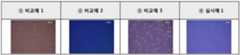
이와 같이, 관찰한 상기 각 저방사 코팅의 표면을 상기 광학 현미경 이미지로 촬영하여 도 5에 나타내었다.
The surface of each of the low-emission coatings thus observed was photographed with the above-mentioned optical microscope image and is shown in Fig.
3. 내습성의 평가3. Evaluation of moisture resistance
실시예 1 및 비교예 1-3의 투명 유리 기재에 코팅된 저방사 코팅에 대해 항온항습 챔버(LS 산전, EBS-35B)를 이용하여, 100℃, 98% RH(습도)의 조건 하에서, 14일 동안 방치하여 내습성을 측정하였다.Under the conditions of 100 ° C and 98% RH (humidity), 14 (light) was applied to the transparent glass substrate coated with the transparent glass substrate of Example 1 and Comparative Example 1-3 using a constant temperature and humidity chamber (LSISON, And the humidity resistance was measured.
측정 방법: 광학 현미경(Nikon, ECLIPSE LV 100) (X200)을 이용하여 부식점의 개수를 측정하였다.Measurement method: The number of corrosion points was measured using an optical microscope (Nikon, ECLIPSE LV 100) (X200).
이와 같이, 내습성 평가 후 부식이 발생된 저방사 코팅의 표면을 상기 광학 현미경 이미지로 촬영하여 도 6에 나타내었다.
Thus, the surface of the low emissivity coating with corrosion after the moisture resistance evaluation was photographed with the above optical microscope image and is shown in Fig.
4. 내화학성 평가4. Chemical resistance evaluation
실시예 1 및 비교예 1-3의 투명 유리 기재에 코팅된 저방사 코팅을 상온에서, pH 2의 시그마 알드리치 HCl 용액에 30분간 침지하여 내화학성을 측정하였다.The low emissivity coating coated on the transparent glass substrate of Example 1 and Comparative Example 1-3 was immersed in a Sigma Aldrich HCl solution of
측정 방법: 분광측색계(제조사 KONICA MINOLTA, 모델명 VTLCM-700)를 이용하여, 침지 전후의 색지수(color index) 변화 값을 측정하였다.Measurement method: A change in color index before and after immersion was measured using a spectrophotometer (KONICA MINOLTA, model name VTLCM-700).
이와 같이, 측정한 색지수 변화 값의 그래프를 도 7에 나타내었고, 내화학성 측정 후 색지수가 변화된 저방사 코팅의 표면을 광학 현미경(Nikon, ECLIPSE LV 100) (X200)으로 촬영하여 도 7에 나타내었다.7 shows a graph of measured change in color index, and the surface of the low-radiated coating having the color index changed after measurement of chemical resistance was photographed with an optical microscope (Nikon, ECLIPSE LV 100) (X200) Respectively.
구체적으로, 도 8의 그래프에서, X축의 색 (T)는 저방사 코팅이 코팅된 투명 유리 기재에 투과되는 색을 나타내고, 색 (R)은 저방사 코팅 면에서 반사되는 색을 나타내고, 색 (S)는 투명 유리 기재 면에서 반사되는 색을 나타내며, Y축의 ΔE=(ΔL2+Δa2 +Δb2)1/2는 색지수 변화 값을 나타낸다.Specifically, in the graph of Fig. 8, the color (T) on the X axis represents the color transmitted through the transparent glass substrate coated with the low radiation coating, the color (R) represents the color reflected from the low radiation coated surface, S) represents the color reflected from the transparent glass substrate surface, and ΔE = (ΔL2 + Δa2 + Δb2 )1/2 on the Y axis represents the color index change value.
5. 내마모성의 평가5. Evaluation of wear resistance
실시예 1 및 비교예 1-3의 투명 유리 기재에 코팅된 저방사 코팅에 대해 강화 시험 이전 및 강화 시험 이후의 내마모성을 각각 측정하였다.The abrasion resistance before and after the strengthening test was measured for the low emissivity coatings coated on the clear glass substrates of Example 1 and Comparative Example 1-3, respectively.
측정 방법: 세척기(MANNA, MGR-460)을 사용하여 내마모성 시험을 실시하였고, 그에 따라 육안으로 상기 각 저방사 코팅의 표면에 스크래치가 발생하였는지 여부를 관찰하고, 상기 각 저방사 코팅의 표면에 스크래치가 발생하기 시작하는데 걸린 시간을 측정하여 기계적 내구성을 평가하였다. 상기 스크래치는 육안으로 관찰시 구분 가능한 최소 크기인 약 50㎛ 이상의 폭을 가지는 것을 관찰하였다.
Measuring method: A wear resistance test was performed using a washing machine (MANNA, MGR-460), and visually observing whether or not scratches occurred on the surface of each low-radiated coating were observed, and scratches And the mechanical durability was evaluated. The scratches were observed to have a width of at least about 50 탆 which is the minimum size that can be distinguished upon visual observation.
6. 단부면(edge face) 부식성의 평가6. Evaluation of edge face corrosion
실시예 1 및 비교예 1-3의 투명 유리 기재에 코팅된 저방사 코팅을 98℃, 100% RH(습도)의 조건 하에서, 14일 동안 방치하여 단부면에서, 저방사층의 부식 깊이를 측정하였다.The low spin coating coated on the transparent glass substrate of Example 1 and Comparative Example 1-3 was allowed to stand for 14 days under the conditions of 98 ° C and 100% RH (humidity) to measure the corrosion depth of the low spinning layer Respectively.
측정 방법: 광학현미경(Nikon, ECLIPSE LV 100) (X200)을 사용하여 단부면의 저방사층의 광학 현미경 이미지를 촬영하고, 저방사층이 부식된 깊이를 측정하였다.
Measurement method: An optical microscope image of the low emissivity layer on the end face was photographed using an optical microscope (Nikon,
(개수)Moisture resistance
(Count)
부식된 깊이(㎛)End
Corrosive depth (㎛)
코팅반사(R): 0.06
유리 반사(S):0.05Permeation (T): 0.09
Coating Reflectance (R): 0.06
Glass reflection (S): 0.05
강화 후: 6분Before reinforcement: 6 minutes
After fortification: 6 minutes
코팅반사(R): 1.77
유리 반사(S):0.98Permeation (T): 0.14
Coating Reflectance (R): 1.77
Glass reflection (S): 0.98
강화 후: 1분Before reinforcement: 5 minutes
After fortification: 1 minute
코팅반사(R): 0.23
유리 반사(S): 0.29Permeation (T): 0.21
Coating Reflectance (R): 0.23
Glass reflection (S): 0.29
강화 후: 5분Before reinforcement: 5 minutes
After fortification: 5 minutes
코팅반사(R): 0.06
유리 반사(S): 0.07Permeation (T): 0.04
Coating Reflectance (R): 0.06
Glass reflection (S): 0.07
강화 후: 1분Before reinforcement: 10 minutes
After fortification: 1
상기 표 1에 나타난 바와 같이, 실시예 1의 저방사 코팅은 부식점의 개수가 2개에 불과하여 내습성이 우수하고, 색지수 변화가 현저히 작아 내화학성이 우수하며, 특히, 고온의 강화 공정을 적용한 이후라도 스크래치가 발생하기 시작하는 시간이 더욱 길어 내열성 및 내마모성 모두가 현저히 우수함을 명확히 확인할 수 있다. 또한, 단부면의 부식 깊이가 80㎛로 현저히 작아 단부면 부식이 효과적으로 감소되었음을 확인할 수 있다.As shown in Table 1, the low-emission coating of Example 1 exhibited excellent resistance to moisture due to only a few corrosion points, and a remarkably small change in color index, which was excellent in chemical resistance. In particular, It can be clearly seen that both the heat resistance and the abrasion resistance are remarkably excellent even when the scratches start to occur even after the application of the scratches. In addition, it can be confirmed that the corrosion depth of the end face is significantly reduced to 80 탆, and the corrosion of the end face is effectively reduced.
반면, 비교예 1의 저방사 코팅은 부식점의 개수가 100배나 증가하여 내습성이 현저히 열등하고, 색지수 변화값이 현저히 커서 내화학성이 열등하며, 고온의 강화 공정을 적용한 이후에는 스크래치가 발생하기 시작하는 시간이 1분 밖에 되지 않아 저방사 코팅이 손상된 것으로 내열성 및 내마모성이 열등함을 확인할 수 있다. 게다가, 단부면의 부식 깊이가 100배나 증가하여 단부면에서 부식이 현저히 발생하였음을 확인할 수 있다.On the other hand, in the low spin coating of Comparative Example 1, the number of corrosion points increased by a factor of 100, the moisture resistance was remarkably inferior, the color index change value was remarkably large and the chemical resistance was inferior, and after the high temperature tempering process was applied, It is found that the low-radiation coating is damaged because the time for starting to start is only one minute, which is inferior in heat resistance and abrasion resistance. In addition, the corrosion depth on the end face increased by 100 times, indicating that the corrosion occurred remarkably on the end face.
또한, 비교예 2의 저방사 코팅은 내마모성은 강화 전후로 5분 정도로 측정되어 양호하나, 부식점의 개수가 60개로 내습성이 열등하고, 색지수 변화 값이 커서 내화학성이 열등하다. 게다가, 단부면의 부식 깊이가 깊어 부식이 현저히 발생하였음을 확인할 수 있다.In addition, the low spin coating of Comparative Example 2 has good anti-abrasion properties measured at about 5 minutes before and after strengthening, but the number of corrosion points is 60, which is inferior in moisture resistance and has a large change in color index, which is inferior in chemical resistance. In addition, it can be seen that the corrosion depth on the end face is deep and the corrosion has remarkably occurred.
또한, 비교예 3의 저방사 코팅은 부식점의 개수가 5개로 내습성이 양호하고, 색지수 변화 값이 작아 내화학성은 우수하나, 고온의 강화 공정을 적용한 이후에는 스크래치가 발생하기 시작하는 시간이 1분 밖에 되지 않아 실시예 1에 비해 1/6에 해당하는 값이므로 저방사 코팅이 현저히 손상되어 내열성 및 내마모성이 현저히 열등함을 확인할 수 있다. 게다가, 단부면의 부식 깊이가 100㎛로 저방사 코팅의 손상에 의해 단부면의 부식이 더욱 촉진되었음을 확인할 수 있다.
In addition, the low spin coating of Comparative Example 3 had five corrosion points with good moisture resistance and a small change in color index, which is excellent in chemical resistance. However, after application of a high temperature tempering process, Is only one minute, which is a value corresponding to 1/6 of that of Example 1, so that the low radiation coating is remarkably damaged and the heat resistance and abrasion resistance are remarkably inferior. In addition, it can be confirmed that the corrosion depth of the end face is 100 μm, and the corrosion of the end face is further promoted by the damage of the low radiation coating.
100, 200, 300: 저방사 코팅
400: 저방사 유리
110: 제1유전체층
120: 제2 유전체층
130: 저방사층
140: 배리어층
150: 보호층
151: 금속층
152: 금속 산화물층
153: 실리콘계 또는 지르코늄계 복합금속 산화질화물층
160: 기재100, 200, 300: low radiation coating
400: low emission glass
110: first dielectric layer
120: second dielectric layer
130: low radiation layer
140: barrier layer
150: protective layer
151: metal layer
152: metal oxide layer
153: a silicon-based or zirconium-based composite metal oxynitride layer
160: substrate
Claims (18)
Translated fromKorean상기 제1유전체층의 굴절률이 상기 제2유전체층의 굴절률 보다 높은 저방사 코팅.
Sequentially, a first dielectric layer comprising silicon aluminum nitride; Low radiation layer; And a second dielectric layer comprising silicon aluminum nitride,
Wherein the refractive index of the first dielectric layer is higher than the refractive index of the second dielectric layer.
상기 제1유전체층은 굴절률이 550nm의 파장에서 2.1 내지 2.3인
저방사 코팅.
The method according to claim 1,
Wherein the first dielectric layer has a refractive index of 2.1 to 2.3 at a wavelength of 550 nm
Low radiation coating.
상기 제2유전체층은 굴절률이 550nm의 파장에서 1.8 내지 2.0인
저방사 코팅.
The method according to claim 1,
Wherein the second dielectric layer has a refractive index of 1.8 to 2.0 at a wavelength of 550 nm
Low radiation coating.
상기 제1유전체층은 스퍼터링 타겟(sputtering target)으로서 실리콘알루미늄을 아르곤 가스 대 질소 가스의 유량비가 5:1 내지 8:1인 반응성 가스 분위기 하에서 증착하여 형성한
저방사 코팅.
The method according to claim 1,
The first dielectric layer is formed by depositing silicon aluminum as a sputtering target in a reactive gas atmosphere having a flow ratio of argon gas to nitrogen gas of 5: 1 to 8: 1
Low radiation coating.
상기 제2유전체층은 스퍼터링 타겟(sputtering target)으로서 실리콘알루미늄을 아르곤 가스 대 질소 가스의 유량비가 1:1 내지 4:1인 반응성 가스 분위기 하에서 증착하여 형성한
저방사 코팅.
The method according to claim 1,
The second dielectric layer is formed by depositing silicon aluminum as a sputtering target in a reactive gas atmosphere having a flow ratio of argon gas to nitrogen gas of 1: 1 to 4: 1
Low radiation coating.
상기 제1유전체층의 두께가 20nm 내지 60nm인
저방사 코팅.
The method according to claim 1,
Wherein the first dielectric layer has a thickness of 20 nm to 60 nm
Low radiation coating.
상기 제2유전체층의 두께가 20nm 내지 60nm인
저방사 코팅.
The method according to claim 1,
Wherein the second dielectric layer has a thickness of 20 nm to 60 nm
Low radiation coating.
상기 저방사층의 적어도 일면에 접하여 적층된 배리어층을 더 포함하고, 상기 배리어층이 금속을 포함하면서 금속 산화물을 포함하지 않는
저방사 코팅.
The method according to claim 1,
Further comprising a barrier layer laminated on at least one side of the low-emission layer, wherein the barrier layer includes a metal and does not include a metal oxide
Low radiation coating.
상기 배리어층이 니켈(Ni), 크롬(Cr), 니오븀(Nb), 니켈-크롬(Ni-Cr), 티타늄(Ti), 니켈티티늄(Ni-Ti) 및 이들의 조합으로 이루어진 군에서 선택된 적어도 하나를 포함하는 금속을 포함하는
저방사 코팅.
9. The method of claim 8,
Wherein the barrier layer is selected from the group consisting of Ni, Cr, Nb, Ni-Cr, Ti, Ni-Ti, Comprising at least one metal
Low radiation coating.
상기 배리어층의 두께가 0.5nm 내지 3.0nm인
저방사 코팅.
9. The method of claim 8,
Wherein the barrier layer has a thickness of 0.5 nm to 3.0 nm
Low radiation coating.
상기 제2유전체층의 상부에 금속층; 금속 산화물층; 및 실리콘계 또는 지르코늄계 복합금속 산화질화물층;을 순차적으로 포함하는 다층 구조의 보호층을 더 포함하는
저방사 코팅.
The method according to claim 1,
A metal layer on the second dielectric layer; A metal oxide layer; And a silicon-based or zirconium-based composite metal oxynitride layer,
Low radiation coating.
상기 금속층은 실리콘, 알루미늄, 티타늄, 지르코늄, 실리콘계 복합금속, 티타늄계 복합금속, 지르코늄계 복합금속 및 이들의 조합으로부터 선택된 적어도 하나를 포함하고, 두께가 0.5nm 내지 5nm인
저방사 코팅.
12. The method of claim 11,
Wherein the metal layer comprises at least one selected from the group consisting of silicon, aluminum, titanium, zirconium, a silicon based composite metal, a titanium based composite metal, a zirconium based composite metal and combinations thereof,
Low radiation coating.
상기 금속 산화물층은 실리콘 산화물, 알루미늄 산화물, 티타늄 산화물, 지르코늄 산화물, 실리콘계 복합금속 산화물, 티타늄계 복합금속 산화물, 지르코늄계 복합금속 산화물 및 이들의 조합으로부터 선택된 적어도 하나를 포함하고, 두께가 0.5nm 내지 5nm인
저방사 코팅.
12. The method of claim 11,
Wherein the metal oxide layer contains at least one selected from the group consisting of silicon oxide, aluminum oxide, titanium oxide, zirconium oxide, silicon based composite metal oxide, titanium based composite metal oxide, zirconium based composite metal oxide and combinations thereof, 5 nm
Low radiation coating.
상기 실리콘계 또는 지르코늄계 복합금속 산화질화물층의 두께는 2nm 내지 20nm인
저방사 코팅.
12. The method of claim 11,
The thickness of the silicon-based or zirconium-based composite metal oxynitride layer is preferably from 2 nm to 20 nm
Low radiation coating.
상기 저방사층은 Ag, Au, Cu, Al, Pt, Pd 및 이들의 조합으로 이루어진 군에서 선택된 적어도 하나를 포함하는
저방사 코팅.
The method according to claim 1,
Wherein the low-emission layer comprises at least one selected from the group consisting of Ag, Au, Cu, Al, Pt, Pd,
Low radiation coating.
상기 저방사층의 두께는 5nm 내지 25nm인
저방사 코팅.
The method according to claim 1,
The thickness of the low-emission layer is in the range of 5 nm to 25 nm
Low radiation coating.
Transparent substrate; And a low emissivity coating according to any one of claims 1 to 14 coated on at least one side of the transparent substrate.
상기 투명 기재는 80% 내지 100%의 가시광선 투과율을 갖는 유리 또는 투명 플라스틱 기판인
창호용 기능성 건축 자재.
16. The method of claim 15,
The transparent substrate may be a glass or transparent plastic substrate having a visible light transmittance of 80% to 100%
Functional building materials for windows.
Applications Claiming Priority (2)
| Application Number | Priority Date | Filing Date | Title |
|---|---|---|---|
| KR20140089619 | 2014-07-16 | ||
| KR1020140089619 | 2014-07-16 |
Publications (2)
| Publication Number | Publication Date |
|---|---|
| KR20160010332Atrue KR20160010332A (en) | 2016-01-27 |
| KR101979625B1 KR101979625B1 (en) | 2019-05-20 |
Family
ID=55309564
Family Applications (1)
| Application Number | Title | Priority Date | Filing Date |
|---|---|---|---|
| KR1020150099652AActiveKR101979625B1 (en) | 2014-07-16 | 2015-07-14 | Low-emissivity coat and functional building material including low-emissivity coat for windows |
Country Status (1)
| Country | Link |
|---|---|
| KR (1) | KR101979625B1 (en) |
Cited By (6)
| Publication number | Priority date | Publication date | Assignee | Title |
|---|---|---|---|---|
| KR20170032530A (en)* | 2015-09-14 | 2017-03-23 | (주)엘지하우시스 | Functional building material including low-emissivity coat for windows |
| KR20180027062A (en)* | 2016-09-06 | 2018-03-14 | (주)엘지하우시스 | Functional building material including low-emissivity coat for windows |
| WO2018151485A1 (en)* | 2017-02-17 | 2018-08-23 | 주식회사 케이씨씨 | Reflective coating substrate |
| WO2019050193A1 (en)* | 2017-09-08 | 2019-03-14 | (주)엘지하우시스 | Functional building material for door and window |
| WO2019112320A1 (en)* | 2017-12-06 | 2019-06-13 | (주)엘지하우시스 | Functional building material for windows and doors |
| KR20200107920A (en)* | 2020-09-10 | 2020-09-16 | (주)엘지하우시스 | Functional building material including low-emissivity coat for windows |
Families Citing this family (1)
| Publication number | Priority date | Publication date | Assignee | Title |
|---|---|---|---|---|
| KR102759137B1 (en) | 2023-02-06 | 2025-01-24 | 주식회사 케이씨씨글라스 | Laminate for low-emissivity glass |
Citations (4)
| Publication number | Priority date | Publication date | Assignee | Title |
|---|---|---|---|---|
| JP2006248871A (en)* | 2005-03-14 | 2006-09-21 | Nippon Electric Glass Co Ltd | Peep window member, and its production method |
| KR20090099364A (en)* | 2008-03-17 | 2009-09-22 | 주식회사 케이씨씨 | Heat-resistant low-spinning glass with excellent durability and manufacturing method |
| KR20100097175A (en)* | 2007-11-23 | 2010-09-02 | 에이지씨 플랫 글래스 노스 아메리카, 인코퍼레이티드 | Low emissivity coating with low solar heat gain coefficient, enhanced chemical and mechanical properties and method of making the same |
| KR20130020029A (en)* | 2011-08-18 | 2013-02-27 | (주)엘지하우시스 | Temperable low-emissivity glass and method for preparing thereof |
- 2015
- 2015-07-14KRKR1020150099652Apatent/KR101979625B1/enactiveActive
Patent Citations (4)
| Publication number | Priority date | Publication date | Assignee | Title |
|---|---|---|---|---|
| JP2006248871A (en)* | 2005-03-14 | 2006-09-21 | Nippon Electric Glass Co Ltd | Peep window member, and its production method |
| KR20100097175A (en)* | 2007-11-23 | 2010-09-02 | 에이지씨 플랫 글래스 노스 아메리카, 인코퍼레이티드 | Low emissivity coating with low solar heat gain coefficient, enhanced chemical and mechanical properties and method of making the same |
| KR20090099364A (en)* | 2008-03-17 | 2009-09-22 | 주식회사 케이씨씨 | Heat-resistant low-spinning glass with excellent durability and manufacturing method |
| KR20130020029A (en)* | 2011-08-18 | 2013-02-27 | (주)엘지하우시스 | Temperable low-emissivity glass and method for preparing thereof |
Cited By (14)
| Publication number | Priority date | Publication date | Assignee | Title |
|---|---|---|---|---|
| US10287208B2 (en) | 2015-09-14 | 2019-05-14 | Lg Hausys, Ltd. | Functional building material for windows and doors |
| KR20170032530A (en)* | 2015-09-14 | 2017-03-23 | (주)엘지하우시스 | Functional building material including low-emissivity coat for windows |
| KR20180027062A (en)* | 2016-09-06 | 2018-03-14 | (주)엘지하우시스 | Functional building material including low-emissivity coat for windows |
| WO2018048034A1 (en)* | 2016-09-06 | 2018-03-15 | (주)엘지하우시스 | Functional building material for windows and doors |
| US11105966B2 (en) | 2016-09-06 | 2021-08-31 | Lg Hausys, Ltd. | Functional building material for windows and doors |
| WO2018151485A1 (en)* | 2017-02-17 | 2018-08-23 | 주식회사 케이씨씨 | Reflective coating substrate |
| CN110249072A (en)* | 2017-02-17 | 2019-09-17 | Kcc公司 | Reflective coating film substrate |
| KR20180095217A (en)* | 2017-02-17 | 2018-08-27 | 주식회사 케이씨씨 | Reflective Coated Substrate |
| WO2019050193A1 (en)* | 2017-09-08 | 2019-03-14 | (주)엘지하우시스 | Functional building material for door and window |
| US11345631B2 (en) | 2017-09-08 | 2022-05-31 | Lg Hausys, Ltd. | Functional building material for door and window |
| WO2019112320A1 (en)* | 2017-12-06 | 2019-06-13 | (주)엘지하우시스 | Functional building material for windows and doors |
| KR20190067030A (en)* | 2017-12-06 | 2019-06-14 | (주)엘지하우시스 | Functional building material including low-emissivity coat for windows |
| US11161780B2 (en) | 2017-12-06 | 2021-11-02 | Lg Hausys, Ltd. | Functional building material for windows and doors |
| KR20200107920A (en)* | 2020-09-10 | 2020-09-16 | (주)엘지하우시스 | Functional building material including low-emissivity coat for windows |
Also Published As
| Publication number | Publication date |
|---|---|
| KR101979625B1 (en) | 2019-05-20 |
Similar Documents
| Publication | Publication Date | Title |
|---|---|---|
| KR101979625B1 (en) | Low-emissivity coat and functional building material including low-emissivity coat for windows | |
| KR101335169B1 (en) | Low emissivity coating with low solar heat gain coefficient, enhanced chemical and mechanical properties and method of making the same | |
| CN101925552B (en) | Low emissivity coating with low solar heat gain coefficient, enhanced chemical and mechanical properties and method of production | |
| JP6408565B2 (en) | Low emissivity and anti-sun glazing | |
| JP5681100B2 (en) | Glazing provided with a laminate consisting of multiple thin layers | |
| KR101788369B1 (en) | Low-emissivity coating film, method for preparing the same and functional building material for windows comprising the same | |
| KR101788368B1 (en) | Low-emissivity coating film, method for preparing the same and functional building material for windows comprising the same | |
| KR101873103B1 (en) | Functional building material including low-emissivity coat for windows | |
| KR101768257B1 (en) | Low-emissivity coat and building material for window including the same | |
| BR112015029941B1 (en) | LOW-EMISSIVITY ANTI-SOLAR COATING | |
| KR102157540B1 (en) | Functional building material including low-emissivity coat for windows | |
| EP3351717B1 (en) | Functional building material for windows and doors | |
| KR101972364B1 (en) | Low-emissivity coat and functional building material including low-emissivity coat for windows | |
| KR101970495B1 (en) | Low-emissivity coat, method for preparing low-emissivity coat and functional building material including low-emissivity coat for windows | |
| KR102787509B1 (en) | TRANSPARENT SUBSTRATE WITH A MULTILAYER THIN FILM coating AND MULTYPLE GLAZING UNIT COMPRISING THE SAME | |
| KR102190680B1 (en) | Functional building material including low-emissivity coat for windows | |
| KR102001993B1 (en) | Low-emissivity coat, method for preparing low-emissivity coat and functional building material including low-emissivity coat for windows | |
| KR102715243B1 (en) | Functional building material including low-emissivity coat for windows | |
| KR20230166373A (en) | TRANSPARENT SUBSTRATE WITH A MULTILAYER THIN FILM coating AND MULTYPLE GLAZING UNIT COMPRISING THE SAME | |
| HK1152289B (en) | Low emissivity coating with low solar heat gain coefficient, enhanced chemical and mechanical properties and method of making the same |
Legal Events
| Date | Code | Title | Description |
|---|---|---|---|
| PA0109 | Patent application | Patent event code:PA01091R01D Comment text:Patent Application Patent event date:20150714 | |
| PG1501 | Laying open of application | ||
| A201 | Request for examination | ||
| PA0201 | Request for examination | Patent event code:PA02012R01D Patent event date:20170721 Comment text:Request for Examination of Application Patent event code:PA02011R01I Patent event date:20150714 Comment text:Patent Application | |
| E902 | Notification of reason for refusal | ||
| PE0902 | Notice of grounds for rejection | Comment text:Notification of reason for refusal Patent event date:20181026 Patent event code:PE09021S01D | |
| E701 | Decision to grant or registration of patent right | ||
| PE0701 | Decision of registration | Patent event code:PE07011S01D Comment text:Decision to Grant Registration Patent event date:20190411 | |
| GRNT | Written decision to grant | ||
| PR0701 | Registration of establishment | Comment text:Registration of Establishment Patent event date:20190513 Patent event code:PR07011E01D | |
| PR1002 | Payment of registration fee | Payment date:20190513 End annual number:3 Start annual number:1 | |
| PG1601 | Publication of registration | ||
| PR1001 | Payment of annual fee | Payment date:20220310 Start annual number:4 End annual number:4 | |
| PR1001 | Payment of annual fee | Payment date:20230306 Start annual number:5 End annual number:5 | |
| PR1001 | Payment of annual fee | Payment date:20240305 Start annual number:6 End annual number:6 |