KR20150146477A - Water treating apparatus including bubble generator - Google Patents
Water treating apparatus including bubble generatorDownload PDFInfo
- Publication number
- KR20150146477A KR20150146477AKR1020150176223AKR20150176223AKR20150146477AKR 20150146477 AKR20150146477 AKR 20150146477AKR 1020150176223 AKR1020150176223 AKR 1020150176223AKR 20150176223 AKR20150176223 AKR 20150176223AKR 20150146477 AKR20150146477 AKR 20150146477A
- Authority
- KR
- South Korea
- Prior art keywords
- raw water
- water
- water tank
- bubble generator
- membrane
- Prior art date
- Legal status (The legal status is an assumption and is not a legal conclusion. Google has not performed a legal analysis and makes no representation as to the accuracy of the status listed.)
- Granted
Links
- XLYOFNOQVPJJNP-UHFFFAOYSA-NwaterSubstancesOXLYOFNOQVPJJNP-UHFFFAOYSA-N0.000titleclaimsabstractdescription164
- 238000005374membrane filtrationMethods0.000claimsabstractdescription31
- 238000001914filtrationMethods0.000claimsabstractdescription21
- 239000012528membraneSubstances0.000claimsdescription14
- 239000007788liquidSubstances0.000claimsdescription12
- 238000000034methodMethods0.000claimsdescription11
- 239000011368organic materialSubstances0.000claimsdescription9
- 238000001223reverse osmosisMethods0.000claimsdescription9
- 239000000126substanceSubstances0.000claimsdescription8
- 239000002245particleSubstances0.000claimsdescription5
- 238000004065wastewater treatmentMethods0.000claimsdescription5
- 238000001471micro-filtrationMethods0.000claimsdescription4
- 238000000108ultra-filtrationMethods0.000claimsdescription4
- 230000001590oxidative effectEffects0.000claimsdescription2
- 239000000706filtrateSubstances0.000claims1
- 238000007599dischargingMethods0.000abstractdescription2
- 239000005416organic matterSubstances0.000description11
- 238000004140cleaningMethods0.000description5
- 239000012047saturated solutionSubstances0.000description4
- 238000010586diagramMethods0.000description3
- 239000008235industrial waterSubstances0.000description3
- 230000004931aggregating effectEffects0.000description2
- 238000011109contaminationMethods0.000description2
- 238000000354decomposition reactionMethods0.000description2
- 238000012423maintenanceMethods0.000description2
- 239000010865sewageSubstances0.000description2
- 239000007787solidSubstances0.000description2
- 235000013361beverageNutrition0.000description1
- 238000006243chemical reactionMethods0.000description1
- 239000003795chemical substances by applicationSubstances0.000description1
- 238000005660chlorination reactionMethods0.000description1
- 239000000701coagulantSubstances0.000description1
- 238000005345coagulationMethods0.000description1
- 230000015271coagulationEffects0.000description1
- 239000000470constituentSubstances0.000description1
- 230000000694effectsEffects0.000description1
- 239000003344environmental pollutantSubstances0.000description1
- 239000010419fine particleSubstances0.000description1
- 239000012530fluidSubstances0.000description1
- 239000003673groundwaterSubstances0.000description1
- 238000009285membrane foulingMethods0.000description1
- 239000002101nanobubbleSubstances0.000description1
- 231100000719pollutantToxicity0.000description1
- 230000001376precipitating effectEffects0.000description1
- 238000001556precipitationMethods0.000description1
- 238000000746purificationMethods0.000description1
- 230000001105regulatory effectEffects0.000description1
- 229920006395saturated elastomerPolymers0.000description1
- 230000001932seasonal effectEffects0.000description1
- 238000004904shorteningMethods0.000description1
- 239000000243solutionSubstances0.000description1
- 238000001179sorption measurementMethods0.000description1
- 238000005406washingMethods0.000description1
Images

Classifications
- B—PERFORMING OPERATIONS; TRANSPORTING
- B01—PHYSICAL OR CHEMICAL PROCESSES OR APPARATUS IN GENERAL
- B01D—SEPARATION
- B01D65/00—Accessories or auxiliary operations, in general, for separation processes or apparatus using semi-permeable membranes
- B01D65/08—Prevention of membrane fouling or of concentration polarisation
- B—PERFORMING OPERATIONS; TRANSPORTING
- B01—PHYSICAL OR CHEMICAL PROCESSES OR APPARATUS IN GENERAL
- B01D—SEPARATION
- B01D61/00—Processes of separation using semi-permeable membranes, e.g. dialysis, osmosis or ultrafiltration; Apparatus, accessories or auxiliary operations specially adapted therefor
- B01D61/02—Reverse osmosis; Hyperfiltration ; Nanofiltration
- B01D61/025—Reverse osmosis; Hyperfiltration
- B—PERFORMING OPERATIONS; TRANSPORTING
- B01—PHYSICAL OR CHEMICAL PROCESSES OR APPARATUS IN GENERAL
- B01D—SEPARATION
- B01D61/00—Processes of separation using semi-permeable membranes, e.g. dialysis, osmosis or ultrafiltration; Apparatus, accessories or auxiliary operations specially adapted therefor
- B01D61/14—Ultrafiltration; Microfiltration
- B01D61/145—Ultrafiltration
- B—PERFORMING OPERATIONS; TRANSPORTING
- B01—PHYSICAL OR CHEMICAL PROCESSES OR APPARATUS IN GENERAL
- B01D—SEPARATION
- B01D61/00—Processes of separation using semi-permeable membranes, e.g. dialysis, osmosis or ultrafiltration; Apparatus, accessories or auxiliary operations specially adapted therefor
- B01D61/14—Ultrafiltration; Microfiltration
- B01D61/147—Microfiltration
- B—PERFORMING OPERATIONS; TRANSPORTING
- B01—PHYSICAL OR CHEMICAL PROCESSES OR APPARATUS IN GENERAL
- B01D—SEPARATION
- B01D63/00—Apparatus in general for separation processes using semi-permeable membranes
- B—PERFORMING OPERATIONS; TRANSPORTING
- B01—PHYSICAL OR CHEMICAL PROCESSES OR APPARATUS IN GENERAL
- B01D—SEPARATION
- B01D65/00—Accessories or auxiliary operations, in general, for separation processes or apparatus using semi-permeable membranes
- B01D65/02—Membrane cleaning or sterilisation ; Membrane regeneration
- B01F3/04248—
- C—CHEMISTRY; METALLURGY
- C02—TREATMENT OF WATER, WASTE WATER, SEWAGE, OR SLUDGE
- C02F—TREATMENT OF WATER, WASTE WATER, SEWAGE, OR SLUDGE
- C02F1/00—Treatment of water, waste water, or sewage
- C02F1/44—Treatment of water, waste water, or sewage by dialysis, osmosis or reverse osmosis
- C02F1/441—Treatment of water, waste water, or sewage by dialysis, osmosis or reverse osmosis by reverse osmosis
- C—CHEMISTRY; METALLURGY
- C02—TREATMENT OF WATER, WASTE WATER, SEWAGE, OR SLUDGE
- C02F—TREATMENT OF WATER, WASTE WATER, SEWAGE, OR SLUDGE
- C02F1/00—Treatment of water, waste water, or sewage
- C02F1/44—Treatment of water, waste water, or sewage by dialysis, osmosis or reverse osmosis
- C02F1/444—Treatment of water, waste water, or sewage by dialysis, osmosis or reverse osmosis by ultrafiltration or microfiltration
- C—CHEMISTRY; METALLURGY
- C02—TREATMENT OF WATER, WASTE WATER, SEWAGE, OR SLUDGE
- C02F—TREATMENT OF WATER, WASTE WATER, SEWAGE, OR SLUDGE
- C02F1/00—Treatment of water, waste water, or sewage
- C02F1/72—Treatment of water, waste water, or sewage by oxidation
- C02F1/74—Treatment of water, waste water, or sewage by oxidation with air
- B01F2215/0052—
Landscapes
- Chemical & Material Sciences (AREA)
- Engineering & Computer Science (AREA)
- Water Supply & Treatment (AREA)
- Chemical Kinetics & Catalysis (AREA)
- Life Sciences & Earth Sciences (AREA)
- Hydrology & Water Resources (AREA)
- Environmental & Geological Engineering (AREA)
- Organic Chemistry (AREA)
- Nanotechnology (AREA)
- Separation Using Semi-Permeable Membranes (AREA)
Abstract
Translated fromKoreanDescription
Translated fromKorean본 발명은 기포 발생기를 포함하는 수처리장치에 관한 것으로서, 보다 구체적으로는 기포를 발생시키는 기포 발생기를 이용하여 처리수수에 포함된 오염물질을 저감하기 위한 장치에 관한 것이다.BACKGROUND OF THE INVENTION 1. Field of the Invention The present invention relates to a water treatment apparatus including a bubble generator, and more particularly, to an apparatus for reducing pollutants contained in treated water using a bubble generator that generates bubbles.
수처리장치는 원수를 의도한 목적에 적합하도록 처리하는 장치로서, 크게 분류하면 용수처리장치와 폐수처리장치가 있다. 여기서, 전자는 음료수나 공업용수를 대상으로 하고 후자는 도시하수 또는 도시폐수를 대상으로 한다.A water treatment apparatus is a device that treats raw water to an intended purpose and roughly classified into a water treatment apparatus and a wastewater treatment apparatus. Here, the former targets beverages or industrial water, and the latter targets municipal sewage or city sewage.
이러한 수처리장치는 침전, 화학, 응집, 여과, 흡착, 생물학적처리 및 염소처리 등의 방법을 활용하여 원수를 의도한 수준으로 처리하게 되며, 각각의 용도에 따라서 사용되는 처리방법에는 차이가 있게 된다.Such a water treatment apparatus treats raw water to an intended level by using methods such as precipitation, chemical, coagulation, filtration, adsorption, biological treatment, and chlorination, and there is a difference in treatment methods used depending on each application.
일 예로서 생물학적 처리장의 처리수를 원수로서 이용하는 멤브레인 재이용시설은 주로 공업용수를 공급하기 위한 목적으로 사용되며, 일반적인 수원(지하수, 호소수, 하천수 등)에 비해 일반적으로 용존성 유기물(COD, TOC 등) 유기물함량이 상대적으로 많은 특징을 가지고 있다. 즉, 생물학적 처리장의 처리수를 원수로 이용하는 경우 처리장 공정 운영 및 계절적 영향 등으로 원수내 수질이 일정치 않은 특징이 있다.As an example, a membrane reuse facility using treated water from a biological treatment plant as raw water is mainly used for supplying industrial water, and is generally used for dissolving organics (COD, TOC, etc.) compared with general water sources (groundwater, lake water, ) Organic matter content is relatively high. That is, when the treated water of the biological treatment plant is used as the raw water, the water quality in the raw water is unstable due to the operation of the treatment plant and seasonal influences.
이러한 생물학적 처리장의 경우 법적방류수질 규제항목인 BOD, COD, SS 등에 대해서만 관리가 이루어지기 때문에, 탁도, 용존성 유기물질 항목 DOC, TOC 등이 일정하지 않은 특성이 있다. 따라서, 원수수질이 일정치 않으면 재이용시설의 안정적인 운영 및 유지관리가 용이치 않으며, 이로 인해 멤브레인 파울링(Fouling)의 빈도가 늘어나게 되며, 그에 따라 세정횟수가 많아져 결과적으로 유지관리비 상승 및 멤브레인 수명단축을 야기시킨다.In this biological treatment plant, only the BOD, COD, and SS, which are regulated by the legal discharge water quality regulations, are managed, and therefore turbidity, DOC and TOC are not constant. Therefore, if the water quality of the raw water is unstable, stable operation and maintenance of the reuse facility is not possible, which increases the frequency of membrane fouling, thereby increasing the number of rinsing, resulting in increased maintenance cost and membrane lifetime Causing shortening.
이러한 파울링은 주로 원수 내에 잔류하는 용존 유기물질에 의해 야기된다. 이를 해소하기 위한 방법으로서 원수 내에 응집제를 첨가하여 유기물질을 응집시킨 후 침전시켜 제거하여 멤브레인으로 유입되는 유기물의 양을 줄이는 방법을 사용할 수 있다. 그러나, 응집제를 효율적으로 사용하기 위해서는 유기물질의 농도에 맞는 적정량의 응집제를 투여하여야만 유기물질이 효율적으로 제거될 뿐만 아니라, 응집제로 인한 추가 경비를 최소화할 수 있다. 문제는, 상술한 바와 같이 원수내 유기물질 농도가 일정치 않기 때문에 적정 응집제 투여량 산정이 불가능하여 또 다른 막 파울링의 원인으로 작용하기도 한다.This fouling is mainly caused by dissolved organic materials remaining in the raw water. As a method for solving this, a method of adding an aggregating agent in the raw water, aggregating the organic material, precipitating and removing the organic material to reduce the amount of the organic material flowing into the membrane can be used. However, in order to efficiently use the flocculant, the proper amount of the flocculant suited to the concentration of the organic material is not only efficiently removed, but also minimizes the additional expense due to the flocculant. The problem is that since the concentration of the organic substance in the raw water is not constant as described above, it is impossible to calculate the proper amount of the coagulant, which is also the cause of another film fouling.
본 발명은 상기와 같은 종래기술의 단점을 극복하기 위해 안출된 것으로서, 멤브레인으로 유입되는 원수 내에 포함된 유기물을 사전에 제거함으로서 세정주기를 늘릴 수 있는 수처리장치를 제공하는 것을 기술적 과제로 삼고 있다.Disclosure of Invention Technical Problem [8] Accordingly, the present invention has been made in view of the above problems, and it is an object of the present invention to provide a water treatment apparatus capable of increasing the cleaning cycle by previously removing organic matters contained in raw water flowing into a membrane.
상기와 같은 기술적 과제를 달성하기 위한 본 발명의 일측면에 의하면, 유입된 원수를 저장하는 원수조; 상기 원수조로부터 공급된 원수를 여과수 및 농축수로 분리하여 배출하는 막여과 모듈; 상기 막여과 모듈로부터 배출된 농축수를 상기 막여과 모듈의 원수 공급측으로 재공급하는 농축수 순환수단; 및 상기 농축수 순환수단 내에 존재하는 원수 내에 기포를 생성하는 기포발생기;를 포함하는 수처리장치가 제공된다.According to an aspect of the present invention, there is provided a washing machine comprising: a raw water tank for storing raw water; A membrane filtration module for separating and discharging the raw water supplied from the raw water tank by filtration water and concentrated water; A concentrated water circulating means for re-supplying the concentrated water discharged from the membrane filtration module to the raw water supply side of the membrane filtration module; And a bubble generator for generating bubbles in the raw water present in the concentrated water circulation means.
여기서, 상기 농축수 순환수단은 상기 막여과 모듈과 상기 원수조 사이에서 연장되는 농축수 배출관을 포함하고, 상기 기포발생기는 상기 농축수 배출관 내부에 기포를 생성할 수 있다.Here, the concentrated water circulation means includes a concentrated water discharge pipe extending between the membrane filtration module and the raw water tank, and the bubble generator may generate bubbles in the concentrated water discharge pipe.
그리고, 상기 농축수 배출관에는 추가적인 여과수단이 구비되고, 상기 여과수단은 상기 기포발생기의 하류측에 배치될 수 있다.Further, the concentrated water discharge pipe may be provided with additional filtration means, and the filtration means may be disposed on the downstream side of the bubble generator.
또한, 상기 기포발생기에 의해 생성되는 기포의 평균입경이 50㎛ 이하일 수 있다.The average particle diameter of the bubbles generated by the bubble generator may be 50 탆 or less.
그리고, 상기 원수조로 유입되는 원수는 생물학적 처리장으로부터 공급되는 처리수일 수 있다.The raw water flowing into the raw water tank may be a treated water supplied from a biological treatment plant.
또한, 상기 막여과 모듈은 가압식 정밀여과막(Microfiltration Membrane, MF) 또는 한외여과막(Ultrafiltration Membrane, UF)일 수 있다.The membrane filtration module may be a microfiltration membrane (MF) or an ultrafiltration membrane (UF).
또한, 상기 막여과 모듈로부터 공급되는 여과수를 추가적으로 처리하는 역삼투 모듈을 더 포함할 수 있다.The apparatus may further include a reverse osmosis module for further processing the filtered water supplied from the membrane filtration module.
또한, 상기 기포발생기는 액체 유입구, 기체 유입구 및 배출구가 형성되는 케이싱; 및 상기 케이싱 내에 구비되어 유입된 액체 및 기체를 가압하는 임펠러;를 포함할 수 있다.The bubble generator may further include: a casing having a liquid inlet, a gas inlet, and an outlet; And an impeller provided in the casing to press the introduced liquid and gas.
또한, 상기 원수조 내에 기포발생기가 추가적으로 구비될 수 있다.In addition, a bubble generator may be additionally provided in the raw water tank.
상기와 같은 구성을 포함하는 본 발명의 일측면에 의하면, 막여과 모듈로 유입되는 원수에 포함된 유기물의 일부를 상기 기포발생기에 의해 제공된 기포를 이용하여 제거함으로써, 파울링의 생성빈도를 낮출 수 있어 세정주기를 연장할 수 있게 된다. 특히, 막여과 모듈로 공급되는 원수가 아니라 막여과 모듈로부터 배출된 농축수에 기포를 제공하므로, 기포와 유기물이 접촉하는 빈도를 증가시켜서 보다 효율적으로 유기물을 제거할 수 있게 된다.According to an aspect of the present invention, the bubbles generated by the bubble generator are used to remove a part of the organic matter contained in the raw water flowing into the membrane filtration module, thereby reducing the frequency of fouling So that the cleaning cycle can be extended. In particular, since the bubbles are supplied to the concentrated water discharged from the membrane filtration module, not the raw water supplied to the membrane filtration module, the frequency of contact between the bubbles and the organic matter is increased, and the organic matter can be removed more efficiently.
그리고, 상기 농축수 순환수단 내에 추가적인 여과수단을 제공하여, 기포와의 접촉으로 유기물을 제거한 후 생기는 스캠이 원수조에 유입되는 것을 차단함으로써, 원수의 추가적인 오염을 방지할 수 있게 된다.Further, additional filtration means is provided in the concentrated water circulation means to prevent the scum generated after the organic matter is removed by contact with the bubbles from flowing into the raw water tank, thereby preventing further contamination of the raw water.
아울러, 상기 기포발생기에 의해 제공되는 기포의 평균입경을 50㎛ 이하로 함으로써, 기포와 유기물의 접촉 정도를 더욱 향상시킬 수 있게 된다.Further, by setting the average particle diameter of the bubbles provided by the bubble generator to be 50 탆 or less, the degree of contact between the bubbles and the organic matter can be further improved.
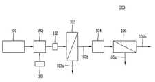
도 1은 본 발명에 따른 수처리장치의 제1 실시예를 개략적으로 도시한 블럭도이다.
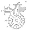
도 2는 상기 제1 실시예에 구비되는 기포발생기의 일 예를 개략적으로 도시한 단면도이다.
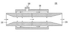
도 3은 상기 제1 실시예에 구비되는 기포발생기의 다른 예를 개략적으로 도시한 단면도이다.
도 4는 본 발명에 따른 수처리장치의 제2 실시예를 개략적으로 도시한 블럭도이다.1 is a block diagram schematically showing a first embodiment of a water treatment apparatus according to the present invention.
2 is a cross-sectional view schematically showing an example of a bubble generator provided in the first embodiment.
3 is a cross-sectional view schematically showing another example of the bubble generator provided in the first embodiment.
4 is a block diagram schematically showing a second embodiment of the water treatment apparatus according to the present invention.
이하에서는, 첨부된 도면을 참조하여 본 발명에 따른 수처리장치의 실시예에 대해서 상세하게 설명하도록 한다.Hereinafter, embodiments of the water treatment apparatus according to the present invention will be described in detail with reference to the accompanying drawings.
도 1은 본 발명에 따른 수처리장치의 제1 실시예를 개략적으로 도시한 블럭도이다. 도 1을 참조하면, 상기 제1 실시예(100)는 생물학적 처리장의 처리수를 원수로서 이용하는 멤브레인 재이용시설에 대한 것이나, 본 발명은 반드시 이에 한정되는 것은 아니며, 공업용수와 같이 높은 수준의 정화를 요하지 않는 수처리분야에 적용할 수 있다.1 is a block diagram schematically showing a first embodiment of a water treatment apparatus according to the present invention. Referring to FIG. 1, the
상기 제1 실시예(100)는 하폐수 처리장(101)에 의해 1차적으로 처리된 처리수를 원수로서 저장하는 원수조(102)를 포함한다. 그리고, 상기 원수조(102)에 저장된 원수를 여과하기 위한 막여과 모듈(103)을 구비한다. 여기서, 도시되지 않았으나 상기 원수를 상기 막여과 모듈로 공급하기 위한 원수공급펌프가 구비되어, 원수를 막여과 모듈로 압송하도록 한다. 상기 원수공급펌프는 인버터 등을 이용하여 회전수를 조절할 수 있도록 구성되며, 상기 인버터에 의해 제어되는 회전수가 변경되면 펌프를 통해 공급되는 원수 유량도 변경된다.The first embodiment (100) includes a raw water tank (102) for storing the treated water primarily treated by the wastewater treatment plant (101) as raw water. And a
상기 원수공급펌프에 의해 공급된 원수는 막여과 모듈(103)을 통해 여과된다. 여기서, 공급된 원수의 일부는 막여과 모듈(103) 내부에 구비되는 막을 통과하여 여과수로서 배출되고, 나머지는 여과수에 포함되어 있던 용존 유기물질이 더해져서 농도가 더욱 커진 농축수로서 배출된다. 상기 막여과 모듈(103)로는 가압식 정밀여과막(Microfiltration Membrane, MF) 또는 한외여과막(Ultrafiltration Membrane, UF) 등을 사용할 수 있으며, 상기 실시예에서는 상기 원수공급펌프에 의해 원수가 가압되어 막을 통과하는 가압식 막여과 모듈이 사용되고 있다.The raw water supplied by the raw water supply pump is filtered through the
구체적으로, 상기 막여과 모듈(103)은 유입된 원수를 여과하여 생성된 여과수가 배출되는 여과수 배출관(103b) 및 농축수가 배출되는 농축수 배출관(103a)과 연결되며, 상기 농축수 배출관(103a)에는 밸브가 구비되어 배출되는 농축수와 여과수의 비율을 임의로 조절할 수 있도록 구성된다.Specifically, the
상기 밸브는 개폐 가능한 on/off 밸브 또는 개도를 조절할 수 있는 가변 밸브를 사용할 수 있으며, 상기 밸브의 개폐상태에 따라서 배출되는 농축수와 여과수의 비율이 달라지게 된다.The valve can use an on / off valve that can be opened or closed or a variable valve that can adjust the opening degree, and the ratio of the concentrated water and the filtered water discharged according to the valve opening / closing state is changed.
상기 여과수 배출관(103b)으로부터 배출된 여과수는 여과수 저장조(104)에 일시적으로 저장되며, 역삼투 모듈(105)로 투입된다. 상기 역삼투 모듈은 흔히 RO 필터로 통칭되는 것으로서, 역삼투압을 이용하여 여과수 중에 포함된 이물질을 걸러내며, 역삼투 모듈을 통과한 여과수는 여과수 배출관(105b)을 통해 공급수로서 공급된다. 그리고, 역삼투 모듈 내에서 생성된 농축수는 농축수 배출관(105a)을 통해 외부로 배출된다.The filtered water discharged from the filtered
여기서, 상기 여과수 저장조(104)는 일종의 버퍼로서 기능하여, 여과수의 공급유량에 변화가 있더라도 역삼투 모듈에 안정적으로 공급을 가능하게 하는 역할을 하게 된다.Here, the filtered
한편, 상기 농축수 배출관(103a)은 막여과 모듈로부터 배출된 농축수를 상기 원수조(102)로 재공급하게 된다. 이때, 상기 농축수 배출관(103a)에는 기포 발생기(110')가 구비되어 농축수 배출관 내부를 흐르는 농축수 내에 기포를 제공하게 된다. 이때, 상기 기포는 그 평균 입경이 50㎛가 되도록 공급되는 것이 바람직하다. 이러한 입경을 갖는 기포는 소위 마이크로/나노 버블로서 불리우는 것으로서, 미세한 입경으로 인해 대부분은 수면에 도달하기 전에 수중에서 소멸되고, 나머지는 수면에 도달하여 파열되게 된다.Meanwhile, the concentrated
상기 마이크로 버블이 소멸하는 경우, 극히 미세한 범위 내이기는 하지만 순간적으로 수천℃의 온도 및 수천 기압의 영역(극한 반응장)을 형성하게 된다. 이를 압궤 현상이라 하는데, 이러한 영역이 발생되면 그 주위에 존재하는 유기물이 분해될 뿐만 아니라 프리 라디칼이 발생되어 인접하게 존재하는 유기물을 산화 및 파괴시키게 된다.When the microbubbles disappear, they are instantaneously formed at a temperature of several thousand degrees centigrade and an area of several thousand atmospheric pressure (ultimate reaction field) although they are within an extremely minute range. This phenomenon is called collapse phenomenon. When this region is generated, not only the organic substances existing in the vicinity are decomposed but also free radicals are generated, thereby oxidizing and destroying the adjacent organic substances.
아울러, 상기 마이크로 버블은 마이너스롤 대전하기 위해서 원수 내에 존재하는 부유 물질을 흡착하기 쉬우므로, 이러한 부유 물질이 버블과 함께 수면으로 부상하여 분리시키는 것을 기대할 수 있다.In addition, since the microbubbles are likely to adsorb the suspended solids present in the raw water to negatively charge the roll, it is expected that the suspended solids float along with the bubbles to separate from the water.
특히, 상기 제1 실시예에서는 이러한 마이크로 버블을 유기물의 농도가 상대적으로 높은 농축수 내에 제공하므로, 마이크로 버블과 유기물의 접촉빈도가 높아져서 유기물 분해효과를 더욱 향상시킬 수 있게 된다.Particularly, in the first embodiment, since the micro bubbles are provided in the concentrated water having a relatively high concentration of organic matter, the contact frequency between the micro bubbles and the organic matter is increased, and the organic matter decomposition effect can be further improved.
또한, 상기 제1 실시예에서는 상기 원수조(102)의 내부에도 상기 기포발생기(110)가 구비되어 있다. 이를 통해서, 유기물 제거효과를 더욱 상승시킬 수 있으나, 유입되는 처리수 내의 유기물 농도를 감안하여 상기 원수조(102) 내의 기포발생기(110)는 생략할 수도 있다.In the first embodiment, the
한편, 상기 기포발생기(110')의 하류측에는 추가적인 여과수단(112)이 구비된다. 상기 여과수단(112)은 상기 막여과 모듈에 비해서 낮은 여과 성능을 구비하는데, 분해되지 않은 농축수에 포함된 용존 유기물질 및 마이크로 버블에 의해 유기물이 분해되면서 생성되는 스캠을 걸러내는 역할을 하게 된다. 이를 통해, 스캠으로 인한 상기 원수조 내의 오염도가 증가를 방지하고, 상기 막여과 모듈에 가해지는 부하를 경감할 수 있어 세정주기를 길게 할 수 있다.On the other hand, downstream of the bubble generator 110 ', an additional filtration means 112 is provided. The filtration means 112 has a filtration performance lower than that of the membrane filtration module and functions to filter dissolved organic substances contained in undissolved concentrated water and scum generated when organic matter is decomposed by microbubbles . As a result, the degree of contamination in the raw water tank due to the scam is prevented from increasing, and the load applied to the membrane filtration module can be reduced, so that the cleaning cycle can be lengthened.
다만, 상기 여과수단 역시 장기간 사용시 파울링이 발생될 수 있지만, 상기 막여과 모듈에 비해서 세정시간이 매우 짧기 때문에 세정으로 인한 가동중단 시간을 최소화할 수 있다.However, the filtration means can also cause fouling when used for a long period of time. However, since the cleaning time is very short as compared with the membrane filtration module, the downtime due to cleaning can be minimized.
한편, 상기 기포 발생기는 그 작동 원리에 따라서 크게 두 가지로 분류할 수 있는데, 하나는 가압 용해형으로 불리우며 액체 내에 기체를 공급한 후 가압하여 포화 용액을 만들고, 생성된 고압의 포화용액을 다른 액체 내에 공급하여 감압된 기체가 다시 기포화하는 현상을 이용한 것이다. 다른 하나는 2상 선회형으로 불리우며, 유체와 기체를 함께 공급한 후 노즐 내부에서 고속으로 회전시킴으로써 마이크로 버블이 생성되도록 한 것이다.The bubbler may be classified into two types according to its operating principle. One type is a pressurized solution type, and a gas is supplied into a liquid to pressurize the liquid to form a saturated solution. The resulting saturated high- And the decompressed gas re-saturates. The other is called a two-phase swirl type, in which a fluid and a gas are supplied together, and then the micro bubble is generated by rotating the nozzle at a high speed.
도 2는 상기 가압 용해형 기포발생기의 일 예(120)를 도시한 것으로서, 케이싱(121)의 내부에 회전 가능하게 설치되는 임펠러(124)를 포함한다. 여기서, 상기 케이싱(121)에는 액체가 유입되는 액체 유입구(122) 및 기체가 유입되는 기체 유입구(123)가 형성되고, 유입된 액체 및 기체는 혼합된 상태에서 상기 임펠러(124) 측으로 이송된다.FIG. 2 illustrates an example of the pressurization-dissolving
상기 임펠러(124)는 유입된 액체 및 기체를 가압하여 포화용액을 만들고, 생성된 포화용액은 배출구(125)를 통해서 외부로 공급된다. 상기 배출구(125)는 상기 농축수 배출관(103a)과 연결되어, 공급된 포화용액이 농축수 배출관(103a)의 내부에서 감압되면서 마이크로 버블이 농축수 배출관(103a)의 내부에 생성되도록 한다.The
도 3은 상기 2상 선회형 기포발생기의 일 예(130)를 도시한 것으로서, 케이싱(131)의 양단부에 유입구(132) 및 배출구(134)가 구비되고, 상기 케이싱(131)의 측면에 기체 유입구(133)가 배치된다. 그리고, 상기 케이싱(131)의 내부에는 케이싱(131)을 통과하는 액체를 선회시키는 경사판(미도시)이 구비되어, 액체가 고속으로 회전하면서 상기 배출구(134)로부터 배출되도록 한다. 여기서, 상기 유입구(132)는 입구가 좁아지는 노즐의 형태를 가지며, 배출구(134)는 입구가 넓어지는 디퓨저의 형태를 가지고 있다.3 shows an example of the two-phase circulation
한편, 본 발명은 반드시 도 1에 도시된 실시예에 한하지 않으며, 상기 기포발생기가 원수조 내부에만 설치된 형태도 고려할 수 있다. 도 4는 이러한 구성을 갖는 본 발명에 따른 제2 실시예(200)를 도시한 것으로서, 이하의 설명에서는 동일한 구성요소에 대해서는 동일한 참조번호를 부여하고 중복되는 설명은 생략하기로 한다. 도 4를 참조하면, 상기 제2 실시예(200)는 하폐수 처리장하폐수 처리장(101)에 의해 1차적으로 처리된 처리수를 원수로서 저장하는 원수조(102)를 포함한다.However, the present invention is not limited to the embodiment shown in FIG. 1, and a configuration in which the bubble generator is installed only in the raw water tank can be considered. FIG. 4 shows a
그리고, 상기 원수조(102)에 저장된 원수를 여과하기 위한 막여과 모듈(103)을 구비하되, 상기 원수조(102)와 막여과 모듈(103) 사이에 상술한 추가적인 여과수단(112)이 구비된다.The
상기 막여과 모듈(103)은 유입된 원수를 여과하여 생성된 여과수가 배출되는 여과수 배출관(103b) 및 농축수가 배출되는 농축수 배출관(103a)과 연결되며, 상기 농축수 배출관(103a)에는 밸브가 구비되어 배출되는 농축수와 여과수의 비율을 임의로 조절할 수 있도록 구성된다. 다만, 상기 제2 실시예(200)에서는 상기 농축수 배출관(103a)을 통해 배출된 농축수에 기포가 제공되지는 않으며, 상기 원수조(102)의 내부에만 기포발생기에 의한 기포가 제공되는 점에서 제1 실시예와는 차이를 갖는다.The
따라서, 상기 원수조(102) 내에 유기물 분해로 생성되는 스캠이 부유하게 되므로, 상기 여과수단(112)에 의해 스캠을 사전에 여과함으로써 막여과 모듈로 스캠이 유입되는 것을 차단할 수 있도록 구성된다.Therefore, since the scum generated by decomposition of the organic matter in the
Claims (7)
Translated fromKorean정밀여과막 또는 한외여과막을 구비하고, 상기 원수조로부터 공급되는 원수의 적어도 일부를 상기 정밀여과막 또는 한외여과막으로 통과시켜 여과시키며, 상기 원수의 나머지 일부와 여과되지 못한 용존 유기물질을 여과수로부터 분리하여 배출하는 막여과 모듈;
상기 정밀여과막 또는 한외여과막을 통과하는 여과수 중에 포함된 이물질을 걸러내는 역삼투 모듈;
상기 막여과 모듈에서 배출되는 원수의 나머지 일부와 여과되지 못한 용존 유기물질을 상기 원수조로 재공급하는 순환수단; 및
상기 순환수단에 구비되고, 상기 순환수단을 따라 흐르는 용존 유기물질이 포함된 나머지 일부의 원수 내에 마이크로 버블을 생성하여 상기 마이크로 버블의 산화작용에 의해 상기 원수조 및 순환수단의 원수 중에 포함된 용존 유기물질을 제거하는 제1기포발생기를 포함하는 수처리장치.A raw water tank for storing raw water to be introduced;
At least a part of the raw water supplied from the raw water tank is passed through the microfiltration membrane or the ultrafiltration membrane to be filtered and the remaining part of the raw water and the unfiltered dissolved organic material are separated from the filtrate water and discharged Membrane filtration module;
A reverse osmosis module for filtering foreign matter contained in filtered water passing through the microfiltration membrane or the ultrafiltration membrane;
Circulating means for re-supplying a remaining portion of the raw water discharged from the membrane filtration module and the unfiltered dissolved organic material to the raw water tank; And
A micro bubble is generated in the remaining part of the raw water containing the dissolved organic material flowing along the circulation means and is oxidized by the oxidizing action of the micro bubble, And a first bubble generator for removing the substance.
상기 순환수단은 상기 막여과 모듈과 상기 원수조를 연결하는 배출관을 포함하고, 상기 제1기포발생기는 상기 배출관 내부에 마이크로 버블을 생성하는 것을 특징으로 하는 수처리장치.The method according to claim 1,
Wherein the circulation means includes a discharge pipe connecting the membrane filtration module and the source water tank, and the first bubble generator generates micro bubbles inside the discharge pipe.
상기 배출관에는 추가적인 여과수단이 구비되고, 상기 여과수단은 상기 제1기포발생기의 하류측에 배치되는 것을 특징으로 하는 수처리장치.3. The method of claim 2,
Wherein the discharge pipe is provided with additional filtration means, and the filtration means is disposed on the downstream side of the first bubble generator.
상기 원수조로 유입되는 원수는 생물학적 처리장으로부터 공급되는 처리수 또는 하폐수 처리장의 처리수인 것을 특징으로 하는 수처리장치.The method according to claim 1,
Wherein the raw water flowing into the raw water tank is treated water supplied from a biological treatment plant or treated wastewater treatment plant.
상기 원수조의 내부에 제2기포발생기를 더 포함하여, 상기 원수조의 원수 중에 마이크로 버블을 생성하는 것을 특징으로 하는 수처리장치.The method according to claim 1,
Further comprising a second bubble generator in the raw water tank to generate a micro bubble in the raw water of the raw water tank.
상기 제1기포발생기 또는 제2기포발생기는
액체 유입구, 기체 유입구 및 배출구가 형성되는 케이싱; 및
상기 케이싱 내에 구비되어 유입된 액체 및 기체를 가압하는 임펠러를 포함하는 것을 특징으로 하는 수처리장치.6. The method of claim 5,
The first bubbler or the second bubbler
A casing in which a liquid inlet, a gas inlet and an outlet are formed; And
And an impeller which is provided in the casing and presses the introduced liquid and gas.
상기 제1 및 제2기포발생기에 의해 생성되는 마이크로 버블의 평균입경이 50㎛ 이하인 것을 특징으로 하는 수처리장치.6. The method of claim 5,
Wherein an average particle diameter of the microbubbles produced by the first and second bubblers is 50 占 퐉 or less.
Priority Applications (1)
| Application Number | Priority Date | Filing Date | Title |
|---|---|---|---|
| KR1020150176223AKR101743642B1 (en) | 2015-12-10 | 2015-12-10 | Water treating apparatus including bubble generator |
Applications Claiming Priority (1)
| Application Number | Priority Date | Filing Date | Title |
|---|---|---|---|
| KR1020150176223AKR101743642B1 (en) | 2015-12-10 | 2015-12-10 | Water treating apparatus including bubble generator |
Related Parent Applications (1)
| Application Number | Title | Priority Date | Filing Date |
|---|---|---|---|
| KR1020140003564ADivisionKR20150083704A (en) | 2014-01-10 | 2014-01-10 | Water treating apparatus including bubble generator |
Publications (2)
| Publication Number | Publication Date |
|---|---|
| KR20150146477Atrue KR20150146477A (en) | 2015-12-31 |
| KR101743642B1 KR101743642B1 (en) | 2017-06-05 |
Family
ID=55129112
Family Applications (1)
| Application Number | Title | Priority Date | Filing Date |
|---|---|---|---|
| KR1020150176223AActiveKR101743642B1 (en) | 2015-12-10 | 2015-12-10 | Water treating apparatus including bubble generator |
Country Status (1)
| Country | Link |
|---|---|
| KR (1) | KR101743642B1 (en) |
Cited By (1)
| Publication number | Priority date | Publication date | Assignee | Title |
|---|---|---|---|---|
| KR101720460B1 (en)* | 2016-04-05 | 2017-03-27 | (주)프라임 텍 인터내쇼날 | Cleaning agent for fouled reverse osmosis membrane and cleaning method using the same with microbubbles |
Families Citing this family (2)
| Publication number | Priority date | Publication date | Assignee | Title |
|---|---|---|---|---|
| KR101971797B1 (en) | 2017-10-27 | 2019-04-23 | 한국과학기술연구원 | Membrane for water treatment and manufacturing method for the same |
| KR102064074B1 (en) | 2018-05-23 | 2020-01-09 | 한국과학기술연구원 | Membrane for water treatment and manufacturing method for the same |
Family Cites Families (1)
| Publication number | Priority date | Publication date | Assignee | Title |
|---|---|---|---|---|
| KR100882802B1 (en)* | 2008-10-28 | 2009-02-10 | 한성크린텍주식회사 | Biological treatment and filtration system for advanced wastewater treatment and recycling method of wastewater using the same |
- 2015
- 2015-12-10KRKR1020150176223Apatent/KR101743642B1/enactiveActive
Cited By (1)
| Publication number | Priority date | Publication date | Assignee | Title |
|---|---|---|---|---|
| KR101720460B1 (en)* | 2016-04-05 | 2017-03-27 | (주)프라임 텍 인터내쇼날 | Cleaning agent for fouled reverse osmosis membrane and cleaning method using the same with microbubbles |
Also Published As
| Publication number | Publication date |
|---|---|
| KR101743642B1 (en) | 2017-06-05 |
Similar Documents
| Publication | Publication Date | Title |
|---|---|---|
| Bilad et al. | Low-pressure submerged membrane filtration for potential reuse of detergent and water from laundry wastewater | |
| JP5843071B2 (en) | Water treatment equipment | |
| JP5488466B2 (en) | Fresh water generator | |
| JP2011088053A (en) | Equipment and method for desalination treatment | |
| JPWO2011010500A1 (en) | Fresh water system | |
| JPWO2011016410A1 (en) | Water treatment apparatus and water treatment method | |
| CN111032578B (en) | Water treatment membrane cleaning device and cleaning method | |
| WO2011077815A1 (en) | Water production system and operation method therefor | |
| KR20180008175A (en) | Pressurized membrane water treatment apparatus | |
| JP4649529B1 (en) | Membrane treatment equipment | |
| KR101858028B1 (en) | Rapid complex water treatment system | |
| Martínez et al. | Comparison of external and submerged membranes used in anaerobic membrane bioreactors: Fouling related issues and biological activity | |
| KR101743642B1 (en) | Water treating apparatus including bubble generator | |
| JP5464836B2 (en) | Cleaning device and cleaning method | |
| KR20150077086A (en) | Water treating apparatus including water quality detecting means | |
| JP2018089598A (en) | Water treating device | |
| JP2012192325A (en) | Membrane filtering device | |
| JP2016150283A (en) | Membrane treatment apparatus and method | |
| KR20150083704A (en) | Water treating apparatus including bubble generator | |
| JP2014100627A (en) | Membrane treatment apparatus and solid-liquid separation method | |
| CN106517597A (en) | Electroplating nickel-containing wastewater treatment system | |
| JP2011104504A (en) | Washing method of water treatment facility | |
| JP2016159241A (en) | Membrane filtration system | |
| US20140076808A1 (en) | Sanitary cold water treatment systems and methods | |
| KR20150083705A (en) | Water treating apparatus including raw water reservoir with a flow guide |
Legal Events
| Date | Code | Title | Description |
|---|---|---|---|
| A107 | Divisional application of patent | ||
| A201 | Request for examination | ||
| PA0107 | Divisional application | Comment text:Divisional Application of Patent Patent event date:20151210 Patent event code:PA01071R01D Filing date:20140110 Application number text:1020140003564 | |
| PA0201 | Request for examination | ||
| PG1501 | Laying open of application | ||
| E902 | Notification of reason for refusal | ||
| PE0902 | Notice of grounds for rejection | Comment text:Notification of reason for refusal Patent event date:20160125 Patent event code:PE09021S01D | |
| E90F | Notification of reason for final refusal | ||
| PE0902 | Notice of grounds for rejection | Comment text:Final Notice of Reason for Refusal Patent event date:20160727 Patent event code:PE09021S02D | |
| E90F | Notification of reason for final refusal | ||
| PE0902 | Notice of grounds for rejection | Comment text:Final Notice of Reason for Refusal Patent event date:20170119 Patent event code:PE09021S02D | |
| E701 | Decision to grant or registration of patent right | ||
| PE0701 | Decision of registration | Patent event code:PE07011S01D Comment text:Decision to Grant Registration Patent event date:20170526 | |
| PR0701 | Registration of establishment | Comment text:Registration of Establishment Patent event date:20170530 Patent event code:PR07011E01D | |
| PR1002 | Payment of registration fee | Payment date:20170531 End annual number:3 Start annual number:1 | |
| PG1601 | Publication of registration | ||
| PR1001 | Payment of annual fee | Payment date:20200506 Start annual number:4 End annual number:6 | |
| PR1001 | Payment of annual fee | Payment date:20230411 Start annual number:7 End annual number:7 | |
| PR1001 | Payment of annual fee | Payment date:20240502 Start annual number:8 End annual number:8 |