KR20150145106A - Method and appartus for registering medical images - Google Patents
Method and appartus for registering medical imagesDownload PDFInfo
- Publication number
- KR20150145106A KR20150145106AKR1020140074506AKR20140074506AKR20150145106AKR 20150145106 AKR20150145106 AKR 20150145106AKR 1020140074506 AKR1020140074506 AKR 1020140074506AKR 20140074506 AKR20140074506 AKR 20140074506AKR 20150145106 AKR20150145106 AKR 20150145106A
- Authority
- KR
- South Korea
- Prior art keywords
- medical image
- image
- probe
- medical
- entity
- Prior art date
- Legal status (The legal status is an assumption and is not a legal conclusion. Google has not performed a legal analysis and makes no representation as to the accuracy of the status listed.)
- Granted
Links
Images


Classifications
- G—PHYSICS
- G06—COMPUTING OR CALCULATING; COUNTING
- G06T—IMAGE DATA PROCESSING OR GENERATION, IN GENERAL
- G06T3/00—Geometric image transformations in the plane of the image
- G06T3/14—Transformations for image registration, e.g. adjusting or mapping for alignment of images
- G—PHYSICS
- G06—COMPUTING OR CALCULATING; COUNTING
- G06T—IMAGE DATA PROCESSING OR GENERATION, IN GENERAL
- G06T7/00—Image analysis
- G06T7/0002—Inspection of images, e.g. flaw detection
- G06T7/0012—Biomedical image inspection
- G06T7/0014—Biomedical image inspection using an image reference approach
- G—PHYSICS
- G06—COMPUTING OR CALCULATING; COUNTING
- G06T—IMAGE DATA PROCESSING OR GENERATION, IN GENERAL
- G06T7/00—Image analysis
- G06T7/30—Determination of transform parameters for the alignment of images, i.e. image registration
- G06T7/33—Determination of transform parameters for the alignment of images, i.e. image registration using feature-based methods
- G—PHYSICS
- G06—COMPUTING OR CALCULATING; COUNTING
- G06T—IMAGE DATA PROCESSING OR GENERATION, IN GENERAL
- G06T7/00—Image analysis
- G06T7/70—Determining position or orientation of objects or cameras
- G06T7/73—Determining position or orientation of objects or cameras using feature-based methods
- G06T7/74—Determining position or orientation of objects or cameras using feature-based methods involving reference images or patches
- G—PHYSICS
- G06—COMPUTING OR CALCULATING; COUNTING
- G06T—IMAGE DATA PROCESSING OR GENERATION, IN GENERAL
- G06T2207/00—Indexing scheme for image analysis or image enhancement
- G06T2207/10—Image acquisition modality
- G06T2207/10072—Tomographic images
- G06T2207/10081—Computed x-ray tomography [CT]
- G—PHYSICS
- G06—COMPUTING OR CALCULATING; COUNTING
- G06T—IMAGE DATA PROCESSING OR GENERATION, IN GENERAL
- G06T2207/00—Indexing scheme for image analysis or image enhancement
- G06T2207/10—Image acquisition modality
- G06T2207/10072—Tomographic images
- G06T2207/10088—Magnetic resonance imaging [MRI]
- G—PHYSICS
- G06—COMPUTING OR CALCULATING; COUNTING
- G06T—IMAGE DATA PROCESSING OR GENERATION, IN GENERAL
- G06T2207/00—Indexing scheme for image analysis or image enhancement
- G06T2207/10—Image acquisition modality
- G06T2207/10072—Tomographic images
- G06T2207/10101—Optical tomography; Optical coherence tomography [OCT]
- G—PHYSICS
- G06—COMPUTING OR CALCULATING; COUNTING
- G06T—IMAGE DATA PROCESSING OR GENERATION, IN GENERAL
- G06T2207/00—Indexing scheme for image analysis or image enhancement
- G06T2207/10—Image acquisition modality
- G06T2207/10132—Ultrasound image
- G—PHYSICS
- G06—COMPUTING OR CALCULATING; COUNTING
- G06T—IMAGE DATA PROCESSING OR GENERATION, IN GENERAL
- G06T2207/00—Indexing scheme for image analysis or image enhancement
- G06T2207/30—Subject of image; Context of image processing
- G06T2207/30004—Biomedical image processing
Landscapes
- Engineering & Computer Science (AREA)
- Physics & Mathematics (AREA)
- General Physics & Mathematics (AREA)
- Theoretical Computer Science (AREA)
- Computer Vision & Pattern Recognition (AREA)
- General Health & Medical Sciences (AREA)
- Health & Medical Sciences (AREA)
- Medical Informatics (AREA)
- Nuclear Medicine, Radiotherapy & Molecular Imaging (AREA)
- Radiology & Medical Imaging (AREA)
- Quality & Reliability (AREA)
- Magnetic Resonance Imaging Apparatus (AREA)
- Apparatus For Radiation Diagnosis (AREA)
- Ultra Sonic Daignosis Equipment (AREA)
Abstract
Description
Translated fromKorean본 개시는 모달리티(modality)가 상이한 의료 영상들을 정합하는 방법 및 장치에 관한 것이다.The present disclosure relates to a method and apparatus for matching medical images with different modalities.
최근 의료기술의 발달로 인해 높은 해상도의 의료 영상을 얻을 수 있다. 그리고, 의료 기구의 미세한 조작이 가능해 짐에 따라서, 시술 부위를 노출시키기 위한 절개를 하지 않고도 피부에 작은 구멍을 만든 뒤 혈관 혹은 기타 원하는 신체 부위에 직접 카테터나 의료용 바늘을 넣고 의학 영상 장비로 몸속을 관찰하면서 치료하는 방법이 개발되고 있다. 이를 "영상을 이용하는 시술법", "인터벤션(Interventional) 영상 시술법" 또는 "중재적 영상 시술법"이라고 부른다.With the recent development of medical technology, high resolution medical images can be obtained. In addition, as the operation of the medical instrument becomes finer, a small hole is made in the skin without any incision for exposing the operation site, and a catheter or a medical needle is directly inserted into the blood vessel or other desired body parts, A method of treatment with observation is being developed. This is referred to as "procedure using an image", "interventional image procedure" or "interventional image procedure".
시술자는 장기나 병변의 위치를 영상을 통해 파악한다. 게다가 시술을 하는 동안 환자는 호흡을 하거나 움직이게 되는데 이에 따른 변화를 파악해야 한다. 따라서 시술자는 실시간 영상을 토대로 호흡이나 움직임을 정확하고 빠르게 파악하여 시술을 시행해야 하는데, 이 때 초음파 실시간 영상에서 장기와 병변의 형상을 육안으로 파악하기 쉽지 않다.The practitioner identifies the location of the organ or lesion through the image. In addition, during the procedure, the patient must breathe or move, and the changes must be identified. Therefore, the practitioner must accurately and quickly grasp the respiration or movement based on the real-time image. In this case, it is not easy to grasp the shape of the organ and the lesion in the ultrasound real-time image.
초음파 영상과 대조적으로, MR(Magnetic Resonance) 또는 CT 영상은 장기와 병변을 명확히 식별할 수 있다. 하지만, MR 또는 CT 영상은 의료 시술 중 실시간으로 영상이 획득될 수 없기 때문에, 의료 시술 중 발생되는 환자의 호흡과 움직임이 반영되지 않는 단점이 있다.In contrast to ultrasound images, MR (Magnetic Resonance) or CT images can clearly distinguish organs and lesions. However, since the MR or CT image can not be acquired in real time during the medical procedure, there is a disadvantage that the respiration and movement of the patient generated during the medical procedure are not reflected.
그리하여, 실시간으로 촬영된 영상과 모달리티가 다른 영상을 정합할 필요성이 대두되고 있다. 모달리티가 다른 복수 개의 영상을 정합할 때, 영상에서 특징점을 획득하여 정합하는 경우가 있으나, 영상의 화질에 따라 정합이 어려울 수 있는 문제점이 있다.Thus, there is a need to match an image captured in real time with an image having a different modality. When a plurality of images having different modalities are matched, feature points are acquired and matched in an image, but matching may be difficult depending on the image quality of the image.
본 개시는 센서를 이용하여 모달리티가 다른 복수 개의 의료 영상을 정합하는 방법 및 그 장치를 제공한다.The present disclosure provides a method and apparatus for matching a plurality of medical images having different modalities using a sensor.
일 유형에 따르는 의료 영상 정합 방법은 프로브가 대상체의 기준점 위에 위치하면, 상기 프로브를 통해 획득된 제1 의료 영상 및 상기 제1 의료 영상과 모달리티가 다른 제2 의료 영상을 정합시킬 수 있는 변환 관계를 상기 기준점을 이용하여 산출하는 단계; 및 상기 변환 관계를 이용하여 상기 제2 의료 영상으로부터 상기 제1 의료 영상의 단면 영상에 대응하는 상기 제2 의료 영상의 단면 영상을 획득하는 단계;를 포함한다.A medical image matching method according to one type is characterized in that when a probe is positioned on a reference point of a target object, a first medical image acquired through the probe and a conversion relationship capable of matching a second medical image having a different modality from the first medical image Calculating using the reference point; And obtaining a sectional image of the second medical image corresponding to the sectional image of the first medical image from the second medical image using the conversion relation.
그리고, 상기 기준점은 상기 대상체 중 시간에 따라 변형되지 않는 개체일 수 있다.The reference point may be an object that does not change with time among the objects.
또한, 상기 개체는, 뼈일 수 있다.Further, the object may be a bone.
그리고, 상기 변환 관계를 산출하는 단계는, 상기 기준점을 이용하여 상기 제1 의료 영상의 좌표계와 상기 제2 의료 영상의 좌표계간의 변환 관계를 산출하는 단계;를 포함할 수 있다.The step of calculating the conversion relation may include calculating a conversion relation between the coordinate system of the first medical image and the coordinate system of the second medical image using the reference point.
또한, 상기 제1 의료 영상에 포함된 제1 개체와 상기 제2 의료 영상에 포함된 제2 개체를 정렬시킴으로써 상기 변환 관계를 보완하는 단계;를 더 포함할 수 있다.The method may further include supplementing the conversion relationship by aligning a first entity included in the first medical image and a second entity included in the second medical image.
그리고, 상기 정렬은, 상기 제1 개체와 상기 제2 개체가 동일한 경우, 상기 제1 개체와 상기 제2 개체를 일치시킬 수 있다.And, the arrangement may match the first entity and the second entity when the first entity and the second entity are the same.
또한, 상기 정렬은 상기 제1 개체와 상기 제2 개체가 다른 경우, 상기 제1 개체와 상기 제2 개체간의 기하학적 배치 구조를 기저장된 기하학적 배치 구조와 일치시킬 수 있다.Also, the arrangement may match the geometric arrangement structure between the first entity and the second entity to the pre-stored geometric arrangement structure when the first entity and the second entity are different.
그리고, 상기 프로브가 대상체의 기준점 위에 위치할 때, 상기 프로브의 축은 상기 대상체의 축과 평행하게 배치될 수 있다.And, when the probe is positioned above the reference point of the object, the axis of the probe may be arranged parallel to the axis of the object.
또한, 상기 대상체의 축은 상기 제2 의료 영상의 좌표축과 평행할 수 있다.In addition, the axis of the object may be parallel to the coordinate axes of the second medical image.
그리고, 상기 제2 의료 영상의 단면 영상을 획득하는 단계는, 상기 제1 의료 영상의 단면 영상에 대한 좌표 정보를 획득하는 단계; 상기 변환 관계를 이용하여 상기 좌표 정보를 상기 제2 의료 영상에서의 좌표 정보로 변환하는 단계; 및 상기 변환된 좌표 정보를 갖는 제2 의료 영상의 단면 영상을 상기 제2 의료 영상으로부터 획득하는 단계;를 포함할 수 있다.The acquiring of the sectional image of the second medical image may include acquiring coordinate information of the sectional image of the first medical image; Converting the coordinate information into coordinate information in the second medical image using the conversion relation; And obtaining a sectional image of the second medical image having the transformed coordinate information from the second medical image.
또한, 상기 제1 의료 영상의 단면 영상에 대한 좌표 정보는 상기 프로브의 위치 및 방향 정보와 대응될 수 있다.In addition, the coordinate information of the sectional image of the first medical image may correspond to the position and direction information of the probe.
그리고, 상기 제1 의료 영상은 실시간으로 촬영된 영상이고, 상기 제2 의료 영상은 기촬영된 영상일 수 있다.The first medical image may be an image photographed in real time, and the second medical image may be a previously photographed image.
또한, 상기 제1 의료 영상은 초음파 영상 및 OCT 영상 중 어느 하나이고, 상기 제2 의료 영상은 MR, CT, PET, SPECT, 및 X-ray 영상 중 어느 하나일 수 있다.The first medical image may be one of an ultrasound image and an OCT image, and the second medical image may be one of MR, CT, PET, SPECT, and X-ray images.
그리고, 상기 제2 의료 영상의 단면 영상을 상기 제1 의료 영상의 단면 영상과 함께 표시하는 단계;를 더 포함할 수 있다.The method may further include displaying the cross-sectional image of the second medical image together with the cross-sectional image of the first medical image.
한편, 일 실시예에 따른 의료 영상 장치는, 제1 의료 영상을 획득하는 프로브의 위치 및 방향 정보 중 적어도 하나를 수신하는 인터페이스; 및 상기 프로브가 대상체의 기준점 위에 위치하면, 제1 의료 영상 및 상기 제1 의료 영상과 모달리티가 다른 제2 의료 영상을 정합시킬 수 있는 변환 관계를 상기 기준점을 이용하여 산출하는 프로세서;를 포함한다.According to another aspect of the present invention, there is provided a medical imaging apparatus comprising: an interface for receiving at least one of position and orientation information of a probe for acquiring a first medical image; And a processor for calculating a conversion relation by which the first medical image and the second medical image having a different modality from the first medical image are matched with each other using the reference point if the probe is located above the reference point of the object.
그리고, 상기 기준점은 상기 대상체 중 시간에 따라 변형되지 않는 개체일 수 있다.The reference point may be an object that does not change with time among the objects.
또한, 상기 변환 관계는, 상기 제1 의료 영상에 포함된 제1 개체와 상기 제2 의료 영상에 포함된 제2 개체를 정렬시킴으로써 보완될 수 있다.The conversion relationship may be supplemented by aligning a first entity included in the first medical image and a second entity included in the second medical image.
그리고, 상기 프로브가 대상체의 기준점 위에 위치할 때, 상기 프로브의 축은 상기 대상체의 축과 평행하게 배치될 수 있다.And, when the probe is positioned above the reference point of the object, the axis of the probe may be arranged parallel to the axis of the object.
또한, 프로브의 위치 및 방향 정보 중 적어도 하나를 검출하는 검출기;를 더 검출할 수 있다.Further, a detector for detecting at least one of the position and direction information of the probe can be further detected.
일 실시예에 따른 의료 영상 정합 방법 및 그 장치는 센서를 이용하기 때문에 정합이 용이할 수 있다.The medical image matching method and apparatus according to one embodiment can be easily matched because it uses sensors.
일 실시예에 따른 의료 영상 정합 방법 및 그 장치는 프로브가 대상체의 특정한 지점에 위치할 때 정합을 위한 변환 관계를 산출하기 때문에 변환 관계 산출이 용이하다.The medical image matching method and apparatus according to the embodiment can easily calculate the conversion relation because the conversion relation for matching is calculated when the probe is located at a specific point of the object.
도 1은 본 발명의 일 실시예에 따른 의료 영상 시스템을 도시한다.
도 2는 일 실시예에 따른 프로브의 축을 설명하는 참조도면이다.
도 3은 일 실시예에 따른 대상체의 축을 설명하는 참조도면이다.
도 4는 일 실시예에 따른 대상체에 프로브를 위치시키는 참조도면이다.
도 5는 도 1에 도시된 정합 장치를 나타내는 블록도이다.
도 6은 일 실시예에 따른 의료 영상을 정합하는 방법을 설명하는 흐름도이다.
도 7은 일 실시예에 따른 변환 관계를 보완하는 방법을 설명하는 흐름도이다.
도 8은 일 실시예에 따른 제1 및 제2 개체를 정렬하는 방법을 설명하는 흐름도이다.
도 9는 일 실시예에 따른 제1 의료 영상의 단면 영상에 대응하는 제2 의료 영상의 단면 영상을 획득하는 방법을 설명하는 흐름도이다.1 illustrates a medical imaging system in accordance with an embodiment of the present invention.
2 is a reference view illustrating an axis of a probe according to an embodiment.
FIG. 3 is a reference view illustrating an axis of an object according to an embodiment. FIG.
4 is a reference view of placing a probe in a subject according to one embodiment.
5 is a block diagram showing the matching device shown in Fig.
6 is a flowchart illustrating a method of matching medical images according to an embodiment.
7 is a flow chart illustrating a method for compensating for a transformation relationship according to an embodiment.
8 is a flow diagram illustrating a method for aligning first and second entities in accordance with one embodiment.
9 is a flowchart illustrating a method of acquiring a sectional image of a second medical image corresponding to a sectional image of a first medical image according to an exemplary embodiment.
이하, 본 발명에 따른 바람직한 실시예를 첨부도면을 참조하여 상세히 설명하기로 하며, 첨부 도면을 참조하여 설명함에 있어, 동일하거나 대응하는 구성 요소는 동일한 도면번호를 부여하고 이에 대한 중복되는 설명은 생략하기로 한다.DETAILED DESCRIPTION OF THE PREFERRED EMBODIMENT Hereinafter, preferred embodiments according to the present invention will be described in detail with reference to the accompanying drawings. Referring to the accompanying drawings, the same or corresponding components are denoted by the same reference numerals, .
본 명세서에서 "대상체"는 사람 또는 동물, 또는 사람 또는 동물의 일부를 포함할 수 있다. 또한, 본 명세서에서 "사용자"는 의료 전문가로서 의사, 간호사, 임상 병리사, 의료 영상 전문가 등이 될 수 있으며, 의료 장치를 수리하는 기술자가 될 수 있으나, 이에 한정되지 않는다.As used herein, the term "subject" may include a person or animal, or part of a person or an animal. In this specification, the term "user" may be a doctor, a nurse, a clinical pathologist, a medical imaging expert or the like as a medical professional and may be a technician repairing a medical device, but is not limited thereto.
도 1은 본 발명의 일 실시예에 따른 의료 영상 시스템(100)을 도시한다. 도 1을 참조하면 시스템(100)은 제1 의료 장치(110), 제2 의료 장치(120), 검출 장치(130), 정합 장치(140) 및 표시 장치(150)를 포함한다.Figure 1 illustrates a medical imaging system 100 in accordance with an embodiment of the present invention. Referring to FIG. 1, a system 100 includes a first
제1 의료 장치(110)와 제2 의료 장치(120)는 각각 제1 의료 영상과 제2 의료 영상을 생성하여 정합 장치(140)에 제공한다. 제1 의료 영상과 제2 의료 영상은 상이한 모달리티(modality)를 갖는다. 즉, 제1 의료 영상과 제2 의료 영상은 생성 방식 및 원리가 상이할 수 있다. 정합 장치(140)는 제1 의료 영상과 제2 의료 영상을 각각 획득하고, 상이한 모달리티를 갖는 제1 의료 영상과 제2 의료 영상을 정합한다. 정합 장치(140)가 정합한 영상은 표시 장치(150)를 통해 표시될 수 있다.The first
제1 의료 장치(110)는 대상체의 관심 볼륨에 대하여 실시간으로 제1 의료 영상을 제공한다. 예를 들어, 대상체의 신체 활동에 따른 장기의 변형과 변위가 발생되면, 실시간으로 제1 의료 영상에 변화가 나타난다. 다만, 제1 의료 영상은 모든 장기와 병변이 명확히 관찰될 수 없는 경우가 있고, 장기의 변형과 변위를 제1 의료 영상만으로 파악하는데 어려움이 있다.The first
일 실시예에 따르면, 제1 의료 장치(110)는 환자에 대한 중재적 의료 시술 과정에서 실시간으로 영상을 생성하는 초음파 영상장치(ultrasonography machine)일 수 있다. 또는, 제1 의료 장치(110)는 실시간으로 영상을 제공하는 OCT(optical coherence tomography) 등의 다른 의료 장치일 수도 있으며, 초음파 영상 장치에 한정되는 것은 아니다.According to one embodiment, the first
제1 의료 장치(110)가 초음파 영상 장치인 경우, 제1 의료 장치(110)는 프로브 (probe)(111)를 이용하여 초음파를 대상체에 조사하고, 반사되는 초음파를 검출함으로써 초음파 영상을 생성한다. 프로브(111)는 일반적으로 압전 변환기 (piezoelectric transducer)를 포함할 수 있다. 그러나, 이에 한정되지 않는다. 프로브(111)는 정전 용량의 변화로 초음파와 전기적 신호를 상호 변환시키는 정전 용량형 초음파 변환기(capacitive micromachined ultrasonic transducer, cMUT), 자기장의 변화로 초음파와 전기적 신호를 상호 변환시키는 자기형 초음파 변환기(magnetic micromachined ultrasonic transducer, mMUT), 광학적 특성의 변화로 초음파와 전기적 신호를 상호 변환시키는 광학형 초음파 검출기(Optical ultrasonic detection) 등을 포함할 수도 있다.When the first
프로브(111)로부터 수 내지 수백 MHz 범위의 초음파가 환자 신체 내부의 특정 부위에 전달되면, 이 초음파는 여러 다른 조직들(tissues) 사이의 계층들로부터 부분적으로 반사된다. 초음파는 신체 내부에서의 밀도 변화가 있는 개체들, 예를 들어, 혈장(blood plasma) 내의 혈구들(blood cells), 장기들(organs) 내의 작은 조직들(structures) 등에서 반사된다.When ultrasonic waves in the range of several to several hundred MHz from the
이와 같이 반사된 초음파들은 프로브(111)의 변환기를 진동시키고, 변환기는 이 진동들에 따른 전기적 펄스들(electrical pulses)을 출력한다. 이와 같은 전기적 펄스들이 영상으로 변환된다. 개체들이 서로 상이한 초음파 반사 특성을 갖는 경우, B 모드의 초음파 영상에서는 각 개체들이 서로 상이한 밝기 값으로 나타날 수 있다.The ultrasonic waves thus reflected cause the transducer of the
제2 의료 장치(120)는 비실시간으로 대상체의 관심 볼륨(VOI: Volume of Interest)에 대한 제2 의료 영상을 생성한다. 제2 의료 장치(120)의 비실시간 특성을 고려할 때, 제2 의료 영상은 의료 시술 이전에 미리 촬영되는 것일 수 있다.The second
예컨대, 제2 의료 장치(120)는 CT(computed tomography) 영상 장치, MR(magnetic resonance)영상 장치, 엑스선(X-ray) 영상 장치, SPECT(single photon emission computed tomography) 영상장치, PET(positron emission tomography) 영상장치 중 어느 하나로 일 수 있다. 이하의 실시예에서는 설명의 편의를 위하여 제2 의료 영상이 MR 또는 CT 영상인 것을 가정하나, 이에 한정되지 않는다.For example, the second
제2 의료 장치(120)에서 생성한 CT 영상 또는 MR 영상의 경우 장기의 위치나 병변의 위치가 명확하게 구별이 되는 장점이 있다. 하지만 CT(computed tomography)영상이나 MR(magnetic resonance)영상은 시술하는 동안 환자가 호흡을 하거나 뒤척일 때 장기가 변형되거나 위치가 변할 수 있는데, 이러한 환자의 움직임에 따른 장기의 변형과 변위를 영상에 실시간으로 반영할 수 없다는 문제점이 있다.The CT image or the MR image generated by the second
제2 의료 장치(120)가 실시간으로 영상을 출력할 수 없는 각각의 이유는 CT(computed tomography)영상의 경우 방사선을 이용한 촬영방법이기 때문에 환자와 시술자가 장시간 방사능에 노출될 우려가 있어 짧은 시간의 촬영이 권장되며, MR(magnetic resonance)영상의 경우 한번 촬영하는데 시간이 오래 걸리기 때문이다. 일반적으로 CT 영상은 환자의 호흡이 일시적으로 정지된 상태, 예컨대 최대 들숨 상태에서 촬영된다.Each of the reasons why the second
제1 의료 장치(110) 또는 제2 의료 장치(120)가 촬영하는 의료 영상들은 2차원의 단면 영상들일 수도 있고, 2차원의 단면 영상들을 축척하여 생성된 3차원 영상일 수 있다. 예컨대, 제1 의료 장치(110)는 2차원 단면 영상을 생성할 수도 있고, 프로브(111)를 핸드 스윕(Hand Sweep)하거나 와블링(Wabbling)함으로써, 또는 2D 어레이 방식의 프로브(111)를 통해서 3차원 영상을 생성할 수도 있다.The medical images taken by the first
그리고, 제2 의료 장치(120)는 대상체 또는 제2 의료 장치(120)의 위치(location) 또는 방향(orientation)을 변화시키면서, 다수의 단면 영상들을 촬영한다. 이와 같은 단면 영상들이 축적되면 환자 신체의 특정 부위를 3차원적으로 나타내는 3차원 볼륨(volume)의 영상 데이터가 생성될 수 있다. 이와 같이 단면 영상들을 축적하여 3차원 볼륨의 영상 데이터를 생성하는 방식을 MPR(Multiplanar reconstruction) 방식이라고 한다. 제2 의료 영상은 환자의 관심 장기의 밝기를 향상시키기 위하여, 조영 증강된 영상일 수 있다. 이하에서는 설명의 편의를 도모하기 위해 의료 영상은 2차원 영상 또는 3차원 영상일 수 있고, 특히, 2차원의 의료 영상을 단면 영상이라고 한다.The second
검출 장치(130)는 프로브(111)의 위치 및 방향 중 적어도 하나를 검출하여 프로브(111)의 움직임을 검출할 수 있다. 검출 장치(130)는 자기장 발생기(131)와 자기장의 변화를 감지하는 센서(132)를 포함할 수 있다. 자기장 발생기(131)는 제1 의료 장치(110)의 특정 위치에 고정될 수 있고, 센서(132)는 프로브(111)상에 배치될 수 있다. 그리하여, 검출 장치(130)는 센서(132)에 대한 자기장 발생기(131)의 상대적인 위치 관계로부터 프로브(111)의 위치 및 방향 중 적어도 하나를 검출할 수 있다. 이외에도 검출 장치(130)는 프로브(111)의 위치 및 방향 중 적어도 하나를 검출하기 위한 광 센서, 가속도계 센서, 기울기 센서 등을 포함할 수 있다. 검출 장치(130)는 프로브(111)의 위치 및 방향 중 적어도 하나를 검출 장치(130)의 좌표계에서의 좌표 정보로 산출할 수 있다.The
정합 장치(140)는 제1 의료 장치(110)로부터 획득한 제1 의료 영상과 제2 의료 장치(120)로부터 획득한 제2 의료 영상을 정합(registration)한다. 의료 영상들의 정합은 제1 의료 영상 좌표계와 제2 의료 영상 좌표계를 서로 대응시키는 과정을 포함할 수 있다. 그리고, 제1 의료 영상의 단면 영상은 프로브(111)의 위치 및 방향과 일대일 대응된다. 그리하여 일 실시예에 따른 시스템은 프로브(111)가 특정 위치 및 방향에 위치할 때, 제1 의료 영상과 제2 의료 영상을 정합시킬 수 있는 변환 관계를 산출한다. 그리고, 일 실시예에 따른 의료 영상의 정합은 프로브(111)의 위치 및 방향 정보와 제1 및 제2 의료 영상에 포함된 개체의 좌표 정보 중 적어도 하나를 이용하여 수행될 수 있다. 이는 프로브(111)의 움직임 즉, 검출 장치만을 기반으로 하는 영상 정합보다 대상체에 대한 해부학적 지식이 과도하게 요구되지 않는 장점이 있다. 또한, 영상 내 개체를 기반으로 하는 영상 정합보다 정합 오류가 발생될 확률을 줄일 수 있는 장점이 있다.The
일 실시예에서, 정합된 영상은 제1 의료 영상과 제2 의료 영상이 융합된 영상(fusion image)일 수 있다. 다른 실시예에서 정합된 영상은 같은 관측시점에서의 제1 의료 영상과 제2 의료 영상을 나란하게 배치한 영상일 수도 있다. 정합된 영상은 영상 표시 장치(150)에 의해 표시될 수 있다.In one embodiment, the matched image may be a fusion image of the first medical image and the second medical image. In another embodiment, the matched image may be an image in which the first medical image and the second medical image at the same observation time are arranged in parallel. The matched image can be displayed by the
도 1에 도시된 실시예에서는 제1 의료 장치(110), 검출 장치(130), 정합 장치(140) 및 디스플레이 장치(140)가 각각 독립된 장치를 구성하고 있으나, 이는 설명의 편의를 도모하기 위할 뿐이며, 제1 의료 장치(110), 검출 장치(130) 및 디스플레이 장치는 단일의 장치로 구현될 수 있음은 물론이다.In the embodiment shown in FIG. 1, the first
한편, 제1 의료 영상의 단면 영상에 대응하는 제2 의료 영상의 단면 영상을 획득하기 위해 제1 의료 영상의 좌표계와 제2 의료 영상의 좌표계간의 변환 관계를 획득하여야 한다. 상기한 변환 관계를 용이하게 획득하기 위해, 프로브(111)의 위치 및 방향 정보 중 적어도 하나를 이용할 수 있다. 제1 의료 영상의 단면 영상은 프로브(111)의 위치 및 방향 정보에 일대일 대응되기 때문이다.Meanwhile, in order to acquire a sectional image of the second medical image corresponding to the sectional image of the first medical image, a conversion relation between the coordinate system of the first medical image and the coordinate system of the second medical image should be obtained. In order to easily obtain the above-described conversion relation, at least one of the position and orientation information of the
먼저 프로브(111)의 위치 및 방향을 설명하기에 앞서 프로브(111)의 축에 대한 설명한다. 도 2는 일 실시예에 따른 프로브(111)의 축을 설명하는 참조도면이다. 도 2에 도시된 바와 같이, 프로브(111)의 축은 프로브(111)의 변환기(112)를 기준으로 하여 송신파의 진행 방향으로 정의되는 축방향(axial direction)인 제1 축(1), 변환기(112)의 너비 방향으로 정의되는 측방향(lateral direction)인 제2 축(2)과, 변환기(112)의 높이 방향으로 정의되는 고도방향(elevation direction)인 제3 축(3)으로 정의될 수 있다. 그리고, 프로브(111)의 중심은 상기한 변환기(112)의 중심을 의미하며, 프로브(111)의 위치는 프로브(111)의 중심에 대한 위치를 의미할 수 있다.Before describing the position and direction of the
도 3은 일 실시예에 따른 대상체의 축을 설명하는 참조도면이다. 도 3에 도시된 바와 같이, 대상체를 자르는 평면에 따라 시상면(sagittal plane)(310) 및 관상면(coronal plane)(320) 및 횡단면(transverse plnae)(330)으로 구분될 수 있다. 시상면(310)과 횡단면(330)이 만나는 축을 제4 축(4), 시상면(310)과 관상면(320)이 만나는 축을 제5 축(5) 및 관상면(320)과 횡단면(330)이 만나는 축을 제6축(6)으로 정의할 수 있다.FIG. 3 is a reference view illustrating an axis of an object according to an embodiment. FIG. 3, the
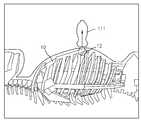
제1 의료 영상의 좌표계와 제2 의료 영상의 좌표계간의 변환 관계를 획득하기 위해, 프로브(111)를 대상체의 기준점(12) 위에 위치시킬 수 있다. 여기서 기준점(12)은 대상체의 개체 중 적어도 하나일 수 있다. 기준점(12)은 제1 의료 영상에서 식별이 용이하고 시간에 따라 변형되지 않는 개체일 수 있다. 예를 들어, 기준점(12)은 대상체의 개체 중 뼈일 수 있다. 사용자는 프로브(111)를 대상체의 기준점(12) 위에 위치시킬 수 있다.The
도 4는 일 실시예에 따른 대상체에 프로브(111)를 위치시키는 참조도면이다. 도 4에 도시된 바와 같이, 사용자는 프로브(111)를 대상체(10)의 개체 중 명치 위에 놓을 수 있다. 여기서 명치가 대상체(10)의 기준점(12)이 될 수 있다. 더 나아가, 사용자는 프로브(111)의 축, 예를 들어, 제1 축을 대상체(10)의 축, 예를 들어, 제4 축(220)과 평행하게 배치시킬 수도 있다.FIG. 4 is a reference drawing of placing a
프로브(111)가 대상체(10)의 기준점(12) 위에 위치할 때, 정합 장치(140)는 프로브(111)를 통해 획득된 제1 의료 영상으로부터 기준점(12)에 대한 좌표 정보를 획득할 수 있다. 상기한 기준점(12)에 대한 좌표 정보는 제1 의료 영상 좌표계를 기준으로 한다. 또한, 정합 장치(140)는 제2 의료 영상으로부터 기준점(12)에 대한 좌표 정보를 획득할 수 있다. 여기서 기준점(12)에 대한 좌표 정보는 제2 의료 영상 좌표계를 기준으로 한다. 그리하여, 제1 의료 영상 좌표계에서의 기준점(12)에 대한 좌표 정보와 제2 의료 영상 좌표계에서의 기준점(12)에 대한 좌표 정보간의 변환 관계를 산출함으로써 제1 의료 영상의 좌표계와 제2 의료 영상의 좌표계간의 변환 관계를 획득할 수 있다.When the
도 5는 도 1에 도시된 정합 장치(140)를 나타내는 블록도이다. 도 5를 참조하면, 정합 장치(140)는 통신부(510), 저장부(520), 사용자 인터페이스(530), 프로세서(540) 및 제어부(550)를 포함할 수 있다. 다만, 도시된 구성요소들이 모두 필수 구성요소들은 아니며, 도시된 구성요소들 이외에 다른 범용적인 구성요소들이 더 포함될 수도 있다.Fig. 5 is a block diagram showing the
통신부(510)는 제1 의료 장치(110) 및 제2 의료 장치(120)로부터 각각 제1 의료 영상과 제2 의료 영상을 수신하고, 검출 장치(130)로부터 프로브(111)의 위치 및 방향 정보 중 적어도 하나를 수신할 수 있다. 통신부(510)는 제1 의료 장치(110) 및 제2 의료 장치(120)로부터 제1 의료 영상 및 제2 의료 영상을 획득하기 위한 인터페이스들(511, 512, 513)을 포함한다. 제1 인터페이스(511) 및 제2 인터페이스(512) 는 제1 의료 장치(110) 및 제2 의료 장치(120)와 직접 또는 간접으로 연결되기 위한 인터페이스를 의미한다.The
제1 인터페이스(511)는 제1 의료 장치(110)가 촬영하는 제1 의료 영상을 실시간 획득할 수 있다. 제2 인터페이스(512)는 제2 의료 장치(120)가 의료시술 이전에 미리 촬영한 제2 의료 영상을 획득하기 위하여, 제2 의료 장치(120)와 직접 연결될 수 있다. 또는, 제2 인터페이스(512)는 다른 외부 저장매체(USB, CD, DVD 등) 또는 네트워크를 통해 제2 의료 영상을 획득할 수 있다. 통신부(510)는 획득한 제2 의료 영상을 저장부(520)에 저장할 수 있다. 제3 인터페이스(513)는 검출 장치(130)로부터 프로브(111)의 좌표 정보를 수신할 수 있다. 프로브(111)의 좌표 정보는 제1 인터페이스(511)로부터 수신된 제1 의료 영상의 단면 영상과 일대일 매칭될 수 있다. 제1 의료 영상과 프로브(111)의 좌표 정보가 서로 다른 인터페이스(511, 513)를 통해 수신된다고 하였으나, 이에 한정되지 않는다. 하나의 인터페이스를 통해 제1 의료 영상과 프로브(111)의 좌표 정보가 수신될 수도 있다.The
사용자 인터페이스(530)는 사용자로부터 정합 장치(140)을 조작하기 위한 입력을 수신하고, 정합 장치(140)가 획득한 제1 의료 영상, 제2 의료 영상 또는 정합된 의료 영상을 출력한다. 사용자 인터페이스(530)는 사용자가 직접 정합 장치(140)를 조작하기 위한 버튼, 키 패드, 스위치, 다이얼 또는 터치 인터페이스를 포함할 수 있다. 사용자 인터페이스(530)는 영상을 디스플레이하기 위한 디스플레이부를 포함할 수 있으며, 터치스크린으로 구현될 수 있다. 또 다른 실시예에서, 사용자 인터페이스(530)는 HID(Human Interface Device) 들을 연결하기 위한 I/O 포트를 구비할 수 있다. 사용자 인터페이스(530)는 영상의 입/출력을 위한 I/O 포트를 구비할 수 있다.The
프로세서(540)는 제1 의료 영상과 그에 대응하는 제2 의료 영상을 정합하여 정합된 영상을 사용자 인터페이스(530)로 출력할 수 있다. 프로세서(540)는 제1 의료 영상으로부터 정합을 위한 개체를 획득하는 제1 획득부(541), 제2 의료 영상으로부터 정합을 위한 개체를 획득하는 제2 획득부(542), 획득된 개체들을 정렬시킴으로써, 제1 의료 영상과 제2 의료 영상간의 변환 관계를 산출하는 산출부(543) 및 제1 의료 영상의 단면 영상에 대응하는 제2 의료 영상의 단면 영상을 제2 의료 영상으로부터 획득하는 제3 획득부(544)를 포함할 수 있다. 제1 및 제2 획득부(541, 542)에서 획득되는 개체는 동일할 수도 있고, 동일하지 않을 수도 있다. 개체들이 동일한지 여부에 따라 변환 관계의 산출 방식이 상이할 수 있다.The
제1 획득부(541)는 제1 의료 영상으로부터 개체를 획득할 수 있다. 상기한 개체는 대상체내의 기준점일 수도 있고, 제1 의료 영상에서 뚜렷하게 나타나는 기준점 이외의 개체일 수도 있다. 예를 들어, 제1 의료 영상이 간을 포함하는 초음파 영상인 경우, 개체는 간 이외에도 간과 인접하게 배치된 하대 정맥 또는 횡경막일 수 있다. 이외에도, 간에 인접한 신장, 담낭, Portal vein, Hepatic vein, IVC 중 적어도 하나 이상이 개체가 될 수 있다.The first acquiring
제2 획득부(542)는 제2 의료 영상으로부터 개체를 획득할 수 있다. 상기한 개체는 대상체내의 기준점일 수도 있고, 제2 의료 영상에서 뚜렷하게 나타나는 기준점 이외의 다른 개체일 수도 있다. 제2 획득부(542)가 획득하는 개체는 제1 획득부(541)가 획득하는 개체와 동일하거나 다를 수 있다. 예를 들어, 관심 장기가 간인 경우, 일반적으로 횡경막, 하대정맥 등은 초음파 영상인 제1 의료 영상과 MR 영상인 제2 의료 영상에 모두 뚜렷하게 나타날 수 있다. 그리하여, 제1 및 제2 획득부(541, 542) 각각은 횡경막 또는 하대 정맥을 개체로 획득할 수 있다. 그러나, 이에 한정되지 않는다. 이하 설명의 편의를 위해 제1 획득부에서 획득된 기준점(12) 이외의 개체를 제1 개체라고 하고, 제2 획득부에서 획득된 기준점(12) 이외의 개체를 제2 개체라고 한다. 제2 획득부(542)는 제1 개체와 다르면서 제1 개체와 인접하게 배치된 제2 개체를 획득할 수 있다. 예를 들어, 제1 개체가 횡경막일 때, 제2 개체는 간일 수 있다. 이때, 간과 횡격막은 동일한 개체는 아니지만, 간의 경계면과 횡격막이 접하므로 횡격막을 간의 경계면으로 간주하면, 횡격막과 간을 정렬시킴으로써 의료 영상들을 정합할 수 있기 때문이다.The second acquiring
산출부(543)는 제1 의료 영상 내 기준점과 제2 의료 영상 내 기준점을 일치시킴으로써 제1 의료 영상과 제2 의료 영상 간의 변환 관계를 산출할 수도 있고, 제1 개체와 제2 개체를 정렬시킴으로써 상기한 변환 관계를 보완할 수 있다. 제1 개체와 제1 개체가 동일한 경우, 산출부(543)는 제1 개체와 제2 개체를 일치시킴으로써 변환 관계를 보완할 수 있다. 그러나, 제1 개체와 제2 개체가 다른 경우, 산출부(543)는 제1 개체와 제2 개체간의 기하학적 배치 구조가 기저장된 기하학적 배치 구조와 일치시킴으로써 변환 관계를 보완할 수 있다. 제1 개체와 제2 개체간의 기하학적 배치 구조가 기저장되어 있을 수 있다.The calculating
상기와 같이, 기준점을 이용하여 제1 의료 영상의 좌표계와 제2 의료 영상의 좌표계간의 변환 관계를 산출하면 임의의 지점을 기준으로 좌표계간의 변환 관계를 산출하는 것보다 산출이 용이할 수 있다.As described above, when calculating the conversion relationship between the coordinate system of the first medical image and the coordinate system of the second medical image using the reference point, calculation can be performed more easily than calculating the conversion relation between coordinate systems based on an arbitrary point.
한편, 제1 및 제2 의료 영상의 기준점에 대한 좌표 정보가 명확한 경우, 제1 의료 영상에서의 기준점에 대한 좌표 정보와 제2 의료 영상에서의 기준점에 대한 좌표 정보의 변환 관계만으로 제1 의료 영상과 제2 의료 영상의 변환 관계를 산출할 수 있다. 그러나, 사용자의 역량 등에 따라 프로브는 기준점 위에 위치할 수도 있고, 약간 어긋날 수도 있다. 따라서, 일 실시예에 따른 정합 장치는 기준점 이외에 대상체의 다른 개체를 이용하여 변환 관계를 보완하는 것이다.On the other hand, when the coordinate information for the reference points of the first and second medical images is clear, only the conversion relationship between the coordinate information for the reference point in the first medical image and the coordinate information for the reference point in the second medical image, And the second medical image can be calculated. However, the probe may be positioned above the reference point, or slightly deviated, depending on the user's capabilities. Accordingly, the matching apparatus according to an embodiment compensates the conversion relation by using another entity of the object other than the reference point.
그리고, 제3 획득부(544)는 제1 의료 영상의 단면 영상에 대응하는 제2 의료 영상의 단면 영상을 제2 의료 영상으로부터 획득할 수 있다. 예를 들어, 제3 획득부(544)는 변환 관계를 이용하여 제1 의료 영상의 단면 영상에 대한 좌표 정보를 제2 의료 영상 좌표계에서의 좌표 정보로 변환시키고, 변환된 좌표 정보를 갖는 제2 의료 영상의 단면 영상을 제2 의료 영상으로부터 획득할 수 있다.The third acquiring
제1 의료 영상의 단면 영상 및 제2 의료 영상의 단면 영상은 표시 장치(150) 또는 사용자 인터페이스(530)로 인가되어, 제1 의료 영상의 단면 영상과 제2 의료 영상의 단면 영상이 함께 표시될 수 있다. 제1 의료 영상과 제2 의료 영상의 단면 영상 각각이 영역을 달리하여 표시될 수도 있고, 융합되어 하나의 영상으로 표시될 수도 있다. A sectional image of the first medical image and a sectional image of the second medical image are applied to the
제어부(550)는 정합 장치(140)의 동작을 전반적으로 제어한다. 예를 들어, 제어부(550)는 사용자 인터페이스(530)를 통해 입력된 사용자 명령이나 저장부(520)에 저장된 프로그램을 이용하여 프로세서(540)가 영상을 생성하도록 제어할 수 있다. 또한, 제어부(550)는 프로세서(540)에서 생성한 영상이 사용자 인터페이스(530) 또는 표시 장치(150)에 표시되도록 제어할 수도 있다.The
정합장치(130)의 보다 상세한 동작에 대해서는, 후술하는 의료영상 정합 방법을 참조하여 설명을 계속한다. 이하에서, 의료영상 정합장치(130)의 어느 구성요소가 각 프로세스를 수행하는지를 구체적으로 특정하지 않더라도, 당업자라면 전술한 설명으로부터 이를 파악할 수 있다.The operation of the
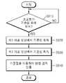
도 6은 일 실시예에 따른 의료 영상을 정합하는 방법을 설명하는 흐름도이다. 도 6을 참조하면, 제어부(550)는 프로브(111)가 대상체의 기준점(12) 위에 위치하는지 판단한다(S610). 사용자는 프로브(111)를 대상체의 기준점(12) 위에 위치시키고, 프로브(111)가 대상체의 기준점(12) 위에 위치하였음을 알리는 사용자 명령을 입력할 수 있다. 그러면, 제어부(550)는 프로브(111)가 기준점(12) 위에 위치하였다고 판단할 수 있다. 여기서 기준점(12)은 대상체의 개체 중 외부 힘에 의해 변형되지 않는 개체일 수 있다. 예를 들어, 기준점(12)은 대상체의 특정 뼈일 수 있다. 프로브(111)가 대상체의 기준점(12) 위에 위치할 때, 제어부(550)는 검출 장치의 좌표계와 제1 의료 영상 좌표계를 매칭시킬 수 있다.6 is a flowchart illustrating a method of matching medical images according to an embodiment. Referring to FIG. 6, the
프로브(111)가 대상체의 기준점(12) 위에 위치하면(S610-Y), 제1 획득부(541)는 제1 의료 영상으로부터 기준점(12)을 획득하고, 제1 의료 영상 좌표계에서 기준점(12)에 대한 좌표 정보를 획득할 수 있다(S620).If the
예를 들어, 제1 의료 장치(110)는 실시간으로 프로브(111)를 통해 제1 의료 영상의 단면 영상을 획득할 수 있고, 제1 의료 영상의 단면 영상을 재구성하여 3차원의 제1 의료 영상을 생성할 수 있다. 그리고, 제1 의료 장치(110)는 3차원의 제1 의료 영상을 정합 장치(140)에 인가하고, 정합 장치(140)의 제1 획득부(541)는 제1 의료 영상으로부터 기준점(12)을 획득할 수 있다. 기준점을 획득함에 있어서, 제1 획득부(541)는 밝기 값을 이용할 수 있다. 그러나, 이에 한정되지 않는다. 밝기 값 이외의 다른 방법으로도 기준점을 획득할 수 있다.For example, the first
제2 획득부(542)도 제2 의료 영상으로부터 기준점(12)을 획득하고, 제2 영상 좌표계에서 상기한 기준점(12)에 대한 좌표 정보를 획득할 수 있다(S630). 한편, 기준점(12)은 제2 의료 영상에 선명하지 않을 수 있다. 이와 같은 경우, 제2 획득부(542)는 기저장된 기준점(12)에 대한 정보를 이용하여 제2 의료 영상 좌표계에서 기준점(12)에 대한 좌표 정보를 예측할 수 있다. 또한, 제1 획득부(541)가 제1 의료 영상으로부터 기준점을 획득한 후 제2 획득부(542)가 제2 의료 영상으로부터 기준점을 획득한다고 설명하였으나, 이는 설명의 편의를 위할 뿐 그 순서는 바뀌어도 무방하고, 동시에 진행하여도 무방하다.The second acquiring
그리고, 산출부(543)는 제1 의료 영상의 기준점(12)과 제2 의료 영상의 기준점(12)을 일치시킴으로써 제1 의료 영상의 좌표계와 제2 의료 영상의 좌표계간의 변환 관계를 산출할 수 있다(S640). 변환 관계는 하기 수학식 1과 같을 수 있다.The
[수학식 1][Equation 1]

여기서,

한편, 프로브(111)를 기준점(12) 위에 위치시킨다 하더라도 사용자의 역량에 따라 프로브(111)의 중심이 기준점(12)의 중심에 정확하게 위치하지 않을 수 있다. 그리고, 경우에 따라서는 상기한 프로브(111)를 통해 실시간으로 획득된 제1 의료 영상에 기준점(12)에 대한 정보가 명확히 포함되지 않을 수 있다. 뿐만 아니라, 제2 의료 영상에 기준점(12)에 대한 정보가 명확히 포함되어 있지 않는 경우, 기준점(12)만으로 제1 의료 영상과 제2 의료 영상간의 변환 관계를 명확히 산출하는 것이 어려울 수 있다. 그리하여, 일 실시예에 따른 정합 장치(140)는 기준점 이외의 대상체내 다른 개체를 이용하여 상기한 변환 관계를 보완할 수 있다.Even if the
도 7은 일 실시예에 따른 변환 관계를 보완하는 방법을 설명하는 흐름도이다. 도 7를 참조하면, 제1 획득부(541)는 제1 의료 영상으로부터 제1 개체를 획득하고, 제1 개체에 대한 좌표 정보를 획득하다(S710). 그리고, 산출부(543)는 제1 개체의 좌표 정보를 변환 관계를 이용하여 제2 영상 좌표계의 좌표 정보로 변환시킨다(S720).7 is a flow chart illustrating a method for compensating for a transformation relationship according to an embodiment. Referring to FIG. 7, the first acquiring
한편, 제2 획득부(542)는 제2 의료 영상으로부터 제2 개체를 획득하고, 제2 개체에 대한 좌표 정보를 획득한다(S730). 제1 및 제2 개체 각각은 제1 및 제2 의료 영상 각각에서 선명하게 표시되는 개체일 수 있다. 제1 및 제2 개체는 동일할 수도 있고, 다를 수 도 있다. 개체 획득 방법은 의료 영상에서 개체를 획득하는 일반적인 기술이 적용되는 바, 구체적인 설명은 생략한다. 또한, 제2 획득부(542)는 제2 의료 영상으로부터 사전에 제2 개체를 획득하여 저장해 놓을 수 있다. 그리하여, 제2 획득부(542)는 기저장된 제2 개체를 로딩할 수도 있다. S710과 S730은 그 순서가 바뀌어도 되고 동시에 진행되어도 무방하다.Meanwhile, the second acquiring
그리고, 산출부(543)는 변환된 제1 개체와 제2 개체를 정렬시킴으로써 제1 의료 영상 좌표계와 제2 의료 영상 좌표계간의 변환 관계를 보완하여 최종적인 변환 관계(Tf)를 획득할 수 있다(S740). 최종 변환 관계는 하기 수학식 2와 같이 산출할 수 있다.The calculating
[수학식 2]&Quot; (2) "

여기서,

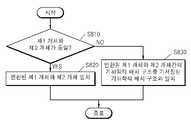
한편, 제1 및 제2 개체가 동일한지 여부에 따라 제1 및 제2 개체의 정렬 방법이 다를 수 있다. 도 8은 일 실시예에 따른 제1 및 제2 개체를 정렬하는 방법을 설명하는 흐름도이다. 먼저, 산출부(543)는 제1 개체와 제2 개체가 동일한지 여부를 판단한다(S810). 산출부(543)는 제1 및 제2 개체의 크기, 반경 등을 고려하여 제1 및 제2 개체가 동일한지 여부를 판단할 수 있다. 또는 제2 개체는 미리 획득되어 저장되어 있을 수 있기 때문에 제2 획득부(542)는 상기한 제2 개체에 대한 정보를 로딩하고, 로딩된 정보로 제2 개체와 동일한 제1 개체를 획득할 수 있다. 이와 같은 경우, 산출부(543)는 제1 및 제2 개체가 동일하다고 판단할 수 있다. 또한, 제1 의료 영상과 제2 의료 영상은 서로 다른 개체가 선명하게 표시될 수 있기 때문에 정합 장치(140)에는 획득하고자 하는 제1 및 제2 개체에 대한 정보가 각각 저장되어 있을 수도 있다. 제1 및 제2 개체가 서로 다른 경우, 정합 장치(140)에는 제1 및 제2 개체에 대한 기하학적 배치 구조에 대한 정보가 기저장되어 있을 수 있다.On the other hand, depending on whether the first and second entities are identical, the sorting method of the first entity and the second entity may be different. 8 is a flow diagram illustrating a method for aligning first and second entities in accordance with one embodiment. First, the
제1 및 제2 개체가 동일하면(S810-Y), 산출부(543)는 변환된 제1 개체와 제2 개체를 일치시킴으로써 변환된 제1 개체와 제2 개체를 정렬시킬 수 있다(S820).If the first and second entities are the same (S810-Y), the calculating
또는 제1 및 제2 개체가 다르면(S810-N), 산출부(543)는 변환된 제1 개체와 제2 개체의 기하학적 배치 구조가 기저장된 기하학적 배치 구조와 일치되도록 제1 개체와 제2 개체를 정렬시킬 수 있다(S830). 상기와 같이, 기준점(12)을 일치시켜 제1 의료 영상과 제2 의료 영상간의 변환 관계를 산출하고, 다시 제1 및 제2 개체를 이용하여 변환 관계를 보완하기 때문에 단순히 제1 및 제2 개체를 정렬시키는 것보다 정합의 오류를 줄일 수 있다.(S810-N), the
뿐만 아니라, 프로브(111)를 기준점(12) 위에 위치시키면서 프로브(111)의 축을 대상체의 축과 평행하게 위치시키면 제1 의료 영상과 제2 의료 영상간의 변환 관계를 산출하는 것이 보다 용이하다, 제2 의료 영상의 좌표축은 대상체의 축과 평행하기 때문에 기준점을 일치시키는 과정이 간소화될 수 있다.In addition, it is easier to calculate the conversion relationship between the first medical image and the second medical image by positioning the axis of the
지금까지 기준점은 제1 개체 또는 제2 개체와 다른 개체로 정의하여 설명하였으며, 기준점을 이용하여 변환 관계를 산출하고, 다른 개체를 이용하여 변환 관계를 보완한다고 설명하였다. 그러나, 이에 한정되지 않는다. 기준점이 제1 개체 또는 제2 개체가 될 수 있다. 그리하여, 프로브가 제1 개체 또는 제2 개체 위에 위치하면, 제1 및 제2 개체를 이용하여 변환 관계를 산출할 수도 있다.So far, the reference point has been defined as the first entity or the second entity and another entity, and the conversion relation is calculated using the reference point, and the conversion relation is supplemented by using other entity. However, it is not limited thereto. The reference point may be a first entity or a second entity. Thus, when the probe is located on the first entity or the second entity, the first and second entities may be used to calculate the conversion relationship.
그리고, 상기한 최종 변환 관계를 이용하여 제1 의료 영상의 단면 영상에 대응하는 제2 의료 영상의 단면 영상을 획득할 수 있다. 도 9는 일 실시예에 따른 제1 의료 영상의 단면 영상에 대응하는 제2 의료 영상의 단면 영상을 획득하는 방법을 설명하는 흐름도이다. 도 9를 참조하면, 제1 의료 장치(110)는 프로브(111)를 통해 제1 의료 영상의 단면 영상을 실시간으로 획득할 수 있다(S910). 제1 의료 장치(110)가 초음파 영상 장치인 경우, 제1 의료 장치(110)는 프로브(111)(probe)를 이용하여 초음파를 대상체에 조사하고, 반사되는 초음파를 검출함으로써 초음파 영상을 생성할 수 있다. 그리고, 획득된 제1 의료 영상은 정합 장치(140)에 인가된다.The sectional image of the second medical image corresponding to the sectional image of the first medical image can be obtained using the final conversion relation. 9 is a flowchart illustrating a method of acquiring a sectional image of a second medical image corresponding to a sectional image of a first medical image according to an exemplary embodiment. Referring to FIG. 9, the first
한편, 검출 장치(130)는 프로브(111)의 움직임을 검출할 수 있다(S920). 프로브(111)가 움직임으로써 대상체에 조사되는 초음파의 위치 및 방향이 달라질 수 있고, 제1 의료 영상의 뷰도 달라질 수 있다. 프로브(111)의 위치 및 방향을 나타내는 정보와 제1 의료 영상의 뷰는 일대일 대응되기 때문에 프로브(111)의 움직임을 검출하면 제1 의료 영상의 뷰도 예측할 수 있다. 제1 의료 영상의 획득과 프로브(111)의 움직임 검출은 동시에 수행될 수 있으나, 설명의 편의를 도모하기 위해 제1 의료 영상의 획득을 먼저 설명하였을 뿐이다.Meanwhile, the
정합 장치(140)는 프로브(111)의 움직임에 대응하는 제2 의료 영상의 단면 영상을 제2 의료 영상으로부터 획득할 수 있다(S930). 제2 의료 영상은 기촬영된 영상일 수 있다. 그리고, 제2 의료 영상은 제1 의료 영상에 비해 장기와 병변의 형상이 선명할 수 있다. 제2 의료 영상은 제2 의료 장치(120)로부터 수신할 수도 있고, 저장된 영상일 수도 있다. 예를 들어, 제2 의료 영상은 CT 영상 또는 MR 영상일 수 있다. 구체적으로, 프로브(111)의 이동 및 회전 중 적어도 하나에 따라 프로브(111)의 위치 및 방향 중 적어도 하나가 변경되면 검출 장치(130)는 프로브(111)를 재검출하고, 재검출된 프로브(111)의 위치 및 방향 정보를 정합 장치(140)에 인가할 수 있다. 프로브(111)의 위치 및 방향 정보는 제1 의료 영상의 단면 영상에 대한 좌표 정보와 일대일 대응되기 때문에, 산출부(543)는 최종 변환 관계(Tf)를 이용하여 하기 수학식 2와 같이, 재검출된 제1 의료 영상의 단면 영상에 대한 좌표 정보(

[수학식 2]
&Quot; (2) "
그리고, 제3 획득부(544)는 제2 의료 영상으로부터 변환된 좌표 정보를 갖는 단면 영상을 획득할 수 있다. 상기한 제1 의료 영상의 단면 영상과 그에 대응하는 제2 의료 영상의 단면 영상은 대상체에 대한 동일한 뷰일 수 있다. 제1 의료 영상의 단면 영상과 그에 대응하는 제2 의료 영상의 단면 영상은 사용자 인터페이스(530) 또는 표시 장치(150)를 통해 외부로 함께 표시될 수 있다. 제1 의료 영상의 단면 영상과 그에 대응하는 제2 의료 영상의 단면 영상은 하나의 화면에 영역을 달리하여 표시될 수도 있고, 하나의 영역에 중첩되어 표시될 수도 있다.The third acquiring
상기와 같이 기준점을 이용하여 제1 의료 영상의 좌표계와 제2 의료 영상의 좌표계간의 변환 관계를 산출하기 때문에 임의의 초기 위치에서 모달리티가 다른 복수 개의 영상을 정합하는 것보다 정합 처리가 간소화될 수 있고, 영상 정합의 오류를 줄일 수 있다. 또한, 다른 개체를 이용하여 변환 관계를 보완할 수 있기 때문에 변환 관계를 보다 정확하게 획득할 수 있다.Since the conversion relation between the coordinate system of the first medical image and the coordinate system of the second medical image is calculated using the reference point as described above, the matching process can be simplified compared to matching a plurality of images having different modalities at an arbitrary initial position , It is possible to reduce errors in image registration. In addition, since the conversion relation can be supplemented by using another entity, the conversion relation can be obtained more accurately.
한편, 상술한 의료 영상들의 정합 방법은 컴퓨터에서 실행될 수 있는 프로그램으로 작성 가능하고, 컴퓨터로 읽을 수 있는 기록매체를 이용하여 상기 프로그램을 동작시키는 범용 디지털 컴퓨터에서 구현될 수 있다. 또한, 상술한 본 발명의 실시예에서 사용된 데이터의 구조는 컴퓨터로 읽을 수 있는 기록매체에 여러 수단을 통하여 기록될 수 있다. 상기 컴퓨터로 읽을 수 있는 기록매체는 마그네틱 저장매체(예를 들면, 롬, 플로피 디스크, 하드 디스크 등), 광학적 판독 매체(예를 들면, 시디롬, 디브이디 등)와 같은 저장매체를 포함한다.Meanwhile, the above-described method of matching medical images can be realized as a program that can be executed by a computer, and can be implemented in a general-purpose digital computer that operates the program using a computer-readable recording medium. In addition, the structure of data used in the above-described embodiments of the present invention can be recorded on a computer-readable recording medium through various means. The computer-readable recording medium includes a storage medium such as a magnetic storage medium (e.g., ROM, floppy disk, hard disk, etc.), optical reading medium (e.g., CD ROM,
이제까지 그 바람직한 실시예들을 중심으로 살펴보았다. 본 발명이 속하는 기술 분야에서 통상의 지식을 가진 자는 본 발명이 본 발명의 본질적인 특성에서 벗어나지 않는 범위에서 변형된 형태로 구현될 수 있음을 이해할 수 있을 것이다. 그러므로 개시된 실시예들은 한정적인 관점이 아니라 설명적인 관점에서 고려되어야 한다. 본 발명의 범위는 전술한 설명이 아니라 특허청구범위에 나타나 있으며, 그와 동등한 범위 내에 있는 모든 차이점은 본 발명에 포함된 것으로 해석되어야 할 것이다.So far, the preferred embodiments have been mainly described. It will be understood by those skilled in the art that various changes in form and details may be made therein without departing from the spirit and scope of the invention as defined by the appended claims. Therefore, the disclosed embodiments should be considered in an illustrative rather than a restrictive sense. The scope of the present invention is defined by the appended claims rather than by the foregoing description, and all differences within the scope of equivalents thereof should be construed as being included in the present invention.
100: 의료 영상 시스템 110: 제1 의료 장치
111: 프로브 120: 제2 의료 장치
130: 검출 장치 140: 정합 장치
150: 표시 장치 310: 통신부
320: 저장부 330: 사용자 인터페이스
540: 프로세서 541: 제1 획득부
542: 제2 획득부 543: 산출부
544: 제3 산출부 550: 제어부100: medical imaging system 110: first medical device
111: probe 120: second medical device
130: Detecting device 140: Matching device
150: Display device 310:
320: storage unit 330: user interface
540: Processor 541: First acquiring unit
542: second obtaining unit 543: calculating unit
544: third calculating section 550:
Claims (20)
Translated fromKorean상기 변환 관계를 이용하여 상기 제2 의료 영상으로부터 상기 제1 의료 영상의 단면 영상에 대응하는 상기 제2 의료 영상의 단면 영상을 획득하는 단계;를 포함하는 의료 영상 정합 방법.Calculating a conversion relationship by which the first medical image obtained through the probe and the second medical image having a different modality from the first medical image can be matched using the reference point if the probe is located above the reference point of the object; And
And obtaining a sectional image of the second medical image corresponding to the sectional image of the first medical image from the second medical image using the conversion relation.
상기 기준점은
상기 대상체 중 시간에 따라 변형되지 않는 개체인 의료 영상 정합 방법.The method according to claim 1,
The reference point
Wherein the object is an object that does not change with time among the objects.
상기 개체는,
뼈인 의료 영상 정합 방법.3. The method of claim 2,
The apparatus of claim 1,
Medical image matching method which is bone.
상기 변환 관계를 산출하는 단계는,
상기 기준점을 이용하여 상기 제1 의료 영상의 좌표계와 상기 제2 의료 영상의 좌표계간의 변환 관계를 산출하는 단계;를 포함하는 의료 영상 정합 방법.The method according to claim 1,
Wherein the step of calculating the conversion relation comprises:
And calculating a conversion relationship between a coordinate system of the first medical image and a coordinate system of the second medical image using the reference point.
상기 제1 의료 영상에 포함된 제1 개체와 상기 제2 의료 영상에 포함된 제2 개체를 정렬시킴으로써 상기 변환 관계를 보완하는 단계;를 더 포함하는 의료 영상 정합 방법.5. The method of claim 4,
Further comprising: arranging a first entity included in the first medical image and a second entity included in the second medical image to complement the conversion relationship.
상기 정렬은,
상기 제1 개체와 상기 제2 개체가 동일한 경우, 상기 제1 개체와 상기 제2 개체를 일치시키는 의료 영상 정합 방법.6. The method of claim 5,
The alignment may include,
Wherein if the first entity and the second entity are identical, the first entity and the second entity are matched.
상기 정렬은
상기 제1 개체와 상기 제2 개체가 다른 경우, 상기 제1 개체와 상기 제2 개체간의 기하학적 배치 구조를 기저장된 기하학적 배치 구조와 일치시키는 의료 영상 정합 방법.6. The method of claim 5,
The alignment
Wherein the geometric arrangement structure between the first entity and the second entity is matched with a pre-stored geometric arrangement structure when the first entity and the second entity are different.
상기 프로브가 대상체의 기준점 위에 위치할 때, 상기 프로브의 축은 상기 대상체의 축과 평행하게 배치되는 의료 영상 정합 방법.The method according to claim 1,
Wherein the axis of the probe is disposed in parallel with the axis of the object when the probe is positioned above a reference point of the object.
상기 대상체의 축은 상기 제2 의료 영상의 좌표축과 평행한 의료 영상 정합 방법.9. The method of claim 8,
Wherein the axis of the object is parallel to a coordinate axis of the second medical image.
상기 제2 의료 영상의 단면 영상을 획득하는 단계는,
상기 제1 의료 영상의 단면 영상에 대한 좌표 정보를 획득하는 단계;
상기 변환 관계를 이용하여 상기 좌표 정보를 상기 제2 의료 영상에서의 좌표 정보로 변환하는 단계; 및
상기 변환된 좌표 정보를 갖는 제2 의료 영상의 단면 영상을 상기 제2 의료 영상으로부터 획득하는 단계;를 포함하는 의료 영상 정합 방법.The method according to claim 1,
Wherein the acquiring of the cross-sectional image of the second medical image comprises:
Obtaining coordinate information on a sectional image of the first medical image;
Converting the coordinate information into coordinate information in the second medical image using the conversion relation; And
And obtaining a sectional image of a second medical image having the converted coordinate information from the second medical image.
상기 제1 의료 영상의 단면 영상에 대한 좌표 정보는 상기 프로브의 위치 및 방향 정보와 대응되는 의료 영상 정합 방법.The method according to claim 1,
Wherein the coordinate information of the sectional image of the first medical image corresponds to the position and orientation information of the probe.
상기 제1 의료 영상은 실시간으로 촬영된 영상이고,
상기 제2 의료 영상은 기촬영된 영상인 의료 영상 정합 방법.The method according to claim 1,
Wherein the first medical image is an image photographed in real time,
And the second medical image is a previously photographed image.
상기 제1 의료 영상은 초음파 영상 및 OCT 영상 중 어느 하나이고,
상기 제2 의료 영상은 MR, CT, PET, SPECT, 및 X-ray 영상 중 어느 하나인 의료 영상 정합 방법.The method according to claim 1,
Wherein the first medical image is one of an ultrasound image and an OCT image,
Wherein the second medical image is any one of MR, CT, PET, SPECT, and X-ray images.
상기 제2 의료 영상의 단면 영상을 상기 제1 의료 영상의 단면 영상과 함께 표시하는 단계;를 더 포함하는 의료 영상 정합 방법.The method according to claim 1,
And displaying a sectional image of the second medical image together with a sectional image of the first medical image.
상기 프로브가 대상체의 기준점 위에 위치하면, 제1 의료 영상 및 상기 제1 의료 영상과 모달리티가 다른 제2 의료 영상을 정합시킬 수 있는 변환 관계를 상기 기준점을 이용하여 산출하는 프로세서;를 포함하는 의료 영상 장치.An interface for receiving at least one of position and orientation information of a probe acquiring a first medical image; And
And a processor for calculating a conversion relationship by which the first medical image and the second medical image having a different modality from the first medical image are matched with each other using the reference point if the probe is located above the reference point of the object, Device.
상기 기준점은
상기 대상체 중 시간에 따라 변형되지 않는 개체인 의료 영상 장치.17. The method of claim 16,
The reference point
Wherein the object is an object that does not change with time among the objects.
상기 변환 관계는,
상기 제1 의료 영상에 포함된 제1 개체와 상기 제2 의료 영상에 포함된 제2 개체를 정렬시킴으로써 보완되는 의료 영상 장치.The method of claim 16, wherein
The conversion relationship may include:
Wherein the first medical image is supplemented by aligning a first entity included in the first medical image and a second entity included in the second medical image.
상기 프로브가 대상체의 기준점 위에 위치할 때, 상기 프로브의 축은 상기 대상체의 축과 평행하게 배치되는 의료 영상 장치.17. The method of claim 16,
And the axis of the probe is disposed in parallel with the axis of the object when the probe is located above the reference point of the object.
프로브의 위치 및 방향 정보 중 적어도 하나를 검출하는 검출기;를 더 포함하는 의료 영상 장치.17. The method of claim 16,
And a detector for detecting at least one of position and orientation information of the probe.
Priority Applications (2)
| Application Number | Priority Date | Filing Date | Title |
|---|---|---|---|
| KR1020140074506AKR102273020B1 (en) | 2014-06-18 | 2014-06-18 | Method and appartus for registering medical images |
| US14/736,914US9842379B2 (en) | 2014-06-18 | 2015-06-11 | Method and apparatus for registering medical images |
Applications Claiming Priority (1)
| Application Number | Priority Date | Filing Date | Title |
|---|---|---|---|
| KR1020140074506AKR102273020B1 (en) | 2014-06-18 | 2014-06-18 | Method and appartus for registering medical images |
Publications (2)
| Publication Number | Publication Date |
|---|---|
| KR20150145106Atrue KR20150145106A (en) | 2015-12-29 |
| KR102273020B1 KR102273020B1 (en) | 2021-07-05 |
Family
ID=54870098
Family Applications (1)
| Application Number | Title | Priority Date | Filing Date |
|---|---|---|---|
| KR1020140074506AActiveKR102273020B1 (en) | 2014-06-18 | 2014-06-18 | Method and appartus for registering medical images |
Country Status (2)
| Country | Link |
|---|---|
| US (1) | US9842379B2 (en) |
| KR (1) | KR102273020B1 (en) |
Cited By (3)
| Publication number | Priority date | Publication date | Assignee | Title |
|---|---|---|---|---|
| KR20170084435A (en)* | 2016-01-12 | 2017-07-20 | 삼성메디슨 주식회사 | Ultrasound imaging apparatus and control method for the same |
| KR102084598B1 (en)* | 2019-08-16 | 2020-03-05 | 주식회사 딥노이드 | Ai based surgery assistant system for operating lesion of bone |
| KR20200059910A (en)* | 2018-11-22 | 2020-05-29 | 삼성메디슨 주식회사 | Ultrasound imaging apparatus and control method for the same |
Families Citing this family (8)
| Publication number | Priority date | Publication date | Assignee | Title |
|---|---|---|---|---|
| JP5950619B2 (en)* | 2011-04-06 | 2016-07-13 | キヤノン株式会社 | Information processing device |
| US10966688B2 (en)* | 2014-08-26 | 2021-04-06 | Rational Surgical Solutions, Llc | Image registration for CT or MR imagery and ultrasound imagery using mobile device |
| US9934570B2 (en) | 2015-10-09 | 2018-04-03 | Insightec, Ltd. | Systems and methods for registering images obtained using various imaging modalities and verifying image registration |
| WO2018006168A1 (en)* | 2016-07-05 | 2018-01-11 | 7D Surgical Inc. | Systems and methods for performing intraoperative image registration |
| WO2018232514A1 (en)* | 2017-06-23 | 2018-12-27 | 7D Surgical Inc. | SYSTEMS AND METHODS FOR PEROPERATIVE SURFACE RECORDING AND NAVIGATION |
| CN116529756B (en)* | 2020-12-03 | 2025-03-28 | 西安大医集团股份有限公司 | Monitoring method, device and computer storage medium |
| CN115482180A (en)* | 2021-05-31 | 2022-12-16 | 通用电气精准医疗有限责任公司 | Target area determination method and medical imaging system |
| CN116703994B (en)* | 2023-07-31 | 2023-10-24 | 柏意慧心(杭州)网络科技有限公司 | Method, computing device and computer readable storage medium for medical image registration |
Citations (8)
| Publication number | Priority date | Publication date | Assignee | Title |
|---|---|---|---|---|
| JP2003144412A (en)* | 2001-11-14 | 2003-05-20 | Ge Medical Systems Global Technology Co Llc | Image diagnosis support system and image processing method |
| JP2010515472A (en)* | 2006-11-27 | 2010-05-13 | コーニンクレッカ フィリップス エレクトロニクス エヌ ヴィ | System and method for fusing real-time ultrasound images to pre-collected medical images |
| JP2010131269A (en)* | 2008-12-05 | 2010-06-17 | Canon Inc | Information processor and information processing method |
| KR20110013036A (en)* | 2009-07-31 | 2011-02-09 | 주식회사 메디슨 | Ultrasound system and method for performing calibration of sensors |
| US8355775B2 (en)* | 2004-06-03 | 2013-01-15 | Hitachi Medical Corporation | Image diagnosing support method and image diagnosing support apparatus |
| US20150070469A1 (en)* | 2013-09-06 | 2015-03-12 | Canon Kabushiki Kaisha | Image processing apparatus and image processing method |
| US9131922B2 (en)* | 2013-01-29 | 2015-09-15 | Eigen, Inc. | Calibration for 3D reconstruction of medical images from a sequence of 2D images |
| US9351709B2 (en)* | 2013-08-23 | 2016-05-31 | General Electric Company | Image processing method and apparatus and program |
Family Cites Families (7)
| Publication number | Priority date | Publication date | Assignee | Title |
|---|---|---|---|---|
| JP2006296464A (en) | 2005-04-15 | 2006-11-02 | Toshiba Corp | Ultrasonic diagnostic equipment |
| KR20080053057A (en) | 2006-12-08 | 2008-06-12 | 주식회사 메디슨 | Ultrasound Imaging System and Method for Forming and Displaying Mixed Image of Ultrasound Image and External Medical Image |
| US8320711B2 (en) | 2007-12-05 | 2012-11-27 | Biosense Webster, Inc. | Anatomical modeling from a 3-D image and a surface mapping |
| US8111892B2 (en) | 2008-06-04 | 2012-02-07 | Medison Co., Ltd. | Registration of CT image onto ultrasound images |
| KR101121353B1 (en) | 2009-08-03 | 2012-03-09 | 한국과학기술원 | System and method for providing 2-dimensional ct image corresponding to 2-dimensional ultrasound image |
| WO2012078006A2 (en)* | 2010-12-09 | 2012-06-14 | 삼성전자 주식회사 | Image processor, lighting processor and method therefor |
| US8607193B2 (en)* | 2012-01-16 | 2013-12-10 | International Business Machines Corporation | Tracking stale comments in source code listings |
- 2014
- 2014-06-18KRKR1020140074506Apatent/KR102273020B1/enactiveActive
- 2015
- 2015-06-11USUS14/736,914patent/US9842379B2/enactiveActive
Patent Citations (9)
| Publication number | Priority date | Publication date | Assignee | Title |
|---|---|---|---|---|
| JP2003144412A (en)* | 2001-11-14 | 2003-05-20 | Ge Medical Systems Global Technology Co Llc | Image diagnosis support system and image processing method |
| US8355775B2 (en)* | 2004-06-03 | 2013-01-15 | Hitachi Medical Corporation | Image diagnosing support method and image diagnosing support apparatus |
| JP2010515472A (en)* | 2006-11-27 | 2010-05-13 | コーニンクレッカ フィリップス エレクトロニクス エヌ ヴィ | System and method for fusing real-time ultrasound images to pre-collected medical images |
| JP2010131269A (en)* | 2008-12-05 | 2010-06-17 | Canon Inc | Information processor and information processing method |
| US20100239150A1 (en)* | 2008-12-05 | 2010-09-23 | Canon Kabushiki Kaisha | Information processing apparatus for registrating medical images, information processing method and program |
| KR20110013036A (en)* | 2009-07-31 | 2011-02-09 | 주식회사 메디슨 | Ultrasound system and method for performing calibration of sensors |
| US9131922B2 (en)* | 2013-01-29 | 2015-09-15 | Eigen, Inc. | Calibration for 3D reconstruction of medical images from a sequence of 2D images |
| US9351709B2 (en)* | 2013-08-23 | 2016-05-31 | General Electric Company | Image processing method and apparatus and program |
| US20150070469A1 (en)* | 2013-09-06 | 2015-03-12 | Canon Kabushiki Kaisha | Image processing apparatus and image processing method |
Cited By (3)
| Publication number | Priority date | Publication date | Assignee | Title |
|---|---|---|---|---|
| KR20170084435A (en)* | 2016-01-12 | 2017-07-20 | 삼성메디슨 주식회사 | Ultrasound imaging apparatus and control method for the same |
| KR20200059910A (en)* | 2018-11-22 | 2020-05-29 | 삼성메디슨 주식회사 | Ultrasound imaging apparatus and control method for the same |
| KR102084598B1 (en)* | 2019-08-16 | 2020-03-05 | 주식회사 딥노이드 | Ai based surgery assistant system for operating lesion of bone |
Also Published As
| Publication number | Publication date |
|---|---|
| KR102273020B1 (en) | 2021-07-05 |
| US20150371361A1 (en) | 2015-12-24 |
| US9842379B2 (en) | 2017-12-12 |
Similar Documents
| Publication | Publication Date | Title |
|---|---|---|
| KR102273020B1 (en) | Method and appartus for registering medical images | |
| US20190272632A1 (en) | Method and a system for registering a 3d pre acquired image coordinates system with a medical positioning system coordinate system and with a 2d image coordinate system | |
| US10542955B2 (en) | Method and apparatus for medical image registration | |
| KR102233966B1 (en) | Method and Appartus for registering medical images | |
| CN103829949B (en) | Patient Motion Compensation in In Vivo Probe Tracking Systems | |
| JP6833533B2 (en) | Ultrasonic diagnostic equipment and ultrasonic diagnostic support program | |
| JP6182045B2 (en) | Image processing apparatus and method | |
| KR102369652B1 (en) | Image processing apparatus, medical image apparatus and processing method for the medical image | |
| JP2018520746A (en) | 3D ultrasound imaging and related methods, apparatus, and systems | |
| KR20140096919A (en) | Method and Apparatus for medical image registration | |
| KR20150118484A (en) | Method and Apparatus for medical image registration | |
| JP2014530348A (en) | Radiation imaging system and method for updating an original radiation image | |
| US9990725B2 (en) | Medical image processing apparatus and medical image registration method using virtual reference point for registering images | |
| KR20140127635A (en) | Method and apparatus for image registration | |
| US12211221B2 (en) | Systems and methods for enhancement of 3D imagery and navigation via integration of patient motion data | |
| US10076311B2 (en) | Method and apparatus for registering medical images | |
| US9521980B2 (en) | Method for registering medical images, apparatus performing the method, and computer readable media including the method | |
| JP2018134197A (en) | Medical procedure navigation system and method | |
| KR20160041803A (en) | Image processing apparatus and control method for the same, and medical image apparatus | |
| CN116211464A (en) | Medical image processing device, medical image processing method and storage medium | |
| JP6461257B2 (en) | Image processing apparatus and method | |
| KR102336446B1 (en) | Method and appartus for registering medical images | |
| US20250157058A1 (en) | System And Methods For Enhancement Of 3D Imagery And Navigation Via Integration Of Patient Motion Data |
Legal Events
| Date | Code | Title | Description |
|---|---|---|---|
| PA0109 | Patent application | Patent event code:PA01091R01D Comment text:Patent Application Patent event date:20140618 | |
| PG1501 | Laying open of application | ||
| A201 | Request for examination | ||
| PA0201 | Request for examination | Patent event code:PA02012R01D Patent event date:20190617 Comment text:Request for Examination of Application Patent event code:PA02011R01I Patent event date:20140618 Comment text:Patent Application | |
| E902 | Notification of reason for refusal | ||
| PE0902 | Notice of grounds for rejection | Comment text:Notification of reason for refusal Patent event date:20201103 Patent event code:PE09021S01D | |
| E701 | Decision to grant or registration of patent right | ||
| PE0701 | Decision of registration | Patent event code:PE07011S01D Comment text:Decision to Grant Registration Patent event date:20210521 | |
| GRNT | Written decision to grant | ||
| PR0701 | Registration of establishment | Comment text:Registration of Establishment Patent event date:20210629 Patent event code:PR07011E01D | |
| PR1002 | Payment of registration fee | Payment date:20210630 End annual number:3 Start annual number:1 | |
| PG1601 | Publication of registration |