KR20150143802A - Radiation collector, cooling system and lithographic apparatus - Google Patents
Radiation collector, cooling system and lithographic apparatusDownload PDFInfo
- Publication number
- KR20150143802A KR20150143802AKR1020157032771AKR20157032771AKR20150143802AKR 20150143802 AKR20150143802 AKR 20150143802AKR 1020157032771 AKR1020157032771 AKR 1020157032771AKR 20157032771 AKR20157032771 AKR 20157032771AKR 20150143802 AKR20150143802 AKR 20150143802A
- Authority
- KR
- South Korea
- Prior art keywords
- radiation
- radiation collector
- collector
- focus
- cooling system
- Prior art date
- Legal status (The legal status is an assumption and is not a legal conclusion. Google has not performed a legal analysis and makes no representation as to the accuracy of the status listed.)
- Ceased
Links
- 230000005855radiationEffects0.000titleclaimsabstractdescription608
- 238000001816coolingMethods0.000titleclaimsdescription42
- 239000000356contaminantSubstances0.000claimsdescription68
- 239000000758substrateSubstances0.000claimsdescription63
- 230000003287optical effectEffects0.000claimsdescription57
- 239000002826coolantSubstances0.000claimsdescription45
- 238000000034methodMethods0.000claimsdescription36
- OKKJLVBELUTLKV-UHFFFAOYSA-NMethanolChemical compoundOCOKKJLVBELUTLKV-UHFFFAOYSA-N0.000claimsdescription18
- 238000009499grossingMethods0.000claimsdescription18
- 239000007788liquidSubstances0.000claimsdescription18
- 239000012071phaseSubstances0.000claimsdescription16
- RYGMFSIKBFXOCR-UHFFFAOYSA-NCopperChemical compound[Cu]RYGMFSIKBFXOCR-UHFFFAOYSA-N0.000claimsdescription13
- 229910052802copperInorganic materials0.000claimsdescription13
- 239000010949copperSubstances0.000claimsdescription13
- 239000000463materialSubstances0.000claimsdescription12
- 230000008859changeEffects0.000claimsdescription11
- 239000011888foilSubstances0.000claimsdescription8
- 239000007791liquid phaseSubstances0.000claimsdescription7
- 229910052751metalInorganic materials0.000claimsdescription6
- 239000002184metalSubstances0.000claimsdescription6
- 230000009471actionEffects0.000claimsdescription3
- XNMUCIILODALDI-UHFFFAOYSA-Nnickel phosphoric acidChemical compound[Ni].P(O)(O)(O)=OXNMUCIILODALDI-UHFFFAOYSA-N0.000claimsdescription3
- 239000007789gasSubstances0.000description40
- 239000010410layerSubstances0.000description26
- 239000000446fuelSubstances0.000description25
- 238000000059patterningMethods0.000description23
- 238000009826distributionMethods0.000description14
- CURLTUGMZLYLDI-UHFFFAOYSA-NCarbon dioxideChemical compoundO=C=OCURLTUGMZLYLDI-UHFFFAOYSA-N0.000description12
- 238000005286illuminationMethods0.000description9
- 229910052718tinInorganic materials0.000description8
- ATJFFYVFTNAWJD-UHFFFAOYSA-NTinChemical compound[Sn]ATJFFYVFTNAWJD-UHFFFAOYSA-N0.000description7
- 238000002310reflectometryMethods0.000description7
- 230000007704transitionEffects0.000description7
- 239000001569carbon dioxideSubstances0.000description6
- 229910002092carbon dioxideInorganic materials0.000description6
- 238000013461designMethods0.000description6
- 238000004519manufacturing processMethods0.000description6
- 230000004075alterationEffects0.000description5
- 238000001459lithographyMethods0.000description5
- 229910000159nickel phosphateInorganic materials0.000description5
- JOCJYBPHESYFOK-UHFFFAOYSA-Knickel(3+);phosphateChemical compound[Ni+3].[O-]P([O-])([O-])=OJOCJYBPHESYFOK-UHFFFAOYSA-K0.000description5
- 210000001747pupilAnatomy0.000description5
- 230000002829reductive effectEffects0.000description5
- UFHFLCQGNIYNRP-UHFFFAOYSA-NHydrogenChemical compound[H][H]UFHFLCQGNIYNRP-UHFFFAOYSA-N0.000description4
- 230000008901benefitEffects0.000description4
- 238000011109contaminationMethods0.000description4
- 230000033001locomotionEffects0.000description4
- WHXSMMKQMYFTQS-UHFFFAOYSA-NLithiumChemical compound[Li]WHXSMMKQMYFTQS-UHFFFAOYSA-N0.000description3
- 238000010521absorption reactionMethods0.000description3
- 238000010438heat treatmentMethods0.000description3
- 229910052744lithiumInorganic materials0.000description3
- 238000005498polishingMethods0.000description3
- XUIMIQQOPSSXEZ-UHFFFAOYSA-NSiliconChemical compound[Si]XUIMIQQOPSSXEZ-UHFFFAOYSA-N0.000description2
- 230000008878couplingEffects0.000description2
- 238000010168coupling processMethods0.000description2
- 238000005859coupling reactionMethods0.000description2
- 230000003247decreasing effectEffects0.000description2
- 230000009977dual effectEffects0.000description2
- 230000005670electromagnetic radiationEffects0.000description2
- 238000000227grindingMethods0.000description2
- 150000002500ionsChemical class0.000description2
- 239000011159matrix materialSubstances0.000description2
- 230000000737periodic effectEffects0.000description2
- 230000010363phase shiftEffects0.000description2
- 238000012545processingMethods0.000description2
- 230000009467reductionEffects0.000description2
- 229910052710siliconInorganic materials0.000description2
- 239000010703siliconSubstances0.000description2
- 239000012808vapor phaseSubstances0.000description2
- XLYOFNOQVPJJNP-UHFFFAOYSA-NwaterSubstancesOXLYOFNOQVPJJNP-UHFFFAOYSA-N0.000description2
- 229910052724xenonInorganic materials0.000description2
- FHNFHKCVQCLJFQ-UHFFFAOYSA-Nxenon atomChemical compound[Xe]FHNFHKCVQCLJFQ-UHFFFAOYSA-N0.000description2
- 2380000101463D printingMethods0.000description1
- ZOKXTWBITQBERF-UHFFFAOYSA-NMolybdenumChemical compound[Mo]ZOKXTWBITQBERF-UHFFFAOYSA-N0.000description1
- 238000013459approachMethods0.000description1
- 230000002238attenuated effectEffects0.000description1
- 239000003990capacitorSubstances0.000description1
- 239000011248coating agentSubstances0.000description1
- 238000000576coating methodMethods0.000description1
- 238000010276constructionMethods0.000description1
- 238000005260corrosionMethods0.000description1
- 230000007797corrosionEffects0.000description1
- 230000001419dependent effectEffects0.000description1
- 230000008021depositionEffects0.000description1
- 230000005284excitationEffects0.000description1
- 238000000605extractionMethods0.000description1
- 239000012530fluidSubstances0.000description1
- 239000007792gaseous phaseSubstances0.000description1
- 229910052736halogenInorganic materials0.000description1
- 150000002367halogensChemical class0.000description1
- 238000003384imaging methodMethods0.000description1
- 239000011261inert gasSubstances0.000description1
- 238000007689inspectionMethods0.000description1
- 230000001678irradiating effectEffects0.000description1
- 239000002346layers by functionSubstances0.000description1
- 230000000670limiting effectEffects0.000description1
- 238000005259measurementMethods0.000description1
- 150000002739metalsChemical class0.000description1
- 229910052750molybdenumInorganic materials0.000description1
- 239000011733molybdenumSubstances0.000description1
- 238000013021overheatingMethods0.000description1
- 230000036961partial effectEffects0.000description1
- 239000002245particleSubstances0.000description1
- 230000036278prepulseEffects0.000description1
- 238000007639printingMethods0.000description1
- 230000008569processEffects0.000description1
- 230000000750progressive effectEffects0.000description1
- 230000001902propagating effectEffects0.000description1
- 230000006798recombinationEffects0.000description1
- 238000005215recombinationMethods0.000description1
- 239000003507refrigerantSubstances0.000description1
- 238000007789sealingMethods0.000description1
- 239000004065semiconductorSubstances0.000description1
- 238000007493shaping processMethods0.000description1
- 238000004904shorteningMethods0.000description1
- 238000001228spectrumMethods0.000description1
- 230000003068static effectEffects0.000description1
- 238000003860storageMethods0.000description1
- 230000003746surface roughnessEffects0.000description1
- 230000005469synchrotron radiationEffects0.000description1
- 238000012546transferMethods0.000description1
- 238000009827uniform distributionMethods0.000description1
- 238000011144upstream manufacturingMethods0.000description1
Images


Classifications
- G—PHYSICS
- G02—OPTICS
- G02B—OPTICAL ELEMENTS, SYSTEMS OR APPARATUS
- G02B19/00—Condensers, e.g. light collectors or similar non-imaging optics
- G02B19/0004—Condensers, e.g. light collectors or similar non-imaging optics characterised by the optical means employed
- G02B19/0019—Condensers, e.g. light collectors or similar non-imaging optics characterised by the optical means employed having reflective surfaces only (e.g. louvre systems, systems with multiple planar reflectors)
- G02B19/0023—Condensers, e.g. light collectors or similar non-imaging optics characterised by the optical means employed having reflective surfaces only (e.g. louvre systems, systems with multiple planar reflectors) at least one surface having optical power
- G—PHYSICS
- G03—PHOTOGRAPHY; CINEMATOGRAPHY; ANALOGOUS TECHNIQUES USING WAVES OTHER THAN OPTICAL WAVES; ELECTROGRAPHY; HOLOGRAPHY
- G03F—PHOTOMECHANICAL PRODUCTION OF TEXTURED OR PATTERNED SURFACES, e.g. FOR PRINTING, FOR PROCESSING OF SEMICONDUCTOR DEVICES; MATERIALS THEREFOR; ORIGINALS THEREFOR; APPARATUS SPECIALLY ADAPTED THEREFOR
- G03F7/00—Photomechanical, e.g. photolithographic, production of textured or patterned surfaces, e.g. printing surfaces; Materials therefor, e.g. comprising photoresists; Apparatus specially adapted therefor
- G03F7/70—Microphotolithographic exposure; Apparatus therefor
- G03F7/70058—Mask illumination systems
- G03F7/7015—Details of optical elements
- G03F7/70175—Lamphouse reflector arrangements or collector mirrors, i.e. collecting light from solid angle upstream of the light source
- G—PHYSICS
- G02—OPTICS
- G02B—OPTICAL ELEMENTS, SYSTEMS OR APPARATUS
- G02B19/00—Condensers, e.g. light collectors or similar non-imaging optics
- G02B19/0033—Condensers, e.g. light collectors or similar non-imaging optics characterised by the use
- G02B19/009—Condensers, e.g. light collectors or similar non-imaging optics characterised by the use for use with infrared radiation
- G—PHYSICS
- G02—OPTICS
- G02B—OPTICAL ELEMENTS, SYSTEMS OR APPARATUS
- G02B27/00—Optical systems or apparatus not provided for by any of the groups G02B1/00 - G02B26/00, G02B30/00
- G02B27/0006—Optical systems or apparatus not provided for by any of the groups G02B1/00 - G02B26/00, G02B30/00 with means to keep optical surfaces clean, e.g. by preventing or removing dirt, stains, contamination, condensation
- G—PHYSICS
- G02—OPTICS
- G02B—OPTICAL ELEMENTS, SYSTEMS OR APPARATUS
- G02B5/00—Optical elements other than lenses
- G02B5/08—Mirrors
- G02B5/09—Multifaceted or polygonal mirrors, e.g. polygonal scanning mirrors; Fresnel mirrors
- G—PHYSICS
- G02—OPTICS
- G02B—OPTICAL ELEMENTS, SYSTEMS OR APPARATUS
- G02B5/00—Optical elements other than lenses
- G02B5/08—Mirrors
- G02B5/10—Mirrors with curved faces
- G—PHYSICS
- G02—OPTICS
- G02B—OPTICAL ELEMENTS, SYSTEMS OR APPARATUS
- G02B7/00—Mountings, adjusting means, or light-tight connections, for optical elements
- G02B7/18—Mountings, adjusting means, or light-tight connections, for optical elements for prisms; for mirrors
- G02B7/181—Mountings, adjusting means, or light-tight connections, for optical elements for prisms; for mirrors with means for compensating for changes in temperature or for controlling the temperature; thermal stabilisation
- G02B7/1815—Mountings, adjusting means, or light-tight connections, for optical elements for prisms; for mirrors with means for compensating for changes in temperature or for controlling the temperature; thermal stabilisation with cooling or heating systems
- G—PHYSICS
- G03—PHOTOGRAPHY; CINEMATOGRAPHY; ANALOGOUS TECHNIQUES USING WAVES OTHER THAN OPTICAL WAVES; ELECTROGRAPHY; HOLOGRAPHY
- G03F—PHOTOMECHANICAL PRODUCTION OF TEXTURED OR PATTERNED SURFACES, e.g. FOR PRINTING, FOR PROCESSING OF SEMICONDUCTOR DEVICES; MATERIALS THEREFOR; ORIGINALS THEREFOR; APPARATUS SPECIALLY ADAPTED THEREFOR
- G03F7/00—Photomechanical, e.g. photolithographic, production of textured or patterned surfaces, e.g. printing surfaces; Materials therefor, e.g. comprising photoresists; Apparatus specially adapted therefor
- G03F7/20—Exposure; Apparatus therefor
- G03F7/2037—Exposure with X-ray radiation or corpuscular radiation, through a mask with a pattern opaque to that radiation
- G—PHYSICS
- G03—PHOTOGRAPHY; CINEMATOGRAPHY; ANALOGOUS TECHNIQUES USING WAVES OTHER THAN OPTICAL WAVES; ELECTROGRAPHY; HOLOGRAPHY
- G03F—PHOTOMECHANICAL PRODUCTION OF TEXTURED OR PATTERNED SURFACES, e.g. FOR PRINTING, FOR PROCESSING OF SEMICONDUCTOR DEVICES; MATERIALS THEREFOR; ORIGINALS THEREFOR; APPARATUS SPECIALLY ADAPTED THEREFOR
- G03F7/00—Photomechanical, e.g. photolithographic, production of textured or patterned surfaces, e.g. printing surfaces; Materials therefor, e.g. comprising photoresists; Apparatus specially adapted therefor
- G03F7/70—Microphotolithographic exposure; Apparatus therefor
- G03F7/70008—Production of exposure light, i.e. light sources
- G03F7/70033—Production of exposure light, i.e. light sources by plasma extreme ultraviolet [EUV] sources
- G—PHYSICS
- G03—PHOTOGRAPHY; CINEMATOGRAPHY; ANALOGOUS TECHNIQUES USING WAVES OTHER THAN OPTICAL WAVES; ELECTROGRAPHY; HOLOGRAPHY
- G03F—PHOTOMECHANICAL PRODUCTION OF TEXTURED OR PATTERNED SURFACES, e.g. FOR PRINTING, FOR PROCESSING OF SEMICONDUCTOR DEVICES; MATERIALS THEREFOR; ORIGINALS THEREFOR; APPARATUS SPECIALLY ADAPTED THEREFOR
- G03F7/00—Photomechanical, e.g. photolithographic, production of textured or patterned surfaces, e.g. printing surfaces; Materials therefor, e.g. comprising photoresists; Apparatus specially adapted therefor
- G03F7/70—Microphotolithographic exposure; Apparatus therefor
- G03F7/70483—Information management; Active and passive control; Testing; Wafer monitoring, e.g. pattern monitoring
- G03F7/7055—Exposure light control in all parts of the microlithographic apparatus, e.g. pulse length control or light interruption
- G03F7/70575—Wavelength control, e.g. control of bandwidth, multiple wavelength, selection of wavelength or matching of optical components to wavelength
- G—PHYSICS
- G03—PHOTOGRAPHY; CINEMATOGRAPHY; ANALOGOUS TECHNIQUES USING WAVES OTHER THAN OPTICAL WAVES; ELECTROGRAPHY; HOLOGRAPHY
- G03F—PHOTOMECHANICAL PRODUCTION OF TEXTURED OR PATTERNED SURFACES, e.g. FOR PRINTING, FOR PROCESSING OF SEMICONDUCTOR DEVICES; MATERIALS THEREFOR; ORIGINALS THEREFOR; APPARATUS SPECIALLY ADAPTED THEREFOR
- G03F7/00—Photomechanical, e.g. photolithographic, production of textured or patterned surfaces, e.g. printing surfaces; Materials therefor, e.g. comprising photoresists; Apparatus specially adapted therefor
- G03F7/70—Microphotolithographic exposure; Apparatus therefor
- G03F7/708—Construction of apparatus, e.g. environment aspects, hygiene aspects or materials
- G03F7/70858—Environment aspects, e.g. pressure of beam-path gas, temperature
- G03F7/70883—Environment aspects, e.g. pressure of beam-path gas, temperature of optical system
- G03F7/70891—Temperature
- G—PHYSICS
- G03—PHOTOGRAPHY; CINEMATOGRAPHY; ANALOGOUS TECHNIQUES USING WAVES OTHER THAN OPTICAL WAVES; ELECTROGRAPHY; HOLOGRAPHY
- G03F—PHOTOMECHANICAL PRODUCTION OF TEXTURED OR PATTERNED SURFACES, e.g. FOR PRINTING, FOR PROCESSING OF SEMICONDUCTOR DEVICES; MATERIALS THEREFOR; ORIGINALS THEREFOR; APPARATUS SPECIALLY ADAPTED THEREFOR
- G03F7/00—Photomechanical, e.g. photolithographic, production of textured or patterned surfaces, e.g. printing surfaces; Materials therefor, e.g. comprising photoresists; Apparatus specially adapted therefor
- G03F7/70—Microphotolithographic exposure; Apparatus therefor
- G03F7/708—Construction of apparatus, e.g. environment aspects, hygiene aspects or materials
- G03F7/7095—Materials, e.g. materials for housing, stage or other support having particular properties, e.g. weight, strength, conductivity, thermal expansion coefficient
- H—ELECTRICITY
- H01—ELECTRIC ELEMENTS
- H01L—SEMICONDUCTOR DEVICES NOT COVERED BY CLASS H10
- H01L21/00—Processes or apparatus adapted for the manufacture or treatment of semiconductor or solid state devices or of parts thereof
- H01L21/02—Manufacture or treatment of semiconductor devices or of parts thereof
- H01L21/027—Making masks on semiconductor bodies for further photolithographic processing not provided for in group H01L21/18 or H01L21/34
- H01L21/0271—Making masks on semiconductor bodies for further photolithographic processing not provided for in group H01L21/18 or H01L21/34 comprising organic layers
- H01L21/0273—Making masks on semiconductor bodies for further photolithographic processing not provided for in group H01L21/18 or H01L21/34 comprising organic layers characterised by the treatment of photoresist layers
- H01L21/0274—Photolithographic processes
Landscapes
- Physics & Mathematics (AREA)
- General Physics & Mathematics (AREA)
- Health & Medical Sciences (AREA)
- Optics & Photonics (AREA)
- Engineering & Computer Science (AREA)
- Environmental & Geological Engineering (AREA)
- Epidemiology (AREA)
- Public Health (AREA)
- Toxicology (AREA)
- Atmospheric Sciences (AREA)
- Life Sciences & Earth Sciences (AREA)
- Plasma & Fusion (AREA)
- Exposure And Positioning Against Photoresist Photosensitive Materials (AREA)
- Exposure Of Semiconductors, Excluding Electron Or Ion Beam Exposure (AREA)
- Condensed Matter Physics & Semiconductors (AREA)
- Manufacturing & Machinery (AREA)
- Computer Hardware Design (AREA)
- Microelectronics & Electronic Packaging (AREA)
- Power Engineering (AREA)
- Optical Elements Other Than Lenses (AREA)
- Lenses (AREA)
- X-Ray Techniques (AREA)
Abstract
Translated fromKoreanDescription
Translated fromKorean관련 출원에 대한 상호 참조Cross-reference to related application
본 출원은 2013 년 4 월 17 일 출원된 미국 가특허 출원 번호 61/812,961 호에 대한 우선권을 주장하며, 상기 특허 출원은 그 전체 내용이 본 명세서에 원용되어 있다.This application claims priority to U.S. Provisional Patent Application No. 61 / 812,961 filed on April 17, 2013, the entire contents of which are incorporated herein by reference.
본 발명은 방사선 수집기, 방사원 및 리소그래피 장치에 관한 것이다.The present invention relates to a radiation collector, a radiation source, and a lithographic apparatus.
리소그래피 장치는 기판 상에 통상적으로는 기판의 타겟부 상에 원하는 패턴을 부여하는 장치이다. 리소그래피 장치는 예컨대 집적회로(IC)의 제조 시에 사용될 수 있다. 그 경우, 마스크 또는 레티클(reticle)로도 지칭되는 패터닝 장치가 집적회로의 개개의 층 상에 형성될 회로 패턴을 생성하기 위해 사용될 수 있다. 이러한 패턴은 기판(예를 들어, 실리콘 웨이퍼) 상의 타겟부(예를 들어, 다이의 일부, 하나 또는 몇몇 다이들을 포함) 상으로 전사될 수 있다. 패턴의 전사는 통상적으로 기판 상에 제공된 방사사전-감응재(레지스트)층 위에의 이미징(imaging)을 통해 수행된다. 일반적으로, 단일 기판은 연속적으로 패터닝되는 인접한 타겟 영역들의 네트워크를 포함할 것이다.A lithographic apparatus is a device that imparts a desired pattern onto a substrate, typically onto a target portion of the substrate. The lithographic apparatus may be used, for example, in the manufacture of integrated circuits (ICs). In that case, a patterning device, also referred to as a mask or a reticle, may be used to create a circuit pattern to be formed on an individual layer of the integrated circuit. This pattern may be transferred onto a target portion (e.g., a portion of a die, including one or several dies) on a substrate (e.g., a silicon wafer). Transfer of the pattern is typically performed through imaging on a layer of radiation pre-sensitive material (resist) provided on the substrate. In general, a single substrate will comprise a network of adjacent target regions that are successively patterned.
리소그래피는 IC 및 다른 디바이스 및/또는 구조의 제조의 중요한 단계들 중 하나로서 널리 인식된다. 그러나, 리소그래피를 사용하여 제조되는 피쳐의 치수가 점점 더 작아지기 때문에, 리소그래피는 소형 IC 또는 다른 디바이스 및/또는 구조가 제조되게 하기 위한 더 중요한 인자가 되어 가고 있다.Lithography is widely recognized as one of the key steps in the fabrication of ICs and other devices and / or structures. However, lithography is becoming a more important factor for the production of compact ICs or other devices and / or structures because the dimensions of features produced using lithography become smaller and smaller.
패턴 인쇄의 한계의 이론적 추정은 수학식 1 에 나타나는 바와 같은, 해상도에 대한 레일리 기준에 의하여 제공될 수 있다:The theoretical estimate of the limit of pattern printing can be provided by the Rayleigh criterion for resolution, as shown in equation (1): < RTI ID = 0.0 >

여기에서 λ는 사용되는 방사선의 파장이고, NA는 패턴을 인쇄하기 위하여 사용되는 투영 시스템의 조리개수이며, k1은 레일리 상수라고도 불리는 프로세스 의존적 조절 인자이고, CD는 인쇄된 피쳐의 피쳐 사이즈(또는 임계 치수)이다. 수학식 1 로부터, 피쳐의 최소 인쇄가능한 사이즈의 감소가 3 개의 방법: 노광 파장 λ를 단축시킴으로써, 조리개수 NA를 증가시킴으로써 또는 k1의 값을 감소시킴으로써 획득될 수 있다는 사실을 알 수 있다.Where λ is the wavelength of the radiation used, NA is the number of diaphragms of the projection system used to print the pattern, k1 is the process dependent adjustment factor, also called the Rayleigh constant, CD is the feature size of the printed feature Dimension). From Equation (1), it can be seen that the reduction of the minimum printable size of the feature can be obtained by increasing the aperture number NA or by decreasing the value of k1 by shortening the exposure wavelength? By three methods.
노광 파장을 단축시키고 따라서 최소 인쇄가능한 사이즈를 감소시키기 위하여, 극자외선(EUV) 방사원을 사용하는 것이 제안되어 왔다. EUV 방사선은 5-20 nm의 범위 내의, 예를 들어 13 내지 14 nm의 범위 내의 파장을 가지는 전자기 방사선이다. 이러한 방사선은 극자외선 방사선 또는 소프트 x-선 방사선이라고 불린다. 가능한 소스는, 예를 들어, 레이저-생성 플라즈마 소스, 방전 플라즈마 소스, 또는 전자 스토리지 링에 의하여 제공되는 싱크로트론(synchrotron) 방사선에 기초한 소스를 포함한다.In order to shorten the exposure wavelength and thus reduce the minimum printable size, it has been proposed to use an extreme ultraviolet (EUV) radiation source. EUV radiation is electromagnetic radiation having a wavelength in the range of 5-20 nm, for example in the range of 13-14 nm. Such radiation is called extreme ultraviolet radiation or soft x-ray radiation. Possible sources include, for example, a source based on a synchrotron radiation provided by a laser-generated plasma source, a discharge plasma source, or an electronic storage ring.
EUV 방사선은 플라즈마를 사용하여 생성될 수도 있다. EUV 방사선을 생성하기 위한 방사원은 연료를 여기시켜 EUV 방사선을 방출하는 플라즈마를 생성할 수도 있다. 플라즈마는, 예를 들어 레이저 빔을 연료, 예컨대 적합한 재료(예를 들어, 주석)의 액적, 또는 적합한 가스 또는 증기, 예컨대 Xe 가스 또는 Li 증기의 스트림에서 디렉팅함으로써 생성될 수도 있다. 플라즈마에 의하여 검출된 EUV 방사선은 방사선 수집기를 사용하여 수집되고, 이것은 EUV 방사선을 수신하고 EUV 방사선을 빔으로 집속시킨다. 방사원은 플라즈마에 대한 진공 환경을 제공하도록 구성되는 밀폐 하우징 또는 챔버를 포함할 수도 있다. 이러한 방식으로 레이저 빔을 사용하는 방사원은 통상적으로 레이저 생성 플라즈마(laser produced plasma; LPP) 소스라고 명명된다. 대안적 방사원에서, 플라즈마는 주석과 같은 연료가 위치되는 갭 양단에 전기 방전을 인가함으로써 생성된다. 이러한 방사원은 통상적으로 방전 생성 플라즈마(discharge produced plasma; DPP) 소스라고 명명된다.EUV radiation may be generated using plasma. A radiation source for generating EUV radiation may generate a plasma that excites the fuel to emit EUV radiation. The plasma may be generated, for example, by directing the laser beam in a stream of a fuel, such as a droplet of a suitable material (e.g., tin), or a suitable gas or vapor, such as Xe gas or Li vapor. The EUV radiation detected by the plasma is collected using a radiation collector, which receives EUV radiation and focuses the EUV radiation onto the beam. The radiation source may comprise a closed housing or chamber configured to provide a vacuum environment for the plasma. A radiation source using a laser beam in this manner is commonly referred to as a laser produced plasma (LPP) source. In an alternative radiation source, the plasma is created by applying an electrical discharge across the gap where the fuel, such as tin, is located. These radiation sources are commonly referred to as discharge produced plasma (DPP) sources.
신규하고 종래 기술에 비하여 진보적인 방사선 수집기를 제공하는 것이 바람직할 수도 있다.It may be desirable to provide a novel and progressive radiation collector compared to the prior art.
본 발명의 일 양태에 따르면, 복수 개의 반사면으로서, 상기 복수 개의 반사면의 각각은 복수 개의 타원체 중 하나의 부분과 일치하는, 복수 개의 반사면을 포함하고, 상기 복수 개의 타원체는 공통으로 제 1 초점 및 제 2 초점을 가지며, 상기 복수 개의 반사면의 각각은 상기 복수 개의 타원체 중 서로 상이한 것과 일치하고, 상기 복수 개의 반사면은 상기 제 1 초점으로부터 나오는 방사선을 수광하고 상기 방사선을 상기 제 2 초점으로 반사하도록 구성되는, 방사선 수집기가 제공된다.According to an aspect of the present invention, there is provided a method of manufacturing a semiconductor device, comprising: a plurality of reflection surfaces, each of the plurality of reflection surfaces including a plurality of reflection surfaces coinciding with one of the plurality of ellipsoids, Wherein each of the plurality of reflection surfaces coincides with a different one of the plurality of ellipsoids, the plurality of reflection surfaces receive radiation coming from the first focus, and the radiation is reflected by the second focus The radiation beam being incident on the radiation source.
방사선 수집기는 수직 입사 수집기일 수도 있다. 방사선 수집기는 EUV 방사선을 반사하기 위한 다중층 구조를 가질 수도 있다. The radiation collector may be a vertical incidence collector. The radiation collector may have a multi-layer structure for reflecting EUV radiation.
본 발명의 장점은, 이것이 방사선 수집기의 구성에서 어느 정도의 설계 유연성을 허용한다는 것이다.An advantage of the present invention is that this allows some degree of design flexibility in the construction of the radiation collector.
반사면은 방사선 수집기의 광축 주위에 배치될 수도 있다.The reflecting surface may be disposed around the optical axis of the radiation collector.
반사면은 광축 주위에서 원주형으로 연장할 수도 있다.The reflecting surface may extend circumferentially around the optical axis.
복수 개의 반사면은 하나 이상의 중간면에 의하여 연결될 수도 있다. 복수 개의 반사면의 부분은 또한 하나 이상의 중간면에 의해서만 연장될 수도 있는 반면에 반사면의 나머지는 중간면에 의하여 서로 커플링되지 않고 프레임 또는 지지와 같은 커플링 수단에 의하여 연결될 수도 있다. 또한 복수 개의 반사면은 모두 이러한 커플링 수단에 의해서만 연결될 수도 있다.The plurality of reflecting surfaces may be connected by one or more intermediate surfaces. The portions of the plurality of reflective surfaces may also extend only by one or more intermediate surfaces while the remainder of the reflective surfaces may be coupled by coupling means such as a frame or support without being coupled to each other by the intermediate surface. Also, all of the plurality of reflecting surfaces may be connected only by such coupling means.
각각의 중간면은 제 1 초점으로부터 대응하는 중간면까지의 방향에 실질적으로 평행하게 배치될 수도 있다.Each intermediate surface may be disposed substantially parallel to the direction from the first focus to the corresponding intermediate surface.
중간면은 반사면 뒤로 언더컷(undercut)될 수도 있다.The intermediate surface may be undercut behind the reflective surface.
하나 이상의 홀(즉 개구)은 하나 이상의 중간면의 적어도 하나에 제공될 수도 있다.One or more holes (i.e., openings) may be provided in at least one of the one or more intermediate surfaces.
복수 개의 반사면의 내측 반사면은 복수 개의 타원체 중 내측 타원체와 일치할 수도 있다.The inner reflection surface of the plurality of reflection surfaces may coincide with the inner ellipsoid of the plurality of ellipsoids.
광축으로부터의 복수 개의 반사면의 각각의 거리는, 각각의 반사면이 일치하는 타원체의 크기와 함께 증가할 수도 있다.The respective distances of the plurality of reflection surfaces from the optical axis may increase with the size of the ellipsoid with which each reflection surface coincides.
방사선 수집기는, 오염물 트랩이 상기 방사선 수집기와 제 1 및 제 2 초점들 사이에, 즉 방사선 수집기와 제 1 초점 사이에 또는 방사선 수집기와 제 2 초점 사이에 포지셔닝될 수도 있는, 광축과 나란한 이용가능한 길이가 제공되도록 구성될 수도 있다.The radiation collector is configured to have an available length in parallel with the optical axis, wherein a contaminant trap may be positioned between the radiation collector and the first and second foci, i.e. between the radiation collector and the first focal point or between the radiation collector and the second focal point. May be provided.
오염물 트랩은 회전 호일 트랩일 수도 있다. 회전 호일 트랩이 제공될 수도 있는 이용가능한 길이를 제공하는 것은, 이것이 방사선 수집기 상에 입사하는 오염의 양이 감소되게 하기 때문에 유익하다(회전 호일 트랩이 존재하지 않는 경우와 비교하여).The contaminant trap may be a rotating foil trap. It is advantageous (as compared to the case where no rotating foil trap is present), because it allows it to reduce the amount of contamination incident on the radiation collector.
복수 개의 반사면은 방사선 수집기가 적외선 방사선 또는 주어진 파장의 다른 방사선에 대한 회절 격자로서 동작하게 하는 길이를 가질 수도 있다.The plurality of reflective surfaces may have a length such that the radiation collector operates as a diffraction grating for infrared radiation or other radiation of a given wavelength.
반사면은 각각 0.1 mm 내지 5 mm의 범위 내의 길이, 예컨대 약 1 mm의 길이를 가질 수도 있다.The reflecting surfaces may each have a length within the range of 0.1 mm to 5 mm, for example, about 1 mm.
중간면 각각은 약
중간면은 각각 0.1 mm 내지 1 mm의 범위 내의 길이, 예컨대 약 0.5 mm의 길이를 가질 수도 있다.The intermediate surfaces may each have a length in the range of 0.1 mm to 1 mm, for example about 0.5 mm.
복수 개의 반사면은 11개 이상의 반사면, 바람직하게는 51 개 이상의 반사면, 심지어 더 바람직하게는 101 개 이상의 반사면, 그리고 가장 바람직하게는 201 개 이상의 반사면을 포함할 수도 있다.The plurality of reflective surfaces may include eleven or more reflective surfaces, preferably at least 51 reflective surfaces, even more preferably at least 101 reflective surfaces, and most preferably at least 201 reflective surfaces.
각각의 중간면은 제 2 초점으로부터 중간면까지의 방향에 실질적으로 평행하게 배치될 수도 있다.Each intermediate surface may be disposed substantially parallel to the direction from the second focus to the intermediate surface.
내측 반사면은 외측 타원체와 일치할 수도 있는데, 내측 반사면은 복수 개의 반사면 중 광축에 최근접이고, 외측 타원체는 복수 개의 타원체 중 가장 크다.The inner reflecting surface may coincide with the outer ellipsoid. The inner reflecting surface is closest to the optical axis among the plurality of reflecting surfaces, and the outer ellipsoid is the largest among the plurality of ellipsoids.
광축으로부터의 복수 개의 반사면의 각각의 거리는, 각각의 반사면이 일치하는 타원체의 크기와 함께 감소할 수도 있다.The respective distances of the plurality of reflection surfaces from the optical axis may decrease together with the size of the ellipsoid with which each reflection surface coincides.
본 발명의 제 2 양태에 따르면 방사선 수집기를 포함하는 방사원이 제공되는데, 방사선 수집기는 복수 개의 반사면으로서, 상기 복수 개의 반사면의 각각은 복수 개의 타원체 중 하나의 부분과 일치하는, 복수 개의 반사면을 포함하고, 상기 복수 개의 타원체는 공통으로 제 1 초점 및 제 2 초점을 가지며, 상기 복수 개의 반사면의 각각은 상기 복수 개의 타원체 중 서로 상이한 것과 일치하고, 상기 복수 개의 반사면은 상기 제 1 초점으로부터 나오는 방사선을 수광하고 상기 방사선을 상기 제 2 초점으로 반사하도록 구성된다.According to a second aspect of the present invention there is provided a radiation source comprising a radiation collector, wherein the radiation collector is a plurality of reflective surfaces, each of the plurality of reflective surfaces coinciding with a portion of one of the plurality of ellipsoids, Wherein the plurality of ellipsoids have a first focus and a second focus in common, and each of the plurality of reflection surfaces coincides with a different one of the plurality of ellipsoids, And reflects the radiation to the second focus.
복수 개의 반사면은 하나 이상의 중간면에 의하여 연결될 수도 있고, 하나 이상의 홀은 하나 이상의 중간면에 제공된다.The plurality of reflective surfaces may be connected by one or more intermediate surfaces, and at least one hole is provided at one or more intermediate surfaces.
방사원은 하나 이상의 홀을 통해서 가스를 전달하도록 구성되는 가스 소스를 더 포함할 수도 있다.The radiation source may further comprise a gas source configured to deliver gas through the at least one hole.
오염물 트랩은 제 1 초점과 방사선 수집기 사이에 포지셔닝될 수도 있다.The contaminant trap may be positioned between the first focus and the radiation collector.
오염물 트랩은 회전 호일 트랩일 수도 있다.The contaminant trap may be a rotating foil trap.
본 발명의 제 1 양태의 특징은 본 발명의 제 2 양태의 특징과 결합될 수도 있다.The features of the first aspect of the present invention may be combined with the features of the second aspect of the present invention.
본 발명의 제 3 양태에 따르면, EUV 방사선을 방사원으로부터 기판 상에 투영시키도록 구성되는 리소그래피 장치가 제공되는데, 방사원은 방사선 수집기를 포함하고, 방사선 수집기는 복수 개의 반사면으로서, 상기 복수 개의 반사면의 각각은 복수 개의 타원체 중 하나의 부분과 일치하는, 복수 개의 반사면을 포함하며, 상기 복수 개의 타원체는 공통으로 제 1 초점 및 제 2 초점을 가지고, 상기 복수 개의 반사면의 각각은 상기 복수 개의 타원체 중 서로 상이한 것과 일치하며, 상기 복수 개의 반사면은 상기 제 1 초점으로부터 나오는 방사선을 수광하고 상기 방사선을 상기 제 2 초점으로 반사하도록 구성된다.According to a third aspect of the present invention there is provided a lithographic apparatus configured to project EUV radiation from a radiation source onto a substrate, the radiation source comprising a radiation collector, wherein the radiation collector comprises a plurality of reflective surfaces, Wherein each of the plurality of ellipsoids has a first focus and a second focus in common, the plurality of ellipsoids commonly having a first focus and a second focus, And the plurality of reflective surfaces are configured to receive radiation from the first focus and reflect the radiation to the second focus.
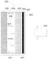
본 발명의 제 4 양태에 따르면 반사기를 냉각시키도록 구성되는 냉각 시스템이 제공되고, 냉각 시스템은 상기 방사선 수집기와 열접촉하는 다공성 구조물로서, 상기 다공성 구조물은 액상 상태의 냉각제를 수용하도록 구성되는, 다공성 구조물, 및 컨덴서로서, 기상 상태에서 냉각제를 상기 다공성 구조물로부터 수용하고, 상기 냉각제를 응축하여 상기 냉각제가 액상 상태로 상변화를 겪도록 하며, 액상 상태의 응축된 냉각제를 상기 다공성 구조물 내로 진입하도록 출력하도록 구성되는, 컨덴서를 포함한다.According to a fourth aspect of the present invention there is provided a cooling system configured to cool a reflector, wherein the cooling system is a porous structure in thermal contact with the radiation collector, the porous structure being configured to receive a liquid coolant, And a condenser for receiving a coolant from the porous structure in a gaseous state and for condensing the coolant to cause the coolant to undergo a phase change to a liquid phase and to output condensed coolant in a liquid phase state into the porous structure And a capacitor.
다공성 구조물은 모세관 구조물이 통과하여 연장되는 재료를 포함할 수도 있다.The porous structure may comprise a material that extends through the capillary structure.
다공성 구조물은 금속을 포함할 수도 있다.The porous structure may comprise a metal.
금속은 구리를 포함할 수도 있다.The metal may comprise copper.
냉각 시스템은 냉각제가 모세관 작용에 의하여 다공성 구조물을 통해 분산되도록 구성될 수도 있다.The cooling system may be configured such that the coolant is dispersed through the porous structure by capillary action.
냉각제는 메탄올을 포함할 수도 있다.The coolant may also comprise methanol.
냉각 시스템은 반사기로부터 다공성 구조물을 밀봉하도록 구성되는 비-다공성 시트를 더 포함할 수도 있다.The cooling system may further include a non-porous sheet configured to seal the porous structure from the reflector.
비-다공성 시트는 구리로 이루어진 비-다공성 시트를 포함할 수도 있다.The non-porous sheet may comprise a non-porous sheet of copper.
냉각 시스템은 리소그래피 장치의 일부를 형성하는 반사기를 냉각시키도록 구성될 수도 있다.The cooling system may be configured to cool the reflector forming part of the lithographic apparatus.
이것은 리소그래피 장치에 대하여 방사원의 방사선 수집기를 냉각하도록 구성될 수도 있다.This may be configured to cool the radiation collector of the radiation source relative to the lithographic apparatus.
본 발명의 제 5 양태에 따르면, 제 4 양태에 따르는 냉각 시스템 및 반사기를 포함하는 장치가 제공되는데, 냉각 시스템은 반사기를 냉각시키도록 구성된다.According to a fifth aspect of the present invention there is provided an apparatus comprising a cooling system and a reflector according to the fourth aspect, wherein the cooling system is configured to cool the reflector.
반사기는 기판을 포함할 수도 있고 냉각 시스템은 기판과 접촉하도록 구성될 수도 있다.The reflector may comprise a substrate and the cooling system may be configured to contact the substrate.
기판은 구리를 포함할 수도 있다.The substrate may comprise copper.
기판은 Al Si-40 을 포함할 수도 있다.The substrate may comprise Al < RTI ID = 0.0 > Si-40.
다공성 계층으로부터 가장 먼 상기 기판의 면에는 평활면을 제공하도록 구성되는 평활층이 제공될 수도 있다.A smoothing layer may be provided that is configured to provide a smooth surface to the surface of the substrate farthest from the porous layer.
평활층은 니켈 인산을 포함할 수도 있다.The smoothing layer may comprise nickel phosphate.
반사기는 리소그래피 장치의 일부를 형성할 수도 있다.The reflector may form part of the lithographic apparatus.
반사기는 제 1 양태에 따르는 방사선 수집기를 포함할 수도 있다.The reflector may comprise a radiation collector according to the first aspect.
본 발명의 제 3 양태의 특징은 본 발명의 제 1 및/또는 제 2 양태의 특징과 결합될 수도 있다.The features of the third aspect of the present invention may be combined with the features of the first and / or second aspect of the present invention.
제 4 양태의 특징은 본 발명의 제 1, 제 2 또는 제 3 양태의 특징과 결합될 수도 있다.The features of the fourth aspect may be combined with the features of the first, second, or third aspect of the present invention.
본 발명의 다른 피쳐 및 장점 및 본 발명의 다양한 실시예의 구조 및 동작은 첨부 도면들을 참조하여 아래에서 상세하게 설명된다. 본 발명이 본 명세서에서 설명되는 특정 실시예로 한정되지 않는다는 것에 주의한다. 이러한 실시예는 본 명세서에서 단지 예시를 위해 제공된다. 본 명세서에 포함된 교시에 기초하여 추가의 실시예가 당업자에게는 명백할 것이다.Other features and advantages of the present invention and the structure and operation of various embodiments of the present invention are described in detail below with reference to the accompanying drawings. It should be noted that the present invention is not limited to the specific embodiments described herein. These embodiments are provided herein for illustrative purposes only. Additional embodiments will be apparent to those skilled in the art based on the teachings contained herein.
본 발명의 실시예는 첨부된 개략적인 도면을 참조하여 오직 예시적인 방식으로 이제 설명될 것이다:
도 1 은 본 발명의 실시예에 따른 리소그래피 장치를 개략적으로 묘사한다;
도 2 는 리소그래피 장치의 더 상세한 도면이다;
도 3 은 방사선 수집기(14)를 포함하는 방사원(SO)의 개략적인 도면이다;
도 4 는 도 3 의 방사선 수집기의 정면도이다;
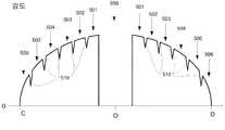
도 5 는 먼 필드(far field) 위치에 입사하고 도 3 및 도 4 의 방사선 수집기에 의하여 반사되는 방사선의 개략적인 도면이다;
도 6a 는 도 3 및 도 4 의 방사선 수집기에서 반사되고 도 5 의 라인 C-D에 입사하는 방사선의 강도의 개략적인 그래프이다;
도 6a 는 방사선 수집기가 수차를 포함할 경우, 도 3 및 도 4 의 방사선 수집기에서 반사되고 도 5 의 라인 C-D에 입사하는 방사선의 강도의 개략적인 그래프이다;
도 7 은 6 개의 반사면을 포함하는 방사선 수집기(141)를 포함하는 방사원(SO)의 개략적인 도면이다;
도 8 은 도 7 의 방사선 수집기에서 반사되고 라인 C-D에 입사하는 방사선의 강도의 개략적인 그래프이다;
도 9 는 방사선 수집기의 대안적 실시예를 포함하는 방사원(SO)의 개략적인 도면이다;
도 10a 는 본 발명의 일 실시예에 따르는 방사선 수집기의 일부의 개략적인 도면이다;
도 10b 는 선행 기술 방사선 수집기의 일부의 개략적인 도면이다;
도 10c 는 본 발명의 대안적 실시예에 따르는 방사선 수집기의 일부의 개략적인 도면이다; 그리고
도 11 은 방사선 수집기를 냉각하도록 구성되는 냉각 시스템의 개략적인 도면이다.
본 발명의 특징 및 장점은 도면과 함께 아래에서 진술되는 발명을 실시하기 위한 구체적인 내용으로부터 더욱 명백해질 것이다. 도면에서, 유사한 부재 번호는 동일하고 기능적으로 유사하며, 및/또는 구조적으로 유사한 요소를 일반적으로 표시한다.Embodiments of the present invention will now be described, by way of example only, with reference to the accompanying schematic drawings in which:
Figure 1 schematically depicts a lithographic apparatus according to an embodiment of the invention;
Figure 2 is a more detailed view of the lithographic apparatus;
Figure 3 is a schematic illustration of a radiation source (SO) comprising a radiation collector (14);
Figure 4 is a front view of the radiation collector of Figure 3;
5 is a schematic illustration of the radiation incident at a far field location and reflected by the radiation collector of FIGS. 3 and 4;
FIG. 6A is a schematic graph of the intensity of the radiation reflected at the radiation collector of FIGS. 3 and 4 and incident on line CD of FIG. 5; FIG.
FIG. 6A is a schematic graph of the intensity of radiation reflected at the radiation collector of FIGS. 3 and 4 and incident on line CD of FIG. 5 when the radiation collector includes aberrations;
Figure 7 is a schematic illustration of a radiation source (SO) comprising a radiation collector (141) comprising six reflective surfaces;
FIG. 8 is a schematic graph of the intensity of the radiation reflected at the radiation collector of FIG. 7 and incident on line CD; FIG.
Figure 9 is a schematic illustration of a radiation source (SO) comprising an alternative embodiment of a radiation collector;
10A is a schematic illustration of a portion of a radiation collector according to an embodiment of the present invention;
Figure 10b is a schematic illustration of a portion of a prior art radiation collector;
Figure 10c is a schematic illustration of a portion of a radiation collector according to an alternative embodiment of the present invention; And
Figure 11 is a schematic illustration of a cooling system configured to cool the radiation collector.
The features and advantages of the present invention will become more apparent from the following detailed description taken in conjunction with the accompanying drawings, in which: FIG. In the drawings, like reference numerals denote the same and functionally similar elements and / or generally denote structurally similar elements.
이러한 발명을 실시하기 위한 구체적인 내용은 본 명세서의 피쳐를 포함하는 하나 이상의 실시예를 개시한다. 개시된 실시예(들)는 본 발명을 단지 예시할 뿐이다. 본 발명의 범위는 개시된 실시예(들)로 한정되지 않는다. 본 발명은 첨부된 청구의 범위에 의하여 정의된다.Specific details for carrying out the present invention disclose one or more embodiments that include the features of the present disclosure. The disclosed embodiment (s) only illustrate the present invention. The scope of the present invention is not limited to the disclosed embodiment (s). The invention is defined by the appended claims.
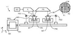
본 발명의 일 실시예에 따르는 도 1 은 본 발명의 일 실시예에 따르는 방사원(SO)을 포함하는 리소그래피 장치(LA)를 개략적으로 도시한다. 이 장치는:1 in accordance with an embodiment of the present invention schematically depicts a lithographic apparatus LA comprising a radiation source SO according to an embodiment of the present invention. This device is:
-방사선 빔(B)(예를 들어 UV 방사선 또는 극자외(EUV) 방사선)을 조절하도록 구성되는 조명 시스템(조명기)(IL);-An illumination system (illuminator) IL configured to condition a radiation beam B (e.g., UV radiation or extreme ultra-violet (EUV) radiation);
-패터닝 디바이스(예를 들어, 마스크 또는 레티클; MA)를 지지하도록 구성되고 패터닝 디바이스를 정확하게 포지셔닝하도록 구성되는 제 1 포지셔너(positioner; PM)에 연결되는 지지 구조(예를 들어 마스크 테이블; MT); -A support structure (e.g., a mask table MT) configured to support a patterning device (e.g., a mask or reticle; MA) and coupled to a first positioner (PM) configured to accurately position the patterning device;
-기판(예를 들어 레지스트-코팅된 웨이퍼; W)을 홀딩하도록 구성되고 기판을 정확하게 포지셔닝하도록 구성되는 제 2 포지셔너(PW)에 연결되는 기판 테이블(예를 들어 웨이퍼 테이블; WT); 및-A substrate table (e.g. a wafer table; WT) coupled to a second positioner PW configured to hold a substrate (e.g., a resist-coated wafer; W) and configured to accurately position the substrate; And
-방사 빔(B)에 부여된 패턴을 패터닝 디바이스(MA)에 의하여 기판(W)의 타겟부(C)(예를 들어 하나 이상의 다이를 포함함)로 투영하도록 구성되는 투영 시스템(예를 들어 반사 투영 시스템)(PS)을 포함한다.-A projection system configured to project a pattern imparted to the radiation beam B onto a target portion C (e.g., including one or more dies) of the substrate W by a patterning device MA Projection system) PS.
조명 시스템(IL)은 방사선을 디렉팅하고, 성형(shaping)하고, 또는 제어하기 위한 다양한 유형의 광 컴포넌트, 예컨대 굴절형, 반사형, 자기적, 전자기, 정전기 또는 다른 유형의 광 컴포넌트, 또는 이들의 임의의 조합을 포함할 수도 있다.The illumination system IL may include various types of optical components for directing, shaping, or controlling radiation, such as refractive, reflective, magnetic, electromagnetic, electrostatic or other types of optical components, And may include any combination.
지지 구조(MT)는 패터닝 디바이스(MA)를, 패터닝 디바이스의 지향, 리소그래피 장치(LA)의 설계, 및 예를 들어 패터닝 디바이스가 진공 환경에서 유지되는지 여부와 같은 다른 조건에 의존하는 방식으로 홀딩한다. 지지 구조(MT)는 패터닝 장치(MA)를 유지하기 위해 기계식, 진공식, 정전식, 또는 기타 클램핑 기술들을 이용할 수 있다. 지지 구조(MT)는 예컨대 필요에 따라 고정되거나 이동시킬 수 있는 프레임(frame) 또는 테이블일 수도 있다. 지지 구조(MT)는 패터닝 디바이스가 예를 들어 투영 시스템(PS)에 대하여 원하는 포지션에 있다는 것을 보장할 수도 있다.The support structure MT holds the patterning device MA in a manner that depends on the orientation of the patterning device, the design of the lithographic apparatus LA, and other conditions such as, for example, whether the patterning device is held in a vacuum environment . The support structure MT may utilize mechanical, vacuum, electrostatic, or other clamping techniques to hold the patterning device MA. The support structure MT may be, for example, a frame or a table that can be fixed or movable as required. The support structure MT may ensure that the patterning device is at a desired position, for example with respect to the projection system PS.
"패터닝 디바이스(MA)"라는 용어는, 기판의 타겟부 내에 패턴을 생성하는 것과 같이, 자신의 단면 내에 패턴을 가지는 방사선 빔을 부여하기 위하여 사용될 수 있는 임의의 디바이스를 지칭하는 것으로 폭넓게 해석되어야 한다. 방사선 빔에 부여된 패턴은 타겟부, 예컨대 집적 회로 내에 생성되는 중인 디바이스 내의 특정 기능성 층에 대응할 수도 있다.The term "patterning device MA" should be broadly interpreted as referring to any device that can be used to impart a beam of radiation having a pattern in its cross-section, such as creating a pattern in a target portion of the substrate . The pattern imparted to the radiation beam may correspond to a particular functional layer in a target portion, e.g., a device being created in an integrated circuit.
패터닝 디바이스(MA)는 투과형 또는 반사형일 수도 있다. 패터닝 장치의 예는 마스크, 프로그램가능 미러 어레이, 및 프로그램가능 LCD 패널을 포함한다. 마스크는 리소그래피에서 주지되며, 이진, 교번 위상-천이, 감쇄 위상-천이, 및 다양한 하이브리드 마스크 타입과 같은 마스크 타입을 포함한다. 프로그램가능 미러 어레이의 일 예는 소형 미러들의 매트릭스 정렬을 채용하는데, 이들 각각은 인입하는 방사선 빔을 상이한 방향으로 반사하기 위하여 개별적으로 틸팅될 수 있다. 틸팅된 미러는 미러 매트릭스에 의하여 반사된 방사선 빔 내에 패턴을 부여한다.The patterning device MA may be transmissive or reflective. Examples of patterning devices include a mask, a programmable mirror array, and a programmable LCD panel. Masks are well known in lithography and include mask types such as binary, alternating phase-shift, attenuated phase-shift, and various hybrid mask types. One example of a programmable mirror array employs matrix alignment of small mirrors, each of which can be individually tilted to reflect the incoming radiation beam in different directions. The tilted mirror imparts a pattern in the beam of radiation reflected by the mirror matrix.
조명 시스템(IL)과 같은 투영 시스템(PS)은 다양한 타입의 광학적 컴포넌트, 예컨대 사용되는 중인 노광 방사선에 대하여, 또는 진공의 사용과 같은 다른 인자에 대해 적합한 바와 같은, 굴절성, 반사성, 자기적, 전자기, 정전기 또는 다른 타입의 광학적 컴포넌트, 또는 이들의 임의의 조합을 포함할 수도 있다. 가스가 EUV 방사선의 상당량을 흡수할 수도 있기 때문에 EUV 방사선에 대해 진공을 사용하는 것이 바람직할 수도 있다. 그러므로 진공 벽 및 진공 펌프의 도움으로 투영 시스템 내의 방사선 빔(B)의 실질적으로 전체 경로에 진공 환경이 제공될 수도 있다.The projection system PS, such as the illumination system IL, may be used to provide various types of optical components, such as refractive, reflective, magnetic, electromagnetic, or other optical components, as appropriate for other factors such as, for example, Electromagnetic, electrostatic or other types of optical components, or any combination thereof. It may be desirable to use a vacuum for EUV radiation because the gas may absorb a significant amount of EUV radiation. Therefore, a vacuum environment may be provided in a substantially entire path of the radiation beam B in the projection system with the aid of a vacuum wall and a vacuum pump.
도시된 것처럼, 장치는 반사형일 수도 있다(예를 들어, 반사형 마스크를 채용).As shown, the device may be of a reflective type (e.g. employing a reflective mask).
리소그래피 장치(LA)는 2개(듀얼 스테이지) 이상의 기판 테이블(WT)(및/또는 2개 이상의 패터닝 디바이스 지지 테이블(MT))을 갖는 유형의 것일 수 있다. 그러한 "다중 스테이지" 기계에서, 하나 이상의 다른 테이블들이 노광을 위해 사용되고 있는 동안 준비 단계들이 하나 이상의 기판 테이블(WT) 상에 수행될 수 있다.The lithographic apparatus LA may be of a type having two (dual stage) or more substrate tables WT (and / or two or more patterning device support tables MT). In such "multiple stage" machines, preparatory steps may be performed on one or more substrate tables WT while one or more other tables are being used for exposure.
도 1 을 참조하면, 조명기(IL)는 극자외 방사선 빔을 방사원(SO)로부터 수광한다. EUV 방사선을 생성하기 위한 방법은, EUV 범위 내에 하나 이상의 방출 라인이 있으면서 재료를 적어도 하나의 원소, 예를 들어, 제논, 리튬 또는 주석을 가지는 플라즈마 상태로 변환하는 단계를 포함하지만 반드시 이것으로 제한되는 것은 아니다. 하나의 이러한 방법에서, 흔히 레이저 생성 플라즈마("laser produced plasma; LPP")라고 명명되는 요구되는 플라즈마는, 연료, 예컨대 요구되는 사전-방출 엘리먼트를 가지는 액적, 스트림, 클러스터를 레이저 빔으로써 조사함으로써 생성될 수 있다. 방사원(SO)은, 연료를 여기하는 레이저 빔을 제공하기 위한, 도 1 에는 도시되지 않는 레이저를 포함하는 EUV 방사선 시스템의 일부일 수도 있다. 결과적으로 얻어지는 플라즈마는, 방사원 내에 배치되는 방사선 수집기에 의하여 수집되는 출력 방사선, 예를 들어 EUV 방사선을 방출한다. 레이저 및 방사원은, 예를 들어 CO2 레이저가 연료 여기를 위한 레이저 빔을 제공하기 위하여 사용되는 경우에 별개의 엔티티들일 수도 있다. 이러한 경우들에서, 레이저는 리소그래피 장치의 일부를 형성하는 것으로 간주되지 않고, 방사선 빔은, 예를 들어 적합한 지향 미러 및/또는 빔 확장기를 포함하는 빔 전달 시스템의 도움으로, 레이저로부터 방사원으로 전달된다.Referring to Fig. 1, the illuminator IL receives an extreme ultraviolet radiation beam from a radiation source SO. The method for generating EUV radiation includes, but is not limited to, converting the material into a plasma state having at least one element, e.g., xenon, lithium or tin, with one or more emission lines in the EUV range It is not. In one such method, the required plasma, often referred to as a "laser produced plasma " (LPP), is generated by irradiating a droplet, stream, or cluster having a desired pre- . The source SO may be part of an EUV radiation system, including a laser, not shown in Fig. 1, for providing a laser beam to excite the fuel. The resulting plasma emits output radiation, e. G. EUV radiation, collected by a radiation collector disposed in the radiation source. The laser and the radiation source may be separate entities, for example when a CO2 laser is used to provide a laser beam for fuel excitation. In these cases, the laser is not considered to form part of the lithographic apparatus, and the radiation beam is transmitted from the laser to the radiation source, for example with the aid of a beam delivery system comprising a suitable directing mirror and / or a beam expander .
흔히 방전 생성 플라즈마("DPP")라고 명명되는 대안적 방법에서, EUV 방출 플라즈마는 연료를 기화시키기 위하여 전기적 방전을 사용함으로써 생성된다. 연료는 EUV 범위에서 하나 이상의 방출 라인을 가지는 제논, 리튬 또는 주석과 같은 원소일 수도 있다. 전기적 방전은 방사원의 일부를 형성할 수도 있거나 방사원으로의 전기적 접속을 통해서 연결되는 별개의 엔티티일 수도 있는 파워 서플라이에 의하여 생성될 수도 있다.In an alternative method, often referred to as a discharge generating plasma ("DPP"), an EUV emission plasma is generated by using electrical discharge to vaporize the fuel. The fuel may be an element such as xenon, lithium, or tin having one or more emission lines in the EUV range. Electrical discharge may form part of a radiation source or may be generated by a power supply, which may be a separate entity connected through an electrical connection to a radiation source.
조명기(IL)는 방사선 빔의 각 세기 분포(angular intensity distribution)를 조절하기 위한 조절기를 포함할 수도 있다. 일반적으로, 조명기(IL)의 퓨필 평면(pupil plane)에서의 세기 분포의 적어도 외측 및/또는 내측 반경 범위(통상적으로, 각각 외측-σ 및 내측-σ라 함)는 조절될 수 있다. 추가적으로, 조명기(IL)는 다면 필드 및 퓨필 미러(facetted field and pupil mirror) 디바이스와 같은 다양한 다른 컴포넌트들을 포함할 수도 있다. 조명기는 방사선 빔이 자신의 단면에서 원하는 균일성 및 세기 분포를 가지도록 조정하기 위하여 사용될 수도 있다.The illuminator IL may comprise a regulator for adjusting the angular intensity distribution of the radiation beam. Generally, at least the outer and / or inner radial extent (commonly referred to as? -Outer and? -Inner, respectively) of the intensity distribution in the pupil plane of the illuminator IL can be adjusted. Additionally, the illuminator IL may include various other components such as a multi-faceted field and a facetted field and pupil mirror device. The illuminator may be used to adjust the radiation beam to have the desired uniformity and intensity distribution in its cross-section.
방사선 빔(B)은 지지 구조(예를 들어, 마스크 테이블)(MT) 상에 홀딩되는 패터닝 디바이스(예를 들어, 마스크)(MA) 상에 입사하고, 그리고 패터닝 디바이스에 의하여 패터닝된다. 패터닝 디바이스(예를 들어 마스크(MA))로부터 반사된 이후에, 방사선 빔(B)은 기판(W)의 타겟부(C) 상에 빔을 포커싱하는 투영 시스템(PS)을 통과한다. 제 2 포지셔너(PW) 및 포지션 센서(PS2)(예를 들어 간섭측정 측정 디바이스, 선형 인코더, 또는 용량성 센서)의 도움을 받아, 예를 들어 방사선 빔(B)의 경로에 상이한 타겟부들(C)을 포지셔닝하기 위하여, 기판 테이블(WT)이 정확하게 이동될 수 있다. 이와 유사하게, 제 1 포지셔너(PM) 및 다른 포지션 센서(PS1)가 패터닝 디바이스(예를 들어, 마스크(MA))를 방사선 빔(B)에 대한 경로에 대하여 정확하게 포지셔닝하기 위하여 사용될 수 있다. 패터닝 디바이스(예를 들어 마스크(MA)) 및 기판(W)은 마스크 정렬 마크(M1, M2) 및 기판 정렬 마크(P1, P2)를 이용하여 정렬될 수 있다.The radiation beam B is incident on a patterning device (e.g., mask) MA, which is held on a support structure (e.g., mask table) MT, and is patterned by a patterning device. After being reflected from the patterning device (e.g., mask MA), the radiation beam B passes through a projection system PS that focuses the beam onto a target portion C of the substrate W. With the aid of a second positioner PW and a position sensor PS2 (e.g. an interference measurement measuring device, a linear encoder or a capacitive sensor) , The substrate table WT can be moved accurately. Similarly, a first positioner PM and another position sensor PS1 may be used to accurately position the patterning device (e.g., mask MA) with respect to the path to the radiation beam B. [ The patterning device (e.g., mask MA) and substrate W may be aligned using mask alignment marks M1 and M2 and substrate alignment marks P1 and P2.
도시된 장치는 다음 모드들 중 하나 이상의 모드로 사용될 수 있다:The depicted apparatus can be used in one or more of the following modes:
1.스텝 모드에서는, 지지 구조(예를 들어, 마스크 테이블(MT) 및 기판 테이블(WT)이 본질적으로 정지 상태로 유지되는 동안, 방사선 빔에 부여된 전체 패턴이 한 번에 타겟부(C) 상에 투영된다(즉, 단일 정적 노광). 그러면, 상이한 타겟부(C)가 노광될 수 있도록 기판 테이블(WT)이 X 방향 및/또는 Y 방향으로 천이된다.One.In step mode, while the support structure (e.g., the mask table MT and the substrate table WT) is kept essentially stationary, the entire pattern imparted to the radiation beam is projected onto the target portion C at one time (I.e., a single static exposure). Then, the substrate table WT is transited in the X and / or Y directions so that a different target portion C can be exposed.
2.스캔 모드에서는, 지지 구조(예를 들어, 마스크 테이블(MT) 및 기판 테이블(WT)이 동기되어 스캐닝되는 동안, 방사선 빔에 부여된 패턴이 타겟부(C) 상에 투영된다(즉, 단일 동적 노광). 지지 구조(예를 들어, 마스크 테이블(MT))에 상대적인 기판 테이블(WT)의 속도 및 방향은 투영 시스템(PS)의 확대율(축소율) 및 이미지 반전 특성에 의하여 결정될 수도 있다.2.In the scan mode, while the support structure (e.g., mask table MT and substrate table WT) is being scanned synchronously, a pattern imparted to the radiation beam is projected onto a target portion C The speed and direction of the substrate table WT relative to the support structure (e.g., mask table MT) may be determined by the magnification (reduction factor) and image reversal characteristics of the projection system PS.
3.다른 모드에서는, 프로그램가능 패터닝 디바이스를 홀딩하면서 지지 구조(예를 들어, 마스크 테이블(MT))은 본질적으로 정지 상태로 유지되고, 기판 테이블(WT)은 방사선 빔에 부여된 패턴이 타겟 영역(C) 상에 투영되는 동안에 이동되거나 스캐닝된다. 이러한 모드에서, 일반적으로 펄스화된(pulsed) 방사선 소스가 채용되며, 프로그램가능한 패터닝 디바이스는 요구될 때, 기판 테이블(WT)의 각 이동 이후에 또는 스캔 도중의 연속적인 방사선 펄스들 사이에서 업데이트된다. 동작의 이러한 모드는 위에서 언급된 바와 같은 타입의 프로그램가능한 미러 어레이와 같은 프로그램가능한 패터닝 디바이스를 이용하는 마스크 없는 리소그래피에 용이하게 적용될 수 있다.3.In another mode, the support structure (e.g., mask table MT) remains essentially stationary while holding the programmable patterning device, and the substrate table WT allows the pattern imparted to the radiation beam to be projected onto the target area C ), As shown in FIG. In this mode, a generally pulsed radiation source is employed and the programmable patterning device is updated after each movement of the substrate table WT, or between successive radiation pulses during a scan, when required . This mode of operation can be readily applied to maskless lithography that utilizes a programmable patterning device, such as a programmable mirror array of a type as referred to above.
또한, 전술한 사용 모드들의 조합 및/또는 변형, 또는 전혀 다른 사용 모드들이 채용될 수도 있다.Combinations and / or variations on the above described modes of use, or entirely different modes of use, may also be employed.
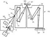
도 2 는 방사원(SO), 조명 시스템(IL), 및 투영 시스템(PS)을 포함하는 리소그래피 장치(LA)를 좀 더 상세하게 도시한다. 방사원(SO)은, 진공 환경이 방사원(SO)의 하우징(2) 내에서 유지될 수 있도록 구성되고 정렬된다.Figure 2 shows the lithographic apparatus LA in more detail, including a radiation source SO, an illumination system IL, and a projection system PS. The radiation source SO is constructed and arranged such that a vacuum environment can be maintained in the
레이저(4)는 레이저 빔(6)을 통해서 레이저 에너지를 유체 방출기(8)로부터 제공되는 주석(Sn) 또는 리튬(Li)과 같은 연료 내로 침착시키도록 구현된다. 액체(즉, 용해된) 주석(액적의 형태일 수도 있음), 또는 액체 형태인 다른 금속은, 현재 가장 성능이 잘 보장되는 것이며 따라서 EUV 방사원에 대한 연료로서 선택될 수 있다고 여겨진다. 지역 연료 내로 레이저 에너지를 침착시키면, 플라즈마 형성 영역(12)에서 고 이온화된 플라즈마를 생성하는데, 이것은 수십 전자 볼트(eV)의 전자 온도를 가진다. 역-여기 및 이러한 이온의 재조합 도중에 발생되는 에너지 방사선은 플라즈마(10)로부터 방출되고, 준수직 입사 방사선 수집기(14)(좀 더 일반적으로는 수직 입사 방사선 수집기라고 흔히 지칭됨)에 의하여 수집되고 집속된다. 도 2 에서 묘사되는 방사선 수집기(14)는 방사선 수집기가 취할 수도 있는 형상의 일 예이다. 방사선 수집기(14)의 다른 실시예는 도 2 에서 묘사되는 방사선 검출기와는 상이하게 성형될 수도 있다. 방사선 수집기(14)의 실시예들은 아래에 상세하게 설명된다. 방사선 수집기(14)는 다중층 구조를 가질 수도 있다. 방사선 수집기(14)는 복수 개의 타원체에 따라서 성형될 수도 있고, 타원체들은 두 개의 초점을 가진다. 하나인 제 1 초점은 플라즈마 형성 영역(12)에 있을 수도 있고, 다른 제 2 초점은 아래에서 논의되는 중간 초점(16)에 있을 수도 있다.The
제 2 레이저(미도시)가 제공될 수도 있는데, 제 2 레이저는 레이저 빔(6)이 그 위에 입사하기 이전에 연료를 예열하도록 구성된다. 이러한 접근법을 사용하는 LPP 소스는 듀얼 레이저 펄싱(dual laser pulsing; DLP) 소스라고 지칭될 수도 있다. 이러한 제 2 레이저는 연료 타겟 내에 사전-펄스를 제공하여, 예를 들어 수정된 타겟을 제공하기 위하여 그러한 타겟의 성질을 변경할 수도 있다. 성질에서의 변화는, 예를 들어 온도 변화, 사이즈, 형상 또는 기타 등등일 수도 있고 일반적으로 타겟의 가열에 의하여 초래될 것이다.A second laser (not shown) may be provided, wherein the second laser is configured to preheat the fuel before the laser beam 6 is incident thereon. An LPP source using this approach may be referred to as a dual laser pulsing (DLP) source. This second laser may provide a pre-pulse in the fuel target, for example to alter the properties of such a target to provide a modified target. The change in properties may be, for example, a temperature change, size, shape or the like, and will generally be caused by heating of the target.
비록 도 1 에는 도시되지 않지만, 연료 방출기는 플라즈마 형성 영역(12)을 향한 궤적을 따라 연료를 디렉팅하도록 구성되는 노즐을 포함하거나 이와 연계될 수도 있다.Although not shown in FIG. 1, the fuel emitter may include or be associated with a nozzle configured to direct fuel along a trajectory towards the
방사선 수집기(14)에 의하여 반사되는 방사선(B)은 포인트(16)에서 집속되어 플라즈마 형성 지역(12)의 이미지를 형성하고, 이것은 이제 조명기(IL)에 대한 방사원으로서 동작한다. 방사선(B)은 복수 개의 서브-빔을 포함할 수도 있다. 방사선(B)이 집속되는 포인트(16)는 일반적으로 중간 초점이라고 지칭되고, 방사원(SO)은 간 초점(16)이 밀폐 구조(2) 내의 개구(18)에 또는 이에 인접하게 위치되도록 정렬된다. 방사선 방출 플라즈마(10)의 이미지는 중간 초점(16)에 형성된다.The radiation B reflected by the
후속하여, 방사선(B)은 조명 시스템(IL)을 가로지르는데, 이것은 패터닝 디바이스(MA)에서 방사선 빔의 원하는 각도 분포 및 패터닝 디바이스(MA)에서의 방사선 강도의 원하는 균일성을 제공하도록 정렬되는 면 필드 미러 디바이스(20) 및 면 동공 미러 디바이스(22)를 포함할 수도 있다. 지지 구조(MT)에서의 방사선의 빔의 반사 시에, 패터닝된 빔(24)이 형성되고, 패터닝된 빔(24)은 반사성 엘리먼트(26, 28)를 통하여 웨이퍼 스테이지 또는 기판 테이블(WT)에 의하여 홀딩되는 기판(W) 상에 투영 시스템(PS)에 의하여 이미징된다.Subsequently, the radiation B traverses the illumination system IL, which is aligned to provide a desired uniform distribution of the radiation intensity at the patterning device MA and the desired angular distribution of the radiation beam at the patterning device MA A surface
도시된 것보다 더 많은 엘리먼트들이 일반적으로 조명 시스템(IL) 및 투영 시스템(PS) 내에 존재할 수도 있다. 더욱이, 도면에 도시된 것보다 더 많은 미러가 존재할 수도 있고, 예를 들어 도 2 에 도시되는 투영 시스템(PS) 내에 존재하는 것보다 1 개 내지 6 개의 추가적 반사성 엘리먼트가 존재할 수도 있다.More elements than shown may generally be present in the illumination system IL and the projection system PS. Moreover, there may be more mirrors than shown in the figure, for example, there may be one to six additional reflective elements than are present in the projection system PS shown in Fig.
EUV 방사선은 대안적으로는 가스 또는 증기, 예를 들어 Xe 가스, Li 증기 또는 Sn 증기에 의하여 생성될 수도 있다. 가스 또는 증기는 플라즈마(10)로 변환되고, 이것이 전자기 스펙트럼의 EUV 범위에서 방사선을 방출한다. 플라즈마(10)는, 예를 들어 적어도 부분적으로 이온화된 플라즈마를 초래하는 전기적 방전에 의하여 생성된다. Xe, Li, Sn 증기 또는 임의의 다른 적합한 가스 또는 증기의 10 Pa의 분압이 방사선을 효율적으로 생성하기 위하여 사용될 수도 있다. 일 실시예에서, 여기된 주석(Sn)의 플라즈마가 EUV 방사선을 생성하기 위하여 제공된다.The EUV radiation may alternatively be generated by gas or vapor, for example Xe gas, Li vapor or Sn vapor. The gas or vapor is converted to
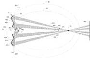
도 3 은, 예를 들어 레이저 생성 플라즈마(LPP) 소스일 수도 있는 방사원(SO)의 일 실시예를 개략적으로 묘사한다. 방사원(SO)은 방사선 수집기(14) 및 오염물 트랩(35)을 포함하는데, 하지만 오염 트랩(35)의 존재는 선택적일 수도 있다. EUV 방사선은 플라즈마 형성 지역(12)으로부터 방출된다. 방사선 수집기(14)는, 방사선 수집기(14)에 의하여 디렉팅되는 방사선이 중간 초점(16)에서 실질적으로 수렴하도록, 플라즈마 형성 지역(12)으로부터 방출된 EUV 방사선을 중간 초점(16)을 향하여 반사하는 반사면을 포함한다. 반사면은 방사선 수집기의 광축(O) 주위에 배치된다. 중간 초점(16)으로부터 바라본 방사선 수집기(14)의 개략적인 묘사가 도 4 에 도시된다.FIG. 3 schematically depicts one embodiment of a radiation source (SO), which may be, for example, a laser-generated plasma (LPP) source. The source SO includes a
방사선 수집기(14)는 방사선 수집기의 광축(O) 주위에 배치되는 면(400, 405 및 410)을 포함한다. 이러한 실시예에서 면(400, 405 및 410)은 원주형으로 광축(O) 주위에서 연장한다. 홀(450)이 방사선 수집기(14)의 중앙에 존재한다. 하나 이상의 레이저 빔(6)(도 2 에 도시된 바와 같은)이 연료를 EUV 방출 플라즈마(10)로 변환시키기 위해서 홀(450)을 통해 통과할 수도 있다. 방사선 수집기(14)의 내측면(400)(즉, 광축(O)에 가장 가까운 면) 및 외측면(405)(즉, 광축(O)으로부터 가장 먼 면)은 각각 내측 타원체(40) 및 외측 타원체(45)에 따라서 성형된다. 내측 타원체(40) 및 외측 타원체(45)는 각각 공통으로 제 1 초점 및 제 2 초점을 가지며, 각각의 경우에 제 1 초점은 플라즈마 형성 지역(12)에 있거나 이에 근접하고 제 2 초점은 중간 초점(16)의 위치에 있거나 이에 근접한다.The
비록 플라즈마 형성 지역(12)에 있거나 이에 근접한 제 1 초점 및 중간 초점(16)의 위치에 있거나 이에 근접한 제 2 초점을 참조하지만, 플라즈마 형성 지역(12) 및 중간 초점(16)이 정밀한 포인트들이 아니고 그들의 중앙으로부터 하나 이상의 차원으로 연장할 수도 있다는 것이 인정되어야 한다. 예를 들어, 플라즈마 형성 지역(12)은 약 600 마이크론의 직경을 가질 수도 있다(EUV 방출 플라즈마는 약 600 마이크론의 직경을 가질 수도 있다). 중간 초점(16)의 범위는 밀폐 구조(2) 내의 개구(18)의 크기에 의하여 제한된다(도 2 를 참조한다). 중간 초점(16)에서 EUV 방사선은 개구(18)의 직경 이하의 빔 웨이스트(beam waist)를 가질 수도 있어서, 중간 초점(16)에서 EUV 방사선의 실질적으로 전부가 개구(18)를 통과하고 조명기(IL) 내로 진행하게 한다. 이것이 EUV 방사선이 조명기(IL)에 진입할 때 EUV 방사선의 손실이 커지는 것을 방지한다. 개구(18)는 약 6 mm의 직경을 가질 수도 있다. 방사선 수집기(141)는 중간 초점(12)에서 형성된 EUV 방출 플라즈마의 이미지가 약 6mm의 직경을 가지도록 구성될 수도 있다. 이미지의 직경은 방사선 수집기(141)에 의하여 제공되는 확대에 의존하는데, 이것은 예를 들어Although reference is made to a second focus at or near the first focus and
sin(각도 번호 582)/sin(각도 번호 580) 또는 sin(각도 번호 583)/sin(각도 번호 581) 로서 계산될 수도 있다. 이미지의 직경은, 예를 들어 중간 초점에서의 상이한 직경 개구(18)(도 2 를 참조한다)를 수용하기 위하여, 방사선 수집기에 의하여 제공되는 확대를 조절함으로써 조절될 수도 있다.sin (angle number 582) / sin (angle number 580) or sin (angle number 583) / sin (angle number 581). The diameter of the image may be adjusted by adjusting the magnification provided by the radiation collector, for example to accommodate different diameter apertures 18 (see FIG. 2) at the intermediate focus.
내측면(400)은 내측 타원체(40)의 부분의 원주와 일치한다. 외측면(405)은 외측 타원체(45)의 부분의 원주와 일치한다. 내측면(400) 및 외측면(405)은 반사면이고 EUV 방사선을 플라즈마 형성 지역(12)으로부터 중간 초점(16)을 향해서 반사한다. 내측 반사면(400)은 EUV 방사선을 반사하여 내측 방사선 서브-빔(500)을 형성하고, 외측 반사면(405)은 EUV 방사선을 반사하여 외측 방사선 서브-빔(505)을 형성한다. 서브-빔(500, 505)은 도 2 에서 묘사되는 방사선 빔(B)을 함께 형성한다.The
내부 및 외측 반사면(400 및 405)은 중간면(410)에 의하여 연결된다. 중간면(410)은 플라즈마 형성 위치(12)로부터 중간면(410)까지의 방향에 실질적으로 평행하게 배치되고, 예를 들어 플라즈마 형성 위치(12)와 반사면의 단부에 교차하는 평면에 의하여 형성된다(도 3 의 단면에 도시된 바와 같음). 그러므로 중간면(410)은 플라즈마 형성 지역(12)으로부터의 EUV 방사선의 전파의 방향에 실질적으로 평행하다. 그러므로 중간면(410)은 그 위에 입사하는 EUV 방사선을 실질적으로 가지지 않는다. 중간면(410)은 가스가 통과해서 방사원(SO)으로 도입될 수도 있는 하나 이상의 홀(도 3 에서 묘사되는 바와 같음)을 포함할 수도 있다. 가스는 가스 소스로부터 도입될 수도 있다. 예를 들어, 가스 소스는 하나 이상의 홀을 통해서 가스를 전달하도록 구성될 수도 있다. 가스 소스는 가스를 중간면(410)으로부터 방사선 수집기(14)의 EUV 반사면을 향해서 전달할 수도 있다. 예를 들어 가스는 수소 가스, 라디칼을 포함하는 가스, 할로겐 가스 또는 불활성 가스일 수도 있다. 가스는 방사선 수집기와 플라즈마 형성 위치(12) 사이에, 연료 및 플라즈마 형성 지역(12)으로부터 유래되는 오염물로부터 방사선 수집기를 보호하는 역할을 할 수도 있는 가스 버퍼를 형성할 수도 있다. 예를 들어 오염물은 가스의 분자와 충돌할 수도 있고, 이것이 오염물이 방사선 수집기(14)에 도달하는 것을 방지할 수도 있다. 추가적으로 또는 대안적으로, 가스는 임의의 오염물을 방사선 수집기(14)의 면으로부터 세척하는 동작을 할 수도 있다.The inner and outer reflecting
방사선 서브-빔(500 및 505)은 먼 필드 위치(200)까지 중간 초점(16)을 통해 지나간다. 예를 들어, 먼 필드 위치(200)는 중간 초점(16)으로부터 약 1 미터의 거리에 포지셔닝될 수도 있다. 도 2 에서 묘사되는 바와 같은 다면 필드 미러 디바이스(20)는 예를 들어 먼 필드 위치(200)에 제공될 수도 있다. 도 5 는 먼 필드 위치(200) 상에 입사하는 EUV 방사선을 개략적으로 묘사한다. 방사선 서브-빔(500 및 505)은 먼 필드 위치(200)에서 실질적으로 원형 내부 및 외부 범위를 가지고, 광축(O) 주위에서 실질적으로 동심이다. 방사선 서브-빔(500 및 505)은 광축(O)과 내측 빔 각도(580) 및 외측 빔 각도(581)를 형성한다(도 3 을 참조한다). 내측 빔 각도(580) 및 외측 빔 각도(581)는 먼 필드 위치(200)에 입사하는 EUV 방사선의 내부 및 외부 범위를 규정한다. 위에서 언급된 바와 같이, 다면 필드 미러 디바이스(20)는 먼 필드 위치(200)에 제공될 수도 있다. 다면 동공 미러 디바이스(22)와 나란한 다면 필드 미러 디바이스(20)는, 원하는 각도 분포 및 방사선 강도의 원하는 균일성을 가지는 방사선 빔을 제공하기 위하여 EUV 방사선을 반사하도록 정렬될 수도 있다. 다면 필드 미러 디바이스(20)는 특정 내측 빔 각도(580) 및 특정한 외측 빔 각도(581)를 가지는 EUV 방사선을 수광하도록 구성될 수도 있다. 일반적으로, 내측 빔 각도(580) 및 외측 빔 각도(581)는 방사원(SO) 및 조명기(IL)의 설계 제한에 의하여 결정될 수도 있다.The
실질적으로 EUV 방사선이 없는 쉐도우 링(510)이 방사선 서브-빔들(500 및 505) 사이에서 연장한다. 실질적으로 EUV 방사선이 없는 중앙 쉐도우 지역(550)은 내측 방사선 서브-빔(500)의 내부 범위에 의하여 둘러싸인다.
도 6a 는 도 5 에서 묘사되는 라인 C-D를 따른, 먼 필드 위치(200) 상에 입사한 EUV 방사선의 강도의 개략적인 그래프이다. 먼 필드 위치(200)에 입사하는 방사선 서브-빔(500 및 505)의 강도는 광축(O)을 향해 갈수록 증가한다. 이것은 플라즈마 형성 지역(12)으로부터의 EUV 방사선의 비-등방성 방출에 기인할 수도 있다. 예를 들어, 플라즈마 형성 지역(12)으로부터 방출된 EUV 방사선의 내측 방사선 수집기 각도(582)에 따른 강도는 외측 방사선 수집기 각도(583)를 따라 방출되는 EUV 방사선의 강도 보다 더 클 수도 있다. 방사선 서브-빔(500 및 505) 사이의 경계 및 먼 필드 위치(200)에서의 쉐도우 링(510)은 도 5 및 도 6a 에서 EUV 방사선의 큰 강도로부터 EUV 방사선이 실질적으로 없는, 그리고 그 반대로의 급격한 천이로서 묘사된다. 그러나 실무상 반사면(400 및 405)은 타원체(40 및 45)의 타원형 형상으로부터 수차를 포함할 수도 있다. 반사면(400 및 405) 내의 수차는 몇몇 EUV 방사선이 쉐도우 링(510)의 에지에 인접하여 쉐도우 링(510) 내로 반사되게 할 수도 있다. 도 6b 는 C-D(도 5 에 역시 도시되는 바와 같음)와 나란한 먼 필드 위치(200)에 입사하는 방사선의 강도의 개략적인 그래프인데, 여기서 반사면(400 및 405)의 수차는 몇몇 EUV 방사선이 쉐도우 링(510) 내로 반사되게 한다.6A is a schematic graph of the intensity of EUV radiation incident on a
다시 도 3 을 참조하면, 오염물 트랩(35)은 플라즈마 형성 지역(12)과 방사선 수집기(14) 사이에 포지셔닝된다. 도 3 에서 묘사되고 이하 설명되는 오염물 트랩(35)은 회전 호일 트랩인데, 하지만 다른 형태의 오염물 트랩이 사용될 수도 있다. 오염물 트랩(35)은 실질적으로 원형 외부 둘레를 가질 수도 있고 도 3 에서 묘사되는 바와 같이 자신의 중심을 통해 연장하는 홀을 가질 수도 있다. 홀은, 연료를 EUV 방출 플라즈마(10)로 변환하기 위하여 하나 이상의 레이저 빔(6)이 오염물 트랩(35)을 통과하도록 할 수도 있다. 오염물 트랩(35)은 홀의 외부 둘레로부터 오염물 트랩(35)의 외부 둘레까지 방사상으로 외부로 연장하는 일련의 호일 날을 포함한다. 오염물 트랩(35)은, 호일 날이 오염물 트랩을 통과하는 오염물과 충돌할 수도 있도록 회전되고, 이를 통하여 오염물을 포획한다.Referring again to Figure 3, the
오염물 트랩(35)은 연료 및 플라즈마 형성 지역(12)으로부터의 오염물을 포획하고, 포획된 오염물이 방사선 수집기(14)에 도달하는 것을 방지하도록 구성된다. 연료 및 플라즈마 형성 지역(12)으로부터의 오염물은 연료의 원자, 이온 및 입자를 포함할 수도 있다. 방사선 수집기(14)에 도달하는 오염물은 방사선 수집기(14)의 반사면(400, 405) 상에 침착될 수도 있고, 반사면의 반사도를 감소시켜서 방사선 수집기(14)에 의하여 반사되는 EUV 방사선의 총량을 감소시킬 수도 있다. 오염물 트랩(35)의 호일 날은 충분히 작은 단면적을 가질 수도 있어서 오염물 트랩(14)을 통과하는 EUV 방사선은 오염물 트랩(35)에 의하여 크게 방해되지 않는다. 그러므로 오염물 트랩(35)은 중간 초점(16) 및 먼 필드 위치(200)로 반사되는 EUV 방사선의 총량을 크게 감소시키지 않는다. 그러나 오염물 트랩(35)은 EUV 방사선을 방해하는 내부 부분(351)을 가질 수도 있다. 내부 부분(351)은, 예를 들어 오염물 트랩(35)을 회전하도록 구성되는 모터 또는 다른 구동 수단을 포함할 수도 있다. 내부 부분(351)은 플라즈마 형성 지역(12)으로부터 방출된 EUV 방사선이 방사선 수집기(14)에 의하여 수집되고 중간 초점(16)으로 반사될 수도 있는 최소 각도인 내측 방사선 수집기 각도(582)를 규정한다. 내측 방사선 수집기 각도는, 예를 들어 약 15 도일 수도 있다. 내측 반사면(400)은 내측 방사선 수집기 각도(582)에서 방사선을 수집하고 방사선을 내측 빔 각도(580)를 따라 중간 초점(16)으로 디렉팅하기 위하여 플라즈마 형성 지역(12)에 충분히 근접하게 포지셔닝된다. 반사면(405)의 외부 범위는 외측 방사선 수집기 각도(583)를 규정하는데, 이것은 플라즈마 형성 지역(12)으로부터 방출되는 EUV 방사선이 방사선 수집기(14)에 의하여 수집되고 중간 초점(16)으로 반사되는 최대 각도이다.The
플라즈마(10)는 매우 고온, 예를 들어 1000oC를 넘는 온도에 도달할 수도 있다. 그러므로 오염물 트랩(35)을 플라즈마 형성 지역(12)으로부터 충분한 거리에 포지셔닝하여, 오염물 트랩(35)이 플라즈마 형성 지역(12)으로부터의, 오염물 트랩(35)을 손상시킬 수도 있는 높은 열부하에 노출되지 않게 하는 것이 바람직하다.The
오염물 트랩(35)에 의하여 포획되는 몇몇 오염물은 후속하여 오염물 트랩(35)으로부터 배출될 수도 있다. 오염물은 임의의 방향으로 배출될 수도 있지만, 특히 오염물 트랩(35)으로부터 방사상으로 외부로 배출될 수도 있다(오염물 트랩의 회전 운동에 기인함). 그러므로 오염물 트랩(35)을 방사선 수집기(14)로부터 충분한 거리에 포지셔닝하여 오염물 트랩(35)으로부터 배출되는 오염물이 실질적으로 오염물이 방사선 수집기(14)에 도달하지 않게 하는 것이 바람직하다. 특히 광축(O)과 나란한 방사선 수집기의 범위와, 광축(O)과 나란한 오염물 트랩(35)의 범위 사이에 축상 중첩이 거의 없거나 전혀 없는 것이 바람직하다(이것이 방사선 수집기 상에 직접적으로 입사하는 방사상으로 배출된 오염을 초래할 것임). 그러므로 방사선 수집기와 플라즈마 형성 위치(12) 사이에 광축(O)과 나란한 이용가능한 길이를 제공하는 것이 바람직한데, 이러한 길이에서 오염물 트랩(35)이 포지셔닝될 수도 있다.Some contaminants trapped by the
오염물 트랩이 포지셔닝될 수도 있는 이용가능한 길이(오염물 트랩 및 방사선 수집기의 임의의 축상 중첩이 존재하지 않음)는 방사선 수집기(14)의 형상 및 포지셔닝에, 그리고 특히 광축(O)과 나란한 방사선 수집기(14)의 깊이(230)에 의존할 수도 있다. 예를 들어 도 3 에서 묘사되고 타원체(40 및 45)에 따라서 성형된 방사선 수집기(14)는, 오염물 트랩(35)이 포지셔닝된 플라즈마 형성 지역(12)과 방사선 수집기(14) 사이에 포지셔닝될 수도 있는 이용가능한 길이(220)를 제공한다. 그러므로 도 3 에서 묘사되는 방사선 수집기(14)와 오염물 트랩(35) 사이에 축상 중첩이 존재하지 않는다.The available lengths (where there is no axial overlap of the contaminant trap and the radiation collector) with which the contaminant trap may be positioned are determined by the shape and positioning of the
방사선 수집기(14)와 플라즈마 형성 지역(12) 사이에 충분한 이용가능한 길이(220)를 제공함으로써, 오염 트랩(35)이 플라즈마(10)로부터의 열부하를 손상시키는 것을 회피하기 위하여 플라즈마 형성 지역(12)으로부터 충분한 거리에, 그리고 방사선 수집기(14)와 오염물 트랩(35) 사이에 축상 중첩이 존재하지 않도록 방사선 수집기(14)로부터 충분한 거리에 포지셔닝될 수도 있게 하는 것이 바람직하다. 그러므로 도 3 에서 묘사되고 두 개의 타원체(40 및 45)에 따라서 성형되는 방사선 수집기(14)는, 이것이 내부 및 외측 빔 각도(580 및 581)를 유지하고 내측 방사선 수집기 각도(582)에서 방사선을 수집하면서, 플라즈마 형성 지역(12)과 방사선 수집기(14) 사이에 충분한 이용가능한 길이(220)를 제공한다는 점에 있어서 유리하다.Forming
도 3 에서 묘사되는 실시예에 의하여 제공되는 이용가능한 길이(220)는, 단일 반사면을 포함하는 선행 기술 방사선 수집기와 비교할 때 유리하다. 이러한 선행 기술 방사선 수집기는 단일 타원체에 따라서 성형될 것이고, 본 발명의 일 실시예에 따른 방사선 수집기보다 광축(O)을 따라 더 큰 깊이를 가질 것이다. 이러한 선행 기술 방사선 수집기는 오염물 트랩이 포지셔닝될 수도 있는 충분한 이용가능한 길이를 플라즈마 형성 지역(12)과 방사선 수집기 사이에 제공하지 않을 수도 있다. 예를 들어, 단일 반사면을 포함하는 방사선 수집기는 도 3 에서 묘사되는 방사선 수집기(14)와 동일한 각도 범위에서 EUV 방사선을 수집하도록 구성될 수 있다. 이러한 방사선 수집기는, 예를 들어 타원체(40)에 따라서 성형된 단일 반사면을 포함할 수 있다. 그러나 이러한 방사선 수집기는, 동일한 각도 범위에서 방사선을 수집하고, 광축(O)으로부터 벗어나서 타원체(40) 주위에서 연장하여, 이를 통하여 방사선 수집기의 깊이(230)를 증가시키고 이용가능한 길이(220)를 감소시킬 것이다. 방사선 수집기가 도 3 에서 묘사되는 외측 빔 각도(580)와 동일한 외측 빔 각도를 가지는 EUV 방사선을 제공하기 위하여, 반사면(400)은 타원체(40) 주위에서 연장하여 이것이 광축(O)을 따라서 플라즈마 형성 지역(12)을 넘어 연장하게 할 필요가 있을 것이다. 그러므로 오염물 트랩(35)을 포지셔닝하기 위한 길이가 방사선 수집기(14)와 플라즈마 형성 지역(12) 사이에 제공되지 않을 것이다. 오염물 트랩이 제공되어야 한다면, 수집기(14)와 오염물 트랩(35) 사이에 축상 중첩이 존재할 것이다. 이것은 오염물 트랩으로부터 방사상으로 배출된 오염이 수집기에 입사하게 할 것이다. 이러한 문제점은 본 발명의 실시예에 의하여 회피된다.The
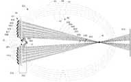
본 발명의 일 실시예에 따르는 방사선 수집기는 세 개 이상의 반사면을 포함할 수도 있다. 세 개 이상의 반사면의 각각은 상이한 타원체의 부분과 일치할 수도 있다. 도 7 은 방사선 수집기(141)를 포함하는 본 발명의 일 실시예에 따르는 방사원(SO)을 개략적으로 묘사한다. 방사선 수집기(141)는 성형된 6 개의 반사면(400 내지 405)을 포함하고, 여기에서 반사면(400 내지 405)의 각각은 6 개의 타원체(40 내지 45) 중 하나와 일치한다. 실시예에서, 타원체(40 내지 45) 모두는 공통으로 제 1 타원 초점 및 제 2 타원 초점을 가진다. 각각의 경우에 제 1 초점은 플라즈마 형성 지역(12)에 있거나 이에 근접하고 제 2 초점은 중간 초점(16)의 위치에 있거나 이에 근접한다. 반사면은 방사선 수집기의 광축(O) 주위에 배치된다. 반사면(400 내지 405)은 광축(O) 주위에서 실질적으로 원주형으로 연장한다.The radiation collector according to an embodiment of the present invention may include three or more reflective surfaces. Each of the three or more reflective surfaces may coincide with a portion of a different ellipsoid. 7 schematically depicts a radiation source SO according to one embodiment of the present invention including a
반사면(400 내지 405)은 일련의 중간면(410)에 의하여 연결된다. 각각의 중간면(410)은 플라즈마 형성 위치(12)로부터 중간면(410)까지의 방향에 실질적으로 평행하게 배치된다. 그러므로 중간면(410)은 플라즈마 형성 지역(12)으로부터의 EUV 방사선의 전파의 방향에 실질적으로 평행하다. 그러므로 중간면(410)은 그들 위에 입사하는 EUV 방사선을 실질적으로 가지지 않는다. 하나 이상의 홀이 중간면(410) 중 하나 이상에 제공될 수도 있고(도 7 에서 묘사되는 바와 같이), 이것을 통해서 가스가 도입될 수도 있다. 가스는 방사선 수집기(141)를 연료 및 플라즈마 형성 지역(12)으로부터 유래하는 오염물로부터 보호하는 역할을 할 수도 있는 수소 가스일 수도 있다. 추가적으로 또는 대안적으로, 가스는 임의의 오염물을 방사선 수집기(141)의 면으로부터 세척하는 역할을 할 수도 있다. 가스는 가스 소스(미도시)에 의하여 하나 이상의 홀을 통해 전달될 수도 있으며, 가스 소스는 하나 이상의 홀을 통해서 가스를 전달하도록 구성된다.The reflecting surfaces 400 to 405 are connected by a series of
반사면(400 내지 405)은 EUV 방사선을 반사하여 방사선 서브-빔(500 내지 505) 각각을 형성한다. 방사선 서브-빔(500 내지 505)은 중간 초점(16)을 통과하고 먼 필드 위치(200)에 입사한다. 방사선 서브-빔(500 내지 505)은 광축(O)과 내측 빔 각도(580) 및 외측 빔 각도(581)를 형성한다. 내측 빔 각도(580) 및 외측 빔 각도(581)는 먼 필드 위치(200)에 입사하는 EUV 방사선의 내부 및 외부 범위를 규정한다.The reflecting surfaces 400 to 405 reflect the EUV radiation to form each of the radiation sub-beams 500 to 505. The radiation sub-beams 500 through 505 pass through the
도 7 에서 묘사되는 방사선 수집기(141)는 도 3 에서 묘사되는 방사선 수집기(14)와 동일한 각도 범위에 걸쳐 EUV 방사선을 수집한다(내측 방사선 수집기 각도(582)와 외측 방사선 수집기 각도(583) 사이에서). 방사선 수집기(141)는 또한 EUV 방사선을 반사하여, 방사선 수집기(14)에 의하여 형성되는 방사선 서브-빔(500, 505)과 동일한 내측 빔 각도(580) 및 동일한 외측 빔 각도(581)를 광축(O)과 형성하는 방사선 서브-빔(500 내지 505)을 형성한다. 그러므로 방사선 수집기(141)에 의하여 수집되는 EUV 방사선은 방사선 수집기(14)에 의하여 수집되는 EUV 방사선과 동일한 내부 및 외부 범위를 먼 필드 위치(200)에서 가진다. 그러나 방사선 수집기(141)는 방사선 수집기(14)보다 더 작은 깊이(230)를 광축(O)을 따라 가진다. 더 작은 깊이(230)는 그 안에 오염물 트랩(35)이 포지셔닝될 수도 있는, 플라즈마 형성 지역(12)과 방사선 수집기 사이의 길이(220)를 증가시킬 수도 있다.The
도 8 은 라인 C-D(도 5 를 참조한다)에 따라서 먼 필드 위치(200)에 입사하는, 방사선 수집기(141)에 의하여 수집되는 EUV 방사선의 강도의 개략적인 그래프이다. 방사선 강도 분포는 실질적으로 EUV 방사선이 존재하지 않는 중앙 쉐도우 지역(550)을 포함한다. 쉐도우 링(510)은 방사선 서브-빔들(500 내지 505) 사이에서 연장한다. 쉐도우 링(510)은 그 위에 EUV 방사선이 실질적으로 입사하지 않고 따라서 그로부터 EUV 방사선이 실질적으로 반사되지 않는 방사선 수집기(141)의 중간면(410)에 의하여 야기된다. 쉐도우 링(510)은 도 8 에서 보이는 바와 같은 트로프(trough)가 EUV 방사선 강도에서 생기게 한다. 그러나, 반사면의 수차는 일부 EUV 방사선이 쉐도우 링(510) 내로 반사되게 한다. 방사선 수집기(141)의 중간면은 충분히 짧고, 따라서 쉐도우 링(510)이 충분히 작은 방사상 범위를 가져서, 쉐도우 링(510) 내로 반사되는 EUV 방사선이 쉐도우 링(510)에 의하여 야기되는 EUV 방사선 강도 내의 트로프가 제로로 떨어지지 않게 한다.8 is a schematic graph of the intensity of EUV radiation collected by the
일반적으로 방사선 수집기로부터 반사된 방사선 강도 내의 트로프의 폭 및 깊이는 방사선 수집기의 반사면을 연결하는 방사선 수집기의 중간면의 길이를 감소시킴으로써 감소될 수도 있다. 중간면의 길이는, 방사선 수집기를 형성하는 반사면의 개수를 증가시키고 그러므로 방사선 수집기의 반사면이 일치하는 타원체의 개수를 증가시킴으로써 감소될 수도 있다.In general, the width and depth of the troughs in the radiation intensity reflected from the radiation collector may be reduced by decreasing the length of the median surface of the radiation collector connecting the reflecting surfaces of the radiation collector. The length of the intermediate surface may be reduced by increasing the number of reflecting surfaces that form the radiation collector and therefore increasing the number of ellipsoids to which the reflecting surface of the radiation collector coincides.
예를 들어, 방사선 수집기(14)(도 3 에서 묘사됨)은 두 개의 타원체(40 및 45)들 중 하나와 각각 일치하는 두 개의 반사면(400 및 405)을 포함한다. 반사면(400, 405)을 연결하는 중간면(410)은, 큰 트로프가 방사선 수집기(14)로부터 초래되는 방사선 강도 분포 범위 내에 야기되게 하는 충분히 큰 방사선 범위를 가지는 쉐도우 링(510)이 발생하도록 한다(도 6b 에서 묘사됨). 이에 반해, 방사선 수집기(141)(도 7 에서 묘사됨)는 개의 타원체(40 내지 45)들 중 하나와 각각 일치하는 6 개의 반사면(400 내지 405)을 포함한다. 그러므로 방사선 수집기(141)의 반사면(400 내지 405)을 연결하는 중간면(410)은 방사선 수집기(14)의 반사면(400, 405)을 연결하는 중간면(410) 보다 더 짧다. 결과적으로, 방사선 수집기(141)에 의하여 형성되는 쉐도우 링(410)은 방사선 수집기(14)에 의하여 형성되는 쉐도우 링보다 더 작은 방사상 범위를 가진다. 그러므로 방사선 수집기(141)로부터 반사된 방사선 강도 분포 내의 트로프는 방사선 수집기(14)로부터 반사된 방사선 강도 분포 내의 트로프보다 더 좁고 더 얕다.For example, the radiation collector 14 (depicted in FIG. 3) includes two
먼 필드 위치(200)에서 실질적으로 평평한 방사선 강도 분포(중앙 쉐도우 지역의 양측)를 가지는 EUV 방사선을 제공하는 것이 바람직할 수도 있다. 이것은, 예를 들어 다면 필드 미러 디바이스(20) 및 다면 동공 미러 디바이스(22)가 방사선 강도의 원하는 각도 분포 및 원하는 균일성을 가지는 방사선 빔을 제공하게 할 수도 있다. 방사선 수집기의 반사면의 개수를 증가시키고 그러므로 방사선 수집기가 그에 따라 성형되는 타원체의 개수를 증가시키면, 결국 방사선 수집기로부터 반사된 방사선 강도 분포 내의 임의의 트로프의 폭 및 깊이를 감소시켜서 트로프가 무시될 수 있게 할 수도 있다. 그러므로 큰 트로프를 포함하지 않는 실질적으로 평평한 방사선 강도 분포는, 많은 타원체에 따라서 성형된 많은 반사면으로부터 방사선 수집기를 형성함으로써 획득될 수도 있다. 예를 들어, 방사선 수집기는 7 개 이상의 타원체에 따라서 성형된 7 개 이상의 반사면을 포함할 수도 있다(즉, 도 7 에 도시되는 것보다 더 많음). 예를 들어, 방사선 수집기의 몇몇 실시예는 11개 이상의 타원체에 따라서 성형된 11개 이상의 반사면을 포함할 수도 있다. 예를 들어, 방사선 수집기의 몇몇 실시예는 31개 이상의 타원체에 따라서 성형된 31개 이상의 반사면을 포함할 수도 있다. 위에서 언급된 바와 같이, 반사면의 개수를 증가시키면, 반사면으로부터 반사된 방사선 사이의 트로프가 감소되게 하는 장점을 제공한다. 반사면의 개수에 대한 실무상 한정은 방사선 수집기(141)가 방사선으로부터 수신하는 최대 각도(583)(이것은 방사선 수집기의 개구각(583)이라고 지칭될 수도 있음)에 특정 각도 범위에 걸쳐 제공될 수도 있는 반사면의 개수에 대한 제조 한계를 결합하여 발생할 수도 있다.It may be desirable to provide EUV radiation having a substantially flat radiation intensity distribution (both sides of the central shadow region) at the
EUV 방사선에 추가하여, 방사선 수집기는 또한 적외선 방사선 또는(D)UV 방사선에 노출될 수도 있다. 적외선 방사선은 연료를 EUV 방출 플라즈마(10)로 변환하기 위하여 사용되는 하나 이상의 적외선 레이저로부터 유래할 수도 있다. 적외선 방사선은 방사선 수집기에 의하여 반사되고 중간 초점(16)을 통해 먼 필드 위치(200)로 디렉팅될 수도 있다. 먼 필드 위치(200)에 도달하는 적외선 방사선은 리소그래피 장치의 컴포넌트의 바람직하지 않은 가열을 야기할 수도 있다. 그러므로 방사선 수집기에 의하여 반사되고 중간 초점(16)을 향해서 디렉팅되는 임의의 적외선 방사선을 감소시키는 것이 바람직할 수도 있다. 이것은 방사선 수집기의 반사면에 홈 또는 마루를 형성하여 반사면이 적외선 방사선에 대한 회절 격자로서 동작하고 따라서 적외선 방사선을 중간 초점(16)을 향해서 거의 반사하지 않게 함으로써 획득될 수도 있다.In addition to EUV radiation, the radiation collector may also be exposed to infrared radiation or (D) UV radiation. The infrared radiation may be from one or more infrared lasers used to convert the fuel into an
본 발명의 일 실시예에 따르면, 방사선 수집기의 반사면은 방사선 수집기가 적외선 방사선에 대한 회절 격자로서 동작하게 하는 길이를 가질 수도 있다. 반사면의 길이가 거의 적외선 방사선의 파장인 경우, 방사선 수집기는 적외선 방사선에 대한 회절 격자로서 동작할 수 있다. EUV 방사선의 파장이 적외선 방사선의 파장보다 훨씬 더 짧기 때문에, 반사면 및 중간면의 길이는, 방사선 수집기가 EUV 방사선을 중간 초점(16)을 향해서 반사하지만 적외선 방사선에 대한 회절 격자로서 동작하며, 따라서 중간 초점(16)을 향해서 적외선 방사선을 거의 반사하지 않게 하는 것일 수도 있다. 예를 들어 이러한 방사선 수집기는 거의 적외선 방사선의 파장인 길이를 가지는 반사면을 포함할 수도 있다. 중간면은 또한 거의 적외선 방사선의 파장인 길이를 더 가질 수도 있다.According to one embodiment of the invention, the reflecting surface of the radiation collector may have a length which allows the radiation collector to act as a diffraction grating for the infrared radiation. If the length of the reflective surface is close to the wavelength of the infrared radiation, the radiation collector may act as a diffraction grating for the infrared radiation. Since the wavelength of the EUV radiation is much shorter than the wavelength of the infrared radiation, the lengths of the reflecting and intermediate surfaces operate as a diffraction grating for the infrared radiation, although the radiation collector reflects the EUV radiation towards the
도 3 및 도 7 각각에 묘사되는 방사선 수집기(14 및 141)는 양자 모두 복수 개의 반사면(400 내지 405)을 포함하는데, 여기에서 복수 개의 반사면의 각각은 복수 개의 타원체(40 내지 45)들 중 하나와 일치한다. 복수 개의 타원체(40 내지 45)는 공통으로 제 1 초점 및 제 2 초점을 가진다. 플라즈마 형성 위치(12) 및 제 2 초점에 있거나 이에 근접하는 제 1 초점은 중간 초점(16)에 있거나 이에 근접한다. 복수 개의 반사면(400 내지 405)은 제 1 초점으로부터의 방사선을 수신하고 이러한 방사선을 제 2 초점으로 반사하도록 구성된다. 복수 개의 반사면(400 내지 405)은 하나 이상의 중간면(410)에 의하여 연결된다. 각각의 중간면(410)은 제 1 초점으로부터 중간면(410)까지의 방향에 실질적으로 평행하게 배치된다. 광축(O)으로부터의 복수 개의 반사면의 거리는, 각각의 반사면이 일치하는 타원체의 크기와 함께 증가한다. 따라서, 복수 개의 반사면의 내측 반사면(400)은 복수 개의 타원체 중 내측 타원체(40)와 일치한다.Both the
방사선 수집기(14 및 141)는 광축(O)을 따라 깊이(230)를 가진다. 방사선 수집기(14 및 141)는 방사선 수집기의 깊이(230)를 감소시키도록 성형된다. 방사선 수집기(14 및 141)는 결과적으로 단일 타원체에 따라서 성형된 단일 반사면을 포함하는 방사선 수집기보다 더 평평한 프로파일을 가진다. 방사선 수집기(14 및 141)는, 오염물 트랩(35)이 방사선 수집기와 제 1 및 제 2 초점들 사이에 포지셔닝될 수도 있는, 광축(O)과 나란한 이용가능한 길이(220)가 제공되도록 구성된다. 일반적으로, 방사선 수집기가 더 많은 반사면을 포함할수록, 방사선 수집기의 획득가능한 깊이(230)는 더 작아지고 이것의 프로파일을 더 평평해진다(주어진 방사선 수집기 및 빔 각도에 대하여). 일반적으로, 획득가능한 깊이(230)가 더 작을수록, 이용가능한 길이(220)는 더 커진다.The
그러나 본 발명의 일 실시예에 따르는 방사선 수집기는 실질적으로 비-평평한 프로파일을 가지도록 성형될 수도 있다.However, the radiation collector according to one embodiment of the present invention may be shaped to have a substantially non-flat profile.
도 9 는 실질적으로 비-평평한 프로파일을 가지는 방사선 수집기(241)를 포함하는 방사원(SO)의 일 실시예를 개략적으로 묘사한다. 방사선 수집기(241)는 타원체(60 내지 65)에 따라서 성형된다. 일 실시예에서, 타원체들(60 내지 65)은 모두 공통으로 제 1 초점 및 제 2 초점을 가지며, 각각의 경우에 제 1 초점은 플라즈마 형성 지역(12)에 있거나 이에 근접하고 제 2 초점은 중간 초점(16)의 위치에 있거나 이에 근접한다. 방사선 수집기(241)는 타원체(60 내지 65) 각각과 일치하는 반사면(600 내지 605)을 포함한다.Figure 9 schematically depicts one embodiment of a radiation source (SO) that includes a radiation collector (241) having a substantially non-flat profile. The
반사면(600 내지 605)은 각각 EUV 방사선을 반사하여 방사선 서브-빔(700 내지 705) 각각을 형성한다. 방사선 서브-빔(700 내지 705)은 중간 초점(16)을 통과하고 먼 필드 위치(200)에 입사한다. 방사선 서브-빔(700 내지 705)은 광축(O)과 내측 빔 각도(580) 및 외측 빔 각도(581)를 형성한다.The
도 9 에서 묘사되는 실시예에서, 타원체(65)는 도 3 및 도 7 에서 묘사되는 타원체(40)와 동일하다. 그러므로 반사면(600)은 반사면(400)과 동일한 내측 방사선 수집기 각도(582)에서 방사선을 수집한다. 내측 방사선 서브-빔(700)은 또한 내측 방사선 서브-빔(500)과 동일한 내측 빔 각도(580)를 광축과 형성한다. 방사선 수집기(241)는 외측 방사선 수집기 각도(584)까지 그리고 이를 포함하여 EUV 방사선을 수집하도록 연장함으로써, 외측 방사선 서브-빔(705)이 외측 방사선 서브-빔(505)과 동일한 외측 빔 각도(581)를 광축과 형성하게 한다. 그러므로 방사선 수집기(241)는 먼 필드 위치(200)에서 방사선 수집기(14 및 141)에 의하여 형성된 방사선 서브-빔(500 내지 505)과 동일한 내부 및 외부 범위를 가지는 방사선 서브-빔(700 내지 705)을 형성한다.In the embodiment depicted in FIG. 9, the
반사면은 일련의 중간면(610)에 의하여 연결된다. 각각의 중간면(610)은 중간 초점(16)으로부터 중간면(610)까지의 방향에 실질적으로 평행이다. 그러므로 각각의 중간면은 중간 초점(16)을 향하여 반사면(600 내지 605)에 의하여 반사되었던 EUV 방사선의 전파의 방향에 실질적으로 평행이다. 그러므로 중간면(610)은, 후속하여 중간 초점(16)으로 반사되지 않는, 그 위에 입사하는 플라즈마 형성 지역(12)으로부터의 EUV 방사선을 가진다. 이것은 방사선 수집기(14 및 141)로부터 중간 초점(16)으로 반사된 EUV 방사선과 비교하여 중간 초점(16)에서 EUV 방사선의 일부 손실을 야기할 수도 있다. 그러나 방사선 수집기(241)는 방사선 수집기(14 및 141) 보다 더 큰 각도 범위에 걸쳐서 플라즈마 형성 지역(12)으로부터 방사선을 수집한다. 방사선 수집기(241)의 수집의 각도 범위가 더 크기 때문에 방사선 수집기(241)의 중간면(610)에 기인하여 손실되는 임의의 EUV 방사선을 보상할 수도 있다.The reflective surface is connected by a series of
중간면(610)은 가스가 통과하여 도입될 수도 있는 하나 이상의 홀을 중간면(610)(도 9 에서 묘사되는 바와 같음) 내에 포함할 수도 있다. 가스는 방사선 수집기(241)를 연료 및 플라즈마 형성 지역(12)으로부터 유래하는 오염물로부터 보호하는 역할을 할 수도 있는 수소 가스일 수도 있다. 추가적으로 또는 대안적으로, 가스는 임의의 오염물을 방사선 수집기(241)의 면으로부터 세척하는 역할을 할 수도 있다. 가스는 가스 소스에 의하여 하나 이상의 홀을 통해 전달될 수도 있다.The
중간면(610)이 반사면(600 내지 605)으로부터 반사된 EUV 방사선의 전파의 방향과 실질적으로 평행하기 때문에, 방사선 서브-빔(700 내지 705)은 그들 사이에 쉐도우 링을 실질적으로 가지지 않는다. 먼 필드 위치(200)(중앙 쉐도우 지역(750)의 양측)에서의 EUV 방사선의 강도 분포는, 따라서 실질적으로 연속이다.Since the
방사선 수집기(241)는 방사선 수집기(14 및 141)에 비하여 상이한 형상을 가진다. 각각의 중간면(610)은 제 2 초점(중간 초점의 위치에 있거나 이에 근접함)으로부터의 중간면(610)까지의 방향에 실질적으로 평행하게 배치된다. 광축(O)으로부터의 복수 개의 반사면(600 내지 605)의 거리는, 각각의 반사면이 일치하는 타원체의 크기와 함께 감소한다. 따라서, 복수 개의 반사면의 내측 반사면(600)(즉, 광축(O)에 가장 근접한 것)은 복수 개의 타원체 중 외측 타원체(600)와 일치한다.The
방사선 수집기(14 및 141)에 비하여 방사선 수집기(241)의 형상이 실질적으로 상이하다는 것은 결과적으로, 플라즈마 형성 지역(12)으로부터의 EUV 방사선이 개별적인 방사선 수집기의 반사면과 형성하는 입사 및 반사각이 실질적으로 상이하게 한다. 반사면의 반사성은 반사면 상에 입사하는 방사선의 입사각의 함수로서 변동할 수도 있다. 예를 들어, 반사면은 입사각이 직각에 근접할 경우 가장 반사도가 높을 수도 있다. EUV 방사선이 방사선 수집기(14 및 141)의 반사면과 형성하는 입사각은 EUV 방사선이 방사선 수집기(241)의 반사면과 형성하는 입사각보다 직각에 더 가까울 수도 있다. 그러므로 방사선 수집기(14 및 141)의 형상과 균등한 형상을 가지는 방사선 수집기는, 방사선 수집기(241)의 형상과 균등한 형상을 가지는 방사선 수집기 보다 EUV 방사선을 플라즈마 형성 지역(12)으로부터 반사할 수도 있다.The fact that the shape of the
방사선 수집기(14 및 141)는, 오염물 트랩(35)이 포지셔닝될 수도 있는 이용가능한 길이(220)를 플라즈마 형성 지역(12)과 방사선 수집기(14 및 141) 사이에 허용한다. 그러나 방사선 수집기(241)는 플라즈마 형성 지역(12)과 방사선 수집기(241) 사이에 이용가능한 길이를 허용하지 않는다. 그러므로 오염물 트랩이 플라즈마 형성 지역(12)과 방사선 수집기(241) 사이에 포지셔닝되어야 하는 경우, 오염물 트랩은 방사선 수집기(241)와 축상으로 중첩할 것이다. 결과적으로, 방사상 방향으로 오염물 트랩에 의하여 배출되는 임의의 오염(이것은 오염물 트랩의 회전에 기인하여 발생할 수도 있음)이 방사선 수집기(241)에 입사할 것이다.The
EUV 방사선을 내측 방사선 수집기 각도(582)와 외측 방사선 수집기 각도(583, 584) 사이에서 수집하고 EUV 방사선을 방사선 서브-빔으로 반사하여 광축(O)과 내측 빔 각도(580) 및 외측 빔 각도(581)를 형성하는 본 발명의 실시예가 설명되었다. 그러나 본 발명의 다른 실시예는 위에서 설명되고 도면에 도시된 것들과는 다른 내부 및 외측 방사선 수집기 각도 및 내부 및 외측 빔 각도를 가질 수도 있다. 이러한 각도는 먼 필드 위치(200)에 입사하는 방사선의 원하는 내부 및 외부 범위에 따라서 그리고 방사선 수집기의 상대적인 기하학적 구조, 중간 초점(16) 및 먼 필드 위치(200)에 따라서 결정될 수도 있다. 예를 들어 먼 필드 위치(200) 및/또는 중간 초점(16)이 광축(O)을 따라 방사선 수집기에 상대적으로 이동된다면, 먼 필드 위치(200)에 입사하는 방사선의 내부 및 외부 범위를 유지하기 위하여 내부 및 외측 빔 각도를 변경하는 것이 바람직할 수도 있다. 몇몇 본 발명의 실시예에 추가적으로 또는 대안적으로, 먼 필드 위치(200)의 구성에 따라서 먼 필드 위치(200) 상에 입사하는 방사선의 내부 및 외부 범위를 변경하는 것이 바람직할 수도 있다. 일반적으로 내측 빔 각도(580), 외측 빔 각도(581), 내측 방사선 수집기 각도(582) 및 외측 방사선 수집기 각도(583, 584)는 결정되고 방사원(SO) 및 조명기(IL)의 디자인에 의하여 제한될 수도 있다. 그러므로 이러한 각도는 방사원(SO) 및 조명기(IL)의 설계 제한 사항을 만족시키기 위하여 방사선 수집기의 설계를 변경함으로써 변경될 수도 있다.The EUV radiation is collected between the inner
위에서 설명된 바와 같이, 적외선 방사선은 EUV 방사원(SO) 내의 방사선 수집기(예를 들어 도 2, 도 3, 도 7 및 도 9 에서 묘사되는 방사선 수집기(14, 141, 241))에 입사할 수도 있다. 예를 들어, 하나 이상의 적외선 레이저(예를 들어 CO2 레이저)는 연료를 여기시켜서 EUV 방출 플라즈마를 형성하기 위하여 플라즈마 형성 위치(12)에 입사할 수도 있다. 하나 이상의 적외선 레이저로부터의 적외선 방사선 중 일부는 플라즈마 형성 위치(12)에서 플라즈마 및/또는 연료에 의하여 반사되어 방사선 수집기에 입사할 수도 있다. 방사선 수집기에 입사하는 적외선 방사선의 부분은 방사선 수집기에 의하여 중간 초점(16)을 향해 반사할 수도 있다. 중간 초점(16)을 향해 반사되는 적외선 방사선은 조명 시스템(IL)(도 2 에서 묘사됨)에 진입할 수도 있고, 후속하여 리소그래피 장치(LA)의 다른 광학적 컴포넌트로 반사될 수도 있다.As described above, the infrared radiation may be incident on a radiation collector (e.g., the
중간 초점(16)을 향해서 반사되고 조명 시스템(IL)에 진입하는 적외선 방사선은 조명 시스템(IL) 내의 광학적 컴포넌트에 의하여 및/또는 리소그래피 장치(LA)의 다른 광학적 컴포넌트에 의하여 흡수될 수도 있다. 광학적 컴포넌트에 의한 적외선 방사선의 흡수는 이러한 광학적 컴포넌트가 적외선 방사선에 의하여 가열되게 할 수도 있다. 광학적 컴포넌트가 가열되면 광학적 컴포넌트의 전부 또는 일부의 팽창이 일어날 수도 있고, 이것이 광학적 컴포넌트의 광학적 성질을 변경할 수도 있다. 광학적 컴포넌트의 광학적 성질이 변경되면 리소그래피 장치를 통과하여 전파되는 EUV 방사선 빔에 영향을 줄 수도 있고, 궁극적으로 패터닝된 EUV 방사선 빔에 의하여 기판(W)에 적용되는 패턴에 영향을 줄 수도 있다.The infrared radiation reflected toward the
그러므로 방사선 수집기에 의하여 중간 초점(16)을 향하여 반사되는 적외선 방사선의 양을 감소시켜서 리소그래피 장치의 광학적 컴포넌트에 입사하는 적외선 방사선의 양이 감소되게 하는 것이 바람직하다. 도 2, 도 3, 도 7 및 도 9 에서 묘사되는 방사선 수집기(14, 141, 241)의 실시예에서, 중간 초점(16)을 향하여 반사되는 적외선 방사선의 양은 방사선 수집기(14, 141, 241)가 적외선 방사선에 대한 회절 격자로서 동작하도록 이들을 구성함으로써 감소될 수도 있다. 예를 들어 방사선 수집기를 구성하는 복수 개의 반사면은 거의 적외선 방사선의 파장인 길이를 가짐으로써 적외선 방사선이 중간 초점(16)으로 반사되는 것과 반대로 방사선 수집기에 의하여 회절되게 할 수도 있다.It is therefore desirable to reduce the amount of infrared radiation reflected toward the
도 10a 는 본 발명의 일 실시예에 따르는 방사선 수집기(341)의 부분의 상세도의 개략적인 표현이다. 방사선 수집기(341)는 각각 복수 개의 타원체(800)들 중 하나의 부분과 일치하는 복수 개의 반사면(801)을 포함한다. 복수 개의 타원체(800)는 각각 공통 제 1 초점 및 제 2 초점(미도시)을 가진다. 제 1 초점은 방사원(SO)의 플라즈마 형성 지역(12)에 있거나 이에 근접한데, 방사선 수집기(341)가 방사원의 일부를 형성한다. 제 2 초점은 방사원(SO)의 중간 초점(16)의 위치에 있거나 이에 근접한다. 반사면(801)은 EUV 방사선(화살표(805)로 표시됨)을 플라즈마 형성 지역(12)으로부터 수광하고 이러한 방사선을 중간 초점(16)으로 반사시키도록 구성된다.10A is a schematic representation of a detailed view of a portion of a
복수 개의 반사면(801)은 복수 개의 중간면(802)에 의하여 연결된다. 예를 들어, 중간면(802)은, 예를 들어 도 3 을 참조하여 위에서 설명되었던 바와 같이 그것을 통해서 가스 흐름(예를 들어 수소 가스 흐름)이 도입될 수도 있는 홀(미도시)을 포함할 수도 있다.The plurality of reflecting
반사면(803) 및 중간면(802)의 배치구성은 결과적으로 도 10a 에 표시되는 바와 같은 피치(803) 및 깊이D에 의하여 특징지어질 수도 있는 주기적 구조를 가지는 방사선 수집기(341)를 얻게 한다. 피치(803)는 각각의 반사면(801)의 길이에 균등하고 깊이D 는 중간면(802)의 길이에 균등하다. 방사선 수집기(341)의 피치(803) 및 깊이D 는 방사선 수집기(341)의 실질적으로 전체 범위에 걸쳐 거의 동일할 수도 있다. 이것은 특히, 방사선 수집기가 적외선 방사선에 대한 회절 격자로서 동작하도록 특히 피치(803) 및 깊이D가 구성되는 경우에 그러할 수도 있다. 이것은 바람직하게는 중간 초점(16)으로 반사되는 적외선 방사선의 양을 감소시키고, 따라서 리소그래피 장치(LA)의 광학적 컴포넌트에 입사하는 적외선 방사선의 양을 감소시킨다.The arrangement of the
방사선 수집기(341)가 파장 λIR을 가지는 적외선 방사선에 대한 회절 격자로서 동작하도록 이것을 구성하기 위해서, 방사선 수집기(341)의 주기적 구조의 깊이D 는 수학식 2 에 따라서 설정될 수도 있다.The depthD of the periodic structure of the

여기에서n은 정수 개수이고θ는 방사선 수집기(341)의 반사면(801) 상의 방사선(파장 λIR을 가짐)의 입사각이다. 이것은 인접한 반사면(801)으로부터 반사되는 적외선 방사선 빔이 약
일 실시예에서 방사선 수집기(341)는, 예를 들어 약 10μm(예를 들어 10.6μm)의 파장 λIR 을 가지는 적외선 방사선에 대한 회절 격자로서 동작하도록 구성될 수도 있다. 적외선 방사선은 수직으로 방사선 수집기(341) 상에 입사할 수도 있다. 이러한 실시예에서 수학식 2 를 만족시키는 최소 깊이D(수학식 2 에서n=0 인 경우)는 약 2.65μm이다. 수학식 2 에서n=50 의 값에 대하여 깊이D는 0.53 mm와 거의 같다.In one embodiment, the
다른 실시예에서 약 10μm의 파장을 가지는 적외선 방사선은 약 20°의 입사각θ를 가지고 방사선 수집기(341)에 입사할 수도 있다. 이러한 실시예에서 수학식 2 를 만족시키는 최소 깊이D(수학식 2 에서n=0 인 경우)는 약 2.5μm이다. 수학식 2 에서n=50 의 값에 대하여 깊이D는 0.5 mm와 거의 같다.In another embodiment, the infrared radiation having a wavelength of about 10 mu m may be incident on the
일 실시예에서 방사선 수집기(341)는 1 mm와 거의 같은 피치(803)를 가질 수도 있다. 방사선 수집기(341)는, 예를 들어 0.5mm와 거의 같은 깊이D를 가진다. 이러한 방사선 수집기(341)는 적외선 방사선(예를 들어 약 10μm의 파장을 가지는 방사선)에 대한 회절 격자로서 동작할 수 있다. 방사선 수집기(341)는, 예를 들어 200 개가 넘는 반사면을 포함할 수도 있다. 예를 들어 방사선 수집기(341)는 약 240 개의 타원체 중 서로 다른 것들과 각각 일치하는 약 240 개의 반사면(801)을 포함할 수도 있다.In one embodiment, the
방사선 수집기(341)를 위에서 설명된 것처럼 구성하여 이것이 적외선 방사선에 대한 회절 격자로서 동작하게 하는 것은, 적외선 방사선에 대한 회절 격자로서 동작하는 선행 기술 방사선 수집기보다 유리하다. 도 10b 는 선행 기술 방사선 수집기(810)의 일부의 상세도의 개략적인 도면이다. 방사선 수집기(810)는 방사선 수집기(810) 상에 입사하는 EUV 방사선(815)을 반사시키도록 구성되는 반사면(811)을 포함한다. 반사면(811)은 반사면 내에 일련의 트로프(812)를 포함하며, 이것들이 반사면이 적외선 방사선에 대한 회절 격자로서 동작하게 하도록 구성된다.Constructing the
EUV 방사선을 반사하도록 구성되는 방사선 수집기(810)의 제조 도중에, 방사선 수집기의 반사면(810)은 면의 반사도를 증가시키기 위하여 연마될 수도 있다. 도 10b 에서 묘사되는 반사면(811)의 연마 도중에, 반사면(811) 내의 트로프(812)의 몇몇 지역은 반사면(811)을 연마하기 위하여 사용되는 장비에 의하여 도달되지 않을 수도 있다. 결과적으로 트로프(812)를 형성하는 반사면(811)의 일부는 연마되지 않을 수도 있다. 예를 들어 트로프(812)의 코너는 연마되지 않을 수도 있다. 이것은, 예를 들어 반사면(811)의 약 10%가 방사선 수집기(810)의 연마 도중에 연마되지 않게 할 수도 있다. 결과적으로 반사면(811)의 미연마 지역의 반사도는 감소될 것이고, 그러므로 더 적은 EUV 방사선이 방사선 수집기에 의하여 수집되고 리소그래피 장치(LA)로 제공될 것이다.During manufacture of the
도 10b 에서 묘사되는 종래 기술 방사선 수집기(810)에 반하여, 도 10a 에서 묘사되는 방사선 수집기(341)의 반사면(801)의 실질적으로 전체 범위는 방사선 수집기(341)의 연마 도중에 액세스가능할 수도 있다. 이것은 반사면(801)의 반사도를 증가시킬 수도 있고 더 많은 EUV 방사선이 방사원(SO)의 중간 초점(16)으로 반사되게 할 수도 있다. 방사선 수집기(810)의 연마 도중의 반사면(801)의 접근가능성은, 예를 들어 중간면(802)을 반사면(802) 뒤로 언더컷함으로써 개선될 수도 있다. 도 10c 는 중간면(802)이 반사면(802) 뒤에서 언더컷되는 방사선 수집기(341)의 개략적인 묘사이다. 이것은 방사선 수집기(341)의 연마 도중에 반사면(802)의 접근가능성을 개선할 수도 있고, 그러므로 방사선 수집기(341)의 반사도를 증가시킬 수도 있다.In contrast to the prior
방사선 수집기의 반사면(예를 들어 도 10a 에서 묘사되는 방사선 수집기(341)의 반사면(802))은 주어진 파장 범위 내의 방사선을 반사하도록 구성된다. 예를 들어, EUV 방사원(SO) 내의 방사선 수집기는 EUV 방사선을 반사시키도록 구성되는 반사면을 포함한다. 그러므로 방사선 수집기에 입사하는 적외선 방사선 중 일부는 방사선 수집기에 의하여 반사되는 것에 반하여 방사선 수집기에 의하여 흡수될 수도 있다(방사선 수집기의 반사면이 적외선 방사선을 반사시키도록 구성되지 않기 때문). 예를 들어, EUV 방사원에서, 방사선 수집기는 약 17 kW의 전력을 흡수할 수도 있다. 방사선 수집기에 의한 적외선 방사선의 흡수는 방사선 수집기의 가열을 야기할 수도 있다. 방사선 수집기의 과잉 가열을 회피하기 위하여 방사선 수집기를 냉각시키는 것이 바람직할 수도 있다. 예를 들어, 방사선 수집기에 제공될 수도 있는 코팅은 임계 온도를 넘어 손상될 수도 있다. 그러므로 방사선 수집기로의 손상을 방지하고, 이를 통하여 방사선 수집기의 유효 수명을 연장하기 위하여, 방사선 수집기의 온도를 임계 온도 아래로 유지하는 것이 바람직하다. 방사선 수집기를 그 아래에 유지하는 것이 바람직한 임계 온도는 예를 들어 약 60℃일 수도 있다.The reflective surface of the radiation collector (e.g., the
도 11 은 냉각 시스템(832) 내에 제공되는 방사선 수집기(820)의 개략적인 묘사이다. 방사선 수집기(820)는 그 위에 입사하는 EUV 방사선(835)을 반사시키도록 구성되는 미러 구조(831)를 포함한다. 미러 구조(831)는 기판(822), 평활층(821) 및 다중층 구조(828)를 포함한다. 기판(822)은, 예를 들어 트로프(미도시)를 포함하도록 가공되어 미러 구조(831)가 적외선 방사선에 대한 회절 격자로서 동작하게 할 수도 있다. 기판(822)이 트로프를 포함하는 실시예에서, 평활층(821) 및 다중층 구조(828)의 일부가 기판(822)의 트로프 내에 포지셔닝될 것이고 따라서 평활층(821) 및 다중층 구조(828)도 역시 트로프(미도시)를 포함하게 될 것이라는 것이 인정될 것이다. 이러한 배치구성은, 예를 들어 도 10b 에서 묘사되는 방사선 수집기와 유사한 방사선 수집기를 구성하기 위하여 사용될 수도 있다. 그러나 회절 격자가 복수 개의 타원체와 일치하는 복수 개의 반사면으로 형성되는 실시예에서(예를 들어 도 10a 및 도 10c 에서 묘사되는 방사선 수집기(341)) 개개의 반사면에는 트로프가 제공되지 않는데, 이는 이것이 적외선 방사선에 대한 회절 격자를 형성하는 복수 개의 반사면의 조합이기 때문이라는 것이 인정될 것이다. 이와 같이 도 11 에서 묘사되는 방사선 수집기(820)의 일부는 복수 개의 반사면(함께 적외선 방사선에 대한 회절 격자를 형성함)의 단일 반사면의 일부를 나타낼 수도 있고, 따라서 기판(822), 평활층(821) 및 다중층 구조(828)에는 트로프가 제공되지 않을 수도 있다.FIG. 11 is a schematic depiction of a
기판(822)은, 예를 들어 SiSiC를 포함할 수도 있다. SiSiC는 낮은 계수의 열팽창(예를 들어 <5μm/mK)을 가지고, 높은 열 전도도(예를 들어 150 W/mK)를 가진다. 그러므로 SiSiC는 가열될 때 상대적으로 거의 팽창하지 않을 수도 있고, 미러 구조(831)로부터의 열을 효율적으로 전도(예를 들어 냉각 시스템(832)으로의 전도에 의하여)시킬 수도 있다.The
기판(822)에는 평활층(821)이 제공된다. 평활층은 그 위에 다중층 구조(828)가 침착되는 면의 품질을 개선(예를 들어, 표면 거칠기를 감소)시킬 수도 있다. 이것은 기판(822)에 트로프가 제공되는 실시예들에서 특히 중요할 수도 있다. 그러나, 기판(822)에 트로프가 제공되지 않는 실시예들에서, 평활층(821)은 선택적으로 포함되지 않아서 다중층 구조가 기판(822) 상에 직접적으로 제공되게 할 수도 있다.The
평활층(821)은 예를 들어 니켈 인산을 포함할 수도 있다. 니켈 인산은 약 13μm/mK의 열팽창의 계수를 가진다. 기판(822)이 SiSiC 를 함하고 평활층(821)이 니켈 인산을 포함하는 실시예들에서, 따라서 기판(822)의 열팽칭 계수와 평활층(821)의 열팽창의 계수 사이에 상대적으로 큰 차분이 존재한다. 이것은 기판(822) 및 평활층(821)이, 미러 구조(831)가 가열될 때(예를 들어 적외선 방사선의 흡수에 의하여) 상이한 양만큼 팽창하도록 한다. 이것은 미러 구조(831) 내에 스트레스를 원치않게 유도할 수도 있는데, 이것이 미러 구조(831)에 손상을 입할 수도 있다. 그러므로 미러 구조(831) 내에 유도된 스트레스를 감소시키기 위하여, 그 열팽창 계수가 더 가깝게 매칭되는 기판(822) 재료 및 평활층(821) 재료를 사용하는 것이 바람직하다.
예를 들어, 기판(822)은 구리를 포함할 수도 있고 평활층(821)은 니켈 인산을 포함할 수도 있다. 구리는 약 16μm/mK의 열팽창의 계수를 가지고, 그러므로 구리의 열팽창의 계수와 니켈 인산의 열팽창의 계수 사이의 차분은 약 3μm/mK이다(기판(822)이 SiSiC를 포함하는 실시예에서 >8 μm/mK인 것과 비교). 구리는 기판(822)으로서 사용되는 것이 더욱 유리한데, 이는 이것이 약 390W/mK의 높은 열 전도도를 가지기 때문이다.For example, the
대안적인 실시예에서 기판(822)은, 예를 들어 Al Si-40 을 포함할 수도 있고, 평활층(821)은, 예를 들어 니켈 인산을 포함할 수도 있다. 이러한 실시예에서 기판(822)의 열팽창의 계수와 평활층(821)의 열팽창의 계수 사이의 차분은 예를 들어 0.5μm/mK보다 적을 수도 있다.In an alternative embodiment, the
다중층 구조(828)는, 예를 들어 상이한 굴절률을 가지는 제 1 및 제 2 재료의 복수 개의 교번하는 쌍을 포함할 수도 있다. 제 1 및 제 2 재료의 교번하는 층들의 굴절률 및 두께는, 다중층 구조가 EUV 방사선에 대한 브래그 반사기로서 동작하도록 구성될 수도 있다. 제 1 및 제 2 재료는, 예를 들어 몰리브덴 및 실리콘을 포함할 수도 있다.The
미러 구조(831)를 냉각시키도록 구성되는 냉각 시스템(832)은 그 안에서 냉각제가 액상 상태와 가스상 상태 사이에서 천이하는 2-위상 냉각 시스템이다. 냉각제는 예를 들어 메탄올을 포함할 수도 있다. 냉각 시스템(832)은 냉각제를 그것의 액상 상태에서 수용하도록 구성되는 다공성 구조물을 포함한다. 다공성 구조물(823)은 높은 열 전도도를 가지는 재료를 포함할 수도 있다. 다공성 구조물(823)은, 예를 들어 그것을 통과하여 모세관 구조물이 연장하는 구리의 층을 포함하는 다공성 구리를 포함할 수도 있다. 다공성 구조물(823)은 대안적으로는 그것을 통과하여 모세관 구조물이 연장하는 다른 재료(예를 들어 상이한 금속)를 포함할 수도 있다. 다공성 구조물(823)은, 예를 들어 다공성 구조물의 기판(822)측에 밀봉되어 액상 냉각제가 다공성 구조물(823)로부터 누설되는 것을 방지할 수도 있다. 다공성 구조물(823)은, 예를 들어 구리 시트로써 밀봉될 수도 있다. 다공성 구조물(823) 및 밀봉하는 구리 시트는, 예를 들어 3D 인쇄 기법을 사용하여 제조될 수도 있다.The
다공성 구조물(823)의 높은 열 전도도는 미러 구조(831)와 다공성 구조물(823) 내의 액상 냉각제 사이의 열적 길이를 감소시켜서, 열이 미러 구조(831)로부터 액상 냉각제로 효율적으로 전도될 수도 있게 한다. 액상 냉각제로 전도되는 열은 기상 상태로의 냉각제의 상변화를 유도할 수도 있다. 액체로부터 기상 상태로의 냉각제의 상변화는 열 에너지를 흡수하고, 따라서 미러 구조(831)를 냉각시키는 역할을 한다.The high thermal conductivity of the
액상 상태로부터 기상 상태로의 상변화를 겪은 냉각제는 냉각 시스템(832)의 천이 지역(824)으로 이동한다. 기상 냉각제는 천이 지역(824)을 통과하여 그리고 컨덴서(825)로 이동한다. 천이 지역(824)을 통한 기상 냉각제의 이동은 도 11 에서 화살표(826)에 의하여 표시된다. 컨덴서(825)는 기상 냉각제가 액상 상태로의 상변화를 겪게 하도록 기상 냉각제를 응축시킨다. 컨덴서는 상변화 도중에 방출되는 임의의 열에너지를 흡수하고, 미러 구조(831)로부터 열을 운반한다.The coolant that has undergone a phase change from the liquid phase state to the vapor phase moves to the
컨덴서(825) 내에서 액상 상태로 응축된 냉각제는 다공성 구조물(823) 내로 진입하도록 컨덴서(825)로부터 출력된다(도 11 에서 화살표(827)에 의하여 표시됨). 천이 지역(824)은, 예를 들어 액상 냉각제가 통과하여 컨덴서(825)로부터 다공성 구조물(822)로 운반될 수도 있는 하나 이상의 채널을 포함할 수도 있다.The refrigerant condensed into the liquid phase in the
다공성 구조물(823), 천이 지역(824) 및 컨덴서(825)를 통과하는 냉각제의 이동은, 미러 구조(831)로부터 컨덴서(825)로 열을 이동시키고 따라서 미러 구조(831)를 냉각시키도록 구성되는 2-위상 냉각 사이클을 형성한다.The movement of the coolant through the
다공성 구조물(832) 내의 모세관 작용은 액상 냉각제가 다공성 구조물(823) 전체에 실질적으로 균일하게 분산되도록 보장할 수도 있는데, 이것이 결과적으로 미러 구조(831)에 실질적으로 균일한 냉각이 제공되게 할 수도 있다. 이것은 미러 구조(831) 내에 형성되는 큰 온도 구배를 감소시키기 때문에 유리하다. 미러 구조(831) 내의 온도 구배는 미러 구조(831)의 주위 지역 보다 더 높은 온도인 국부화된 핫스폿이 생기게 할 수도 있다. 이것은 미러 구조(831)의 일부 지역이 미러 구조(831)의 다른 지역보다 더 큰 범위로 팽창하게 할 수도 있다. 이것은 미러 구조(831) 내에 스트레스를 유도하고, 미러 구조(831)의 형상을 왜곡시킬 수도 있다.The capillary action in the
이런 점에서 위에서 설명된 냉각 시스템(832)은, 예를 들어 액체 냉각제(예를 들어 물)를 미러 구조(831)와 열접촉하여 포지셔닝된 냉각제 채널을 통해서 흘려보냄으로써 미러 구조로 제공하는 것과 비교할 때 특히 유리하다. 이러한 배치구성은, 결과적으로 미러 구조(831)와 냉각제 채널의 부분 사이에 불일치하는 열적 길이를 초래하는데, 이것이 미러 구조(831) 내에 바람직하지 않은 온도 구배를 야기한다.In this regard, the
위에서 설명된 냉각 시스템(832)은 액체 냉각제 채널을 제공하는 것보다 훨씬 유리한데, 이는 냉각 시스템(832) 내의 냉각제의 압력이 액체 냉각제 채널 내의 액체 냉각제의 압력보다 훨씬 더 낮을 수도 있기 때문이다. 예를 들어, 냉각제가 메탄올을 포함하는 실시예에서, 냉각 시스템(832) 내의 메탄올의 압력은 약 0.2 바일 수도 있다. 이러한 압력은, 미러 구조(831)의 변형을 초래할 수도 있는 압력 힘이 실질적으로 미러 구조(831) 상에 작용되지 않도록 충분히 낮을 수도 있다. 대조적으로, 냉각제 채널 내의 액체 냉각제의 압력은 매우 높을 수도 있고, 이것이 냉각제 채널 내의 압력 힝에 기인하여 미러 구조의 영역들의 변형이 발생하게 할 수도 있다. 추가적으로 2-위상 냉각제(예를 들어 메탄올)를 냉각 시스템(832) 내에서 사용하면, 냉각제 채널을 통해서 물이 흐르는 경우에 비교할 때, 냉각 시스템의 컴포넌트의 부식 및/또는 냉각 시스템으로부터의 냉각제의 누설의 위험을 감소시킨다.The
위에서 주어진 이유들 때문에, 바람직하게는 냉각 시스템(832)과 같은 2-위상 냉각 시스템이 방사선 수집기(820)에 효과적인 냉각을 제공하기 위하여 사용될 수도 있는 것이다. 이러한 냉각 시스템은 방사선 수집기의 미러 구조의 변형을 감소시킬 수도 있고, 따라서 방사선 수집기에 의하여 수집되는 방사선의 양을 증가시킬 수도 있다. 추가적으로, 2-위상 냉각 시스템은 방사선 수집기로의 임의의 손상을 감소시킬 수도 있고, 따라서 방사선 수집기의 유효 수명을 연장하여 비용을 감소시킬 수도 있다.For reasons given above, a two-phase cooling system, preferably a
2-위상 냉각 시스템은, 예를 들어 위에서 설명되고 도면에서 묘사되는 방사선 수집기의 실시예들 중 임의의 것을 냉각시키기 위하여 사용될 수도 있다. 추가적으로 2-위상 냉각 시스템은 바람직하게는 단일 타원체에 따라서 형성되는 방사선 수집기와 같은 선행 기술 방사선 수집기를 냉각시키기 위하여 사용될 수도 있다. 2-위상 냉각 시스템은 또한 바람직하게는 동작 도중에 가열될 수 있는 리소그래피 장치의 다른 광학적 컴포넌트를 냉각시키기 위하여 사용될 수도 있다.The two-phase cooling system may be used, for example, to cool any of the embodiments of the radiation collector described above and illustrated in the drawings. Additionally, a two-phase cooling system may be used to cool the prior art radiation collector, such as a radiation collector, which is preferably formed along a single ellipsoid. The two-phase cooling system may also be used to cool other optical components of the lithographic apparatus, which may preferably be heated during operation.
"EUV 방사선"이라는 용어는 5-20 nm의 범위 내의, 예를 들어 13 내지 14 nm의 범위 내의 파장을 가지는 전자기 방사선을 망라하는 것을 간주될 수도 있다. EUV 방사선은 10 nm 미만의, 예를 들어 5-10 nm의 범위 내의, 예컨대 6.7 nm 또는 6.8 nm의 파장을 가질 수도 있다.The term "EUV radiation" may be considered to encompass electromagnetic radiation having a wavelength in the range of 5-20 nm, for example in the range of 13-14 nm. The EUV radiation may have a wavelength in the range of less than 10 nm, for example in the range of 5-10 nm, for example 6.7 nm or 6.8 nm.
본 발명의 제 9 특징에서, 리소그래피 장치가 제공되며, 이 리소그래피 장치는, 이산화탄소를 소스로부터 디바이스에 제공하기 위한 이산화탄소 공급 시스템; 및 (ⅰ) 압력 센서가 추출 시스템의 펌프와 체크 밸브 사이의 가스의 압력이 특정한 크기보다 낮다는 것을 나타내는 신호를 발생하는 경우, (ⅱ) 센서가 온도 조절된 가스의 흐름을 제공하기 위한 가스 출구에서의 또는 가스 출구의 상류측에서의 유속 및/또는 압력이 특정한 크기보다 낮다는 것을 나타내는 신호를 발생하는 경우, (ⅲ) 스위치로부터의 신호가 상기 이산화탄소 공급 시스템의 공급 라인 내의 가스가 제 1 유속 또는 압력보다 높거나 또는 제 2 유속 또는 압력보다 낮다는 것을 나타내는 경우, 및/또는 (ⅳ) 센서로부터의 신호가 상기 이산화탄소 공급 시스템으로부터 이산화탄소가 공급되는 용적부에 대해 시도된 액세스를 나타내는 경우 중의 하나 이상이 발생하면, 상기 이산화탄소 공급 시스템을 턴오프하도록 구성된 제어 시스템을 포함한다. 본 명세서에서 언급되는 기판은, 노광 전후에, 예컨대 트랙(예를 들어, 통상적으로 기판에 레지스트층을 도포하고 노광된 레지스트를 현상하는 툴), 계측 툴 및/또는 검사 툴에서 처리될 수 있다. 적용 가능한 범위에서, 본 명세서에서의 개시물은 이러한 기판 처리 툴 및 다른 기판 처리 툴에 적용될 수 있다. 또한, 예컨대 다층 집적회로를 생성하기 위하여 기판이 복수 회 처리될 수 있으므로, 본 명세서에 사용되는 기판이라는 용어는 이미 여러 번 처리된 층들을 포함한 기판을 지칭할 수 있다.In a ninth aspect of the present invention, there is provided a lithographic apparatus, comprising: a carbon dioxide supply system for providing carbon dioxide from a source to a device; And (i) when the pressure sensor generates a signal indicating that the pressure of the gas between the pump and the check valve of the extraction system is below a certain size, (ii) the gas outlet Or a pressure at the upstream side of the gas outlet is lower than a certain size, (iii) when a signal from the switch indicates that gas in the supply line of the carbon dioxide supply system is at a first flow rate or pressure And / or (iv) a signal from the sensor indicates an attempted access to a volume to which carbon dioxide is supplied from the carbon dioxide supply system, and / or And, if so, a control system configured to turn off the carbon dioxide supply system The. The substrate referred to herein may be processed before and after exposure, e.g., in a track (e.g., a tool that typically applies a resist layer to a substrate and develops the exposed resist), a metrology tool, and / or an inspection tool. To the extent applicable, the disclosure herein may be applied to such substrate processing tools and other substrate processing tools. Further, since the substrate can be processed multiple times, for example, to create a multi-layer integrated circuit, the term substrate used herein can refer to a substrate that already contains layers that have been processed multiple times.
설명된 실시예(들) 및 명세서에서, "하나의 실시예", "실시예", "예시적인 실시예" 등에 대한 언급은 기술된 실시예(들)가 특정 요소, 구조, 또는 특징을 포함할 수 있지만, 각각의 실시예가 이러한 특정 요소, 구조, 또는 특징을 반드시 포함하지 않을 수도 있음을 뜻한다. 더욱이, 이러한 문구들은 반드시 동일한 실시예를 지칭하는 것은 아니다. 나아가, 특정 요소, 구조, 또는 특징이 실시예와 관련하여 기술될 때, 명시적으로 기술되든 아니든, 다른 실시예와 관련하여 이러한 요소, 구조, 또는 특징을 구현하는 것도 당업자의 지식 범위 내에 속한다고 이해된다.In the described embodiment (s) and specification, reference to "an embodiment", "an embodiment", "an example embodiment", etc., means that the described embodiment (s) includes a particular element, structure, But it is to be understood that each embodiment may not necessarily include such specific elements, structures, or features. Moreover, these phrases do not necessarily refer to the same embodiment. Further, when an element, structure, or characteristic is described in connection with the embodiment, it is within the knowledge of one skilled in the art to implement such element, structure, or feature in connection with other embodiments, whether expressly stated or not I understand.
비록 본 발명의 특정한 실시예가 위에서 설명되었지만, 본 발명은 설명된 것과 다르게 실시될 수 있다는 것이 이해될 것이다. 위의 설명은 한정적인 것이 아니라 예시적인 것이 의도된다. 따라서, 다음 진술되는 청구항의 범위로부터 벗어나지 않으면서, 설명된 바와 같은 본 발명에 변경이 이루어질 수 있다는 것이 당업자에게는 명백할 것이다.Although specific embodiments of the invention have been described above, it will be appreciated that the invention may be practiced otherwise than as described. The above description is intended to be illustrative, not limiting. It will therefore be apparent to those skilled in the art that changes may be made to the invention as described without departing from the scope of the following claims.
Claims (31)
Translated fromKorean복수 개의 반사면을 포함하고, 상기 복수 개의 반사면의 각각은 복수 개의 타원체 중 하나의 타원체의 일부분과 일치하며;
상기 복수 개의 타원체는 공통으로 제 1 초점 및 제 2 초점을 가지며;
상기 복수 개의 반사면의 각각은 상기 복수 개의 타원체 중 서로 상이한 것과 일치하고;
상기 복수 개의 반사면은 상기 제 1 초점으로부터 나오는 방사선을 수광하고 상기 방사선을 상기 제 2 초점으로 반사하도록 구성되는, 방사선 수집기.As a radiation collector,
Wherein each of the plurality of reflecting surfaces coincides with a part of one ellipsoid of the plurality of ellipsoids;
The plurality of ellipsoids commonly have a first focus and a second focus;
Wherein each of the plurality of reflection surfaces coincides with a different one of the plurality of ellipsoids;
Wherein the plurality of reflective surfaces are configured to receive radiation from the first focus and reflect the radiation to the second focus.
상기 반사면은 상기 방사선 수집기의 광축 주위에 배치되는, 방사선 수집기.The method according to claim 1,
Wherein the reflective surface is disposed about an optical axis of the radiation collector.
상기 반사면은 상기 광축 주위에서 원주형으로 연장되는, 방사선 수집기.3. The method according to claim 1 or 2,
Wherein the reflective surface extends circumferentially around the optical axis.
상기 복수 개의 반사면은 상기 방사선 수집기가 적외선 방사선에 대한 회절 격자로서 동작하게 하는 길이를 가지는, 방사선 수집기.4. The method according to any one of claims 1 to 3,
Wherein the plurality of reflective surfaces have a length such that the radiation collector operates as a diffraction grating for infrared radiation.
상기 반사면은 각각 0.1 mm 내지 5 mm의 범위 내의 길이를 가지는, 방사선 수집기.5. The method of claim 4,
The reflective surfaces each having a length in the range of 0.1 mm to 5 mm.
상기 복수 개의 반사면은 하나 이상의 중간면에 의하여 연결되는, 방사선 수집기.6. The method according to any one of claims 1 to 5,
Wherein the plurality of reflective surfaces are connected by one or more intermediate surfaces.
상기 중간면 각각은 약

Each of the intermediate surfaces has
상기 중간면은 각각 0.1 mm 내지 1 mm의 범위 내의 길이를 가지는, 방사선 수집기.8. The method according to claim 6 or 7,
Said intermediate surfaces each having a length in the range of 0.1 mm to 1 mm.
각각의 중간면은 상기 제 1 초점으로부터 대응하는 중간면까지의 방향과 실질적으로 평행하게 배치되는, 방사선 수집기.9. The method according to any one of claims 6 to 8,
Each intermediate plane being disposed substantially parallel to a direction from the first focus to a corresponding intermediate plane.
상기 중간면은 상기 반사면 뒤로 언더컷되는(undercut), 방사선 수집기.10. The method according to any one of claims 6 to 9,
Wherein the intermediate surface is undercut behind the reflective surface.
하나 이상의 홀이 상기 하나 이상의 중간면 중 적어도 하나에 제공되는, 방사선 수집기.11. The method according to any one of claims 6 to 10,
Wherein at least one hole is provided in at least one of the one or more intermediate surfaces.
상기 복수 개의 반사면은 11개 이상의 반사면을 포함하는, 방사선 수집기.12. The method according to any one of claims 1 to 11,
Wherein the plurality of reflective surfaces comprise at least 11 reflective surfaces.
상기 복수 개의 반사면 중 내측 반사면은 상기 복수 개의 타원체 중 내측 타원체와 일치하는, 방사선 수집기.13. The method according to any one of claims 1 to 12,
Wherein an inner reflecting surface of the plurality of reflecting surfaces coincides with an inner ellipsoid of the plurality of ellipsoids.
상기 광축으로부터의 복수 개의 반사면의 각각의 거리는, 각각의 반사면이 일치하는 타원체의 크기와 함께 증가하는, 방사선 수집기.14. The method according to any one of claims 2 to 13,
Wherein the respective distances of the plurality of reflecting surfaces from the optical axis increase with the size of the ellipsoid with which each reflecting surface coincides.
상기 방사선 수집기는, 오염물 트랩이 상기 방사선 수집기와 제 1 및 제 2 초점들 사이에 포지셔닝될 수 있도록, 상기 광축과 나란한 이용가능한 길이가 제공되도록 구성되는, 방사선 수집기.15. The method according to any one of claims 2 to 14,
Wherein the radiation collector is configured to provide an available length in parallel with the optical axis such that a contaminant trap can be positioned between the radiation collector and the first and second foci.
상기 오염물 트랩은 회전 호일 트랩(foil trap)인, 방사선 수집기.16. The method of claim 15,
Wherein the contaminant trap is a rotating foil trap.
상기 냉각 시스템은 상기 반사기를 냉각시키도록 구성되고, 상기 냉각 시스템은:
상기 방사선 수집기와 열접촉하는 다공성 구조물로서, 상기 다공성 구조물은 액상 상태의 냉각제를 수용하도록 구성되는, 다공성 구조물; 및
컨덴서로서, 기상 상태에서 냉각제를 상기 다공성 구조물로부터 수용하고, 상기 냉각제를 응축하여 상기 냉각제가 액상 상태로 상변화를 겪도록 하며, 액상 상태의 응축된 냉각제를 상기 다공성 구조물 내로 진입하도록 출력하도록 구성되는, 컨덴서를 포함하는, 냉각 시스템 및 반사기를 포함하는 장치.An apparatus comprising a cooling system and a reflector,
The cooling system being configured to cool the reflector, the cooling system comprising:
A porous structure in thermal contact with the radiation collector, the porous structure being configured to receive a liquid coolant; And
A condenser configured to receive a coolant from the porous structure in a gaseous state, to condense the coolant to cause the coolant to undergo a phase change to a liquid phase, and to output a liquid phase condensed coolant to enter the porous structure A condenser, a cooling system, and a reflector.
상기 다공성 구조물은 모세관 구조물이 통과하여 연장되는 재료를 포함하는, 냉각 시스템 및 반사기를 포함하는 장치.18. The method of claim 17,
Wherein the porous structure comprises a material extending through the capillary structure.
상기 다공성 구조물은 금속을 포함하는, 냉각 시스템 및 반사기를 포함하는 장치.19. The method of claim 18,
Wherein the porous structure comprises a metal; and a reflector.
상기 금속은 구리를 포함하는, 냉각 시스템 및 반사기를 포함하는 장치.20. The method of claim 19,
Wherein the metal comprises copper, and a reflector.
상기 냉각 시스템은, 상기 냉각제가 모세관 작용에 의하여 상기 다공성 구조물을 통과하여 분산되도록 구성되는, 냉각 시스템 및 반사기를 포함하는 장치.21. The method according to any one of claims 18 to 20,
Wherein the cooling system is configured such that the coolant is dispersed through the porous structure by capillary action.
상기 냉각제는 메탄올을 포함하는, 냉각 시스템 및 반사기를 포함하는 장치.22. The method according to any one of claims 17 to 21,
Wherein the coolant comprises methanol, and a reflector.
상기 다공성 구조물을 상기 반사기로부터 밀봉하도록 구성되는 비-다공성 시트를 더 포함하는, 냉각 시스템 및 반사기를 포함하는 장치.23. The method according to any one of claims 17 to 22,
And a non-porous sheet configured to seal the porous structure from the reflector.
상기 비-다공성 시트는 구리로 이루어진 비-다공성 시트를 포함하는, 냉각 시스템 및 반사기를 포함하는 장치.24. The method of claim 23,
Wherein the non-porous sheet comprises a non-porous sheet of copper.
상기 냉각 시스템은 리소그래피 장치의 일부를 형성하는 반사기를 냉각시키도록 구성되는, 냉각 시스템 및 반사기를 포함하는 장치.25. The method according to any one of claims 17 to 24,
Wherein the cooling system is configured to cool a reflector that forms part of a lithographic apparatus.
상기 냉각 시스템은 리소그래피 장치를 위한 방사원의 방사선 수집기를 냉각시키도록 구성되는, 냉각 시스템 및 반사기를 포함하는 장치.26. The method according to any one of claims 17 to 25,
Wherein the cooling system is configured to cool the radiation collector of the radiation source for the lithographic apparatus.
상기 반사기는 기판을 포함하고, 상기 냉각 시스템은 상기 기판에 접촉하도록 구성되는, 냉각 시스템 및 반사기를 포함하는 장치.27. The method according to any one of claims 17 to 26,
Wherein the reflector comprises a substrate, and wherein the cooling system is configured to contact the substrate.
상기 기판은 Al Si-40 을 포함하는, 냉각 시스템 및 반사기를 포함하는 장치.28. The method of claim 27,
Wherein the substrate comprises Al < RTI ID = 0.0 > Si-40. ≪ / RTI >
다공성층으로부터 가장 먼 상기 기판의 면에는 평활면을 제공하도록 구성되는 평활층이 제공되는, 냉각 시스템 및 반사기를 포함하는 장치.29. The method according to any one of claims 17 to 28,
Wherein the substrate is provided with a smoothing layer configured to provide a smooth surface to the surface of the substrate farthest from the porous layer.
상기 평활층은 니켈 인산을 포함하는, 냉각 시스템 및 반사기를 포함하는 장치.30. The method of claim 29,
Wherein the smoothing layer comprises nickel phosphoric acid.
상기 반사기는, 제 1 항 내지 제 16 항 중 어느 한 항에 청구된 바와 같은 방사선 수집기를 포함하는, 냉각 시스템 및 반사기를 포함하는 장치.32. The method according to any one of claims 17 to 30,
Wherein the reflector comprises a radiation collector as claimed in any one of claims 1 to 16. A device comprising a cooling system and a reflector.
Applications Claiming Priority (3)
| Application Number | Priority Date | Filing Date | Title |
|---|---|---|---|
| US201361812961P | 2013-04-17 | 2013-04-17 | |
| US61/812,961 | 2013-04-17 | ||
| PCT/EP2014/055870WO2014170093A2 (en) | 2013-04-17 | 2014-03-24 | Radiation collector, radiation source and lithographic apparatus |
Publications (1)
| Publication Number | Publication Date |
|---|---|
| KR20150143802Atrue KR20150143802A (en) | 2015-12-23 |
Family
ID=50424214
Family Applications (1)
| Application Number | Title | Priority Date | Filing Date |
|---|---|---|---|
| KR1020157032771ACeasedKR20150143802A (en) | 2013-04-17 | 2014-03-24 | Radiation collector, cooling system and lithographic apparatus |
Country Status (6)
| Country | Link |
|---|---|
| US (1) | US20160041374A1 (en) |
| JP (1) | JP2016522431A (en) |
| KR (1) | KR20150143802A (en) |
| CN (1) | CN105122140B (en) |
| NL (1) | NL2012499A (en) |
| WO (1) | WO2014170093A2 (en) |
Families Citing this family (10)
| Publication number | Priority date | Publication date | Assignee | Title |
|---|---|---|---|---|
| DE102014117453A1 (en) | 2014-11-27 | 2016-06-02 | Carl Zeiss Smt Gmbh | Collector mirror for microlithography |
| US9541840B2 (en) | 2014-12-18 | 2017-01-10 | Asml Netherlands B.V. | Faceted EUV optical element |
| CN104570177B (en)* | 2014-12-30 | 2017-01-18 | 东莞市沃德普自动化科技有限公司 | Reflector for focusing light rays |
| CN104570178B (en)* | 2014-12-30 | 2017-02-22 | 东莞市沃德普自动化科技有限公司 | Forming method of reflector applied in detection equipment |
| NL2017272A (en)* | 2015-08-25 | 2017-03-01 | Asml Netherlands Bv | Suppression filter, radiation collector and radiation source for a lithographic apparatus; method of determining a separation distance between at least two reflective surface levels of a suppression filter |
| NL2017692A (en)* | 2015-11-19 | 2017-06-02 | Asml Netherlands Bv | Euv source chamber and gas flow regime for lithographic apparatus, multi-layer mirror and lithographic apparatus |
| US10824083B2 (en)* | 2017-09-28 | 2020-11-03 | Taiwan Semiconductor Manufacturing Co., Ltd. | Light source, EUV lithography system, and method for generating EUV radiation |
| JP7403271B2 (en) | 2019-10-10 | 2023-12-22 | ギガフォトン株式会社 | Extreme ultraviolet light condensing mirror, extreme ultraviolet light generation device, and method for manufacturing electronic devices |
| US12287572B2 (en) | 2021-04-16 | 2025-04-29 | Taiwan Semiconductor Manufacturing Co., Ltd. | Lithography system and methods |
| CN113219794B (en)* | 2021-05-14 | 2022-06-21 | 中国科学院长春光学精密机械与物理研究所 | A kind of extreme ultraviolet collecting mirror with energy recovery function and preparation method thereof |
Family Cites Families (19)
| Publication number | Priority date | Publication date | Assignee | Title |
|---|---|---|---|---|
| US5178448A (en)* | 1991-09-13 | 1993-01-12 | Donnelly Corporation | Rearview mirror with lighting assembly |
| JP2003022950A (en)* | 2001-07-05 | 2003-01-24 | Canon Inc | X-ray light source debris removal apparatus and exposure apparatus using the debris removal apparatus |
| DE60323911D1 (en)* | 2002-08-27 | 2008-11-20 | Asml Netherlands Bv | Lithographic projection apparatus and reflector assembly for use in this apparatus |
| US7075713B2 (en)* | 2003-05-05 | 2006-07-11 | University Of Central Florida Research Foundation | High efficiency collector for laser plasma EUV source |
| US20080073592A1 (en)* | 2006-07-21 | 2008-03-27 | Panning Eric M | Reflective optical illumination collector |
| US7655925B2 (en)* | 2007-08-31 | 2010-02-02 | Cymer, Inc. | Gas management system for a laser-produced-plasma EUV light source |
| US7843693B2 (en)* | 2007-11-02 | 2010-11-30 | The Boeing Company | Method and system for removing heat |
| US20110024651A1 (en)* | 2007-11-08 | 2011-02-03 | Asml Netherlands B.V. | Radiation system and method, and a spectral purity filter |
| EP2083327B1 (en)* | 2008-01-28 | 2017-11-29 | Media Lario s.r.l. | Improved grazing incidence collector optical systems for EUV and X-ray applications |
| US8467032B2 (en)* | 2008-04-09 | 2013-06-18 | Nikon Corporation | Exposure apparatus and electronic device manufacturing method |
| JP5061063B2 (en)* | 2008-05-20 | 2012-10-31 | ギガフォトン株式会社 | Extreme ultraviolet light mirror and extreme ultraviolet light source device |
| NL2002838A1 (en)* | 2008-05-30 | 2009-12-01 | Asml Netherlands Bv | Radiation system, radiation collector, radiation beam conditioning system, spectral purity filter for a radiation system and method of forming a spectral purity filter. |
| US7964858B2 (en)* | 2008-10-21 | 2011-06-21 | Applied Materials, Inc. | Ultraviolet reflector with coolant gas holes and method |
| US8232537B2 (en)* | 2008-12-18 | 2012-07-31 | Asml Netherlands, B.V. | Radiation source, lithographic apparatus and device manufacturing method |
| KR101819053B1 (en)* | 2010-04-22 | 2018-01-16 | 에이에스엠엘 네델란즈 비.브이. | Collector mirror assembly and method for producing extreme ultraviolet radiation |
| JP5758750B2 (en)* | 2010-10-29 | 2015-08-05 | ギガフォトン株式会社 | Extreme ultraviolet light generation system |
| US8731139B2 (en)* | 2011-05-04 | 2014-05-20 | Media Lario S.R.L. | Evaporative thermal management of grazing incidence collectors for EUV lithography |
| EP2533078B1 (en)* | 2011-06-09 | 2014-02-12 | ASML Netherlands BV | Radiation source and lithographic apparatus |
| DE102011084266A1 (en)* | 2011-10-11 | 2013-04-11 | Carl Zeiss Smt Gmbh | collector |
- 2014
- 2014-03-24KRKR1020157032771Apatent/KR20150143802A/ennot_activeCeased
- 2014-03-24JPJP2016508063Apatent/JP2016522431A/enactivePending
- 2014-03-24NLNL2012499Apatent/NL2012499A/ennot_activeApplication Discontinuation
- 2014-03-24USUS14/780,151patent/US20160041374A1/ennot_activeAbandoned
- 2014-03-24CNCN201480021392.8Apatent/CN105122140B/ennot_activeExpired - Fee Related
- 2014-03-24WOPCT/EP2014/055870patent/WO2014170093A2/enactiveApplication Filing
Also Published As
| Publication number | Publication date |
|---|---|
| CN105122140A (en) | 2015-12-02 |
| WO2014170093A2 (en) | 2014-10-23 |
| US20160041374A1 (en) | 2016-02-11 |
| CN105122140B (en) | 2018-06-01 |
| JP2016522431A (en) | 2016-07-28 |
| NL2012499A (en) | 2014-10-20 |
| WO2014170093A3 (en) | 2015-01-22 |
Similar Documents
| Publication | Publication Date | Title |
|---|---|---|
| KR20150143802A (en) | Radiation collector, cooling system and lithographic apparatus | |
| JP7369753B2 (en) | Chucks and clamps for holding objects in a lithographic apparatus and methods for controlling the temperature of objects held by clamps in a lithographic apparatus | |
| KR100779700B1 (en) | Multi-layer spectral purity filter, lithographic apparatus including such a spectral purity filter, device manufacturing method, and device manufactured thereby | |
| JP5553833B2 (en) | Radiation source and lithographic apparatus | |
| TWI294560B (en) | Exposure apparatus and device fabrication method using the same | |
| TWI528116B (en) | Method of forming a spectral purity filter | |
| EP1848004B1 (en) | Extreme UV radiation focusing mirror and extreme UV radiation source device | |
| JP4799620B2 (en) | Radiation system and lithographic apparatus | |
| TWI576669B (en) | Grazing incidence reflectors, lithographic apparatus, methods for manufacturing a grazing incidence reflector and methods for manufacturing a device | |
| US20120147349A1 (en) | Euv radiation system and lithographic apparatus | |
| JP5162546B2 (en) | Radiation source and lithographic apparatus | |
| US20120262690A1 (en) | Illumination system, lithographic apparatus and illumination method | |
| JP2004214656A (en) | Contamination barrier equipped with extendable thin film | |
| US20110199600A1 (en) | Collector assembly, radiation source, lithographic apparatus and device manufacturing method | |
| JP2010062560A5 (en) | ||
| TWI539242B (en) | Lithographic apparatus and device manufacturing method | |
| US7468521B2 (en) | Lithographic apparatus and device manufacturing method | |
| US9778574B2 (en) | Apparatus, a device and a device manufacturing method | |
| EP2175701B1 (en) | Radiation source, lithographic apparatus, and device manufacturing method |
Legal Events
| Date | Code | Title | Description |
|---|---|---|---|
| PA0105 | International application | Patent event date:20151116 Patent event code:PA01051R01D Comment text:International Patent Application | |
| PG1501 | Laying open of application | ||
| PA0201 | Request for examination | Patent event code:PA02012R01D Patent event date:20190322 Comment text:Request for Examination of Application | |
| E902 | Notification of reason for refusal | ||
| PE0902 | Notice of grounds for rejection | Comment text:Notification of reason for refusal Patent event date:20200303 Patent event code:PE09021S01D | |
| E902 | Notification of reason for refusal | ||
| PE0902 | Notice of grounds for rejection | Comment text:Notification of reason for refusal Patent event date:20201030 Patent event code:PE09021S01D | |
| E601 | Decision to refuse application | ||
| PE0601 | Decision on rejection of patent | Patent event date:20210127 Comment text:Decision to Refuse Application Patent event code:PE06012S01D Patent event date:20201030 Comment text:Notification of reason for refusal Patent event code:PE06011S01I Patent event date:20200303 Comment text:Notification of reason for refusal Patent event code:PE06011S01I |