KR20150141461A - Head mounted display and method for controlling the same - Google Patents
Head mounted display and method for controlling the sameDownload PDFInfo
- Publication number
- KR20150141461A KR20150141461AKR1020140070218AKR20140070218AKR20150141461AKR 20150141461 AKR20150141461 AKR 20150141461AKR 1020140070218 AKR1020140070218 AKR 1020140070218AKR 20140070218 AKR20140070218 AKR 20140070218AKR 20150141461 AKR20150141461 AKR 20150141461A
- Authority
- KR
- South Korea
- Prior art keywords
- hmd
- control interface
- input means
- user
- processor
- Prior art date
- Legal status (The legal status is an assumption and is not a legal conclusion. Google has not performed a legal analysis and makes no representation as to the accuracy of the status listed.)
- Ceased
Links
Images


Classifications
- G—PHYSICS
- G06—COMPUTING OR CALCULATING; COUNTING
- G06F—ELECTRIC DIGITAL DATA PROCESSING
- G06F3/00—Input arrangements for transferring data to be processed into a form capable of being handled by the computer; Output arrangements for transferring data from processing unit to output unit, e.g. interface arrangements
- G06F3/01—Input arrangements or combined input and output arrangements for interaction between user and computer
- G06F3/011—Arrangements for interaction with the human body, e.g. for user immersion in virtual reality
- G—PHYSICS
- G02—OPTICS
- G02B—OPTICAL ELEMENTS, SYSTEMS OR APPARATUS
- G02B27/00—Optical systems or apparatus not provided for by any of the groups G02B1/00 - G02B26/00, G02B30/00
- G02B27/01—Head-up displays
- G02B27/017—Head mounted
- G02B27/0172—Head mounted characterised by optical features
- G—PHYSICS
- G06—COMPUTING OR CALCULATING; COUNTING
- G06F—ELECTRIC DIGITAL DATA PROCESSING
- G06F1/00—Details not covered by groups G06F3/00 - G06F13/00 and G06F21/00
- G06F1/16—Constructional details or arrangements
- G06F1/1613—Constructional details or arrangements for portable computers
- G06F1/163—Wearable computers, e.g. on a belt
- G—PHYSICS
- G06—COMPUTING OR CALCULATING; COUNTING
- G06F—ELECTRIC DIGITAL DATA PROCESSING
- G06F1/00—Details not covered by groups G06F3/00 - G06F13/00 and G06F21/00
- G06F1/16—Constructional details or arrangements
- G06F1/1613—Constructional details or arrangements for portable computers
- G06F1/1633—Constructional details or arrangements of portable computers not specific to the type of enclosures covered by groups G06F1/1615 - G06F1/1626
- G06F1/1684—Constructional details or arrangements related to integrated I/O peripherals not covered by groups G06F1/1635 - G06F1/1675
- G06F1/1694—Constructional details or arrangements related to integrated I/O peripherals not covered by groups G06F1/1635 - G06F1/1675 the I/O peripheral being a single or a set of motion sensors for pointer control or gesture input obtained by sensing movements of the portable computer
- G—PHYSICS
- G06—COMPUTING OR CALCULATING; COUNTING
- G06F—ELECTRIC DIGITAL DATA PROCESSING
- G06F3/00—Input arrangements for transferring data to be processed into a form capable of being handled by the computer; Output arrangements for transferring data from processing unit to output unit, e.g. interface arrangements
- G06F3/01—Input arrangements or combined input and output arrangements for interaction between user and computer
- G06F3/017—Gesture based interaction, e.g. based on a set of recognized hand gestures
- G—PHYSICS
- G06—COMPUTING OR CALCULATING; COUNTING
- G06F—ELECTRIC DIGITAL DATA PROCESSING
- G06F3/00—Input arrangements for transferring data to be processed into a form capable of being handled by the computer; Output arrangements for transferring data from processing unit to output unit, e.g. interface arrangements
- G06F3/01—Input arrangements or combined input and output arrangements for interaction between user and computer
- G06F3/03—Arrangements for converting the position or the displacement of a member into a coded form
- G06F3/0304—Detection arrangements using opto-electronic means
- G—PHYSICS
- G06—COMPUTING OR CALCULATING; COUNTING
- G06F—ELECTRIC DIGITAL DATA PROCESSING
- G06F3/00—Input arrangements for transferring data to be processed into a form capable of being handled by the computer; Output arrangements for transferring data from processing unit to output unit, e.g. interface arrangements
- G06F3/01—Input arrangements or combined input and output arrangements for interaction between user and computer
- G06F3/03—Arrangements for converting the position or the displacement of a member into a coded form
- G06F3/033—Pointing devices displaced or positioned by the user, e.g. mice, trackballs, pens or joysticks; Accessories therefor
- G06F3/0334—Foot operated pointing devices
- G—PHYSICS
- G06—COMPUTING OR CALCULATING; COUNTING
- G06F—ELECTRIC DIGITAL DATA PROCESSING
- G06F3/00—Input arrangements for transferring data to be processed into a form capable of being handled by the computer; Output arrangements for transferring data from processing unit to output unit, e.g. interface arrangements
- G06F3/01—Input arrangements or combined input and output arrangements for interaction between user and computer
- G06F3/03—Arrangements for converting the position or the displacement of a member into a coded form
- G06F3/033—Pointing devices displaced or positioned by the user, e.g. mice, trackballs, pens or joysticks; Accessories therefor
- G06F3/0346—Pointing devices displaced or positioned by the user, e.g. mice, trackballs, pens or joysticks; Accessories therefor with detection of the device orientation or free movement in a 3D space, e.g. 3D mice, 6-DOF [six degrees of freedom] pointers using gyroscopes, accelerometers or tilt-sensors
- G—PHYSICS
- G02—OPTICS
- G02B—OPTICAL ELEMENTS, SYSTEMS OR APPARATUS
- G02B27/00—Optical systems or apparatus not provided for by any of the groups G02B1/00 - G02B26/00, G02B30/00
- G02B27/01—Head-up displays
- G02B27/0101—Head-up displays characterised by optical features
- G02B2027/0138—Head-up displays characterised by optical features comprising image capture systems, e.g. camera
- G—PHYSICS
- G02—OPTICS
- G02B—OPTICAL ELEMENTS, SYSTEMS OR APPARATUS
- G02B27/00—Optical systems or apparatus not provided for by any of the groups G02B1/00 - G02B26/00, G02B30/00
- G02B27/01—Head-up displays
- G02B27/0101—Head-up displays characterised by optical features
- G02B2027/014—Head-up displays characterised by optical features comprising information/image processing systems
Landscapes
- Engineering & Computer Science (AREA)
- Theoretical Computer Science (AREA)
- General Engineering & Computer Science (AREA)
- Physics & Mathematics (AREA)
- General Physics & Mathematics (AREA)
- Human Computer Interaction (AREA)
- Computer Hardware Design (AREA)
- Optics & Photonics (AREA)
- User Interface Of Digital Computer (AREA)
Abstract
Translated fromKoreanDescription
Translated fromKorean본 명세서는 헤드 마운티드 디스플레이(HMD: Head Mounted Display) 및 그 제어 방법에 대한 것이다.The present specification relates to a head mounted display (HMD) and a control method thereof.
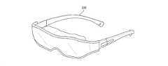
도 1은 헤드 마운티드 디스플레이의 일 예시를 도시한다.Figure 1 shows an example of a head-mounted display.
유저의 신체에 마운트되는 웨어러블(wearable) 디바이스가 이용되고 있다. 예를 들어, 도 1에 도시된 헤드 마운티드 디스플레이는 웨어러블 디바이스의 일 예시이다. 또한, 헤드 마운티드 디스플레이는, 도 1에 도시된 바와 같이, 안경과 유사한 형태를 가져 항시 착용이 가능하다.Wearable devices that are mounted on the user's body are used. For example, the head-mounted display shown in Fig. 1 is an example of a wearable device. In addition, the head-mounted display has a shape similar to that of glasses as shown in Fig. 1, and is always wearable.
헤드 마운티드 디스플레이는 유저가 현실의 세계의 리얼 오브젝트와 가상 현실 이미지를 함께 볼 수 있는 개방형 시야(open-view) 타입 또는 유저가 가상 현실 이미지만을 볼 수 있는 폐쇄형 시야(closed-view) 타입으로 구분될 수 있다. 개방형 시야를 갖는 헤드 마운티드 디스플레이는 증강 현실(AR: Argumented Reality) 또는 혼합 현실(MR: Mixed Reality)을 이용하여 유저에게 증가된 몰입감을 제공할 수 있다.The head-mounted display is divided into an open-view type in which a user can view a real object and a virtual reality image in the real world or a closed-view type in which a user can view only a virtual reality image. . A head-mounted display having an open field of view can provide an increased immersion feeling to a user by using AR (Argumented Reality) or mixed reality (MR).
도 2는 헤드 마운티드 디스플레이의 유저가 양손을 이용할 수 없는 상황을 도시한다.Fig. 2 shows a situation in which the user of the head-mounted display can not use both hands.
헤드 마운티드 디스플레이는 손에 의한 입력을 수신할 수 있다. 예를 들어, 유저는 헤드 마운티드 디스플레이의 지지부를 터치함으로써 헤드 마운티드 디스플레이를 제어할 수도 있다. 그러나, 도 2에 도시된 바와 같이, 유저가 양손을 이용할 수 없는 경우에는 헤드 마운티드 디스플레이에 대한 제어가 용이하지 않다. 또한, 유저는 단순히 양손을 사용하지 않고 헤드 마운티드 디스플레이를 제어하기를 원할 수도 있다. 이러한 문제점을 해결하기 위하여, 유저의 시선을 인식하여 헤드 마운티드 디스플레이를 제어하는 방법이 연구되고 있다. 그러나, 외부 오브젝트가 존재하는 상황에서, 유저는 시선을 한 점에 고정하는 것이 어렵다.The head-mounted display can receive input by hand. For example, the user may control the head-mounted display by touching the support of the head-mounted display. However, as shown in Fig. 2, it is not easy to control the head-mounted display when the user can not use both hands. In addition, the user may want to control the head-mounted display without simply using both hands. In order to solve such a problem, a method of controlling a head-mounted display by recognizing a user's gaze has been studied. However, in a situation where an external object exists, it is difficult for the user to fix the line of sight to one point.
본 명세서는, 헤드 마운티드 디스플레이 및 그 제어 방법을 제공하고자 한다. 특히, 유저의 발을 이용하여 헤드 마운티드 디스플레이를 제어함으로써 보다 개선된 유저 인터페이스를 제시하고자 한다.The present specification aims to provide a head-mounted display and a control method thereof. In particular, the present invention aims to provide a more improved user interface by controlling the head-mounted display using the user's feet.
본 명세서의 일 실시예에 따른 헤드 마운티드 디스플레이(HMD)는, 적어도 하나의 이미지를 디스플레이하는 디스플레이 유닛, HMD의 속력 및 움직임 중 적어도 하나를 측정하는 무브먼트 센싱 유닛, HMD의 틸트(tilt) 각도를 센싱하는 각도 센싱 유닛, HMD의 외부에 위치한 적어도 하나의 리얼 오브젝트를 센싱하는 이미지 센싱 유닛 및 디스플레이 유닛, 무브먼트 센싱 유닛, 각도 센싱 유닛 및 상기 이미지 센싱 유닛을 제어하는 프로세서를 포함하고, 프로세서는, 컨텐츠를 디스플레이 유닛 상에 디스플레이하고, 센싱된 적어도 하나의 리얼 오브젝트 중 하나의 리얼 오브젝트를 입력 수단으로 정의하고, HMD의 틸트 각도가 제1 각도 이하인 경우, 컨텐츠의 제어를 제공하는 제어 인터페이스를 디스플레이 유닛 상에 디스플레이하고, 기설정된 시간 이후에 제어 인터페이스의 디스플레이를 종료하며, HMD의 틸트 각도가 제2 각도를 초과하고, 무브먼트 센싱 유닛을 이용하여 HMD가 정지 상태로 판단된 경우, 제어 인터페이스를 지면(ground) 상에 매핑하고, 매핑된 제어 인터페이스를 디스플레이 유닛 상에 디스플레이하고, 제어 인터페이스는 입력 수단에 의한 입력에 기초하여 제어되고, 제1 각도는 제2 각도 이하일 수 있다.A head-mounted display (HMD) according to one embodiment of the present invention includes a display unit for displaying at least one image, a movement sensing unit for measuring at least one of the speed and the movement of the HMD, a tilt angle sensor for sensing the tilt angle of the HMD An image sensing unit and a display unit for sensing at least one real object located outside the HMD, a movement sensing unit, an angle sensing unit, and a processor for controlling the image sensing unit, A control interface for displaying control information on the display unit and defining a real object of at least one of the sensed real objects as input means and for controlling the content when the tilt angle of the HMD is equal to or less than a first angle, Display, and control after a preset time When the tilt angle of the HMD exceeds the second angle and the HMD is judged to be in the stopped state using the movement sensing unit, the control interface is mapped on the ground, and the mapped control The interface is displayed on the display unit, and the control interface is controlled based on the input by the input means, and the first angle may be equal to or less than the second angle.
그리고, 프로세서는, HMD의 틸트 각도가 제2 각도를 초과하고, HMD가 정지 상태로 판단된 경우, HMD의 유저의 발 및 신발 중 적어도 하나를 입력 수단으로 정의할 수 있다.The processor may define at least one of the foot and shoe of the user of the HMD as input means when the tilt angle of the HMD exceeds the second angle and the HMD is determined to be in the stopped state.
그리고, 프로세서는, HMD의 유저의 발 및 신발 중 적어도 하나가 입력 수단으로 정의된 경우, HMD의 유저의 손이 상기 이미지 센싱 유닛에 의하여 기설정된 시간 이상 센싱되면 입력 수단을 상기 유저의 손으로 전환할 수 있다.When at least one of the foot and shoe of the user of the HMD is defined as the input means, the processor switches the input means to the user's hand when the user's hand of the HMD is sensed by the image sensing unit for a predetermined time or more can do.
또한, 프로세서는, HMD의 유저의 양쪽 발 또는 양쪽 신발이 이미지 센싱 유닛에 의하여 센싱되는 경우, HMD의 유저의 양쪽 발 중 한쪽 발 또는 양쪽 신발 중 한쪽 신발을 입력 수단으로 정의할 수 있다.In addition, the processor may define one foot or both shoes of the user's feet of the HMD as input means when both feet or both shoes of the user of the HMD are sensed by the image sensing unit.
그리고, 프로세서는, 기설정된 선호값, HMD의 유저의 양쪽 다리 각각의 사용 빈도, 및 양쪽 발 또는 양쪽 신발의 움직임 중 적어도 하나에 기초하여 한쪽 발 또는 한쪽 신발을 입력 수단으로 정의할 수 있다.The processor may define one foot or one shoe as an input means based on at least one of a preset preference value, a frequency of use of each leg of the user of the HMD, and movement of both feet or both shoes.
그리고, 프로세서는, 입력 수단에 인접하게 상기 매핑된 제어 인터페이스를 디스플레이할 수 있다.And, the processor can display the mapped control interface adjacent to the input means.
그리고, 제어 인터페이스는 컨텐츠의 제어를 제공하는 복수의 이미지들을 포함하고, 프로세서는, 입력 수단으로 정의된 한쪽 발 또는 한쪽 신발의 방향에 기초하여 복수의 이미지들의 배열을 결정할 수 있다.And, the control interface includes a plurality of images providing control of the content, and the processor can determine the arrangement of the plurality of images based on the orientation of one foot or one shoe defined by the input means.
그리고, 제어 인터페이스는 컨텐츠의 제어를 제공하는 복수의 이미지들을 포함하고, 프로세서는, 유저의 신발이 입력 수단으로 정의된 경우, 신발의 종류에 기초하여 이미지, 이미지의 배열, 이미지의 크기 및 이미지의 수 중 적어도 하나를 결정할 수 있다.And, the control interface includes a plurality of images providing control of the content, and the processor, when the user's shoes are defined as the input means, displays the images, the arrangement of the images, the size of the images, At least one of the numbers can be determined.
그리고, 프로세서는, 센싱된 신발의 크기, 신발의 모양 및 신발의 색상 중 적어도 하나에 기초하여 신발의 종류를 결정할 수 있다.The processor may determine the type of shoe based on at least one of the size of the shoe, the shape of the shoe, and the color of the shoe.
또한, 프로세서는, 신발의 크기 및 신발 끝의 첨예도 중 적어도 하나에 기초하여 복수의 이미지들 각각의 크기를 조정할 수 있다.In addition, the processor may adjust the size of each of the plurality of images based on at least one of shoe size and shoe sharpness.
한편, 프로세서는, HMD의 유저의 발 및 신발 중 적어도 하나가 입력 수단으로 정의되면, 입력 수단을 제외한 외부 리얼 오브젝트에 의한 입력을 제한할 수 있다.On the other hand, if at least one of the foot and shoe of the user of the HMD is defined as the input means, the processor can restrict the input by the external real object excluding the input means.
한편, 입력 수단에 의한 입력은, 입력 수단의 제스쳐(gesture)에 기초하여 결정되고, 제스쳐는 입력 수단의 이동, 호버링(hovering), 홀딩(holding), 탭핑(tapping) 및 더블 탭핑 중 적어도 하나를 포함할 수 있다.On the other hand, the input by the input means is determined based on the gesture of the input means, and the gesture may include at least one of moving, hovering, holding, tapping and double tapping of the input means .
그리고, 제어 인터페이스는 컨텐츠의 제어를 제공하는 복수의 이미지들을 포함하고, 복수의 이미지들 중 적어도 하나의 이미지에 대한 입력은, 입력 수단의 기설정된 제스쳐에 의하여만 입력될 수 있다.And, the control interface includes a plurality of images providing control of the contents, and the input to at least one of the plurality of images can be input only by a predetermined gesture of the input means.
한편, 프로세서는, HMD의 틸트 각도가 제2 각도를 초과하고, HMD가 정지 상태로 판단된 경우, 이미지 센싱 유닛에 의하여 센싱된 지면의 상태에 기초하여 제어 인터페이스의 디스플레이 위치 및 크기 중 적어도 하나를 결정하고, 지면의 상태는 지면의 색상, 지면의 연속성, 지면의 높이차이, 지면의 평탄도, 지면의 기울기, 지면의 재질, 지면 상의 표식 및 지면 상의 외부 리얼 오브젝트 중 적어도 하나를 포함할 수 있다.On the other hand, the processor can determine at least one of the display position and the size of the control interface based on the state of the ground sensed by the image sensing unit when the tilt angle of the HMD exceeds the second angle and the HMD is determined to be stationary And the state of the paper surface may include at least one of the color of the paper surface, the continuity of the paper surface, the height difference of the paper surface, the flatness of the paper surface, the inclination of the paper surface, the material of the paper surface, the mark on the paper surface, .
그리고 프로세서는, 지면의 상태에 기초하여 장애물 및 안전 위험 중 적어도 하나를 디텍트하고, 디텍트된 장애물 및 안전 위험 중 적어도 하나를 회피하도록 제어 인터페이스의 디스플레이 위치 및 크기 중 적어도 하나를 결정할 수 있다.The processor may then determine at least one of the display position and the size of the control interface to detect at least one of the obstacle and the safety risk based on the state of the ground and to avoid at least one of the detected obstacle and the safety risk.
또한, 프로세서는, 입력 수단과 디텍트된 장애물 및 안전 위험 중 적어도 하나 사이의 거리가 기설정된 거리 이상이면 매핑된 제어 인터페이스를 디스플레이하고, 입력 수단과 상기 디텍트된 장애물 및 안전 위험 중 적어도 하나 사이의 거리가 기설정된 거리 미만이면 매핑된 제어 인터페이스를 디스플레이하지 않을 수 있다.The processor may also display a mapped control interface if the distance between the input means and at least one of the detected obstacles and safety hazards is greater than a predetermined distance and that the mapped control interface is present between the input means and at least one of the detected obstacles and safety hazards It may not display the mapped control interface.
또한, 프로세서는, 지면의 상태에 기초하여 계단을 디텍트하고, HMD의 유저가 서있는 계단의 다음 계단에 대응하는 디스플레이 유닛 상의 위치에 매핑된 제어 인터페이스를 디스플레이할 수 있다.The processor can also detect the stair based on the state of the ground and display the control interface mapped to the location on the display unit corresponding to the next step of the stair where the user of the HMD stands.
한편, 프로세서는, HMD의 틸트 각도가 제2 각도를 초과하고, HMD가 정지 상태로 판단된 경우, 디스플레이 유닛 상의 기설정된 위치 또는 컨텐츠에 인접한 위치에 매핑된 제어 인터페이스를 디스플레이할 수 있다.On the other hand, the processor can display a control interface mapped to a predetermined position on the display unit or a position adjacent to the content, when the tilt angle of the HMD exceeds the second angle and the HMD is judged to be in the stopped state.
한편, 프로세서는, 매핑된 제어 인터페이스가 디스플레이되고, 기설정된 시간 내에 HMD의 방향이 유지된 채로 HMD가 HMD의 전방 또는 후방으로 이동되면, HMD의 이동 거리에 기초하여 제어 인터페이스의 디스플레이 크기를 변경할 수 있다.On the other hand, the processor can change the display size of the control interface based on the moving distance of the HMD when the HMD is moved forward or backward of the HMD while the mapped control interface is displayed and the orientation of the HMD is maintained within a predetermined time have.
한편, 프로세서는, HMD의 속력이 기설정된 속력 이하인 경우 및 HMD의 움직임이 없는 경우 중 적어도 하나의 경우에 HMD를 정지 상태로 판단할 수 있다.On the other hand, the processor can determine the HMD to be in a stopped state in at least one of the case where the speed of the HMD is less than the predetermined speed and the case where there is no motion of the HMD.
또한, 본 명세서의 일 실시예에 따른 헤드 마운티드 디스플레이(HMD: Head Mounted Display)의 제어 방법은, 컨텐츠를 HMD의 디스플레이 유닛 상에 디스플레이하는 단계, HMD의 틸트(tilt) 각도를 센싱하는 단계 및 컨텐츠의 제어를 제공하는 제어 인터페이스를 제공하는 단계를 포함하고, 제어 인터페이스를 제공하는 단계는, 센싱된 틸트 각도가 제1 각도 이하인 경우, HMD의 외부에 위치한 하나 이상의 리얼 오브젝트 중 하나의 리얼 오브젝트를 제1 입력 수단으로 정의하고, 제어 인터페이스를 디스플레이 유닛 상에 디스플레이하고, 기설정된 시간 이후에 제어 인터페이스의 디스플레이를 종료하는 단계 및 센싱된 틸트 각도가 제2 각도를 초과하고, HMD의 속력 및 움직임 중 적어도 하나에 기초하여 HMD가 정지 상태로 판단된 경우, HMD의 외부에 위치한 하나 이상의 리얼 오브젝트 중 하나의 리얼 오브젝트를 제2 입력 수단으로 정의하고, 제어 인터페이스를 지면(ground) 상에 매핑하고, 매핑된 제어 인터페이스를 디스플레이 유닛 상에 디스플레이하는 단계를 포함하고, 제어 인터페이스는 제1 및 제2 입력 수단 중 적어도 하나에 의한 입력에 기초하여 제어되고, 제1 각도는 상기 제2 각도 이하일 수 있다.A method of controlling a head mounted display (HMD) according to an embodiment of the present invention includes displaying a content on a display unit of the HMD, sensing a tilt angle of the HMD, Wherein the step of providing the control interface comprises the step of providing one of the at least one real object located outside the HMD when the sensed tilt angle is equal to or less than the first angle, 1 input means, displaying the control interface on the display unit, terminating the display of the control interface after a predetermined time, and stopping the display of the control interface when the sensed tilt angle exceeds the second angle and at least one of the speed and the movement of the HMD If it is determined that the HMD is in a stopped state based on one, Defining a real object of one of the real objects as a second input means, mapping the control interface on the ground, and displaying the mapped control interface on a display unit, The first angle is controlled based on the input by at least one of the second input means, and the first angle may be equal to or less than the second angle.
본 명세서에 따르면, 헤드 마운티드 디스플레이는 보다 개선된 인터페이스를 제공할 수 있다.According to the present disclosure, a head-mounted display can provide a more advanced interface.
또한, 본 명세서에 따르면, 헤드 마운티드 디스플레이는 그 움직임을 센싱할 수 있다.Further, according to the present specification, a head-mounted display can sense its movement.
또한, 본 명세서에 따르면, 헤드 마운티드 디스플레이는 현실 세계의 리얼 오브젝트와 관련하여 제어 인터페이스를 제공할 수 있다.Further, according to the present specification, the head-mounted display can provide a control interface with respect to real-world real objects.
또한, 본 명세서에 따르면, 헤드 마운티드 디스플레이는 현실 세계의 안전 위험으로부터 보다 안전한 제어 인터페이스를 제공할 수 있다.In addition, according to the present disclosure, a head-mounted display can provide a more secure control interface from real-world safety hazards.
도 1은 HMD의 일 예시를 도시한다.
도 2는 HMD의 유저가 양손을 이용할 수 없는 상황을 도시한다.
도 3은 HMD의 구성도이다.
도 4는 HMD의 유저가 정면을 보는 경우를 도시한다.
도 5는 HMD의 유저가 지면을 보는 경우를 도시한다.
도 6은 HMD의 틸트(tilt) 각도를 도시한다.
도 7은 지면에 매핑된 제어 인터페이스의 예시들을 도시한다.
도 8은 신발에 기초한 제어 인터페이스의 예시들을 도시한다.
도 9는 일 실시예에 따른 HMD의 제어 인터페이스의 동작을 설명하기 위한 도면이다.
도 10은 또 다른 실시예에 따른 HMD의 제어 인터페이스의 동작을 설명하기 위한 도면이다.
도 11은 제스쳐의 예시들을 도시한다.
도 12는 특정 위치를 회피하도록 매핑되는 제어 인터페이스를 도시한다.
도 13은 계단에 매핑되는 제어 인터페이스를 도시한다.
도 14는 안전 위험에 기초한 제어 인터페이스를 도시한다.
도 15는 HMD의 이동에 따른 제어 인터페이스의 디스플레이 크기 변경을 도시한다.
도 16은 일 실시예에 따른 HMD의 제어 방법의 흐름도이다.
도 17은 일 실시예에 따른 HMD의 제어 방법의 흐름도이다.Figure 1 shows an example of an HMD.
Fig. 2 shows a situation in which a user of the HMD can not use both hands.
3 is a block diagram of the HMD.
4 shows a case where the user of the HMD looks straight ahead.
5 shows a case where the user of the HMD sees the ground.
Figure 6 shows the tilt angle of the HMD.
Figure 7 shows examples of control interfaces mapped to the ground.
Figure 8 shows examples of control interface based on shoes.
9 is a view for explaining the operation of the control interface of the HMD according to an embodiment.
10 is a diagram for explaining the operation of the control interface of the HMD according to another embodiment.
Figure 11 shows examples of gestures.
Figure 12 shows a control interface that is mapped to avoid certain locations.
Figure 13 shows a control interface mapped to a stair.
Figure 14 shows a control interface based on safety risk.
15 shows a display size change of the control interface as the HMD moves.
16 is a flowchart of a method of controlling an HMD according to an embodiment.
17 is a flowchart of a method of controlling an HMD according to an embodiment.
이하 상기의 목적을 구체적으로 실현할 수 있는 실시예를 첨부한 도면을 참조하여 상세히 설명한다. 이때 도면에 도시되고 또 이것에 의해서 설명되는 구성과 작용은 적어도 하나의 실시예로서 설명되는 것이며, 이것에 의해서 본 명세서의 기술적 사상과 그 핵심 구성 및 작용이 제한되지는 않는다.BRIEF DESCRIPTION OF THE DRAWINGS Fig. 1 is a perspective view showing a first embodiment of the present invention; Fig. The configuration and operation described in the drawings and described in the drawings are described as at least one embodiment, and the technical idea and the essential structure and operation of the present specification are not limited by the description.
본 명세서에서 사용되는 용어는 본 명세서에서의 기능을 고려하면서 가능한 현재 널리 사용되는 일반적 용어를 선택하였으나, 이는 당 분야에 종사하는 기술자의 의도 또는 관례 또는 새로운 기술의 출현 등에 따라 달라질 수 있다. 또한, 특정한 경우는 출원인이 임의로 선정한 용어도 있으며, 이 경우 해당되는 명세서의 설명 부분에서 그 의미를 기재할 것이다. 따라서 본 명세서에서 사용되는 용어는, 단순한 용어의 명칭이 아닌 그 용어가 가지는 실질적인 의미와 본 명세서의 전반에 걸친 내용을 토대로 해석되어야 함을 밝혀두고자 한다.As used herein, terms used in the present specification are selected from the general terms that are currently widely available while considering the functions in this specification, but these may vary depending on the intention or custom of the skilled person in the art or the emergence of new technologies. Also, in certain cases, there may be a term selected by the applicant at will, in which case the meaning will be described in the description part of the corresponding specification. Therefore, it is intended that the terminology used herein should be interpreted based on the meaning of the term rather than on the name of the term, and on the entire contents of the specification.
또한 본 명세서에 개시되어 있는 본 게시물의 개념에 따른 실시 예들에 대해서 특정한 구조적 내지 기능적 설명들은 단지 본 명세서의 개념에 따른 실시예를 설명하기 위한 목적으로 예시된 것으로, 본 명세서의 개념에 다른 실시 예들은 다양한 형태로 실시될 수 있으며 본 명세서에서 설명된 실시 예들에 한정되는 것으로 해석되어서는 아니 된다.It should also be noted that the specific structural and functional descriptions for embodiments in accordance with the concepts of the present disclosure set forth herein are illustrated for purposes of illustrating embodiments in accordance with the concepts of this disclosure, May be embodied in various forms and should not be construed as limited to the embodiments set forth herein.
본 명세서의 개념에 따른 실시 예는 다양한 변경을 가할 수 있고 여러 가지 형태를 가질 수 있으므로 특정 실시예들을 도면에 예시하고 본 명세서에 상세하게 설명하고자 한다. 그러나, 이는 본 명세서의 개념에 따른 실시 예를 특정한 개시 형태에 대해 한정하려는 것이 아니며, 본 명세서의 사상 및 기술 범위에 포함되는 모든 변경, 균등물 내지 대체물을 포함하는 것으로 이해되어야 한다.Embodiments in accordance with the concepts herein may be made in various manners and may take various forms, so that specific embodiments are illustrated in the drawings and described in detail herein. It is to be understood, however, that it is not intended to limit the embodiments consistent with the concepts herein to the particular forms disclosed, but includes all modifications, equivalents, and alternatives falling within the spirit and scope of the disclosure.
그리고 본 명세서에서 제1 및/또는 제2 등의 용어는 다양한 구성 요소들을 설명하는데 사용될 수 있지만, 상기 구성 요소들은 상기 용어들에 의해 한정되어서는 안 된다. 상기 용어들은 하나의 구성 요소를 다른 구성 요소로부터 구별하는 목적으로만, 예컨대 본 명세서의 개념에 따른 권리 범위로부터 이탈되지 않은 채, 제1 구성요소는 제2 구성요소로 명명될 수 있고, 유사하게, 제2 구성요소는 제1 구성요소로도 명명될 수 있다.And the terms first and / or second, etc., may be used herein to describe various components, but the components should not be limited by the terms. The terms may be named for the purpose of distinguishing one element from another, for example, without departing from the scope of the rights under the concept of the present disclosure, the first element being referred to as the second element, , The second component may also be referred to as a first component.
또한 명세서 전체에서, 어떤 부분이 어떤 구성 요소를 “포함”한다고 할 때, 이는 특별히 반대되는 기재가 없는 한 다른 구성 요소를 제외하는 것이 아니라 다른 구성 요소를 더 포함할 수 있는 것을 의미한다. 그리고 명세서에 기재된 “…유닛”, “…부” 등의 용어는 적어도 하나의 기능이나 동작을 처리하는 단위를 의미하며, 이는 하드웨어 및/또는 소프트웨어의 결합으로 구현될 수 있다.Also, throughout the specification, when an element is referred to as " including " an element, it means that the element may include other elements as well, without departing from the other elements unless specifically stated otherwise. And the description "... unit", "… Quot; and " part " refer to a unit for processing at least one function or operation, which may be implemented as a combination of hardware and / or software.
도 1은 HMD의 일 예시를 도시한다.Figure 1 shows an example of an HMD.
도 1에는 안경형의 HMD(100)가 도시되어 있다. 그러나, 본 개시물의 HMD(100)는 안경형의 HMD 뿐만 아니라, 헬멧형, 모자형, 고글형 및/또는 머리에 마운트될 수 있는 다양한 형태의 HMD를 포함할 수 있다. HMD(100)는 HMD(100)의 외부 오브젝트에 대한 시야를 차단하지 않으면서, 하나 이상의 컨텐츠를 디스플레이할 수 있다. HMD(100)는 유저에게 증강 현실(AR) 및/또는 혼합 현실(MR)을 제공할 수 있다.FIG. 1 shows an
도 3은 HMD의 구성도이다.3 is a block diagram of the HMD.
본 개시물의 HMD(100)는 적어도 하나의 이미지를 디스플레이하는 디스플레이 유닛(120), HMD(100)의 속력 및 움직임 중 적어도 하나를 측정하는 무브먼트 센싱 유닛(130), HMD(100)의 틸트(tilt) 각도를 센싱하는 각도 센싱 유닛(140), HMD(100)의 외부에 위치한 적어도 하나의 리얼 오브젝트를 센싱하는 이미지 센싱 유닛(150) 및 디스플레이 유닛(120), 무브먼트 센싱 유닛(130), 각도 센싱 유닛(140) 및 이미지 센싱 유닛(140)을 제어하는 프로세서(110)를 포함할 수 있다. 본 명세서에 개시된 HMD(100)의 동작들은 프로세서(110)에 의하여 수행될 수도 있다.The
또한, HMD(100)는 외부 디바이스와의 커뮤니케이션을 위한 커뮤니케이션 유닛(160) 및 전력원(170)을 더 포함할 수도 있다. 그러나, 이러한 구성들은 HMD(100)의 필수적 구성들은 아니다. 예를 들어, HMD(100)는 외부의 별도 전력원으로부터 전력을 공급받을 수도 있다. 또한, HMD(100)는 도 3에 도시된 구성 외의 임의의 다른 구성들을 더 포함하고 있을 수도 있다. 예를 들어, HMD(100)는 메모리를 더 포함할 수도 있다. 아울러, HMD(100)의 각 구성들은 버스(180)를 통하여 서로 연결될 수도 있다.In addition, the
디스플레이 유닛(120)은 렌즈, 투영면, 프로젝터 및/또는 프리즘을 포함할 수도 있다. 또한, 디스플레이 유닛(120)은 임의의 투명 디스플레이 유닛을 포함할 수도 있다. 디스플레이 유닛(120)의 HMD(100) 외부의 이미지를 실시간으로 디스플레이할 수도 있다.
무브먼트 센싱 유닛(130)은 가속도계, 속도계, 위성 위치확인 시스템, 자이로(gyro) 센서, 자기장 센서 및/또는 근접 센서를 포함할 수도 있다. 또한, 무브먼트 센싱 유닛(130)은 상술한 이미지 센싱 유닛(150)을 이용하여 HMD(100)의 속력 및 움직임 중 적어도 하나를 측정할 수도 있다.The
각도 센싱 유닛(140)은 가속도계, 자이로 센서 및/또는 중력 가속도계를 포함할 수도 있다. 각도 센싱 유닛(140)은 HMD(100)의 틸트 각도를 센싱할 수 있다. 틸트 각도는 HMD(100)의 유저가 정면을 바라볼 때를 기준으로 하여 HMD(100)의 틸트 각도를 센싱할 수 있다. 따라서, 유저가 정면을 바라볼 때 보다, 유저가 지면을 바라볼 때 틸트 각도가 더 클 수 있다. 그러나, HMD(100)의 틸트 각도는 중력 방향을 기준으로 센싱될 수도 있다. 이 경우, 유저가 지면을 바라볼 때 보다, 유저가 정면을 볼 때 HMD(100)의 틸트 각도가 더 클 수 있다. 이와 같이, HMD(100)의 틸트 각도는 다양한 기준에 따라서 측정될 수 있다. 이하에서는, 이해를 돕기 위하여, 틸트 각도는 유저가 정면을 바라볼 때를 기준으로 하여 센싱되는 것으로 정의한다. 그러나, 통상의 기술자는 다양한 기준에 기초하여 틸트 각도가 센싱될 수 있음을 이해할 수 있으며, 이는 본 개시물의 범위를 벗어나는 것이 아니다.The
이미지 센싱 유닛(150)은 HMD(100)의 외부에 존재하는 리얼 오브젝트를 센싱할 수 있다. 즉, 이미지 센싱 유닛(150)은 HMD(100)의 유저가 바라보는 방향에 존재하는 리얼 오브젝트를 센싱할 수 있다. 이미지 센싱 유닛(150)은 가시 광선, 적외선, 자외선, 자기장 및/또는 음파를 이용하여 이미지를 센싱할 수 있다.The
이상에서는, 도 1 및 도 3을 참조하여 HMD(100)의 구성이 설명되었다. 이하에서는, 본 개시물의 HMD(100)의 동작이 설명된다. 후술하는 HMD(100)의 동작은 상술한 HMD(100)의 구성(예를 들어, 프로세서(110))에 의하여 실시될 수 있다.In the above, the configuration of the
도 4는 HMD의 유저가 정면을 보는 경우를 도시한다.4 shows a case where the user of the HMD looks straight ahead.
도 4에서, HMD(100)의 유저는 정면을 보면서 걷고 있다. HMD(100)의 디스플레이 유닛 상에는 컨텐츠(210)가 디스플레이된다. 컨텐츠(210)는 정지 영상 및 동영상 중 적어도 하나를 포함할 수 있다. 유저는 HMD(100)를 조작하여 컨텐츠(210)의 디스플레이를 시작할 수 있다. 컨텐츠(210)의 디스플레이가 시작되면, 컨텐츠(210)의 제어를 제공하는 제어 인터페이스(220)가 HMD(100)의 디스플레이 유닛 상에 디스플레이된다. HMD(100)는 HMD(100)의 틸트 각도를 측정함으로써 HMD(100)의 유저가 정면을 보고 있음을 판단할 수도 있다.4, the user of the
또한, HMD(100)는 HMD(100)의 외부에 위치한 적어도 하나의 리얼 오브젝트를 이미지 센싱 유닛을 이용하여 센싱할 수 있다. HMD(100)는, 센싱된 적어도 하나의 리얼 오브젝트 중 하나의 리얼 오브젝트를 입력 수단으로 정의할 수 있다. 예를 들어, 도 4와 같이 HMD(100)의 유저가 정면을 보고 있는 경우에는, HMD(100)의 유저의 손이 입력 수단으로 정의될 수도 있다. HMD(100)는 이미지 센싱 유닛에 의하여 센싱되는 HMD(100)의 유저의 손의 형상을 인식함으로써 HMD(100)의 유저의 손을 입력 수단으로 정의할 수도 있다.In addition, the
한편, 제어 인터페이스(220)는 입력 수단에 의한 입력에 기초하여 제어된다. 제어 인터페이스(220)는 컨텐츠(210)의 제어를 제공하는 복수의 이미지들을 포함할 수도 있다. 예를 들어, 제어 인터페이스(220)는, 컨텐츠(210)의 재생, 되감기, 빨리감기, 정지 및 처음부터 재생 등의 제어를 제공하는 이미지들을 포함할 수도 있다. 따라서, 유저는 입력 수단이 자신의 손으로 정의되면, 예를 들어, 손을 해당 이미지를 향하여 뻗음으로서, 원하는 제어를 선택할 수 있다. 또한, 유저는 HMD(100)에 위치한 다른 입력 수단(예를 들어, HMD(100)의 지지대에 위치한 버튼 또는 터치 패드)을 조작함으로써 제어 인터페이스(220)를 제어할 수도 있다. 또한, 제어 인터페이스(220)는 디밍(dimming)될 수 있다. 즉, HMD(100)는 기설정된 시간 이후에 제어 인터페이스(220)의 디스플레이를 종료할 수 있다. 또한, HMD(100)는 유저로부터의 입력이 수신되면 제어 인터페이스(220)의 디스플레이를 유지할 수도 있다.On the other hand, the
그러나, 도 4에 도시된 바와 같이, HMD(100)의 유저는 양손이 가득찬 상황으로서, HMD(100)의 유저는 손으로 컨텐츠(210)를 제어하기가 매우 어렵다.However, as shown in FIG. 4, the user of the
도 5는 HMD의 유저가 지면을 보는 경우를 도시한다.5 shows a case where the user of the HMD sees the ground.
도 5에서, HMD(100)의 디스플레이 유닛 상에는 컨텐츠(210)가 디스플레이 되고, HMD(100)의 유저는 멈춰서 지면을 보고 있다. HMD(100)는 HMD(100)의 틸트 각도를 측정함으로써 HMD(100)의 유저가 지면을 보고 있음을 판단할 수 있다. 또한, HMD(100)는 HMD(100)의 무브먼트를 센싱함으로써 HMD(100)가 정지상태인지 판단할 수 있다. 예를 들어, HMD(100)는 HMD(100)의 속도, HMD(100)의 가속도, HMD(100)의 움직임 및/또는 HMD(100) 외부의 이미지를 이용하여 HMD(100)의 무브먼트를 센싱할 수도 있다. 또한, HMD(100)는 HMD(100)의 속력이 기설정된 속력 이하인 경우에 정지상태로 판단될 수 있다. 또한, HMD(100)는 HMD(100)의 움직임이 없는 경우에 정지상태로 판단될 수도 있다.5, the
HMD(100)의 유저가 지면을 바라보고, HMD(100)가 정지상태로 판단되면, HMD(100)는 제어 인터페이스(220)를 지면 상에 매핑하고, 매핑된 제어 인터페이스(220)를 디스플레이 유닛 상에 디스플레이한다. 제어 인터페이스(220)를 지면 상에 매핑함으로써, 제어 인터페이스(220)는 유저에게 지면 상에 그려진 것과 같이 디스플레이된다. HMD(100)는 컨텐츠(210)에 인접하게 제어 인터페이스(220)를 디스플레이할 수도 있다. 또한, HMD(100)는 디스플레이 유닛 상의 기설정된 위치에 제어 인터페이스(220)를 디스플레이할 수도 있다. 또한, 후술하는 바와 같이, HMD(100)는 입력 수단에 인접하게 제어 인터페이스(220)를 디스플레이할 수도 있다.When the user of the
또한, HMD(100)는 HMD(100)의 외부에 위치한 적어도 하나의 리얼 오브젝트를 이미지 센싱 유닛을 이용하여 센싱할 수 있다. HMD(100)는, 센싱된 적어도 하나의 리얼 오브젝트 중 하나의 리얼 오브젝트를 입력 수단으로 정의할 수 있다. 예를 들어, 도 5와 같이 HMD(100)의 유저가 지면을 보고 있는 경우에는, HMD(100)의 유저의 신발이 입력 수단으로 정의될 수도 있다. HMD(100)는 이미지 센싱 유닛에 의하여 센싱되는 HMD(100)의 유저의 신발의 형상을 인식함으로써 HMD(100)의 유저의 신발을 입력 수단으로 정의할 수도 있다. 또한, HMD(100)는 HMD(100)의 유저의 발, 목발, 유저의 손에 들린 막대기, 지팡이 또는 유저가 들고 있는 임의의 도구 를 입력 수단으로 정의할 수도 있다.In addition, the
한편, 제어 인터페이스(220)는 입력 수단에 의한 입력에 기초하여 제어된다. 제어 인터페이스(220)는 컨텐츠(210)의 제어를 제공하는 복수의 이미지들을 포함할 수도 있다. 예를 들어, 제어 인터페이스(220)는, 컨텐츠(210)의 재생, 되감기, 빨리감기, 정지 및 처음부터 재생 등의 제어를 제공하는 이미지들을 포함할 수도 있다. 따라서, 유저는 입력 수단이 신발으로 정의되면, 예를 들어, 신발을 해당 이미지를 향하여 뻗음으로서, 원하는 제어를 선택할 수 있다. 또한, 유저는 HMD(100)에 위치한 다른 입력 수단(예를 들어, HMD(100)의 지지대에 위치한 버튼 또는 터치 패드)을 조작함으로써 제어 인터페이스(220)를 제어할 수도 있다. 제어 인터페이스(220)는 HMD(100)가 이동함에 따라서 디밍될 수도 있다. 그러나, HMD(100)가 이동한다고 하더라도, HMD(100)는 제어 인터페이스(220)를 계속하여 디스플레이할 수도 있다. 예를 들어, HMD(100)는, 일단 제어 인터페이스가 지면에 매핑되어 디스플레이되었다면, 유저가 지면을 보면서 이동하는 동안 계속하여 제어 인터페이스(220)를 디스플레이할 수도 있다.On the other hand, the
도 6은 HMD의 틸트(tilt) 각도를 도시한다.Figure 6 shows the tilt angle of the HMD.
도 3과 관련하여 상술한 바와 같이, HMD(100)는 HMD(100)의 틸트 각도를 센싱할 수 있다. HMD(100)는 틸트 기설정된 틸트 각도의 범위를 이용하여 유저가 정면을 응시하는지 아니면 지면을 응시하는지를 판단할 수 있다. 예를 들어, 도 6에 도시된 바와 같이, 틸트 각도의 범위에 따라서, 유저의 시선 방향을 판단할 수 있다. 예를 들어, 기설정된 제1 틸트 각도 이하이면, HMD(100)는 유저가 정면을 응시하는 것으로 판단할 수 있다. 또한, 기설정된 제2 틸트 각도를 초과하면, HMD(100)는 유저가 지면을 응시하는 것으로 판단할 수 있다. 이 경우, 제1 틸트 각도는 제2 틸트 각도 이하일 수 있다.As described above with reference to FIG. 3, the
예를 들어, HMD(100)의 전방을 향하는 축이 지오이드(geoid) 면과 수평일 때, HMD(100)의 틸트 각도가 0도로 정의될 수도 있다. 또한, 유저가 고개를 숙임에 따라서, 틸트 각도가 증가되는 것으로 정의될 수도 있다. 예를 들어, HMD(100)의 전방을 향하는 축이 지면을 향하고, 지오이드 면과 수직일 때, HMD(100)의 틸트 각도가 90도로 정의될 수도 있다. 또한, HMD(100)의 전방을 향하는 축이 상공을 향하고, 지오이드 면과 수직일 때, HMD(100)의 틸트 각도가 -90도로 정의될 수도 있다. 따라서, HMD(100)의 전방향을 향하는 축이 지면을 향함에 따라서 틸트 각도가 증가할 수 있다. 이 경우, 틸트 각도가 일정 각도 이하이면, HMD(100)는 유저가 정면을 응시하는 것으로 판단할 수 있다. 예를 들어, HMD(100)는 틸트 각도가 45도 이하이면 유저가 정면을 응시하는 것으로 판단할 수도 있다. 또한, 틸트 각도가 일정 각도를 초과하면, HMD(100)는 유저가 지면을 응시하는 것으로 판단할 수도 있다. 예를 들어, HMD(100)는 틸트 각도가 45도를 초과하면 유저가 지면을 응시하는 것으로 판단할 수도 있다. 여기서, 45도는 임의의 다른 값으로 변경될 수도 있다.For example, when the axis toward the front of the
또한, 상술한 바와 같이, 틸트 각도는 중력방향을 기준으로 정의될 수도 있다. 이 경우, HMD(100)의 전방을 향하는 축이 지면을 향하고, 지오이드 면과 수직일 때, HMD(100)의 틸트 각도가 0도로 정의될 수도 있다. 또한, HMD(100)의 전방을 향하는 축이 상공을 향하면 틸트 각도가 증가하는 것으로 정의될 수도 있다. 이 경우, HMD(100)는 틸트 각도가 일정 각도를 초과하면 사용자가 정면을 응시하는 것으로 판단할 수도 있다.Further, as described above, the tilt angle may be defined with reference to the gravitational direction. In this case, the tilt angle of the
상술한 바와 같이, 틸트 각도는 그 기준에 따라서 달라질 수 있다. 다만, 이하에서는 설명의 편의를 위하여, HMD(100)가 전방을 향하는 축이 지면을 향할수록 틸트 각도가 증가하는 것을 기준으로 설명한다.As described above, the tilt angle can be changed according to the reference. Hereinafter, for the sake of convenience of explanation, the tilt angle increases as the axis of the
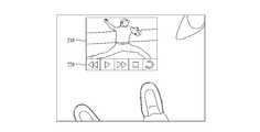
도 7은 지면에 매핑된 제어 인터페이스의 예시들을 도시한다.Figure 7 shows examples of control interfaces mapped to the ground.
HMD(100)는 유저의 신발 또는 발을 입력 수단으로 정의할 수 있다. 또한, HMD(100)는 유저의 양쪽 발 또는 신발이 이미지 센싱 유닛에 의하여 센싱되는 경우, HMD(100)의 유저의 양쪽 발 중 한쪽 발 또는 양쪽 신발 중 한쪽 신발을 입력 수단으로 정의할 수 있다. 예를 들어, HMD(100)는 기설정된 선호값, HMD(100)의 유저의 양쪽 다리 각각의 사용 빈도 및 양쪽 발 또는 양쪽 움직임 중 적어도 하나에 기초하여 한쪽 발 또는 한쪽 신발을 입력 수단으로 정의할 수 있다. 예를 들어, 제어 인터페이스(220)의 제어를 위하여 더 자주 사용되는 발(또는 신발) 또는 제어 인터페이스(220)가 디스플레이되기 직전에 움직임이 있는 발(또는 신발)이 입력 수단으로 정의될 수도 있다. 예를 들어, 양쪽 중 더 앞쪽으로 나와있는 쪽이 입력 수단으로 정의될 수도 있다.The
도 7에서, HMD(100)의 디스플레이 유닛 상에 컨테츠(210) 및 제어 인터페이스(220)가 디스플레이된다. 제어 인터페이스(220)는 지면에 매핑되어 디스플레이 된다. 도 7에서, HMD(100)는 제어 인터페이스(220)를 신발의 위치와 관련하여 디스플레이한다. 도 7에서 입력 수단은 HMD(100)의 유저의 오른쪽 신발이나, 도 5와 관련하여 상술한 바와 같이, 다양한 외부 리얼 오브젝트가 입력 수단으로 정의될 수 있으며, HMD(100)의 유저의 왼쪽 신발이 입력 수단으로 정의될 수도 있다.In Fig. 7, the
도 7의 (a)는 제어 인터페이스(220)의 일 실시예이다. 제어 인터페이스(220)는 컨텐츠(210)의 제어를 제공하는 복수의 이미지들을 포함하고 있다.FIG. 7A is an embodiment of the
HMD(100)는 입력 수단으로 정의된 한쪽 발 또는 한쪽 신발의 방향에 기초하여 제어 인터페이스 내의 이미지들의 배열을 결정할 수 있다. 도 7의 (b)에서, HMD(100)는 유저의 오른쪽 신발과 관련하여 복수의 이미지들을 정렬한다. 예를 들어 도 7의 (b)에 도시된 바와 같이, 재생 이미지가 오른쪽 신발에 가깝도록 복수의 이미지들이 정렬될 수도 있다.The
또한, HMD(100)는 입력 수단으로 정의된 한쪽 발 또는 한쪽 신발에 인접하게 제어 인터페이스(220)를 디스플레이할 수도 있다. 도 7의 (c)에서, HMD(100)는 유저의 오른쪽 신발에 인접하게 제어 인터페이스(220)를 디스플레이한다. 또한, 도 7의 (d)에 도시된 바와 같이, HMD(100)는 제어 인터페이스(220)를 입력 수단에 인접한 반원형으로 디스플레이할 수도 있다. 이 경우, 제어 인터페이스(220)의 복수의 이미지 모두가 입력 수단과 인접하게 디스플레이된다.In addition, the
도 8은 신발에 기초한 제어 인터페이스의 예시들을 도시한다.Figure 8 shows examples of control interface based on shoes.
상술한 바와 같이, 제어 인터페이스(220)는 컨텐츠(210)의 제어를 제공하는 복수의 이미지들을 포함할 수 있다. 또한, HMD(100)는 유저의 신발이 입력 수단으로 정의된 경우, 신발의 종류에 기초하여 이미지 자체, 이미지의 배열, 이미지의 크기 및 이미지의 수 중 적어도 하나를 결정할 수 있다. 또한, HMD(100)는 신발의 크기, 신발의 모양 및 신발의 색상 중 적어도 하나에 기초하여 신발의 종류를 결정할 수 있다. 따라서, 제어 인터페이스(220)는 입력 수단으로 정의된 신발의 종류에 따라서 개성화될 수도 있다.As described above, the
도 8의 (a)에서, HMD(100)는 유저의 신발을 남성용 구두로 판단하고, 남성용 구두에 대응하는 제어 인터페이스(220)를 디스플레이할 수 있다.8 (a), the
또한, 도 8의 (b)에서, 하이힐이 입력 수단으로서 정의된다. 도 8의 (b)에서, 제어 인터페이스(220)는 도 8의 (a)보다 많은 이미지들을 포함하고 있다. 또한, 각 이미지의 크기가 도 8의 (a)의 각 이미지보다 작다. 즉, HMD(100)는 신발의 종류에 대응하여 이미지의 수를 결정할 수 있다. 또한, HMD(100)는 신발의 크기 및 신발 끝의 첨예도 중 적어도 하나에 기초하여 제어 인터페이스(220)의 이미지들의 크기를 조정할 수도 있다.8 (b), the high heel is defined as the input means. In Figure 8 (b), the
한편, 도 8의 (b)의 우측에는 선택 가이드(230)가 도시된다. 선택 가이드(230)는, 예를 들어, 유저로 하여금 현재 입력 수단으로서 정의된 신발의 종류를 선택할 수 있도록 한다. 따라서, 유저는 선택 가이드(230)를 이용하여 신발의 종류를 선택함으로써 각 신발에 따라 개성화된 제어 인터페이스(220)를 선택할 수 있다.On the other hand, a
도 8의 (c)에서, 운동화가 입력 수단으로서 정의된다. HMD(100)는 운동화에 대응하는 이미지들을 포함하는 제어 인터페이(220)를 디스플레이할 수도 있다. 즉, HMD(100)는 유저의 신발의 종류에 기초하여 제어 인터페이스(220) 내의 이미지 자체를 결정할 수도 있다.8 (c), a sneaker is defined as an input means. The
도 8의 (d)에서, 슬리퍼가 입력 수단으로서 정의된다. 예를 들어, 슬리퍼는 끝이 둥글고 움직임이 편치 않기 때문에, HMD(100)는 보다 적은 수의 이미지들을 갖는 제어 인터페이스(220)를 디스플레이할 수도 있다. 또한, 보다 적은 움직임으로 이미지를 선택할 수 있도록, 제어 인터페이스(220)는 슬리퍼에 인접한 원형으로 디스플레이될 수도 있다.8 (d), a slipper is defined as an input means. For example, since the slipper has a rounded end and is not comfortable to move, the
또한, HMD(100)는 신발(예를 들어, 슬리퍼)을 마커로써 이용할 수도 있다. HMD(100)는 신발에 인접하게 제어 인터페이스(220)를 디스플레이할 수 있다. 유저는 신발을 벗고 발로 제어 인터페이스(220)에 대한 입력을 수행할 수도 있다. 이 경우, HMD(100)는 마커(신발) 주변에 제어 인터페이스(220)를 디스플레이하고, 유저의 발을 입력 수단으로서 정의할 수도 있다.Further, the
도 9는 일 실시예에 따른 HMD의 제어 인터페이스의 동작을 설명하기 위한 도면이다.9 is a view for explaining the operation of the control interface of the HMD according to an embodiment.
도 9에서, 유저의 신발이 입력 수단으로서 정의된다. 이 경우, 다른 행인의 발 또는 신발이 HMD(100)에 의하여 센싱될 수도 있다. 다른 행인에 의한 입력을 방지하기 위하여, HMD(100)는 일단 유저의 발 및 신발 중 적어도 하나가 입력 수단으로 정의되면, 입력 수단을 제외한 외부 리얼 오브젝트에 의한 입력을 제한할 수 있다.In Fig. 9, the user's shoes are defined as input means. In this case, the feet or shoes of another passenger may be sensed by the
도 10은 또 다른 실시예에 따른 HMD의 제어 인터페이스의 동작을 설명하기 위한 도면이다.10 is a diagram for explaining the operation of the control interface of the HMD according to another embodiment.
도 5 및 도 9와 관련하여 상술한 바와 같이, HMD(100)는 유저의 발 또는 신발을 입력 수단으로 정의할 수 있고, 입력 수단을 제외한 외부 리얼 오브젝트에 의한 입력을 제한할 수 있다. 그러나, 도 10에 도시된 바와 같이, HMD(100)의 유저는 다시 손을 이용하여 제어 인터페이스(220)를 제어하기를 원할 수도 있다. HMD(100)는 유저의 손이 기설정된 시간 이상 이미지 센싱 유닛에 의하여 센싱되면 입력 수단을 유저의 손으로 전환할 수 있다. 또한, 유저의 손에 의한 다른 입력(예를 들어, HMD(100)에 위치하는 버튼 또는 터치 패드를 통한 입력)이 수신되면, HMD(100)는 유저의 손을 입력 수단으로 전환할 수도 있다.As described above with reference to Figs. 5 and 9, the
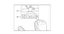
도 11은 제스쳐의 예시들을 도시한다.Figure 11 shows examples of gestures.
HMD(100)는 입력 수단에 의한 입력에 기초하여 제어될 수 있다. 또한, 입력 수단에 의한 입력은 입력 수단의 제스쳐(gesture)에 기초하여 결정될 수 있다. 예를 들어, 제스쳐는 입력 수단의 이동, 호버링(hovering), 홀딩(holding), 탭핑(tapping) 및 더블 탭핑 중 적어도 하나를 포함할 수 있다. HMD(100)는 이미지 센싱 유닛을 이용하여 입력 수단의 제스쳐를 센싱할 수도 있다.The
도 11에서, 복수의 이미지를 포함하고, 지면에 매핑된 제어 인터페이스(220)가 디스플레이된다. 유저는 자신의 발 또는 신발이 입력 수단으로 정의된 후, 원하는 이미지에 대한 제스쳐를 수행함으로써 컨텐츠(210)를 제어할 수 있다. 예를 들어, 유저는 디스플레이된 이미지 위에 발을 호버링 함으로써 해당 이미지에 대응하는 제어를 수행할 수 있다. 그러나, 오입력을 방지하기 위하여, 이미지에 대한 입력은 기설정된 제스쳐에 의하여만 입력될 수도 있다. 또한, HMD(100)에 대한 몇몇 제어는 HMD(100)에 대한 물리적 입력에 의하여만 입력되도록 제한될 수도 있다. 한편, 제한된 제어에 대한 제스쳐에 의한 입력이 시도되면, 해당 제어는 기설정된 입력(예를 들어, 물리적 입력)을 요구함을 나타내는 가이드가 제공될 수도 있다.In Fig. 11, a
도 11의 (a)에서, 유저는 제어 인터페이스(220)의 멈춤 이미지를 탭핑한다. 이처럼, 멈춤 이미지에 대한 입력은 탭핑에 의하여만 입력될 수도 있다. 또한, 멈춤/재생에 대한 입력은 유저의 더블 탭핑에 의하여만 입력될 수 있도록 제한될 수도 있다. 아울러, HMD(100)는 탭핑 후 유저가 일정시간 이상 발을 해당 위치에 홀딩할 때에만 입력으로 인정할 수도 있다.In Figure 11 (a), the user taps the pause image of the
도 11의 (b)에서, 유저는 빨리감기 이미지 상에서 입력 수단(신발)을 호버링한다. HMD(100)는 호버링이 유지되는 동안 계속하여 컨텐츠(210)의 빨리감기를 수행할 수 있다.In Fig. 11 (b), the user hoveres the input means (shoe) on the fast forward image. The
도 11의 제스쳐는 예시적인 것이며, 다양한 입력 수단의 제스쳐가 이용될 수도 있다. 또한, 컨텐츠(210)에 대한 제어의 유형에 따라서, 서로 다른 제스쳐가 이용될 수도 있다. 예를 들어, 멈춤/재생은 다른 제어보다 더 복잡한 제스쳐가 요구될 수도 있다.The gesture of Fig. 11 is exemplary and a gesture of various input means may be used. Also, different gestures may be used, depending on the type of control on
도 12는 특정 위치를 회피하도록 매핑되는 제어 인터페이스를 도시한다.Figure 12 shows a control interface that is mapped to avoid certain locations.
HMD(100)는, 지면에 매핑된 제어 인터페이스(220)를 디스플레이할 때, 이미지 센싱 유닛에 의하여 센싱된 지면의 상태에 기초하여 제어 인터페이스의 디스플레이 위치 및 크기 중 적어도 하나를 결정할 수 있다. 또한, 지면의 상태는 지면의 색상, 지면의 연속성, 지면의 높이차이, 지면의 평탄도, 지면의 기울기, 지면의 재질, 지면 상의 표식 및 지면 상의 외부 리얼 오브젝트 중 적어도 하나를 포함할 수 있다. HMD(100)는, 예를 들어, 지면의 깊이(depth), 지면의 색상 등을 측정함으로서 지면의 상태를 센싱할 수도 있다.The
도 12에서, 지면 상에 물 웅덩이가 존재한다. 이 경우, HMD(100)는 물 웅덩이를 회피하여 제어 인터페이스(220)를 디스플레이한다. 도 12는 회피 디스플레이의 예시로서, HMD(100)는 센싱된 지면 상태에 기초하여 장애물 및 안전 위험 중 적어도 하나를 디텍트할 수 있다. 예를 들어, 도 12의 물 웅덩이는 장애물 및/또는 안전 위험으로 분류될 수도 있다. 또한, HMD(100)는 디텍트된 장애물 및/또는 안전 위험을 회피하도록 제어 인터페이스(220)의 디스플레이 위치 및 크기 중 적어도 하나를 결정할 수 있다.In Fig. 12, there is a water sump on the ground. In this case, the
예를 들어, 지면의 급격한 기울기 변화가 있는 지점은 장애물로서 디텍트될 수도 있다. 따라서, HMD(100)는 장애물로 디텍트된 위치를 회피하여 제어 인터페이스(220)를 디스플레이할 수 있다. 또한, HMD(100)는 지면 상에 돌출된 외부 리얼 오브젝트(예를 들어, 지면 상의 다른 사람의 발, 지면 상의 돌출된 블록 등)를 장애물로서 디텍트할 수도 있다.For example, points with sudden gradient changes in the ground may be detected as obstacles. Accordingly, the
예를 들어, HMD(100)는, 차도, 횡단 보도, 지면 상의 뽀족한 물체, 지면 상의 얼음, 지면 상의 물 웅덩이, 지면 상의 구멍 등을 안점 위험으로서 디텍트할 수도 있다.For example, the
도 13은 계단에 매핑되는 제어 인터페이스를 도시한다.Figure 13 shows a control interface mapped to a stair.
도 13에서, 유저는 계단을 이동하다가 바닥을 보고 정지한 상태이다. 이 경우, HMD(100)는 지면의 상태에 기초하여 계단을 디텍트할 수 있다. 예를 들어, HMD(100)는 지면의 불연속성, 또는 지면의 깊이에 기초하여 계단을 디텍트할 수도 있다. 또한, HMD(100)는 유저가 서있는 계단의 다음 계단에 대응하는 디스플레이 유닛 상의 위치에 지면에 매핑된 제어 인터페이스(220)를 디스플레이할 수도 있다.In Fig. 13, the user is in a state of stopping at the bottom while moving the stairs. In this case, the
한편, 도 13에 도시된 바와 같이, 유저의 손이 입력 수단으로서 전환될 수도 있다. 이는, 도 10과 관련하여 상술한 바와 같다. 또한, 예를 들어, 경사가 높은 지면에 제어 인터페이스(220)가 매핑되고 디스플레이될 수도 있다. 이 경우, 유저의 손에 의한 입력이 용이할 수도 있다. 따라서, HMD(100)는 유저의 손 또는 유저가 손에 들고 있는 오브젝트로 입력 수단을 전환할 수도 있다. 또한, 제어 인터페이스(220)는, 유저의 이동이 시작되더라도, 일단 디스플레이 되었으면 계속하여 디스플레이 될 수도 있다. 이 경우, HMD(100)는 HMD(100)가 정지상태라고 판단될 경우에만 입력을 수신할 수도 있다. 또한, HMD(100)는 입력 수단이 발 또는 신발로부터 다른 입력 수단(예를 들어, 유저의 손)으로 전환될 때에만 입력을 수신할 수도 있다.On the other hand, as shown in Fig. 13, the hand of the user may be switched as an input means. This is as described above with reference to FIG. Also, for example, the
도 14는 안전 위험에 기초한 제어 인터페이스를 도시한다.Figure 14 shows a control interface based on safety risk.
도 13과 관련하여 상술한 바와 같이, HMD(100)는 장애물 및 안전 위험 중 적어도 하나를 디텍트할 수 있다. 또한, HMD(100)는 입력 수단과 디텍트된 장애물 및 안전 위험 중 적어도 하나 사이의 거리가 기설정된 거리 이상이면 지면에 매핑된 제어 인터페이스를 디스플레이할 수도 있다. 또한, HMD(100)는 입력 수단과 디텍트된 장애물 및 안전 위험 중 적어도 하나 사이의 거리가 기설정된 거리 미만이면 지면에 매핑된 제어 인터페이스를 디스플레이하지 않을 수도 있다.As described above in connection with FIG. 13, the
도 14에서, 유저는 횡단보도를 건너기 위하여 인도에 서있다.In Fig. 14, the user stands in India to cross the crosswalk.
도 14의 (a)에서, 제어 인터페이스(220)가 디스플레이되면, 유저는 제어 인터페이스(220)에 대한 입력을 수행하기 위하여 차도에 발을 뻗어야 하는 위험이 있다. HMD(100)는 지면의 색상, 지면의 높이차이 및 지면 상의 표식(예를 들어, 횡단 보도 표시 또는 차선 표시) 중 적어도 하나에 기초하여 안전 위험(예를 들어, 횡단 보도 또는 차도)을 디텍트할 수 있다. 도 14의 (a)에서, 입력 수단(유저의 발)과 차도의 거리가 지나치게 가깝기 때문에 HMD(100)는 제어 인터페이스(220)를 디스플레이하지 않을 수 있다.In Figure 14 (a), when the
도 14의 (b)에서, 유저는 차도로부터 한발짝 뒤로 물러선다. 이 경우, 안전 위험(예를 들어, 횡단 보도 또는 차도)으로부터 충분한 거리가 확보되었기 때문에, HMD(100)는 제어 인터페이스(220)를 디스플레이할 수도 있다.In (b) of FIG. 14, the user steps back from the driveway one step backward. In this case, the
도 15는 HMD의 이동에 따른 제어 인터페이스의 디스플레이 크기 변경을 도시한다.15 shows a display size change of the control interface as the HMD moves.
도 15의 (a)에서, 유저의 발이 입력수단으로 정의되고, 제어 인터페이스(220)가 디스플레이된다. 이 경우, 유저는 보다 용이한 조작을 위하여 제어 인터페이스(220)를 확대하기를 원할 수도 있다.15 (a), the user's feet are defined as input means, and the
도 15의 (b)에서, 제어 인터페이스(220)가 디스플레이된 후로부터 기설정된 시간 내에, 유저는 앞쪽 방향을 본 채로 한발짝 뒤로 물러선다. HMD(100)가 이동됨에 따라서, HMD(100)는 제어 인터페이스(220)를 확대하여 디스플레이할 수 있다. 반대로, 유저는 한발짝 앞으로 나아감으로써, 제어 인터페이스(220)를 축소할 수도 있다.In Fig. 15 (b), within a predetermined time from when the
따라서, 제어 인터페이스(220)가 디스플레이되고, 기설정된 시간 내에 HMD(100)의 방향이 유지된 채로 HMD(100)가 HMD(100)의 전방 또는 후방으로 이동되면, HMD(100)는 HMD(100)의 이동 거리에 기초하여 제어 인터페이스(220)의 디스플레이 크기를 변경할 수 있다.Accordingly, when the
한편, HMD(100)는 제어 인터페이스(220)의 제어권을 다른 기기와 공유할 수도 있다. 예를 들어, HMD(100)는 다른 디스플레이 디바이스와 미러링할 수도 있다. 이 경우, 다른 디스플레이 디바이스 상에 컨텐츠(210)와 제어 인터페이스(220)가 디스플레이될 수도 있다. 다른 디스플레이 디바이스에 제어 인터페이스(220)에 대한 입력이 수신되면, 해당 입력에 기초하여 HMD(100)의 컨텐츠(210)가 제어될 수도 있다. 예를 들어, HMD(100)의 유저는 자신이 직접 컨텐츠(210)를 제어하기 보다, 컨텐츠(210)를 공유하는 다른 유저가 컨텐츠(210)를 제어하길 원할 수도 있다.Meanwhile, the
이하에서는, 본 개시물의 HMD의 제어 방법에 대하여 설명된다. 후술하는 HMD의 제어 방법은 상술한 도 1 내지 도 15의 HMD의 구성 및 동작과 서로 조합될 수 있다.Hereinafter, a method of controlling the HMD of the present disclosure will be described. The control method of the HMD to be described later can be combined with the configuration and operation of the HMD of Figs. 1 to 15 described above.
16은 일 실시예에 따른 HMD의 제어 방법의 흐름도이다. 16 is a flowchart of a method of controlling the HMD according to an embodiment.
HMD는 컨텐츠를 HMD의 디스플레이 유닛 상에 디스플레이(1601)할 수 있다. 도 1 및 도 3과 관련하여 상술한 바와 같이, HMD는 다양한 입력에 기초하여 컨텐츠를 디스플레이할 수 있다. 또한, HMD는 HMD의 틸트 각도를 센싱(1602)하고 컨텐츠의 제어를 제공하는 제어 인터페이스를 제공(1603)할 수 있다. 이는, 도 3 내지 도 6과 관련하여 상술한 바에 따라서 수행될 수도 있다. 도 16의 제어 방법은 반복적으로 수행될 수도 있다. 예를 들어, HMD는 계속하여 또는 주기적으로 틸트 각도를 센싱하고, 후술하는 바와 같이, 그에 대응하는 제어 인터페이스를 제공할 수도 있다.The HMD may display (1601) the content on the display unit of the HMD. As described above in connection with FIGS. 1 and 3, an HMD can display content based on various inputs. The HMD may also provide a
도 17은 일 실시예에 따른 HMD의 제어 방법의 흐름도이다.17 is a flowchart of a method of controlling an HMD according to an embodiment.
도 16의 제어 인터페이스를 제공(도 16의 1603)하는 단계는 다음과 같은 단계들을 포함할 수 있다. 먼저, HMD는 센싱된 틸트 각도와 제1 각도 또는 제2 각도를 비교(1701)한다. 도 6과 관련하여 상술한 바와 같이, 제1 각도는 제2 각도 이하이다. 틸트 각도가 제1 각도 이하이면, 유저가 정면을 보는 것으로 판단할 수도 있다. 또한, 틸트 각도가 제2 각도를 초과하면, 유저가 지면을 보는 것으로 판단할 수 있다.The step of providing the control interface of Fig. 16 (1603 in Fig. 16) may include the following steps. First, the HMD compares the sensed tilt angle with the first angle or the second angle (1701). As described above with reference to Fig. 6, the first angle is less than or equal to the second angle. If the tilt angle is equal to or less than the first angle, it may be determined that the user sees the front. Further, when the tilt angle exceeds the second angle, it can be determined that the user sees the ground.
일단 틸트 각도가 제1 각도 이하로 판단되면, HMD의 외부에 위치한 하나 이상의 리얼 오브젝트 중 하나의 리얼 오브젝트를 제1 입력 수단으로 정의(1702)한다. 도 4와 관련하여 상술한 바와 같이, 예를 들어, 유저의 손이 제1 입력 수단으로 정의될 수도 있다. 또한, HMD는 컨텐츠의 제어를 제공하는 제어 인터페이스를 디스플레이 유닛 상에 디스플레이(1703)하고, 기설정된 시간 이후에 제어 인터페이스의 디스플레이를 종료(1704)할 수 있다. 제어 인터페이스가 디밍되거나, 계속하여 디스플레이될 수도 있음은 도 4와 관련하여 상술한 바와 같다.Once the tilt angle is determined to be equal to or less than the first angle, one of the one or more real objects located outside the HMD is defined as a first input means (1702). As described above with reference to FIG. 4, for example, the user's hand may be defined as the first input means. In addition, the HMD may display 1703 a control interface on the display unit that provides control of the content, and may terminate 1704 the display of the control interface after a predetermined time. The control interface may be dimmed or displayed continuously as described above with respect to FIG.
한편, 틸트 각도가 제2 각도를 초과하는 것으로 판단되면, HMD가 정지상태인지 판단(1705)한다. HMD가 정지 상태가 아니라면, 제어 인터페이스를 디스플레이하지 않는다. HMD가 정지상태로 판단되면, HMD는 HMD의 외부에 위치한 하나 이상의 리얼 오브젝트 중 하나의 리얼 오브젝트를 제2 입력 수단으로 정의(1706)할 수 있다. 도 5와 관련하여 상술한 바와 같이, 예를 들어, 유저의 발 또는 신발이 제2 입력 수단으로 정의될 수도 있다. 또한, HMD는 제어 인터페이스를 지면 상에 매핑하고, 매핑된 제어 인터페이스를 디스플레이 유닛 상에 디스플레이(1707)할 수 있다. 또한, 도 7 내지 16와 관련하여 상술한 바와 같이, 본 개시물의 HMD의 제어 방법은 다양한 기준에 기초하여 매핑된 제어 인터페이스를 변경할 수 있다. 예를 들어, HMD는 입력 수단의 종류, 위치, 장애물 및 안전 위험 중 적어도 하나에 기초하여 제어 인터페이스의 크기, 모양 및 위치 중 적어도 하나를 결정할 수 있다.On the other hand, if it is determined that the tilt angle exceeds the second angle, it is determined whether the HMD is in the stop state (1705). If the HMD is not in the stop state, the control interface is not displayed. If it is determined that the HMD is in a stopped state, the HMD may define 1706 the second real-time object as one of the at least one real object located outside the HMD. As described above with reference to Fig. 5, for example, a user's foot or shoe may be defined as a second input means. In addition, the HMD may map the control interface onto the paper surface and display (1707) the mapped control interface on the display unit. In addition, as described above in connection with Figures 7 to 16, the method of controlling the HMD of the present disclosure may change the mapped control interface based on various criteria. For example, the HMD can determine at least one of the size, shape, and position of the control interface based on at least one of the type, position, obstacle, and safety risk of the input means.
본 명세서에 따른 HMD 및 그 제어 방법은 상술한 실시 예들의 구성과 방법으로 한정되어 적용되는 것이 아니라, 각 실시 예들의 전부 또는 일부가 선택적으로 조합되어 다양한 변형이 이루어질 수 있다.The HMD and the control method thereof according to the present invention are not limited to the configuration and the method of the embodiments described above but may be variously modified in whole or in part by selectively combining the embodiments.
한편, 본 명세서의 HMD 및 그 제어 방법은 HMD에 구비된 프로세서가 읽을 수 있는 기록 매체에 소프트웨어로서 구현되는 것이 가능하다. 프로세서가 읽을 수 있는 기록매체는 프로세서에 의해 읽혀질 수 있는 데이터가 저장되는 모든 종류의 기록장치를 포함한다. 프로세서가 읽을 수 있는 기록 매체의 예로는 ROM, RAM, CD-ROM, 자기 테이프, 플로피디스크, 광 데이터 저장장치 등이 있으며, 또한, 프로세서가 읽을 수 있는 기록매체는 네트워크로 연결된 컴퓨터 시스템에 분산되어, 분산방식으로 프로세서가 읽을 수 있는 코드가 저장되고 실행될 수 있다.Meanwhile, the HMD and the control method of the present invention can be implemented as software on a processor-readable recording medium provided in the HMD. The processor-readable recording medium includes all kinds of recording apparatuses in which data that can be read by the processor is stored. Examples of the recording medium on which the processor can read are ROM, RAM, CD-ROM, magnetic tape, floppy disk, optical data storage, and the like. , Code that can be read by the processor in a distributed manner can be stored and executed.
또한, 이상에서는 본 명세서의 바람직한 실시 예에 대하여 도시하고 설명하였지만, 본 명세서는 상술한 특정의 실시 예에 한정되지 아니하며, 청구범위에서 청구하는 요지를 벗어남이 없이 당해 발명이 속하는 기술분야에서 통상의 지식을 가진자에 의해 다양한 변형실시가 가능한 것은 물론이고, 이러한 변형실시들은 본 명세서의 기술적 사상이나 전망으로부터 개별적으로 이해돼서는 안 될 것이다.While the present invention has been particularly shown and described with reference to exemplary embodiments thereof, it is to be understood that the invention is not limited to the disclosed exemplary embodiments. It should be understood that various modifications may be made by those skilled in the art, and such modifications are not to be understood individually from the technical idea or viewpoint of the specification.
100: 헤드 마운티드 디스플레이(HMD)
110: 프로세서120: 디스플레이 유닛
130: 무브먼트 센싱 유닛140: 각도 센싱 유닛
150: 이미지 센싱 유닛160: 커뮤니케이션 유닛
170: 전력원180: 버스
210: 컨텐츠220: 제어 인터페이스
230: 선택 가이드100: Head-mounted display (HMD)
110: processor 120: display unit
130: Movement sensing unit 140: Angle sensing unit
150: Image sensing unit 160: Communication unit
170: power source 180: bus
210: content 220: control interface
230: Selection Guide
Claims (21)
Translated fromKorean적어도 하나의 이미지를 디스플레이하는 디스플레이 유닛;
상기 HMD의 속력 및 움직임 중 적어도 하나를 측정하는 무브먼트 센싱 유닛;
상기 HMD의 틸트(tilt) 각도를 센싱하는 각도 센싱 유닛;
상기 HMD의 외부에 위치한 적어도 하나의 리얼 오브젝트를 센싱하는 이미지 센싱 유닛; 및
상기 디스플레이 유닛, 상기 무브먼트 센싱 유닛, 상기 각도 센싱 유닛 및 상기 이미지 센싱 유닛을 제어하는 프로세서를 포함하고,
상기 프로세서는,
컨텐츠를 상기 디스플레이 유닛 상에 디스플레이하고,
상기 센싱된 적어도 하나의 리얼 오브젝트 중 하나의 리얼 오브젝트를 입력 수단으로 정의하고,
상기 HMD의 틸트 각도가 제1 각도 이하인 경우, 상기 컨텐츠의 제어를 제공하는 제어 인터페이스를 상기 디스플레이 유닛 상에 디스플레이하고, 기설정된 시간 이후에 상기 제어 인터페이스의 디스플레이를 종료하며,
상기 HMD의 틸트 각도가 제2 각도를 초과하고, 상기 무브먼트 센싱 유닛을 이용하여 상기 HMD가 정지 상태로 판단된 경우, 상기 제어 인터페이스를 지면(ground) 상에 매핑하고, 상기 매핑된 제어 인터페이스를 상기 디스플레이 유닛 상에 디스플레이하고,
상기 제어 인터페이스는 상기 입력 수단에 의한 입력에 기초하여 제어되고,
상기 제1 각도는 상기 제2 각도 이하인, HMD.In a head mounted display (HMD)
A display unit for displaying at least one image;
A movement sensing unit for measuring at least one of a speed and a motion of the HMD;
An angle sensing unit for sensing a tilt angle of the HMD;
An image sensing unit for sensing at least one real object located outside the HMD; And
And a processor for controlling the display unit, the movement sensing unit, the angle sensing unit, and the image sensing unit,
The processor comprising:
Displaying the content on the display unit,
A real object of at least one of the sensed real objects is defined as input means,
Displaying a control interface on the display unit that provides control of the content when the tilt angle of the HMD is less than or equal to a first angle and terminating the display of the control interface after a predetermined time,
Wherein when the tilt angle of the HMD exceeds a second angle and the HMD is determined to be in a stop state using the movement sensing unit, the control interface is mapped on the ground, Display on a display unit,
Wherein the control interface is controlled based on an input by the input means,
Wherein the first angle is less than the second angle.
상기 프로세서는,
상기 HMD의 틸트 각도가 상기 제2 각도를 초과하고, 상기 HMD가 정지 상태로 판단된 경우, 상기 HMD의 유저의 발 및 신발 중 적어도 하나를 상기 입력 수단으로 정의하는. HMD.The method according to claim 1,
The processor comprising:
At least one of the foot and shoes of the user of the HMD is defined as the input means when the tilt angle of the HMD exceeds the second angle and the HMD is determined to be in a stop state. HMD.
상기 프로세서는,
상기 HMD의 유저의 발 및 신발 중 적어도 하나가 상기 입력 수단으로 정의된 경우, 상기 HMD의 유저의 손이 상기 이미지 센싱 유닛에 의하여 기설정된 시간 이상 센싱되면 상기 입력 수단을 상기 유저의 손으로 전환하는, HMD.3. The method of claim 2,
The processor comprising:
When at least one of the foot and shoe of the user of the HMD is defined as the input means, the input means is switched to the user's hand if the user's hand of the HMD is sensed by the image sensing unit for a predetermined time or more , HMD.
상기 프로세서는,
상기 HMD의 유저의 양쪽 발 또는 양쪽 신발이 상기 이미지 센싱 유닛에 의하여 센싱되는 경우, 상기 HMD의 유저의 양쪽 발 중 한쪽 발 또는 양쪽 신발 중 한쪽 신발을 상기 입력 수단으로 정의하는, HMD.3. The method of claim 2,
The processor comprising:
Wherein either one foot or both shoes of the user's feet of the user of the HMD are defined as the input means when both feet or both shoes of the user of the HMD are sensed by the image sensing unit.
상기 프로세서는,
기설정된 선호값, 상기 HMD의 유저의 양쪽 다리 각각의 사용 빈도, 및 상기 양쪽 발 또는 양쪽 신발의 움직임 중 적어도 하나에 기초하여 상기 한쪽 발 또는 상기 한쪽 신발을 상기 입력 수단으로 정의하는, HMD.5. The method of claim 4,
The processor comprising:
Wherein said one foot or said one foot is defined as said input means based on at least one of a predetermined preference value, frequency of use of each leg of the user of said HMD, and movement of both feet or both shoes.
상기 프로세서는,
상기 입력 수단에 인접하게 상기 매핑된 제어 인터페이스를 디스플레이하는, HMD.6. The method of claim 5,
The processor comprising:
And displays the mapped control interface adjacent to the input means.
상기 제어 인터페이스는 상기 컨텐츠의 제어를 제공하는 복수의 이미지들을 포함하고,
상기 프로세서는, 상기 입력 수단으로 정의된 상기 한쪽 발 또는 상기 한쪽 신발의 방향에 기초하여 상기 복수의 이미지들의 배열을 결정하는, HMD.The method according to claim 6,
Wherein the control interface comprises a plurality of images providing control of the content,
Wherein the processor determines an arrangement of the plurality of images based on the orientation of the one foot or the one shoe defined by the input means.
상기 제어 인터페이스는 상기 컨텐츠의 제어를 제공하는 복수의 이미지들을 포함하고,
상기 프로세서는, 상기 유저의 신발이 상기 입력 수단으로 정의된 경우, 상기 신발의 종류에 기초하여 상기 이미지, 상기 이미지의 배열, 상기 이미지의 크기 및 상기 이미지의 수 중 적어도 하나를 결정하는, HMD.3. The method of claim 2,
Wherein the control interface comprises a plurality of images providing control of the content,
Wherein the processor determines at least one of the image, the arrangement of images, the size of the image, and the number of images based on the type of the shoe if the user's shoe is defined as the input means.
상기 프로세서는, 센싱된 상기 신발의 크기, 상기 신발의 모양 및 상기 신발의 색상 중 적어도 하나에 기초하여 상기 신발의 종류를 결정하는, HMD.9. The method of claim 8,
Wherein the processor determines the type of the shoe based on at least one of a size of the shoe, a shape of the shoe, and a hue of the shoe.
상기 프로세서는, 상기 신발의 크기 및 상기 신발 끝의 첨예도 중 적어도 하나에 기초하여 상기 복수의 이미지들 각각의 크기를 조정하는, HMD.9. The method of claim 8,
Wherein the processor adjusts the size of each of the plurality of images based on at least one of the size of the shoe and the sharpness of the shoe tip.
상기 프로세서는, 상기 HMD의 유저의 발 및 신발 중 적어도 하나가 상기 입력 수단으로 정의되면, 상기 입력 수단을 제외한 외부 리얼 오브젝트에 의한 입력을 제한하는, HMD.3. The method of claim 2,
Wherein the processor limits input by an external real object other than the input means when at least one of foot and shoe of the user of the HMD is defined as the input means.
상기 입력 수단에 의한 입력은, 상기 입력 수단의 제스쳐(gesture)에 기초하여 결정되고,
상기 제스쳐는 상기 입력 수단의 이동, 호버링(hovering), 홀딩(holding), 탭핑(tapping) 및 더블 탭핑 중 적어도 하나를 포함하는, HMD.3. The method of claim 2,
Wherein the input by the input means is determined based on a gesture of the input means,
Wherein the gesture comprises at least one of moving, hovering, holding, tapping and double tapping of the input means.
상기 제어 인터페이스는 상기 컨텐츠의 제어를 제공하는 복수의 이미지들을 포함하고,
상기 복수의 이미지들 중 적어도 하나의 이미지에 대한 입력은, 상기 입력 수단의 기설정된 제스쳐에 의하여만 입력되는, HMD.13. The method of claim 12,
Wherein the control interface comprises a plurality of images providing control of the content,
Wherein the input to at least one of the plurality of images is input only by a predetermined gesture of the input means.
상기 프로세서는,
상기 HMD의 틸트 각도가 상기 제2 각도를 초과하고, 상기 HMD가 정지 상태로 판단된 경우, 상기 이미지 센싱 유닛에 의하여 센싱된 상기 지면의 상태에 기초하여 상기 제어 인터페이스의 디스플레이 위치 및 크기 중 적어도 하나를 결정하고,
상기 지면의 상태는 상기 지면의 색상, 상기 지면의 연속성, 상기 지면의 높이차이, 상기 지면의 평탄도, 상기 지면의 기울기, 상기 지면의 재질, 상기 지면 상의 표식 및 상기 지면 상의 외부 리얼 오브젝트 중 적어도 하나를 포함하는, HMD.The method according to claim 1,
The processor comprising:
At least one of a display position and a size of the control interface based on the state of the paper surface sensed by the image sensing unit when the tilt angle of the HMD exceeds the second angle and the HMD is determined to be in a stop state Lt; / RTI >
Wherein the state of the paper surface includes at least one of color of the paper surface, continuity of the paper surface, height difference of the paper surface, flatness of the paper surface, inclination of the paper surface, material of the paper surface, mark on the paper surface, HMD, including one.
상기 프로세서는,
상기 지면의 상태에 기초하여 장애물 및 안전 위험 중 적어도 하나를 디텍트하고,
상기 디텍트된 장애물 및 안전 위험 중 적어도 하나를 회피하도록 상기 제어 인터페이스의 디스플레이 위치 및 크기 중 적어도 하나를 결정하는, HMD.15. The method of claim 14,
The processor comprising:
Detecting at least one of an obstacle and a safety risk based on the state of the ground,
And determines at least one of a display location and a size of the control interface to avoid at least one of the detected obstacle and the safety risk.
상기 프로세서는,
상기 입력 수단과 상기 디텍트된 장애물 및 안전 위험 중 적어도 하나 사이의 거리가 기설정된 거리 이상이면 상기 매핑된 제어 인터페이스를 디스플레이하고,
상기 입력 수단과 상기 디텍트된 장애물 및 안전 위험 중 적어도 하나 사이의 거리가 기설정된 거리 미만이면 상기 매핑된 제어 인터페이스를 디스플레이하지 않는, HMD.16. The method of claim 15,
The processor comprising:
And displays the mapped control interface if the distance between the input means and at least one of the detected obstacle and the safety risk is greater than a predetermined distance,
Wherein the mapped control interface is not displayed if the distance between the input means and at least one of the detected obstacles and safety hazards is less than a predetermined distance.
상기 프로세서는,
상기 지면의 상태에 기초하여 계단을 디텍트하고,
상기 HMD의 유저가 서있는 계단의 다음 계단에 대응하는 상기 디스플레이 유닛 상의 위치에 상기 매핑된 제어 인터페이스를 디스플레이하는, HMD.15. The method of claim 14,
The processor comprising:
The step is detected based on the state of the paper surface,
And displays the mapped control interface at a location on the display unit corresponding to the next step of the stairway where the user of the HMD stands.
상기 프로세서는,
상기 HMD의 틸트 각도가 제2 각도를 초과하고, 상기 HMD가 정지 상태로 판단된 경우, 상기 디스플레이 유닛 상의 기설정된 위치 또는 상기 컨텐츠에 인접한 위치에 상기 매핑된 제어 인터페이스를 디스플레이하는, HMD.The method according to claim 1,
The processor comprising:
And displays the mapped control interface at a predetermined location on the display unit or a location adjacent to the content if the tilt angle of the HMD exceeds a second angle and the HMD is determined to be in a stationary state.
상기 프로세서는, 상기 매핑된 제어 인터페이스가 디스플레이되고, 기설정된 시간 내에 상기 HMD의 방향이 유지된 채로 상기 HMD가 상기 HMD의 전방 또는 후방으로 이동되면, 상기 HMD의 이동 거리에 기초하여 상기 제어 인터페이스의 디스플레이 크기를 변경하는, HMD.The method according to claim 1,
Wherein the processor is configured to display the mapped control interface on the basis of the movement distance of the HMD when the HMD is moved forward or backward while the direction of the HMD is maintained within a predetermined time, Change the display size, HMD.
상기 프로세서는,
상기 HMD의 속력이 기설정된 속력 이하인 경우 및 상기 HMD의 움직임이 없는 경우 중 적어도 하나의 경우에 상기 HMD를 정지 상태로 판단하는, HMD.The method according to claim 1,
The processor comprising:
Wherein the HMD is determined to be in a stopped state when at least one of a case where the speed of the HMD is less than a predetermined speed and a case where there is no motion of the HMD.
컨텐츠를 상기 HMD의 디스플레이 유닛 상에 디스플레이하는 단계;
상기 HMD의 틸트(tilt) 각도를 센싱하는 단계; 및
상기 컨텐츠의 제어를 제공하는 제어 인터페이스를 제공하는 단계를 포함하고,
상기 제어 인터페이스를 제공하는 단계는:
상기 센싱된 틸트 각도가 제1 각도 이하인 경우, 상기 HMD의 외부에 위치한 하나 이상의 리얼 오브젝트 중 하나의 리얼 오브젝트를 제1 입력 수단으로 정의하고, 상기 제어 인터페이스를 상기 디스플레이 유닛 상에 디스플레이하고, 기설정된 시간 이후에 상기 제어 인터페이스의 디스플레이를 종료하는 단계; 및
상기 센싱된 틸트 각도가 제2 각도를 초과하고, 상기 HMD의 속력 및 움직임 중 적어도 하나에 기초하여 상기 HMD가 정지 상태로 판단된 경우, 상기 HMD의 외부에 위치한 하나 이상의 리얼 오브젝트 중 하나의 리얼 오브젝트를 제2 입력 수단으로 정의하고, 상기 제어 인터페이스를 지면(ground) 상에 매핑하고, 상기 매핑된 제어 인터페이스를 상기 디스플레이 유닛 상에 디스플레이하는 단계를 포함하고,
상기 제어 인터페이스는 상기 제1 및 제2 입력 수단 중 적어도 하나에 의한 입력에 기초하여 제어되고,
상기 제1 각도는 상기 제2 각도 이하인, HMD의 제어 방법.A method of controlling a head mounted display (HMD)
Displaying the content on a display unit of the HMD;
Sensing a tilt angle of the HMD; And
Providing a control interface that provides control of the content,
Wherein providing the control interface comprises:
When the sensed tilt angle is equal to or less than a first angle, defining one real object of at least one real object located outside the HMD as a first input means, displaying the control interface on the display unit, Ending the display of the control interface after a time; And
When the sensed tilt angle exceeds a second angle and the HMD is determined to be in a stopped state based on at least one of the speed and the movement of the HMD, one of the one or more real objects located outside the HMD Defining the control interface as a second input means, mapping the control interface on the ground, and displaying the mapped control interface on the display unit,
Wherein the control interface is controlled based on an input by at least one of the first and second input means,
Wherein the first angle is less than or equal to the second angle.
Priority Applications (5)
| Application Number | Priority Date | Filing Date | Title |
|---|---|---|---|
| KR1020140070218AKR20150141461A (en) | 2014-06-10 | 2014-06-10 | Head mounted display and method for controlling the same |
| US14/477,330US9261955B2 (en) | 2014-06-10 | 2014-09-04 | Wearable device and method of controlling therefor |
| EP14894552.0AEP3155471B1 (en) | 2014-06-10 | 2014-09-16 | Wearable device and method of controlling therefor |
| PCT/KR2014/008612WO2015190650A1 (en) | 2014-06-10 | 2014-09-16 | Wearable device and method of controlling therefor |
| US14/991,089US9495007B2 (en) | 2014-06-10 | 2016-01-08 | Wearable device and method of controlling therefor |
Applications Claiming Priority (1)
| Application Number | Priority Date | Filing Date | Title |
|---|---|---|---|
| KR1020140070218AKR20150141461A (en) | 2014-06-10 | 2014-06-10 | Head mounted display and method for controlling the same |
Publications (1)
| Publication Number | Publication Date |
|---|---|
| KR20150141461Atrue KR20150141461A (en) | 2015-12-18 |
Family
ID=54769546
Family Applications (1)
| Application Number | Title | Priority Date | Filing Date |
|---|---|---|---|
| KR1020140070218ACeasedKR20150141461A (en) | 2014-06-10 | 2014-06-10 | Head mounted display and method for controlling the same |
Country Status (4)
| Country | Link |
|---|---|
| US (2) | US9261955B2 (en) |
| EP (1) | EP3155471B1 (en) |
| KR (1) | KR20150141461A (en) |
| WO (1) | WO2015190650A1 (en) |
Cited By (5)
| Publication number | Priority date | Publication date | Assignee | Title |
|---|---|---|---|---|
| WO2018038439A1 (en)* | 2016-08-22 | 2018-03-01 | Samsung Electronics Co., Ltd. | Image display apparatus and operating method thereof |
| WO2019198943A1 (en)* | 2018-04-09 | 2019-10-17 | Samsung Electronics Co., Ltd. | Wearable display apparatus and method of displaying three-dimensional images thereon |
| KR20210096959A (en)* | 2020-01-29 | 2021-08-06 | 엘지전자 주식회사 | Xr device for providing ar mode and vr mode and method for controlling the same |
| WO2021221341A1 (en)* | 2020-04-29 | 2021-11-04 | 삼성전자 주식회사 | Augmented reality device and control method for same |
| US11596301B2 (en)* | 2017-09-29 | 2023-03-07 | Motognosis Ug | Device for the determination and analysis of the motor skill and the oculomotor skill of a person |
Families Citing this family (20)
| Publication number | Priority date | Publication date | Assignee | Title |
|---|---|---|---|---|
| KR20150141461A (en)* | 2014-06-10 | 2015-12-18 | 엘지전자 주식회사 | Head mounted display and method for controlling the same |
| US10451875B2 (en) | 2014-07-25 | 2019-10-22 | Microsoft Technology Licensing, Llc | Smart transparency for virtual objects |
| US10311638B2 (en) | 2014-07-25 | 2019-06-04 | Microsoft Technology Licensing, Llc | Anti-trip when immersed in a virtual reality environment |
| US9766460B2 (en)* | 2014-07-25 | 2017-09-19 | Microsoft Technology Licensing, Llc | Ground plane adjustment in a virtual reality environment |
| US9858720B2 (en) | 2014-07-25 | 2018-01-02 | Microsoft Technology Licensing, Llc | Three-dimensional mixed-reality viewport |
| US9904055B2 (en) | 2014-07-25 | 2018-02-27 | Microsoft Technology Licensing, Llc | Smart placement of virtual objects to stay in the field of view of a head mounted display |
| US10416760B2 (en) | 2014-07-25 | 2019-09-17 | Microsoft Technology Licensing, Llc | Gaze-based object placement within a virtual reality environment |
| US10409464B2 (en)* | 2015-03-18 | 2019-09-10 | Microsoft Technology Licensing, Llc | Providing a context related view with a wearable apparatus |
| KR20170059760A (en)* | 2015-11-23 | 2017-05-31 | 엘지전자 주식회사 | Mobile terminal and method for controlling the same |
| KR102545195B1 (en)* | 2016-09-12 | 2023-06-19 | 삼성전자주식회사 | Method and apparatus for delivering and playbacking content in virtual reality system |
| US10602133B2 (en)* | 2016-10-04 | 2020-03-24 | Facebook, Inc. | Controls and interfaces for user interactions in virtual spaces |
| US11194463B2 (en) | 2017-11-08 | 2021-12-07 | Google Llc | Methods, systems, and media for presenting offset content |
| WO2019171216A1 (en)* | 2018-03-07 | 2019-09-12 | Elon Littwitz | Augmented reality device and/or system and/or method for using same for assisting in walking or movement disorders |
| US20190324283A1 (en)* | 2018-04-19 | 2019-10-24 | Htc Corporation | Display device and display method |
| US10834986B2 (en)* | 2018-07-12 | 2020-11-17 | Sarah Nicole Ciccaglione | Smart safety helmet with heads-up display |
| KR102751887B1 (en)* | 2018-11-14 | 2025-01-09 | 삼성전자주식회사 | Wearable apparatus for displaying content and method thereof |
| WO2021124299A1 (en) | 2019-12-21 | 2021-06-24 | Elon Littwitz | Walking assisting systems and methods |
| US11635825B2 (en)* | 2020-06-17 | 2023-04-25 | Xin Tian | Methods for game/application control using foot gestures |
| US11586286B1 (en) | 2022-05-18 | 2023-02-21 | Bank Of America Corporation | System and method for navigating on an augmented reality display |
| US11720380B1 (en) | 2022-05-18 | 2023-08-08 | Bank Of America Corporation | System and method for updating augmented reality navigation instructions based on a detected error |
Family Cites Families (9)
| Publication number | Priority date | Publication date | Assignee | Title |
|---|---|---|---|---|
| JPH0795498A (en) | 1993-09-24 | 1995-04-07 | Sony Corp | Glasses type display |
| US7774075B2 (en) | 2002-11-06 | 2010-08-10 | Lin Julius J Y | Audio-visual three-dimensional input/output |
| WO2005043218A1 (en) | 2003-10-30 | 2005-05-12 | Brother Kogyo Kabushiki Kaisha | Image display device |
| JP5293154B2 (en) | 2008-12-19 | 2013-09-18 | ブラザー工業株式会社 | Head mounted display |
| JP5428943B2 (en) | 2010-03-02 | 2014-02-26 | ブラザー工業株式会社 | Head mounted display |
| JP2011203823A (en)* | 2010-03-24 | 2011-10-13 | Sony Corp | Image processing device, image processing method and program |
| US9058053B2 (en)* | 2012-10-26 | 2015-06-16 | The Boeing Company | Virtual reality display system |
| US9041741B2 (en)* | 2013-03-14 | 2015-05-26 | Qualcomm Incorporated | User interface for a head mounted display |
| KR20150141461A (en)* | 2014-06-10 | 2015-12-18 | 엘지전자 주식회사 | Head mounted display and method for controlling the same |
- 2014
- 2014-06-10KRKR1020140070218Apatent/KR20150141461A/ennot_activeCeased
- 2014-09-04USUS14/477,330patent/US9261955B2/ennot_activeExpired - Fee Related
- 2014-09-16EPEP14894552.0Apatent/EP3155471B1/enactiveActive
- 2014-09-16WOPCT/KR2014/008612patent/WO2015190650A1/enactiveApplication Filing
- 2016
- 2016-01-08USUS14/991,089patent/US9495007B2/ennot_activeExpired - Fee Related
Cited By (8)
| Publication number | Priority date | Publication date | Assignee | Title |
|---|---|---|---|---|
| WO2018038439A1 (en)* | 2016-08-22 | 2018-03-01 | Samsung Electronics Co., Ltd. | Image display apparatus and operating method thereof |
| US10412379B2 (en) | 2016-08-22 | 2019-09-10 | Samsung Electronics Co., Ltd. | Image display apparatus having live view mode and virtual reality mode and operating method thereof |
| US11596301B2 (en)* | 2017-09-29 | 2023-03-07 | Motognosis Ug | Device for the determination and analysis of the motor skill and the oculomotor skill of a person |
| WO2019198943A1 (en)* | 2018-04-09 | 2019-10-17 | Samsung Electronics Co., Ltd. | Wearable display apparatus and method of displaying three-dimensional images thereon |
| US10948725B2 (en) | 2018-04-09 | 2021-03-16 | Samsung Electronics Co., Ltd. | Wearable display apparatus and method of displaying three-dimensional images thereon |
| KR20210096959A (en)* | 2020-01-29 | 2021-08-06 | 엘지전자 주식회사 | Xr device for providing ar mode and vr mode and method for controlling the same |
| WO2021221341A1 (en)* | 2020-04-29 | 2021-11-04 | 삼성전자 주식회사 | Augmented reality device and control method for same |
| KR20210133674A (en)* | 2020-04-29 | 2021-11-08 | 삼성전자주식회사 | Augmented reality device and method for controlling the same |
Also Published As
| Publication number | Publication date |
|---|---|
| EP3155471A4 (en) | 2018-01-03 |
| US20160124504A1 (en) | 2016-05-05 |
| EP3155471A1 (en) | 2017-04-19 |
| EP3155471B1 (en) | 2019-11-06 |
| US9261955B2 (en) | 2016-02-16 |
| US20150355709A1 (en) | 2015-12-10 |
| WO2015190650A1 (en) | 2015-12-17 |
| US9495007B2 (en) | 2016-11-15 |
Similar Documents
| Publication | Publication Date | Title |
|---|---|---|
| KR20150141461A (en) | Head mounted display and method for controlling the same | |
| CN108780360B (en) | virtual reality navigation | |
| KR102289387B1 (en) | Web-like hierarchical menu display configuration for a near-eye display | |
| US10241566B2 (en) | Sensory feedback systems and methods for guiding users in virtual reality environments | |
| US9690367B2 (en) | System and method for assisting a user in locating physical objects while the user is in a virtual reality environment | |
| US20240091641A1 (en) | Information processing apparatus and user guide presentation method | |
| US8675019B1 (en) | View navigation guidance system for hand held devices with display | |
| US20160171771A1 (en) | System and Method for Assisting a User in Remaining in a Selected Area While the User is in a Virtual Reality Environment | |
| WO2011018901A1 (en) | Image recognition device, operation determination method, and program | |
| US20170255256A1 (en) | Head-mounted display controlled by sightline, method for controlling same, and computer program for controlling same | |
| WO2018031354A1 (en) | Mediation of interaction methodologies in immersive environments | |
| US10025375B2 (en) | Augmented reality controls for user interactions with a virtual world | |
| KR20160113613A (en) | Environmental interrupt in a head-mounted display and utilization of non field of view real estate | |
| CN111831104B (en) | Head-mounted display system, related method, and related computer-readable recording medium | |
| US20220291744A1 (en) | Display processing device, display processing method, and recording medium | |
| KR102197964B1 (en) | Portable and method for controlling the same | |
| JP5256075B2 (en) | Speed sensor | |
| WO2018020735A1 (en) | Information processing method and program for causing computer to execute information processing method | |
| CN113678191A (en) | Boundary display control device, boundary display control method, and program | |
| WO2016094568A1 (en) | System and method for assisting a user in remaining in a selected area while the user is in a virtual reality environment | |
| KR102237608B1 (en) | Virtual reality control system | |
| JP2025023113A (en) | GAME PROGRAM, GAME PROCESSING METHOD, AND GAME DEVICE | |
| KR101846325B1 (en) | Apparatus for detecting height of eye for head up display | |
| CN112189125A (en) | Design for controlling display of mobile augmented reality instrument | |
| CN119948434A (en) | User interface including context representation |
Legal Events
| Date | Code | Title | Description |
|---|---|---|---|
| PA0109 | Patent application | Patent event code:PA01091R01D Comment text:Patent Application Patent event date:20140610 | |
| PG1501 | Laying open of application | ||
| PA0201 | Request for examination | Patent event code:PA02012R01D Patent event date:20190610 Comment text:Request for Examination of Application Patent event code:PA02011R01I Patent event date:20140610 Comment text:Patent Application | |
| E902 | Notification of reason for refusal | ||
| PE0902 | Notice of grounds for rejection | Comment text:Notification of reason for refusal Patent event date:20200831 Patent event code:PE09021S01D | |
| E601 | Decision to refuse application | ||
| PE0601 | Decision on rejection of patent | Patent event date:20201111 Comment text:Decision to Refuse Application Patent event code:PE06012S01D Patent event date:20200831 Comment text:Notification of reason for refusal Patent event code:PE06011S01I |