KR20150140641A - Total knee arthroplasty methods, systems, and instruments - Google Patents
Total knee arthroplasty methods, systems, and instrumentsDownload PDFInfo
- Publication number
- KR20150140641A KR20150140641AKR1020157024147AKR20157024147AKR20150140641AKR 20150140641 AKR20150140641 AKR 20150140641AKR 1020157024147 AKR1020157024147 AKR 1020157024147AKR 20157024147 AKR20157024147 AKR 20157024147AKR 20150140641 AKR20150140641 AKR 20150140641A
- Authority
- KR
- South Korea
- Prior art keywords
- femur
- tibia
- tibial
- block
- osteotomy
- Prior art date
- Legal status (The legal status is an assumption and is not a legal conclusion. Google has not performed a legal analysis and makes no representation as to the accuracy of the status listed.)
- Granted
Links
Images


Classifications
- A—HUMAN NECESSITIES
- A61—MEDICAL OR VETERINARY SCIENCE; HYGIENE
- A61F—FILTERS IMPLANTABLE INTO BLOOD VESSELS; PROSTHESES; DEVICES PROVIDING PATENCY TO, OR PREVENTING COLLAPSING OF, TUBULAR STRUCTURES OF THE BODY, e.g. STENTS; ORTHOPAEDIC, NURSING OR CONTRACEPTIVE DEVICES; FOMENTATION; TREATMENT OR PROTECTION OF EYES OR EARS; BANDAGES, DRESSINGS OR ABSORBENT PADS; FIRST-AID KITS
- A61F2/00—Filters implantable into blood vessels; Prostheses, i.e. artificial substitutes or replacements for parts of the body; Appliances for connecting them with the body; Devices providing patency to, or preventing collapsing of, tubular structures of the body, e.g. stents
- A61F2/02—Prostheses implantable into the body
- A61F2/30—Joints
- A61F2/38—Joints for elbows or knees
- A61F2/3859—Femoral components
- A—HUMAN NECESSITIES
- A61—MEDICAL OR VETERINARY SCIENCE; HYGIENE
- A61B—DIAGNOSIS; SURGERY; IDENTIFICATION
- A61B17/00—Surgical instruments, devices or methods
- A61B17/14—Surgical saws
- A61B17/15—Guides therefor
- A61B17/154—Guides therefor for preparing bone for knee prosthesis
- A61B17/155—Cutting femur
- A—HUMAN NECESSITIES
- A61—MEDICAL OR VETERINARY SCIENCE; HYGIENE
- A61B—DIAGNOSIS; SURGERY; IDENTIFICATION
- A61B17/00—Surgical instruments, devices or methods
- A61B17/14—Surgical saws
- A61B17/15—Guides therefor
- A61B17/154—Guides therefor for preparing bone for knee prosthesis
- A61B17/157—Cutting tibia
- A—HUMAN NECESSITIES
- A61—MEDICAL OR VETERINARY SCIENCE; HYGIENE
- A61B—DIAGNOSIS; SURGERY; IDENTIFICATION
- A61B17/00—Surgical instruments, devices or methods
- A61B17/16—Instruments for performing osteoclasis; Drills or chisels for bones; Trepans
- A61B17/17—Guides or aligning means for drills, mills, pins or wires
- A61B17/1739—Guides or aligning means for drills, mills, pins or wires specially adapted for particular parts of the body
- A61B17/1764—Guides or aligning means for drills, mills, pins or wires specially adapted for particular parts of the body for the knee
- A—HUMAN NECESSITIES
- A61—MEDICAL OR VETERINARY SCIENCE; HYGIENE
- A61F—FILTERS IMPLANTABLE INTO BLOOD VESSELS; PROSTHESES; DEVICES PROVIDING PATENCY TO, OR PREVENTING COLLAPSING OF, TUBULAR STRUCTURES OF THE BODY, e.g. STENTS; ORTHOPAEDIC, NURSING OR CONTRACEPTIVE DEVICES; FOMENTATION; TREATMENT OR PROTECTION OF EYES OR EARS; BANDAGES, DRESSINGS OR ABSORBENT PADS; FIRST-AID KITS
- A61F2/00—Filters implantable into blood vessels; Prostheses, i.e. artificial substitutes or replacements for parts of the body; Appliances for connecting them with the body; Devices providing patency to, or preventing collapsing of, tubular structures of the body, e.g. stents
- A61F2/02—Prostheses implantable into the body
- A61F2/30—Joints
- A61F2/38—Joints for elbows or knees
- A61F2/3877—Patellae or trochleae
- A—HUMAN NECESSITIES
- A61—MEDICAL OR VETERINARY SCIENCE; HYGIENE
- A61F—FILTERS IMPLANTABLE INTO BLOOD VESSELS; PROSTHESES; DEVICES PROVIDING PATENCY TO, OR PREVENTING COLLAPSING OF, TUBULAR STRUCTURES OF THE BODY, e.g. STENTS; ORTHOPAEDIC, NURSING OR CONTRACEPTIVE DEVICES; FOMENTATION; TREATMENT OR PROTECTION OF EYES OR EARS; BANDAGES, DRESSINGS OR ABSORBENT PADS; FIRST-AID KITS
- A61F2/00—Filters implantable into blood vessels; Prostheses, i.e. artificial substitutes or replacements for parts of the body; Appliances for connecting them with the body; Devices providing patency to, or preventing collapsing of, tubular structures of the body, e.g. stents
- A61F2/02—Prostheses implantable into the body
- A61F2/30—Joints
- A61F2/38—Joints for elbows or knees
- A61F2/389—Tibial components
- A—HUMAN NECESSITIES
- A61—MEDICAL OR VETERINARY SCIENCE; HYGIENE
- A61F—FILTERS IMPLANTABLE INTO BLOOD VESSELS; PROSTHESES; DEVICES PROVIDING PATENCY TO, OR PREVENTING COLLAPSING OF, TUBULAR STRUCTURES OF THE BODY, e.g. STENTS; ORTHOPAEDIC, NURSING OR CONTRACEPTIVE DEVICES; FOMENTATION; TREATMENT OR PROTECTION OF EYES OR EARS; BANDAGES, DRESSINGS OR ABSORBENT PADS; FIRST-AID KITS
- A61F2/00—Filters implantable into blood vessels; Prostheses, i.e. artificial substitutes or replacements for parts of the body; Appliances for connecting them with the body; Devices providing patency to, or preventing collapsing of, tubular structures of the body, e.g. stents
- A61F2/02—Prostheses implantable into the body
- A61F2/30—Joints
- A61F2/46—Special tools for implanting artificial joints
- A61F2/4657—Measuring instruments used for implanting artificial joints
- A—HUMAN NECESSITIES
- A61—MEDICAL OR VETERINARY SCIENCE; HYGIENE
- A61F—FILTERS IMPLANTABLE INTO BLOOD VESSELS; PROSTHESES; DEVICES PROVIDING PATENCY TO, OR PREVENTING COLLAPSING OF, TUBULAR STRUCTURES OF THE BODY, e.g. STENTS; ORTHOPAEDIC, NURSING OR CONTRACEPTIVE DEVICES; FOMENTATION; TREATMENT OR PROTECTION OF EYES OR EARS; BANDAGES, DRESSINGS OR ABSORBENT PADS; FIRST-AID KITS
- A61F2/00—Filters implantable into blood vessels; Prostheses, i.e. artificial substitutes or replacements for parts of the body; Appliances for connecting them with the body; Devices providing patency to, or preventing collapsing of, tubular structures of the body, e.g. stents
- A61F2/02—Prostheses implantable into the body
- A61F2/30—Joints
- A61F2/38—Joints for elbows or knees
- A—HUMAN NECESSITIES
- A61—MEDICAL OR VETERINARY SCIENCE; HYGIENE
- A61F—FILTERS IMPLANTABLE INTO BLOOD VESSELS; PROSTHESES; DEVICES PROVIDING PATENCY TO, OR PREVENTING COLLAPSING OF, TUBULAR STRUCTURES OF THE BODY, e.g. STENTS; ORTHOPAEDIC, NURSING OR CONTRACEPTIVE DEVICES; FOMENTATION; TREATMENT OR PROTECTION OF EYES OR EARS; BANDAGES, DRESSINGS OR ABSORBENT PADS; FIRST-AID KITS
- A61F2/00—Filters implantable into blood vessels; Prostheses, i.e. artificial substitutes or replacements for parts of the body; Appliances for connecting them with the body; Devices providing patency to, or preventing collapsing of, tubular structures of the body, e.g. stents
- A61F2/02—Prostheses implantable into the body
- A61F2/30—Joints
- A61F2/46—Special tools for implanting artificial joints
- A61F2/4657—Measuring instruments used for implanting artificial joints
- A61F2002/4668—Measuring instruments used for implanting artificial joints for measuring angles
Landscapes
- Health & Medical Sciences (AREA)
- Life Sciences & Earth Sciences (AREA)
- Orthopedic Medicine & Surgery (AREA)
- Surgery (AREA)
- General Health & Medical Sciences (AREA)
- Veterinary Medicine (AREA)
- Public Health (AREA)
- Animal Behavior & Ethology (AREA)
- Heart & Thoracic Surgery (AREA)
- Engineering & Computer Science (AREA)
- Biomedical Technology (AREA)
- Oral & Maxillofacial Surgery (AREA)
- Transplantation (AREA)
- Physical Education & Sports Medicine (AREA)
- Nuclear Medicine, Radiotherapy & Molecular Imaging (AREA)
- Medical Informatics (AREA)
- Molecular Biology (AREA)
- Dentistry (AREA)
- Cardiology (AREA)
- Vascular Medicine (AREA)
- Biophysics (AREA)
- Surgical Instruments (AREA)
- Prostheses (AREA)
Abstract
Translated fromKoreanDescription
Translated fromKorean관련출원에 대한 상호 참조Cross-reference to related application
본 출원은 "대퇴골의 역학적 축을 설정하는 장치 및 방법"이라는 명칭으로 2013년 2월 8일에 출원된 미국 가출원 제61/762,492호, "대퇴골의 역학적 축을 설정하는 장치 및 방법"이라는 제목으로 2013년 11월 14일에 출원된 미국 가출원 제61/904,083호, "무릎관절 전치환술, 시스템 및 장치"라는 명칭으로 2013년 11월 14일에 출원된 미국 가출원 제61/904,086호, 및 "무릎관절 전치환술, 시스템 및 장치"라는 명칭으로 2013년 11월 14일에 출원된 미국 가출원 제61/904,099에 대한 우선권을 주장하며, 상기 출원들이 참조에 의해 그 전체가 여기에 포함된다.This application is a continuation-in-part of US Provisional Application No. 61 / 762,492 entitled " Apparatus and Method for Establishing the Mechanical Axis of the Femur ", filed February 8, 2013, U.S. Provisional Application No. 61 / 904,083, filed November 14, entitled "Total Knee Arthroplasty System and Apparatus," U.S. Provisional Application No. 61 / 904,086, filed November 14, 2013, SYSTEM AND APPARATUS, " filed November 14, 2013, which application is hereby incorporated by reference in its entirety.
본 발명은 수술기술을 포함하는, 무릎관절 전치환술(TKA)에 사용되는 방법, 시스템 및 장치에 관한 것이다. 특히, 본 발명의 TKA 기술은 경골 및 대퇴골의 골수강(intramedullary canal)을 침해하지 않으며 최소의 절골 지침자(cutting guide) 재위치설정으로 복수의 절골을 가능케하는 장치를 이용한다.The present invention relates to a method, system and apparatus for use in total knee arthroplasty (TKA), including surgical techniques. In particular, the TKA technique of the present invention utilizes a device that does not infringe the intramedullary canal of the tibia and femur and enables multiple osteotomies with minimal osteotomy guide repositioning.
많은 장치 및 기술이 무릎관절 전치환술 처치에 이용될 수 있다. 다수의 처치에 있어서, 수술은 대퇴골, 경골, 및 슬개골을 포함한, 무릎을 구성하는 뼈들의 단부를 노출시키는 것으로 시작한다. 세장(細長) 천공 구멍이 원위의 대퇴골에 형성되며, 골수내 금속정(intramedullary rod)이 이 구멍으로 삽입된다. 다음에는 제1 절골 지침자가 이 금속정을 따라 삽입되어 옳바른 전후 및 회전 위치에 배치되며, 전방 피질골(anterior cortex)이 톱으로 절단된다. 다음에는 제1 절골 지침자는 제거되며 제2 절골 지침자로 대체되어서 옳바른 외반각(valgus angle)으로 원위 대퇴골을 절단하는데 사용된다. 다음에는 제2 절골 지침자가 골수내 금속정과 함께 제거된다. 다음에는 사용될 대퇴골 구성부의 크기를 결정하기 위해 대퇴골이 측정될 수 있다.Many devices and techniques can be used for total knee arthroplasty. In many treatments, surgery begins by exposing the ends of the bones that make up the knee, including the femur, tibia, and patella. An elongated perforation hole is formed in the distal femur, and an intramedullary rod is inserted into the hole. Next, the first osteotomy needle is inserted along the metal sheath and placed in the correct anteroposterior and rotational positions, and the anterior cortex is sawed. Next, the first osteotomy guide is removed and replaced with a second osteotomy guide, which is used to cut the distal femur with the right valgus angle. Next, the second bony guide is removed along with the bone marrow metal. Next, the femur can be measured to determine the size of the femur component to be used.
대퇴골 구성부를 측정된 사이즈로 한 후, 또 다른 절골 지침자(즉, 제3 절골 지침자)가 절골면에 위치되어 고정된다(pinned). 제3 절골 지침자에 의해 가이드된 대로 톱을 사용하여 전방, 후방, 및 모따기 절단이 수행된 후 제3 절골 지참자를 제거한다. 다음에는 제4 절골지침자가 위치되어 절골면에 고정되어서 "상자 절골(box cut)"로 알려진 절골을 한다. 이 절골 후, 제4 절골 지침자가 제거된다. 다음에는 시용 대퇴골 구성부(trial femural component)가 뼈에 대해 적절히 재단되었는지를 검사하기 위해 절골면에 대해 위치된다.After the femur component is measured to the measured size, another osteotomy guide (i.e., a third osteotomy guide) is pinned on the osteophyte. Remove the third bony holder after performing anterior, posterior, and chamfer trimming using a saw as guided by the third bony guide. Next, the fourth osteotomy guide is positioned and fixed to the osteophyte to perform a "osteotomy" known as a "box cut". After this bending, the fourth bending guide is removed. Next, a trial femoral component is positioned against the osteotomy surface to check whether it has been properly trimmed against the bone.
다음에는 골수내 지침자(extramedullary guide)가 경골에 대해 위치될 수 있도록 경골이 앞으로 아탈구된다(subluxed). 특히, 이 골수내 지침자는 그 근위부가 경골 고평부(tibial plateau)에 그 원위부가 발목에 부착될 수 있도록 위치된다. 이때, 제5 절골 지침자가 경골에 대해 위치되어 고정될 수 있다. 또는, 또 다른 골수내 금속정이 삽입될 수 있도록, 대퇴골 내로 천공하는데 사용되는 기술과 마찬가지로 구멍이 경골 내로 천공될 수 있다. 다음에는 제5 절골 지침자가 이 금속정에 위치될 수 있다. 어느 경우에도, 일단 제5 절골 지침자가 원하는 위치에 있게 되면, 경골이 절단되고 지침자가 제거될 수 있다. 근위 경골에는 숏 펀치를 사용하여 관상 구멍이 천공되며, 시용 경골 구성부(trial tibial component)의 스템이 관상 구멍으로 삽입될 수 있다.The tibia is then subluxed so that an extramedullary guide can be placed against the tibia. In particular, the intramedullary needle is positioned such that its proximal portion is attached to the tibial plateau so that its distal portion can be attached to the ankle. At this time, the fifth osteotomy guide can be positioned and fixed relative to the tibia. Alternatively, the hole may be punctured into the tibia, similar to the technique used to puncture into the femur so that another intramedullary nail may be inserted. Next, a fifth osteotomic handler may be placed in this metal fixture. In any case, once the fifth osteotomy guide is in the desired position, the tibia can be severed and the guide removed. The proximal tibia is punctured with a short punch and the stem of the trial tibial component can be inserted into the coronal hole.
일단 시술될 대퇴골 및 경골 구성부가 원하는 위치에 위치되면, 경골과 대퇴골 간의 관계가 테스트되며, 구성부들이 펴고 구부리는 동안 내측 및 외측에서 균형잡혀 있도록 교정된다. 전체의 최하단 축 역시 직선이 되는지 검사된다. 타이트한 구조물 및/또는 부정확한 뼈 절단은 시스템이 균형잡히지 않으며/또는 축이 부정확하게 정렬되도록 한다. 특히, 구조물들이 너무 타이트하면 완화될 수 있다. 뼈 절단부가 너무 작거나 얇으면 전술한 순서대로 절골 지침자들을 사용하여 절단될 수 있다. 뼈 절단부가 너무 크거나 두꺼우면, 적절한 삽입물이 뼈가 부가되어서 원하는 크기와 형태로 만들 수 있다. 이 모든 교정 및 조절은 부가적인 단계를 필요로 하며, 이 부가적인 단계는 불편하며 궁극적으로 덜 성공적인 수술결과로 이어질 수 있다.Once the femur and tibial component to be treated are placed at the desired location, the relationship between the tibia and the femur is tested and calibrated so that the components are balanced in the medial and lateral sides during straightening and bending. The bottom-most axis is also checked for straightness. Tight structures and / or inaccurate osteotomy may cause the system to be unbalanced and / or to misalign the axes. In particular, if the structures are too tight, they can be mitigated. If the bone cuts are too small or too thin, they can be cut using the osteotomizing guides in the order described above. If the osteotomy is too large or too thick, a suitable insert can be added to the bone to create the desired size and shape. All of these correction and adjustments require additional steps that may be inconvenient and ultimately lead to less successful surgical results.
전술한 바와 같이, 무릎관절 전치환술의 성공적인 결과는 정확한 뼈 절단 및 적절한 인대 균형을 포함한다. 특히, 뼈 절단은 대퇴골의 역학적 축과 관련하여 정확하게 수행되어야 하며, 역학적 축은 대퇴골두(femural head)의 중심으로부터 무릎관절 중심까지 연장되기 때문에 식별하기 어려울 수 있는바, 대퇴골두는 무릎관절 전치환술 중에 보이지 않는다. 역학적 축을 설정하는 가장 널리 사용되는 방법은 대퇴골 골수강(femural medullary carnal)에 위치되는 로드(rod)를 사용하는 것이다. 역학적 축은 이 로드의 축으로부터 약 6도 내측으로 위치되도록 추산된다. 이 방법은 실행하기 쉬울 수 있으나, 대퇴골의 해부학적 변이와, 로드와 이 로드가 위치되는 골수강 간의 틈으로 인해 반드시 정확한 것은 아니다. 또한, 이 방법은 시상면에서 볼 때 역학적 축의 방향을 결정할 수 없다. 더욱이, 이 방법은 골수강이 침해될 것을 요구하며, 이는 잠재적으로 바람직하지 않은 실혈(blood loss)로 이어지며 합병증이 있을 수 있다. 또한 골수강 침해는 잠재적으로 지방 색전증(fat embolism) 또는 응고의 활성화로 이어질 수 있다. 역학적 축을 설정하는 또 다른 방법은 신체의 랜드마크를 식별하며 역학적 축을 설정하기 위해 이 랜드마크를 대퇴골의 움직임과 연관시키는 컴퓨터화된 항법장치(computerized navigation equipment)를 사용하는 것이다. 그러나 이러한 장치는 상대적으로 고가이며 수술에 사용하기에는 번거로울 수도 있다.As noted above, successful results of total knee arthroplasty include accurate bone cleavage and adequate ligament balance. Particularly, bone cutting should be performed accurately in relation to the mechanical axis of the femur, and since the mechanical axis extends from the center of the femoral head to the center of the knee joint, it may be difficult to discern. Do not. The most widely used method of setting the mechanical axis is to use a rod located in the femoral medullary carnal. The mechanical axis is estimated to be located about six degrees inward from the axis of this rod. This method may be easy to perform, but is not necessarily accurate due to the anatomical variations of the femur and the gap between the rod and the bone marrow where the rod is located. In addition, this method can not determine the direction of the mechanical axis when viewed from the sagittal plane. Moreover, this method requires bone marrow to be invaded, leading to potentially undesirable blood loss and complications. In addition, bone marrow infiltration can potentially lead to the activation of fat embolism or clotting. Another way to set mechanical axes is to use computerized navigation equipment that identifies the body's landmarks and associates the landmarks with the movement of the femur in order to establish a mechanical axis. However, these devices are relatively expensive and can be cumbersome to use in surgery.
대퇴골 및 경골이 균형잡히고 각각의 인대가 펴진 후에, 슬개골 치환술이 수행될 수 있으며/또는 무릎이 그 운동범위에 걸쳐 움직여져서 올바른 슬개골 주행(patella tracking)을 검사할 수 있다. 슬개골 치환술의 경우, 무릎이 펴질 때 슬개골은 외번된다(everted). 예를 들면, 캘리퍼로 슬개골 두께가 측정될 수 있으며, 다음에는 슬개골 절골 지침자가 후에 플라스틱으로 치환될 양만큼 슬개골을 절단하도록 슬개골에 적용된다. 일단 슬개골이 절단되면, 시술될 플라스틱 구성부가 절단 영역에 대해 위치될 수 있으며 무릎 전체에 대해 균형, 정렬, 및 슬개골 운동, 즉 주행을 검사한다. 이 과정이 끝나면, 시술될 구성부를 제거하고. 뼈의 양 단부를 세척 및 건조시키고, 뼈 세멘트를 적당한 위치에 바르고, 최종 구성부가 각각의 바람직한 위치에 위치된다. 균형, 정렬 및 슬개골 주행이 다시 검사되고, 무릎이 봉합되어서 수술이 종료된다.After the femur and tibia are balanced and each ligament is expanded, patella replacement can be performed and / or the knee can be moved over its range of motion to inspect proper patella tracking. In the case of patellar replacement, the patella is everted when the knee is extended. For example, the patella thickness can be measured with a caliper, and then the patella is applied to the patella to cut the patella by an amount that will be replaced by plastic afterwards. Once the patella has been severed, the plastic component to be treated can be positioned against the cutting area and the balance, alignment, and patellar motion, i. At the end of this process, remove the components to be treated. Both ends of the bone are cleaned and dried, the bone cement is applied to the proper position, and the final component is placed in each desired position. The balance, alignment, and patellar motion are re-examined and the knee is closed and the operation is terminated.
기술된 방법의 많은 것들이 합리적으로 잘 처치되지만, 관상면 및 시상면 모두에서 대퇴골의 역학적 축을 정확하게 위치시키고 더욱 간단한 절골 지침자를 사용하여 뼈 절단을 정확하게 할 수 있도록 덜 침해적이고, 보다 정확하고, 보다 간단한 무릎관절 전치환술에 사용할 시스템 및 방법이 요구된다.Although many of the methods described are reasonably well treated, they are less invasive, more accurate, and simpler to accurately position the mechanical axis of the femur on both the coronal and sagittal planes and to use the simpler osteotomy guidelines to accurately Systems and methods are needed for total knee arthroplasty.
여기에 기술될 발명은 성공적인 결과에 공헌하는 수많은 특성을 제공하는 무릎관절 전치환술을 수행하는 방법에 관한 것이다. 본 발명의 실시예들에서, 방사선 또는 컴퓨터 항법장치를 사용하지 않고 대퇴골두를 설정하는 방법과 장치가 제공되며, 이때 경골과 대퇴골의 골수강(intramedullary carnal)이 침해되지 않는다. 본 발명의 실시예에서, 무릎관절 전치환술의 연한조직 요구조건을 강조하기 위해 먼저 초기의 연한 조직 균형이 수행된다(즉, 뼈들을 고정하는 인대를 균형잡는 것의 중요성). 즉, 뼈의 절단 전에 대퇴골을 경골에 대해 관계시킴으로써, 인대조정의 필요성이 감소된다. 본 발명의 실시예에서, 대퇴골 및 경골의 모든 절단은 무릎의위치변경 없이 및/또는 절골 지그(cutting jig)의 제거, 재위치설정, 또는 교체없이 수행된다.The invention described herein is directed to a method of performing a total knee arthroplasty that provides numerous features that contribute to a successful outcome. In embodiments of the present invention, a method and apparatus are provided for setting the femoral head without using a radiation or computer navigation device, wherein the intramedullary carnal of the tibia and femur is not infringed. In an embodiment of the present invention, an initial soft tissue balance is first performed to emphasize the soft tissue requirements of total knee arthroplasty (i. E., The importance of balancing ligaments securing bones). That is, by relating the femur to the tibia before cutting the bone, the need for ligament adjustment is reduced. In an embodiment of the present invention, all cutting of the femur and tibia is performed without changing the position of the knee and / or removing, repositioning, or replacing a cutting jig.
본 발명의 실시예에서, 환자의 무릎을 노출시키는 단계, 무릎의 중심을 식별하는 단계, 무릎의 중심을 통해 원위 대퇴골 전방으로 제1 핀을 삽입하는 단계, 무릎의 중심을 기준으로 대퇴골의 역학적 축을 설정하는 단계, 적어도 하나의 부가적인 핀의 축이 대퇴골의 역학적 축과 수직으로 교차하도록 적어도 하나의 부가적인 핀을 원위 대퇴골의 전방으로 삽입하는 단계, 경골의 역학적 축을 설정하는 단계, 대퇴골의 크기를 재고 적어도 하나의 대퇴골 절골 지침자를 포함하는 대퇴골 절골 블록을 대퇴골의 원위 단부에 적용하는 단계, 적어도 하나의 경골 절골 지침자를 포함하는 경골 절골 블록을 경골의 근위 단부에 대한 절단 위치에 위치시키는 단계, 대퇴골 절골 블록을 경골 절골 블록에 대해 정렬시키는 단계, 대퇴골을 경골에 대해 정렬시키는 단계, 적어도 하나의 대퇴골 절골 지침자를 통해 대퇴골을 절단하는 단계, 적어도 하나의 경골 절골 지침자를 통해 경골을 절단하는 단계, 대퇴골 및 경골 절골 블록을 제거하는 단계, 및 대퇴골의 절단 위치에 영구 대퇴골 임플란트 구성부를 위치시키고 경골의 절단 위치에 영구 경골 임플란트 구성부를 위치시키는 단계로 구성되는 무릎관절 전치환술을 수행하는 방법이 실시된다. 각 대퇴골 및 경골 절골 지침자가 각각 대퇴골 및 경골 절골 블록을 통과하는 슬롯을 포함하되, 각 대퇴골 및 경골 절골 블록의 절골 지침자가 각각의 영구 임플란트 구성부를 수용하도록 요구되는 모든 절단이 대퇴골 및 경골 상에서 수행되게 하는 위치에 위치된다.In an embodiment of the present invention, the steps of exposing the patient's knee, identifying the center of the knee, inserting the first pin forward of the distal femur through the center of the knee, the mechanical axis of the femur relative to the center of the knee Setting at least one additional pin forward of the distal femur so that the axis of the at least one additional pin perpendicularly intersects the dynamic axis of the femur; setting the mechanical axis of the tibia; Comprising: applying a femoral osteotomy block comprising at least one femoral osteotomy guide to a distal end of the femur; positioning a tibial osteotomy block comprising at least one tibial osteotomy guide at a cutting position with respect to a proximal end of the tibia; Aligning the osteotomy block with respect to the tibial osteotomy block, aligning the femur with respect to the tibia, , Cutting the femur through at least one femoral osteotomy guide, cutting the tibia through at least one tibial osteotomy guide, removing the femur and tibial osteotomy block, and removing the permanent femoral implant component And placing a permanent tibial implant component at a tibial cut position. The method of performing a total knee arthroplasty comprising the steps of: Wherein each of the femur and tibial osteotomy guides includes slots through the femur and tibial osteotomy block such that all of the cuts required to accommodate each permanent implant component of the osteotomy guides of each femur and tibial osteotome block are performed on the femur and tibia As shown in FIG.
상기 방법에 있어서, 대퇴골을 경골에 대해 정렬시키는 단계가 경골극과 과간절흔 사이에 잭-업 장치를 위치시키는 단계와 경골에 대해 원하는 외측 및 내측 회전으로 대퇴골을 위치시키기 위해 잭-업 장치를 작동시키는 단계를 포함할 수 있다. 대퇴골 및 경골 절골 블록이 잭-업 장치를 위치시키고 작동시키는 동안 서로에 대해 각각의 회전위치를 유지할 수 있다. 또한, 대퇴골의 역학적 축을 설정하는 단계가 대퇴골의 골수강의 침해를 요구하지 않는 역학적 축 발견장치를 사용하는 것을 포함할 수 있다.Wherein the step of aligning the femur with respect to the tibia comprises the steps of positioning a jack-up device between the tibial pole and the fingernail and a jack-up device to position the femur with the desired lateral and medial rotation about the tibia And operating it. The femur and tibial osteotomy block can maintain their respective rotational positions relative to each other while positioning and operating the jack-up device. Also, the step of setting the mechanical axis of the femur may include using a mechanical shaft detection device that does not require bone marrow invasion of the femur.
상기 방법이 대퇴골 및 경골에 대해 영구 대퇴골 임플란트 구성부와 영구 경골 임플란트 구성부를 각각 위치시킨 후, 환자의 슬개골 치환술을 수행하는 단계를 더욱 포함할 수 있다. 또한, 상기 방법이 적어도 하나의 시용 대퇴골 임플란트 구성부와 적어도 하나의 시용 경골 임플란트 구성부를 각각 대퇴골의 절단부와 경골의 절단부에 위치시키는 단계와, 영구 대퇴골 및 경골 임플란트 구성부를 위치시키는 단계 전에 상기 시용 대퇴골 및 경골 임플란트를 제거하는 단계를 더욱 포함할 수 있다. 상기 방법은 경골의 역학적 축을 설정하는 단계 후에 연한 조직을 이완시키는 단계를 포함할 수 있으며/또는 대퇴골 절골 블록을 경골 절골 블록에 대해 정렬시키는 단계가 대퇴골 절골 블록을 경골 절골 블록에 부착시키는 단계를 포함할 수 있다.The method may further include positioning the permanent femur implant component and the permanent tibial implant component with respect to the femur and tibia, respectively, and then performing patellar resurfacing of the patient. The method also includes positioning at least one trial femur implant component and at least one trial tibial implant component in a cut of the femur and a cut of the tibia, respectively, and prior to positioning the permanent femur and tibial component, And removing the tibial implants. The method may include loosening the soft tissue after the step of setting the mechanical axis of the tibia and / or aligning the femoral osteotomy block with the tibial osteotomy block includes attaching the femoral osteotome block to the tibial osteotomic block can do.
본 발명이 첨부도면을 참조하여 상세하게 설명될 것이며, 도면에서 동일한 구성부에 대해 동일한 참조번호가 사용된다.
도 1은, 본 발명에 따른, 대퇴골과 관련한 대표 구의 개략적인 다이아그램이다.
도 2는 대퇴골에 대해 위치된, 본 발명의 역학적 축 발견장치의 일 실시예의 사시도이다.
도 3은 대퇴골의 전형적인 위치에 위치된 가이드 핀의 사시도이다.
도 4는 대퇴골에 대해 위치된 정렬 가이드의 사시도이다.
도 5는 관상면에서 볼 때 정렬 로드가 역학적 축에 평행하게 위치된 것을 보여주는 대퇴골의 상면도이다.
도 6은 시상면에서 볼 때 정렬 로드가 역학적 축과 동일 선에 위치된 것을 보여주는 대퇴골의 측면도이다.
도 7은 경골의 역학적 축 발견장치의 사시도이다.
도 8은 경골의 역학적 축 발견장치의 또 다른 사시도이다.
도 9는 전형적인 대퇴골 및 경골에 대해 위치된 경골의 역학적 축 발견장치의 사시도이다.
도 10은 전형적인 경골에 대해 위치되며, 그 원위 단부에 포인터를 갖는 경골의 역학적 축 발견장치의 일 단부의 측면도이다.
도 11은 전형적인 경골에 대해 위치되며, 그 원위 단부에 포인터를 갖는 경골의 역학적 축 발견장치의 일 단부의 또 다른 측면도이다.
도 12는 전형적인 경골에 대해 위치되면, 그 원위 단부에 포인터를 갖는 경골의 역학적 축 발견장치의 사시도이다.
도 13은 복수의 연장 핀을 갖는 전형적인 경골 및 대퇴골의 사시도이다.
도 14는 대퇴골 크기 측정기의 사시도이다.
도 15는 복수의 연장 핀을 갖는 전형적인 대퇴골에 대해 위치된 대퇴골 크기 측정기의 사시도이다.
도 16은 무릎 임플란트의 일부에 대해 위치된 대퇴골 크기 측정기의 사시도이다.
도 17은 무릎 임플란트의 일부에 대해 위치된 대퇴골 크기 측정기의 또 다른 사시도이다.
도 18은 전형적인 대퇴골에 대해 위치된 절골 블록 정렬 지그의 사시도이다.
도 19는 전형적인 대퇴골에 대해 위치된 절골 블록 정렬 지그와 대퇴골 절골 블록의 사시도이다.
도 20은 절골 블록에 대해 위치된 전형적인 대퇴골의 절단 단부의 측면도이다.
도 21은 본 발명에 따른 대퇴골 절골 블록의 일 실시예의 사시도이다.
도 22는 본 발명에 따른 대퇴골 절골 블록의 일 실시예의 사시도이다.
도 23은 도 22에 도시된 타입과 같은 대퇴골 절골 블록 일부의 사시도이다.
도 24는 도 22에 도시된 타입과 같은 대퇴골 절골 블록 일부의 사시도이다.
도 25는 본 발명의 일 실시예에 따른 경골 절골 블록의 사시도이다.
도 26은 본 발명의 일 실시예에 따른 경골 절골 지그의 사시도이다.
도 27은 전형적인 경골의 일 단부에 대해 위치된 경골 절골 지그의 사시도이다.
도 28은 본 발명의 일 실시예에 따른 C-클립의 사시도이다.
도 29는 본 발명의 일 실시예에 따른 스프레더의 측면도이다.
도 30은 경골 절골 블록과 대퇴골 절골 블록의 사시도이다.
도 31은 경골 절골 블록과 대퇴골 절골 블록의 측면도이다.
도 32는 본 발명의 스콜피온 테일 부착장치를 갖는 대퇴골 절골 블록의 사시도이다.
도 33은 본 발명의 스콜피온 테일 부착장치를 가지며 무릎에 대해 위치된 대퇴골 절골 블록의 또 다른 사시도이다.
도 34는 스프레더를 포함하는, 본 발명에 따라 사용되는 모릎관절 전치환술 장치의 여러 구성부의 사시도이다.
도 35는 대퇴골 절골 블록과 제1 위치에 있는 박스 리머의 측면도이다.
도 37은 대퇴골 절골 블록과 제2 위치에 있는 박스 리머의 사시도이다.
도 38은 대퇴골 절골 블록과 박스 리머의 또 다른 사시도이다.
도 39는 대퇴골 절골 블록에 대해 위치된 끌의 사시도이다.
도 40은 경골의 핀(fin) 펀치의 사시도이다.
도 41은 시용 대퇴골 구성부의 사시도이다.
도 42는 시용 경골 삽입물의 사시도이다.
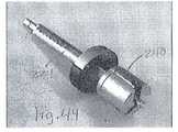
도 43은 본 발명의 슬개골 클램프의 사시도이다.
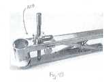
도 44는 도 43의 슬개골 클램프를 갖는 리머 축의 사시도이다.
도 45는 측정 슬리브가 부착된 리머 축의 사시도이다.
도 46은 슬개골 클램프에 대해 위치된 리머 축의 사시도이다.
도 47은 축 칼라가 부착된 리머 축의 사시도이다.
도 48은 슬개골 클램프에 대해 위치된 도 47의 리머 축과 부착된 칼라의 사시도이다.
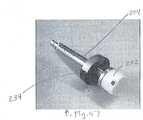
도 49는 일 단부에 리머를 갖는 리머 축의 사시도이다.
도 50은 시멘트 클램프의 사시도이다.
도 51은 슬개골 클램프에 대해 위치된 시멘트 클램프의 사시도이다.BRIEF DESCRIPTION OF THE DRAWINGS The present invention will be described in detail with reference to the accompanying drawings, wherein like reference numerals are used for like components.
BRIEF DESCRIPTION OF THE DRAWINGS Figure 1 is a schematic diagram of a representative sphere relating to the femur according to the present invention.
2 is a perspective view of one embodiment of the mechanical shaft discovery device of the present invention positioned against the femur;
Figure 3 is a perspective view of a guide pin positioned at a typical location of the femur.
4 is a perspective view of an alignment guide positioned relative to the femur;
5 is a top view of the femur showing that the alignment rod is positioned parallel to the mechanical axis when viewed in a coronal view;
Figure 6 is a side view of the femur showing the alignment rod in the sagittal plane is located on the same line as the mechanical axis.
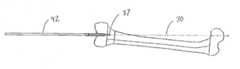
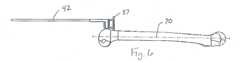
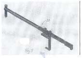
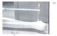
Fig. 7 is a perspective view of a mechanical axis detecting device of the tibia.
8 is another perspective view of the mechanical axis detecting device of the tibia.
Figure 9 is a perspective view of a mechanical axis finding device of a tibia positioned relative to a typical femur and tibia.
10 is a side view of one end of a mechanical axis finder of a tibia, which is located against a typical tibia and has a pointer at its distal end.
11 is yet another side view of one end of the mechanical axis finder of the tibia, which is located against a typical tibia and has a pointer at its distal end.
12 is a perspective view of a mechanical axis finding device of a tibia having a pointer at its distal end when positioned against a typical tibia;
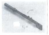
13 is a perspective view of a typical tibia and femur having a plurality of extension pins.
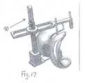
14 is a perspective view of a femur size measuring instrument.
15 is a perspective view of a femur size measuring instrument positioned relative to a typical femur having a plurality of extension pins.
Figure 16 is a perspective view of a femur size measuring instrument positioned against a portion of a knee implant.
Figure 17 is another perspective view of a femur size measuring instrument positioned against a portion of a knee implant.
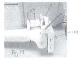
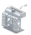
18 is a perspective view of a jawbone alignment jig positioned relative to a typical femur.
19 is a perspective view of a femoral osteotomy block and a femoral block alignment jig positioned relative to a typical femur.
20 is a side view of a cut end of a typical femur placed against the osteotomy block;
21 is a perspective view of an embodiment of a femoral osteotomy block according to the present invention.
22 is a perspective view of an embodiment of a femoral osteotomy block according to the present invention.
23 is a perspective view of a portion of a femoral osteotomy block such as the type shown in Fig.
24 is a perspective view of a portion of a femoral osteotomy block such as the type shown in Fig.
25 is a perspective view of a tibia osteotomy block according to an embodiment of the present invention.
26 is a perspective view of a tibia osteotomy jig according to an embodiment of the present invention.
Fig. 27 is a perspective view of a tibia osteotomy jig located at one end of a typical tibia. Fig.
28 is a perspective view of a C-clip according to an embodiment of the present invention.
29 is a side view of a spreader according to an embodiment of the present invention.
30 is a perspective view of the tibia osteotomy block and the femoral osteotomy block.
31 is a side view of the tibia osteotomy block and the femoral osteotomy block.
32 is a perspective view of the femoral osteotomy block having the apparatus for attaching the scorpion tail according to the present invention.
33 is another perspective view of a femoral osteotomy block having a scorpion tail attaching device of the present invention and positioned against the knee.
34 is a perspective view of various components of a total knee arthroplasty device used in accordance with the present invention, including a spreader;
35 is a side view of a box reamer in a first position with a femoral osteotomy block;
37 is a perspective view of a box reamer in a second position with the femoral osteotomy block.
38 is another perspective view of a femoral osteotomy block and a box reamer.
39 is a perspective view of a chisel positioned relative to a femoral osteotomy block;
40 is a perspective view of a fin punch of the tibia.
41 is a perspective view of a part of the test femur component.
Figure 42 is a perspective view of the tibial insert for use.
Figure 43 is a perspective view of the patella clamp of the present invention.
Figure 44 is a perspective view of the reamer shaft with the patella clamp of Figure 43;
45 is a perspective view of a reamer shaft with a measuring sleeve attached;
Figure 46 is a perspective view of the reamer shaft positioned relative to the patella clamp.
47 is a perspective view of a reamer shaft with a shaft collar attached thereto;
Figure 48 is a perspective view of the reamer shaft and attached collar of Figure 47 positioned against the patella clamp.
49 is a perspective view of a reamer shaft having a reamer at one end;
50 is a perspective view of the cement clamp.
51 is a perspective view of the cement clamp positioned against the patella clamp;
합당한 성공률로 사용되어온 수많은 무릎관절 전치환술 시스템이 존재하며, 각 시스템은 상이한 장치 세트와 각 세트에 수반되는 상이한 기술을 포함한다. 이 시스템들을 사용할 때 부딪치는 몇몇 문제점은, 우선은 일반적으로 다음에는 특정 실시예와 관련하여 후술될 본 발명의 방법, 시스템 및 장치를 사용하면 존재하지 않는다.There are a number of total knee arthroplasty systems that have been used with reasonable success rates, and each system includes a different set of devices and the different techniques involved in each set. Some of the problems encountered when using these systems do not exist at first, generally using the methods, systems and devices of the present invention, which will be described below in connection with specific embodiments.
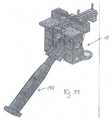
무릎관절 전치환술 수술의 일차적인 목표는 하지(下肢)를 적절히 정렬하는 것이다. 이러한 정렬은 (1) 대퇴골두의 중심, (2) 무릎의 중심, 및 (3) 발목의 중심을 포함하는 세 지점에 의해 안내된다. 무릎의 중심과 발목의 중심은 수술 중에 접급할 수 있기 때문에, 이들 지점을 발견하는 것은 상대적으로 간단하다. 그러나 대퇴골두는 엉덩이 깊이 있으며 수술 영역 밖에 있다. 개발되어온 많은 시스템이 대퇴관(femoral canal)으로 삽입되는 가이드 로드를 사용하되, 각도 상 평균값으로 도달하도록 사용되며 대퇴골두를 지향한다고 가정될 기준 구조물로서 이 가이드 로드를 이용한다. 또한, 일부 시스템은 대퇴골두를 찾기 위해 수술전 x-레이를 사용하여 수술 중에 수술의가 촉진할 수 있는 물리적 마커를 위치시킨다. 또 다른 시스템은 대퇴골두를 찾기 위해 고가의 컴퓨터 항법장치를 이용한다. 그러나 본 발명에 따르면, 여기서 기술될 시스템의 실시예들은 방사선 또는 고가의 장비를 요구하지 않는 역학적 축 발견장치를 이용한다.The primary goal of total knee arthroplasty is to align the lower limbs properly. This alignment is guided by three points, including (1) the center of the femoral head, (2) the center of the knee, and (3) the center of the ankle. It is relatively simple to find these points because the center of the knee and the center of the ankle can be accessed during surgery. However, the femoral head is deep in the hips and is outside the surgical area. Many of the systems developed use a guide rod that is inserted into the femoral canal, but this guide rod is used as a reference structure to be used to reach the angular mean value and to assume the femoral head. In addition, some systems use pre-operative x-rays to locate physical markers that can facilitate surgery during surgery to find the femoral head. Another system uses an expensive computer navigation device to find the femoral head. However, in accordance with the present invention, embodiments of the systems described herein utilize mechanical shaft detection devices that do not require radiation or expensive equipment.
성공적인 무릎관절은 뼈를 고정하는 인대들이 균형잡힐(balanced) 것을 또한 요구하며, 본 발명에 따르면 이는 모든 뼈 절단 전에 수행된다. 즉, 초기에 일단 무릎 인대가 균형잡히면, 본 발명의 뼈 절골 지침자는 각 인대의 표면에 위치된 후 절단이 수행된다. 또한, 본 발명의 실시예에서, 무릎관절이 일 위치에서 대퇴골을 절단하고 다른 위치에서 경골을 절단하는 다른 시스템과 달리, 모든 뼈 절단은 하나의 위치에서 행해진다. 끝으로, 본 발명의 장치와 방법을 사용하여 행해진 절단은 보다 정확하여서 필요 이상으로 많은 절단에 기인할 수 있는 어떠한 합병증의 가능성도 최소화할 것이다.A successful knee joint also requires that the ligaments that fix the bones are balanced, and according to the present invention this is done prior to all bone cutting. That is, once the knee ligaments are initially balanced, the bone osteotomy guidelines of the present invention are performed posteriorly, located on the surface of each ligament. Also, in an embodiment of the present invention, unlike other systems where the knee joints cut the femur at one position and cut the tibia at another position, all bone cutting is done in one location. Finally, the cuts made using the apparatus and methods of the present invention will be more accurate and will minimize the likelihood of any complications that can result from more than necessary cuts.
동일한 구성부에 대해서 동일한 참조번호를 사용하는 도면들을 참조하여, 본 발명에 따른 무릎관절 전치환술을 위한 여러 단계들이 예시 및 기술될 것이다. 수술의 준비로, 외과의에 의한 접근을 위해 적절한 수술용 드레이프(surgical drapes) 및 발/발목 포지셔너(positioner)를 사용하여 무릎을 원하는 상태로 위치시킨 후에 수술처치가 수행될 수 있다.Referring to the drawings, which use the same reference numerals for the same components, various steps for a total knee replacement according to the present invention will be illustrated and described. In preparation for surgery, surgical procedures may be performed after placing the knee in the desired position using appropriate surgical drapes and foot / ankle positioner for access by the surgeon.
수술을 시작하기 위해, 환자의 무릎이 노출된다. 이 단계에서, 전방 십자인대(ACL)와 내측 측부인대(MCL), 및 양 반월판(menisci)이 제거될 수 있도록 무릎을 노출시키기 위해 내측 슬개주위 절개(medial parapatellar incision)가 사용된다. 접근할 수 있는 어떠한 뼈돌기(osteophyte)도 역시 제거된다. 슬개골을 측부로 이동시킨다.To begin the operation, the patient's knee is exposed. At this stage, a medial parapatellar incision is used to expose the knee so that the ACL, medial collateral ligament (MCL), and bilateral menisci can be removed. Any accessible osteophyte is also removed. Move the patella to the side.
다음으로, 대퇴골 역학적 축이 설정되며, 이는 여러 방법을 사용하여 수행할 수 있는바, 본 발명의 하나의 방법은 2013년 2월 8일에 출원된 미국 가출원 제61/762,492호에 개시된 역학적 축 발견장치를 사용하는 것을 포함하며, 상기 출원의 내용이 참조에 의해 여기에 포함된다. 일반적으로, 이 방법을 이용한 역학적 축의 설정은 도 1-6에 예시된 바와 같이, 환자의 대퇴골에 대해 공간에 특정 지점들의 결정을 포함한다. 먼저 도 1을 참조하면, 대퇴골(50)과 구(52)의 일부의 개략적인 다이아그램이 도시되어 있다. 구(52)와 대퇴골(50)은 대퇴골두의 중심(54)이 구(52)의 중심(58)과 일치하도록 위치된다. 또한, 무릎의 중심(56)은 구(52)의 표면상에 있다. 따라서, 구(52)는 대퇴골두의 중심(54)으로부터 무릎의 중심(56)까지의 거리와 같은 반경을 갖는다.Next, a femoral ephemeral axis is established, which can be accomplished using a variety of methods, one method of the present invention is the use of a mechanical shaft discovery as disclosed in U. S. Provisional Application No. 61 / 762,492, filed Feb. 8, 2013 Device, the contents of which are incorporated herein by reference. Generally, the setting of the mechanical axis using this method involves the determination of specific points in space for the femur of the patient, as illustrated in Figures 1-6. Referring first to FIG. 1, a schematic diagram of a portion of a
본 발명에 따르면, 대퇴골의 역학적 축을 설정하려고 시도할 때 흔히 만나게 되는 문제들이, 도 1에 도시된 바와 같이, 제1 지점(60), 제2 지점(62) 및 제3 지점(64)과 같은 구의 표면상의 지점들을 사용하여 구(52)의 중심(58)을 관통하는 선을 발견함으로써 해결될 수 있다. 이러한 선을 설정하는 것은 본 발명의 장치 및/또는 방법을 사용하여 달성될 수 있다. 또한, 본 발명에 따르면, 무릎의 물리적 운동은 대퇴골두의 중심에 대해 삼차원으로 축회전하는 것으로 가정된다. 따라서 무릎의 중심(56)은 무릎이 움직여질 때 구(52)의 표면을 따르게 될 것이며, 이로 인해 무릎은 지점들(60,62,64)을 통과한다.According to the present invention, problems that are commonly encountered when attempting to set the mechanical axis of the femur are such that the
임의의 구에 있어, 구 상의 적어도 세 지점에 의해 정의된 원의 중심을 통과하며 이 원의 평면에 수직한 선은 구의 중심을 통과한다. 본 발명에 적용하면, 지점(60,62,64)은 구(52)의 표면상에 있으며, 중심(68)을 갖는 원(66)을 정의하는데 사용된다. 특정 대퇴골에 대한 역학적 축(70)을 설정하기 위해, 무릎의 중심(56)은 공간의 임의의 지점, 즉 제1 지점(60)에 해당하는 지점으로 이동된다. 다음으로, 무릎의 중심(56)은 제2 지점(62)으로 이동되고 마지막으로 제3 지점(64)으로 이동된다. 세 지점(60,62,64)은 원(66)을 정의하는데 사용되며, 지점(68)은 원의 중심으로 식별될 수 있다. 이들 지점 모두가 식별 및/또는 설정된 후, 원(66)을 포함하는 평면에 수직하며 원(66)의 중심(68)을 지나는 축(72)이 식별될 수 있다. 무릎의 중심을 축(72)과 일치하도록 이동함으로써 대퇴골(50)의 역학적 축(70)이 축(72)과 동선이 되어서 위치설정이 되도록 한다. 본 발명의 장치 및 방법은 대퇴골과 관련하여 지점(60,62,64) 및 축(72)을 식별하는데 사용되고 대퇴골의 역학적 축을 설정하는데 사용되며, 아래의 문단에서 설명된다.In any sphere, a line perpendicular to the plane of the circle passing through the center of the circle defined by at least three points on the sphere passes through the center of the sphere. In accordance with the present invention, points 60, 62, 64 are on the surface of the
도 2를 참조하면, 본 발명의 역학적 축 발견장치(1)의 실시예는 베이스(2), 연장 암(3), 회전 암(4), 및 위치설정 암(5)을 포함한다. 환자의 대표적인. 즉 예시적인 대퇴골(50) 역시 발견장치(1)에 인접하여 도시되어 있다. 베이스(2)는 작업 테이블의 측부에 고정하거나 다른 부착 구조 또는 역학적 축 발견장치와 테이블 사이의 안전한 맞물림을 제공하는 다른 부착 구조들을 사용하여 테이블에 부착될 수 있다. 도 2에 예시된 타입의 역학적 축 발견장치를 사용하는 예시적인 방법으로, 무릎관절이 노출된 후, 수술의는 관상면 및 시상면에서의 무릎의 중심(56)을 식별한다. 원한다면, 이 무릎의 중심을 식별하기 위해 무릎 중심 로케이터(knee center locator) 장치가 사용될 수 있다. 본 명세서에서 언급되는 "시상면"은 무릎의 중심을 지나며 해부학적인 시상면에 평행한 면이라는 것을 유의해야 할 것이다.2, an embodiment of the mechanical shaft detection device 1 of the present invention includes a
일단 무릎의 중심(56)이 설정되면, 도 3에 도시된 바와 같이, 핀(30)(선택에 따라서 비드, 밴드, 또는 다른 위치설정 장치를 포함할 수 있음)이 대략적으로 대퇴골의 해부학적 축에 수직하며 무릎의 중심(56)을 통과하는 시상면을 따라, 원위의 대퇴골의 전방영역 내로 삽입된다. 핀의 위치설정 장치가 무릎의 중심(56)으로부터 예정된 거리에 있도록 핀(30)이 삽입된다. 위치설정 장치의 이 위치와 대퇴골드의 중심(54)은 대퇴골두의 중심(54)으로부터 위치설정 장치의 중심까지 연장되는 대퇴골의 "대략적인 역학적 축"을 정의하는데 사용된 2지점이다.Once the
역학적 축 발견장치(1)는 전술한 특정 지점들을 설정하기 위해 서로에 대해 이동가능하며/또는 고정될 수 있는 여러 구성부 및 장치를 포함한다. 일단 이들 단계가 수행되면, 도 3에 도시된 바와 같이, 핀(30)의 위치설정 장치는 브라켓과 결합되고 대퇴골은 가이드 핀(37)이 핀(30)에 대해 예정된 거리/위치의 대퇴골(50) 내로 천공될 수 있도록 위치되며, 이러한 방식에서 진정한 역학적 축(70)과 개략적인 역학적 축 사이의 각이 보상된다. 따라서, 핀(37)은 대퇴골(50) 내로 천공될 때 도 1 및 2의 축(70)에 수직하다.The mechanical axis detection device 1 includes various components and devices that can be moved and / or fixed relative to each other to set the above-mentioned specific points. 3, the positioning device of the
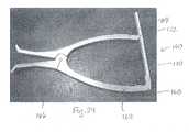
다음에는 역학적 축 발견장치(1)가 도 3에 도시된 바와 같이 가이드 핀(30,37)을 대퇴골(50)의 각 위치에 위치시킨 채로 환자로부터 제거된다. 다음에는 로드 정열 가이드(39)가 도 4에 도시된 바와 같이 핀(30,37) 위에 위치된다. 특히, 로드 정렬 가이드(39)는 핀(37) 위로 활주할 수 있는 가이드 구멍과, 핀(30) 위로 활주할 수 있는 가이드 슬롯을 포함한다. 끝으로, 정렬 로드(42)가 로드 정렬 가이드(39)의 가이드 구멍 내로 위치된다. 정렬 로드(42)는 도 5와 6에 도시된 바와 같이 관상면에서 보면 역학적 축(70)과 동선이며 시상면에서 보면 역학적 축(70)에 평행할 것이다. 가이드 핀(37)은 시상면에서 보면 역학적 축(70)에 수직할 것이다. 위치설정 장치와 가이드 핀(37)의 축을 연결하는 선은 관상면에서 보면 역학적 축과 동선이 될 것이다.Next, the mechanical shaft detecting device 1 is removed from the patient while the guide pins 30 and 37 are positioned at the respective positions of the
처치의 다음 단계에서, 연한조직 이완이 수행되고 경골의 역학적 축이 설정되며, 이러한 처치는 도 7과 8에 예시된 타입의 경골의 역학적 축 발견장치(80)를 사용하여 수행될 수 있다. 이러한 경골의 역학적 축 발견장치가 도 9-13에 예시되어 있다. 특히, 경골의 역학적 축 발견장치(80)는 전술한 2개의 전방 대퇴골 핀(30,37) 상에 위치된다. 이렇게 하여, 이 장치는 대퇴골두의 중심으로부터 무릎의 중심을 통과하여 발목의 중심까지의 올바른 역학적 축의 전체 최하단을 형성할 대퇴골의 역학적 축의 연장부가 될 것이다. 다음에는 적절한 연한조직 이완(예를 들면, 외측 이완, 등)이 무릎에서 수행되어 발목이 경골의 역학적 축 발견장치의 원위 선단(distal tip)과 동일한 선이 되도록 함으로써 하지를 올바른 역학적 축에대해 효과적으로 정렬시키며, 이것은 양호한 무릎관절 전치환술에서의 기본적 목표의 하나이다.In the next step of the procedure, a soft tissue relaxation is performed and the mechanical axis of the tibia is set, and this treatment can be performed using the tibial mechanical
경골의 역학적 축 발견장치(80)는 그 길이가 경골의 길이와 맞도록 조절될 수 있는 신축자재 부재(telescoping member)를 포함할 수 있다. 또한, 경골의 역학적 축 발견장치(80)는 시상면을 따라 조절될 수 있다. 즉, 경골의 역학적 축 발견장치(80)는 촉진할 수 있는 비골(fibula)에 평행하게 하거나 경골의 전방영역에대해 적절한 각도로 위치시킴으로써 시상면을 따라 정렬된다. 축회전 가능한 포인터(82)가 그 선단이 경골의 역학적 축 발견장치(80)를 발목의 중심에 대해 정렬시키는데 사용될 수 있도록 하방으로 회전가능하다. 일단 이것이 수행되면, 2개의 나사부가 형성된 핀(84,86)이 적절한 가이드(도 12 참조)를 통해 위치되어서 종국에는 2개의 핀(84,86)은 경골 상에 적절히 위치되고 2개의 핀(30,37)은 대퇴골 상에 적절히 위치된다. 또한, 모든 핀은 각각의 관상면 및 시상면에서 올바르게 정렬된다.The tibial mechanical
도 14-24를 참조하면, 처치의 다음 단계는 대퇴골의 크기를 측정하고 대퇴골 절골 블록을 대퇴골의 원위 단부에 적용하는 것을 포함한다. 이를 위해, 무릎이 대략 90도로 굴곡된 후 대퇴골 크기 측정기가 대퇴골 핀을 통해 위치된다. 대퇴골 크기 측정기(90)의 예시적인 실시예가 도 14,16 및 17에 도시되어 있으며, 대퇴골에 대한 크기 측정기(90)의 위치가 도 15에 도시되어 있다. 대퇴골 크기 측정기(90)는 원위 선단(94)을 갖는 상부 부재(92)와, 대퇴골의 크기에 맞추어 조절하도록 포스트(98)에 대해 활주할 수 있는 하부 부재(96)를 포함한다. 이들 부재(92,96)는 캘리퍼처럼 사용되어서, 부재(92)의 원위 선단은, 예를 들면, 측정을 위한 원하는 기준점을 제공하도록 핀(37)과 결합할 수 있다. 또는, 측부인대(collateral ligament)를 긴장시키고 대퇴골이 경골에 대해 적절히 회전 및 배치시키기 위해 전술한 크기측정 단계가 무릎이 굴곡된 채로 대퇴골 및 경골을 벌린 후에 수행될 수 있다. 도 29에 도시된 바와 같이, 스프레더(spreader), 즉 "잭-업 장치(jack-up device)가 이 목적을 위해 사용될 수 있다. 대퇴골의 크기 측정은 경골의 역학적 축에 평행한 방향으로 수행된다.Referring to Figures 14-24, the next step in the procedure involves measuring the size of the femur and applying the femoral osteotomy block to the distal end of the femur. To this end, the knee is bent approximately 90 degrees, and then the femur sizer is positioned through the femoral pin. An exemplary embodiment of the femur
일단 대퇴골의 크기를 알면, 측정기(90)를 제거하고 상응하는 크기의 대퇴골 절골 블록 또는 지그로 대체하며, 이 장치는 도 18에 도시된 절골 블록 정렬 지그(100)를 통해 2개의 전방 대퇴골 핀(30,37)에 연결된다. 절골 블록 정렬 지그(100)는 절골 블록(110)이 대퇴골의 역학적 축에 수직한 면을 중심으로 회전운동 및 병진운동하도록 한다. 절골 블록(110)은 연장 플랜지(102)를 통해 정렬 지그(100)에 부착될 수 있으며, 절골 블록(110)의 슬롯이 연장 플랜지 상으로 활주할 수 있다.Once the size of the femur is known, the measuring
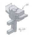
본 처치에 사용될 수 있는 대퇴골 절골 블록의 실시예가 조립 및 분해된 상태로 도 19-24에 도시되어 있다. 특히, 도 21과 22는 조립된 상태의 절록 블록(110)을 보여주며, 도 23과 24는 각각 절골 블록(110)의 별도의 블록 피스(112,114)를 보여준다. 블록 피스(112)는 절골 블록이 대퇴골에 대해 특정의 예정된 위치에 있을 때 절단 날이 원하는 위치에서 뼈를 절단하도록 삽입되는 복수의 슬롯(116)을 포함한다. 도 19는 절골 블록 정렬 지그(100)에 부착되었을 때의 절골 블록(110)의 위치를 보여준다. 이 절골 블록(110)이 이러한 방식으로 위치될 때, 절골 블록은 대퇴골에 대해 올바른 내반-외반 각(varus-valgus angle)(관상면) 및 올바른 굴곡-신전 각(flexion-extension angle)(시상면)에 있게 될 것이다.An embodiment of a femoral osteotomic block that can be used in the present treatment is shown in Figures 19-24 in an assembled and disassembled state. In particular, FIGS. 21 and 22 show the assembled
절골 블록(110)이 적절히 위치된 후, 원위 대퇴골이 절록 블록(110)의 예정된 슬롯(116)을 통해 압박되는 절단 날을 사용하여 절단된다. 도 20은 절단 과정에 의해 원위 단부가 제거된 대퇴골을 보여준다. 다음에는 절골 블록(110)이 대퇴골의 절단면과 접하도록 전진, 즉 접철된다. 대퇴골의 이 절단은 대퇴골 절골 블록(110)이 후속 절단을 위해 접철되도록 다른 절단 전에 수행되는 한 번의 원위 절단이다. 또한, 원위 절단은 (절골 블록의 상응하는 변형에 의해) 절골 블록(110)의 접철이 없이 모든 다른 절단과 함께 수행될 수도 있으나, 절골 블록(110)이 본래의 원위 관절구(condyle)의 일반적으로 둥근 형상에 접하는 대신에 대퇴골의 평평한 원위 절단면과 평행하게 위치되고 핀으로 고정된다면 보다 안정할 수 있다.After the
다음으로, 도 26과 27에 도시된 경골 절골 지그(120)가 이미 경골에 위치되어 있던 2개의 핀(84,86) 상으로 활주된다. 다음에는 경골 절골 블록(130)이 경골 절골 지그(120)에 대해 위치될 수 있다. 이것은 경골 절골 블록(130)을 경골과 관련하여 올바른 내반-외반 각(관상면)과 올바른 굴곡-신전 각(시상면)에 위치시킨다.Next, the
전술한 바와 같이, 공지된 시스템은 경골과 대퇴골의 절단을 별도로 수행하며, 뼈들의 절단 후에 두 뼈를 상관, 즉 매치시킨다. 그러나 본 발명에 따른 무릎관절 전치환술 시스템 및 방법은 뼈의 절단 전에 뼈들을 매치시킨다. 이러한 과정을 위해, 적어도 하나의 전방 기준 가이드 "스콜피온 테일"(도 32와 33에 도시됨), C-클립(도 28에 도시됨), 및 스프레더(도 29에 도시됨)을 포함하는 수많은 구성부들이 사용되며, 이들이 후술된다.As described above, the known system performs the cutting of the tibia and the femur separately and correlates or matches the two bones after the cutting of the bones. However, the system and method of the total knee arthroplasty according to the present invention match the bones before cutting the bone. For this process, a number of configurations, including at least one forward reference guide "scorchion tail" (shown in Figures 32 and 33), a C-clip (shown in Figure 28), and a spreader Parts are used, which will be described later.
특히, 도 32와 33은, 대퇴골 전방 피질(antetrior femoral cortex)에 대해 전방-후방 방향을 따라 대퇴골 절골 블록을 위치시키기 위해 대퇴골 절골 블록에 부착될 수 있는, 여기서는 "스콜피온 테일"(140)로 불리는 부착구를 도시한다. 이 스콜피온 테일 부착구(140)는 전방 절단을 한정하며 대퇴골 전방 피질의 파임(notching)을 방지한다. 다음에는, 도 30과 31에 도시된 바와 같이, C-클립(150)이 대퇴골 절골 qffhr과 경골 절골 블록을 연결하기 위해(즉, 대퇴골과 경골이 평행하도록 매치시키기 위해) 응용된다. C-클립(150)의 일 실시예가 여기에 도시되나, 수술의가 각 특정 환자에 맞게 선택할 수 있는 다수의 C-클립을 제공할 수 있다는 것을 이해할 것이다. C-클립(150)은 굴곡 갭을 한정하며, 경골 고평부의 요구된 양만을 절단하도록 경골 절골 블록(130)을 위치시킨다. 따라서, C-클립(150) 역시 사용될 경골 임플란트 구성부의 두께를 결정한다. C-클립(150)은 상이한 경골 임플란트 구성부의 두께에 상응하는 여러 갭 크기에 들어갈 수 있다.In particular, Figures 32 and 33 illustrate the use of a so-called "scorpion tail" 140, which can be affixed to the femoral osteotomy block to position the femoral osteotomy block along the anterior-posterior direction with respect to the antitorial femoral cortex FIG. This
도 29에 도시된 장치와 같은, 스프레더, 즉 "잭-업 장치"(160)가 경골극(tibial spine)과 과간절흔(intercondylar notch) 사이에 위치된다. 스프레더(160)는 회전 점(166)에 상호 축회전할 수 있도록 연결되는 제1 및 제2 아암(162,164)을 포함한다. 제1 아암(162)의 원위 단부(168)는 아암(164)의 원위 단부(172)와 맞물릴 수 있는 연장 래칫 부재(extenting ratchet member)(170)를 포함하며, 따라서 장치는 원하는 스프레딩 기능(spreading function)을 구비한다. 특히, 절골 블록들의 어느 것도 이 스프레더(160)를 원하는 위치에 위치시키기 위해 제거될 필요가 없다. 아암(162,164)의 핸들, 즉 근위 단부는 서로를 향해 압착되어서, 예를 들면 도 34에 도시된 바와 같이, 양 측부 인대의 인장으로 인해 대퇴골을 올바른 각도로 회전시킨다. 이 경우에, 스프레더(160)를 사용한 조정은 래칫 부재(170)를 래칭(ratcheting)하여 아암(162,164)을 상호 고정하며 대퇴골이 회전하도록 하여 대퇴골 절골 블록을 대퇴골에 대해 올바른 회전위치에 있게 하는 것을 포함한다.A spreader, or "jack-up device" 160, such as the device shown in Figure 29, is positioned between the tibial spine and the intercondylar notch. The
이 스프레딩 단계 중에, 대퇴골 절골 블록은 C-클립에 의해 경골 절골 블록에 평행하게 유지된다. 동시에, 도 18의 절골 블록 정렬 지그에 의해 대퇴골의 역학적 축에 수직하게 유지된다. 이러한 조정은 다른 시스템에서처럼 일정한 회전량(예를 들면, 3-5도의 회전)을 사용하는 대신에 각 환자에 따라 개별적인 조정을 제공한다. 올바른 대퇴골 회전은 더욱 균형잡힌 굴곡 갭, 더 나은 범위의 움직임 및 더 나은 슬개고 주행을 허용한다. 일단 대퇴골 절골 블록(110)과 경골 절골 블록(130)의 올바른 위치기 수립되면, 양자는 핀을 사용하여 고정된다. 다음에는 스콜피온 테일 부착구(140), 스프레더(160) 및 C-클립이 제거된다.During this spreading step, the femoral osteotomy block is held parallel to the tibial osteotomic block by a C-clip. At the same time, it is held perpendicular to the mechanical axis of the femur by the jibbing block alignment jig of Fig. This adjustment provides individual adjustments for each patient instead of using a constant amount of rotation (e.g., 3-5 degrees of rotation) as in other systems. Proper femoral rotation allows for a more balanced bend gap, better range of motion, and better patellar running. Once the
이 상태에서 절골 지그 또는 블록은 각각의 뼈에 대해 원하는 위치에 있게 될 것이다. 전술한 것과 같이, 왕복 톱을 사용하여 원위의 대퇴골이 절단되고, 대퇴골 절골 블록이 절단면 상으로 전진된다. 다음에는 절골 블록(110)의 가이드(즉, 슬롯(116))를 이용하여 아래와 같은 절단을 수행한다; 전방 대퇴골 절단, 전방 모따기, 후방 절단, 및 후방 모따기. 일 실시예에서, 박스의 "지붕", 즉 근위면과 원위 대퇴골이 먼저 절단되고, 절골 블록이 밀려지며, 즉 절단된 원위 대퇴골 상으로 접철되며, 핀으로 고정된다. 여기서 "박스 리머(box reamer)"로 언급되는 장치가 박스 절단을 하기 위해 사용되는바, 박스 리머(180)의 일 실시예가 도 35-37에 도시되어 있으며 도 38에는 대퇴골 절골 블록과 관련되어 도시되어 있다. 또는, 박스의 측부를 절단하기 위해 왕복 톱이 사용될 수 있다. 박스를 절단하기 위해 박스 끌 또는 유사한 장비가 또한 사용될 수 있다. 절단 단계의 또 다른 순서로, 원위 대퇴골이 절단된 후 박스가 절단된다. 전방 및 후방 모따기는 원한다면 각각의 전방 및 후방 절단 전 또는 후에 행해질 수 있다. 다음에는 가이드로서 경골 절골 블록을 사용하여 경골이 절단된다. 도 39에 도시된 타입의 끌(190)이 임플란트를 위한 "험프(hump)"를 절단학 위해 사용될 수 있으며, 대퇴골 절골 블록(110)에 대한 끌(190)의 예시적인 위치가 역시 도시되어 있다. 또는, 적절한 프로파일을 갖는 뼈 줄(rasp)이 "험프"를 절단하기 위해 사용될 수 있다.In this state, the osteotomized jig or block will be in a desired position for each bone. As described above, the distal femur is cut using the reciprocating saw, and the femoral osteotomy block is advanced onto the cut surface. Next, using the guide (i.e., slot 116) of the
다음으로, 절골 지그 또는 블록이 제거되며, 경골 천공 가이드가 위치되어 핀으로 고정되며, 경골 기준 핀이 제거된다. 다음에는 경골이 천공되고 경골 천공 가이드가 제거된다. 다음에는 시용 경골 베이스 플레이트(base plate)가 뼈의 절단 부위에 적용된다.Next, the osteotomized jig or block is removed, the tibial perforation guide is positioned and fixed to the pin, and the tibial reference pin is removed. Next, the tibia is punctured and the tibial perforation guide is removed. Next, a tibia base plate is applied to the cutting site of the bone.
있다면, 후방 뼈돌기를 제거하고 특정 환자에 대해 올바른 크기를 갖도록 선택된 시용 대퇴골 구성부를 원위의 대퇴골에 위치시킨다. 예시적인 시용 대퇴골 구성부(200)가 도 41에 도시되어 있다. 상응하는 올바른 크기의 시용 경골 삽입물이 전술한 C-클립 크기에 의해 결정된 바와 같은 삽입물의 올바른 두께로 근위 경골에 적용된다. 시용 구성부 두께는 예를 들면 도 42에 예시된 바와 같은 타입의 조절형 시용 경골 삽입물(210)을 사용함으로써 무릎으로부터 제거하지 않고 증가될 수 있다. 시용 경골 삽입물(210)은 포스트(216)를 Ejk라 하부 피스(214)에 대해 조절될 수 있는 상부 피스(212)를 포함한다. 피스들(212,214)이 상호 원하는 거리로 위치될 때까지의 이들의 이동은 최종 경골 구성부에 대해 요구되는 두께에 해당할 것이다. 또는, 일정 두께를 갖는 시용 경골 구성부가 사용될 수 있다. 다음에는 양호한 슬개골 주행으로 안정한 충분한 신전 및 안정한 굴곡을 달성하기 위한 무릎의 능력에 관한 평가가 행해진다. 정렬은 핀에 적용되는 로드에 의해 확인되며, 이 로드는 대퇴골두의 중심으로부터 무릎의 중심을 지나 발목의 중심을 지날 것이다. 부가적인 이완 및 균형잡기가 수행될 수 있다. 또한, 경골 플레이트 회전(tibial plate rotation)이 표시될 수 있으며, 경골 핀 펀치(tibial fin punch)(218)(예를 들면, 도 40 참조)가 경골에 적절한 구멍을 내기 위해 사용될 수 있다. 끝으로, 시용 구성부를 제고하고 최종 임플란트 구성부로 대체한 후, 시멘트로 고정된다.If present, remove the posterior bony prominence and place the selected femur component on the distal femur to the right size for the particular patient. An example application
슬개골 치환술이 요구되면, 본 발명에 따른 다음의 처치와 상응하는 장치가 사용될 수 있다. 먼저, 슬개골의 두께가 측정되는바, 이는 슬개골이 절단되는 평면을 설정하기 위해 도 43에 도시된 바와 같이 먼저 슬개골을 외번시키고 다음에는 슬개골 클램프(220)에 위치시킴으로써 달성될 수 있다. 다음에는 예를 들면 캐리퍼와 같은 장치로 슬개골의 두께를 측정할 수 있다. 그러나 슬개골의 불규칙한 형태로 인해, 그 두께에 해당하는 슬개골 표면상의 지점들을 연결하는 선은 절단면에 수직하지 않을 수도 있다. 이러한 경우, 정확한 측정을 위해 캘리퍼를 적절하게 위치시키는 것이 어려울 수 있다. 따라서, 본 발명에 따라, 슬개골의 두께는 (도 44에 도시된)눈금을 갖는 리머 축(224)에 부착된 (도 45에 도시된) 측정 슬리브(222)를 사용하여 측정될 수 있다. 리머 축(224)과 측정 슬리브 조립체(230)(도 45에 도시)는 슬개골 클램프로 삽입된다. 도 46에 도시된 바와 같이, 리머 축의 눈금을 사용하여 슬개골의 두께를 측정하기 위해 인디케이터 슬리브(indicator sleeve)가 사용된다.If patellar replacement is desired, a device corresponding to the following treatment according to the present invention may be used. First, the thickness of the patella is measured, which can be accomplished by first extinguishing the patella as shown in FIG. 43 to set the plane in which the patella is cut, and then placing it in the
슬개골의 두께를 측정한 후, 축 칼라(234)가 도 47에 도시된 바와 같이 리머 축(224) 위에 위치된다. 축 칼라(234)는 슬개골 클램프(220)상에 같은 높이로 압착되어 고정된다. 축 칼라(234)는 오버-리밍(over-reaming)을 방지하며 슬개골이 적절한 깊이로 확장되는(reamed) 것을 보장하기 위한 스토퍼로 작용한다. 다음에는 측정 슬리브(222)가 제거되고 도 49에 도시된 바와 같은 리머(240)로 대체된다. 다음에는 축 칼라가 슬개골 클램프의 상면과 접할 때까지 슬개골이 확장된다. 슬개골 임플란트가 맞는 것(fit)을 확인하기 위해 시용 슬개골 임플란트가 사용될 수 있다. 다음에는 슬개골 임플란트가 세멘트로 고정된다. 도 50에 도시된 바와 같은 타입의 세멘트 클램프(250)가 도 51에 도시된 바와 같이 세멘트를 경화시키는 동안 슬개골 임플란트를 위치에 유지하기 위해 슬개골 클램프(220)에 부착될 수 있다.After measuring the thickness of the patella, an
본 발명이 몇몇 실시예를 참조하여 기술되었다. 여기에 언급된 특허 또는 특허출원의 전 내용이 참조에 의해 여기에 포함된다. 전술한 상세한 설명 및 예는 단지 명료한 이해를 위한 것이다. 불필요한 한정이 없어야 한다는 것을 이해할 것이다. 본 발명의 범위를 일탈함이 없이 다양한 변형이 전술한 실시예에서 가능함을 통상의 기술자는 알 수 있을 것이다. 따라서, 본 발명의 범위는 여기에 기술된 구조물에 한정되어서는 안되며, 여기서 기술된 구조물과 그 등가물에 의해 한정되어야 할 것이다.The invention has been described with reference to several embodiments. The entire contents of the patent or patent application referred to herein are hereby incorporated by reference. The foregoing detailed description and examples are for purposes of clarity and understanding only. You will understand that there should be no unnecessary limitations. It will be appreciated by those skilled in the art that various modifications may be made in the embodiments described above without departing from the scope of the invention. Accordingly, the scope of the present invention should not be limited to the structures described herein, but should be limited by the structures described herein and their equivalents.
Claims (19)
Translated fromKorean무릎의 중심을 식별하는 단계,
무릎의 중심을 통해 원위 대퇴골 전방으로 제1 핀을 삽입하는 단계,
무릎의 중심을 기준으로 대퇴골의 역학적 축을 설정하는 단계,
적어도 하나의 부가적인 핀의 축이 대퇴골의 역학적 축과 수직으로 교차하도록 적어도 하나의 부가적인 핀을 원위 대퇴골의 전방으로 삽입하는 단계,
경골의 역학적 축을 설정하는 단계,
대퇴골의 크기를 재고 적어도 하나의 대퇴골 절골 지침자를 포함하는 대퇴골 절골 블록을 대퇴골의 원위 단부에 적용하는 단계,
적어도 하나의 경골 절골 지침자를 포함하는 경골 절골 블록을 경골의 근위 단부에 대한 절단 위치에 위치시키는 단계,
대퇴골 절골 블록을 경골 절골 블록에 대해 정렬시키는 단계,
대퇴골을 경골에 대해 정렬시키는 단계,
적어도 하나의 대퇴골 절골 지침자를 통해 대퇴골을 절단하는 단계,
적어도 하나의 경골 절골 지침자를 통해 경골을 절단하는 단계,
대퇴골 및 경골 절골 블록을 제거하는 단계, 및
대퇴골의 절단 위치에 영구 대퇴골 임플란트 구성부를 위치시키고 경골의 절단 위치에 영구 경골 임플란트 구성부를 위치시키는 단계로 구성되는 무릎관절 전치환술을 수행하는 방법.Exposing the patient ' s knee,
Identifying a center of the knee,
Inserting a first pin forward of the distal femur through the center of the knee,
Setting a mechanical axis of the femur based on the center of the knee,
Inserting at least one additional pin forward of the distal femur so that the axis of the at least one additional pin crosses perpendicularly to the mechanical axis of the femur;
Setting the mechanical axis of the tibia,
Applying a femoral osteotomy block comprising at least one femoral osteotomy guide to the distal end of the femur,
Placing a tibial osteotomy block including at least one tibial osteotomy guide at a cutting position with respect to a proximal end of the tibia,
Aligning the femoral osteotomy block with respect to the tibial osteotomy block,
Aligning the femur with respect to the tibia,
Cutting the femur through at least one femoral osteotomy guide,
Cutting the tibia through at least one tibial osteotomy guide,
Removing the femur and tibial osteotomy block, and
Positioning the permanent femoral implant component at the femur cut position and positioning the permanent tibial component implant at the tibial cut position.
무릎의 중심으로부터 예정된 거리만큼 이격된 추적지점에서 얻어지며, 그 중심이 대퇴골두의 중심과 일치하는 대표 구를 식별하는 단계,
상기 대표 구 상의 적어도 세 지점을 식별하는 단계,
대표 구 상의 상기 적어도 세 지점에 의해 정의되는 원의 중심을 설정하는 단계,
대표 구 상의 적어도 세 지점에 의해 정의되는 상기 원의 중심을 지나며 상기 원의 평면에 수직한 선을 식별하는 단계,
대표 구 상의 적어도 세 지점에 의해 정의되는 원의 중심을 지나며 이 원의 평면에 수직한 상기 선이 대퇴골두의 중심과 상기 추적지점을 연결하는 선과 일치하도록 대퇴골을 위치시키는 단계, 및
관상면 및 시상면 모두에서 대퇴골의 역학적 축의 위치를 식별하기 위해 대퇴골에 복수의 위치설정장치를 위치시키되, 이 위치설정장치는 무릎의 중심으로부터 추적지점의 예정된 이격을 보상하도록 대퇴골에 위치되어서 대퇴골두의 중심과 추적지점을 연결하는 상기 선이 대퇴골의 역학적 축으로부터 예정된 각도 이격을 갖는 단계로 구성되는 방법.The method of claim 1, wherein the step of setting the mechanical axis of the femur comprises:
Identifying a representative limb that is obtained at a tracking point spaced a predetermined distance from the center of the knee and whose center is coincident with the center of the femur head,
Identifying at least three points on the representative phrase,
Establishing a center of a circle defined by said at least three points on the representation,
Identifying lines perpendicular to the plane of the circle passing through the center of the circle defined by at least three points on the representative circle,
Positioning the femur so that the line perpendicular to the plane of the circle passing through the center of the circle defined by at least three points on the representative circle coincides with a line connecting the center of the femur head and the tracking point;
Positioning a plurality of positioning devices on the femur to identify the location of the mechanical axis of the femur in both the coronal and sagittal planes positioned on the femur to compensate for the predetermined spacing of the tracking points from the center of the knee, Wherein the line connecting the center of the femur to the tracking point has a predetermined angular separation from the mechanical axis of the femur.
Applications Claiming Priority (9)
| Application Number | Priority Date | Filing Date | Title |
|---|---|---|---|
| US201361762492P | 2013-02-08 | 2013-02-08 | |
| US61/762,492 | 2013-02-08 | ||
| US201361904099P | 2013-11-14 | 2013-11-14 | |
| US201361904086P | 2013-11-14 | 2013-11-14 | |
| US201361904083P | 2013-11-14 | 2013-11-14 | |
| US61/904,099 | 2013-11-14 | ||
| US61/904,086 | 2013-11-14 | ||
| US61/904,083 | 2013-11-14 | ||
| PCT/US2014/015269WO2014124235A1 (en) | 2013-02-08 | 2014-02-07 | Total knee arthroplasty methods, systems, and instruments |
Publications (2)
| Publication Number | Publication Date |
|---|---|
| KR20150140641Atrue KR20150140641A (en) | 2015-12-16 |
| KR102186793B1 KR102186793B1 (en) | 2020-12-04 |
Family
ID=51297966
Family Applications (2)
| Application Number | Title | Priority Date | Filing Date |
|---|---|---|---|
| KR1020157023183AExpired - Fee RelatedKR102131668B1 (en) | 2013-02-08 | 2014-02-07 | Instrument for locating a femoral mechanical axis |
| KR1020157024147AExpired - Fee RelatedKR102186793B1 (en) | 2013-02-08 | 2014-02-07 | System for performing total knee arthroplasty |
Family Applications Before (1)
| Application Number | Title | Priority Date | Filing Date |
|---|---|---|---|
| KR1020157023183AExpired - Fee RelatedKR102131668B1 (en) | 2013-02-08 | 2014-02-07 | Instrument for locating a femoral mechanical axis |
Country Status (7)
| Country | Link |
|---|---|
| US (3) | US9861486B2 (en) |
| EP (2) | EP2953559B1 (en) |
| JP (2) | JP6326069B2 (en) |
| KR (2) | KR102131668B1 (en) |
| CN (2) | CN105377163B (en) |
| PH (2) | PH12015501725B1 (en) |
| WO (3) | WO2014124233A1 (en) |
Families Citing this family (24)
| Publication number | Priority date | Publication date | Assignee | Title |
|---|---|---|---|---|
| CA2641966C (en) | 2005-12-15 | 2016-11-22 | Zimmer, Inc. | Distal femoral knee prostheses |
| CA2993979A1 (en) | 2010-09-10 | 2012-03-15 | Zimmer Gmbh | Femoral prosthesis with medialized patellar groove |
| JP6029817B2 (en)* | 2011-09-27 | 2016-11-24 | 京セラメディカル株式会社 | Total knee implant |
| US9549742B2 (en) | 2012-05-18 | 2017-01-24 | OrthAlign, Inc. | Devices and methods for knee arthroplasty |
| FR2992164A1 (en)* | 2012-06-20 | 2013-12-27 | Tornier Sa | SET OF FEMALE IMPLANTS FOR KNEE PROSTHESIS |
| US9289306B2 (en) | 2013-03-15 | 2016-03-22 | Catalyst Orthopaedics Llc | Humeral arthroplasty |
| EP2792692A1 (en) | 2013-04-17 | 2014-10-22 | Basell Poliolefine Italia S.r.l. | Nucleated propylene-based polyolefin compositions |
| US10130375B2 (en) | 2014-07-31 | 2018-11-20 | Zimmer, Inc. | Instruments and methods in performing kinematically-aligned total knee arthroplasty |
| TR201412961A2 (en)* | 2014-11-04 | 2016-05-23 | Melih Gueven | High tibial osteotomy external fixator. |
| US10582982B2 (en) | 2015-03-23 | 2020-03-10 | Zimmer, Inc. | Disposable multi-purpose tool for total knee arthroplasty |
| US10568650B2 (en) | 2015-03-25 | 2020-02-25 | E. Marlowe Goble | Knee instruments and methods |
| KR101700862B1 (en)* | 2015-08-10 | 2017-02-01 | 주식회사 코렌텍 | Method for Preparing Patient Customized Tibial Component |
| EP3355834B1 (en) | 2015-09-29 | 2023-01-04 | Zimmer, Inc. | Tibial prosthesis for tibia with varus resection |
| CN106618678B (en)* | 2017-01-24 | 2023-11-10 | 丽水市人民医院 | An infrapatellar fat pad resection device |
| CA3056495A1 (en) | 2017-03-14 | 2018-09-20 | OrthAlign, Inc. | Soft tissue measurement & balancing systems and methods |
| AU2018203343B2 (en)* | 2017-05-15 | 2023-04-27 | Howmedica Osteonics Corp. | Patellofemoral implant |
| US10940666B2 (en) | 2017-05-26 | 2021-03-09 | Howmedica Osteonics Corp. | Packaging structures and additive manufacturing thereof |
| WO2019046518A2 (en)* | 2017-08-31 | 2019-03-07 | Smith & Nephew, Inc. | Cutting guide and method |
| US10893948B2 (en) | 2017-11-02 | 2021-01-19 | Howmedica Osteonics Corp. | Rotary arc patella articulating geometry |
| US11051829B2 (en)* | 2018-06-26 | 2021-07-06 | DePuy Synthes Products, Inc. | Customized patient-specific orthopaedic surgical instrument |
| EP3846701B1 (en)* | 2018-09-04 | 2022-07-20 | Medacta International SA | Tibial resection guide device |
| CN111529138A (en)* | 2019-12-31 | 2020-08-14 | 北京力达康科技有限公司 | Total knee joint prosthesis |
| BE1028689B1 (en)* | 2021-03-12 | 2022-05-04 | Dr Philip Winnock De Grave Orthopedie | INSTRUMENT |
| DE102023119548A1 (en) | 2023-07-25 | 2025-01-30 | TRUMPF Werkzeugmaschinen SE + Co. KG | Method, vibration device and separating device for separating at least one workpiece from a residual grid part composite |
Citations (4)
| Publication number | Priority date | Publication date | Assignee | Title |
|---|---|---|---|---|
| US20050070897A1 (en)* | 2003-09-29 | 2005-03-31 | Petersen Thomas D. | Laser triangulation of the femoral head for total knee arthroplasty alignment instruments and surgical method |
| US20080195110A1 (en)* | 2007-02-13 | 2008-08-14 | Norman Plassy | Device, system and method for positioning or preparing the positioning of a medical operating instrument |
| US20090088754A1 (en)* | 2007-09-30 | 2009-04-02 | Chris Aker | Customized Patient-Specific Multi-Cutting Blocks |
| US20090222014A1 (en)* | 2001-05-25 | 2009-09-03 | Conformis, Inc. | Patient Selectable Joint Arthroplasty Devices and Surgical Tools |
Family Cites Families (41)
| Publication number | Priority date | Publication date | Assignee | Title |
|---|---|---|---|---|
| US4944760A (en)* | 1983-10-26 | 1990-07-31 | Pfizer Hospital Products Group, Inc. | Method and instrumentation for the replacement of a knee prosthesis |
| US4759350A (en)* | 1986-10-17 | 1988-07-26 | Dunn Harold K | Instruments for shaping distal femoral and proximal tibial surfaces |
| US5358527A (en)* | 1991-03-22 | 1994-10-25 | Forte Mark R | Total knee prosthesis with resurfacing and posterior stabilization capability |
| US5330534A (en) | 1992-02-10 | 1994-07-19 | Biomet, Inc. | Knee joint prosthesis with interchangeable components |
| JP3690802B2 (en) | 1993-06-21 | 2005-08-31 | ハウメディカ・オステオニクス・コーポレイション | A device that detects the functional center of the hip joint during knee arthroplasty |
| AU679242B2 (en) | 1993-06-21 | 1997-06-26 | Howmedica Osteonics Corp. | Apparatus and method for aligning knee prostheses |
| US5601566A (en) | 1994-02-22 | 1997-02-11 | Osteonics Corp. | Method and apparatus for the alignment of a femoral knee prosthesis |
| US6695848B2 (en)* | 1994-09-02 | 2004-02-24 | Hudson Surgical Design, Inc. | Methods for femoral and tibial resection |
| US5702458A (en)* | 1994-12-09 | 1997-12-30 | New York Society For The Ruptured And Crippled Maintaining The Hospital For Special Surgery | Joint prosthesis |
| US6102955A (en)* | 1995-01-19 | 2000-08-15 | Mendes; David | Surgical method, surgical tool and artificial implants for repairing knee joints |
| US5649929A (en)* | 1995-07-10 | 1997-07-22 | Callaway; George Hadley | Knee joint flexion-gap distraction device |
| US5871540A (en) | 1996-07-30 | 1999-02-16 | Osteonics Corp. | Patellar implant component and method |
| US8480754B2 (en) | 2001-05-25 | 2013-07-09 | Conformis, Inc. | Patient-adapted and improved articular implants, designs and related guide tools |
| US7635390B1 (en) | 2000-01-14 | 2009-12-22 | Marctec, Llc | Joint replacement component having a modular articulating surface |
| US6478799B1 (en)* | 2000-06-29 | 2002-11-12 | Richard V. Williamson | Instruments and methods for use in performing knee surgery |
| ES2254519T3 (en) | 2000-08-31 | 2006-06-16 | Plus Orthopedics Ag | DETERMINATION DEVICE OF A LOADING AXLE OF AN EXTREMITY. |
| DE10062580B4 (en) | 2000-12-15 | 2006-07-13 | Aesculap Ag & Co. Kg | Method and device for determining the mechanical axis of a femur |
| EP2359775B1 (en)* | 2002-02-20 | 2012-12-26 | Zimmer, Inc. | Knee arthroplasty prosthesis |
| ES2465090T3 (en)* | 2002-12-20 | 2014-06-05 | Smith & Nephew, Inc. | High performance knee prostheses |
| US20040153066A1 (en) | 2003-02-03 | 2004-08-05 | Coon Thomas M. | Apparatus for knee surgery and method of use |
| US7427272B2 (en) | 2003-07-15 | 2008-09-23 | Orthosoft Inc. | Method for locating the mechanical axis of a femur |
| US7618420B2 (en)* | 2005-02-17 | 2009-11-17 | Howmedica Osteonics Corp. | Locking intramedullary jig |
| FR2885293A1 (en)* | 2005-05-06 | 2006-11-10 | Michel Collette | INSTRUMENT OF VISEEE OF THE FEMEC MECHANICAL AXIS |
| US8070752B2 (en)* | 2006-02-27 | 2011-12-06 | Biomet Manufacturing Corp. | Patient specific alignment guide and inter-operative adjustment |
| GB0607027D0 (en)* | 2006-04-07 | 2006-05-17 | Depuy Int Ltd | Patella tracking |
| US8172842B2 (en) | 2006-07-31 | 2012-05-08 | Orthopaedic International, Inc. | Cervical plate system having an insertable rotating element |
| US7875081B2 (en)* | 2006-09-25 | 2011-01-25 | New York Society For The Ruptured And Crippled Maintaining The Hospital For Special Surgery | Posterior stabilized knee prosthesis |
| GB0622735D0 (en)* | 2006-11-15 | 2006-12-27 | Depuy Int Ltd | Locating a bone axis |
| US8313530B2 (en) | 2007-02-12 | 2012-11-20 | Jmea Corporation | Total knee arthroplasty system |
| DE102007024708B4 (en) | 2007-05-25 | 2016-11-10 | Klaus Radermacher | Device and method for determining the mechanical leg axis of a femur |
| US7892240B2 (en) | 2007-09-13 | 2011-02-22 | Zimmer, Inc. | Femoral head center locating apparatus and method |
| JP2010540126A (en) | 2007-10-06 | 2010-12-24 | ルークメディカ ピーティワイ リミテッド | Apparatus and method for assisting limb alignment |
| KR100941506B1 (en) | 2007-11-08 | 2010-02-10 | 서재곤 | Alignment Guide of Femur Fracture Guide and Femur Implant Impactor |
| US8475535B2 (en) | 2008-03-04 | 2013-07-02 | Mako Surgical Corp. | Multi-compartmental prosthetic device with patellar component transition |
| US8795282B2 (en) | 2009-01-29 | 2014-08-05 | Zimmer, Inc. | Apparatus and method for the extramedullary location of the mechanical axis of a femur |
| CA2753488C (en)* | 2009-02-25 | 2014-04-29 | Mohamed Rashwan Mahfouz | Customized orthopaedic implants and related methods |
| US9078755B2 (en)* | 2009-02-25 | 2015-07-14 | Zimmer, Inc. | Ethnic-specific orthopaedic implants and custom cutting jigs |
| JP4652481B1 (en)* | 2010-07-29 | 2011-03-16 | 浩一 金粕 | Femoral head center position identification device |
| EP2648655B1 (en)* | 2010-12-07 | 2017-06-28 | Zimmer, Inc. | Prosthetic patella |
| US8409293B1 (en)* | 2011-10-26 | 2013-04-02 | Sevika Holding AG | Knee prosthesis |
| EP2967883B1 (en)* | 2013-03-14 | 2017-11-29 | Zimmer, Inc. | Prosthetic knee implant |
- 2014
- 2014-02-07WOPCT/US2014/015265patent/WO2014124233A1/enactiveApplication Filing
- 2014-02-07CNCN201480019827.5Apatent/CN105377163B/ennot_activeExpired - Fee Related
- 2014-02-07KRKR1020157023183Apatent/KR102131668B1/ennot_activeExpired - Fee Related
- 2014-02-07USUS14/175,228patent/US9861486B2/enactiveActive
- 2014-02-07KRKR1020157024147Apatent/KR102186793B1/ennot_activeExpired - Fee Related
- 2014-02-07EPEP14748488.5Apatent/EP2953559B1/ennot_activeNot-in-force
- 2014-02-07WOPCT/US2014/015269patent/WO2014124235A1/enactiveApplication Filing
- 2014-02-07USUS14/175,208patent/US9707086B2/enactiveActive
- 2014-02-07CNCN201480018985.9Apatent/CN105307585B/ennot_activeExpired - Fee Related
- 2014-02-07JPJP2015557110Apatent/JP6326069B2/ennot_activeExpired - Fee Related
- 2014-02-07USUS14/175,235patent/US20140228964A1/ennot_activeAbandoned
- 2014-02-07JPJP2015557109Apatent/JP6326068B2/ennot_activeExpired - Fee Related
- 2014-02-07WOPCT/US2014/015276patent/WO2014124239A1/enactiveApplication Filing
- 2014-02-07EPEP14748717.7Apatent/EP2953561B1/ennot_activeNot-in-force
- 2015
- 2015-08-06PHPH12015501725Apatent/PH12015501725B1/enunknown
- 2015-08-06PHPH12015501726Apatent/PH12015501726A1/enunknown
Patent Citations (4)
| Publication number | Priority date | Publication date | Assignee | Title |
|---|---|---|---|---|
| US20090222014A1 (en)* | 2001-05-25 | 2009-09-03 | Conformis, Inc. | Patient Selectable Joint Arthroplasty Devices and Surgical Tools |
| US20050070897A1 (en)* | 2003-09-29 | 2005-03-31 | Petersen Thomas D. | Laser triangulation of the femoral head for total knee arthroplasty alignment instruments and surgical method |
| US20080195110A1 (en)* | 2007-02-13 | 2008-08-14 | Norman Plassy | Device, system and method for positioning or preparing the positioning of a medical operating instrument |
| US20090088754A1 (en)* | 2007-09-30 | 2009-04-02 | Chris Aker | Customized Patient-Specific Multi-Cutting Blocks |
Also Published As
| Publication number | Publication date |
|---|---|
| PH12015501725A1 (en) | 2015-11-09 |
| WO2014124239A1 (en) | 2014-08-14 |
| WO2014124235A1 (en) | 2014-08-14 |
| KR20150141936A (en) | 2015-12-21 |
| KR102131668B1 (en) | 2020-07-08 |
| CN105377163A (en) | 2016-03-02 |
| JP6326069B2 (en) | 2018-05-16 |
| PH12015501726B1 (en) | 2015-11-09 |
| CN105377163B (en) | 2018-04-27 |
| US9861486B2 (en) | 2018-01-09 |
| KR102186793B1 (en) | 2020-12-04 |
| JP2016506824A (en) | 2016-03-07 |
| JP6326068B2 (en) | 2018-05-16 |
| US9707086B2 (en) | 2017-07-18 |
| US20140228851A1 (en) | 2014-08-14 |
| CN105307585A (en) | 2016-02-03 |
| EP2953561A1 (en) | 2015-12-16 |
| US20140228964A1 (en) | 2014-08-14 |
| JP2016506823A (en) | 2016-03-07 |
| EP2953559A4 (en) | 2016-10-12 |
| HK1220882A1 (en) | 2017-05-19 |
| PH12015501725B1 (en) | 2019-12-04 |
| EP2953561B1 (en) | 2018-01-10 |
| PH12015501726A1 (en) | 2015-11-09 |
| US20140228852A1 (en) | 2014-08-14 |
| EP2953561A4 (en) | 2016-11-09 |
| EP2953559B1 (en) | 2018-01-31 |
| WO2014124233A1 (en) | 2014-08-14 |
| CN105307585B (en) | 2018-02-23 |
| HK1222108A1 (en) | 2017-06-23 |
| EP2953559A1 (en) | 2015-12-16 |
Similar Documents
| Publication | Publication Date | Title |
|---|---|---|
| KR102186793B1 (en) | System for performing total knee arthroplasty | |
| US5720752A (en) | Distal femoral cutting guide apparatus with anterior or posterior referencing for use in knee joint replacement surgery | |
| JP6078052B2 (en) | Bilateral knee device (BI-CRUCIATEKNEESYSTEM) | |
| US5569261A (en) | Distal femoral cutting guide apparatus with anterior or posterior referencing for use in knee joint replacement surgery | |
| EP2237729B1 (en) | Pinless system for computer assisted orthopedic surgery | |
| US20110046685A1 (en) | Surgical instrument for fitting a knee prosthesis | |
| EP0121780A1 (en) | Apparatus for shaping a distal femoral surface | |
| JP2008541914A (en) | Instrument for use in joint replacement | |
| WO1997030640A9 (en) | Distal femoral cutting guide apparatus | |
| CN108348263B (en) | Adjustable cutting block and sizing instrument for arthroplasty planning | |
| US20240390079A1 (en) | Fixation-free robotic surgery | |
| US20130053855A1 (en) | Bony balancing apparatus and method for total knee replacement | |
| US20250195082A1 (en) | System and method for tracking resection planes | |
| JP6777645B2 (en) | Double cross knee system | |
| WO2018104704A1 (en) | Apparatus for alignment of knee arthroplasty tibial cutting block | |
| WO2022192469A1 (en) | Knee instruments | |
| HK1222108B (en) | Total knee arthroplasty methods, systems, and instruments | |
| Rauh et al. | Optimizing alignment |
Legal Events
| Date | Code | Title | Description |
|---|---|---|---|
| PA0105 | International application | St.27 status event code:A-0-1-A10-A15-nap-PA0105 | |
| P11-X000 | Amendment of application requested | St.27 status event code:A-2-2-P10-P11-nap-X000 | |
| P13-X000 | Application amended | St.27 status event code:A-2-2-P10-P13-nap-X000 | |
| PG1501 | Laying open of application | St.27 status event code:A-1-1-Q10-Q12-nap-PG1501 | |
| P22-X000 | Classification modified | St.27 status event code:A-2-2-P10-P22-nap-X000 | |
| A201 | Request for examination | ||
| E13-X000 | Pre-grant limitation requested | St.27 status event code:A-2-3-E10-E13-lim-X000 | |
| P11-X000 | Amendment of application requested | St.27 status event code:A-2-2-P10-P11-nap-X000 | |
| P13-X000 | Application amended | St.27 status event code:A-2-2-P10-P13-nap-X000 | |
| PA0201 | Request for examination | St.27 status event code:A-1-2-D10-D11-exm-PA0201 | |
| E13-X000 | Pre-grant limitation requested | St.27 status event code:A-2-3-E10-E13-lim-X000 | |
| P11-X000 | Amendment of application requested | St.27 status event code:A-2-2-P10-P11-nap-X000 | |
| P13-X000 | Application amended | St.27 status event code:A-2-2-P10-P13-nap-X000 | |
| E701 | Decision to grant or registration of patent right | ||
| PE0701 | Decision of registration | St.27 status event code:A-1-2-D10-D22-exm-PE0701 | |
| GRNT | Written decision to grant | ||
| PR0701 | Registration of establishment | St.27 status event code:A-2-4-F10-F11-exm-PR0701 | |
| PR1002 | Payment of registration fee | St.27 status event code:A-2-2-U10-U12-oth-PR1002 Fee payment year number:1 | |
| PG1601 | Publication of registration | St.27 status event code:A-4-4-Q10-Q13-nap-PG1601 | |
| PR1001 | Payment of annual fee | St.27 status event code:A-4-4-U10-U11-oth-PR1001 Fee payment year number:4 | |
| PC1903 | Unpaid annual fee | St.27 status event code:A-4-4-U10-U13-oth-PC1903 Not in force date:20241201 Payment event data comment text:Termination Category : DEFAULT_OF_REGISTRATION_FEE | |
| PC1903 | Unpaid annual fee | St.27 status event code:N-4-6-H10-H13-oth-PC1903 Ip right cessation event data comment text:Termination Category : DEFAULT_OF_REGISTRATION_FEE Not in force date:20241201 |