KR20150135768A - Method and apparatus for transmitting/receiving channel state information in wireless communication system - Google Patents
Method and apparatus for transmitting/receiving channel state information in wireless communication systemDownload PDFInfo
- Publication number
- KR20150135768A KR20150135768AKR1020157022161AKR20157022161AKR20150135768AKR 20150135768 AKR20150135768 AKR 20150135768AKR 1020157022161 AKR1020157022161 AKR 1020157022161AKR 20157022161 AKR20157022161 AKR 20157022161AKR 20150135768 AKR20150135768 AKR 20150135768A
- Authority
- KR
- South Korea
- Prior art keywords
- csi
- combined
- settings
- information
- channel
- Prior art date
- Legal status (The legal status is an assumption and is not a legal conclusion. Google has not performed a legal analysis and makes no representation as to the accuracy of the status listed.)
- Withdrawn
Links
- 238000000034methodMethods0.000titleclaimsabstractdescription212
- 238000004891communicationMethods0.000titleclaimsabstractdescription35
- 238000005259measurementMethods0.000claimsdescription63
- 239000002131composite materialSubstances0.000claimsdescription5
- 230000008569processEffects0.000description147
- 230000005540biological transmissionEffects0.000description105
- 238000004364calculation methodMethods0.000description35
- FFBHFFJDDLITSX-UHFFFAOYSA-Nbenzyl N-[2-hydroxy-4-(3-oxomorpholin-4-yl)phenyl]carbamateChemical compoundOC1=C(NC(=O)OCC2=CC=CC=C2)C=CC(=C1)N1CCOCC1=OFFBHFFJDDLITSX-UHFFFAOYSA-N0.000description31
- 239000011159matrix materialSubstances0.000description25
- 238000010586diagramMethods0.000description22
- 230000011664signalingEffects0.000description16
- 229920006934PMIPolymers0.000description6
- 230000001427coherent effectEffects0.000description6
- 230000000694effectsEffects0.000description5
- 238000005516engineering processMethods0.000description5
- 238000012545processingMethods0.000description4
- 238000013468resource allocationMethods0.000description4
- 230000004044responseEffects0.000description4
- 230000006872improvementEffects0.000description3
- 238000010295mobile communicationMethods0.000description3
- 238000000794confocal Raman spectroscopyMethods0.000description2
- 125000004122cyclic groupChemical group0.000description2
- 238000011500cytoreductive surgeryMethods0.000description2
- QHPJWPQRZMBKTG-UHFFFAOYSA-Nethyl 2-[2-methoxy-4-[(4-oxo-2-sulfanylidene-1,3-thiazolidin-5-ylidene)methyl]phenoxy]acetateChemical compoundC1=C(OC)C(OCC(=O)OCC)=CC=C1C=C1C(=O)NC(=S)S1QHPJWPQRZMBKTG-UHFFFAOYSA-N0.000description2
- 238000005562fadingMethods0.000description2
- 230000006870functionEffects0.000description2
- 230000000116mitigating effectEffects0.000description2
- 238000011160researchMethods0.000description2
- 241000760358EnodesSpecies0.000description1
- 101000741965Homo sapiens Inactive tyrosine-protein kinase PRAG1Proteins0.000description1
- 102100038659Inactive tyrosine-protein kinase PRAG1Human genes0.000description1
- 230000004913activationEffects0.000description1
- 239000000654additiveSubstances0.000description1
- 230000000996additive effectEffects0.000description1
- 238000013459approachMethods0.000description1
- 238000003491arrayMethods0.000description1
- 230000001413cellular effectEffects0.000description1
- 230000008859changeEffects0.000description1
- 230000001419dependent effectEffects0.000description1
- 238000013461designMethods0.000description1
- 230000030279gene silencingEffects0.000description1
- 230000007774longtermEffects0.000description1
- 238000012423maintenanceMethods0.000description1
- 238000007726management methodMethods0.000description1
- 238000012986modificationMethods0.000description1
- 230000004048modificationEffects0.000description1
- 238000012544monitoring processMethods0.000description1
- 230000001151other effectEffects0.000description1
- 230000000737periodic effectEffects0.000description1
- 230000008054signal transmissionEffects0.000description1
- 230000003068static effectEffects0.000description1
- 230000002194synthesizing effectEffects0.000description1
Images


Classifications
- H—ELECTRICITY
- H04—ELECTRIC COMMUNICATION TECHNIQUE
- H04B—TRANSMISSION
- H04B7/00—Radio transmission systems, i.e. using radiation field
- H04B7/02—Diversity systems; Multi-antenna system, i.e. transmission or reception using multiple antennas
- H04B7/04—Diversity systems; Multi-antenna system, i.e. transmission or reception using multiple antennas using two or more spaced independent antennas
- H04B7/06—Diversity systems; Multi-antenna system, i.e. transmission or reception using multiple antennas using two or more spaced independent antennas at the transmitting station
- H04B7/0613—Diversity systems; Multi-antenna system, i.e. transmission or reception using multiple antennas using two or more spaced independent antennas at the transmitting station using simultaneous transmission
- H04B7/0615—Diversity systems; Multi-antenna system, i.e. transmission or reception using multiple antennas using two or more spaced independent antennas at the transmitting station using simultaneous transmission of weighted versions of same signal
- H04B7/0619—Diversity systems; Multi-antenna system, i.e. transmission or reception using multiple antennas using two or more spaced independent antennas at the transmitting station using simultaneous transmission of weighted versions of same signal using feedback from receiving side
- H04B7/0621—Feedback content
- H04B7/0626—Channel coefficients, e.g. channel state information [CSI]
- H—ELECTRICITY
- H04—ELECTRIC COMMUNICATION TECHNIQUE
- H04L—TRANSMISSION OF DIGITAL INFORMATION, e.g. TELEGRAPHIC COMMUNICATION
- H04L5/00—Arrangements affording multiple use of the transmission path
- H04L5/003—Arrangements for allocating sub-channels of the transmission path
- H04L5/0048—Allocation of pilot signals, i.e. of signals known to the receiver
- H—ELECTRICITY
- H04—ELECTRIC COMMUNICATION TECHNIQUE
- H04B—TRANSMISSION
- H04B7/00—Radio transmission systems, i.e. using radiation field
- H04B7/02—Diversity systems; Multi-antenna system, i.e. transmission or reception using multiple antennas
- H04B7/04—Diversity systems; Multi-antenna system, i.e. transmission or reception using multiple antennas using two or more spaced independent antennas
- H04B7/06—Diversity systems; Multi-antenna system, i.e. transmission or reception using multiple antennas using two or more spaced independent antennas at the transmitting station
- H04B7/0613—Diversity systems; Multi-antenna system, i.e. transmission or reception using multiple antennas using two or more spaced independent antennas at the transmitting station using simultaneous transmission
- H04B7/0615—Diversity systems; Multi-antenna system, i.e. transmission or reception using multiple antennas using two or more spaced independent antennas at the transmitting station using simultaneous transmission of weighted versions of same signal
- H04B7/0619—Diversity systems; Multi-antenna system, i.e. transmission or reception using multiple antennas using two or more spaced independent antennas at the transmitting station using simultaneous transmission of weighted versions of same signal using feedback from receiving side
- H04B7/0621—Feedback content
- H04B7/063—Parameters other than those covered in groups H04B7/0623 - H04B7/0634, e.g. channel matrix rank or transmit mode selection
- H—ELECTRICITY
- H04—ELECTRIC COMMUNICATION TECHNIQUE
- H04B—TRANSMISSION
- H04B7/00—Radio transmission systems, i.e. using radiation field
- H04B7/02—Diversity systems; Multi-antenna system, i.e. transmission or reception using multiple antennas
- H04B7/04—Diversity systems; Multi-antenna system, i.e. transmission or reception using multiple antennas using two or more spaced independent antennas
- H04B7/08—Diversity systems; Multi-antenna system, i.e. transmission or reception using multiple antennas using two or more spaced independent antennas at the receiving station
- H04B7/0837—Diversity systems; Multi-antenna system, i.e. transmission or reception using multiple antennas using two or more spaced independent antennas at the receiving station using pre-detection combining
- H04B7/0842—Weighted combining
- H04B7/0848—Joint weighting
- H—ELECTRICITY
- H04—ELECTRIC COMMUNICATION TECHNIQUE
- H04L—TRANSMISSION OF DIGITAL INFORMATION, e.g. TELEGRAPHIC COMMUNICATION
- H04L5/00—Arrangements affording multiple use of the transmission path
- H04L5/003—Arrangements for allocating sub-channels of the transmission path
- H04L5/0053—Allocation of signalling, i.e. of overhead other than pilot signals
- H04L5/0057—Physical resource allocation for CQI
- H—ELECTRICITY
- H04—ELECTRIC COMMUNICATION TECHNIQUE
- H04L—TRANSMISSION OF DIGITAL INFORMATION, e.g. TELEGRAPHIC COMMUNICATION
- H04L5/00—Arrangements affording multiple use of the transmission path
- H04L5/003—Arrangements for allocating sub-channels of the transmission path
- H04L5/0058—Allocation criteria
- H04L5/0073—Allocation arrangements that take into account other cell interferences
- H—ELECTRICITY
- H04—ELECTRIC COMMUNICATION TECHNIQUE
- H04W—WIRELESS COMMUNICATION NETWORKS
- H04W24/00—Supervisory, monitoring or testing arrangements
- H04W24/08—Testing, supervising or monitoring using real traffic
- H—ELECTRICITY
- H04—ELECTRIC COMMUNICATION TECHNIQUE
- H04L—TRANSMISSION OF DIGITAL INFORMATION, e.g. TELEGRAPHIC COMMUNICATION
- H04L5/00—Arrangements affording multiple use of the transmission path
- H04L5/0001—Arrangements for dividing the transmission path
- H04L5/0014—Three-dimensional division
- H04L5/0016—Time-frequency-code
- H—ELECTRICITY
- H04—ELECTRIC COMMUNICATION TECHNIQUE
- H04L—TRANSMISSION OF DIGITAL INFORMATION, e.g. TELEGRAPHIC COMMUNICATION
- H04L5/00—Arrangements affording multiple use of the transmission path
- H04L5/0001—Arrangements for dividing the transmission path
- H04L5/0014—Three-dimensional division
- H04L5/0023—Time-frequency-space
Landscapes
- Engineering & Computer Science (AREA)
- Signal Processing (AREA)
- Computer Networks & Wireless Communication (AREA)
- Mobile Radio Communication Systems (AREA)
- Physics & Mathematics (AREA)
- Mathematical Physics (AREA)
Abstract
Translated fromKoreanDescription
Translated fromKorean본 발명은 무선 통신 시스템에 대한 것으로, 보다 상세하게는 무선 통신 시스템에서 채널 상태 정보 송수신 방법 및 장치에 관한 것이다.The present invention relates to a wireless communication system, and more particularly, to a method and apparatus for transmitting and receiving channel state information in a wireless communication system.
다중 입출력(MIMO: Multi-Input Multi-Output) 기술은 한 개의 송신 안테나와 한 개의 수신 안테나를 사용했던 것에서 탈피하여 다중 송신 안테나와 다중 수신 안테나를 사용하여 데이터의 송수신 효율을 향상시키는 기술이다. 단일 안테나를 사용하면 수신측은 데이터를 단일 안테나 경로(path)를 통해 수신하지만, 다중 안테나를 사용하면 수신단은 여러 경로를 통해 데이터를 수신한다. 따라서, 데이터 전송 속도와 전송량을 향상시킬 수 있고, 커버리지(coverage)를 증대시킬 수 있다.The multi-input multi-output (MIMO) technique is a technique for improving transmission / reception efficiency of data by using multiple transmit antennas and multiple receive antennas by avoiding the use of one transmit antenna and one receive antenna. With a single antenna, the receiver receives data through a single antenna path, but with multiple antennas, the receiver receives data over multiple paths. Therefore, it is possible to improve the data transmission rate and transmission amount, and to increase the coverage.
단일-셀 (Single-cell) MIMO 동작은 하나의 셀에서 하나의 단말이 하향링크 신호를 수신하는 단일 사용자-MIMO (Single User-MIMO; SU-MIMO) 방식과 두 개 이상의 단말이 한 셀에서 하향링크 신호를 수신하는 다중 사용자-MIMO (Multi User-MIMO; MU-MIMO) 방식으로 나눌 수 있다.The single-cell MIMO operation is a single user-MIMO (SU-MIMO) scheme in which one UE receives a downlink signal in one cell and two UEs MIMO (Multi-User-MIMO) scheme that receives a link signal.
한편, 다중-셀 환경에서 개선된 MIMO 전송을 적용함으로써 셀 경계에 있는 사용자의 처리량을 개선하기 위한 협력 멀티 포인트(Coordinated Multi-Point: CoMP) 시스템에 대한 연구가 활발히 진행되고 있다. CoMP 시스템을 적용하면 다중-셀 환경에서 셀 간 간섭(Inter-Cell Interference)을 줄일 수 있고 시스템 전체적인 성능을 향상시킬 수 있다.Meanwhile, studies on a Coordinated Multi-Point (CoMP) system for improving the throughput of a user at a cell boundary by applying improved MIMO transmission in a multi-cell environment have been actively conducted. CoMP system can reduce inter-cell interference in multi-cell environment and improve overall system performance.
채널 추정(channel estimation)은 페이딩(fading)에 의하여 생기는 신호의 왜곡을 보상함으로써 수신된 신호를 복원하는 과정을 말한다. 여기서 페이딩이란 무선 통신 시스템 환경에서 다중경로(multi path)-시간지연(time delay)으로 인하여 신호의 강도가 급격히 변동되는 현상을 말한다. 채널추정을 위하여는 송신기와 수신기가 모두 알고 있는 참조신호(reference signal)가 필요하다. 또한, 참조 신호는 간단히 RS(Reference Signal) 또는 적용되는 표준에 따라 파일럿(Pilot)으로 지칭될 수도 있다.Channel estimation is a process of recovering a received signal by compensating for distortion of a signal caused by fading. Here, fading refers to a phenomenon in which the strength of a signal is rapidly fluctuated due to a multi-path-time delay in a wireless communication system environment. For channel estimation, a reference signal known to both the transmitter and the receiver is required. The reference signal may also be referred to simply as a reference signal (RS) or as a pilot according to the applicable standard.
하향링크 참조신호(downlink reference signal)는 PDSCH(Physical Downlink Shared CHannel), PCFICH(Physical Control Format Indicator CHannel), PHICH(Physical Hybrid Indicator CHannel), PDCCH(Physical Downlink Control CHannel) 등의 코히어런트(coherent) 복조를 위한 파일럿 신호이다. 하향링크 참조신호는 셀 내의 모든 단말이 공유하는 공용 참조신호(Common Reference Signal; CRS)와 특정 단말만을 위한 전용 참조신호(Dedicated Reference Signal; DRS)가 있다. 4 전송 안테나를 지원하는 기존의 통신 시스템 (예를 들어, LTE release(릴리즈) 8 또는 9 표준에 따른 시스템)에 비하여 확장된 안테나 구성을 갖는 시스템 (예를 들어, 8 전송 안테나를 지원하는 LTE-A 표준에 따른 시스템)에서는, 효율적인 참조신호의 운용과 발전된 전송 방식을 지원하기 위하여 DRS 기반의 데이터 복조를 고려하고 있다. 즉, 확장된 안테나를 통한 데이터 전송을 지원하기 위하여 2 이상의 레이어에 대한 DRS 를 정의할 수 있다. DRS 는 데이터와 동일한 프리코더에 의하여 프리코딩되므로 별도의 프리코딩 정보 없이 수신측에서 데이터를 복조하기 위한 채널 정보를 용이하게 추정할 수 있다.The downlink reference signal is a coherent signal such as a Physical Downlink Shared CHannel (PDSCH), a Physical Control Format Indicator CHannel (PCFICH), a Physical Hybrid Indicator CHannel (PHICH), and a Physical Downlink Control Channel (PDCCH) It is the pilot signal for demodulation. The DL reference signal includes a Common Reference Signal (CRS) shared by all UEs in a cell and a Dedicated Reference Signal (DRS) dedicated to a specific UE. (E.g., a system according to the
한편, 하향링크 수신측에서는 DRS 를 통해서 확장된 안테나 구성에 대하여 프리코딩된 채널 정보를 획득할 수 있는 반면, 프리코딩되지 않은 채널 정보를 획득하기 위하여 DRS 이외의 별도의 참조신호가 요구된다. 이에 따라, LTE-A 표준에 따른 시스템에서는 수신측에서 채널 상태 정보(Channel State Information; CSI)를 획득하기 위한 참조신호, 즉 CSI-RS 를 정의할 수 있다.On the other hand, on the downlink receiving side, precoded channel information can be obtained for the extended antenna configuration through the DRS, while a separate reference signal other than DRS is required to acquire channel information that is not precoded. Accordingly, in the system according to the LTE-A standard, a reference signal for obtaining channel state information (CSI) at the receiving side, i.e., CSI-RS, can be defined.
상술한 바와 같은 논의를 바탕으로 이하에서는 무선 통신 시스템에서 채널 상태 정보 송수신 방법 및 장치를 제안하고자 한다.Based on the above discussion, a method and an apparatus for transmitting and receiving channel state information in a wireless communication system are proposed.
본 발명에서 이루고자 하는 기술적 과제들은 상기 기술적 과제로 제한되지 않으며, 언급하지 않은 또 다른 기술적 과제들은 아래의 기재로부터 본 발명이 속하는 기술분야에서 통상의 지식을 가진 자에게 명확하게 이해될 수 있을 것이다.The technical problems to be solved by the present invention are not limited to the technical problems and other technical problems which are not mentioned can be understood by those skilled in the art from the following description.
상기 문제점을 해결하기 위하여, 본 발명의 일 실시예에 따른 무선 통신 시스템에서 단말이 채널상태정보(channel state information, CSI)를 전송하는 방법은, CSI 보고를 위한 N 개의 CSI 설정에 대한 정보를 수신하는 단계; 상기 N 개의 CSI 설정 중 결합(joint) CSI 를 위한 M (2≤M≤N) 개의 CSI 설정을 지정하는 정보를 수신하는 단계; 상기 M 개의 CSI 설정에 대응하는 각각의 채널을 기초로 한 M 개의 RI(rank index)를 산출하는 단계; 상기 M 개의 CSI 설정에 대응하는 채널을 합성한 합성 채널을 기초로 한 결합 RI 를 산출하는 단계; 및 상기 M 개의 RI 와 상기 결합 RI 를 비교한 결과를 기초로 상기 결합 CSI 의 보고 여부에 대한 정보를 전송하는 단계를 포함한다.In order to solve the above problems, a method for transmitting channel state information (CSI) in a wireless communication system according to an embodiment of the present invention includes receiving information on N CSI settings for reporting CSI ; Receiving information specifying M (2? M? N) CSI settings for joint CSI among the N CSI settings; Calculating M rank indexes based on each channel corresponding to the M CSI settings; Calculating a combined RI based on a combined channel in which channels corresponding to the M CSI settings are combined; And transmitting information on whether the combined CSI is reported based on a result of comparing the M RIs and the combined RIs.
본 발명의 다른 실시예에 따른 무선 통신 시스템에서 기지국이 채널상태정보(channel state information, CSI)를 수신하는 방법은, CSI 보고를 위한 N 개의 CSI 설정에 대한 정보를 전송하는 단계; 상기 N 개의 CSI 설정 중 결합(joint) CSI 를 위한 M (2≤M≤N) 개의 CSI 설정을 지정하는 정보를 전송하는 단계; 및 상기 결합 CSI 의 보고 여부에 대한 정보를 수신하는 단계를 포함하고, 상기 결합 CSI 의 보고 여부에 대한 정보는 상기 M 개의 CSI 설정에 대응하는 각각의 채널을 기초로 한 M 개의 RI(rank index)와 상기 M 개의 CSI 설정에 대응하는 채널을 합성한 합성 채널을 기초로 한 결합 RI 를 비교하여 결정된다.A method for receiving channel state information (CSI) in a wireless communication system according to another embodiment of the present invention includes transmitting information on N CSI settings for CSI reporting; Transmitting information specifying M (2? M? N) CSI settings for joint CSI among the N CSI settings; And receiving information on whether the combined CSI is reported, the information on whether or not the combined CSI is reported includes M rank indexes based on respective channels corresponding to the M CSI settings, And the combined RI based on the combined channel in which the channels corresponding to the M CSI settings are combined.
본 발명의 또 다른 실시예에 따른 무선 통신 시스템에서 채널상태정보(channel state information, CSI)를 전송하는 단말은, RF(Radio Frequency) 유닛; 및 프로세서를 포함하고, 상기 프로세서는, CSI 보고를 위한 N 개의 CSI 설정에 대한 정보를 수신하고, 상기 N 개의 CSI 설정 중 결합(joint) CSI 를 위한 M (2≤M≤N) 개의 CSI 설정을 지정하는 정보를 수신하고, 상기 M 개의 CSI 설정에 대응하는 각각의 채널을 기초로 한 M 개의 RI(rank index)를 산출하고, 상기 M 개의 CSI 설정에 대응하는 채널을 합성한 합성 채널을 기초로 한 결합 RI 를 산출하고, 상기 M 개의 RI 와 상기 결합 RI 를 비교한 결과를 기초로 상기 결합 CSI 의 보고 여부에 대한 정보를 전송하도록 구성된다.A terminal for transmitting channel state information (CSI) in a wireless communication system according to another embodiment of the present invention includes a Radio Frequency (RF) unit; And a processor, wherein the processor receives information on N CSI settings for CSI reporting and determines M (2? M? N) CSI settings for joint CSI among the N CSI settings The M number of CSI settings, calculating M rank indexes based on the respective channels corresponding to the M CSI settings, and based on the composite channel synthesizing the channels corresponding to the M CSI settings Calculates a combined RI, and transmits information on whether to report the combined CSI based on a result of comparing the M RIs and the combined RI.
본 발명의 또 다른 실시예에 따른 무선 통신 시스템에서 채널상태정보(channel state information, CSI)를 수신하는 기지국은, RF(Radio Frequency) 유닛; 및 프로세서를 포함하고, 상기 프로세서는, CSI 보고를 위한 N 개의 CSI 설정에 대한 정보를 전송하고, 상기 N 개의 CSI 설정 중 결합(joint) CSI 를 위한 M (2≤M≤N) 개의 CSI 설정을 지정하는 정보를 전송하고, 상기 결합 CSI 의 보고 여부에 대한 정보를 수신하도록 구성되고, 상기 결합 CSI 의 보고 여부에 대한 정보는 상기 M 개의 CSI 설정에 대응하는 각각의 채널을 기초로 한 M 개의 RI(rank index)와 상기 M 개의 CSI 설정에 대응하는 채널을 합성한 합성 채널을 기초로 한 결합 RI 를 비교하여 결정된다.A base station for receiving channel state information (CSI) in a wireless communication system according to another embodiment of the present invention includes a Radio Frequency (RF) unit; And a processor, wherein the processor transmits information on N CSI settings for CSI reporting and M (2 M N) CSI settings for joint CSI among the N CSI settings Wherein the information on whether or not the combined CSI is reported is transmitted to the M RSIs based on the respective channels corresponding to the M CSI settings, based on a rank index and a combined channel combining a channel corresponding to the M CSI settings.
본 발명에 따른 상기 실시예들에 대하여 다음의 사항이 공통적으로 적용될 수 있다.The following matters can be commonly applied to the embodiments according to the present invention.
상기 결합 CSI 는 상기 결합 RI 가 상기 M 개의 RI 보다 기준값 이상 큰 경우 보고될 수 있다.The combined CSI may be reported when the combined RI is larger than a reference value of the M RIs.
상기 결합 CSI 를 산출하기 위한 간섭 측정은 상기 M 개의 CSI 설정 중 어느 하나의 간섭 측정 자원을 이용하여 수행될 수 있다.The interference measurement for calculating the combined CSI may be performed using any one of the M CSI settings.
상기 결합 CSI 를 산출하기 위한 간섭 측정은 상기 M 개의 CSI 설정 중 가장 낮은 인덱스의 CSI 설정의 간섭 측정 자원을 이용하여 수행될 수 있다.The interference measurement for calculating the combined CSI can be performed using the interference measurement resources of the CSI setting of the lowest index among the M CSI settings.
상기 결합 CSI 는 결합 PMI, 결합 CQI 및 상기 결합 RI 를 포함할 수 있다.The binding CSI may comprise a binding PMI, a binding CQI and the binding RI.
상기 결합 RI 및 상기 결합 PMI 는 상기 합성 채널을 기초로 산출되고, 상기 결합 CQI 는 상기 M 개의 CSI 설정 중 하나의 CSI-RS 및 간섭 측정 자원을 이용하여 산출될 수 있다.The combined RI and the combined PMI are calculated based on the combined channel, and the combined CQI may be calculated using one of the M CSI settings and the CSI-RS and the interference measurement resource.
본 발명에 대하여 전술한 일반적인 설명과 후술하는 상세한 설명은 예시적인 것이며, 청구항 기재 발명에 대한 추가적인 설명을 위한 것이다.The foregoing general description and the following detailed description of the invention are illustrative and are for further explanation of the claimed invention.
본 발명의 실시예에 따르면 무선 통신 시스템에서 채널 상태 정보를 보다 효율적으로 송수신할 수 있다.According to an embodiment of the present invention, channel state information can be more efficiently transmitted and received in a wireless communication system.
본 발명에서 얻을 수 있는 효과는 이상에서 언급한 효과들로 제한되지 않으며, 언급하지 않은 또 다른 효과들은 아래의 기재로부터 본 발명이 속하는 기술분야에서 통상의 지식을 가진 자에게 명확하게 이해될 수 있을 것이다.The effects obtained by the present invention are not limited to the above-mentioned effects, and other effects not mentioned can be clearly understood by those skilled in the art from the following description will be.
본 발명에 관한 이해를 돕기 위해 상세한 설명의 일부로 포함되는, 첨부 도면은 본 발명에 대한 실시예를 제공하고, 상세한 설명과 함께 본 발명의 기술적 사상을 설명한다.
도 1 은 하향링크 무선 프레임의 구조를 나타내는 도면이다.
도 2 는 하나의 하향링크 슬롯에 대한 자원 그리드(resource grid)의 일례를 나타낸 예시도이다.
도 3 은 하향링크 서브프레임의 구조를 나타내는 도면이다.
도 4 는 상향링크 서브프레임의 구조를 나타내는 도면이다.
도 5 는 다중안테나를 갖는 무선 통신 시스템의 구성도이다.
도 6 은 기존의 CRS 및 DRS 의 패턴을 나타내는 도면이다.
도 7 은 DM RS 패턴의 일례를 나타내는 도면이다.
도 8 은 CSI-RS 패턴의 예시들을 나타내는 도면이다.
도 9 는 ZP(Zero Power) CSI-RS 패턴의 예시를 나타내는 도면이다.
도 10 은 ABS 가 적용되는 매크로 셀과 피코 셀의 환경을 예시한다.
도 11 은 CoMP 를 수행하는 일 예를 나타내는 도면이다.
도 12 는 하향링크 CoMP 동작을 수행하는 경우를 나타내는 도면이다.
도 13 은 본 발명의 제1 실시예의 피드백 방법에 따를 때 PUCCH 피드백의 실시예를 나타낸다.
도 14 는 본 발명의 제2 실시예의 피드백 방법에 따를 때 PUCCH 피드백의 실시예를 나타낸다.
도 15 는 본 발명의 일 실시예에 적용될 수 있는 기지국 및 단말의 구성을 도시한 도면이다.BRIEF DESCRIPTION OF THE DRAWINGS The accompanying drawings, which are included to provide a further understanding of the invention and are incorporated in and constitute a part of the specification, illustrate embodiments of the invention and, together with the description, serve to explain the principles of the invention.
1 is a diagram illustrating a structure of a downlink radio frame.
2 is an exemplary diagram illustrating an example of a resource grid for one downlink slot.
3 is a diagram showing a structure of a downlink sub-frame.
4 is a diagram illustrating the structure of an uplink subframe.
5 is a configuration diagram of a wireless communication system having multiple antennas.
6 is a diagram showing a pattern of a conventional CRS and DRS.
7 is a diagram showing an example of the DM RS pattern.
8 is a diagram showing examples of a CSI-RS pattern.
9 is a diagram showing an example of a Zero Power CSI-RS pattern.
10 illustrates the environment of macro cells and picocells to which ABS is applied.
11 is a diagram showing an example of performing CoMP.
12 is a diagram illustrating a case where a downlink CoMP operation is performed.
13 shows an embodiment of PUCCH feedback according to the feedback method of the first embodiment of the present invention.
14 shows an embodiment of PUCCH feedback according to the feedback method of the second embodiment of the present invention.
15 is a diagram illustrating a configuration of a base station and a terminal that can be applied to an embodiment of the present invention.
이하의 실시예들은 본 발명의 구성요소들과 특징들을 소정 형태로 결합한 것들이다. 각 구성요소 또는 특징은 별도의 명시적 언급이 없는 한 선택적인 것으로 고려될 수 있다. 각 구성요소 또는 특징은 다른 구성요소나 특징과 결합되지 않은 형태로 실시될 수 있다. 또한, 일부 구성요소들 및/또는 특징들을 결합하여 본 발명의 실시예를 구성할 수도 있다. 본 발명의 실시예들에서 설명되는 동작들의 순서는 변경될 수 있다. 어느 실시예의 일부 구성이나 특징은 다른 실시예에 포함될 수 있고, 또는 다른 실시예의 대응하는 구성 또는 특징과 교체될 수 있다.The following embodiments are a combination of elements and features of the present invention in a predetermined form. Each component or characteristic may be considered optional unless otherwise expressly stated. Each component or feature may be implemented in a form that is not combined with other components or features. In addition, some of the elements and / or features may be combined to form an embodiment of the present invention. The order of the operations described in the embodiments of the present invention may be changed. Some configurations or features of certain embodiments may be included in other embodiments, or may be replaced with corresponding configurations or features of other embodiments.
본 명세서에서 본 발명의 실시예들을 기지국과 단말 간의 데이터 송신 및 수신의 관계를 중심으로 설명한다. 여기서, 기지국은 단말과 직접적으로 통신을 수행하는 네트워크의 종단 노드(terminal node)로서의 의미를 갖는다. 본 문서에서 기지국에 의해 수행되는 것으로 설명된 특정 동작은 경우에 따라서는 기지국의 상위 노드(upper node)에 의해 수행될 수도 있다.Embodiments of the present invention will be described herein with reference to the relationship between data transmission and reception between a base station and a terminal. Here, the BS has a meaning as a terminal node of a network that directly communicates with the MS. The specific operation described herein as performed by the base station may be performed by an upper node of the base station, as the case may be.
즉, 기지국을 포함하는 다수의 네트워크 노드들(network nodes)로 이루어지는 네트워크에서 단말과의 통신을 위해 수행되는 다양한 동작들은 기지국 또는 기지국 이외의 다른 네트워크 노드들에 의해 수행될 수 있음은 자명하다. '기지국(BS: Base Station)'은 고정국(fixed station), Node B, eNode B(eNB), 액세스 포인트(AP: Access Point) 등의 용어에 의해 대체될 수 있다. 중계기는 Relay Node(RN), Relay Station(RS) 등의 용어에 의해 대체될 수 있다. 또한, '단말(Terminal)'은 UE(User Equipment), MS(Mobile Station), MSS(Mobile Subscriber Station), SS(Subscriber Station) 등의 용어로 대체될 수 있다.That is, it is apparent that various operations performed for communication with a terminal in a network composed of a plurality of network nodes including a base station can be performed by a network node other than the base station or the base station. A 'base station (BS)' may be replaced by a term such as a fixed station, a Node B, an eNode B (eNB), an access point (AP) Repeaters can be replaced by terms such as Relay Node (RN), Relay Station (RS), and so on. The term 'terminal' may be replaced with terms such as User Equipment (UE), Mobile Station (MS), Mobile Subscriber Station (MSS), and Subscriber Station (SS).
이하의 설명에서 사용되는 특정 용어들은 본 발명의 이해를 돕기 위해서 제공된 것이며, 이러한 특정 용어의 사용은 본 발명의 기술적 사상을 벗어나지 않는 범위에서 다른 형태로 변경될 수 있다.The specific terminology used in the following description is provided to aid understanding of the present invention, and the use of such specific terminology may be changed into other forms without departing from the technical idea of the present invention.
몇몇 경우, 본 발명의 개념이 모호해지는 것을 피하기 위하여 공지의 구조 및 장치는 생략되거나, 각 구조 및 장치의 핵심기능을 중심으로 한 블록도 형식으로 도시될 수 있다. 또한, 본 명세서 전체에서 동일한 구성요소에 대해서는 동일한 도면 부호를 사용하여 설명한다.In some instances, well-known structures and devices may be omitted or may be shown in block diagram form, centering on the core functionality of each structure and device, to avoid obscuring the concepts of the present invention. In the following description, the same components are denoted by the same reference numerals throughout the specification.
본 발명의 실시예들은 무선 접속 시스템들인 IEEE 802 시스템, 3GPP 시스템, 3GPP LTE 및 LTE-A(LTE-Advanced)시스템 및 3GPP2 시스템 중 적어도 하나에 개시된 표준 문서들에 의해 뒷받침될 수 있다. 즉, 본 발명의 실시예들 중 본 발명의 기술적 사상을 명확히 드러내기 위해 설명하지 않은 단계들 또는 부분들은 상기 문서들에 의해 뒷받침될 수 있다. 또한, 본 문서에서 개시하고 있는 모든 용어들은 상기 표준 문서에 의해 설명될 수 있다.Embodiments of the present invention may be supported by standard documents disclosed in at least one of the IEEE 802 systems, 3GPP systems, 3GPP LTE and LTE-Advanced (LTE-Advanced) systems, and 3GPP2 systems, which are wireless access systems. That is, the steps or portions of the embodiments of the present invention that are not described in order to clearly illustrate the technical idea of the present invention can be supported by the documents. In addition, all terms disclosed in this document may be described by the standard document.
이하의 기술은 CDMA(Code Division Multiple Access), FDMA(Frequency Division Multiple Access), TDMA(Time Division Multiple Access), OFDMA(Orthogonal Frequency Division Multiple Access), SC-FDMA(Single Carrier Frequency Division Multiple Access) 등과 같은 다양한 무선 접속 시스템에 사용될 수 있다. CDMA 는 UTRA(Universal Terrestrial Radio Access)나 CDMA2000 과 같은 무선 기술(radio technology)로 구현될 수 있다. TDMA 는 GSM(Global System for Mobile communications)/GPRS(General Packet Radio Service)/EDGE(Enhanced Data Rates for GSM Evolution)와 같은 무선 기술로 구현될 수 있다. OFDMA 는 IEEE 802.11 (Wi-Fi), IEEE 802.16 (WiMAX), IEEE 802-20, E-UTRA(Evolved UTRA) 등과 같은 무선 기술로 구현될 수 있다. UTRA 는 UMTS(Universal Mobile Telecommunications System)의 일부이다. 3GPP(3rd Generation Partnership Project) LTE(long term evolution)는 E-UTRA 를 사용하는 E-UMTS(Evolved UMTS)의 일부로써, 하향링크에서 OFDMA 를 채용하고 상향링크에서 SC-FDMA 를 채용한다. LTE-A(Advanced)는 3GPP LTE 의 진화이다. WiMAX 는 IEEE 802.16e 규격(WirelessMAN-OFDMA Reference System) 및 발전된 IEEE 802.16m 규격(WirelessMAN-OFDMA Advanced system)에 의하여 설명될 수 있다. 명확성을 위하여 이하에서는 3GPP LTE 및 LTE-A 표준을 위주로 설명하지만 본 발명의 기술적 사상이 이에 제한되는 것은 아니다.The following description will be made on the assumption that the present invention is applicable to a CDMA system such as Code Division Multiple Access (CDMA), Frequency Division Multiple Access (FDMA), Time Division Multiple Access (TDMA), Orthogonal Frequency Division Multiple Access (OFDMA), and Single Carrier Frequency Division Multiple Access And can be used in various wireless access systems. CDMA may be implemented in radio technology such as Universal Terrestrial Radio Access (UTRA) or CDMA2000. The TDMA may be implemented in a wireless technology such as Global System for Mobile communications (GSM) / General Packet Radio Service (GPRS) / Enhanced Data Rates for GSM Evolution (EDGE). OFDMA may be implemented in wireless technologies such as IEEE 802.11 (Wi-Fi), IEEE 802.16 (WiMAX), IEEE 802-20, and Evolved UTRA (E-UTRA). UTRA is part of the Universal Mobile Telecommunications System (UMTS). 3GPP (3rd Generation Partnership Project) LTE (Long Term Evolution) is a part of E-UMTS (Evolved UMTS) using E-UTRA, adopting OFDMA in downlink and SC-FDMA in uplink. LTE-A (Advanced) is the evolution of 3GPP LTE. WiMAX can be described by the IEEE 802.16e standard (WirelessMAN-OFDMA Reference System) and the advanced IEEE 802.16m standard (WirelessMAN-OFDMA Advanced system). For clarity, the 3GPP LTE and LTE-A standards are mainly described below, but the technical idea of the present invention is not limited thereto.
도 1 을 참조하여 하향링크 무선 프레임의 구조에 대하여 설명한다.The structure of the downlink radio frame will be described with reference to FIG.
셀룰라 OFDM 무선 패킷 통신 시스템에서, 상/하향링크 데이터 패킷 전송은 서브프레임 (Subframe) 단위로 이루어지며, 한 서브프레임은 다수의 OFDM 심볼을 포함하는 일정 시간 구간으로 정의된다. 3GPP LTE 표준에서는 FDD(Frequency Division Duplex)에 적용 가능한 타입 1 무선 프레임(radio frame) 구조와 TDD(Time Division Duplex)에 적용 가능한 타입 2 의 무선 프레임 구조를 지원한다.In a cellular OFDM wireless packet communication system, uplink / downlink data packet transmission is performed on a subframe basis, and one subframe is defined as a predetermined time interval including a plurality of OFDM symbols. The 3GPP LTE standard supports a
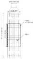
도 1 은 타입 1 무선 프레임의 구조를 나타내는 도면이다. 하향링크 무선 프레임(radio frame)은 10 개의 서브프레임(subframe)으로 구성되고, 하나의 서브프레임은 시간 영역(time domain)에서 2 개의 슬롯(slot)으로 구성된다. 하나의 서브프레임이 전송되는 데 걸리는 시간을 TTI(transmission time interval)이라 하고, 예를 들어 하나의 서브프레임의 길이는 1ms 이고, 하나의 슬롯의 길이는 0.5ms 일 수 있다. 하나의 슬롯은 시간 영역에서 복수의 OFDM 심볼을 포함하고, 주파수 영역에서 다수의 자원블록(Resource Block; RB)을 포함한다. 3GPP LTE 시스템에서는 하향링크에서 OFDMA 를 사용하므로, OFDM 심볼이 하나의 심볼 구간을 나타낸다. OFDM 심볼은 또한 SC-FDMA 심볼 또는 심볼 구간으로 칭하여질 수도 있다. 자원 블록(Resource Block; RB)은 자원 할당 단위이고, 하나의 슬롯에서 복수개의 연속적인 부반송파(subcarrier)를 포함할 수 있다.1 is a diagram showing the structure of a
하나의 슬롯에 포함되는 OFDM 심볼의 수는 CP(Cyclic Prefix)의 구성(configuration)에 따라 달라질 수 있다. CP 에는 확장된 CP(extended CP)와 일반 CP(normal CP)가 있다. 예를 들어, OFDM 심볼이 일반 CP 에 의해 구성된 경우, 하나의 슬롯에 포함되는 OFDM 심볼의 수는 7개일 수 있다. OFDM 심볼이 확장된 CP 에 의해 구성된 경우, 한 OFDM 심볼의 길이가 늘어나므로, 한 슬롯에 포함되는 OFDM 심볼의 수는 일반 CP 인 경우보다 적다. 확장된 CP 의 경우에, 예를 들어, 하나의 슬롯에 포함되는 OFDM 심볼의 수는 6 개일 수 있다. 단말이 빠른 속도로 이동하는 등의 경우와 같이 채널상태가 불안정한 경우, 심볼간 간섭을 더욱 줄이기 위해 확장된 CP 가 사용될 수 있다.The number of OFDM symbols included in one slot may vary according to the configuration of a CP (Cyclic Prefix). The CP has an extended CP and a normal CP. For example, when an OFDM symbol is configured by a general CP, the number of OFDM symbols included in one slot may be seven. When the OFDM symbol is configured by an extended CP, since the length of one OFDM symbol is increased, the number of OFDM symbols included in one slot is smaller than that of a normal CP. In the case of the extended CP, for example, the number of OFDM symbols included in one slot may be six. If the channel condition is unstable, such as when the UE moves at a high speed, an extended CP may be used to further reduce inter-symbol interference.
일반 CP 가 사용되는 경우 하나의 슬롯은 7 개의 OFDM 심볼을 포함하므로, 하나의 서브프레임은 14 개의 OFDM 심볼을 포함한다. 이때, 각 서브프레임의 처음 2 개 또는 3 개의 OFDM 심볼은 PDCCH(physical downlink control channel)에 할당되고, 나머지 OFDM 심볼은 PDSCH(physical downlink shared channel)에 할당될 수 있다.When a normal CP is used, one slot includes 7 OFDM symbols, and therefore one subframe includes 14 OFDM symbols. At this time, the first two or three OFDM symbols of each subframe may be allocated to a physical downlink control channel (PDCCH), and the remaining OFDM symbols may be allocated to a physical downlink shared channel (PDSCH).
무선 프레임의 구조는 예시에 불과하고, 무선 프레임에 포함되는 서브프레임의 수 또는 서브프레임에 포함되는 슬롯의 수, 슬롯에 포함되는 심볼의 수는 다양하게 변경될 수 있다.The structure of the radio frame is merely an example, and the number of subframes included in a radio frame, the number of slots included in a subframe, and the number of symbols included in a slot can be variously changed.
도 2 는 하나의 하향링크 슬롯에 대한 자원 그리드(resource grid)의 일례를 나타낸 예시도이다. 이는 OFDM 심볼이 일반 CP 로 구성된 경우이다. 도 2 를 참조하면, 하향링크 슬롯은 시간 영역에서 복수의 OFDM 심볼을 포함하고, 주파수 영역에서 다수의 자원블록을 포함한다. 여기서, 하나의 하향링크 슬롯은 7 OFDM 심볼을 포함하고, 하나의 자원블록은 12 부반송파를 포함하는 것을 예시적으로 기술하나, 이에 제한되는 것은 아니다. 자원 그리드 상의 각 요소(element)를 자원요소(RE)라 한다. 예를 들어, 자원 요소 a(k,l)은 k 번째 부반송파와 l 번째 OFDM 심볼에 위치한 자원 요소가 된다. 일반 CP 의 경우에, 하나의 자원블록은 12×7 자원요소를 포함한다 (확장된 CP 의 경우에는 12×6 자원요소를 포함한다). 각 부반송파의 간격은 15kHz 이므로, 하나의 자원블록은 주파수영역에서 약 180kHz 을 포함한다. NDL 은 하향링크 슬롯에 포함되는 자원블록의 수이다. NDL 의 값은 기지국의 스케줄링에 의해 설정되는 하향링크 전송 대역폭(bandwidth)에 따라 결정될 수 있다.2 is an exemplary diagram illustrating an example of a resource grid for one downlink slot. This is the case where the OFDM symbol is composed of a general CP. Referring to FIG. 2, a downlink slot includes a plurality of OFDM symbols in a time domain and a plurality of resource blocks in a frequency domain. Herein, one downlink slot includes 7 OFDM symbols, and one resource block includes 12 subcarriers by way of example, but the present invention is not limited thereto. Each element on the resource grid is called a resource element (RE). For example, the resource element a (k, l) is a resource element located in the kth subcarrier and the lth OFDM symbol. In the case of a generic CP, one resource block contains 12 × 7 resource elements (including 12 × 6 resource elements in the case of an extended CP). Since the interval of each subcarrier is 15 kHz, one resource block includes about 180 kHz in the frequency domain. The NDL is the number of resource blocks included in the downlink slot. The value of the NDL may be determined according to the downlink transmission bandwidth set by the scheduling of the base station.
도 3 은 하향링크 서브프레임의 구조를 나타내는 도면이다. 하나의 서브프레임 내에서 첫 번째 슬롯의 앞 부분의 최대 3 개의 OFDM 심볼은 제어 채널이 할당되는 제어 영역에 해당한다. 나머지 OFDM 심볼들은 물리하향링크공유채널(Physical Downlink Shared Chancel; PDSCH)이 할당되는 데이터 영역에 해당한다. 전송의 기본 단위는 하나의 서브프레임이 된다. 즉, 2 개의 슬롯에 걸쳐 PDCCH 및 PDSCH 가 할당된다. 3GPP LTE 시스템에서 사용되는 하향링크 제어 채널들에는, 예를 들어, 물리제어포맷지시자채널(Physical Control Format Indicator Channel; PCFICH), 물리하향링크제어채널(Physical Downlink Control Channel; PDCCH), 물리 HARQ 지시자채널(Physical Hybrid automatic repeat request Indicator Channel; PHICH) 등이 있다. PCFICH 는 서브프레임의 첫 번째 OFDM 심볼에서 전송되고 서브프레임 내의 제어 채널 전송에 사용되는 OFDM 심볼의 개수에 대한 정보를 포함한다. PHICH 는 상향링크 전송의 응답으로서 HARQ ACK/NACK 신호를 포함한다. PDCCH 를 통하여 전송되는 제어 정보를 하향링크 제어정보(Downlink Control Information; DCI)라 한다. DCI 는 상향링크 또는 하향링크 스케줄링 정보를 포함하거나 임의의 단말 그룹에 대한 상향링크 전송 전력 제어 명령을 포함한다. PDCCH 는 하향링크공유채널(DL-SCH)의 자원 할당 및 전송 포맷, 상향링크공유채널(UL-SCH)의 자원 할당 정보, 페이징채널(PCH)의 페이징 정보, DL-SCH 상의 시스템 정보, PDSCH 상으로 전송되는 임의접속응답(Random Access Response)과 같은 상위계층 제어 메시지의 자원 할당, 임의의 단말 그룹 내의 개별 단말에 대한 전송 전력 제어 명령의 세트, 전송 전력 제어 정보, VoIP(Voice over IP)의 활성화 등을 포함할 수 있다. 복수의 PDCCH 가 제어 영역 내에서 전송될 수 있다. 단말은 복수의 PDCCH 를 모니터링할 수 있다. PDCCH 는 하나 이상의 연속하는 제어채널요소(Control Channel Element; CCE)의 조합으로 전송된다. CCE 는 무선 채널의 상태에 기초한 코딩 레이트로 PDCCH 를 제공하기 위해 사용되는 논리 할당 단위이다. CCE 는 복수개의 자원 요소 그룹에 대응한다. PDCCH 의 포맷과 이용가능한 비트 수는 CCE 의 개수와 CCE 에 의해 제공되는 코딩 레이트 간의 상관관계에 따라서 결정된다. 기지국은 단말에게 전송되는 DCI 에 따라서 PDCCH 포맷을 결정하고, 제어 정보에 순환잉여검사(Cyclic Redundancy Check; CRC)를 부가한다. CRC 는 PDCCH 의 소유자 또는 용도에 따라 무선 네트워크 임시 식별자(Radio Network Temporary Identifier; RNTI)라 하는 식별자로 마스킹된다. PDCCH 가 특정 단말에 대한 것이면, 단말의 cell-RNTI(C-RNTI) 식별자가 CRC 에 마스킹될 수 있다. 또는, PDCCH 가 페이징 메시지에 대한 것이면, 페이징 지시자 식별자(Paging Indicator Identifier; P-RNTI)가 CRC 에 마스킹될 수 있다. PDCCH 가 시스템 정보(보다 구체적으로, 시스템 정보 블록(SIB))에 대한 것이면, 시스템 정보 식별자 및 시스템 정보 RNTI(SI-RNTI)가 CRC 에 마스킹될 수 있다. 단말의 임의 접속 프리앰블의 전송에 대한 응답인 임의접속응답을 나타내기 위해, 임의접속-RNTI(RA-RNTI)가 CRC 에 마스킹될 수 있다.3 is a diagram showing a structure of a downlink sub-frame. In a subframe, a maximum of three OFDM symbols in the first part of the first slot corresponds to a control area to which a control channel is allocated. The remaining OFDM symbols correspond to a data area to which a Physical Downlink Shared Chanel (PDSCH) is allocated. The basic unit of transmission is one subframe. That is, PDCCH and PDSCH are allocated over two slots. The downlink control channels used in the 3GPP LTE system include, for example, a physical control format indicator channel (PCFICH), a physical downlink control channel (PDCCH), a physical HARQ indicator channel (Physical Hybrid Automatic Repeat Request Indicator Channel (PHICH)). The PCFICH includes information on the number of OFDM symbols transmitted in the first OFDM symbol of the subframe and used for control channel transmission in the subframe. The PHICH includes an HARQ ACK / NACK signal as a response to the uplink transmission. The control information transmitted through the PDCCH is referred to as downlink control information (DCI). The DCI includes uplink or downlink scheduling information or includes an uplink transmission power control command for an arbitrary terminal group. The PDCCH includes a resource allocation and transmission format of a downlink shared channel (DL-SCH), resource allocation information of an uplink shared channel (UL-SCH), paging information of a paging channel (PCH), system information on a DL- A set of transmission power control commands for individual terminals in an arbitrary terminal group, transmission power control information, activation of VoIP (Voice over IP), resource allocation of upper layer control messages such as random access response And the like. A plurality of PDCCHs may be transmitted within the control domain. The UE can monitor a plurality of PDCCHs. The PDCCH is transmitted in a combination of one or more contiguous Control Channel Elements (CCEs). The CCE is a logical allocation unit used to provide the PDCCH with a coding rate based on the state of the wireless channel. The CCE corresponds to a plurality of resource element groups. The format of the PDCCH and the number of available bits are determined according to the correlation between the number of CCEs and the coding rate provided by the CCE. The base station determines the PDCCH format according to the DCI transmitted to the UE and adds a cyclic redundancy check (CRC) to the control information. The CRC is masked with an identifier called a Radio Network Temporary Identifier (RNTI) according to the owner or use of the PDCCH. If the PDCCH is for a particular UE, the cell-RNTI (C-RNTI) identifier of the UE may be masked in the CRC. Alternatively, if the PDCCH is for a paging message, a Paging Indicator Identifier (P-RNTI) may be masked in the CRC. If the PDCCH is for system information (more specifically, the System Information Block (SIB)), the system information identifier and the system information RNTI (SI-RNTI) may be masked to the CRC. A random access-RNTI (RA-RNTI) may be masked to the CRC to indicate a random access response that is a response to the transmission of the UE's random access preamble.
도 4 는 상향링크 서브프레임의 구조를 나타내는 도면이다. 상향링크 서브프레임은 주파수 영역에서 제어 영역과 데이터 영역으로 분할될 수 있다. 제어 영역에는 상향링크 제어 정보를 포함하는 물리상향링크제어채널(Physical Uplink Control Channel; PUCCH)이 할당된다. 데이터 영역에는 사용자 데이터를 포함하는 물리상향링크공유채널(Physical uplink shared channel; PUSCH)이 할당된다. 단일 반송파 특성을 유지하기 위해서, 하나의 단말은 PUCCH 와 PUSCH 를 동시에 전송하지 않는다. 하나의 단말에 대한 PUCCH 는 서브프레임에서 자원블록 쌍(RB pair)에 할당된다. 자원블록 쌍에 속하는 자원블록들은 2 슬롯에 대하여 상이한 부반송파를 차지한다. 이를 PUCCH 에 할당되는 자원블록 쌍이 슬롯 경계에서 주파수-호핑(frequency-hopped)된다고 한다.4 is a diagram illustrating the structure of an uplink subframe. The UL subframe may be divided into a control region and a data region in the frequency domain. A physical uplink control channel (PUCCH) including uplink control information is allocated to the control region. A physical uplink shared channel (PUSCH) including user data is allocated to the data area. To maintain a single carrier characteristic, one terminal does not transmit PUCCH and PUSCH at the same time. A PUCCH for one terminal is allocated to a resource block pair (RB pair) in a subframe. Resource blocks belonging to a resource block pair occupy different subcarriers for two slots. It is assumed that the resource block pair allocated to the PUCCH is frequency-hopped at the slot boundary.
다중안테나(MIMO) 시스템의 모델링Modeling of Multi-antenna (MIMO) Systems
MIMO((Multiple Input Multiple Output) 시스템은 다중 송신 안테나와 다중 수신 안테나를 사용하여 데이터의 송수신 효율을 향상시키는 시스템이다. MIMO 기술은 전체 메시지를 수신하기 위해 단일 안테나 경로에 의존하지 않고, 복수개의 안테나를 통해 수신되는 복수개의 데이터 조각들을 조합하여 전체 데이터를 수신할 수 있다.A MIMO (Multiple Input Multiple Output) system is a system that improves the transmission / reception efficiency of data using multiple transmit antennas and multiple receive antennas. The MIMO technique does not rely on a single antenna path to receive the entire message, And can receive the entire data.
MIMO 기술에는 공간 다이버시티(Spatial diversity) 기법과 공간 다중화(Spatial multiplexing) 기법 등이 있다. 공간 다이버시티 기법은 다이버시티 이득(gain)을 통해 전송 신뢰도(reliability)를 높이거나 셀 반경을 넓힐 수 있어, 고속으로 이동하는 단말에 대한 데이터 전송에 적합하다. 공간 다중화 기법은 서로 다른 데이터를 동시에 전송함으로써 시스템의 대역폭을 증가시키지 않고 데이터 전송률을 증가시킬 수 있다.The MIMO technique includes a spatial diversity technique and a spatial multiplexing technique. The spatial diversity scheme can increase transmission reliability or diversity gain through diversity gain and is suitable for data transmission to a terminal moving at a high speed. Spatial multiplexing can increase the data rate without increasing the bandwidth of the system by transmitting different data at the same time.
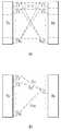
도 5 는 다중안테나를 갖는 무선 통신 시스템의 구성도이다. 도 5(a)에 도시된 바와 같이 송신 안테나의 수를 NT 개로, 수신 안테나의 수를 NR 개로 늘리면, 송신기나 수신기에서만 다수의 안테나를 사용하게 되는 경우와 달리 안테나 수에 비례하여 이론적인 채널 전송 용량이 증가한다. 따라서, 전송 레이트를 향상시키고 주파수 효율을 획기적으로 향상시킬 수 있다. 채널 전송 용량이 증가함에 따라, 전송 레이트는 이론적으로 단일 안테나 이용시의 최대 전송 레이트(Ro)에 레이트 증가율(Ri)이 곱해진 만큼 증가할 수 있다.5 is a configuration diagram of a wireless communication system having multiple antennas. As shown in FIG. 5A, when the number of transmission antennas is increased to NT and the number of reception antennas is increased to NR, unlike the case where a plurality of antennas are used only in a transmitter and a receiver, a theoretical channel transmission Capacity increases. Therefore, the transmission rate can be improved and the frequency efficiency can be remarkably improved. As the channel transmission capacity increases, the transmission rate can theoretically increase by the rate of rate increase Ri multiplied by the maximum transmission rate Ro in single antenna use.

예를 들어, 4 개의 송신 안테나와 4 개의 수신 안테나를 이용하는 MIMO 통신 시스템에서는 단일 안테나 시스템에 비해 이론상 4 배의 전송 레이트를 획득할 수 있다. 다중안테나 시스템의 이론적 용량 증가가 90 년대 중반에 증명된 이후 이를 실질적인 데이터 전송률 향상으로 이끌어 내기 위한 다양한 기술들이 현재까지 활발히 연구되고 있다. 또한, 몇몇 기술들은 이미 3 세대 이동 통신과 차세대 무선랜 등의 다양한 무선 통신의 표준에 반영되고 있다.For example, in a MIMO communication system using four transmit antennas and four receive antennas, it is possible to obtain a transmission rate four times higher than the single antenna system. After the theoretical capacity increase of the multi-antenna system has been proved in the mid-90s, various techniques have been actively researched to bring it up to practical data rate improvement. In addition, several technologies have already been reflected in various wireless communication standards such as 3G mobile communication and next generation wireless LAN.
현재까지의 다중안테나 관련 연구 동향을 살펴보면 다양한 채널 환경 및 다중접속 환경에서의 다중안테나 통신 용량 계산 등과 관련된 정보 이론 측면 연구, 다중안테나 시스템의 무선 채널 측정 및 모형 도출 연구, 전송 신뢰도 향상 및 전송률 향상을 위한 시공간 신호 처리 기술 연구 등 다양한 관점에서 활발히 연구가 진행되고 있다.The research trends related to multi-antenna up to now include information theory study related to calculation of multi-antenna communication capacity in various channel environment and multiple access environment, study of wireless channel measurement and modeling of multi-antenna system, improvement of transmission reliability and improvement of transmission rate And research on space-time signal processing technology.
다중안테나 시스템에서의 통신 방법을 수학적 모델링을 이용하여 보다 구체적으로 설명한다. 상기 시스템에는 NT 개의 송신 안테나와 NR 개의 수신 안테나가 존재한다고 가정한다.A communication method in a multi-antenna system will be described in more detail using mathematical modeling. It is assumed that there are NT transmit antennas and NR receive antennas in the system.
송신 신호를 살펴보면, NT 개의 송신 안테나가 있는 경우 전송 가능한 최대 정보는 NT 개이다. 전송 정보는 다음과 같이 표현될 수 있다.Looking at the transmitted signal, if there are NT transmit antennas, the maximum transmittable information is NT. The transmission information can be expressed as follows.

각각의 전송 정보


또한,

전송전력이 조정된 정보 벡터(information vector)


여기에서,wij는 i 번째 송신 안테나와 j 번째 정보간의 가중치를 의미한다. W는 프리코딩 행렬이라고도 불린다.Here,wij denotes a weight between the i-th transmit antenna and the j-th information. W is also referred to as a precoding matrix.
한편, 송신신호 x 는 2 가지 경우(예를 들어, 공간 다이버시티 및 공간 다중화)에 따라 다른 방법으로 고려될 수 있다. 공간 다중화의 경우, 상이한 신호가 다중화되고 다중화된 신호가 수신측으로 전송되어, 정보 벡터(들)의 요소(element)가 상이한 값을 가진다. 한편, 공간 다이버시티의 경우에는, 동일한 신호가 복수개의 채널 경로를 통하여 반복적으로 전송되어, 정보 벡터(들)의 요소가 동일한 값을 가진다. 물론, 공간 다중화 및 공간 다이버시티 기법의 조합 역시 고려할 수 있다. 즉, 동일한 신호가 예를 들어 3 개의 전송 안테나를 통해 공간 다이버시티 기법에 따라 전송되고, 나머지 신호들은 공간 다중화되어 수신측으로 전송될 수도 있다.On the other hand, the transmission signal x can be considered in different ways depending on two cases (for example, spatial diversity and spatial multiplexing). In the case of spatial multiplexing, different signals are multiplexed and the multiplexed signal is transmitted to the receiving side, so that the elements of the information vector (s) have different values. On the other hand, in the case of spatial diversity, the same signal is repeatedly transmitted through a plurality of channel paths, so that the elements of the information vector (s) have the same value. Of course, a combination of spatial multiplexing and spatial diversity techniques may also be considered. That is, the same signal may be transmitted according to a spatial diversity scheme, for example, through three transmission antennas, and the remaining signals may be spatially multiplexed and transmitted to the receiving side.
NR 개의 수신 안테나가 있는 경우 각 안테나의 수신신호

다중안테나 무선 통신 시스템에서 채널을 모델링하는 경우, 채널은 송수신 안테나 인덱스에 따라 구분될 수 있다. 송신 안테나 j 로부터 수신 안테나 i 를 거치는 채널을hij로 표시하기로 한다.hij에서, 인덱스의 순서가 수신 안테나 인덱스가 먼저, 송신 안테나의 인덱스가 나중임에 유의한다.When a channel is modeled in a multi-antenna wireless communication system, the channel may be classified according to the transmission / reception antenna index. And the channel through the reception antenna i from the transmission antenna j is denoted byhij .In hij , note that the order of the index is the receive antenna index and the index of the transmit antenna.
도 5(b)에 NT 개의 송신 안테나에서 수신 안테나 i 로의 채널을 도시하였다. 상기 채널을 묶어서 벡터 및 행렬 형태로 표시할 수 있다. 도 5(b)에서, 총 NT 개의 송신 안테나로부터 수신 안테나 i 로 도착하는 채널은 다음과 같이 나타낼 수 있다.FIG. 5 (b) shows a channel from NT transmit antennas to receive antennas i. The channels can be grouped and displayed in vector and matrix form. In FIG. 5 (b), a channel arriving from a total of NT transmit antennas to receive antennas i may be expressed as follows.

따라서, NT 개의 송신 안테나로부터 NR 개의 수신 안테나로 도착하는 모든 채널은 다음과 같이 표현될 수 있다.Therefore, all channels arriving from the NT transmit antennas to the NR receive antennas can be expressed as:

실제 채널에는 채널 행렬 H를 거친 후에 백색잡음(AWGN; Additive White Gaussian Noise)이 더해진다. NR 개의 수신 안테나 각각에 더해지는 백색잡음

상술한 수식 모델링을 통해 수신신호는 다음과 같이 표현될 수 있다.Through the above-described equation modeling, the received signal can be expressed as follows.

채널 상태를 나타내는 채널 행렬 H의 행과 열의 수는 송수신 안테나의 수에 의해 결정된다. 채널 행렬 H에서 행의 수는 수신 안테나의 수 NR 과 같고, 열의 수는 송신 안테나의 수 NT 와 같다. 즉, 채널 행렬 H는 행렬이 NR×NT 된다.The number of rows and columns of the channel matrix H representing the channel state is determined by the number of transmitting and receiving antennas. The number of rows in channel matrix H equals the number of receive antennas NR, and the number of columns equals the number NT of transmit antennas. That is, the channel matrix H is NR × NT.
행렬의 랭크(rank)는 서로 독립인(independent) 행 또는 열의 개수 중에서 최소 개수로 정의된다. 따라서, 행렬의 랭크는 행 또는 열의 개수 보다 클 수 없다. 채널 행렬 H의 랭크(rank(H))는 다음과 같이 제한된다.The rank of a matrix is defined as the minimum number of independent rows or columns. Thus, the rank of the matrix can not be greater than the number of rows or columns. The rank (rank (H)) of the channel matrix H is limited as follows.

MIMO 전송에 있어서 '랭크(Rank)' 는 독립적으로 신호를 전송할 수 있는 경로의 수를 나타내며, '레이어(layer)의 개수' 는 각 경로를 통해 전송되는 신호 스트림의 개수를 나타낸다. 일반적으로 송신단은 신호 전송에 이용되는 랭크 수에 대응하는 개수의 레이어를 전송하기 때문에 특별한 언급이 없는 한 랭크는 레이어 개수와 동일한 의미를 가진다.In MIMO transmission, 'rank' represents the number of paths that can independently transmit signals, and 'number of layers' represents the number of signal streams transmitted through each path. In general, since the transmitting end transmits a number of layers corresponding to the number of ranks used for signal transmission, the rank has the same meaning as the number of layers unless otherwise specified.
참조 신호 (Reference Signal; RS)A reference signal (RS)
무선 통신 시스템에서 패킷을 전송할 때, 전송되는 패킷은 무선 채널을 통해서 전송되기 때문에 전송과정에서 신호의 왜곡이 발생할 수 있다. 왜곡된 신호를 수신측에서 올바로 수신하기 위해서는 채널 정보를 이용하여 수신 신호에서 왜곡을 보정하여야 한다. 채널 정보를 알아내기 위해서, 송신측과 수신측에서 모두 알고 있는 신호를 전송하여, 상기 신호가 채널을 통해 수신될 때의 왜곡 정도를 가지고 채널 정보를 알아내는 방법을 주로 사용한다. 상기 신호를 파일럿 신호 (Pilot Signal) 또는 참조 신호 (Reference Signal)라고 한다.When a packet is transmitted in a wireless communication system, since the transmitted packet is transmitted through a wireless channel, signal distortion may occur in the transmission process. In order to properly receive the distorted signal at the receiving side, the distortion should be corrected in the received signal using the channel information. In order to determine the channel information, a method is used in which a signal known to both the transmitting side and the receiving side is transmitted, and channel information is detected with a degree of distortion when the signal is received through the channel. The signal is referred to as a pilot signal or a reference signal.
다중안테나를 사용하여 데이터를 송수신하는 경우에는 각 송신 안테나와 수신 안테나 사이의 채널 상황을 알아야 올바른 신호를 수신할 수 있다. 따라서, 각 송신 안테나 별로 별도의 참조 신호가 존재하여야 한다.When transmitting and receiving data using multiple antennas, it is necessary to know the channel condition between each transmitting antenna and the receiving antenna so that a correct signal can be received. Therefore, there is a separate reference signal for each transmission antenna.
이동 통신 시스템에서 참조신호(RS)는 그 목적에 따라 크게 두 가지로 구분될 수 있다. 하나는 채널 정보 획득을 위해 사용되는 RS 이고, 다른 하나는 데이터 복조를 위해 사용되는 RS 이다. 전자는 단말이 하향 링크 채널 정보를 획득하도록 하기 위한 RS 이므로 광대역으로 전송되어야 하고, 특정 서브프레임에서 하향링크 데이터를 수신하지 않는 단말이라도 해당 RS 를 수신하고 측정할 수 있어야 한다. 이러한 RS 는 핸드 오버 등을 위한 측정 등을 위해서도 사용된다. 후자는 기지국이 하향링크를 보낼 때 해당 자원에 함께 보내는 RS 로서, 단말은 해당 RS 를 수신함으로써 채널 추정을 할 수 있고, 따라서 데이터를 복조할 수 있게 된다. 이러한 RS 는 데이터가 전송되는 영역에 전송되어야 한다.In the mobile communication system, the reference signal RS can be roughly classified into two types according to its purpose. One is an RS used for channel information acquisition and the other is an RS used for data demodulation. Since the former is an RS for allowing the UE to acquire downlink channel information, it should be transmitted in a wide band, and even a terminal not receiving downlink data in a specific subframe must be able to receive and measure the corresponding RS. These RSs are also used for measurements for handover and the like. The latter is an RS transmitted together with a corresponding resource when the BS transmits the downlink, and the UE can perform channel estimation by receiving the corresponding RS, and thus can demodulate the data. These RSs must be transmitted in the area where data is transmitted.
기존의 3GPP LTE(예를 들어, 3GPP LTE 릴리즈-8) 시스템에서는 유니캐스트(unicast) 서비스를 위해서 2 가지 종류의 하향링크 RS 를 정의한다. 그 중 하나는 공용 참조신호(Common RS; CRS)이고, 다른 하나는 전용 참조신호(Dedicated RS; DRS)이다. CRS 는 채널 상태에 대한 정보 획득 및 핸드오버 등을 위한 측정 등을 위해서 사용되고, 셀-특정(cell-specific) RS 라고 칭할 수도 있다. DRS 는 데이터 복조를 위해 사용되고, 단말-특정(UE-specific) RS 라고 칭할 수도 있다. 기존의 3GPP LTE 시스템에서 DRS 는 데이터 복조용으로만 사용되며 CRS 는 채널 정보 획득 및 데이터 복조의 두 가지 목적으로 다 사용될 수 있다.In the existing 3GPP LTE (e.g., 3GPP LTE Release-8) system, two kinds of downlink RSs are defined for a unicast service. One of them is a common RS (CRS), and the other is a dedicated RS (DRS). The CRS is used for acquiring information on the channel status and for measuring for handover, etc., and may also be referred to as a cell-specific RS. The DRS is used for data demodulation and may also be referred to as a UE-specific RS. In the existing 3GPP LTE system, DRS is used only for data demodulation and CRS can be used for both channel information acquisition and data demodulation.
CRS 는 셀-특정으로 전송되는 RS 이며, 광대역(wideband)에 대해서 매 서브프레임마다 전송된다. CRS 는 기지국의 전송 안테나 개수에 따라서 최대 4 개의 안테나 포트에 대해서 전송될 수 있다. 예를 들어 기지국의 송신 안테나의 개수가 두 개일 경우, 0 번과 1 번 안테나 포트에 대한 CRS 가 전송되고, 네 개인 경우 0~3 번 안테나 포트에 대한 CRS 가 각각 전송된다.CRS is an RS transmitted in a cell-specific manner, and is transmitted in every subframe for a wideband. The CRS can be transmitted for up to four antenna ports, depending on the number of transmit antennas of the base station. For example, if the number of transmit antennas of the base station is two, the CRS is transmitted for the
도 6 은 기지국이 4 개의 전송 안테나를 지원하는 시스템에서 하나의 자원블록 (일반 CP 의 경우, 시간 상으로 14 개의 OFDM 심볼 × 주파수 상으로 12 부반송파) 상에서 CRS 및 DRS 의 패턴을 나타내는 도면이다. 도 6 에서 'R0', 'R1', 'R2' 및 'R3' 로 표시된 자원 요소(RE)는, 각각 안테나 포트 인덱스 0, 1, 2 및 3 에 대한 CRS 의 위치를 나타낸다. 한편, 도 6 에서 'D'로 표시된 자원 요소는 LTE 시스템에서 정의되는 DRS 의 위치를 나타낸다.6 is a diagram showing a pattern of CRS and DRS on one resource block (14 OFDM symbols in time × 12 subcarriers on frequency in a normal CP) in a system in which a base station supports four transmit antennas. In FIG. 6, the resource elements RE denoted by 'R0', 'R1', 'R2' and 'R3' represent the positions of the CRSs for the
LTE 시스템의 진화 발전된 형태의 LTE-A 시스템에서는, 하향링크에서 최대 8 개의 송신 안테나를 지원할 수 있다. 따라서, 최대 8 개 송신 안테나에 대한 RS 역시 지원되어야 한다. LTE 시스템에서의 하향링크 RS 는 최대 4 개의 안테나 포트에 대해서만 정의되어 있으므로, LTE-A 시스템에서 기지국이 4 개 이상 최대 8 개의 하향 링크 송신 안테나를 가질 경우 이들 안테나 포트들에 대한 RS 가 추가적으로 정의되어야 한다. 최대 8 개의 송신 안테나 포트에 대한 RS 로서, 채널 측정을 위한 RS 와 데이터 복조를 위한 RS 두 가지가 모두 고려되어야 한다.Evolution of LTE System In the advanced type of LTE-A system, up to 8 transmit antennas can be supported in the downlink. Therefore, RS for up to 8 transmit antennas must also be supported. Since the downlink RS in the LTE system is defined only for a maximum of four antenna ports, if the base station has more than four downlink transmission antennas in the LTE-A system, RSs for the antenna ports are additionally defined do. As RSs for up to eight transmit antenna ports, both RS for channel measurement and RS for data demodulation must be considered.
LTE-A 시스템을 설계함에 있어서 중요한 고려 사항 중 하나는 역방향 호환성(backward compatibility)이다. 역방향 호환성이란, 기존의 LTE 단말이 LTE-A 시스템에서도 올바르게 동작하도록 지원하는 것을 의미한다. RS 전송 관점에서 보았을 때, LTE 표준에서 정의되어 있는 CRS 가 전 대역으로 매 서브프레임마다 전송되는 시간-주파수 영역에 최대 8 개의 송신 안테나 포트에 대한 RS 를 추가하는 경우, RS 오버헤드가 지나치게 커지게 된다. 따라서, 최대 8 안테나 포트에 대한 RS 를 새롭게 설계함에 있어서 RS 오버헤드를 줄이는 것이 고려되어야 한다.One of the important considerations in designing an LTE-A system is backward compatibility. Backward compatibility means that existing LTE terminals support proper operation in the LTE-A system. From the viewpoint of RS transmission, when RSs for up to 8 transmit antenna ports are added to the time-frequency domain in which the CRS defined in the LTE standard is transmitted for every subframe in all bands, RS overhead is excessively large do. Therefore, reducing the RS overhead in the new RS design for up to 8 antenna ports should be considered.
LTE-A 시스템에서 새롭게 도입되는 RS 는 크게 2 가지로 분류할 수 있다. 그 중 하나는 전송 랭크, 변조및코딩기법(Modulation and Coding Scheme; MCS), 프리코딩 행렬인덱스(Precoding Matrix Index; PMI) 등의 선택을 위한 채널 측정 목적의 RS 인 채널상태정보-참조신호(Channel State Information RS; CSI-RS)이고, 다른 하나는 최대 8 개의 전송 안테나를 통해 전송되는 데이터를 복조하기 위한 목적의 RS 인 복조-참조신호(DeModulation RS; DM RS)이다.The RSs newly introduced in the LTE-A system can be roughly classified into two types. One of them is a channel status information-reference signal (RS), which is an RS for channel measurement for selection of a transmission rank, a modulation and coding scheme (MCS), a precoding matrix index (PMI) The other is a demodulation RS (DM RS), which is a RS for demodulating data transmitted through up to 8 transmit antennas.
채널 측정 목적의 CSI-RS 는, 기존의 LTE 시스템에서의 CRS 가 채널 측정, 핸드오버 등의 측정 등의 목적과 동시에 데이터 복조를 위해 사용되는 것과 달리, 채널 측정 위주의 목적을 위해서 설계되는 특징이 있다. 물론 CSI-RS 역시 핸드오버 등의 측정 등의 목적으로도 사용될 수도 있다. CSI-RS 가 채널 상태에 대한 정보를 얻는 목적으로만 전송되므로, 기존의 LTE 시스템에서의 CRS 와 달리, 매 서브프레임마다 전송되지 않아도 된다. 따라서, CSI-RS 의 오버헤드를 줄이기 위하여 CSI-RS 는 시간 축 상에서 간헐적으로(예를 들어, 주기적으로) 전송되도록 설계될 수 있다.The CSI-RS for channel measurement purposes is different from the CRS in the existing LTE system, which is used for data demodulation in addition to the purpose of channel measurement, handover, etc., have. Of course, the CSI-RS may also be used for measurement such as handover. Since the CSI-RS is transmitted only for the purpose of obtaining information on the channel status, unlike the CRS in the existing LTE system, it is not transmitted every subframe. Therefore, in order to reduce the overhead of the CSI-RS, the CSI-RS can be designed to be transmitted intermittently (e.g., periodically) on the time axis.
만약 어떤 하향링크 서브프레임 상에서 데이터가 전송되는 경우에는, 데이터 전송이 스케줄링된 단말에게 전용으로(dedicated) DM RS 가 전송된다. 특정 단말 전용의 DM RS 는, 해당 단말이 스케줄링된 자원영역, 즉 해당 단말에 대한 데이터가 전송되는 시간-주파수 영역에서만 전송되도록 설계될 수 있다.If data is transmitted on a downlink subframe, a dedicated DM RS is transmitted to the scheduled UE for data transmission. The DM RS dedicated to a specific terminal can be designed to be transmitted only in a resource region in which the terminal is scheduled, that is, in a time-frequency region in which data for the terminal is transmitted.
도 7 은 LTE-A 시스템에서 정의되는 DM RS 패턴의 일례를 나타내는 도면이다. 도 7 에서는 하향링크 데이터가 전송되는 하나의 자원블록(일반 CP 의 경우, 시간 상으로 14 개의 OFDM 심볼 × 주파수 상으로 12 부반송파) 상에서 DM RS 가 전송되는 자원요소의 위치를 나타낸다. DM RS 는 LTE-A 시스템에서 추가적으로 정의되는 4 개의 안테나 포트(안테나 포트 인덱스 7, 8, 9 및 10)에 대하여 전송될 수 있다. 서로 다른 안테나 포트에 대한 DM RS 는 상이한 주파수 자원(부반송파) 및/또는 상이한 시간 자원(OFDM 심볼)에 위치하는 것으로 구분될 수 있다(즉, FDM 및/또는 TDM 방식으로 다중화될 수 있다). 또한, 동일한 시간-주파수 자원 상에 위치하는 서로 다른 안테나 포트에 대한 DM RS 들은 서로 직교 코드(orthogonal code)에 의해서 구분될 수 있다(즉, CDM 방식으로 다중화될 수 있다). 도 7 의 예시에서 DM RS CDM 그룹 1 로 표시된 자원요소(RE) 들에는 안테나 포트 7 및 8 에 대한 DM RS 들이 위치할 수 있고, 이들은 직교 코드에 의해 다중화될 수 있다. 마찬가지로, 도 7 의 예시에서 DM RS 그룹 2 로 표시된 자원요소들에는 안테나 포트 9 및 10 에 대한 DM RS 들이 위치할 수 있고, 이들은 직교 코드에 의해 다중화될 수 있다.7 is a diagram showing an example of a DM RS pattern defined in the LTE-A system. 7 shows a location of a resource element in which a DM RS is transmitted on one resource block in which downlink data is transmitted (in the case of a general CP, 14 OFDM symbols in time × 12 subcarriers on frequency). The DM RS may be transmitted for four antenna ports (
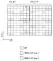
도 8 은 LTE-A 시스템에서 정의되는 CSI-RS 패턴의 예시들을 나타내는 도면이다. 도 8 에서는 하향링크 데이터가 전송되는 하나의 자원블록(일반 CP 의 경우, 시간 상으로 14 개의 OFDM 심볼 × 주파수 상으로 12 부반송파) 상에서 CSI-RS 가 전송되는 자원요소의 위치를 나타낸다. 어떤 하향링크 서브프레임에서 도 8(a) 내지 8(e) 중 하나의 CSI-RS 패턴이 이용될 수 있다. CSI-RS 는 LTE-A 시스템에서 추가적으로 정의되는 8 개의 안테나 포트(안테나 포트 인덱스 15, 16, 17, 18, 19, 20, 21 및 22) 에 대하여 전송될 수 있다. 서로 다른 안테나 포트에 대한 CSI-RS 는 상이한 주파수 자원(부반송파) 및/또는 상이한 시간 자원(OFDM 심볼)에 위치하는 것으로 구분될 수 있다(즉, FDM 및/또는 TDM 방식으로 다중화될 수 있다). 또한, 동일한 시간-주파수 자원 상에 위치하는 서로 다른 안테나 포트에 대한 CSI-RS 들은 서로 직교 코드(orthogonal code)에 의해서 구분될 수 있다(즉, CDM 방식으로 다중화될 수 있다). 도 8(a) 의 예시에서 CSI-RS CDM 그룹 1 로 표시된 자원요소(RE) 들에는 안테나 포트 15 및 16 에 대한 CSI-RS 들이 위치할 수 있고, 이들은 직교 코드에 의해 다중화될 수 있다. 도 8(a) 의 예시에서 CSI-RS CDM 그룹 2 로 표시된 자원요소들에는 안테나 포트 17 및 18 에 대한 CSI-RS 들이 위치할 수 있고, 이들은 직교 코드에 의해 다중화될 수 있다. 도 8(a) 의 예시에서 CSI-RS CDM 그룹 3 으로 표시된 자원요소들에는 안테나 포트 19 및 20 에 대한 CSI-RS 들이 위치할 수 있고, 이들은 직교 코드에 의해 다중화될 수 있다. 도 8(a) 의 예시에서 CSI-RS CDM 그룹 4 로 표시된 자원요소들에는 안테나 포트 21 및 22 에 대한 CSI-RS 들이 위치할 수 있고, 이들은 직교 코드에 의해 다중화될 수 있다. 도 8(a)를 기준으로 설명한 동일한 원리가 도 8(b) 내지 8(e)에 적용될 수 있다.8 is a diagram showing examples of CSI-RS patterns defined in the LTE-A system. 8 shows a location of a resource element to which a CSI-RS is transmitted on one resource block in which downlink data is transmitted (in the case of a general CP, 14 OFDM symbols in time × 12 subcarriers in frequency). In some downlink subframes, the CSI-RS pattern of one of Figs. 8 (a) to 8 (e) can be used. The CSI-RS may be transmitted for eight antenna ports (
도 9 는 LTE-A 시스템에서 정의되는 ZP(Zero Power) CSI-RS 패턴의 예시를 나타내는 도면이다. ZP CSI-RS 의 용도는 크게 두 가지로 분리된다. 첫 번째로 CSI-RS 성능 개선을 위한 용도로 사용된다. 즉, 한 네트워크는 다른 네트워크의 CSI-RS 측정 성능을 개선하기 위해 다른 네트워크의 CSI-RS RE 에 뮤팅(muting)을 하고 자신의 UE 가 올바르게 레이트 매칭(rate matching)을 수행할 수 있도록 뮤팅된 RE 를 ZP CSI-RS 로 설정하여 알려 줄 수 있다. 두 번째로 CoMP CQI 계산을 위한 간섭 측정의 용도로 사용된다. 즉 ZP CRS-RS RE 에 일부 네트워크가 뮤팅을 수행하고 UE 는 이 ZP CSI-RS 로부터 간섭을 측정하여 CoMP CQI 를 계산할 수 있다.9 is a diagram illustrating an example of a Zero Power CSI-RS pattern defined in the LTE-A system. The use of ZP CSI-RS is largely divided into two. First, it is used to improve CSI-RS performance. That is, one network may mutate the CSI-RS RE of another network to improve the CSI-RS measurement performance of another network, and may perform a muting RE Can be set as ZP CSI-RS. Secondly, it is used for interference measurement to calculate CoMP CQI. That is, some networks perform muting in the ZP CRS-RS RE and the UE can calculate the CoMP CQI by measuring the interference from this ZP CSI-RS.
도 6 내지 9 의 RS 패턴들은 단지 예시적인 것이며, 본 발명의 다양한 실시예들을 적용함에 있어서 특정 RS 패턴에 한정되는 것이 아니다. 즉, 도 6 내지 9 와 다른 RS 패턴이 정의 및 사용되는 경우에도 본 발명의 다양한 실시예들은 동일하게 적용될 수 있다.The RS patterns in Figures 6-9 are exemplary only and are not limited to a particular RS pattern in applying various embodiments of the present invention. That is, various embodiments of the present invention can be equally applied even when RS patterns different from those of FIGS. 6 to 9 are defined and used.
ABS(Almost Blank Subframe)ABS (Almost Blank Subframe)
이하에서는 시간 영역(Time Domain)에서의 ICIC(Inter-Cell Interference Coordination) 및 ABS(Almost Blank Subframe)에 대하여 설명한다.Inter-Cell Interference Coordination (ICIC) and Almost Blank Subframe (ABS) in a time domain will be described below.
먼저, 시간 자원에 대한 ICIC 방식을 설명하면, 3GPP LTE-A (릴리즈-10) 시스템의 경우, 전체 시간 영역을 여러 개의 서브프레임으로 나누고 각 서브프레임에 대한 사일런싱(silencing) 또는 감소된 전송 전력 적용 여부를 지시(indicate) 할 수 있다. 시간 축에서의 ICIC 란, 서로 다른 셀들간에 서브 프레임에 대한 활용을 어떻게 할 것인지를 협력(coordination)하는 것을 의미한다. 이 때, 서브 프레임 활용에 대한 정보는 백홀 시그널링(backhaul signaling)이나 OAM (Operation Administration and Maintenance) 설정으로 이루어 지며, 이를 ABS 라고 한다.First, in the 3GPP LTE-A (Release-10) system, the total time domain is divided into a plurality of subframes, and a silencing or a reduced transmission power You can indicate whether to apply. ICIC on the time axis means coordinating how to use subframes between different cells. At this time, the information on the use of the subframe consists of backhaul signaling or operation administration and maintenance (OAM), which is called ABS.
도 10 은 ABS 가 적용되는 매크로 셀과 피코 셀의 환경을 예시한다. 도 10 의 (a)에서 가해(aggressor) 입장의 매크로 셀과 피해(victim) 입장의 피코 셀이 있을 때, 매크로 셀은 피코 셀이 강한 간섭을 받지 않을 수 있도록 특정 서브프레임을 보호할 수 있다. 또는, 도 10 의 (b)에서 가해(aggressor) 입장의 피코 셀과 피해(victim) 입장의 매크로 셀이 있을 때, 피코 셀은 매크로 셀이 강한 간섭을 받지 않을 수 있도록 특정 서브프레임을 보호할 수 있다. 즉, ABS 란 해당 서브프레임에서 전송 전력을 줄이거나 트래픽(traffic) 또는 활동성(activity)이 감소된 서브 프레임을 뜻한다. 또한, ABS 는 아무것도 전송되지 않는 서브 프레임을 포함한다.10 illustrates the environment of macro cells and picocells to which ABS is applied. In FIG. 10 (a), when there is an aggressor entry macro cell and a victim entry picocell, the macro cell can protect the specific subframe so that the picocell does not receive strong interference. Alternatively, in FIG. 10B, when there is a macro cell of an aggressor entry picocell and a victim entry, the picocell can protect the specific subframe so that the macrocell does not receive strong interference have. That is, ABS means a subframe in which the transmission power is reduced or the traffic or activity is reduced in the corresponding subframe. Also, the ABS includes a subframe in which nothing is transmitted.
ABS 를 위하여, eNB 간 통신에 사용되는 X2 인터페이스(interface)를 이용할 수 있다. ABS 를 잘 활용하기 위해서, eNB 는 UE 에게 제한 측정(restricted measurement)을 설정(configure)하고, 이를 위하여 ABS 에 기반한 서로 다른 두 가지의 측정 셋(measurement set)을 UE 에게 전송한다.For ABS, you can use the X2 interface, which is used for communication between eNBs. To make good use of ABS, the eNB configures restricted measurements to the UE and sends two different sets of measurements based on the ABS to the UE for this purpose.
즉, 이웃 셀, 특히 가해(aggressor) 셀의 ABS 패턴(pattern)을 X2 인터페이스로 수신한 eNB 는 해당 eNB 의 ABS 패턴에 기반하여 자신의 서빙 UE 에게 측정 셋을 설정한다. 종래의 3GPP LTE 시스템에서 MCS, RI 및 PMI 를 선택하기 위해서 UE 는 모든 서브 프레임에서 CRS 를 측정해야 한다. 하지만, 이웃 셀이 ABS 를 설정하여 가해 셀이 해당 서브 프레임에서 하향 링크 신호 전송을 전혀 하지 않거나 감소된 전력(reduced power)으로 하향 링크 신호를 전송하는 경우, 간섭(interference)이 ABS 패턴에 따라 달라지므로 UE 는 특정한 서브프레임에서 측정을 수행해야 한다.That is, an eNB receiving an ABS pattern of a neighboring cell, particularly an aggressor cell, with an X2 interface sets a measurement set to its serving UE based on the ABS pattern of the eNB. To select MCS, RI and PMI in a conventional 3GPP LTE system, the UE must measure the CRS in all subframes. However, when the neighboring cell sets the ABS and the impending cell does not transmit the downlink signal in the corresponding subframe at all or transmits the downlink signal with the reduced power, the interference depends on the ABS pattern. The UE must perform measurements in a specific subframe.
이를 위하여 eNB 가 특정 UE 에게 특정 서브프레임에 대한 측정 만을 수행하도록 지시하고 UE 가 특정 서브프레임에서 측정을 수행하는 경우, 이를 제한된 측정(restricted measurement)이라 칭한다.For this purpose, when the eNB instructs a specific UE to perform only a measurement on a specific subframe, and the UE performs measurement in a specific subframe, this is referred to as a restricted measurement.
제한된 측정을 위하여, 서브프레임 중 ABS 로 설정되는 일부 서브프레임에 대한 정보를 기지국 간 인터페이스로 전달해야 하는데, 예를 들면, 3GPP LTE-A 표준에서 규정하고 있는 ABS 정보(information)와 ABS 상태(status)를 들 수 있다.For limited measurement, information about some subframes set in the ABS among the subframes must be transmitted to the inter-base station interface. For example, the ABS information and the status (status) defined in the 3GPP LTE- ).
먼저, ABS 정보(information)는 ABS 로 사용할 서브프레임을 비트맵으로 나타내는 "ABS pattern info" 필드를 포함할 수 있다. "ABS 패턴 info" 필드는 FDD 에서는 40 비트, TDD 의 경우 UL-DL 설정에 따라 다르지만 최대 70 비트의 비트맵으로 구성될 수 있다. FDD 를 예로 들어 설명하면, 40 비트는 40 개의 서브 프레임을 나타내며, 비트 값이 1 이면 ABS 를, 0 이면 non-ABS 를 나타낼 수 있다. 제한된 측정을 UE 에게 설정할 때, CRS 측정을 위하여 해당 셀의 CRS 안테나 포트 개수를 알려준다. 또한, 측정 서브셋(Measurement Subset)은 제한된 측정을 설정하지 위한 일종의 추천 제한 측정 셋(recommended restricted measurement set)이다.First, the ABS information may include an "ABS pattern info" field indicating a subframe to be used as an ABS in a bit map. The "ABS pattern info" field may be composed of a bitmap of up to 70 bits, though it depends on the setting of 40 bits in FDD and UL-DL in case of TDD. FDD as an example, 40 bits represent 40 subframes, and a bit value of 1 indicates ABS, and a value of 0 indicates non-ABS. When a limited measurement is set to the UE, the number of CRS antenna ports of the corresponding cell is reported for CRS measurement. In addition, the Measurement Subset is a kind of recommended restricted measurement set for setting a limited measurement.
다음으로, ABS 상태(status) 정보는 eNB 가 ABS 패턴을 바꾸어야 하는지의 여부를 나타내는 정보이다. ABS 상태 정보에 포함된 "Usable ABS pattern Info" 는 "ABS Pattern Info" 의 서브셋으로, ABS 로 지정된 서브 프레임이 간섭 완화(interference mitigation)를 위한 목적으로 사용되었는지 아닌지의 여부를 나타낸다. 또한 "DL ABS status" 는 "Usable ABS Pattern Info" 에서 지시된 서브프레임에서 스케줄링된 DL RB 수와 이들 중 ABS 를 통해 보호(protection)를 받아야 하는 UE 를 위해 할당된 RB 수의 비율로서, ABS 를 피해 셀에서 본연의 목적에 맞게 얼마나 효율적으로 활용 했는지의 정보를 나타낸다.Next, the ABS status information is information indicating whether or not the eNB should change the ABS pattern. "Usable ABS pattern Info" included in the ABS status information is a subset of "ABS Pattern Info", and indicates whether or not the subframe designated by ABS is used for interference mitigation. The "DL ABS status" is a ratio of the number of DL RBs scheduled in the subframe indicated in "Usable ABS Pattern Info" and the number of RBs allocated for UEs to be protected through ABS among them, It shows the information of how efficiently the damaged cell was used to its original purpose.
상술한 한 바와 같이, ABS 패턴의 서브셋으로 구성되는 측정 서브셋은 정적으로(static) ABS 로 사용되는 서브 프레임이며, ABS 패턴에 포함되는 그 외의 다른 서브 프레임들은 eNB 가 트래픽에 따라서 ABS 로 활용할지 여부를 결정할 수 있다.As described above, the measurement subset consisting of a subset of the ABS patterns is a subframe that is statically used as ABS, and other subframes included in the ABS pattern are used to determine whether the eNB is used as ABS according to traffic Can be determined.
제한된 측정(Restricted RLM and RRM/CSI Measurement)Restricted RLM and RRM / CSI Measurement
특정 셀이 특정 자원 영역에서 전송 전력을 낮출 경우, 인접 셀이 수신하게 되는 각 자원 영역별 간섭 신호의 변동 폭이 커지게 된다. 이러한 간섭 신호를 자원 영역과 관계없이 평균을 취하게 되면, CoMP 및 ICIC 의 효과를 제대로 얻어내기가 어렵다.When the transmission power of a specific cell is lowered in a specific resource region, the variation range of the interference signal for each resource region received by the adjacent cell becomes larger. If these interference signals are averaged regardless of the resource region, it is difficult to obtain the effects of CoMP and ICIC properly.
예를 들면, 시간 영역 ICIC 는 매크로 셀이 일정 시간을 피코 셀의 UE 를 위하여 상기 ABS 를 적용함으로써 피코 셀의 성능을 보호하기 위한 수단이다. 특히, 매크로 셀이 특정 서브 프레임에서 최대 9dB 까지의 전송 전력을 감소시킴으로써 피코 셀의 셀 영역 확장(cell range extension, CRE) 효과를 가져온다. 즉, 가해 셀과 피해 셀 관계에 있는 매크로 셀과 피코 셀이 있는 환경에서, 매크로 셀이 하향 링크 전송 전력을 줄이거나, 신호를 아예 전송하지 않음으로써 피코 셀의 성능을 확보할 수 있다. 매크로 셀의 ABS 패턴에 따라서, 매크로 셀의 UE 와 피코 셀의 UE 는 서브프레임-특정(subframe-specific)의 측정을 수행한다. 이러한 동작을 제한된 측정(restricted measurement)이라 칭한다. 이는, 매크로 셀의 전력 레벨 패턴(power level pattern)에 따른 CSI 를 계산하기 위함이다.For example, the time domain ICIC is a means for protecting the performance of a picocell by applying the ABS for a UE of a picocell for a predetermined time. In particular, macrocells reduce the transmission power of up to 9 dB in a specific subframe, resulting in a cell range extension (CRE) effect of the picocell. That is, in an environment in which a macro cell and a picocell are present in relation to a damaged cell and a damaged cell, the macrocell can reduce the downlink transmission power or prevent the signal from being transmitted at all, thereby securing the performance of the picocell. According to the ABS pattern of the macro cell, the UE of the macro cell and the UE of the picocell perform a subframe-specific measurement. This operation is referred to as restricted measurement. This is to calculate the CSI according to the power level pattern of the macrocell.
매크로 셀이 ABS 를 통해 특정 서브 프레임에서의 전송 전력을 줄여줄 경우, 피코 셀의 UE 에게 보이는 피코 셀의 신호(signal)와 간섭 레벨(interference level)이 서브 프레임 별로 크게 달라진다. 특히, 셀 경계에 위치한 UE 의 경우, ABS 이외의 서브 프레임에서는 간섭이 극심하여 자기의 서빙 eNB 로부터의 신호가 제대로 검출(detection)조차 되지 않을 수 있다. 서브 프레임 별로 간섭 신호 변동이 극심하지만, 이러한 간섭신호가 단순히 평균화(averaging)되는 현상을 막기 위해서, 제한된 측정(restricted measurement)이 도입되었다.When the macrocell reduces the transmission power in a specific subframe through the ABS, the signal and the interference level of the picocell visible to the UE of the picocell greatly vary from subframe to subframe. In particular, in the case of a UE located at a cell boundary, a signal from the serving eNB of the UE may not be detected properly because interference occurs in a subframe other than the ABS. In order to prevent the phenomenon that the interference signal is simply averaged for each subframe, restricted measurement is introduced.
상기 제한된 측정(restricted measurement)이 필요한 환경의 UE 에게, 상위 계층 시그널링(예를 들면, RRC 시그널링)으로 채널 측정(channel measurement)를 위한 복수개의 서브프레임 셋(subframe set(C0, C1))을 설정할 수 있다. UE 는 설정된 서브프레임 셋에 따라서 서브프레임 셋에 특정(specific)한 채널 측정 및 보고를 수행한다. 또한, RLM(radio link monitoring)/RRM(Radio Resource Management)을 위해서 피코 셀의 UE 는 ABS 에서 측정을 수행하는 것이 바람직하다.A plurality of subframe sets (C0, C1) for channel measurement are set up by upper layer signaling (e.g., RRC signaling) to UEs in an environment requiring restricted measurement . The UE performs channel measurement and reporting specific to the subframe set according to the set of subframes. Also, it is preferable that the picocell UE performs the measurement in the ABS for radio link monitoring (RLM) / radio resource management (RRM).
CSI 측정을 위한 제한된 측정이 설정되면, 즉 CSI 보고를 위한 서브프레임 패턴이 설정되면, UE 는 각 서브프레임 패턴 별 CSI 를 측정하고 보고한다. 예를 들면, 3GPP LTE Rel-10 에서 정의된 CSI-제한된 측정은 아래와 같다 "csi-서브프레임-패턴-Config"가 설정되면 UE 는 "csi-Meas-서브프레임 셋 1" 과 "csi-Meas-서브프레임 셋 2"의 두 가지 CSI 측정 패턴을 수신한다. 두 가지 패턴 중 하나는 매크로 eNB 가 ABS 를 이용하여 피코 eNB 로의 간섭을 줄여주는 서브프레임 셋이고, 나머지는 매크로 eNB 가 보통 서브프레임으로 이용하는 서브프레임 셋이다.When a limited measurement for CSI measurement is established, i.e., a subframe pattern for CSI reporting is set, the UE measures and reports the CSI for each subframe pattern. For example, the CSI-limited measurement defined in 3GPP LTE Rel-10 is as follows: When "csi-subframe-pattern -Config" is set, Subframe set 2 ". One of the two patterns is a subframe set in which the macro eNB reduces interference to the pico eNB using ABS, and the rest is a subframe set that the macro eNB normally uses as a subframe.
"csi-Meas-서브프레임 셋 1"는 매크로 eNB 가 ABS 등의 동작을 통하여 간섭을 완화하는 서브프레임 셋을 나타내고, "csi-Meas-서브프레임 셋 2"는 매크로 eNB 로부터의 간섭이 완화되지 않은 서브프레임 셋을 나타낼 수 있다. UE 에 제한된 CSI 측정을 설정하면서, 서빙 eNB 는 가해 cell 의 CRS 정보를 UE 에게 시그널링 할 수 있다. 가해 eNB 의 CRS 정보를 수신한 UE 는 "csi-Meas-서브프레임 셋 1"에서 가해 eNB 의 CRS IC 를 수행함으로써 보다 개선된 CSI 를 보고할 수 있다. 그러나 가해 eNB 가 전송 전력을 낮추는 동작을 하지 않는 보통 서브프레임의 "csi-Meas-서브프레임 셋 2" 에서는 UE 가 CRS IC 능력이 있더라도 CRS IC 를 수행하지 않아야 한다. 왜냐하면, CRS 간섭을 제거(cancel)하였더라도, CRS 외의 다른 데이터 RE 에서의 간섭은 감소되지 않기 때문이다."csi-Meas-
가해 eNB 의 CRS 정보를 수신하였다 하더라도, UE 에 "csi-서브프레임-패턴-Config"가 설정되지 않으면, UE 는 CSI 측정을 위해 CRS IC 를 수행하지 않아야 한다. 즉, "csi-Meas-서브프레임 셋 1" 및 "csi-Meas-서브프레임 셋 2"가 설정되지 않으면, UE 는 CSI 측정을 위해 CRS IC 를 수행하지 않아야 한다.Even if the CRS information of the eNB is received, if the UE does not set the "csi-subframe-pattern -Config ", the UE should not perform CRS IC for CSI measurement. That is, if "csi-Meas-
UE 에 "csi-서브프레임-패턴-Config"가 설정되어 있으나 가해 eNB 의 CRS 정보를 수신하지 않은 경우, UE 는 CSI 측정을 위해서 CRS IC 동작을 수행하지 않아야 한다. 만약, UE 가 CSI 측정을 위해서 특정 서브프레임 셋 에서 CRS IC 동작을 수행하였다면, UE 는 CSI 값을 계산함에 있어서 CRS IC 를 하였음을 eNB 에게 알리고, 어떤 서브프레임 셋에서 이러한 동작을 수행했는지를 eNB 에게 알려야 한다.If the UE has the "csi-subframe-pattern -Config" but does not receive the CRS information of the eNB, the UE should not perform the CRS IC operation for CSI measurement. If the UE performs a CRS IC operation in a specific subframe set for CSI measurement, the UE informs the eNB that the CRS IC has been used in calculating the CSI value, and informs the eNB that the subframe set has performed this operation You must inform.
eNB 가 "csi-서브프레임-패턴-Config"를 UE 에 설정하고 가해 eNB 의 CRS 정보를 제공하여 특정 서브프레임 셋 에서 CRS IC 를 적용한 CSI 를 보고받고자 하는 경우, eNB 는 UE 가 CRS IC 를 해야 하는 서브프레임 셋과 CRS IC 를 하지 않아야 하는 서브프레임 셋을 알려줘야 한다. 또한, eNB 와 UE 사이에 시그널링되는 서브프레임 순서대로 이를 미리 설정할 수 있다. 예를 들면, "csi-Meas-서브프레임 셋 1" 에서는 CRS 정보가 주어진 경우 CRS IC 를 해야 하는 서브프레임 셋으로 설정하고, "csi-Meas-서브프레임 셋 2" 에서는 CRS IC 를 하지 않아야 하는 서브프레임 셋으로 설정할 수 있다.If the eNB wants to set up the "csi-subframe-pattern -Config" in the UE and receive the CRS information of the eNB to report the CSI applying the CRS IC in a specific subframe set, the eNB must determine whether the UE should perform the CRS IC You must tell the subframe set and the subframe set that should not have the CRS IC. In addition, it can be preset in the order of the subframes signaled between the eNB and the UE. For example, in the "csi-Meas-
협력적 송신(CoMP) 시스템Cooperative transmission (CoMP) system
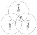
이하에서는 CoMP(Cooperative Multipoint Transmission/Reception)에 대하여 설명한다.Cooperative Multipoint Transmission / Reception (CoMP) will be described below.
LTE-A 이후의 시스템은 여러 셀들 간의 협력을 가능케 하여 시스템의 성능을 높이려는 방식을 도입하려고 한다. 이러한 방식을 협력 다중 포인트 송신/수신(Cooperative Multipoint Transmission/Reception: CoMP)이라고 한다. CoMP 는 특정 단말과 기지국, 액세스(Access) 포인트 혹은 셀(Cell)간의 통신을 보다 원활히 하기 위해 2 개 이상의 기지국, 액세스(Access) 포인트 혹은 셀이 서로 협력하여 단말과 통신하는 방식을 가리킨다. 본 발명에서 기지국, 액세스(Access), TP(Transmission Point) 혹은 셀은 같은 의미로 사용될 수 있다.After LTE-A, the system intends to introduce a way to improve system performance by enabling cooperation among multiple cells. This approach is referred to as Cooperative Multipoint Transmission / Reception (CoMP). A CoMP indicates a manner in which two or more base stations, access points or cells cooperate with each other to facilitate communication between a specific terminal and a base station, an access point or a cell. In the present invention, a base station, an access, a TP (Transmission Point), or a cell may be used in the same sense.
일반적으로, 주파수 재사용 인자(frequency reuse factor)가 1 인 다중-셀 환경에서, 셀-간 간섭(Inter-Cell Interference; ICI)으로 인하여 셀-경계에 위치한 단말의 성능과 평균 섹터 수율이 감소될 수 있다. 이러한 ICI를 저감하기 위하여, 기존의 LTE 시스템에서는 단말 특정 전력 제어를 통한 부분 주파수 재사용(fractional frequency reuse; FFR)과 같은 단순한 수동적인 기법을 이용하여 간섭에 의해 제한을 받은 환경에서 셀-경계에 위치한 단말이 적절한 수율 성능을 가지도록 하는 방법이 적용되었다. 그러나, 셀 당 주파수 자원 사용을 낮추기보다는, ICI를 저감하거나 ICI를 단말이 원하는 신호로 재사용하는 것이 보다 바람직할 수 있다. 위와 같은 목적을 달성하기 위하여, CoMP 전송 기법이 적용될 수 있다.Generally, in a multi-cell environment with a frequency reuse factor of 1, the performance of a UE located at a cell boundary due to inter-cell interference (ICI) and average sector yield may be reduced have. In order to reduce such ICI, in a conventional LTE system, a simple passive technique such as fractional frequency reuse (FFR) through UE-specific power control is used, A method of allowing the terminal to have a proper yield performance has been applied. However, rather than lowering the frequency resource usage per cell, it may be more desirable to reduce the ICI or reuse the ICI as the desired signal. In order to achieve the above object, the CoMP transmission scheme can be applied.
도 11은 CoMP를 수행하는 일 예를 나타낸다. 도 11을 참조하면, 무선 통신 시스템은 CoMP를 수행하는 복수의 기지국(BS1, BS2 및 BS3)과 단말을 포함한다. CoMP를 수행하는 복수의 기지국(BS1, BS2 및 BS3)은 서로 협력하여 단말에게 데이터를 효율적으로 전송할 수 있다.Fig. 11 shows an example of performing CoMP. Referring to FIG. 11, a wireless communication system includes a plurality of base stations BS1, BS2, and BS3 that perform CoMP and terminals. A plurality of base stations (BS1, BS2, and BS3) performing CoMP can efficiently transmit data to the terminals in cooperation with each other.
하향링크의 경우 CoMP 전송 방식은 다음과 같은 방식들로 구분될 수 있다.In the case of downlink, the CoMP transmission scheme can be classified into the following methods.
먼저, JP(Joint Processing) 방식에서, 단말은 CoMP 전송 방식을 수행하는 복수의 기지국으로부터 데이터를 동시에 수신할 수 있다.First, in a JP (Joint Processing) scheme, a UE can simultaneously receive data from a plurality of base stations performing a CoMP transmission scheme.
다음으로, JT(Joint Transmission) 방식에서, 단말은 CoMP 전송 방식을 수행하는 복수의 기지국으로부터 수신한 신호를 결합하여 수신 성능을 향상시킬 수 있다.Next, in a Joint Transmission (JT) scheme, a UE can combine signals received from a plurality of base stations performing a CoMP transmission scheme to improve reception performance.
다음으로, DPS(Dynamic Cell Selection) 방식에서, CoMP 전송 방식을 수행하는 복수의 기지국 중 하나는 특정 시점에 단말로 데이터를 전송한다.Next, in the DPS (Dynamic Cell Selection) scheme, one of the plurality of base stations performing the CoMP transmission scheme transmits data to the mobile station at a specific point in time.
다음으로, DPB(Dynamic Cell Blanking) 방식에서, CoMP 전송 방식을 수행하는 복수의 기지국 중 간섭을 주는 이웃 기지국을 동적으로(dynamically) 뮤팅(muting)하는 것을 통해 단말은 서빙 기지국으로부터의 수신 효율을 향상시킬 수 있다.Next, in a DPB (Dynamic Cell Blanking) scheme, a UE performs dynamically muting of a neighboring base station that provides interference among a plurality of base stations performing a CoMP transmission scheme, thereby improving reception efficiency from a serving base station .
협력 스케줄링/빔포밍 방식(CoMP - Coordinated Scheduling/beamforming, CoMP-CS/CB)의 경우, 단말은 빔포밍을 통해 데이터를 순간적으로 하나의 기지국, 즉 서빙 기지국을 통해 수신할 수 있다.In the case of Coordinated Scheduling / Beamforming (CoMP-CS / CB), the UE can instantaneously receive data through beamforming through one base station, that is, a serving base station.
상향링크에서 조인트 프로세싱(CoMP-JP) 방식이 적용되는 경우, 복수의 기지국이 단말로부터 PUSCH 신호를 동시에 수신할 수 있다(Joint Reception, JR). 이와 달리, 협력 스케줄링/빔포밍 방식(CoMP-CS/CB)의 경우, 하나의 기지국만이 PUSCH를 수신할 수 있다. 협력 스케줄링/빔포밍 방식을 사용하기로 하는 결정은 협력 셀(혹은 기지국)들에 의해 결정될 수 있다.When a joint processing (CoMP-JP) scheme is applied in an uplink, a plurality of base stations can simultaneously receive a PUSCH signal from a mobile station (Joint Reception, JR). Alternatively, in the cooperative scheduling / beamforming scheme (CoMP-CS / CB), only one base station can receive the PUSCH. The decision to use the cooperative scheduling / beamforming scheme may be determined by the cooperating cell (or base stations).
협력적 송신(CoMP) 시스템의 채널상태정보(CSI) 피드백Cooperative transmission (CoMP) system channel state information (CSI) feedback
CoMP 전송 방식을 사용하는 단말, 즉 CoMP UE는 CoMP 전송 방식을 수행하는 기지국들 복수에 대해서 채널정보를 피드백(feedback, 이하 CSI 피드백)할 수 있다. 네트워크 스케줄러(Network Scheduler)는 CSI 피드백을 기반으로 CoMP-JP, CoMP-CS/CB 및 DPS 방식 중에서 전송률을 높일 수 있는 적절한 CoMP 전송 방식을 선택할 수 있다. 그러기 위하여, CoMP UE가 CoMP 전송 방식을 수행하는 복수 개의 기지국들 내에서 CSI 피드백을 설정(configure)하는 방법으로, 상향링크 PUCCH를 이용한 주기적인 피드백 전송 방식을 따를 수 있다. 이 경우, 각각의 기지국에 대한 피드백 구성(feedback configuration)은 상호 독립적일 수 있다. 따라서, 이하 본 발명의 일 실시예에 따른 명세서에서는 이러한 독립적인 피드백 구성을 가지고 채널 정보를 피드백하는 동작 각각을 CSI 프로세스(CSI process)라고 호칭한다. 이러한 CSI 프로세스는, 하나의 서빙 셀에 하나 또는 그 이상 존재할 수 있다.A UE using a CoMP transmission scheme, i.e., a CoMP UE, can feedback channel information (CSI feedback) to a plurality of base stations performing a CoMP transmission scheme. Network Scheduler can select the appropriate CoMP transmission method to increase the transmission rate among CoMP-JP, CoMP-CS / CB and DPS based on CSI feedback. To this end, the CoMP UE may configure the CSI feedback in a plurality of base stations performing the CoMP transmission scheme, and may follow the periodic feedback transmission scheme using the uplink PUCCH. In this case, the feedback configuration for each base station may be mutually independent. Accordingly, in the specification of the present invention, each operation for feedback of channel information with such independent feedback configuration is referred to as a CSI process. Such a CSI process may be present in one or more serving cells.
도 12은 하향링크 CoMP 동작을 수행하는 경우를 나타낸다.12 shows a case where a downlink CoMP operation is performed.
도 12에서, UE는 eNB1과 eNB2사이에 위치하며, 두 eNB(즉, eNB1, eNB2)는 UE로의 간섭 문제를 해결하기 위해서 JT, DCS, CS/CB와 같은 적절한 CoMP 동작을 수행한다. UE는 기지국의 CoMP 동작을 돕기 위하여 CSI 피드백(CSI feedback)을 수행한다. CSI 피드백을 통하여 전송되는 정보는 각 eNB의 PMI 정보와 CQI 정보를 포함하며, 추가적으로 JT를 위한 두 eNB 사이의 채널 정보(예를 들어, 두 eNB 채널 사이의 위상 오프셋(phase offset) 정보)를 포함할 수 있다.In Figure 12, the UE is located between eNB1 and eNB2, and two eNBs (eNB1, eNB2) perform appropriate CoMP operations such as JT, DCS, CS / CB to resolve the interference problem to the UE. The UE performs CSI feedback to assist the CoMP operation of the base station. The information transmitted through the CSI feedback includes PMI information and CQI information of each eNB and additionally includes channel information between two eNBs for JT (for example, phase offset information between two eNB channels) can do.
도 12에서, UE는 자신의 서빙 셀(serving cell)인 eNB1으로 CSI 피드백 신호를 전송하고 있지만, 상황에 따라 eNB2로 CSI 피드백 신호를 전송하거나 두 eNB로 모두 CSI 피드백 신호를 전송 할 수 있다. 또한, 도 12에서는 CoMP에 참여하는 기본 단위를 eNB로 설명하고 있으나, eNB뿐만 아니라 eNB에 의해서 제어 되는 전송 포인트(transmission point)도 CoMP에 참여하는 기본 단위가 될 수 있다.In FIG. 12, the UE transmits the CSI feedback signal to the
네트워크에서 CoMP 스케줄링을 하기 위해서 UE는 서빙 eNB의 하향링크 CSI 정보뿐만 아니라 CoMP에 참여하는 이웃 eNB의 하향링크 CSI 정보도 함께 피드백 해야 한다. 이를 위하여 UE는 다양한 데이터 전송 eNB와 다양한 간섭 환경을 반영하는 복수의 CSI 프로세스를 피드백 하게 된다.In order to perform CoMP scheduling in the network, the UE must feedback not only the downlink CSI information of the serving eNB but also the downlink CSI information of the neighboring eNB participating in CoMP. To this end, the UE feeds back a plurality of data transmission eNBs and a plurality of CSI processes reflecting various interference environments.
따라서, LTE 시스템에서 CoMP CSI 계산 시 간섭 측정을 위해 IMR(Interference Measurement Resource)이 사용된다. 하나의 UE는 복수 개의 IMR을 설정(configure)받을 수 있으며, 상기 복수 개의 IMR 각각에 대하여 독립적인 설정(configuration)을 가진다. 즉, 각각의 IMR은 주기와 오프셋(offset) 그리고 자원 설정(resource configuration)이 독립적으로 설정되며, 기지국은 RRC(Radio Resource Control) 시그널링 등의 상위계층 시그널링(RRC등)을 이용하여 UE에게 시그널링할 수 있다.Therefore, IMR (Interference Measurement Resource) is used for interference measurement in CoMP CSI calculation in LTE system. One UE may be configured to configure a plurality of IMRs and have independent configurations for each of the plurality of IMRs. That is, each IMR is independently configured with a period, an offset, and a resource configuration, and the base station signals to the UE using upper layer signaling (RRC, etc.) such as RRC (Radio Resource Control) .
또한, LTE system에서 CoMP CSI 계산 시 요구되는(desired) 채널 측정을 위해 CSI-RS가 사용된다. 하나의 UE는 복수 개의 CSI-RS를 설정(configure)받을 수 있으며, 이때 CSI-RS은 각각 독립적인 설정(configuration)을 가진다. 즉, 각 CSI-RS은 주기와 오프셋(offset) 그리고 자원 할당(resource configuration), 전력 제어(power control, Pc), 안테나 포트(antenna port) 수가 독립적으로 설정된다. CSI-RS와 관련된 정보는 상위 계층 시그널링(RRC 등)을 통해 기지국으로부터 UE에게 전송될 수 있다.In addition, in the LTE system, CSI-RS is used for desired channel measurement in CoMP CSI calculation. One UE can configure a plurality of CSI-RSs, and each CSI-RS has an independent configuration. That is, each CSI-RS is independently set to have a number of cycles, an offset, a resource configuration, a power control (Pc), and an antenna port. Information related to the CSI-RS may be transmitted from the base station to the UE via higher layer signaling (such as RRC).
UE에게 설정된 복수 개의 CSI-RS 와 복수 개의 IMR 중에서, 신호 측정을 위한 하나의 CSI-RS 자원과, 간섭 측정을 위한 하나의 Interference Measurement Resource (IMR)을 연관하여(association) 하나의 CSI process가 정의될 수 있다. UE는 서로 다른 CSI process로부터 유도된 CSI 정보는 독립적인 주기와 서브프레임 오프셋(subframe offset)으로 피드백한다.One CSI-RS resource for signal measurement and one Interference Measurement Resource (IMR) for interference measurement among a plurality of CSI-RSs and a plurality of IMRs set for the UE are associated with each other. . The UE feeds back CSI information derived from different CSI processes to an independent period and a subframe offset.
즉, 각각의 CSI process는 독립적인 CSI 피드백 설정을 갖는다. 이러한 CSI-RS 자원과 IMR 자원의 연관(association) 정보 및 CSI 피드백 설정 등은 CSI process 별로 RRC등의 상위 계층 시그널링을 통해 기지국이 UE에게 알려줄 수 있다. 예를 들어, UE는 표 1과 같은 세 개의 CSI process를 설정(configure)받는다고 가정한다.That is, each CSI process has independent CSI feedback settings. The base station can inform the UE of the association information of the CSI-RS resource and the IMR resource and the CSI feedback setting through the upper layer signaling such as RRC for each CSI process. For example, the UE assumes that three CSI processes as shown in Table 1 are configured.

표 1에서 CSI-RS 0와 CSI-RS 1는 각각 UE의 serving eNB인 eNB 1으로부터 수신하는 CSI-RS와 협력에 참여하는 이웃 eNB인 eNB 2로부터 수신하는 CSI-RS를 나타낸다. 만약 표 1의 각각의 CSI process에 대하여 설정된 IMR에 대하여 표 2와 같이 설정되었다고 가정한다면,In Table 1, CSI-

IMR 0에서 eNB 1은 muting을 eNB 2는 데이터 송신을 수행하며, UE는 IMR 0 로 부터 eNB 1을 제외한 다른 eNB들로부터의 간섭을 측정하도록 설정된다. 마찬가지로, IMR 1에서 eNB 2은 muting을 eNB 1는 데이터 송신을 수행하며, UE는 IMR 1 로부터 eNB 2을 제외한 다른 eNB들로부터의 간섭을 측정하도록 설정된다. 또한, IMR 2에서 eNB 1과 eNB 2 모두 muting을 수행하며, UE는 IMR 2 로부터 eNB 1과 eNB 2을 제외한 다른 eNB들로부터의 간섭을 측정하도록 설정된다.In
따라서, 표 1 및 표 2에서 나타낸 바와 같이, CSI process 0의 CSI 정보는 eNB 1으로부터 데이터를 수신하는 경우 최적 RI, PMI, CQI 정보를 나타낸다. CSI process 1의 CSI 정보는 eNB 2으로부터 데이터를 수신하는 경우 최적 RI, PMI, CQI 정보를 나타낸다. CSI process 2의 CSI 정보는 eNB 1으로부터 데이터를 수신하고, eNB 2로부터 간섭을 전혀 받지 않는 경우 최적 RI, PMI, CQI 정보를 나타낸다.Therefore, as shown in Table 1 and Table 2, the CSI information of
기준(reference) CSI 프로세스Reference CSI process
하나의 UE에게 설정(configure)된 CSI 프로세스(process)는 CoMP 스케줄링(scheduling)의 효율성을 위하여 서로 종속적인 값을 공유하는 것이 바람직하다. 예를 들어 TP(Transmission point) 1 과 TP 2가 JT(joint transmission)하는 경우, 제1 셀에 대한 제1 CSI 프로세스와 제2 셀에 대한 제2 CSI 프로세스는 RI 및 선택된 서브밴드 인덱스(selected subband index)가 같아야 JT의 스케줄링이 용이해진다.The CSI processes configured for one UE preferably share mutually dependent values for the efficiency of CoMP scheduling. For example, when TP (Transmission Point) 1 and
따라서, UE에게 설정된 CSI 프로세스 중 일부 또는 전부의 CSI 프로세스는 공통된(common) CSI (예를 들면, RI, PMI, 또는 selected subband index 등)을 가지도록 제한될 수 있다. 설명의 편의를 위하여, 공통된 CSI 값을 가지도록 제한된 CSI 프로세스 중 CSI 값 설정의 기준이 되는 CSI 프로세스를 기준(reference) CSI 프로세스라 칭하고, 기준 CSI 프로세스를 제외한 나머지 CSI 프로세스를 연계(linked) CSI 프로세스라 칭한다. 연계 CSI 프로세스는 별도의 계산 없이 기준 CSI 프로세스의 CSI 값과 동일한 값을 그대로 피드백 할 수 있다.Thus, some or all of the CSI processes set for the UE may be restricted to have a common CSI (e.g., RI, PMI, or selected subband index, etc.). For convenience of explanation, a CSI process that is a reference for setting a CSI value among a limited CSI process having a common CSI value is referred to as a reference CSI process, and a remaining CSI process except a reference CSI process is referred to as a linked CSI process Quot; The associated CSI process can feed back the same value as the CSI value of the reference CSI process without further calculation.
예를 들면, 연계 CSI 프로세스의 CSI는, 해당 CSI의 보고(reporting) 시점 또는 그 이전에, 기준 CSI 프로세스가 가장 최근에 보고한 CSI로 설정된다. 또한, 설명의 편의를 위하여 기준 CSI 프로세스와 연계 CSI 프로세스가 공통 RI를 갖는 경우에 대하여 설명하였으나, 본 발명은 이에 국한되지 않고 공통 PMI 또는 공통 selected subband index를 가지는 경우에도 적용될 수 있다. 이하에서는, 연계 CSI 프로세스의 RI를 기준 RI라 칭하고, 연계 CSI 프로세스의 RI를 연계 RI라 칭한다.For example, the CSI of a linked CSI process is set to the most recently reported CSI of the reference CSI process at or before the reporting time of the corresponding CSI. Also, for convenience of description, the case where the reference CSI process and the associated CSI process have a common RI has been described. However, the present invention is not limited to this case, but may be applied to a case having a common PMI or a common selected subband index. Hereinafter, the RI of the linked CSI process is referred to as a reference RI, and the RI of the linked CSI process is referred to as a linked RI.
협력적 송신(CoMP) 전송 방식의 비교Comparison of cooperative transmission (CoMP) transmission methods
먼저, 상술한 CoMP 전송 방식 중 DPB 방식(scheme)과 JT 방식의 성능을 비교한다.First, the performance of the DPB scheme and the JT scheme among the CoMP transmission schemes described above are compared.
UE 의 SINR(Signal to Interference plus Noise Ratio) 측면에서, DPB와 JT는 SINR의 분모를 구성하는 간섭(interference) 및 잡음(noise)의 영향을 동일하게 받는다. 반면, 상기 두 CoMP 방식은 SINR의 분자를 구성하는 신호 전력(signal power)에서 차이가 난다. DPB는 한 TP로부터 신호 전력(signal power)을 수신하지만, JT는 복수의 TP로부터 신호 전력(signal power)을 수신한다. 구체적으로 JT 에 참여하는 TP 1으로부터 수신되는 신호 전력(signal power)을 s1, TP 2로부터 수신되는 신호 전력을 s2 라 가정할 때,

네트워크 관점에서, DPB는 JT와 다르게 협력에 참여하는 인접 TP가 간섭 제거를 위해 전력(power)을 뮤팅(muting)함으로서 상기 인접 TP로부터 간섭을 받고 있는 모든 셀(cell)이 간섭 완화(mitigation)의 혜택을 볼 수 있다. 따라서 네트워크 관점에서 DPB는 JT 보다 높은 성능을 제공할 수 있다.From a network point of view, the DPB may be configured to mutate power for interference cancellation by neighboring TPs participating in the cooperation differently from JT, so that all cells that are interfered with by the adjacent TPs can perform interference mitigation Benefits can be seen. Therefore, from a network point of view, DPB can provide higher performance than JT.
따라서, DPB와 JT 방식을 UE 및 네트워크 관점에서 고려할 때, 코히어런트(coherent) JT일 지라도 6dB 이득(gain)이 랭크(rank) 증가로 이어지지 않는다면, 인접 셀 모두가 간섭 제거의 이득을 볼 수 있는 DPB를 적용하는 것이 효율적이다. 즉 DPB와 비교해서 JT의 랭크(rank)가 더 크다면 UE 관점에서 랭크(rank) 증가로 인한 처리량(throughput)의 향상(enhancement)이 크기 때문에, 다른 셀에게 여전히 간섭을 주더라도 JT를 적용하는 것이 효율적이다. 마찬가지로 논-코히어런트(non-coherent) JT의 경우도 DPB와 비교하여 신호 전력 이득(signal power gain)에 따라 랭크(rank) 증가로 이어지는 경우 JT가 더 효율적이다.Therefore, when considering the DPB and JT schemes from the UE and network perspectives, even if the coherent JT does not lead to a 6dB gain increase in rank, all of the adjacent cells can see the gain of interference cancellation It is effective to apply the DPB. That is, if the rank of JT is larger than that of DPB, the enhancement of the throughput due to the rank increase is large from the viewpoint of the UE. Therefore, even if the cell still interferes with other cells, It is efficient. Similarly, for non-coherent JT, JT is more efficient if it leads to a rank increase according to signal power gain as compared to DPB.
다음으로, 상술한 CoMP 전송 방식 중 DPS 방식과 JT 방식의 성능을 비교한다.Next, the performance of the DPS scheme and the JT scheme among the CoMP transmission schemes described above are compared.
UE의 관점에서 JT는 신호 전력(signal power) 뿐만 아니라 인접 셀로부터의 간섭도 제거된 상태이기 때문에 SINR 측면에서 JT는 DPS보다 이득(gain)이 크다. 하지만 협력에 참여하는 인접 셀의 데이터 트래픽(data traffic)이 낮고 서빙 셀의 트래픽(traffic)이 높은 경우, DPS는 JT 보다 더 좋은 성능을 제공할 수 있다. 왜냐하면, DPS 에서는 인접 셀의 남는 자원을 스케줄링 경쟁 없이 UE가 점유할 수 있기 때문이다.In terms of UE, JT has higher gain than DPS in terms of SINR since JT is not only in signal power but also interference from adjacent cell. However, if data traffic of neighboring cells participating in cooperation is low and traffic of the serving cell is high, DPS can provide better performance than JT. This is because, in the DPS, the UE can occupy the remaining resources of the neighboring cells without scheduling competition.
네트워크 관점에서도, 협력에 참여하는 인접 셀의 데이터 트래픽(data traffic)이 낮고 서빙 셀의 트래픽(traffic)이 높은 경우, DPS는 효과적인 자원 운용을 가능하게 한다. 즉 이 경우 DPS는 서빙 셀의 높은 트래픽(traffic)을 분산 시켜 나머지 서빙 셀의 UE들의 처리량(throughput)을 증가 시키고, 인접 협력 셀의 유휴 자원을 이용하여 자원 이용률을 증가 시킨다.From a network point of view, when data traffic of neighboring cells participating in cooperation is low and the traffic of the serving cell is high, the DPS enables effective resource operation. That is, in this case, the DPS increases the throughput of the UEs of the remaining serving cells by dispersing high traffic of the serving cell, and increases the resource utilization rate by using the idle resources of the adjacent cooperative cells.
따라서, DPS와 JT 방식을 UE 및 네트워크 관점에서 고려할 때, JT에서 DPS대비 SINR 이득(gain)이 증가하더라도 랭크(rank) 증가로 이어지지 않는다면, DPS를 적용하는 것이 효율적이다. 즉 DPS와 비교해서 JT의 랭크(rank)가 더 크다면 UE 처리량(throughput) 관점에서 랭크(rank) 증가로 인한 처리량(throughput)의 향상(enhancement)이 크기 때문에, 트래픽(traffic) 분산이 완벽하게 되지 않더라도 JT를 적용하는 것이 효율적이다.Therefore, when considering the DPS and JT schemes from the viewpoints of UE and network, it is effective to apply DPS if the increase in SINR gain compared to DPS does not lead to a rank increase in JT. That is, when the rank of the JT is larger than that of the DPS, the enhancement of the throughput due to the increase of the rank in terms of the UE throughput is large, It is effective to apply JT even if it is not.
본 발명에 따른 CoMP-JT 적용 방법CoMP-JT application method according to the present invention
따라서, 본 발명에 따른 피드백 방법은 다중(multiple) CSI 프로세스 중 일부 CSI 프로세스를 이용하여 JT CSI를 계산하고, 각 CSI 프로세스를 기준으로 계산된 랭크(rank) 값 보다 JT CSI의 랭크(rank)가 클 경우, 상기 일부 CSI 프로세스 중 일부 또는 전부의 CSI 프로세스의 피드백(feedback)을 JT CSI 피드백으로 설정하는 특징을 제공한다.Therefore, the feedback method according to the present invention calculates JT CSI using a part of CSI processes among multiple CSI processes, and calculates a rank of JT CSI from a rank value calculated on the basis of each CSI process The feedback of the CSI process of some or all of the some CSI processes is set to JT CSI feedback.
즉, 기지국은 DPB 또는 DPS에 필요한 다중 CSI 프로세스를 UE에게 할당하고 그 중 JT CSI 계산을 위해 이용되는 일부 CSI 프로세스를 지정한다. UE는 상기 일부 CSI 프로세스를 이용하여 JT CSI를 추가적으로 계산하고, 각 CSI 프로세스에 상응하는 랭크 값에 비하여 랭크의 증가가 있을 경우, 상기 일부 CSI 프로세스 중 적어도 하나의 CSI 피드백을 JT CSI 피드백으로 대체하여 보고(report)한다. UE는 기지국으로 적어도 하나의 CSI 프로세스의 CSI 피드백이 JT CSI 피드백으로 대체되었음을 알리는 신호를 전송한다. JT CSI 계산을 위해 이용되는 일부 CSI 프로세스 중 어떤 CSI 프로세스의 피드백이 JT CSI 피드백으로 대체되었는지에 대한 신호도 전송할 수 있다.That is, the base station assigns to the UE a multi-CSI process required for DPB or DPS, and designates some CSI process used for JT CSI calculation. The UE additionally calculates the JT CSI using the partial CSI process and replaces at least one CSI feedback among the CSI processes with JT CSI feedback when there is an increase in rank compared to the rank value corresponding to each CSI process Report. The UE sends a signal to the base station indicating that the CSI feedback of at least one CSI process has been replaced by the JT CSI feedback. It may also send a signal as to which of the some CSI processes used for JT CSI calculation has been replaced by JT CSI feedback.
예를 들며, UE에게 표 1 및 표 2에 해당하는 세 개의 CSI 프로세스가 설정되었을 때, CSI 프로세스 0, 1, 2는 각각 non-CoMP, DPS, DPB를 목적(target)으로 할 수 있다. 이하에서는, 상기 CSI 프로세스 0, 1, 2를 예로 들어 본 발명에 따른 피드백 방법을 설명한다.For example, when three CSI processes corresponding to Tables 1 and 2 are set in the UE, the CSI processes 0, 1 and 2 may be targets of non-CoMP, DPS, and DPB, respectively. Hereinafter, the feedback method according to the present invention will be described taking
먼저, 기지국은 다중 CSI 프로세스 중 JT CSI 계산을 위해 이용되는 일부 CSI 프로세스를 지정한다.First, the base station specifies some CSI processes used for JT CSI calculation among multiple CSI processes.
기지국은 UE에게 상기 세 CSI 프로세스 중 JT CSI 계산을 위해 이용되는 일부 CSI 프로세스를 지정한다. 기지국은 상위 계층 시그널링(예를 들면, RRC 시그널링)을 이용한 수 있다. 또는, 기지국은 JT CSI 계산을 위해 이용되는 일부 CSI 프로세스를 미리 정하여 설정할 수 있다. 2 개의 TP 간에 JT가 적용되는 경우를 예를 들면, 기지국은 CSI 프로세스 1및 2를 JT CSI 계산을 위한 CSI 프로세스로 미리 설정할 수 있다.The base station designates some CSI processes used for JT CSI calculation among the three CSI processes to the UE. The base station may use higher layer signaling (e.g., RRC signaling). Alternatively, the base station can preset and set up some CSI processes used for JT CSI calculation. For example, when JT is applied between two TPs, the base station can preset CSI processes 1 and 2 as CSI processes for JT CSI calculation.
다음으로, UE는 JT CSI를 계산한다.Next, the UE calculates JT CSI.
UE는, 종래의 방식대로 각 CSI 프로세스 별로 CSI를 계산하는 것에 더하여, 상기 지정된 CSI 프로세스(예를 들면, CSI 프로세스 1 및 2)를 이용하여 JT CSI를 계산한다. JT CSI 계산을 위해서는 채널 측정과 간섭 측정이 필요하다.The UE calculates JT CSI using the specified CSI process (for example, CSI processes 1 and 2) in addition to calculating CSI for each CSI process in a conventional manner. JT CSI calculations require channel measurements and interference measurements.
채널 측정을 위하여 UE는 CSI 프로세스 1의 CSI-RS와 CSI 프로세스 2의 CSI-RS 각각의 채널을 추정하고, 추정된 채널을 각각 H1, H2라고 할 때 하나의 합성(composite) 채널 [H1 H2]을 형성한다.For the channel measurement, the UE estimates the CSI-RS of the CSI-RS of the
간섭 측정을 위하여 UE는 CSI 프로세스 1의 IMR과 CSI 프로세스 2의 IMR 중 하나를 이용한다. 어떤 IMR을 이용할 지는 기지국이 UE에게 상위 계층 시그널링(예를 들면, RRC 시그널링)을 통해 알려 줄 수 있다. 또는, UE는 JT CSI 계산을 위해 사용될 일부 CSI 프로세스 중 가장 낮은 인덱스(lowest index)를 갖는 CSI 프로세스의 IMR을 이용할 수 있다. JT에 대한 채널과 간섭 측정을 수행한 이후, UE는 이를 바탕으로 최적 JT 랭크, JT PMI, JT CQI를 계산한다.For interference measurement, the UE uses one of the IMR of
JT PMI는 CSI 프로세스 1의 PMI와 CSI 프로세스 2의 PMI 두 개로 구성되며, 각 PMI는 각 CSI 프로세스의 CSI-RS 포트(port) 수를 기준으로 선택된 코드북(codebook)에서 결정된다. 예를 들어, CSI 프로세스 1과 프로세스 2의 CSI-RS 포트수가 각각 4와 2 인 경우, CSI 프로세스 1의 PMI는 4 Tx(전송 안테나) 코드북을 이용하여 찾고, CSI 프로세스 2의 PMI는 2 Tx 코드북을 이용하여 찾는다.JT PMI consists of two PMIs of
또는, JT PMI는 하나의 PMI로 구성되며, JT PMI를 전송을 위한 코드북을 CSI 프로세스 1과 프로세스 2의 CSI-RS 포트수의 합을 기준으로 결정할 수 있다. 예를 들어 CSI 프로세스 1과 프로세스 2의 CSI-RS 포트수가 각각 4 인 경우 8 Tx 코드북을 이용하여 JT PMI를 결정한다.Alternatively, the JT PMI is composed of one PMI, and the codebook for transmitting the JT PMI can be determined based on the sum of the number of CSI-RS ports of
한편, UE는 계산량을 줄이기 위해서 모든 JT CSI를 계산하지 않고, JT RI만 우선 계산한 뒤, 이하의 방식을 통해 JT CSI 보고의 수행을 결정한 이후 JT PMI와 JT CQI등을 계산할 수 있다.On the other hand, the UE can calculate JT PMI and JT CQI after determining JT CSI report through the following method after calculating JT RI only without calculating all JT CSI in order to reduce the calculation amount.
다음으로, UE는 JT CSI의 보고 여부를 판단한다.Next, the UE determines whether to report the JT CSI.
UE는 각 CSI 프로세스의 CSI와 JT CSI를 모두 계산 한 뒤, 적용 기준에 따라 JT CSI를 보고할 지 결정하고, JT CSI를 보고하는 경우 제어 채널을 통해 이를 기지국에게 알린다.After calculating both CSI and JT CSI of each CSI process, the UE determines whether to report the JT CSI according to the application criteria, and notifies the base station through the control channel when reporting JT CSI.
JT CSI를 보고하는지 여부에 대한 적용 기준은 다양하게 설정될 수 있으나, 상술한 바와 같이 랭크 값의 증가를 기준으로 하는 것이 효율적이다. 즉, JT CSI의 계산을 위해 이용된 CSI 프로세스의 각 랭크 값과 JT 랭크 값을 비교하여 JT 랭크가 기준값 이상 클 경우 UE는 JT CSI를 보고 한다. 기준값은 기지국과 UE가 약속한 고정된(static) 값이거나 상위 계층 시그널링(예를 들면, RRC 시그널링)으로 기지국이 UE에게 알려 주는 반정적(semi-static) 정보일 수 있다. 이하에서는 설명의 편의를 위하여, 기준값을 1로 가정한다. 예를 들면, JT CSI 계산을 위해 이용된 CSI 프로세스의 랭크 값 중 최대 값 보다 JT 랭크 값이 클 경우 UE는 JT CSI를 보고 한다.The application criteria for whether or not to report JT CSI can be variously set, but it is effective to base the increase in the rank value as described above. That is, when each rank value of the CSI process used for calculating JT CSI is compared with the JT rank value, the UE reports JT CSI when the JT rank is larger than the reference value. The reference value may be a static value that the base station and the UE promise or semi-static information that the base station informs the UE in higher layer signaling (e.g., RRC signaling). Hereinafter, for convenience of explanation, it is assumed that the reference value is 1. For example, if the JT rank value is larger than the maximum value among the rank values of the CSI process used for the JT CSI calculation, the UE reports the JT CSI.
또한, UE는 JT CSI 계산을 위해 이용된 CSI 프로세스뿐만 아니라 UE에 설정된 모든 CSI 프로세스의 각 랭크를 JT 랭크 값과 비교하여 JT CSI의 보고 여부를 판단할 수도 있다.In addition, the UE may determine whether to report JT CSI by comparing each rank of all CSI processes set in the UE with the JT rank value, as well as the CSI process used for JT CSI calculation.
UE는 JT CSI의 보고를 결정한 경우, 기지국으로 JT CSI 를 보고한다는 정보를 전송한다. 예를 들면, JT CSI의 보고 여부에 대한 값은 1 비트(bit)로 RI와 함께 전송할 수 있다.When the UE determines the JT CSI report, it transmits information that it reports the JT CSI to the base station. For example, the value of whether or not to report JT CSI can be transmitted with RI in 1 bit.
다음으로, UE는 JT CSI를 기지국으로 보고한다.Next, the UE reports the JT CSI to the base station.
상술한 판단 결과, UE가 JT CSI의 보고를 결정하면, JT CSI 계산에 이용된 CSI 프로세스 중 적어도 하나의 또는 모두의 CSI 피드백을 JT CSI 피드백으로 대체한다.As a result of the above determination, if the UE determines the reporting of the JT CSI, it replaces at least one or both of the CSI feedbacks used in the JT CSI calculation with JT CSI feedback.
한편, 상기 JT CSI 계산과 보고 방법은 3D MIMO 또는 Massive MIMO 시스템을 위한 CSI 피드백에도 그대로 적용할 수 있다. 3D MIMO 시스템에서 송신 안테나의 개수가 M개로 (예를 들어 M=128) 증가 함에따라 UE는 기존 보다 많은 송신 안테나에 상응하는 RS를 참조하여 CSI를 리포트 한다. 이를 지원하기 위한 한가지 방식으로 기지국은 M개의 안테나를 N개 안테나 그룹(group)으로 나누고 각 그룹에 해당하는 RS를 송신한다. 예를 들어, 16개의 전체 송신 안테나를 8개씩 묶어 2 개의 안테나 그룹을 만들고 각 안테나 그룹에 해당하는 8 Tx CSI-RS를 CSI 프로세스 1과 CSI 프로세스 2로 나누어 UE에게 설정한다. 즉, UE는 CSI 프로세스 1을 설정받고 프로세스 1에서 설정된 안테나 그룹 1의 CSI-RS로 채널을 추정하여 CSI를 보고한다. 또한 CSI 프로세스 2를 설정받고 프로세스 2에서 설정된 안테나 그룹 2의 CSI-RS로 채널을 추정하여 CSI를 보고한다.Meanwhile, the JT CSI calculation and reporting method can be directly applied to CSI feedback for 3D MIMO or massive MIMO system. In the 3D MIMO system, as the number of transmit antennas increases by M (for example, M = 128), the UE reports CSI by referring to RSs corresponding to more transmit antennas than the existing ones. One way to support this is to divide the M antennas into N antenna groups and transmit the RS corresponding to each group. For example, 8 antenna groups are formed by grouping all 16 transmit antennas into 8 groups, and 8 Tx CSI-RS corresponding to each antenna group is divided into
상기와 같이 3D MIMO 시스템에서 송신 안테나의 부분 집합 별로 CSI 프로세스가 할당되었을 때, UE는 상기 JT CSI 리포트 방식을 활용할 수 있다. 즉, UE는 각 프로세스로부터 구한 RI와 복수 개의 CSI 프로세스의 CSI-RS로부터 결합 채널(composite channel)을 생성하여 계산한 매시브 안테나 전송(massive antenna transmission) RI를 비교하여 각 프로세스 별로 독립적으로 계산된 CSI를 보고할 지, 아니면 매시브 안테나 전송에 최적화된 매시브 안테나 전송(massive antenna transmission) CSI를 보고할 지 결정할 수 있다. 매시브 안테나 전송(massive antenna transmission) CSI는 상기 기술된 JT CSI 계산 방식을 그대로 이용하여 산출할 수 있다.As described above, when a CSI process is allocated to a subset of transmit antennas in a 3D MIMO system, the UE can utilize the JT CSI reporting method. That is, the UE generates a composite channel from the CSI-RS of a plurality of CSI processes and the RI obtained from each process, compares the calculated massive antenna transmission RI, Or to report a massive antenna transmission CSI that is optimized for massive antenna transmission. The massive antenna transmission CSI can be calculated using the JT CSI calculation method described above as it is.
이하에서는, JT CSI 계산에 이용된 모든 CSI 프로세스의 CSI 피드백을 JT CSI 피드백으로 대체하는 경우의 RI, PMI 및 CQI 피드백 방법에 대한 제1 실시예 및 CSI 계산에 이용된 CSI 프로세스 중 하나의 CSI 피드백을 JT CSI 피드백으로 대체하는 경우의 RI, PMI 및 CQI 피드백 방법에 대한 제2 실시예를 설명한다.Hereinafter, the first embodiment of the RI, PMI, and CQI feedback methods in the case of replacing the CSI feedback of all the CSI processes used in the JT CSI calculation with the JT CSI feedback and the CSI feedback of one of the CSI processes used in the CSI calculation A PMI and a CQI feedback method in the case of replacing the CQI feedback with the JT CSI feedback will be described.
제1 실시예First Embodiment
제1 실시예는 JT CSI 계산에 이용된 모든 CSI 프로세스의 CSI를 JT CSI 피드백으로 대체하는 방법이다. 이하에서는, 제1 실시예에 따라 RI, PMI 및 CQI를 산출하는 방법을 설명한다.The first embodiment is a method of replacing CSI of all the CSI processes used for JT CSI calculation with JT CSI feedback. Hereinafter, a method of calculating RI, PMI, and CQI according to the first embodiment will be described.
RI의 경우, JT CSI 계산에 이용된 모든 CSI 프로세스(예를 들면, CSI 프로세스 1과 2)에서 RI 대신 JT RI를 보고한다. JT RI의 최대값은 이하에서 PMI와 함께 설명한다.For RI, report all JT RIs instead of RI in all CSI processes used in JT CSI calculations (eg, CSI Processes 1 and 2). The maximum value of JT RI is described below with PMI.
PMI의 경우, JT CSI 계산에 이용된 CSI 프로세스의 PMI 는 상기 JT RI를 기준으로 계산된다. 예를 들어, JT 랭크 2가 피드백되는 경우 프로세스 1과 프로세스 2 모두 JT 랭크 2를 기준으로 PMI를 계산한다. 또한, UE는 기지국이 JT 전송을 한다고 가정했을 때 가장 높은 전송률을 달성할 수 있는 PMI를 선택하여 피드백한다. 프로세스 1과 2 각각을 통해 전송되는 상기 PMI를 JT PMI 1, JT PMI 2라 칭하고 두 PMI를 통틀어 JT PMI라고 칭한다.In the case of PMI, the PMI of the CSI process used in the JT CSI calculation is calculated on the basis of the JT RI. For example, when
JT PMI 1과 JT PMI 2는 각 CSI 프로세스의 CSI-RS 포트수를 기준으로 선택된 코드북에서 찾는다. 예를 들어 CSI 프로세스 1과 프로세스 2의 CSI-RS 포트수가 각각 4와 2 인 경우, JT PMI 1는 4 Tx 코드북을 이용하여 찾고, JT PMI 2는 2 Tx 코드북을 이용하여 찾는다. 이러한 방식에서, JT 랭크 값을 결정할 때 최대 랭크를 CSI 프로세스 1의 CSI-RS 포트수 및 CSI 프로세스 2의 CSI-RS 포트수 중 최소값으로 제한한다. 기지국이 JT CSI를 수신한 후, 실제 JT 전송을 하면 JT PMI 1과 JT PMI 2를 적절히 연접(concatenation)시켜 JT 프리코딩 행렬(precoding matrix)을 만든다. 반면, 기지국이 JT CSI를 수신한 후, 실제 JT 전송을 하지 않는다면, JT PMI 1과 JT PMI 2를 독립적인 프리코딩(precoding)으로 간주하고 최적 프리코더(Precoder)를 결정한다.
또는, JT PMI의 전송을 위한 코드북을 CSI 프로세스 1과 프로세스 2의 CSI-RS 포트수의 합을 기준으로 결정할 수도 있다. 예를 들어, CSI 프로세스 1과 프로세스 2의 CSI-RS 포트수가 각각 4 인 경우 8 Tx 코드북을 이용하여 JT PMI를 결정하고 JT PMI 1과 JT PMI 2는 동일한 JT PMI 값을 갖는다. 이러한 방식에서는 JT 랭크 값을 결정할 때 최대 랭크를 CSI 프로세스 1의 CSI-RS 포트수 및 CSI 프로세스 2의 CSI-RS 포트수의 합으로 제한한다. 기지국이 JT CSI를 수신한 후 JT PMI 1과 JT PMI 2가 같고 실제 JT 전송을 결정하면, JT PMI 1를 기준으로 JT 프리코딩 행렬(precoding matrix)을 생성한다. JT PMI 1과 JT PMI 2가 같지 않다면 디코딩 오류(decoding error)로 간주하여 JT 전송을 하지 않는다.Alternatively, a codebook for transmission of the JT PMI may be determined based on the sum of the numbers of CSI-RS ports of
CQI의 경우, JT CSI 계산에 이용된 CSI 프로세스의 CQI 는 상기 JT RI와 JT PMI를 기준으로 계산된다. CQI는 다음과 같이 결정될 수 있다.In the case of CQI, the CQI of the CSI process used in the JT CSI calculation is calculated based on the JT RI and the JT PMI. The CQI can be determined as follows.
제1 실시예에서 CQI를 계산하는 첫번째 방법은, JT CSI 계산에 이용된 CSI 프로세스 중 CSI 프로세스 i의 CQI 계산은 상기 JT 랭크와 JT PMI i를 기준으로 하되, CSI 프로세스 i의 CSI-RS와 IMR 만을 사용하여 CQI를 계산하는 것이다. 즉, JT 랭크와 JT PMI i를 사용하지만, 데이터 전송 채널과 간섭 환경은 각 CSI 프로세스 i에 정의된 고유 값을 사용하여 CQI를 계산한다. 설명의 편의를 위하여 CSI 프로세스 i 에 상응하는 상기 CQI 값을 부분(partial) JT CQI i라 칭한다. 부분 JT CQI는 JT 랭크와 JT PMI i를 사용했지만, 협력 셀들로부터 JT 전송을 가정하지 않았기 때문에, JT CQI 와는 다르다. 따라서 부분JT CQI를 수신한 기지국이 실제로 JT를 수행할 경우 보고된 부분 JT CQI를 적절히 보상하여 JT용 CQI를 다시 계산해야 한다. 반면, 기지국이 JT를 수행하지 않을 경우 부분 JT CQI를 기준으로 MCS를 설정한다.The first method of calculating the CQI in the first embodiment is based on the JT rank and the JT PMI i of the CSI process i of the CSI process used in the JT CSI calculation, To calculate the CQI. That is, although the JT rank and the JT PMI i are used, the data transmission channel and the interference environment calculate the CQI using the eigenvalues defined in each CSI process i. For convenience of explanation, the CQI value corresponding to the CSI process i is referred to as a partial JT CQI i. Partial JT CQI uses JT rank and JT PMI i, but it is different from JT CQI because JT transmission is not assumed from cooperating cells. Therefore, if the base station receiving the partial JT CQI actually performs the JT, the reported JT CQI should be appropriately compensated to recalculate the CQI for the JT. On the other hand, if the base station does not perform JT, MCS is set based on the partial JT CQI.
여기서, JT PMI의 전송을 위한 코드북을 CSI 프로세스 1과 프로세스 2의 CSI-RS 포트수의 합을 기준으로 결정하였다면, 부분 JT CQI i 계산 시 가정하는 PMI는 JT PMI i 의 행렬에서 CSI 프로세스 i의 CSI-RS 와 맵핑된 부분 행렬이다. 예를 들면, CSI 프로세스 1과 프로세스 2의 CSI-RS 포트수가 각각 4 인 경우 8 Tx 코드북을 이용하여 JT PMI를 결정하고, JT PMI 1의 행렬에서 1행부터 4행으로 구성된 부분 행렬을 프리코더로 가정하고 부분 JT CQI 1을 계산하고, JT PMI 2의 행렬에서 5행부터 8행으로 구성된 부분 행렬을 프리코더로 가정하고 부분 JT CQI 2 를 계산한다.If the codebook for transmission of JT PMI is determined based on the sum of the number of CSI-RS ports of
제1 실시예에서 CQI를 계산하는 두번째 방법은, JT CSI 계산에 이용된 CSI 프로세스 중 일부 CSI 프로세스에서는 JT CQI를 전송하고, 나머지 CSI 프로세스에서는 부분 JT CQI를 보고하는 것이다. JT CQI는 JT 전송이 이루어졌을 때의 추정 SINR을 기준으로 계산된다. 이때, JT CQI를 전송할 CSI 프로세스와 부분 JT CQI를 전송하는 CSI 프로세스는 상위 계층 시그널링(예를 들면, RRC 시그널링)을 통해 기지국이 지정하거나, 낮은 인덱스를 갖는 CSI 프로세스를 JT CQI를 전송하는 CSI 프로세스로 결정할 수 있다. 이 방식에서 UE는 JT RI, JT PMI를 기준으로 기지국이 JT를 수행했을 경우 예상되는 JT CQI를 계산하고 기지국으로 보고한다. 따라서 기지국이 JT를 수행하는 경우 JT CQI를 별도로 보상하지 않고 보고된 값을 그대로 사용할 수 있는 장점이 있다.The second method of calculating CQI in the first embodiment is to transmit JT CQI in some CSI processes and report partial JT CQI in the CSI process used for JT CSI calculation. The JT CQI is calculated based on the estimated SINR at the time of the JT transmission. At this time, the CSI process for transmitting the JT CQI and the CSI process for transmitting the partial JT CQI may be specified by the base station through higher layer signaling (e.g., RRC signaling), or may be a CSI process for transmitting the JT CQI . In this scheme, the UE calculates the expected JT CQI when the base station performs the JT based on the JT RI and the JT PMI, and reports to the base station. Therefore, when the BS performs the JT, the JT CQI is not compensated separately and the reported value can be used as it is.
만약, JT PMI를 전송을 위한 코드북을 CSI 프로세스 1과 프로세스 2의 CSI-RS 포트수의 합을 기준으로 결정하였다면, JT CQI 계산시, JT PMI 1 또는 JT PMI 2를 프리코더로 가정한다. 여기서, 상술한 바와 같이 JT PMI 1과 JT PMI 2는 동일하다.If the codebook for transmitting the JT PMI is determined based on the sum of the number of CSI-RS ports of
또한, JT PMI 1과 JT PMI 2가 각 CSI 프로세스의 CSI-RS 포트수를 기준으로 선택된 코드측에서 계산되었다면, JT CQI 계산시 JT PMI 1 과 JT PMI 2를 적절히 연접(concatenation)하여 프리코더로 가정한다. 예를 들면, JT PMI 1 과 JT PMI 2가 모두 4 Tx 코드북에서 선택되었다면 UE는 프리코딩 행렬(precoding matrix)의 첫 번째부터 네 번째 행(row)이 JT PMI 1으로 이루어져있고, 프리코딩 행렬의 다섯 번째부터 여덟 번째 행이 JT PMI 2로 이루어진 것으로 가정한다.In addition, if
제1 실시예에서 CQI를 계산하는 세번째 방법은, 상술한 첫번째 방법을 이용하되 추가적으로 일부 CSI 프로세스를 통해 JT CQI를 함께 전송하는 것이다. 예를 들면, 첫번째 방식으로 계산된 부분 JT CQI와 JT CQI의 차이를 추가적으로 전송할 수 있다.The third method of calculating the CQI in the first embodiment is to transmit the JT CQI together with some CSI processes using the first method described above. For example, the difference between the partial JT CQI calculated in the first method and the JT CQI can be additionally transmitted.
도 13은 제1 실시예의 피드백 방법에 따를 때 PUCCH 피드백의 실시예를 나타낸다.13 shows an embodiment of PUCCH feedback according to the feedback method of the first embodiment.
표 1 및 표 2에서 정의된 세 개의 CSI 프로세스가 UE에게 설정되고, 이 중 CSI 프로세스 1과 2 가 JT CSI 계산을 위해 지정된다. UE는 각 CSI 프로세스의 CSI 뿐만 아니라 CSI 프로세스 1 및 2 의 CSI-RS 및 IMR을 사용하여 JT CSI를 추가적으로 계산한다.Three CSI processes defined in Table 1 and Table 2 are set for the UE, of which CSI processes 1 and 2 are designated for JT CSI calculation. The UE additionally computes the JT CSI using the CSI-RS and IMR of the CSI processes 1 and 2 as well as the CSI of each CSI process.
RI 가 전송되는 시점에 각 CSI 프로세스의 RI와 JT RI를 비교하여 UE와 기지국이 약속한 특정 조건을 만족하면, 이후 다음 RI 전송 시점까지 JT CSI를 피드백 한다. 예를 들어, JT RI가 CSI 프로세스 1과 2의 각 RI 값보다 크다고 판단되면 UE는 JT CSI를 피드백 한다.When the RI is transmitted, the RI of each CSI process is compared with the JT RI, and if the UE and the base station satisfy the predetermined conditions promised, the JT CSI is fed back to the next RI transmission time. For example, if the JT RI is determined to be greater than the respective RI values of
구체적으로, 도 13의 실시예에서 UE가 서브프레임 39 에서 JT RI 는 2, 프로세스 1의 RI는 1, 프로세스 2의 RI는 1 로 계산하였다면, JT RI는 각 프로세스의 RI보다 크다. 따라서, 서브프레임 40과 41 각각에서 CSI 프로세스 1과 2를 통해 JT-RI를 피드백 한다. UE는 기지국에게 각 프로세스 별로 계산된 RI가 아닌 JT RI가 피드백 되었음을 알린다. 이 정보는 도 14와 같이 RTI (rank type indicator)로서, RI와 함께 엔코딩(encoding)되어 전송될 수 있다. RTI가 0인 경우 각 CSI 프로세스 별로 계산된 랭크를 의미하며, 1인 경우 JT 랭크를 의미할 수 있다. JT RI를 피드백 한 이후 다음 RI를 갱신(updated)하기 전 까지 JT-RI를 기준으로 JT PMI와 JT CQI를 계산하여 피드백한다. JT CQI는 상술한 세가지 JT CQI 계산 방식 중 하나를 통해 산출될 수 있다. UE가 RTI를 1로 설정한 경우 UE는 JT 스케줄링에 용이한 PMI, CQI 또는 TP 간 위상 보상 정보 등 다양한 값을 전송할 수 있다.Specifically, in the embodiment of FIG. 13, if JT RI is 2, RI of
PUCCH 피드백에서는 RI 피드백 주기가 길게 설정될 수 있으며, 이로 인해서 상술한 JT CSI 보고의 유효성(dynamics)이 제한될 수 있다. 하지만, 이러한 문제는 기지국이 RI 피드백 주기를 짧게 설정하여 해결될 수 있다. 또한, LTE-A 시스템을 예로 들면, CSI-RS 자체가 5msec 이상의 주기를 가지고 전송되기 때문에 본 실시예가 JT CSI 보고의 유효성(dynamics)을 떨어뜨린다고 보기 어렵다.In the PUCCH feedback, the RI feedback period may be set to be long, which may limit the dynamics of the JT CSI report described above. However, this problem can be solved by setting the RI feedback period shorter in the base station. In addition, since the CSI-RS itself is transmitted with a period of 5 msec or more in the LTE-A system as an example, it is difficult to see that the present embodiment lowers the dynamics of the JT CSI report.
제2 실시예Second Embodiment
제2 실시예는 CSI 계산에 이용된 CSI 프로세스 중 하나의 CSI 피드백을 JT CSI 피드백으로 대체하는 방법이다. 이하에서는, 제2 실시예에 따라, RI, PMI 및 CQI를 산출하는 방법을 설명한다.The second embodiment is a method of replacing CSI feedback of one of the CSI processes used for CSI calculation with JT CSI feedback. Hereinafter, a method of calculating RI, PMI, and CQI according to the second embodiment will be described.
이때, JT CSI를 피드백하는 하나의 CSI 프로세스는 상위 계층 시그널링(예를 들면, RRC 시그널링)으로 기지국이 UE에게 지정하거나, JT CSI 계산에 이용되는 CSI 프로세스 중 가장 낮은 인덱스의 CSI 프로세스로 지정할 수 있다. 표1 및 표2의 CSI 프로세스를 예로 들면, CSI 프로세스 1과 2를 이용하여 JT CSI를 계산할 때, UE는 가장 낮은 인덱스의 CSI 프로세스인 CSI 프로세스 1의 CSI를 JT CSI로 대체한다.At this time, one CSI process that feeds back the JT CSI can designate the base station as a higher-layer signaling (e.g., RRC signaling) to the UE, or designate it as the lowest index CSI process used in the JT CSI calculation . Taking the CSI process of Table 1 and Table 2 as an example, when calculating JT CSI using
RI의 경우, JT CSI 계산에 이용된 CSI 프로세스 즉, 표1 및 표2 의 예에서 CSI 프로세스 1 및 2 중 하나의 프로세스를 택하여 RI 피드백 값을 JT RI 로 대체한다. JT RI의 최대값은 이하에서 PMI와 함께 설명한다.In the case of RI, one of
PMI의 경우, JT PMI 는 상기 JT RI를 기준으로 계산된다. JT PMI는 JT 랭크가 전송되는 CSI 프로세스와 동일한 프로세스를 이용하여 피드백 된다.In the case of PMI, the JT PMI is calculated on the basis of the above JT RI. The JT PMI is fed back using the same process as the CSI process in which the JT rank is sent.
JT PMI는 CSI 프로세스 1의 PMI와 CSI 프로세스 2의 PMI 두 개로 구성되며, 각 PMI는 각 CSI 프로세스의 CSI-RS 포트수를 기준으로 선택된 코드북에서 찾는다. 예를 들면, CSI 프로세스 1과 프로세스 2의 CSI-RS 포트수가 각각 4와 2 인 경우 CSI 프로세스 1의 PMI는 4 Tx 코드북을 이용하여 찾고, CSI 프로세스 2의 PMI는 2 Tx 코드북을 이용하여 찾는다. 이러한 방식에서, JT 랭크를 결정할 때 최대 랭크를 CSI 프로세스 1의 CSI-RS 포트수 및 CSI 프로세스 2의 CSI-RS 포트수 중 최소값으로 제한한다. 기지국이 JT CSI를 수신한 후, 실제 JT 전송을 하면 JT PMI 1과 JT PMI 2를 적절히 연접(concatenation)하여 JT 프리코딩 행렬)precoding matrix)을 만든다. 반면, 기지국이 JT CSI를 수신한 후, 실제 JT 전송을 하지 않는다면, JT PMI 1과 JT PMI 2를 독립적인 프리코딩으로 간주하고 최적 프리코더를 결정한다.JT PMI consists of two PMIs of
또는, JT. PMI는 하나의 PMI로 구성되며, JT PMI의 전송을 위한 코드북을 CSI 프로세스 1과 프로세스 2의 CSI-RS 포트수의 합을 기준으로 결정할 수도 있다. 예를 들어, CSI 프로세스 1과 프로세스 2의 CSI-RS 포트수가 각각 4 인 경우 8 Tx 코드북을 이용하여 JT PMI를 결정한다. 이러한 방식에서는 JT 랭크를 결정할 때 최대 랭크를 CSI 프로세스 1의 CSI-RS 포트수 및 CSI 프로세스 2의 CSI-RS 포트수의 합으로 제한한다. 기지국이 JT CSI를 수신한 후 실제 JT 전송을 하기로 결정하면, JT PMI를 기준으로 JT 프리코딩 행렬을 만든다.Or JT. The PMI is composed of one PMI, and the codebook for transmission of the JT PMI can be determined based on the sum of the number of CSI-RS ports of
CQI의 경우, 상기 JT 랭크와 JT PMI를 기준으로 JT CQI를 계산한다. JT CQI는 JT 랭크가 전송되는 CSI 프로세스와 동일한 CSI 프로세스를 이용하여 전송된다. JT CQI 계산하는 방법은 제1 실시예에서 CQI를 계산하는 방법과 동일하므로, 상세한 설명은 생략한다.In the case of the CQI, the JT CQI is calculated based on the JT rank and the JT PMI. The JT CQI is transmitted using the same CSI process as the CSI process in which the JT rank is transmitted. The method of calculating the JT CQI is the same as the method of calculating the CQI in the first embodiment, and a detailed description thereof will be omitted.
도 14는 제2 실시예의 피드백 방법에 따를 때, PUCCH 피드백의 실시예를 나타낸다.Fig. 14 shows an embodiment of PUCCH feedback according to the feedback method of the second embodiment.
표 1 및 표 2에서 정의된 세 개의 CSI 프로세스가 UE에게 설정되고, 이 중 CSI 프로세스 1과 2 가 JT CSI 계산을 위해 지정된다. UE는 각 CSI 프로세스의 CSI 뿐만 아니라 CSI 프로세스 1 및 2의 CSI-RS 및 IMR을 사용하여 JT CSI를 추가적으로 계산한다.Three CSI processes defined in Table 1 and Table 2 are set for the UE, of which CSI processes 1 and 2 are designated for JT CSI calculation. The UE additionally computes the JT CSI using the CSI-RS and IMR of the CSI processes 1 and 2 as well as the CSI of each CSI process.
RI 가 전송되는 시점에 각 CSI 프로세스의 RI와 JT RI를 비교하여 UE와 기지국이 약속한 특정 조건을 만족하면 이후 다음 RI 전송 시점까지 JT CSI를 피드백 한다. 예를 들어, JT RI가 CSI 프로세스 1과 2의 각 RI 값보다 크다고 판단되면 UE는 CSI 프로세스 1과 2 중 하나의 CSI 프로세스에 대한 CSI 피드백을 JT CSI로 대체하여 피드백 한다.When the RI is transmitted, the RI of each CSI process is compared with the JT RI, and the JT CSI is fed back to the next RI transmission time after the UE and the base station meet the promised specific conditions. For example, if the JT RI is determined to be greater than the respective RI values of
구체적으로, 도 14의 실시예에서 UE가 서브프레임 39 에서 JT RI 는 2, CSI 프로세스 1의 RI 는 1, CSI 프로세스 2의 RI는 1 로 계산하였다면, JT RI는 각 CSI 프로세스의 RI보다 크다. 따라서, 서브프레임 40에서 CSI 프로세스 1을 통해 JT-RI를 피드백한다. UE는 기지국에게 JT CSI가 피드백되는 CSI 프로세스를 통해 JT CSI가 피드백되었음을 알린다. 이 정보는 도 15와 같이 RTI (rank type indicator)로서, RI와 함께 엔코딩(encoding)되어 전송될 수 있다. RTI가 0인 경우 각 CSI 프로세스 별로 계산된 랭크를 의미하며, 이때에는 기존 CSI 피드백 방식과 동일하다. 반면, RTI가 1인 경우 조인트 엔코딩(joint encoding )된 랭크는 JT 랭크를 의미하며 JT PMI와 JT CQI를 피드백하게 된다. JT RI를 피드백 한 이후 다음 RI를 갱신(update)하기 전 까지 JT-RI를 기준으로 JT PMI와 JT CQI를 계산하여 피드백 한다. UE가 RTI를 1로 설정한 경우, UE는 JT 스케줄링(scheduling)에 용이한 PMI, CQI 또는 TP 간 위상 보상 정보 등 다양한 값을 전송할 수 있다.Specifically, in the embodiment of FIG. 14, if the UE calculates JT RI = 2 in
PUCCH 피드백에서는 RI 피드백 주기가 길게 설정될 수 있으며, 이로 인해서 상술한 JT CSI 보고의 유효성(dynamics)이 제한될 수 있다. 하지만, 이러한 문제는 기지국이 RI 피드백 주기를 짧게 설정하여 해결될 수 있다. 또한, LTE-A 시스템을 예로 들면, CSI-RS 자체가 5msec 이상의 주기를 가지고 전송되기 때문에 본 실시예가 JT CSI 보고의 유효성(dynamics)을 떨어뜨린다고 보기 어렵다.In the PUCCH feedback, the RI feedback period may be set to be long, which may limit the dynamics of the JT CSI report described above. However, this problem can be solved by setting the RI feedback period shorter in the base station. In addition, since the CSI-RS itself is transmitted with a period of 5 msec or more in the LTE-A system as an example, it is difficult to see that the present embodiment lowers the dynamics of the JT CSI report.
도 15는 본 발명에 일 실시예에 적용될 수 있는 기지국 및 단말을 예시한다.15 illustrates a base station and a terminal that can be applied to an embodiment of the present invention.
무선 통신 시스템에 릴레이가 포함되는 경우, 백홀 링크에서 통신은 기지국과 릴레이 사이에 이뤄지고 억세스 링크에서 통신은 릴레이와 단말 사이에 이뤄진다. 따라서, 도면에 예시된 기지국 또는 단말은 상황에 맞춰 릴레이로 대체될 수 있다.When a relay is included in a wireless communication system, communication is performed between the base station and the relay on the backhaul link, and communication is performed between the relay and the terminal on the access link. Therefore, the base station or the terminal illustrated in the figure can be replaced with a relay in a situation.
도 15를 참조하면, 무선 통신 시스템은 기지국(1510) 및 단말(1520)을 포함한다. 기지국(1510)은 프로세서(1513), 메모리(1514) 및 무선 주파수(Radio Frequency, RF) 유닛(1511, 1312)을 포함한다. 프로세서(1513)는 본 발명에서 제안한 절차 및/또는 방법들을 구현하도록 구성될 수 있다. 메모리(1514)는 프로세서(1513)와 연결되고 프로세서(1513)의 동작과 관련한 다양한 정보를 저장한다. RF 유닛(1516)은 프로세서(1513)와 연결되고 무선 신호를 송신 및/또는 수신한다. 단말(1520)은 프로세서(1523), 메모리(1524) 및 RF 유닛(1521, 1422)을 포함한다. 프로세서(1523)는 본 발명에서 제안한 절차 및/또는 방법들을 구현하도록 구성될 수 있다. 메모리(1524)는 프로세서(1523)와 연결되고 프로세서(1523)의 동작과 관련한 다양한 정보를 저장한다. RF 유닛(1521, 1322)은 프로세서(1523)와 연결되고 무선 신호를 송신 및/또는 수신한다. 기지국(1510) 및/또는 단말(1520)은 단일 안테나 또는 다중 안테나를 가질 수 있다. 이상에서 설명된 실시예들은 본 발명의 구성요소들과 특징들이 소정 형태로 결합된 것들이다. 각 구성요소 또는 특징은 별도의 명시적 언급이 없는 한 선택적인 것으로 고려되어야 한다. 각 구성요소 또는 특징은 다른 구성요소나 특징과 결합되지 않은 형태로 실시될 수 있다. 또한, 일부 구성요소들 및/또는 특징들을 결합하여 본 발명의 실시예를 구성하는 것도 가능하다. 본 발명의 실시예들에서 설명되는 동작들의 순서는 변경될 수 있다. 어느 실시예의 일부 구성이나 특징은 다른 실시예에 포함될 수 있고, 또는 다른 실시예의 대응하는 구성 또는 특징과 교체될 수 있다. 특허청구범위에서 명시적인 인용 관계가 있지 않은 청구항들을 결합하여 실시예를 구성하거나 출원 후의 보정에 의해 새로운 청구항으로 포함시킬 수 있음은 자명하다. 본 문서에서 기지국에 의해 수행된다고 설명된 특정 동작은 경우에 따라서는 그 상위 노드(upper node)에 의해 수행될 수 있다. 즉, 기지국을 포함하는 복수의 네트워크 노드들(network nodes)로 이루어지는 네트워크에서 단말과의 통신을 위해 수행되는 다양한 동작들은 기지국 또는 기지국 이외의 다른 네트워크 노드들에 의해 수행될 수 있음은 자명하다. 기지국은 고정국(fixed station), Node B, eNodeB(eNB), 억세스 포인트(access point) 등의 용어에 의해 대체될 수 있다.Referring to FIG. 15, a wireless communication system includes a
본 발명에 따른 실시예는 다양한 수단, 예를 들어, 하드웨어, 펌웨어(firmware), 소프트웨어 또는 그것들의 결합 등에 의해 구현될 수 있다. 하드웨어에 의한 구현의 경우, 본 발명의 일 실시예는 하나 또는 그 이상의 ASICs(application specific integrated circuits), DSPs(digital signal processors), DSPDs(digital signal processing devices), PLDs(programmable logic devices), FPGAs(field programmable gate arrays), 프로세서, 콘트롤러, 마이크로 콘트롤러, 마이크로 프로세서 등에 의해 구현될 수 있다.Embodiments in accordance with the present invention may be implemented by various means, for example, hardware, firmware, software, or a combination thereof. In the case of hardware implementation, an embodiment of the present invention may include one or more application specific integrated circuits (ASICs), digital signal processors (DSPs), digital signal processing devices (DSPDs), programmable logic devices (PLDs) field programmable gate arrays, processors, controllers, microcontrollers, microprocessors, and the like.
펌웨어나 소프트웨어에 의한 구현의 경우, 본 발명의 일 실시예는 이상에서 설명된 기능 또는 동작들을 수행하는 모듈, 절차, 함수 등의 형태로 구현될 수 있다. 소프트웨어 코드는 메모리 유닛에 저장되어 프로세서에 의해 구동될 수 있다.In the case of an implementation by firmware or software, an embodiment of the present invention may be implemented in the form of a module, a procedure, a function, or the like which performs the functions or operations described above. The software code can be stored in a memory unit and driven by the processor.
상기 메모리 유닛은 상기 프로세서 내부 또는 외부에 위치하여, 이미 공지된 다양한 수단에 의해 상기 프로세서와 데이터를 주고 받을 수 있다.The memory unit may be located inside or outside the processor, and may exchange data with the processor by various well-known means.
상술한 바와 같이 개시된 본 발명의 바람직한 실시예들에 대한 상세한 설명은 당업자가 본 발명을 구현하고 실시할 수 있도록 제공되었다. 상기에서는 본 발명의 바람직한 실시예들을 참조하여 설명하였지만, 해당 기술 분야의 숙련된 당업자는 본 발명의 영역으로부터 벗어나지 않는 범위 내에서 본 발명을 다양하게 수정 및 변경시킬 수 있음을 이해할 수 있을 것이다. 예를 들어, 당업자는 상술한 실시예들에 기재된 각 구성을 서로 조합하는 방식으로 이용할 수 있다. 따라서, 본 발명은 여기에 나타난 실시형태들에 제한되려는 것이 아니라, 여기서 개시된 원리들 및 신규한 특징들과 일치하는 최광의 범위를 부여하려는 것이다.DETAILED DESCRIPTION OF THE PREFERRED EMBODIMENTS The foregoing description of the preferred embodiments of the invention disclosed herein has been presented to enable any person skilled in the art to make and use the present invention. While the present invention has been particularly shown and described with reference to preferred embodiments thereof, it will be understood by those skilled in the art that various changes and modifications may be made therein without departing from the spirit and scope of the invention as defined by the appended claims. For example, those skilled in the art can utilize each of the configurations described in the above-described embodiments in a manner of mutually combining them. Accordingly, the present invention is not intended to be limited to the embodiments shown herein but is to be accorded the widest scope consistent with the principles and novel features disclosed herein.
본 발명은 본 발명의 정신 및 필수적 특징을 벗어나지 않는 범위에서 다른 특정한 형태로 구체화될 수 있다. 따라서, 상기의 상세한 설명은 모든 면에서 제한적으로 해석되어서는 아니 되고 예시적인 것으로 고려되어야 한다. 본 발명의 범위는 첨부된 청구항의 합리적 해석에 의해 결정되어야 하고, 본 발명의 등가적 범위 내에서의 모든 변경은 본 발명의 범위에 포함된다. 본 발명은 여기에 나타난 실시형태들에 제한되려는 것이 아니라, 여기서 개시된 원리들 및 신규한 특징들과 일치하는 최광의 범위를 부여하려는 것이다. 또한, 특허청구범위에서 명시적인 인용 관계가 있지 않은 청구항들을 결합하여 실시예를 구성하거나 출원 후의 보정에 의해 새로운 청구항으로 포함할 수 있다.The present invention may be embodied in other specific forms without departing from the spirit or essential characteristics thereof. Accordingly, the above description should not be construed in a limiting sense in all respects and should be considered illustrative. The scope of the present invention should be determined by rational interpretation of the appended claims, and all changes within the scope of equivalents of the present invention are included in the scope of the present invention. The present invention is not intended to be limited to the embodiments shown herein but is to be accorded the widest scope consistent with the principles and novel features disclosed herein. In addition, claims that do not have an explicit citation in the claims may be combined to form an embodiment or be included in a new claim by amendment after the filing.
본 발명은 단말, 릴레이, 기지국 등과 같은 무선 통신 장치에 사용될 수 있다.The present invention can be used in a wireless communication device such as a terminal, a relay, a base station, and the like.
Claims (14)
Translated fromKoreanCSI 보고를 위한 N 개의 CSI 설정에 대한 정보를 수신하는 단계;
상기 N 개의 CSI 설정 중 결합(joint) CSI를 위한 M (2≤M≤N) 개의 CSI 설정을 지정하는 정보를 수신하는 단계;
상기 M 개의 CSI 설정에 대응하는 각각의 채널을 기초로 한 M 개의 RI(rank index)를 산출하는 단계;
상기 M 개의 CSI 설정에 대응하는 채널을 합성한 합성 채널을 기초로 한 결합 RI를 산출하는 단계; 및
상기 M 개의 RI와 상기 결합 RI를 비교한 결과를 기초로 상기 결합 CSI의 보고 여부에 대한 정보를 전송하는 단계
를 포함하는, 채널상태정보 전송 방법.A method for transmitting channel state information (CSI) in a wireless communication system,
Receiving information on N CSI settings for CSI reporting;
Receiving information specifying M (2? M? N) CSI settings for joint CSI among the N CSI settings;
Calculating M rank indexes based on each channel corresponding to the M CSI settings;
Calculating a combined RI based on a combined channel in which channels corresponding to the M CSI settings are combined; And
Transmitting information on whether the combined CSI is reported based on a result of comparing the M RIs and the combined RI;
And transmitting the channel state information.
상기 결합 CSI는 상기 결합 RI가 상기 M 개의 RI 보다 기준값 이상 큰 경우 보고되는, 채널상태정보 전송 방법.The method according to claim 1,
Wherein the combined CSI is reported when the combined RI is greater than a reference value of the M RIs.
상기 결합 CSI를 산출하기 위한 간섭 측정은 상기 M 개의 CSI 설정 중 어느 하나의 간섭 측정 자원을 이용하여 수행되는, 채널상태정보 전송 방법.The method according to claim 1,
Wherein the interference measurement for calculating the combined CSI is performed using any one of the M CSI settings.
상기 결합 CSI를 산출하기 위한 간섭 측정은 상기 M 개의 CSI 설정 중 가장 낮은 인덱스의 CSI 설정의 간섭 측정 자원을 이용하여 수행되는, 채널상태정보 전송 방법.The method according to claim 1,
Wherein the interference measurement for calculating the combined CSI is performed using an interference measurement resource of CSI setting of the lowest index among the M CSI settings.
상기 결합 CSI는 결합 PMI, 결합 CQI 및 상기 결합 RI를 포함하는, 채널상태 정보 전송 방법.The method according to claim 1,
Wherein the combining CSI comprises a combined PMI, a combined CQI, and the combined RI.
상기 결합 RI 및 상기 결합 PMI는 상기 합성 채널을 기초로 산출되고, 상기 결합 CQI는 상기 M 개의 CSI 설정 중 하나의 CSI-RS 및 간섭 측정 자원을 이용하여 산출되는, 채널상태정보 전송 방법.6. The method of claim 5,
Wherein the combined RI and the combined PMI are calculated on the basis of the combined channel and the combined CQI is calculated using one of the M CSI settings and an interference measurement resource.
CSI 보고를 위한 N 개의 CSI 설정에 대한 정보를 전송하는 단계;
상기 N 개의 CSI 설정 중 결합(joint) CSI를 위한 M (2≤M≤N) 개의 CSI 설정을 지정하는 정보를 전송하는 단계; 및
상기 결합 CSI의 보고 여부에 대한 정보를 수신하는 단계를 포함하고,
상기 결합 CSI의 보고 여부에 대한 정보는 상기 M 개의 CSI 설정에 대응하는 각각의 채널을 기초로 한 M 개의 RI(rank index)와 상기 M 개의 CSI 설정에 대응하는 채널을 합성한 합성 채널을 기초로 한 결합 RI를 비교하여 결정되는, 채널상태 정보 수신 방법.A method for receiving channel state information (CSI) in a wireless communication system,
Transmitting information on N CSI settings for CSI reporting;
Transmitting information specifying M (2? M? N) CSI settings for joint CSI among the N CSI settings; And
And receiving information on whether the combined CSI is reported,
The information on whether or not the combined CSI is reported is determined based on M rank indexes based on the respective channels corresponding to the M CSI configurations and a composite channel obtained by combining channels corresponding to the M CSI configurations And determining a combined RI.
상기 결합 CSI는 상기 결합 RI가 상기 M 개의 RI 보다 기준값 이상 큰 경우 보고되는, 채널상태정보 수신 방법.8. The method of claim 7,
Wherein the combined CSI is reported when the combined RI is greater than a reference value of the M RIs.
상기 결합 CSI를 산출하기 위한 간섭 측정은 상기 M 개의 CSI 설정 중 어느 하나의 간섭 측정 자원을 이용하여 수행되는, 채널상태정보 수신 방법.8. The method of claim 7,
Wherein the interference measurement for calculating the combined CSI is performed using any one of the M CSI settings.
상기 결합 CSI를 산출하기 위한 간섭 측정은 상기 M 개의 CSI 설정 중 가장 낮은 인덱스의 CSI 설정의 간섭 측정 자원을 이용하여 수행되는, 채널상태정보 수신 방법.8. The method of claim 7,
Wherein the interference measurement for calculating the combined CSI is performed using an interference measurement resource of CSI setting of the lowest index among the M CSI settings.
상기 결합 CSI는 결합 PMI, 결합 CQI 및 상기 결합 RI를 포함하는, 채널상태 정보 수신 방법.8. The method of claim 7,
Wherein the combining CSI comprises a combined PMI, a combined CQI, and the combined RI.
상기 결합 RI 및 상기 결합 PMI는 상기 합성 채널을 기초로 산출되고, 상기 결합 CQI는 상기 M 개의 CSI 설정 중 하나의 CSI-RS 및 간섭 측정 자원을 이용하여 산출되는, 채널상태정보 수신 방법.12. The method of claim 11,
Wherein the combined RI and the combined PMI are calculated on the basis of the combined channel and the combined CQI is calculated using one of the M CSI settings and an interference measurement resource.
RF(Radio Frequency) 유닛; 및
프로세서를 포함하고,
상기 프로세서는,
CSI 보고를 위한 N 개의 CSI 설정에 대한 정보를 수신하고,
상기 N 개의 CSI 설정 중 결합(joint) CSI를 위한 M (2≤M≤N) 개의 CSI 설정을 지정하는 정보를 수신하고,
상기 M 개의 CSI 설정에 대응하는 각각의 채널을 기초로 한 M 개의 RI(rank index)를 산출하고,
상기 M 개의 CSI 설정에 대응하는 채널을 합성한 합성 채널을 기초로 한 결합 RI를 산출하고,
상기 M 개의 RI와 상기 결합 RI를 비교한 결과를 기초로 상기 결합 CSI의 보고 여부에 대한 정보를 전송하도록 구성되는, 단말.A terminal for transmitting channel state information (CSI) in a wireless communication system,
An RF (Radio Frequency) unit; And
A processor,
The processor comprising:
Receiving information on N CSI settings for CSI reporting,
Receiving information designating M (2? M? N) CSI settings for joint CSI among the N CSI settings,
Calculates M rank indexes based on the respective channels corresponding to the M CSI settings,
A combined RI based on a combined channel in which channels corresponding to the M CSI settings are combined,
And to transmit information on whether to report the combined CSI based on a result of comparing the M RIs and the combined RI.
RF(Radio Frequency) 유닛; 및
프로세서를 포함하고,
상기 프로세서는,
CSI 보고를 위한 N 개의 CSI 설정에 대한 정보를 전송하고,
상기 N 개의 CSI 설정 중 결합(joint) CSI를 위한 M (2≤M≤N) 개의 CSI 설정을 지정하는 정보를 전송하고,
상기 결합 CSI의 보고 여부에 대한 정보를 수신하도록 구성되고,
상기 결합 CSI의 보고 여부에 대한 정보는 상기 M 개의 CSI 설정에 대응하는 각각의 채널을 기초로 한 M 개의 RI(rank index)와 상기 M 개의 CSI 설정에 대응하는 채널을 합성한 합성 채널을 기초로 한 결합 RI를 비교하여 결정되는, 기지국.A base station for receiving channel state information (CSI) in a wireless communication system,
An RF (Radio Frequency) unit; And
A processor,
The processor comprising:
Transmits information on N CSI settings for CSI reporting,
And transmits information specifying M (2? M? N) CSI settings for joint CSI among the N CSI settings,
And to receive information on whether the combined CSI is reported,
The information on whether or not the combined CSI is reported is determined based on M rank indexes based on the respective channels corresponding to the M CSI configurations and a composite channel obtained by combining channels corresponding to the M CSI configurations Determined by comparing a combined RI.
Applications Claiming Priority (3)
| Application Number | Priority Date | Filing Date | Title |
|---|---|---|---|
| US201361752376P | 2013-01-14 | 2013-01-14 | |
| US61/752,376 | 2013-01-14 | ||
| PCT/KR2014/000351WO2014109613A1 (en) | 2013-01-14 | 2014-01-13 | Method and apparatus for transmitting/receiving channel state information in wireless communication system |
Publications (1)
| Publication Number | Publication Date |
|---|---|
| KR20150135768Atrue KR20150135768A (en) | 2015-12-03 |
Family
ID=51167190
Family Applications (1)
| Application Number | Title | Priority Date | Filing Date |
|---|---|---|---|
| KR1020157022161AWithdrawnKR20150135768A (en) | 2013-01-14 | 2014-01-13 | Method and apparatus for transmitting/receiving channel state information in wireless communication system |
Country Status (3)
| Country | Link |
|---|---|
| US (1) | US9698951B2 (en) |
| KR (1) | KR20150135768A (en) |
| WO (1) | WO2014109613A1 (en) |
Families Citing this family (14)
| Publication number | Priority date | Publication date | Assignee | Title |
|---|---|---|---|---|
| KR102285852B1 (en)* | 2013-12-17 | 2021-08-05 | 삼성전자 주식회사 | Method and apparatus for communication in full dimension mimo mobile communication system |
| US9591590B2 (en)* | 2014-07-16 | 2017-03-07 | Telefonaktiebolaget Lm Ericsson (Publ) | Apparatus and method for inter cell interference coordination |
| US10966194B2 (en)* | 2015-04-15 | 2021-03-30 | Qualcomm Incorporated | Coordinated wireless communications using multiple transmission time intervals |
| KR102449214B1 (en)* | 2015-05-13 | 2022-09-30 | 주식회사 에이치엘클레무브 | Apparatus for estimating angle of arrival and method for estimating angle of arrival using same |
| CN115529573B (en)* | 2017-03-24 | 2025-02-18 | 苹果公司 | Method and apparatus for cell-specific reference signal muting |
| WO2018176415A1 (en)* | 2017-03-31 | 2018-10-04 | 华为技术有限公司 | Method for determining cooperative cell, and network device |
| CN109474322B (en)* | 2017-09-08 | 2021-05-18 | 华为技术有限公司 | A kind of channel feedback method and related equipment |
| WO2020052765A1 (en)* | 2018-09-13 | 2020-03-19 | Nokia Technologies Oy | Apparatus, method and computer program |
| WO2020144602A1 (en)* | 2019-01-11 | 2020-07-16 | Telefonaktiebolaget Lm Ericsson (Publ) | Low overhead channel state information (csi) feedback for multi-transmission point (trp) transmission |
| US11476899B2 (en)* | 2019-04-18 | 2022-10-18 | Huawei Technologies Co., Ltd. | Uplink multi-user equipment (UE) cooperative transmission |
| WO2022027637A1 (en)* | 2020-08-07 | 2022-02-10 | Apple Inc. | Hierarchical channel state information (csi) feedback with partial reciprocity with user equipment (ue) |
| CN113839702B (en)* | 2021-09-14 | 2022-06-14 | 东南大学 | A full-duplex communication method based on reconfigurable smart surfaces |
| CN114567527B (en)* | 2022-03-10 | 2023-04-28 | 西华大学 | A Reconfigurable Smart Surface-Assisted Superposition Guided Fusion Learning Channel Estimation Method |
| KR20240058661A (en)* | 2022-10-26 | 2024-05-03 | 삼성전자주식회사 | Method and apparatus for channel state information (csi) report in a wireless communication system supporting reconfigurable intelligent surface (ris) |
Family Cites Families (8)
| Publication number | Priority date | Publication date | Assignee | Title |
|---|---|---|---|---|
| US9184511B2 (en)* | 2009-07-10 | 2015-11-10 | Futurewei Technologies, Inc. | System and method for downlink channel sounding in wireless communications systems |
| CN103098400B (en) | 2010-07-21 | 2015-08-19 | Lg电子株式会社 | For sending and receive the method and apparatus of the feedback of regarding channel states information |
| US9544882B2 (en) | 2010-11-24 | 2017-01-10 | Lg Electronics Inc. | Method and apparatus for transmitting channel status information in carrier aggregation system |
| KR102585652B1 (en)* | 2011-01-07 | 2023-10-05 | 인터디지탈 패튼 홀딩스, 인크 | Communicating channel state information (csi) of multiple transmission points |
| US20130083681A1 (en)* | 2011-09-30 | 2013-04-04 | Research In Motion Limited | Methods of Channel State Information Feedback and Transmission in Coordinated Multi-Point Wireless Communications System |
| US9729273B2 (en)* | 2012-03-30 | 2017-08-08 | Sharp Kabushiki Kaisha | Collision resolution among transmission schedules of uplink control information (UCI) |
| EP2856661A2 (en)* | 2012-06-04 | 2015-04-08 | Interdigital Patent Holdings, Inc. | Communicating channel state information (csi) of multiple transmission points |
| CN104734753B (en)* | 2012-06-18 | 2019-08-16 | 三星电子株式会社 | Send and receive method, user equipment and the base station of channel state information |
- 2014
- 2014-01-13KRKR1020157022161Apatent/KR20150135768A/ennot_activeWithdrawn
- 2014-01-13WOPCT/KR2014/000351patent/WO2014109613A1/enactiveApplication Filing
- 2014-01-13USUS14/759,637patent/US9698951B2/enactiveActive
Also Published As
| Publication number | Publication date |
|---|---|
| WO2014109613A1 (en) | 2014-07-17 |
| US20150349937A1 (en) | 2015-12-03 |
| US9698951B2 (en) | 2017-07-04 |
Similar Documents
| Publication | Publication Date | Title |
|---|---|---|
| KR101741554B1 (en) | Method and apparatus for transceiving channel status information in wireless communication system supporting cooperative transmission | |
| US10135514B2 (en) | Method and apparatus for providing channel state information-reference signal (CSI-RS) configuration information in a wireless communication system supporting multiple antennas | |
| KR101662088B1 (en) | Method and device for transmitting channel state information in wireless communication system | |
| KR101925032B1 (en) | Method and apparatus for estimating channel in wireless communication system | |
| KR102157651B1 (en) | Method and apparatus for transreceiving downlink signal by considering antenna port relationship in wireless communication system | |
| KR102169958B1 (en) | Method and apparatus for transreceiving downlink signal by considering antenna port relationship in wireless communication system | |
| KR101611328B1 (en) | Method and device for transmitting channel state information in wireless communication system | |
| US9602183B2 (en) | Method and apparatus for reporting channel state information in wireless communication system | |
| US9698951B2 (en) | Method and apparatus for transmitting/receiving channel state information in wireless communication system | |
| KR101678445B1 (en) | Method and device for transmitting and receiving channel state information in wireless communication system | |
| KR20150035556A (en) | Method and device for reporting channel state information in wireless communication system | |
| KR20170002404A (en) | Method and apparatus for transmitting channel state information in wireless access system |
Legal Events
| Date | Code | Title | Description |
|---|---|---|---|
| PA0105 | International application | Patent event date:20150817 Patent event code:PA01051R01D Comment text:International Patent Application | |
| PG1501 | Laying open of application | ||
| PC1203 | Withdrawal of no request for examination | ||
| WITN | Application deemed withdrawn, e.g. because no request for examination was filed or no examination fee was paid |